

Page 1

• Table of contents
Edition: May 15, 2007
Lexmark™ E350d, E352dn
4512-420
4512-430
• Start diagnostics
• Safety and notices
•Trademarks
• Index
Lexmark and Lexmark with diamond design are
trademarks of Lexmark International, Inc., registered
in the United States and/or other countries.
Page 2

E
T
L
E
M
i
T
i
p
C
L
y
o
R
e
a
i
t
d
c
u
L
r
P
P
A
©
U
T
a
4512-420, -430
dition: May 15, 2007
he following paragraph does not apply to any country where such provisions are inconsistent with local law:
EXMARK INTERNATIONAL, INC. PROVIDES THIS PUBLICATION “AS IS” WITHOUT WARRANTY OF ANY KIND,
ITHER EXPRESS OR IMPLIED, INCLUDING, BUT NOT LIMITED TO, THE IMPLIED WARRANTIES OF
ERCHANTABILITY OR FITNESS FOR A PARTICULAR PURPOSE. Some states do not allow disclaimer of express or
mplied warranties in certain transacti ons; therefore, this statement ma y not apply to you.
his publi cation could include technical inaccuracies or typographi cal errors. Chang es are periodically made to the
nformation her ein; these changes will be inco rporat ed in later editions . Improvements or changes in the products or the
rograms described may be made at any time.
omments may be addressed to Lexmark Internati onal, Inc., Department D22A/032-2, 740 West New Circle Road,
exington, Kentucky 40550, U.S.A or e-mail at ServiceInfoAndTr aining@Lexmark.com. Lexmark may use or distribute an
f the inf ormati on you supply in any way it believes appropriate without incurring any obligation to you.
eferences in this pub li cation to product s, programs, or services do not imply that the manufacturer intends to make thes
vailable in all countries in whic h it operates. Any reference to a product, program, or service is not intended to state or
mply that only that pr oduct, progr am, or service may be used. Any functi onall y equiv alent product , progr a m, or service tha
oes not infringe any existing intellectual property right may be used instead. Evaluation and verification of operation in
onjunction with other products, programs, or services, except those expressly desi gnated by the manufacturer, are the
ser’s responsibility.
exmark, Lexmark with diamond design, Ma rkNet, and MarkVision are trademarks of Lexmark International, Inc.,
egistered in the United States and/or other countries.
ictureGrade is a trademark of Lexmark Int ernational, Inc.
CL® is a registered trademark of the Hewlett-Packard Company.
ll other trademarks are the property of their respective owners.
2006 Lexmark International, Inc.
All rights reserved.
NITED STATES GOVERNMENT RIGHTS
his software and any accompanying documentation provided under this agreement are commercial comput er software
nd documentat ion developed exclusively at private expense.
P/N 12G9708
Page 3

4512-420, -430
Table of Contents
Table of Contents. . . . . . . . . . . . . . . . . . . . . . . . . . . . . . . . . . . . . . . . . . . . . . . . . . . . . . .iii
Notices and safety information . . . . . . . . . . . . . . . . . . . . . . . . . . . . . . . . . . . . . . . . . . . v
Laser notice . . . . . . . . . . . . . . . . . . . . . . . . . . . . . . . . . . . . . . . . . . . . . . . . . . . . . . . . . . . . . . . . . . . . . . . . . . v
Safety information . . . . . . . . . . . . . . . . . . . . . . . . . . . . . . . . . . . . . . . . . . . . . . . . . . . . . . . . . . . . . . . . . . . . . ix
Preface . . . . . . . . . . . . . . . . . . . . . . . . . . . . . . . . . . . . . . . . . . . . . . . . . . . . . . . . . . . . . . xii
Definitions . . . . . . . . . . . . . . . . . . . . . . . . . . . . . . . . . . . . . . . . . . . . . . . . . . . . . . . . . . . . . . . . . . . . . . . . . . xii
General information . . . . . . . . . . . . . . . . . . . . . . . . . . . . . . . . . . . . . . . . . . . . . . . . . . . . . . . . . . . . . . . . . . . . 1-1
Model . . . . . . . . . . . . . . . . . . . . . . . . . . . . . . . . . . . . . . . . . . . . . . . . . . . . . . . . . . . . . . . . . . . . . . . . . . . . . . 1-1
Maintenance approach . . . . . . . . . . . . . . . . . . . . . . . . . . . . . . . . . . . . . . . . . . . . . . . . . . . . . . . . . . . . . . . 1-1
Overview of the operator panel . . . . . . . . . . . . . . . . . . . . . . . . . . . . . . . . . . . . . . . . . . . . . . . . . . . . . . . . . 1-2
Specifications . . . . . . . . . . . . . . . . . . . . . . . . . . . . . . . . . . . . . . . . . . . . . . . . . . . . . . . . . . . . . . . . . . . . . . . 1-3
Memory . . . . . . . . . . . . . . . . . . . . . . . . . . . . . . . . . . . . . . . . . . . . . . . . . . . . . . . . . . . . . . . . . . . . . . . . 1-3
Print speed . . . . . . . . . . . . . . . . . . . . . . . . . . . . . . . . . . . . . . . . . . . . . . . . . . . . . . . . . . . . . . . . . . . . . 1-3
Print quality . . . . . . . . . . . . . . . . . . . . . . . . . . . . . . . . . . . . . . . . . . . . . . . . . . . . . . . . . . . . . . . . . . . . 1-3
Media trays and supply capacity . . . . . . . . . . . . . . . . . . . . . . . . . . . . . . . . . . . . . . . . . . . . . . . . . . . 1-4
Connectivity and compatibility . . . . . . . . . . . . . . . . . . . . . . . . . . . . . . . . . . . . . . . . . . . . . . . . . . . . . 1-5
Types of print media . . . . . . . . . . . . . . . . . . . . . . . . . . . . . . . . . . . . . . . . . . . . . . . . . . . . . . . . . . . . . 1-6
Tips on preventing jams . . . . . . . . . . . . . . . . . . . . . . . . . . . . . . . . . . . . . . . . . . . . . . . . . . . . . . . . . . . . . . 1-7
Paper path . . . . . . . . . . . . . . . . . . . . . . . . . . . . . . . . . . . . . . . . . . . . . . . . . . . . . . . . . . . . . . . . . . . . . 1-7
Tools . . . . . . . . . . . . . . . . . . . . . . . . . . . . . . . . . . . . . . . . . . . . . . . . . . . . . . . . . . . . . . . . . . . . . . . . . . . . . . 1-8
Acronyms . . . . . . . . . . . . . . . . . . . . . . . . . . . . . . . . . . . . . . . . . . . . . . . . . . . . . . . . . . . . . . . . . . . . . . . . . . 1-9
Diagnostics information. . . . . . . . . . . . . . . . . . . . . . . . . . . . . . . . . . . . . . . . . . . . . . . . . . . . . . . . . . . . . . . . 2-1
Start . . . . . . . . . . . . . . . . . . . . . . . . . . . . . . . . . . . . . . . . . . . . . . . . . . . . . . . . . . . . . . . . . . . . . . . . . . . . . . . 2-1
Overview of the operator panel and menus . . . . . . . . . . . . . . . . . . . . . . . . . . . . . . . . . . . . . . . . . . . . . . . 2-2
Indicator light . . . . . . . . . . . . . . . . . . . . . . . . . . . . . . . . . . . . . . . . . . . . . . . . . . . . . . . . . . . . . . . . . . . 2-2
Buttons . . . . . . . . . . . . . . . . . . . . . . . . . . . . . . . . . . . . . . . . . . . . . . . . . . . . . . . . . . . . . . . . . . . . . . . . 2-3
Diagram of the printer menus . . . . . . . . . . . . . . . . . . . . . . . . . . . . . . . . . . . . . . . . . . . . . . . . . . . . . . 2-4
Messages and error codes . . . . . . . . . . . . . . . . . . . . . . . . . . . . . . . . . . . . . . . . . . . . . . . . . . . . . . . . . . . . 2-5
User attendance messages . . . . . . . . . . . . . . . . . . . . . . . . . . . . . . . . . . . . . . . . . . . . . . . . . . . . . . . 2-5
Cartridge error messages . . . . . . . . . . . . . . . . . . . . . . . . . . . . . . . . . . . . . . . . . . . . . . . . . . . . . . . . . 2-8
Paper jam error codes (200-series) . . . . . . . . . . . . . . . . . . . . . . . . . . . . . . . . . . . . . . . . . . . . . . . . . 2-8
Service error codes . . . . . . . . . . . . . . . . . . . . . . . . . . . . . . . . . . . . . . . . . . . . . . . . . . . . . . . . . . . . . 2-12
Symptom tables . . . . . . . . . . . . . . . . . . . . . . . . . . . . . . . . . . . . . . . . . . . . . . . . . . . . . . . . . . . . . . . . . . . . 2-15
POST symptom table . . . . . . . . . . . . . . . . . . . . . . . . . . . . . . . . . . . . . . . . . . . . . . . . . . . . . . . . . . . . 2-15
Printer symptom table . . . . . . . . . . . . . . . . . . . . . . . . . . . . . . . . . . . . . . . . . . . . . . . . . . . . . . . . . . . 2-16
Service checks . . . . . . . . . . . . . . . . . . . . . . . . . . . . . . . . . . . . . . . . . . . . . . . . . . . . . . . . . . . . . . . . . . . . . 2-17
Controller card service check . . . . . . . . . . . . . . . . . . . . . . . . . . . . . . . . . . . . . . . . . . . . . . . . . . . . 2-17
Cooling fan service check . . . . . . . . . . . . . . . . . . . . . . . . . . . . . . . . . . . . . . . . . . . . . . . . . . . . . . . 2-18
Cover interlock switch service check . . . . . . . . . . . . . . . . . . . . . . . . . . . . . . . . . . . . . . . . . . . . . . 2-18
Dead machine service check . . . . . . . . . . . . . . . . . . . . . . . . . . . . . . . . . . . . . . . . . . . . . . . . . . . . . 2-19
Fuser service check . . . . . . . . . . . . . . . . . . . . . . . . . . . . . . . . . . . . . . . . . . . . . . . . . . . . . . . . . . . . 2-19
LVPS/HVPS service check . . . . . . . . . . . . . . . . . . . . . . . . . . . . . . . . . . . . . . . . . . . . . . . . . . . . . . . 2-20
Main motor service check . . . . . . . . . . . . . . . . . . . . . . . . . . . . . . . . . . . . . . . . . . . . . . . . . . . . . . . 2-20
Operator panel service check . . . . . . . . . . . . . . . . . . . . . . . . . . . . . . . . . . . . . . . . . . . . . . . . . . . . . 2-21
Paper feed service checks . . . . . . . . . . . . . . . . . . . . . . . . . . . . . . . . . . . . . . . . . . . . . . . . . . . . . . . 2-21
Parallel or USB port service check . . . . . . . . . . . . . . . . . . . . . . . . . . . . . . . . . . . . . . . . . . . . . . . . 2-23
Print quality service checks . . . . . . . . . . . . . . . . . . . . . . . . . . . . . . . . . . . . . . . . . . . . . . . . . . . . . . 2-24
Printhead service check . . . . . . . . . . . . . . . . . . . . . . . . . . . . . . . . . . . . . . . . . . . . . . . . . . . . . . . . . 2-31
Transfer roll service check . . . . . . . . . . . . . . . . . . . . . . . . . . . . . . . . . . . . . . . . . . . . . . . . . . . . . . 2-31
Table of Contents iii
Page 4

4512-420, -430
Diagnostic aids . . . . . . . . . . . . . . . . . . . . . . . . . . . . . . . . . . . . . . . . . . . . . . . . . . . . . . . . . . . . . . . . . . . . . . . . . 3-1
Accessing service menus . . . . . . . . . . . . . . . . . . . . . . . . . . . . . . . . . . . . . . . . . . . . . . . . . . . . . . . . . . . . . . 3-1
Printing menus . . . . . . . . . . . . . . . . . . . . . . . . . . . . . . . . . . . . . . . . . . . . . . . . . . . . . . . . . . . . . . . . . .3-1
Configuration menu (CONFIG MENU) . . . . . . . . . . . . . . . . . . . . . . . . . . . . . . . . . . . . . . . . . . . . . . . . . . . .3-2
Entering Configuration Menu . . . . . . . . . . . . . . . . . . . . . . . . . . . . . . . . . . . . . . . . . . . . . . . . . . . . . .3-2
Available menus . . . . . . . . . . . . . . . . . . . . . . . . . . . . . . . . . . . . . . . . . . . . . . . . . . . . . . . . . . . . . . . . . 3-2
Maint Cnt Value . . . . . . . . . . . . . . . . . . . . . . . . . . . . . . . . . . . . . . . . . . . . . . . . . . . . . . . . . . . . . . . . . . 3-2
Reset Maint Count . . . . . . . . . . . . . . . . . . . . . . . . . . . . . . . . . . . . . . . . . . . . . . . . . . . . . . . . . . . . . . .3-2
Reset PC Cnt . . . . . . . . . . . . . . . . . . . . . . . . . . . . . . . . . . . . . . . . . . . . . . . . . . . . . . . . . . . . . . . . . . . . 3-2
Print quality pages (Prt Quality Pgs) . . . . . . . . . . . . . . . . . . . . . . . . . . . . . . . . . . . . . . . . . . . . . . . . .3-3
Panel Menus . . . . . . . . . . . . . . . . . . . . . . . . . . . . . . . . . . . . . . . . . . . . . . . . . . . . . . . . . . . . . . . . . . . . 3-3
PPDS Emulation . . . . . . . . . . . . . . . . . . . . . . . . . . . . . . . . . . . . . . . . . . . . . . . . . . . . . . . . . . . . . . . . .3-3
Demo Mode . . . . . . . . . . . . . . . . . . . . . . . . . . . . . . . . . . . . . . . . . . . . . . . . . . . . . . . . . . . . . . . . . . . . . 3-3
Factory Defaults . . . . . . . . . . . . . . . . . . . . . . . . . . . . . . . . . . . . . . . . . . . . . . . . . . . . . . . . . . . . . . . . .3-3
Energy Conserve . . . . . . . . . . . . . . . . . . . . . . . . . . . . . . . . . . . . . . . . . . . . . . . . . . . . . . . . . . . . . . . . 3-3
Event Log . . . . . . . . . . . . . . . . . . . . . . . . . . . . . . . . . . . . . . . . . . . . . . . . . . . . . . . . . . . . . . . . . . . . . . .3-3
Reduced Curl . . . . . . . . . . . . . . . . . . . . . . . . . . . . . . . . . . . . . . . . . . . . . . . . . . . . . . . . . . . . . . . . . . . . 3-4
USB Speed . . . . . . . . . . . . . . . . . . . . . . . . . . . . . . . . . . . . . . . . . . . . . . . . . . . . . . . . . . . . . . . . . . . . . . 3-4
Exit Config Menu . . . . . . . . . . . . . . . . . . . . . . . . . . . . . . . . . . . . . . . . . . . . . . . . . . . . . . . . . . . . . . . . .3-4
Diagnostics mode . . . . . . . . . . . . . . . . . . . . . . . . . . . . . . . . . . . . . . . . . . . . . . . . . . . . . . . . . . . . . . . . . . . .3-5
Entering Diagnostics Mode . . . . . . . . . . . . . . . . . . . . . . . . . . . . . . . . . . . . . . . . . . . . . . . . . . . . . . . .3-5
Available tests . . . . . . . . . . . . . . . . . . . . . . . . . . . . . . . . . . . . . . . . . . . . . . . . . . . . . . . . . . . . . . . . . . .3-5
Registration . . . . . . . . . . . . . . . . . . . . . . . . . . . . . . . . . . . . . . . . . . . . . . . . . . . . . . . . . . . . . . . . . . . . .3-7
Print tests . . . . . . . . . . . . . . . . . . . . . . . . . . . . . . . . . . . . . . . . . . . . . . . . . . . . . . . . . . . . . . . . . . . . .3-14
Hardware tests . . . . . . . . . . . . . . . . . . . . . . . . . . . . . . . . . . . . . . . . . . . . . . . . . . . . . . . . . . . . . . . . .3-15
Duplex tests . . . . . . . . . . . . . . . . . . . . . . . . . . . . . . . . . . . . . . . . . . . . . . . . . . . . . . . . . . . . . . . . . . . .3-16
Input tray tests . . . . . . . . . . . . . . . . . . . . . . . . . . . . . . . . . . . . . . . . . . . . . . . . . . . . . . . . . . . . . . . . .3-17
Base sensor test . . . . . . . . . . . . . . . . . . . . . . . . . . . . . . . . . . . . . . . . . . . . . . . . . . . . . . . . . . . . . . . .3-18
Printer setup . . . . . . . . . . . . . . . . . . . . . . . . . . . . . . . . . . . . . . . . . . . . . . . . . . . . . . . . . . . . . . . . . . .3-19
EP setup . . . . . . . . . . . . . . . . . . . . . . . . . . . . . . . . . . . . . . . . . . . . . . . . . . . . . . . . . . . . . . . . . . . . . . .3-21
Event log . . . . . . . . . . . . . . . . . . . . . . . . . . . . . . . . . . . . . . . . . . . . . . . . . . . . . . . . . . . . . . . . . . . . . .3-21
Exit Diagnostics . . . . . . . . . . . . . . . . . . . . . . . . . . . . . . . . . . . . . . . . . . . . . . . . . . . . . . . . . . . . . . . . 3-22
Repair information . . . . . . . . . . . . . . . . . . . . . . . . . . . . . . . . . . . . . . . . . . . . . . . . . . . . . . . . . . . . . . . . . . . . . 4-1
Handling ESD-sensitive parts . . . . . . . . . . . . . . . . . . . . . . . . . . . . . . . . . . . . . . . . . . . . . . . . . . . . . . . . . .4-1
Removal procedures . . . . . . . . . . . . . . . . . . . . . . . . . . . . . . . . . . . . . . . . . . . . . . . . . . . . . . . . . . . . . . . . . .4-1
Locations and connections. . . . . . . . . . . . . . . . . . . . . . . . . . . . . . . . . . . . . . . . . . . . . . . . . . . . . . . . . . . . 5-1
Locations . . . . . . . . . . . . . . . . . . . . . . . . . . . . . . . . . . . . . . . . . . . . . . . . . . . . . . . . . . . . . . . . . . . . . . . . . . .5-1
Front view . . . . . . . . . . . . . . . . . . . . . . . . . . . . . . . . . . . . . . . . . . . . . . . . . . . . . . . . . . . . . . . . . . . . . .5-1
Rear view . . . . . . . . . . . . . . . . . . . . . . . . . . . . . . . . . . . . . . . . . . . . . . . . . . . . . . . . . . . . . . . . . . . . . . .5-1
Controller card connector pin values . . . . . . . . . . . . . . . . . . . . . . . . . . . . . . . . . . . . . . . . . . . . . . . . 5-2
Connectors . . . . . . . . . . . . . . . . . . . . . . . . . . . . . . . . . . . . . . . . . . . . . . . . . . . . . . . . . . . . . . . . . . . . . . . . . . 5-4
Preventive maintenance . . . . . . . . . . . . . . . . . . . . . . . . . . . . . . . . . . . . . . . . . . . . . . . . . . . . . . . . . . . . . . . 6-1
Safety inspection guide . . . . . . . . . . . . . . . . . . . . . . . . . . . . . . . . . . . . . . . . . . . . . . . . . . . . . . . . . . . . . . .6-1
Lubrication specifications . . . . . . . . . . . . . . . . . . . . . . . . . . . . . . . . . . . . . . . . . . . . . . . . . . . . . . . . . . . . .6-1
Maintenance kits . . . . . . . . . . . . . . . . . . . . . . . . . . . . . . . . . . . . . . . . . . . . . . . . . . . . . . . . . . . . . . . . . . . . .6-1
Parts catalog. . . . . . . . . . . . . . . . . . . . . . . . . . . . . . . . . . . . . . . . . . . . . . . . . . . . . . . . . . . . . . . . . . . . . . . . . . . . 7-1
How to use this parts catalog . . . . . . . . . . . . . . . . . . . . . . . . . . . . . . . . . . . . . . . . . . . . . . . . . . . . . . . . . . .7-1
Index. . . . . . . . . . . . . . . . . . . . . . . . . . . . . . . . . . . . . . . . . . . . . . . . . . . . . . . . . . . . . . . . .I-1
Part number index. . . . . . . . . . . . . . . . . . . . . . . . . . . . . . . . . . . . . . . . . . . . . . . . . . . . . .I-5
iv Lexmark™ E350d, E352dn
Page 5

4512-420, -430
Notices and safety information
The following laser notice labels may be affixed to this printer as shown:
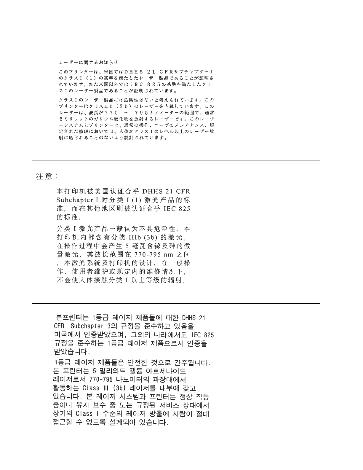
Laser notice
The printer is certified in the U .S. to confo rm to the requir ements of DHHS 21 CFR Subchapter J for Class I (1)
laser product s, and elsewhere is certified as a Class I laser product conforming to the requirements of IEC
60825-1.
Class I laser products are not considered to be hazardous. The pri nter contains internally a Class IIIb (3b) laser
that is nominally a 5 milliwatt gallium arsenide laser operati ng in the wavelength region of 770-795 nanometers.
The laser system and printer are designed so there is never any hum an access to laser radiation above a Class
I level during normal operation, user maintenance, or pr escri bed service condition.
Laser
Der Drucker erfüllt gemäß amtlicher Bestätigu ng der USA die Anforderungen der Bestimmung DHHS
(Department of Health and Human Services) 21 CFR Teil J für Laserprodukte der Klasse I (1) . In anderen
Ländern gilt der Drucker als Laserprodukt der Klasse I, der die Anforderungen der IEC (International
Electrotechnical Commission) 60825-1 gemäß amtlicher Bestäti gung erfüllt.
Laserprodukte der Klasse I gelten als unschädlich. Im Inneren des Druckers befindet sich ein Laser der Klasse
IIIb (3b), bei dem es sich um einen Galliumarsenlaser mit 5 Milliwatt handelt, der Wellen der Länge 770-795
Nanometer ausstrahlt. Das Lasersystem und der Drucker sind so konzipiert, daß im Normalbetrieb, bei der
Wartung durch den Benutzer oder bei ordnungsgemäßer Wartung durch den Kundendienst Laserbestrahlung,
die Klasse I überstei gen würde, Menschen keinesfall s err eicht.
Avis relatif à l’utilisation de laser
Pour les Etats-Unis : cette imprimante est certifiée conforme aux pro vis ions DHHS 21 CFR alinéa J concernant
les produits laser de Classe I (1). Pour les autres pa ys: cette imprimante répond aux normes IEC 60825-1
relatives aux produits laser de Classe I.
Les produits laser de Classe I sont considérés comm e des produits non dangereux. Cett e impri m ante est
équipée d’un l aser de Classe IIIb (3b) (arséniure de gallium d’une puissance nomi nale de 5 milliwatts) émettant
sur des longueurs d’onde comprises entre 770 et 795 nanomètres. L’imprimante et son sys tème laser sont
conçus pour impossible, dans des conditions normales d’uti lisation, d’entr etien par l’utilisateur ou de révision,
l’exposition à des rayonnements laser supérieurs à des ray onnements de Classe I .
Avvertenze sui prodotti laser
Questa stampant e è certificata negli St ati Uniti per ess ere conforme ai requisiti del DHHS 21 CFR Sottocapitolo
J per i prodotti las er di classe 1 ed è certificata negli altri Paesi come prodotto laser di classe 1 conf orme ai
requisiti del la norma CEI 60825-1.
I prodotti laser di class e non sono con sider ati pericol osi. La stampan te conti ene al suo in terno un laser di cl asse
IIIb (3b) all’arseniuro di gallio della potenza di 5mW che opera sulla lunghezza d’onda compr esa tra 770 e 795
nanometri. Il sistema laser e la stampante sono stati progettati in modo tale che le persone a contatto con la
stampante, durante il normale funzionam ento, le operazioni di servizio o quelle di assis tenza tecnica, non
ricevano radiazioni laser superiori al livello della classe 1.
Notices and safety information v
Page 6

4512-420, -430
Avisos sobre el láser
Se certifica que, en los EE.UU., esta impresora cumple los requisitos para los productos láser de Clase I (1)
establecidos en el subcapítulo J de la norma CFR 21 del DHHS (Departamento de Sanidad y Servicios) y, en
los demás países, reúne todas las condiciones expuestas en la norma IEC 60825-1 para productos láser de
Clase I (1).
Los productos láser de Clase I no se consideran pel igrosos. La impre sora contiene en su interior un láser de
Clase IIIb (3b) de arseniur o de galio de func ionamiento nominal a 5 m ilivatios en una longitud de onda de 770 a
795 nanómetros. El sistema láser y la impresora están diseñados de forma que ninguna persona pueda verse
afectada por ningún tipo de radiac ión láser superior al nivel de la Cla se I dur ante su uso normal, el
mantenimiento realizado por el usuario o cualquier otra situaci ón de servic io técnico.
Declaração sobre Laser
A impressora está ce rtific ada nos E. U .A. e m conf ormida de com os requi sito s da reg ulame ntação DHHS 2 1 CFR
Subcapítulo J para a Cla sse I (1) de produt os laser. Em outros locais, está certificada como um prod uto lase r da
Classe I, em conf ormidade com os requisitos da norma IEC 60825-1.
Os produtos lase r da Classe I não sã o conside rados peri gos os. I nternamente , a impr esso ra cont ém um produ to
laser da Classe IIIb (3b), designado laser de arseneto de potássio, de 5 milliwatts ,oper ando numa faixa de
comprimento de onda entre 770 e 795 nanómetros. O sistema e a impressora laser f oram concebidos de forma
a nunca ex ist ir qualquer possiblidade de acesso humano a radiação laser superior a um nível de Classe I
durante a operação normal, a manutenção feita pelo utilizador ou condições de assist ência prescritas .
Laserinformatie
De printer voldoet aan de eisen die gesteld worden aan een laserprodukt van klas se I. V oor de Verenigde
Staten zijn deze eisen vastgeleg d in DHHS 21 CFR Subchapter J, voor ander e landen in IEC 60825-1.
Laserprodukten van klasse I worden nie t als ongevaarli jk aangemerkt. De printer is v oorzien van een laser van
klasse IIIb (3b), dat wil zeggen een gallium ars enide-laser van 5 milliwatt met een gol flengte van 770-795
nanometer . Het laser gedeelt e en de printer zijn z o ont worpen dat bij normaal gebru ik, bij onde rhoud of re parat ie
conform de voorschriften, nooit blootstelling mogelijk is aan laserstraling boven een niveau zoals
voorg e schreve n is voor klasse 1.
Lasermeddelelse
Printeren er godkendt som et Klasse I-laserprodukt, i overenstemmelse med kravene i IEC 60825-1.
Klasse I-laserprodukter betragtes ikke som farlige. Printeren indeholder internt en Klasse IIIB (3b)-laser, der
nominelt er en 5 milliwatt galliumarsenid laser, som arbejder på bølgelængdeområdet 770-795 nanometer.
Lasersystem et og printeren er udformet sål edes, at mennesker aldrig udsættes for en laserstråling over Klasse
I-nive au ved normal drift, brugervedligeholdelse eller ob ligatoriske servicebetingelser.
vi Lexmark™ E350d, E352dn
Page 7

4512-420, -430
Huomautus laserlaitteesta
Tämä kirjoi tin on Yh dysv alloi ssa lu okan I ( 1) lase rlait teide n DHHS 21 CFR Subchapt er J -määrityks en muk ainen
ja muualla luokan I l aserlaitteiden IEC 60825- 1 -määri tyksen mukainen.
Luokan I las e r la itt e id e n e i ka ts o ta ol evan vaarallis ia käyttä jä lle . K irj oi tt im e s sa on si sä i ne n lu oka n IIIb (3 b ) 5
milliwat in galliumarsenidilaser , joka toimii aaltoalueella 770 - 795 nanometriä. Laserj ärjestelmä ja kirjo itin on
suunnitelt u siten, että käyttäj ä ei al tistu luokan I määrityksi ä voimakkaammall e säteilylle kirj oittimen normaalin
toiminnan, käyttäjän tekemien huoltotoimien tai muiden huoltotoimien yhteydessä.
VARO! Av attaessa ja suojalukitus ohitettaessa ol et alttiina näkymätt öm älle lasersäteily ll e. Älä katso
säteeseen.
VARNING! Osynlig laserstrålning när denna del är öppnad och spärren är urkopplad. Betrakta ej stråle n.
Laser-notis
Denna skrivar e är i USA certifier ad att motsvara kraven i DHHS 21 CFR, underparagr af J fö r la serprodukter av
Klass I (1). I andra länder uppfyller skrivaren kraven för laserprodukter av Klass I enligt kraven i IEC 60825-1.
Laserprodukter i Klass I anses ej hälsovådliga. Skrivaren har en inbyggd laser av Klass IIIb (3b) som består av
en laserenhet av gallium-arsenid på 5 milliwatt som arbetar i våglängdsområdet 770-795 nanometer.
Lasersystem et och skrivaren är utformade så att det aldrig finns risk för att någon person utsät ts för
laserstrå lning över Klass I-ni vå vid normal användning, underhåll som utförs av användaren eller annan
föreskriv en serviceåtgärd.
Laser-melding
Skriveren er godkjent i USA etter kravene i DHHS 21 CFR, underkapittel J, for klasse I (1) laserprodukter, og er
i andre land godkjent som et Klasse I-laserprodukt i samsvar med kravene i IEC 60825-1.
Klasse I-l aserprodukter er ikke å betrakte som f arlige. Skriveren inneholder internt en klasse IIIb (3b)-laser, som
består av en gallium-arsenlaser enhet som avgir stråling i bølgel engdeområdet 770-795 nanom eter.
Lasersystem et og skriveren er utformet slik at personer al dri utsettes for laserstråling ut over klasse I-nivå under
vanlig bruk , vedlikehol d som utføres av brukeren, eller foreskre vne serviceoperasjoner.
Avís sobre el Làser
Segons ha estat certificat al s Estats Units , aquesta impressor a complei x els req uisit s de DHHS 21 CFR, apartat
J, pels productes làser de classe I (1), i segons ha estat certificat en altres llocs, és un producte làser de classe
I que compleix els requisits d’IEC 60825-1.
Els productes l àser de classe I no es consideren peril losos. Aquesta impr essora conté un làser de cl asse IIIb
(3b) d’arseniür de gal.li, nominalment de 5 mil.liwats, i funciona a la regió de longitud d’ona de 770-795
nanòmetres. El sistema làser i la impressora han sigut concebuts de manera que mai hi hagi exposició a la
radiació làser per sobre d’un niv ell de classe I durant una oper ació normal, durant les tasques de manteniment
d’usuari ni durant els serveis que satisfacin les condicions prescrites.
Notices and safety information vii
Page 8
4512-420, -430
viii Lexmark™ E350d, E352dn
Page 9

4512-420, -430
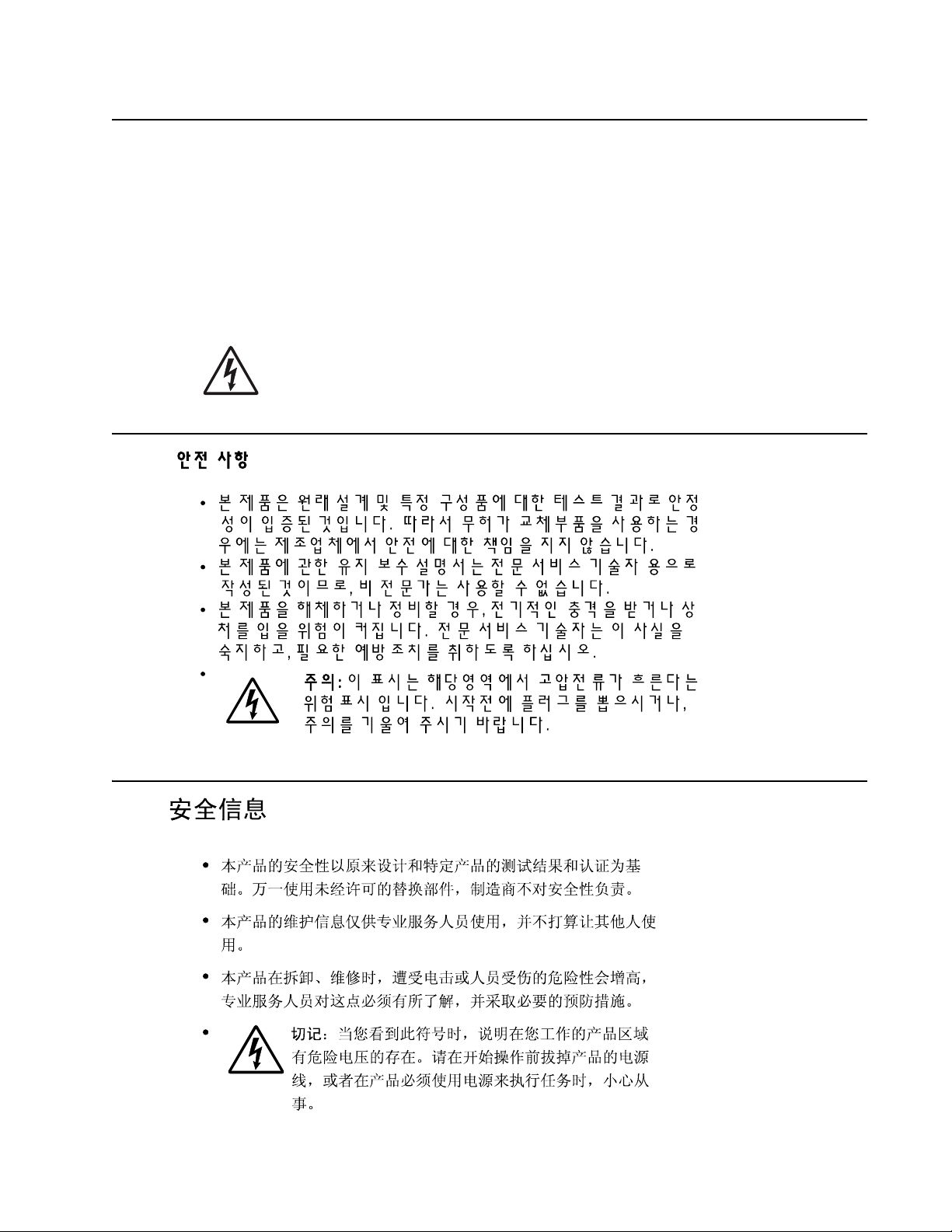
Safety information
• The safety of this product is based on testing and approvals of t he original design and specific
components . The manufacturer is not responsibl e for safety in the event of use of unauthorized
replacement parts .
• The maintenance information for this product has been prepared for use by a professional service person
and is not intended to be used by others.
• There may be an increased risk of electric shoc k and personal injury during disa ssem bly and servicing of
this product . Pro fessional service personnel should understand this and take necessa ry precaut ions.
• CAUTION: When you see th is symbol , ther e is a danger f rom hazard ous v olt age in the area of the
product where y ou ar e working . Unplug the product bef ore you beg in, or use c autio n if t he produc t
must receive power in order to perform the task.
Consignes de sécurité
• La sécurité de ce produit repose sur des tests et des
agréations portant sur sa conception d'origine et sur des composants particuliers. Le fabricant n'assume
aucune respon sabilité concernant la sécurité en cas d'utilisation de pièces de rechange non agréées.
• Les consignes d'entretien et de répar ati on de ce produit s'adressent uniquement à un personnel de
maintenance qualifié.
• Le démontage et l'entretien de ce produit pouvant présenter certains risques électriques, le personnel
d'entretien qualifié devra prendre toutes les précautions nécessaires.
• ATTENTION : Ce symbole indique la présence d'une tension dangereuse dans la partie du
produit sur laquelle vous tra vaillez. Débranchez le produit avant de commencer ou f aites preuve
de vigilance si l' exécution de la t âche exige que le produit reste sous tension.
Norme di sicurezza
• La sicurezza del prodotto si basa sui test e sull'approvazione del progetto originale e dei componenti
specifici. Il produttore non è responsabile per la sicurezza in caso di sostituzion e non autorizzata delle
parti.
• Le informazioni riguardanti la manutenzione di questo prodotto sono indirizzate soltanto al personale di
assistenza autorizzato .
• Durante lo smontaggio e la manutenzione di questo prodotto,
il rischio di subi re scosse elettriche e danni al la persona è più elev ato. Il per sonale di assistenza
autorizzato deve, quindi, adottare le precauzioni necessarie.
• ATTENZIONE: Questo simbolo indica la presenza ditensione pericolosa nell'area del prodotto.
Scollegare il pr odotto prima di iniziare o usare caut ela se il prodotto dev e essere alimentato per
eseguire l'intervento.
Safety information ix
Page 10

4512-420, -430
Sicherheitshinweise
• Die Sicherheit di eses Produkts basiert auf Tests und Zulassungen des ursprünglichen Modells und
bestimmter Baut eil e. Bei Verwendung nicht genehmigter Ersatztei le wi rd vom Hersteller kei ne
Verantwortung oder Haft ung für die Sicherheit übernommen.
• Die Wartungsinformationen für dieses Produkt sind ausschließl ich für die V erwendung durch einen
Wartungsfachmann bestimmt.
• Während des Auseinandernehmens und der Wartung des Geräts besteht ein zusätzliches Risiko eines
elektrischen Schlags und körperlicher Verletzung. Das zus tändige Fachpersonal sollte entsprechende
Vorsichtsmaßn ahm en treffen.
• ACHTUNG: Dieses Symbol weist auf eine gefährliche elektrische Spannung hin, die in diesem
Bereich des Produkts auftreten kann. Zie hen Sie vor den Arbeiten am Gerät den Netzst ecker des
Geräts, bzw. arbeiten Sie mit großer Vorsicht, wenn das Produkt für die Ausfü hrung der Arbeiten
an den Strom angeschlossen sein muß.
Pautas de Seguridad
• La seguridad de este producto se basa en pruebas y aprobaciones del diseño original y componentes
específico s. El fabricante no es responsable de la seguridad en caso de uso de piezas de repuesto no
autorizadas.
• La información sobre el mantenimiento de este producto está dirigida exclusivamente al personal
cualificado de mantenimiento.
• Existe may o r riesg o de descar ga el éctrica y de dañ os person al es duran te e l desmont aj e y la r eparac ión de
la máquina. El personal cualificado debe ser consciente de este peligro y tomar las precauciones
necesarias.
• PRECAUCIÓN: este símbolo indica que el voltaje de la parte del equipo con la que está
trabajando es peligroso. Antes de empezar, desenchufe el equipo o tenga cuidado si, para
trabajar con él, debe conectarlo.
Informações de Segurança
• A segurança deste produto baseia-se em testes e aprovações do modelo ori ginal e de componentes
específico s. O fabricante não é responsável pela segunrança, no caso de uso de peças de subst it uição
não autorizadas.
• As informações de segurança relativas a este produto dest inam-se a profissionais destes serviços e não
dev em ser ut ilizadas por outras pessoas.
• Risco de choques eléct ricos e ferimentos graves durante a desmontagem e manutenç ão deste produto.
Os profissio nais destes serviços devem estar avis ados deste facto e tomar os cuidados necessários .
• CUIDADO: Quando vir este sí m bolo, existe a possível presença de uma potencial tens ão
perigosa na zona do produto em que está a trabalhar. Antes de começar, desligue o produto da
tomada eléctrica ou s eja cui dado so caso o pro duto te nha d e estar liga do à corrent e eléc trica para
realizar a tarefa necessária.
x Lexmark™ E350d, E352dn
Page 11
4512-420, -430
Informació de Seguretat
• La seguretat d' aquest producte es basa en l'avaluació i apr ovació del disseny original i els compo nents
específics.
El fabricant no es fa responsabl e de les qüestions de
seguretat si s'u tilitzen peces de recanvi no autoritzades.
• La informació pel manteniment d’aquest pr oducte està orientada exclusivament a professionals i no està
destinada
a ningú que no ho sigui.
• El risc de xoc elèctric i de danys personals pot augmentar durant el procés de desmunt atge i de servei
d’aquest producte. El personal professional ha d’estar-ne assabentat i prendre
les mesures con venients.
• PRECAUCIÓ: aquest símbol in dica que el voltatge de la part de l'equip amb la qual esteu
treballan t és perillós . Abans de començar, desendoll eu l'equip oextremeu les precaucions si, per
treballar amb l'equip, l'heu de connectar.
Safety information xi
Page 12

4512-420, -430
Preface
This manual contains maintenance procedures for service personnel. It is divided into t he following ch apters:
1. General information contains a general description of the printer and the maintenance approach used to
repair it. Special tools and test equipment are, as well as general environmental and safety instructions.
2. Diagnostic information contains an error indicator table, symptom tables, and service checks used to
isolate failing field replaceable units (FRUs).
3. Diagnostic aids contains tests and checks used to locate or repeat symptoms of printer problems.
4. Repair information provides inst ructions for maki ng printer adjustments and removing and installing
FRUs.
5. Connector locations uses illustr ations to identify the connector locations and test points on the printer.
6. Preventive maintenance contai ns the lubrication specifications and recommendat ions to prevent
problems.
7. Parts catalog contains illus trations and part numbers for individual FR Us.
Appendix A contains service tips and inf ormati on.
Appendix B contains representative print samples.
Definitions
Note: A note provides addition al i nformation.
Warning: A warning identifies something that might damage the product hardware or software.
CAUTION: A caution identifies something that might cause a servicer harm.
CAUTION: When you see this symbol, there is a danger from hazardous voltage in the area of the
product where you are working. Unplug the product before you begin, or use caution if the product
must receive power in order to perform the task.
xii Lexma rk™ E350d, E352dn
Page 13
4512-420, -430
1. General information
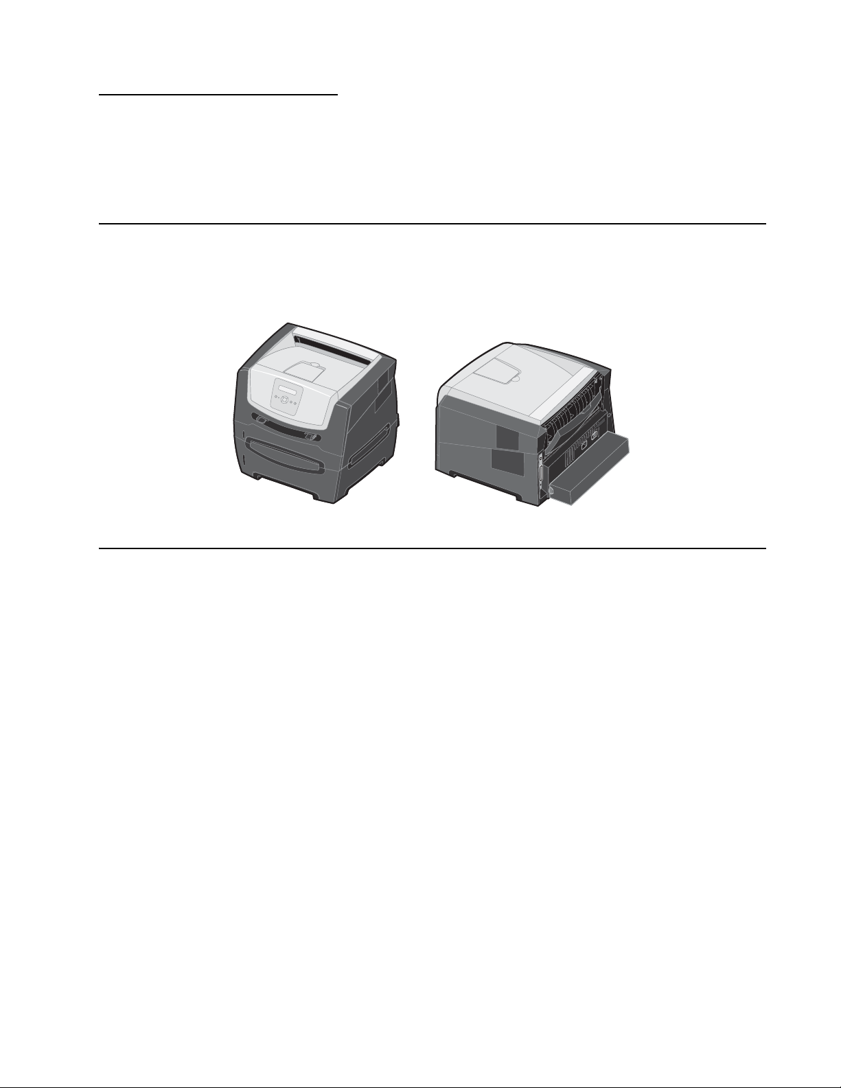
The Lexmark™ E350d and E352dn are monochrome laser printers designed for single users or small
workgroups. This book contains information on E350d and E352dn. For information on E250d and
E250dn, see the 4512-220,-230 service manual.
Model
There are two models: E350d and E352dn. Both models have 32MB memory standard, a parallel USB
connector, INA, ENA option support via USB and/or parallel ports, and prints 35 pages per minute on l ett er-size
media (34 ppm on A4, 29 ppm on legal).
Maintenance approach
The diagnostic information in this manua l le ads to the correct field repla ceable unit (FR U ) or part. Use the error
code charts, symptom ind ex, and service checks to determine the symptom and repair the f ailure. See
“Diagnostics information” on page 2-1 for more inf ormati on. See “Repair information” on page 4-1 to help
identify parts. After completing the repair, perform tests as needed to verify the repair.
General inf ormation 1-1
Page 14
4512-420, -430
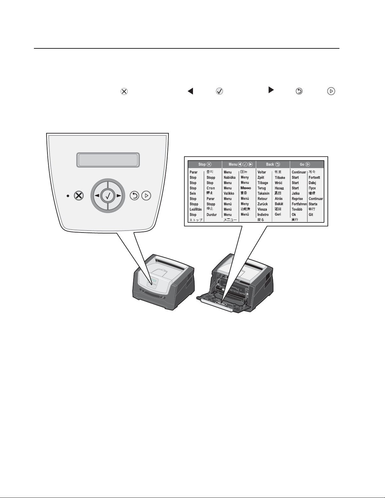
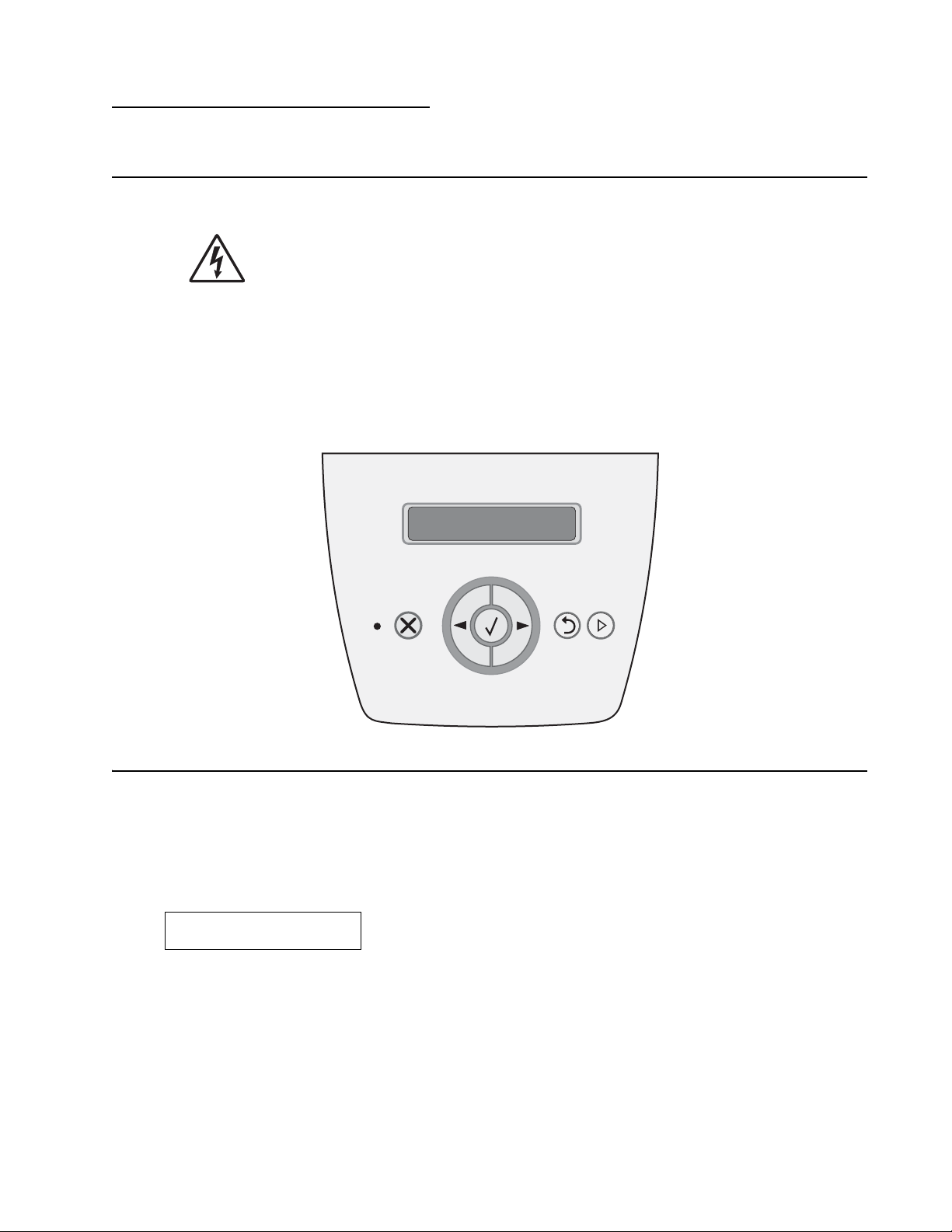
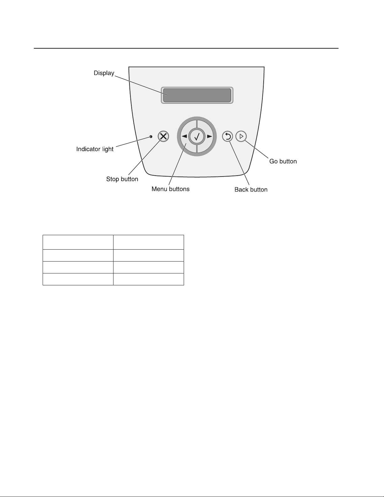
Overview of the operator panel
The operator panel consists of these items:
• A 2-line liquid crystal display (LCD) that shows text
• Six buttons: Stop , Menu (with Left Menu , Select , and Right Menu ), Back , and Go
• An indicator lig ht
A label located on the in side front door shows the operator panel buttons. An additional translated label is
included in the printer box.
1-2 Lexmark™ E350d, E352dn
Page 15

4512-420, -430
Specifications
Memory
Item
Standard DRAM 32MB 32MB
Optional SDRAM 32MB ✔✔
Optional SDRAM 64MB ✔✔
Optional SDRAM 128MB ✔✔
Optional SDRAM 256MB n/a n/a
Maximum DRAM 160MB 160MB
Optional flash memory 32MB ✔✔
Optional f ont cards (DBCS) ✔✔
4512-420
Lexmark E350d
4512-430
Lexmark E352dn
Print spee d
Media Size
Letter—8.5 x 11 in. 35 ppm 35 ppm
A4—210 x 297 mm 34 ppm 34 ppm
4512-420
Lexmark E350d
4512-430
Lexmark E352dn
Legal—8.5 x 14 in. 29ppm 29ppm
Speed measured on media from tray 1, simplex, and at 600 x 600 dpi.
Print qua lit y
Resolution
1200 Image qualit y ¹ ✔✔
2400 Image qualit y ² ✔✔
1200 x 1200 dpi ³ ✔✔
600 x 600 dpi ✔✔
¹ 1200 Image quality defined as 600 dpi with 2 bit IET (image enhancement technology) default mode for all models
² 2400 Image quality defined as 600 and 4 bit IET
³ True 1200 dpi at ½ rated speed.
4512-420
Lexmark E350d
4512-430
Lexmark E352dn
General inf ormation 1-3
Page 16

4512-420, -430
Medi a trays and supply capacity
Item
Available input trays
250-sheet tray ✔✔
550-sheet option drawer ✔✔
550-sheet tray ✔✔
Dust cover ✔✔
Toner and photoconductor
Toner cartridge 1,500 standard pages SWE¹
3,500 standard pages SWE¹
High toner cartridge 9,000 standard pages¹ 9,000 standard pages¹
Photoconductor kit Up to 30,000 ² Up to 30,000 ²
¹ Declared value in accordance with ISO/IEC 1975 2
² Based on approximately 5% coverage, actual yield may vary
4512-420
Lexmark E350d
2,500 standard pages SWE¹
3,500 standard pages SWE¹
4512-430
Lexmark E352dn
1-4 Lexmark™ E350d, E352dn
Page 17

4512-420, -430
Connectivity and compatibility
Item
Data stream emulations
PCL 6 ✔✔
Pos tScri pt 3 ✔✔
HBP ✔✔
PPDS ✔✔
Compatibility Windows/Macintosh/Linux Windows/Macintosh/Linux
Standard local connections
Parallel (IEE 1284 Bi-Di) ✔✔
USB* ✔✔
Standard network connections
Ethernet (10/100 Base TX) n/a ✔
Optional local connections
External print server support ✔✔
Option slots
4512-420
Lexmark E350d
4512-430
Lexmark E352dn
Memory slots (100-pin DIMM) 1 1
Flash memory / option card 2 2
* The E 350d and E352dn products are USB 2.0 certified devices supporting hi-speed (480MB/sec.) data transfer.
General inf ormation 1-5
Page 18

4512-420, -430
Types of print media
Ensure trays are properly loaded. Never mix media types withi n a tray.
Source Sizes Types Weight Input capacity* (sheets)
Input tra y 1
(250-sheet tr ay)
2nd Drawer option
(550-sheet drawer)
Manual feeder A4, A5, A6 (grain
* Capacity for 20 lb print media, unless otherwise noted.
** Use for occasional printing only.
A4, A5, A6 (grain
long only), JIS B5,
letter, legal,
executive, folio,
statement,
Universal¹
A4, A5, JIS B5,
letter, legal,
executive, folio,
statement,
Universal¹
long only), JIS B5,
letter, legal,
executive, folio,
statement,
Universal¹
7 3/4, 9, 10, DL,
C5, B5
Plain paper, bind,
letterhead,
transparencies,
paper labels (single
sided only)
Plain paper, bond,
letterhead,
transparencies,
paper tables (si nglesided only)
Plain paper,
transparencies,
paper labels (singlesided only)
Card stock² • 120–163 g/m²
Envelopes 75 g/m² (20 lb)
60–90 g/m²
(16–24 lb)
60–90 g/m²
(16–24 lb)
60–163 g/m²
(16–43 lb)
(16–43 lb)
Index Bristol
• 75–163 g/m²
(46–100 lb)
Tag
• 250 paper
• 50 labels**
• 50 transparencies
• 550 paper
• 50 tables **
• 50 transparencies
1
¹ Universal size ranges:
– Manual feeder: 76–216 x 127–356 mm (3.0–8.5 x 5.0–14.0 in.) (includes 3 x 5 in. cards)
² Grain short is recommende d. Use rear exit for best results.
1-6 Lexmark™ E350d, E352dn
Page 19
4512-420, -430
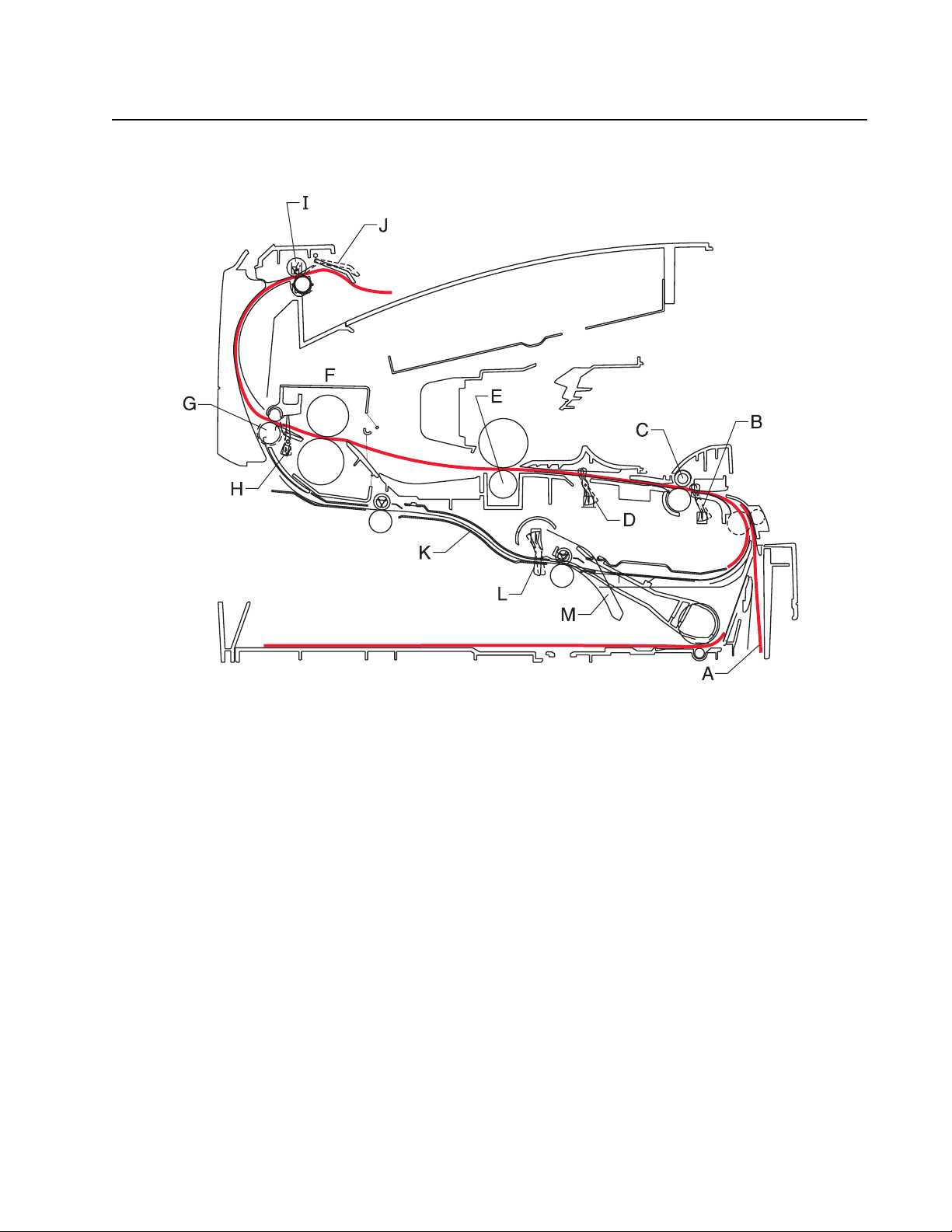
Tips on preventing jams
Paper path
*Measurement s are approximate paper lengths (millimeters)
**Sensors are measured at rotation/position which they are tripped
A Paper path A-B 117.8
B Manual feed sensor B-C 9.6
C Upper end feed rolls C-D 60.5
D Input sensor D-E 49.0
E Transf er roll E-F 110.7
F Fuser F-G 26.9
G Fuser exit rolls G-H 6.2
H Fuser exit sensor H-I 127.2
I Exit rolls I-J 26.4
J Exit sensor I-K 217.4
K Duplex unit K-L 102.5
L Duplex sensor L-M 16.2
M Auto compensator M-B 178.9
General inf ormation 1-7
Page 20

4512-420, -430
Most paper jams can be avoided by correctly loading paper and specialty media in the printer.
The following hints can help prevent paper jams:
• Use only the recommended print media.
• Do not overload the print media sourc es . Make sure the stac k height does not exc eed the maximum hei ght
indicated by the stack line on the labels in the sources.
• Do not load wrinkled, creased, damp, or curled print medi a.
• Flex, fan, and straighten pri nt media before loading it. If jams do occur with the pri nt media, try feeding one
sheet at a time through the manual feeder.
• Do not mix print media sizes, weights, or types in the same print media source.
• Push all trays in firmly after loading the m.
Note: Make sure the media stack is below the maximum media fill indicators on the 250-sheet tray before
pushing the tr ay into the printer.
• Make sure paper guides are positioned before loading the paper or specialty media.
• Do not remove trays while a job is printing.
• Before loading transparencies, fan the stack to prevent sheets from sticking together.
• Do not use envelopes that:
– Have excessive curl
– Are stuck together
– Are damaged in any way
– Contain windows, holes, perforations, cutouts, or embossments
– Have metal clasps, string ties, or metal folding bars
– Have postage stamps attached
– Have any exposed adhesive when the flap is in the seale d position
• Use only recommended media. Refer to the Card Stock & Label Guide available on the Lexmark Web site
at www .l exmark.com for more information about whi ch media provides optimum results for the curr ent
printing environment.
Tools
The remov al and adjustment procedures require the fo ll owing tools and equipment :
• Spring hook
• Needle nose pliers
• Volt-ohmmeter
• #1 and #2 Phillips screwdr ive r
• Slotted screwdriver
1-8 Lexmark™ E350d, E352dn
Page 21

4512-420, -430
Acronyms
ACM Autocompensator Mechanism (or paper feed)
ADC Analog-to-digital Converter
ASIC Application Speci fic Integrated Circuit
CBM Complete Bill Of Material
DEV Development Roll (of print cartridge/photoconductor
DIMM Dual In-Line Memory Module
ENA External Network Adapter
FRU Field Repl ac e a ble Unit
HBP Host Based Printing
HVPS High Voltage Power Supply
LCD Liquid Crystal Diode
LED Light Emitting Diode
LSU Laser Scanning Unit
LVPS Low Voltage Power Supply
NVRAM Nonvolatile Random Access Memory
PC Photoconductor
PCL Printer Control Language
POR Power-On Reset
POST Power-On Self Test
PPDS Per sonal Prin ter Data St ream
PRC People’s Republic of China
TAR Toner Add Roll
SDR Synchronous Dynamic RAM
SWE Shipped With Equipment
USB Universal Serial Bus
V ac Volts alternating current
V dc Volts direct current
system)
General inf ormation 1-9
Page 22

4512-420, -430
1-10 Lexmark™ E350d, E352dn
Page 23
4512-420, -430
2. Diagnostics information
Start
CAUTION: Un plug power from the printer before connecting or disconnecting any cab le,
assembly, or elect roni c card. This is a precaution fo r personal safety and t o prev ent damage to the
printer.
This chapter contains the codes and diagnostic tools to aid in providing corrective action for a malfunctioning
printer . To determine the corrective action to repai r a printer, look for the following information:
• A description of a problem, see “Symptom tables” on page 2-15.
• Information from the operator panel of the printer.
– Models E350d and E352dn ha ve an operator panel with messages. See “Overview of the
operator panel and menus” on page 2-2.
Power–On Self Test (POST) sequence
The foll owing is an example of the events that occur during the POR sequence when the printer is turned on.
1. Diamonds are displayed on the operator panel.
2. While code is being loaded into DRAM, dots scroll across the operator panel.
3. A screen is displayed wi th th e memory and processor speed. A typical example of this message is:
*
32 Mb 366 Mhz
4. Performing Self Test is dis playe d.
5. Busy is displayed.
6. Close Door will be displayed if the cover is open.
7. Any cartridge err ors, such as Defective Cartridge, are displayed.
8. Applicable maintenance messages are displayed.
9. Applicable toner low mess ages are display ed.
10. The printer displays Ready.
Diagnostics information 2-1
Page 24
4512-420, -430
Overview of the operator panel and menus
Indicator light
The indicator light gives information about the status of the printer.
If the light is The printer is
Off Off
On On, but idle
Blinking On and busy
2-2 Lexmark™ E350d, E352dn
Page 25
4512-420, -430
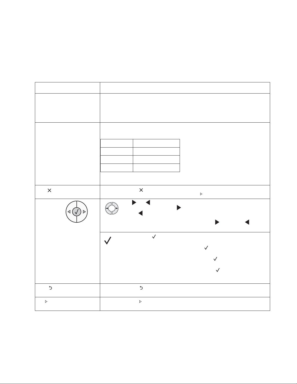
Buttons
Use the six operat or panel buttons to open a men u, scr oll through a list of values, change printe r set tings, and
respond to printe r messages.
Note: Buttons act on the information di splayed on the second line of the operator panel.
The use of the buttons and the layout of the display are desc ribed in the following table:
Button or control panel item Function
Display The display shows messages describing the current state of the printer and indicating
Indicator li ght A green LED is used on the di splay, including the printer status.
Stop Press and release to stop the mechanical operation of the printer. The Not Ready
Menu buttons The and butt ons are used to enter a menu gr oup . Once a m enu gro up
possible printer problems that must be resolved.
The top line of the displ ay is the header line. It will display the current status and the
Supplies (Warnings) status. This is where printer status, supplies messages, and
show -m e screen s are vi ew ed .
If the light is The printer is
Off Off
On On, but idle
Flashing On and busy
message will appear. Operation will resume when is pressed.
is active, press and release to step to the next selection, or press and
release to step to the previous selection.
These buttons can also be used to automatic all y increase or decrease the
desired number of copies.
Press and release to initiate acti on on a selection.
Selects the menu selection displayed on the second lin e o f th e display. If a
menu is displayed such as Paper Menu, then opens t he menu and displays
the first printer setting contained in the men u.
If a menu item such as Paper Source is displayed, then opens the item and
displays the default setting.
If a menu item such as Manual Feeder is displayed, then saves the selection as
the new default setting fo r Paper Source. The printer will display the Saved message
momentarily and then return to the menu item level .
Back Press and release to return to the previous menu group. If at the top of the menu
Go Press and release to place the printer in the Ready state af ter an of f line sit uatio n (to
group , the button functions as a Go button.
exit menus, to clear most messages).
Diagnostics information 2-3
Page 26
4512-420, -430
Diagram of the printer menus
Not all menus or selections will be available on all models or in all situations. These are accessed through the
driver.
Paper Menu
Paper Source
Pape r S i z e
Pape r Type
Custom Types
Universal S etup
Substitute Size
Paper Texture
Pape r Weig h t
Paper Loading
PostScript Menu
Print PS Error
Finishing Menu
Duplex
Dupl ex B i n d
Copies
Blank Pages
Collation
Separator Sheets
Separator Sour ce
Multipage Print
Multipage Order
Multipage View
Multipage Border
PCL Emul Menu
Font Source
Font Name
Pitch
Symbol Set
Orientation
Lines pe r Page
A4 Width
Tray Renumber
Auto CR after LF
Auto LF after CR
Utilities Menu
Quick Demo
Print Menus
Print Stats
Print Net Setup
Print Fonts
Print Demo
Factory Defaults
Hex Trace
Setup Menu
Eco-Mode
Quiet Mode
Print er La ng uage
Power Saver
Resource Save
Print Timeout
Wait Timeout
Auto C o ntinue
Jam Recovery
Page Protec t
Print area
Display Language
Toner Alarm
Job Menu
Reset Printer
Quality Menu
Print Resolution
Toner Darkness
Small Font Enh.
PPDS (if activated)
Orientation
Lines pe r Page
Lines pe r inch
Page Format
Character Se
Best Fit
Tray 1 Renumber
Auto CR after LF
Auto LF after CR
2-4 Lexmark™ E350d, E352dn
Parallel Menu
Std Parallel
Network Menu
Standard Network
USB Menu
Standa r d US B
Page 27

4512-420, -430
Messages and error codes
User attendance messages
The printer control panel displa ys m essages describing the cur rent state of the printer and indicates possible
printer problems that must be resolv ed. This topic provides a list of all printer messages, expla ins what they
mean, and tells how to clear the messages.
The foll owing table lists the messages in alphanumerical order. A message can also be located using the index.
User attendance messages
Message Action
Activa ti ng De mo Mode Wait for the message to clear.
Activa ti ng Me nu Changes Wait for the message to clear.
Activating/Deactivating PPDS Wait for the message to clear.
Busy Wait for the message to clear, or cancel the prin t job.
Cancel li ng Jo b Wait for the message to clear.
Change Cart ri dge Invali d Ref ill The printer has detected an unsupported refilled cartridge. Remove the
Close do or Close the specified door to clear the message.
Deacti va tin g Demo Mode Wait for the message to cl ear.
Defragmenting Flash DO NOT POWER
OFF
Disabling Menus Wait for the message to clear.
Enabling Menus Wait for the message to clear.
Flushing Buffer Wait for the message to clear.
Format ti ng Fl ash DO NOT POWE R
OFF
Invali d Eng in e Code Download valid engine code to the printer.
Invali d Sta nd ard Networ k Cod e The code in an internal pri nt server is not val id. The printer cannot re ceive
indicated print cartridge, and install a new one.
Warning: Do not turn the printer off while this mess age is display ed.
Wait for the message to clear.
Note: The printer settings cannot be changed from the contr ol panel while
the m e nus are disabl ed .
Warning: Do not turn the printer off while this mess age is display ed.
Wait for the message to clear.
and process jobs until valid code is programmed into the internal print
server. Download valid code to the internal print server.
Note: The network code can be downloaded whi le this message is
displayed.
Load manual feeder with <Custom
Type>
Load manual feeder with <Custom
String>
Load manual feeder with <size>
Load manual feeder with <size>
<type>
• Load the specifi ed med ia i n the manual feed tr ay or multipurpose
feeder.
• To ignore the manual feed request and print on media already
installed in one of t he input sources, press .
If the printer fi nds a tray that has media wi th the correct media type
and size, it feeds media from that t ray. If the printer cannot find a
tray with the correct media type and size, it prints on whatever
medi a i s in s t a l led in t h e defaul t i n pu t sour c e.
• Cancel the current job.
Diagnostics information 2-5
Page 28

4512-420, -430
User attendance messages (Continued)
Message Action
Load <src> with <Custom Type
Name>
Load <src> with <Custom String>
Load <src> <size>
Load <src> <type> <size>
Maintenance Replace the maintenance items and, if necessary, reset the printer
Menus Di sab le d The printer menus are disabled. The printer settings cannot be changed
Network A network in ter face is the active communication li nk.
Networ k Car d Bu sy An internal print server (also called an internal network adapter or INA) is
Not Read y The printer i s not ready to rece iv e or process dat a. Someone p res sed to
Parallel A parallel interface is the active com m unication link.
Perfor mi ng Se lf Test The printer is running the series of start-up tests it performs after it is
• Load the input source with the correct type and siz e med ia.
• Cancel the current job.
maintenance cou nter.
from the control panel.
Note: A job can still be canceled.
Contact a system support person.
being reset. Wait for the message to clear.
take the printer offline. Press to make the printer ready to receive jobs.
turned on. Wait for the message to cl ear.
Power Sa ver • Send a job to print.
• Press to warm the printer to normal operating temperature and
display the Ready message.
Printing Directory List The printer is processing or print ing a directory of all files sto red in flash
Printing Font List The printer is processing or printing a list of all available fonts for the
Printing Menu Settings The printer is processing or printing the menu settings page. Wait for the
Printing Device Statistics The printer is printing statist ical information about the printer. Wait for the
Printing Quality Test Pages The print er is formatting and printi ng the Print Quality Test, which consists
Prog Engine Code
DO NOT POWER OFF
Progra m Fla sh
DO NOT POWER OFF
memory. Wait for the message to clear.
specified printer language. Wait for the message to cl ear.
message to clear.
message to clear.
of 4 pages. Page 1 contains a mixtur e of graphics and te xt, pages 2 and 3
contain only gr aphics, and page 4 is a blank page. If Duplex is tu rned on,
then the pages are duplexed; oth erwise they are simplexed. Wait for the
message to clear.
The printer is progr am ming new engine code. Wait for the mess age to
clear and the printer to reset.
Warning: Do not turn the printer off while this mess age is display ed.
The printer is storing resources, such as fonts or macros, in flash memory.
Wait for the message to clear.
Warning: Do not turn the printer off while this mess age is display ed.
2-6 Lexmark™ E350d, E352dn
Page 29

4512-420, -430
User attendance messages (Continued)
Message Action
Prog System Code
DO NOT POWER OFF
Ready Send a job to print.
Remove Paper Standard Bin The standard output bin i s ful l.
Resetting Maint Cnt Valu The printer is resetting the counter that tracks wear on the fuser.
Resett in g PC Cn t Value The printer is resetting the counter that tracks wear on the photoconductor.
Resetting the Printer Wait for the message to clear.
Res Redu ced The printer is reduci ng the resolution of a page in the current jo b from 600
Restoring Factory Defaults Wait for the message to clear.
The printer is progr am ming new system code. W ait for the mess age to
clear and the printer to reset.
Warning: Do not turn the printer off while this mess age is display ed.
dots per inch (dpi) to 300 dpi to prevent a 38 Memory Full error. Res
Reduced remains on the display while the job prints.
Note: When factory def ault settings are rest ored:
• All downloaded resources (fonts, macros, symbol sets) in the
printer memory are deleted.
• All menu settings return to the factory default except:
– The Display Language setting in the Setup Menu
– All settings in the Parallel Menu, Network Menu, and
USB Menu
Std Bin Ful l The standard bin is full.
Toner Lo w • Replace the toner cartridge.
• Press to clear the mes sage and continue printing.
Tray <x> Missing Insert the tray into the printer.
USM The printer is processi ng data through the specified USB port.
Waiting The printer has received a page of data to print , but is wai ting f or an End of
Job command, a Form Feed command, or additional data.
• Press to print the contents of the buffer.
• Cancel the current job.
Diagnostics information 2-7
Page 30

4512-420, -430
Cartridge error messages
Error Description
31 Defec tiv e ca rtridge
32 Unsup por te d print cart rid ge
33 Inval id re fi ll
Paper jam error codes (200-series)
Note: The Event log (See “Event log” on page 3-21) will list any of these er rors that have occ urred.
Repeating jams or jam messages can be caused by any of the following:
• Fau lty/contaminated pick solenoids or worn cams of the solenoids.
• Faulty/contaminated flags or springs.
• Debris in the paper path.
• Media not of the specifi ed length.
Paper jam error codes (200-series)
Error Description
200.00 Paper jam around input sensor.
200.01 Classic input jam. The media is too long ov er the input sensor. Possible causes include multi-sheet feed, tray
200.02 The main input sensor never became uncovere d fro m the sheet ahead.
200.03 The video never started on the page at the input sensor within two inches after hitting the input sensor
200.04 The media at the input sensor before interrupt occurred - not enough time elapsed since the printhead started
200.06 Imaged page not expected page (bounc y passthru sensor)
200.08 Media reached the input sensor before the EP was ready
200.09 Transfer servo never started
200.12 Media detected at manual feeder sensor when not expected. Possible causes include user insert of media
200.13 The input sensor is covered when th e media is not expected (media in machine during warm-up)
200.14 Trailing edge cleared m anual feed, but did not success ful ly debounce the sensor. Potential causes are a small
200.15 UNRECOVERABLE NO GAP JA M. Engine detected no gap at the manual feeder sensor, attempted to open
size sensing problem, and media slippage.
to expect the printhead mirror motor loc k. Possible causes include bouncy sensor or exceptionally fast pick perhaps due to media pre-s taged in the source tray.
when motor is running or pre-staged media in the tray.
gap or a bouncy manual feed sensor.
the gap by stopping the feed rolls, but no trailing edge was ever seen at th e input sensor.
200.16 Transport motor error detected
200.17 Took too long to ramp up transport motor
200.18 Manual feeder sensor never became uncovered from the sheet ahead.
200.19 The media never reached the input sensor, but was detected at manual feeder sensor.
2-8 Lexmark™ E350d, E352dn
Page 31

4512-420, -430
Paper jam error codes (200-series) (Continued)
Error Description
200.20 The media is too long over the manual feeder sensor. Possible causes include multi-shee t f eed, media size
200.22 FAILED SMALL GAP OR NO GAP JAM RECOVERY. Engine detected small gap or no gap at the manua l
200.23 Laser Servo never started due to potential conflict with the tr ansfer servo. Possible cause s: sl ow or missing
200.24 The measured gap at the input sensor is too small to meet the video delivery requirements. (There i s not
200.26 The trail ing edge never cleared the input sensor when f eeding out the media that was detected during warm-
200.27 Printhead Driver: Mirror motor fel l out of lock condit ion after the media at t he input sensor - more time el apsed
200.28 First writing line of a page at the dev eloper nip, b ut laser servo cleanup is not co mplete. Likely pre staged
200.29 Printhead drive control out of range due to an external event beyond what the control is designed to handle.
200.30 Narro w media sensor covered during warm-up.
200.32 Media more than 14 inches too long over the manual feeder sensor. Possible causes include multi-sheet feed
(length) problem, pre-staged media in the tray.
feeder senso r , opene d the gap b y s toppi ng the feed rolls, but nev er sa w the l eading ed ge of th e seco nd pag e at
the input sensor.
transport motor positi onal feedback, or the media is transf erred too quick ly t o the input sensor.
enough time since prior image finished to start new image)
up.
since the printhead than the expected stab le lock time, but less than the printhead jitter-stab le specification.
Mirror motor fell out of lock condit ion after media at the input se nsor - more time elapsed since the printhead
than expected stable lock time, but less than the pri nthead jitter-stab le specification.
media or a fast paper feed.
Probable causes: ESD or noise on hsync signal.
or pre-staged media in the tray.
200.33 Page from tray 1 did not reach the input sensor after multiple attempts. Page did make it out of the t ray at least
200.34 Timed out waiting for page from tr ay 1 to reach the input sensor after multiple pick attempts, but the page was
200.35 Failed to create hsync during auto alignment
200.36 Lost hsyncs during auto alignment
200.37 Timeout on data collection during auto align me nt
200.38 Interpage servo gap is sma ll er than expected f or printhead offset target evaluat ion
201.00 Paper jam between input and exit sensor
201.01 Transport motor identificati on failed to identify either motor after two tries.
201.02 Exit sensor never made by leading edge of page. Also known as internal jam.
201.03 Video never started on the page at the input sensor within two inches after hitting the input sensor
201.05 Restart attempted after an internal jam without the cover open/close event. It is likely that the jam was never
201.25 Exit sensor never made by leading edge of media when feeding out the media th at was detected during wa rm-
201.26 Page at fuser nip before fuser started ramping tow ard desired temperatu re. Indicates code may be receiving
as far as the manual feeder sensor. Possible cause is that the page stalled at the alignment gate.
later detected at the input sen sor while w ait ing for any page(s ) ahead to clear t he pap er path. P ossi b le caus e is
that the page is delayed at the alignment gate.
cleared.
up.
more hall interrupts than intended
Diagnostics information 2-9
Page 32

4512-420, -430
Paper jam error codes (200-series) (Continued)
Error Description
201.27 Page at fuser nip before fuser reached acceptable operating temperature. Page arrived at fuser earli er than
202.00 Paper jam around exit sensor.
202.01 Exit sensor never broke on the trailing edge of the sheet at the exit sensor.
202.02 Exit sensor never broke from sheet ahead of page heading toward the exi t sensor.
202.06 Exit sensor bounced
202.13 Exit sensor covered, media not expected (media not i n mac hine during warm-up)
202.25 Exit sensor ne v er bro k e from the sheet ahead of th e page heading to w ard the e xit sens or when f eeding out the
202.26 Trailing edge never cleared e xit sensor when feeding out media that was detected duri ng warm-up.
202.32 Long media or shingled multi f eed stopped before sendi ng to duplex.
231.00 Duple x jam while reve rsi ng into the device
231.01 Duple x sensor never made by leading edge reversing into the duplex.
231.02 Bouncy dupl ex sensor never made.
232.00 Duple x jam while staging in the de vice
232.01 Duple x sensor never broke by the sheet ahea d after reversing into the duplex.
232.02 Page in duplex ahead of current reversing page never staged.
expected, so it was probably staged
media detected during warm-up.
233.00 Duple x jam while picking from the device
233.01 Page in duplex never pick ed.
233.02 Feed error picking from the duplex.
233.03 Paper never reached the input sensor, but was dete cted at the manual fee d sensor.
234.01 Duple x sensor covered duri ng warm-up.
235.01 Inv alid duplex medi a
241.00 Paper jam near tray 1.
241.10 Second pic k attempt failed fr om Tray 1
241.12 Second pic k from manual feeder, tray 1, or feeder f ailed when the media was in the source while other sheets
241.16 Failed to feed fro m tray 1. Pages in the paper path hav e been fl ushed to the output bin.
241.17 MISIDENTIFIED SMALL GAP JA M. Engine detected small gap at the man ual feeder sensor, attempted to
241.18 MISIDENTIFIED NO GAP JAM. Engine detected no gap at the manual feeder sensor, attempted to open the
241.19 Second pic k attempted fai led from Tray 1, no pages printed since calli ng a 241.10 or a prior 241.19.
were committed to the paper path.
open the gap by stopping the feed rol ls, traili ng edge was seen at the input sensor, m anual feeder sensor is no
longer covered.
gap by stopping the feed rolls, t railing edge was seen at the input sensor , manual feeder sensor is no longer
covered.
242.00 Paper jam near tray 2.
2-10 Lexmark™ E350d, E352dn
Page 33

4512-420, -430
Paper jam error codes (200-series) (Continued)
Error Description
242.01 Took too long to ramp up dc feed motor
242.08 Receiv ed lots of dc feed interrupts before losi ng them
242.10 Second pic k attempt failed fr om Tray 2
242.12 Second pic k from manual feeder, tray 1, or feeder f ailed when media was in the source, other sheets were
242.16 Failed to feed fro m tray 2. Pages in the paper path hav e been fl ushed to the output bin.
251.00 Paper jam near the manual feeder.
251.10 Second pic k attempt failed fr om manual feeder.
251.11 Failed to feed fro m manual feeder. Pages in the paper path have been f lushed to the output bin.
251.12 Second pic k from manual feeder, tray 1, or feeder f ailed when media was in the source while the other sheets
251.19 Media never reached the input sensor from the manual feeder.
committed to the paper path.
were committed to the paper path.
Diagnostics information 2-11
Page 34

4512-420, -430
Service error codes
Service error codes are gener ally non-recoverable except in an intermittent condi tion when the printer can be
put into POR to temporarily recover fro m the error condition.
Service error codes (9xx)
Error Description
Engine software service errors
902.xx Engine software error
Transfer service errors
917.00 Transfer service error
917.01 Transfer servo result too low.
Fuser service errors
920.00 Under temperature during steady state control.
920.01 Fuser took too long to heat up after transitioning to new enhanced mode.
920.02 Fuser fell too far below des ir ed temperature while printing.
920.03 Fuser too cool whi le checking for slope change.
920.04 Fuser too cool when heating to desired temperatur e after slope change.
920.05 Fuser under temperature while printing
920.06 Fuser under temperature while printing
920.07 Fuser under temperature while printing
920.08 Fuser temperature did not increase after IR recovery.
920.20 Belt fuser unde r temperature during steady st ate control. This can occur in prin ti ng or standby modes .
921.00 Under temperature during standby control.
921.01 Fuser temperature did not reach standb y temperature after two attempts
922.00 Fuser failed to ramp to target temperature
922.01 Fuser did not reac h standby temperature in time (standby control)
922.07 Media reached fuser nip and fuser is under temperature
922.08 Fuser warm-up failure (motor start conditi on)
922.09 Fuser warm-up failure (compres sion set)
922.20 Belt fuser failed to reach the preheat temperature for the motor to start during warm-up.
922.21 Belt fuser was under temperature when the media reached the fuser nip.
923.00 Fuser is over temperature.
923.01 Fuser is over temperature. This applies to the fuser and belt fusers.
924.00 Open thermistor check.
924.01 Open thermistor chec k failure . This applies to the fuser and belt fusers.
2-12 Lexmark™ E350d, E352dn
Page 35

4512-420, -430
Service error codes (9xx) (Continued)
Error Description
924.02 Open thermistor check failure. The ADC failed to converge. Possible noisy thermistor signal. This applies to the
Fan service errors
927.00 Service fan error
927.03 Main fan took too long to ramp up
927.04 Main fan is under speed or stalled during sp eed adjustment state
927.05 Main fan overspeed during speed adjustment state.
927.06 Main fan capture data is invalid and speed control is at maximum in fan control idle state
927.07 Main fan capture data is invalid and speed control is at maximum in fan control adjustment state.
Printhead service errors
931.00 No first hsync
931.01 No first hsync
932.00 Lost hsyncs
932.01 Lost hsyncs
933.00 Printhead boost signal fai lure
935.10 Printhead s w eep error, s wept through Hz range wi thout finding the resonant fr equency
fuser and belt fusers.
935.11 Printhead s w eep error, autosweep hw state
935.12 Printhead s w eep error, coa rse sweep state
935.13 Printhead s w eep error, init fine sweep state
935.14 Printhead s w eep error, fine sweep state
935.15 Printhead s w eep error, che ck prelim amp state
935.16 Printhead s w eep error, ena ble amp Kp state
935.17 Printhead s w eep error, amp Kp f ailed to conv erge
935.18 Printhead s w eep error, ena ble amp Ki state
935.19 Printhead s w eep error, amp Ki failed to conv erge
935.20 Printhead s w eep error, ena ble offset control ler state
935.21 Printhead sweep error , load scan regs state
935.22 Printhead sweep error, fwd and rev capture times differ by too much
935.23 Printhead sweep error, check sweep accuracy state
935.24 Printhead s w eep error, reserved
935.25 Printhead sweep error , detected resonant frequency out of expected range
935.26 Printhead s w eep error, timed out waiting for end of sweep
Transport motor service errors
Diagnostics information 2-13
Page 36

4512-420, -430
Service error codes (9xx) (Continued)
Error Description
936.01 No lock detected at normal motor start
936.02 No lock detected at motor start for motor ID
936.03 No halls detected at motor start
936.04 Fa il ed to stop within timeout
936.05 Stall detected during speed control
937.00 Main transport motor lost lock
937.01 Main transport motor lost lock, detected by engine control
937.02 Overspeed detected during posit ion control
937.03 Oversp eed detected during speed control
Power supply service errors
940.00 LVPS service error
940.01 Line frequency outside allowed range of 45Hz-64Hz
940.02 Line frequency below 43Hz
940.03 No zero cross detected on belt fuser model
2-14 Lexmark™ E350d, E352dn
Page 37

4512-420, -430
Symptom tables
POST symptom table
Symptom Action
The main motor, cooling fan, and fuser do no t come
on.
POST completes, but the LCD does not come on. See “Operator panel service check” on page 2-21.
Main motor does not come on. See “Main motor service check” on page 2-20.
Fan does not come on. See “Cooling fan service check” on page 2-18.
Fuser does not cycle. See “Fuser service check” on page 2-19.
Fuser does not turn on and off. See “Fuser service check” on page 2-19.
The paper feed picks and tries to feed media. See “Paper feed service checks” on page 2-21.
Note: Investigate any displayed codes before proceeding with these sym ptoms. For example, a missing toner cartridge will
prevent PO S T from completing.
See “Cover interlock switch service check” on page 2-18.
Diagnostics information 2-15
Page 38

4512-420, -430
Printer symptom table
Symptom Action
Fan noisy or fan not working. See “Cooling fan service check” on page 2-18.
Fuser parts melted. See “LVPS/HVPS service check” on page 2-20.
Toner not fused to the media. See“Fuser service check” on page 2-19 or “Solving print
Paper jams. See “Paper feed service checks” on page 2-21.
Main motor noisy or not moving. See “Main motor service check” on page 2-20.
Media ske w. See “Paper feed service checks” on page 2-21.
Printer not communicating with host. See “Parallel or USB port service check” on page 2-23.
Front access cover wil l not close. See “Cover interlock switch service check” on page 2-18.
Operator panel button not responding. See “Operator panel service check” on page 2-21.
Operator panel lights are off or very dim. See “Operator panel service check” on page 2-21.
Blank page. See “Blank page” on page 2-24.
Black page. See “Black page” on page 2-25.
Heavy background. See “Heavy background” on page 2-25.
Light print. See “Light print” on page 2-27.
White or black lines or bands. See “White or black lines or bands” on page 2-27.
Toner on back of page. See “Toner on back of page” on page 2-27.
Media never picks. See “Media never picks” on page 2-22.
quality problems” on page 3-28.
Media feeds continuously. See “Media picks during POST and/or continuously” on
Media wrinkled or bent. See “Media “trees,” wrinkles, stacks poorly, or curls” on
Dead machine (no power). See “Dead machine service check” on page 2-19.
Print quality problems
• Light print
• Blurred characters
• Toner on both sides of media
• Toner not fused
• Streaks
• Blank pages
page 2-21.
page 2-23.
See “Solving print quality problems” on page 3-28.
2-16 Lexmark™ E350d, E352dn
Page 39

4512-420, -430
Service checks
Service checks which involve measuring voltages on the LVPS/HVPS (low voltage power supply/
high voltage power supply board) should be performed with the pri nter positioned on its back side.
Note: When making voltage readings, always use frame ground unless another ground is
specified. See the wiring diagram in the back of the book for more information.
Controller card service check
Controller card service check
FRU Action
Controller card
assembly
Warning: Do not
replace the operator
panel and control ler
card at the same time.
Each card contains t he
printer settings . When
either of these cards is
new , it obtai ns som e of
the settings from the
other card. Settings
are lost when both are
new and replaced at
the same time.
POST (Power-On Self Test)
Note: The printer should complete PO ST in appr oximately 30 seconds.
If the printer fails to display lights or activa te the drive motor, fuser or fan, check the
following order:
1.Power to the LVPS/HVPS
2.Power from the LVPS/HVPS to the controller card
3.Cables are plugged in correctly, especially for the operator panel. The printer will not
power-up wit hout a functioning operat or panel.
4.The controller card assembly.
5.The operator panel. See “Operator panel service check” on page 3-21.
Verify +24 V dc input from the LVPS/HVPS.
1.T urn the printer off.
2.Disconnect the LVPS/HVPS cable from the controller card at J19.
3.T urn the printer on.
4.Verify +24 V dc on positions 8 and 9 of the cable connector.
5.If voltage is co rr ect, c heck t he co ntin uity i n the ot her cond uct ors of t he cab le . If the cab l e
is good, check the connectors to the controller board.
6.Verify that pins 7 and 12 on both the cable and the card connector are grounded.
7.If grounds ar e not correct on the cable, but the cable posses continuity otherwise, check
the LVPS/HVPS.
8.If the grounds are not corre ct on the controller card, replace the controller card. (Check
with one probe on the connector pin and the other on the card’s ground plane f ound at
each screw head.)
Controller card voltage outputs
Turn the printer off, and plug the LVPS/HVPS cable into J19 of the controller card. See the
wiring diagram at the end of the book which identifies the voltages and groun ds for a good
controller card.
Turn the printer off bef ore plugging or unplugging any connectors .
Diagnostics information 2-17
Page 40

4512-420, -430
Controller card service check (Continued)
FRU Action
LVPS/HVPS Verify main power to controller card
With the printer off, unplug the LPS/HVPS cable at J19 on the controller card. Verify
grounds on pins 7, 12, and 14 for both the cable and the controller card. I f any of these
grounds are incor rect, check the cab le for continuity. Replace the cable or the respectiv e
card as necessary.
Turn the printer on with the cable still unplugged, and verify the following on the cable
(controller card wil l not be powered):
Pins Voltage
J19-8 +24 V dc
J19-9 +24 V dc
J19-13 +5 V dc
If any of the voltages are incorrect, replace the LVPS/HVPS. See “Dead machine service
check” on page 2-19.
Cooling fan service check
FRU Action
Cooling fan Make sure the fan cable plug is properl y seated at J4 (controller card).
Turn the printer off, and disconnect the cooling fan cabl e fr om the controller card.
Turn the printer on. Within a few seconds, the controller card assembly should apply
+24 V dc to pin 2.
• If voltag e is pr esent and the fan is not turning , re place the cooling fan. If the fan stil l
doesn’t funct ion, replace the control ler card.
• If voltag e is not present, check the con tr oller card.
Cover interlock switch service check
Note: Make sure a print cartridge assembly is installed and the cover closes all the way, engaging th e cover
open swi tch lever.
FRU Action
Cover interlock switch Disconnect the cover interlock cable from the controller card at J6.
With the printer turned off, verify continuity between cabl e pin 1 and pin 2 with the door
closed and discontinuity with the door open.
V erify contin uity betw een cab le pi n 1 and pin 3 wit h the door open and disc ont inui ty with the
door closed.
Verify discontinuity between cable pins 2 and 3 whether the door is open or closed.
• If either fails, replace the cover interlock switch.
• If both pass continuity, turn the printer on, and measure +5 V dc on pin 2 at J6 on the
controller card.
• Verify pin 3 at J6 is ground.
• If vol tage or ground is not prese nt, see “Controller card service check” on page 2-17
for mo re info rmation.
2-18 Lexmark™ E350d, E352dn
Page 41

4512-420, -430
Dead machine service check
CAUTION: Check the AC line voltage. The voltage should be within the following limits:
• 100 V ac (volts alternating current) – 127 Vac for the 110 V printer
• 200 V ac – 240 V ac for the 220 V printer
FRU Action
Unplug the printer. Remove the LVPS/HVPS, and check the fuses for continuity.
• If open, replace the LVPS/HVPS.
• If not open, chec k the switch conti nuity across its con ductors with the switch on. Turn
the switch off. Plug the AC line into the LVPS/HVPS and switch unit on.
LVPS/HVPS
Note: Voltages may be exposed at several places on the board. Do these verifications , and
then unplug the card:
• Verify 24 V dc on pins 8, 9, and 10 at PCN1.
• Verify approxi mately 3V on pins 1–3.
• Verify approximately 5V on pins 4 and 13.
• If voltages are not correct, replace the LVPS/HVPS.
• If voltag es are correct, chec k the controller card. See “Controller card
service check” on page 2-17.
Fuser service check
When toner is partially fused to the media, it is usually caused by l ow fuser temperatur e.
The line vol tage to the printer must be within the following limits:
• 100 V ac–127 V ac for the 110 V model printer
• 200 V ac–240 V ac for the 220 V model printer
This printer uses a belt fuser and therefore does not have a lamp.
Fuser service check
FRU Action
Unplug the printer, and disconnect the f user cable plug from the LVPS/HVPS board
connector at PCN5.
Check for continuity across the fuser by checking across the connector pins.
Fuser power cable
LVPS/HVPS
Fuser
Make sure the fuser thermistor is correctly connected to the controller board at J13. If the
problem persists, disconnect the thermistor cable and check for less than +5 V dc on pin 1.
Pin 2 should be ground. If line voltage is incorrect on pin 1, see “Controller card service
check” on page 2-17 for more info r m a tion.
• If there is continui ty, check the LVPS/HVPS. See “LVPS/HVPS service check” on
page 3-20.
• If there is no contin uity, disconnect the fuser power cable at both ends and check each
conductor for continuity. Replace cable if necessary.
• If the cable te sts good, replace the fuser.
Fuser
Disconnect the th ermist or cable from J13 on the controller card.
Measure the resist ance across the ends of the thermis tor cable.
Replace the fuser assem bly if the resistance is lower than 1K ohm or shorted.
Note: Resistance measures approximately 400K ohms when cool and 1K ohms hot.
Diagnostics information 2-19
Page 42

4512-420, -430
LVPS/HVPS service check
FRU Action
LVPS portion of board
Fuses that open typically indicate a fa ulty LVPS/HVPS.
Disconnect the po wer cable, and open th e LVPS/HVPS enough to test the swi tch. The
switch will show continuity across the conductors with a meter when the switch is on. If the
LVPS/HVPS
switch is good, see “Dead machine service check” on page 2-19 for more diagnostics.
HVPS portion of board
Problems with the HVPS are exhibited in the print quality. See “Print quality service
checks” on page 2-24 for more information.
Main motor service check
FRU Action
Turn off the printer, and unplug the main motor cable at J17. Turn on the printer, and chec k
for the following voltages at J17:
J17 pins Voltages
Main gear drive
Main motor cable
LVPS/HVPS
Controller card
Warning: Do not
replace the operator
panel and control ler
card at the same time.
Each card contains t he
printer settings . When
either of these cards is
new, it obtains the
settings from the other
card. Settings are lost
when both are new
and replaced at the
same time.
Verify ground at pin 5 for both the card and cable.
• If these voltages are correct, check the main motor cable for continuity.
- Remove the lef t side cover to access the connector on the motor.
- If continuity exists on each wire, replace the main gear drive which includes the
motor.
- If continuity does not exist on one or more of the wires, replace the motor cable.
• If these voltages are not correct, see “Controller card connector pin values” on
page 5-2, or replace the cont roller card. See “Controller card removal” on page 4-13.
Pins 1–4 Approx. +3.3 V dc
Pin 6 Approx . +5V dc
Pins 7–9 10 V dc–24 V dc
2-20 Lexmark™ E350d, E352dn
Page 43

4512-420, -430
Operator panel service check
Inspect the operator panel cabl e for damage. Mak e sure the cable is plugged in securely. Run POST and check
each light for proper operation. See “Power–On Self Test (POST) sequence” on page 2-1.
LCD Operator panel service check
FRU Action
Operator panel (LCD)
Controller card
Warning: Do not
replace the operator
panel and control ler
card at the same time.
Each card contains t he
printer settings . When
either of these cards is
new, it obtains the
settings from the other
card. Settings are lost
when both are new
and replaced at the
same time.
Lights
If the LCD does not come on, open the contr oller card cage and locate th e operator panel
connector at J3. Make sure the cable is properly connected to the controller card and the
controller card has input voltage to it.
With the printer on, v eri fy t he following without disconnecting th e cable:
• Pins 1, 3, 5, and 6—3.3 v
•Pin 2—5 v
• Pins 4 and 7—GND
If these are correct and the operator panel is not functioning, replace the operator panel.
If any are incor rect, see “Controller card service check” on page 3-17.
Buttons
If the buttons do not respond, replace the operator panel. There is no tes t or repair for the
faulty switches.
Paper feed service checks
Paper jam error indication during POST
FRU Action
Fuser (exit sensor) If the exit sensor flag, which i s visible at the back of the fuser, is i n any position other than
vertical, the printe r will display a paper jam . Make sure the flag is operating freely. Replace
the fuser if the sensor is damaged.
Input/dupl ex sensor
Manual feed sensor
Make sure the input paper feed sensor s are working properly. A stuck or incorrectly installed
sensor causes a paper jam indication.
Media picks during POST and/or continuously
FRU Action
ACM
Manual feed clutch
Check the ACM clutch for wear. The solenoid interacts with the clutch to control the motion
of the pick tires.
If the ratchet teeth of the ACM clutch assem bly are worn or broken, the sol enoid may not
stop the ACM from rotating. Replace the ACM clutch assembly if necessary.
Check the manua l feed clutch for damage.
Diagnostics information 2-21
Page 44

4512-420, -430
Media picks but stops halfway through the printer
FRU Action
Input/duplex sensors
(under print ca rtridge assembly)
Input sensor (manual)
Make sure the input sensors are working properly.
Check for a broken or stuc k flag on the input sensors.
Make sure t he cables are seated on the cont roller card at J23 (Tray 1 input) and
J20 (manual input).
Check for about +5 V dc on pin 6 at J23 (Input/duplex sensor) and pin 3 at J20
(Input sensor).
• If correct , replace the input paper f eed sensor .
• If these voltages are not correct, replace the controller card.
Media never picks
FRU Action
Paper feed (pick tires) tray 1
Paper feed (pick tires) tray 2
Media drive ASM
Media feed clutch ASM
Manual feed clutch ASM
P/U and manual feed solenoid
ACM dr ive shaft
Open the left cover, and verify that the solenoids and clutches are functioning
when an attempt is made to feed the media.
Make sure the rubber tires on the ACM are installed and clean.
Replace the tires, ACM drive, clutch assemblies, solenoids, or drive shaft as
necessary.
Media occasionally mispicks or picks multiple sheets at once
FRU Action
Tray 1
Tray 2 (option)
Paper pick tires
(Tray 1 or tray 2)
ACM clutch complete bil l
of material (CBM)
Manual feed clutch CBM
Media feed clutch ASM
(tray 1 only)
Manual feed clutch ASM
Controller card
P/U and manual feed
solenoid ASM.
Check tray for media catch points.
If the sheet being fed stops momentarily, the ACM applies addi tional vertical force,
causing additional sheets to fee d.
Do not mix media types in one tray.
Check the tires in t he ACM assembly for signs of wear or damage.
Replace the tires as necessary.
Open left co v er , and observ e t he solen oi d and clut ch act ions at th e A CM and man ual feed
shafts as a print job is attempted.
Replace the f aulty part.
Disconnect the sol enoid cable at J21 on the con tr oller card.
Measure the resistance across cable pins 1 and 2 and then pins 3 and 4.
• The resistance should be
180–250 ohms.
• If it is not, replace the solenoid assembl y.
• If the resistance is 180–250 ohms, check the controller card. See “Controller card
service check” on page 2-17 for more information.
Replace controller card as necessary.
2-22 Lexmark™ E350d, E352dn
Page 45

4512-420, -430
Media skews
FRU Action
Paper feed (pick tires) tray 1
Paper feed (pick tires) tray 2
Tray 1
Tray 2 (option)
Check tires for debris. If tires are new, try reversing each on its hub.
Check side g uid es on Tray 1 and Tray 2. Guides set fo r a ful l stac k of m edia ma y be
too wide when the stack is short.
Media “trees,” wrinkles, stacks poorly, or curls
FRU Action
Fuser This probl em is most likely due t o a worn back up roll. I t causes the pri nter to run hot ter than
required for the media being printed. Excessive heat can cause media treeing problems,
poor stacking, or curl.
Print the menu sheet found under Utilities.
Look at the medi a set ting s. Some , s uch as car d s tock or roug h te xt ure , ma y r equir e a highe r
fuser temperature, which leads to more of these problems (except stacking) in plain paper.
• Change settings using the printer driver.
• Use the local printer set up utility (included on th e CD) to chan ge the NVRAM
settings.
Try a different ream of paper . Moist media has a higher tendency to crease (treeing) and
curl.
Parallel or USB port service check
1. Perform a print test to make sure the printer prints correc tl y. Veri fy that the indicator light is on, then print
the menu settin gs by selecting Print Menu under Utilities.
2. Be sure the printer parallel cable is designed for bidirectional printing.
3. Be sure the user’s application is set up correctl y.
4. If the internal print test page prints correctl y, the user’s applicati on/printer driver is set up correctly, and the
correct bidirectional parallel cable is installed, but the printer still fails to print on command from the host
computer, replace the cont roller card.
5. Check the USB cable for continuity.
Diagnostics information 2-23
Page 46

4512-420, -430
Print quality servic e chec k s
Note: Ensure the cover closes tightly. A gap in the opening may allow light to expose the photoconductor
resulting in a ‘dirty’ print. Extreme environmental conditions, temperatures, and humidity will affect the print
quality.
Using print quality test pages
To help isolate print quality problems, like st reaking, print test pages using the print quality test pages . To print
the print quality test pages:
1. Enter Configuration Menu.
a. Turn off the printer.
b. Turn on the printer while pressing and holding and .
c. Release the buttons when Performing Self Test displays.
d. The message CONFIG MENU displays.
e. Press to Prt Qual ity Pgs.
f. Press to print the pages .
Four pages print to help evaluate print quality. The first page has various fonts and a graphic, the
second page is gray with graphics, the third page is black, and the last page is b lank.
2. Use the test pages to isolate problems such as light or toner str eaks. See “POST symptom table” on
page 2-15 f o r solutions to these problems.
3. Press to Exit Config Menu and press .
To exit configuration, turn the printer off.
Note: Refer to the print defects guide at the end of the manual for repeating defects.
Blank page
FRU Action
Toner cartridge (not a
FRU)
Printhead
LVPS/HVPS
Controller card
Remove the toner cartridge, and gently shake it to evenly distribute the toner.
Check for cartridge damage.
Blank pages can be caused by a defective printhead assembly,
LVPS/HVPS, or contr oller card.
• Printhead errors typi cally result in printer service errors unless ther e is blockage of the
beam or dust on the lens.
• Blank pages typically are caused by the PC roll not being properly charged. Try a
different PC kit.
Unplug the printer, and check the cab le continuity between the LVPS/HVPS connector
marked OPC (at PCN 2) and the correspondi ng wire form (spring) found about 14 mm
above and to the right of the transfer roll gear.
• If there is not continuity, call the next level of service.
Try a different toner cartridge and PC kit.
• If those fail , replace the LVPS/HVPS, controller card, or the print head in that order.
Also, see “Solving print quality problems” on page 3-28.
2-24 Lexmark™ E350d, E352dn
Page 47

4512-420, -430
Black page
Note: Incorrect laser exposure or incorrect charging of the photoconduct or causes an all black page. Always
verify the sam e results from a differ ent print cartridge assembly and de veloper before proceeding.
FRU Action
T oner electrode s (not a
FRU)
LVPS/HVPS board
Controller card
Miscellaneous cables
Check the three rearward electrodes below the print cartridge assembly for contamination
or damage. Correct as necessary.
Check contin uity be tween th e cab le (DEV, TAR, and doctor blade) connecti on PCN3 and on
the contact tips below the print cartridge assembly.
• If continuity fails , cal l the next le vel of service.
With the printer off, disconnect the LVPS/HVPS cable from J19 on the controller card.
Turn the printer on, and verify +24V dc on pins 8 and 9 of the cable.
Verify ground on pins 7, 12, and 14.
• If the voltage is inc orrect, replace LVPS/HVPS board.
• If grounds are incorrect, check ground paths.
• Check confinuity in the cable. Replace the cable if necessary .
• If voltag e is cor rect and the toner electrodes are good, replace the controller card.
• See the “LVPS/HVPS service check” on page 2-20 and the “Controller card service
check” on page 2-17, if necessary.
Heavy background
Poor development or poorly charged toner particles c ause e xces siv e bac kg round. This is more noti ceab le as t he
toner cartridge nears end-of-life.
FRU Action
Toner cartridge (not a
FRU)
PC Kit (not a FRU)
Check the toner darkn ess setting in the driver. Try a lowe r setting.
Make sure the toner cartridge and PC Kit are correctly installe d and the high voltage
contacts are clean.
If the toner cartridge and PC Kit are installed correctly, try a new PC Kit first and then toner
cartridge.
LVPS/HVPS
Controller card
Check the contact s for correct inst allation and contamination where contact is made
between the print cartridge ass emb ly and s pring con tacts which co nnect to t he LVPS/HVPS
board at PCN3. Clean as necessary.
If this does not corre ct t he problem, replace the following FRUs one at a time in the order
shown:
• LVPS/HVPS board (See “Black page” on page 3-25 for pin values.)
• Controller card
Diagnostics information 2-25
Page 48

4512-420, -430
Partial blank image/white spots (no repeating pattern)
FRU Action
Toner cartridge (not a
FRU)
Paper (not a FRU) Make sure recommended media is being used.
Remove the toner cartridge assembly and gently shake the assembly to evenly distribute
the toner.
Check to make sure that the laser light path is not blocked.
If toner cartridge is low, try a new one.
Check the media settings in the printer driver. A heavier media may require higher heat to
properly fuse.
Variation in image density horizontally across page
FRU Action
PC Kit (not a FRU) The charge roll may have an unbalanced force against t he PC (photoconductor) drum.
Try a new PC Kit.
Transfer roll Note: Do not touch the trans fe r roll exc ept at it s ends. Place a she et of paper over the roll to
prevent damage from finger oils or hand lot ion.
Check the springs in the left and right transfe r roll bearings. The bearing as sem blies should
support the transfer roll, applying evenly distributed forces to the PC drum.
Replace the trans fer roll assemb ly if the springs or bearings show signs of damage or
fatigue.
Inspect the transfer roll for signs of wear, damage or contamination.
Replace as necessary.
Poor fusing of image
FRU Action
Fuser The fuser may not be oper ating at the proper temperature to fuse the toner to the paper.
Media (not a FRU) Make sure recommended media is being used.
See“LVPS/HVPS service check” on page 2-20 for more i nformation. Try changing the
setting to hea vier paper or ev en card stock.
Check the media settings in the printer driver.
2-26 Lexmark™ E350d, E352dn
Page 49

4512-420, -430
Light print
FRU Action
Toner cartridge (not a
FRU)
Transfer roll
LVPS/HVPS card
Make sure the toner cartridge and PC Kit are installed correctly and that the toner cartridge
is not low on toner .
If the problem continues, install a new toner cartridge.
Recheck condition before replacing PC Kit, if necessary.
Check the trans fer roll for signs of toner buildup and contamination.
Inspect the HVPS contact (t ransfer roll) for contamination.
Verify the high voltag e cable is plugged into the LVPS/HVPS.
If all compone nts appear free of contamination, replace the following FRUs one at a time in
the order shown:
• Transfer roll
• LVPS/HVPS card
White or black lines or bands
FRU Action
Print cartridge
assembly (not a FRU)
Deve lop er drive
coupling assembly
Main gear drive
Banding appears as l ight o r dark horizon tal l ines on a uni f ormly g ra y pag e or on a page wi th
a large area of g raphi cs. Ban ding is primarily due t o a v ariation in the spee d of the m edia as
it feeds t hrough the printer, especially in the developer and transf er process. It may also be
a result of overly dry or moist environments .
With the printer off, check to make sure that the laser beam is not blocked.
Inspect the toner cartridge and paper feed components, especially the drive coupler and
drive gears f or debris, binds, or dam age.
Toner on back of page
FRU Action
PC Kit (not a FRU) Print a menu page found under Utilities, and check settings for media type.
Inspect the overall paper path for signs of spilled toner.
Gently clean the contaminated areas with a soft cloth.
Fuser Inspec t th e fuser for signs of contamination.
Replace the fuser as necessary .
Transfer roll A transfer roll contaminated with toner can cause toner to transfer to the back of pages.
Inspect the transfer roll for contamination, and replace as necessary.
Diagnostics information 2-27
Page 50

4512-420, -430
Solving print quality problems
Note: Refer to the print defects guide at the end of the manual for repeating defects.
Print quality problems
Problem Cause / action
Light or blurred
characters.
T oner smudges appear
on the front or back of
the page.
Light print
See “Light print” on page 2-27.
The toner cartridge may be getting low on toner:
• Remove the toner cartridge and print cartridge assembly.
• Shake it from si de to si de to redistribute the toner.
• Reinstall it and recheck for condition.
• Make sure to use the recommended print media (see media types and sizes in the
User’s Reference).
• Use MarkVision™ to define the custom type setting for media type, media texture, or
media weight.
• The toner cartridge or PC Kit may be defective. Replace the PC Kit first and recheck.
Blurred characters
Blurred images , including character s, are usually caused by a defective printhead.
Vertical white lines
See “Vertical streaks belo w.
Vertical white lines may be caused b y the laser beam, whi ch m ay be partially blocked. Wit h
the printer off, clear the path or clean the lens. The toner cartridge or fuser may be
defective. Try a different toner cartridge. Inspect the fuser at its entry f or debris.
• Make sure the media is straight and unwrinkled.
• Replace the PC Kit, and recheck before replacing the toner cartridge. See “Toner on
back of page” on page 2-27 for more information.
Vertical or horizontal
streaks appear on the
page
Vertical streaks
Something could be caught between the PC kit and t he fuser. Check the paper path ar ound
the fuser entry. Try a different toner cartridge.
Vertical white lines may be caused b y the laser beam, whi ch m ay be partially blocked. Wit h
the printer off, clear the path or clean the lens. The toner cartridge or fuser may be
defective. Try a different toner cartridge. Inspect the fuser at its entry f or debris.
Horizontal streaks
The toner cartridge or the fuser may be the cause due to excessive page count or defect.
Replace as needed.
If the lines are parallel and match the two intended ghost images, the Form Type may be
incorrectly set. Check those settings.
The PC cleaner sump may be full. Replace the PC kit.
2-28 Lexmark™ E350d, E352dn
Page 51

4512-420, -430
Print quality problems (Continued)
Problem Cause / action
Toner smears or rubs
off the page.
The print is getting
light, but the printer
has not indicated it is
low on toner .
The Toner Low
message displays.
Solid blac k areas on
transparencies
• Toner is not being fused to the paper. Replace the fuser.
• Change the media texture setting in the driver. If special media is being used, such as
card stock or l abels, be sure to select the correct media type .
• Try a different kind of paper. Paper designed for copiers gives the best quality fusing.
• Toner is beco ming l ow in the cartridge.
• The Tone r Low m essage does not di spla y i f the 1,500 page toner cartridge is instal led.
• Remove the toner cartridge, and gently shake it from side to side to redistribute the
toner.
• Replace the toner cartridge .
• Remove the toner cartridge, and gently shake it from side to side to redistribute the
toner.
• Replace the toner cartridge .
• There is a mismatch in the transparency and what the software is expect ing.
• Choose a different fill pattern in the softw are program.
• Remove the toner cartridge, and gently shake it from side to side to redistribute the
toner.
• Try a differe nt type of transparency.
• Replace the toner cartridge .
Faint images or
repetitiv e sp ots appe ar
on the page.
Pages ar e blank. • The print cartridge may be out of toner or defe cti ve. Replace the cartridge.
• Select a different media type or form type setting from the printer driver.
• Try a different type of paper. Media designed for copiers gives the best quality.
• Replace the toner cartridge .
• There may be a software error . Re- ini tialize the printer by turning it off and back on.
• With the printer off, check the printhead beam path. If clear, check for a printhead err or
on POR. See “Printhead service check” on page 2-31.
• Also, see “Blank page” on page 3-24.
Diagnostics information 2-29
Page 52

4512-420, -430
Print quality problems (Continued)
Problem Cause / action
The printer is on and
indicates ready, but
nothing prints.
Toner Low light is on
and printing stops.
The Error light alone is
on.
The Toner Low light is
blinking, and the Error
light is on.
The media ske w s or
buckles.
The media sticks
together, resulting in
the printer feeding
multiple sheets.
• Make sure the paral lel or USB cable is not damag ed and is firmly plugged into the
connector on the back of the printer.
• Make sure the toner cartridge assembly is install ed properly.
• Print the menu page found under Utilities.
- If a menu settings page cannot be printed, contact the next level of support.
- If a menu settings page can be printed, the problem is one of the following:
• Computer
• Software program
• Cable
• (USB only) A failed controller card. Replace card.
Note: Test by unplugging USB and plugging it with the printer on. If the computer indicates
“unknown device,” replace the controller card.
If a 3.5K or more page toner cartridge is being used and t he Toner Low alarm is set to on,
the printer stops printing until the toner cartridge is replaced.
Make sure the front printer cover is closed.
• Make sure the toner cartridge is installed correctl y.
• Install a new toner cartridge.
• Tray is overfilled or media is too loose.
• Don’t overfill Tray 1 or the optional Tray 2 (see media capac ities in the media types and
sizes table in the User’s Guide).
• Make sure the paper guides are flush against th e edges of the media.
• The friction between sheets is too high.
• Remove the medi a from Tray 1 or Tray 2, and fan it.
• Don’t overfill Tray 1 or the optional Tray 2 (see media capac ities in the media types and
sizes chart in the User’ s Reference).
The media fails to feed
from Tray 1.
The media fails to feed
from the optional
Tray 2.
Load Paper displa ys
even though there is
media loaded in the
optional Tray 2.
The printer does not
print after a paper jam
has been cleared.
• Fricti onal force between tires and media is less than resisting force.
• Remove the medi a from Tray 1, and fan it.
• Make sure Tray 1 is selected fr om the printer driver. Do not overfill the tray.
• Check the condit ion of the rubber on the paper fe ed rol ls. Replace if worn or
contaminated.
• Verify that the ACM clutch is functioning correctly.
• Incorrect tray selection or inadequate picking force by tires.
• Make sure the correct tray and medi a type are selected from the driver.
• Make sure the tray is pushed all the wa y in.
• Remove the medi a from the optional Tray 2, fan it, and reload.
• Check the rubber on th e paper feed tires for dirt or any other debris. Replace as
necessary.
• Check the paper path in the tray for burrs or debris that may hinder media movement.
• Make sure the media does not exceed the stack height indicator.
• The input sensor does not sense media after picking.
• Make sure the tray is pushed all the wa y in.
•Press .
• Check the feed tires. (See two preceding actions.)
• The printer is waiting on the next command.
• Clear all jams.
• Press and release , or open and close the printer cover to restart the printer .
• Make sure the print cartridge assem bly is installed pr operly.
2-30 Lexmark™ E350d, E352dn
Page 53

4512-420, -430
Print quality problems (Continued)
Problem Cause / action
Unexpected ch aracters
print or characters are
missing.
Jobs are not printing,
and an error message
is displayed.
While in PostScript 3
emulation, the printer
is flushing data (an
error message is
displayed).
• Ensure correct printer driver is being used .
• Select hex tr ace mode to determine what the proble m is.
• Restore factory defaults.
• Make sure the paral lel cable or USB cable is fi rmly plu gged in at the back of the printer.
• The printer is waiting for an appropriate command.
• Make sure the print cartridge assem bly is installed pr operly.
• Make sure the print er fr ont cover is cl osed.
• Ensure the correct PostScript driver is being used.
• The printer doesn’t have enough memory to print the job . Install more memory.
Printhead service check
FRU Action
Turn the printer off.
Disconnect the printhead cables from J8 and J15 on the controller card.
Turn the printer on with the front door closed.
On the controlle r card, verify +5 V dc on pin 10 at J8 and +5 V dc on pins 1 and 2 at J15.
Printhead
Note: New printhead
must be aligned. See
“Printhead assembly
electronic
adjustment” on
page 3-8.
Verify grounds on pins 2, 4, and 7 at J8 and on pi n 4 at J15.
• If voltag es or grounds are incorrect, check the controll er card. See “Controller card
• If voltages are correct, replace the printhead (comes with cables).
service check” on page 2-17 for more information.
Transfer roll service check
FRU Action
Note: Do not touch the tr ansf e r roll e xc ept at its end s. Place a she et of paper ov er t he roll to
prevent damage from finger oils or hand lot ion.
Check the springs in the l eft and right transf er roll bearings. Do not try to move the left
spring. The bearing assemblies should support the transfer roll , applying ev enly distributed
forces to the PC drum.
Transfer roll
Replace the trans fer roll assemb ly if the springs or bearings show signs of damage or
fatigue.
Inspect the transfer roll for signs of wear, damage or contamination.
Replace as necessary.
Diagnostics information 2-31
Page 54

4512-420, -430
2-32 Lexmark™ E350d, E352dn
Page 55

4512-420, -430
3. Diagnostic aids
Accessing service menus
There are two different test menu s that can be accessed during POR to identify pro blems with the printer.
Configuration Menu 1.T urn off the printer.
2.Press and hold and Back .
3.T urn on the printer.
4.Release the buttons when Performing
Self Test displ ays.
5.The message CONFIG MENU displays on
the top line of the operator panel.
Diagnostics Mode 1.Turn off the printer .
2.Press and hold Go and Back .
3.T urn on the printer.
4.Release the buttons when Performing
Self Test displ ays.
Printi ng men u s
To print a listing of the states and settings of the printer:
1. At the Ready prompt, press under Menu until Utilities appears.
2. Press .
3. Press until Print Menus app ear.
4. Press .
The Configuration menu group contains a set
of menus, settings and operations which are
infrequently required by a user. Generally, the
options made available in this menu group are
used to configure a printer for operation.
See “Available menus” on page 3-2.
The Diagnostic menu gr oup contains the
settings and operations used while
manufacturing and servicing the printer.
See “Available tests” on page 3-5.
Diagnostic aids 3-1
Page 56

4512-420, -430
Configuration menu (CONFIG MENU)
Entering Configuration Menu
1. Turn off the printer.
2. Press and hold and Back .
3. Turn on the printer.
4. Release the buttons when Performing Self Test displ ays.
The message CONFIG MENU displays on the top line of the opera tor panel.
Available menus
Maint Cnt Value “Maint Cnt Value” on page 3-2.
Reset M a in t C oun t “Reset Maint Count” on page 3-2.
Reset PC Count “Reset PC Cnt” on page 3-2.
Prt Quality Pgs “Print quality pages (Prt Quality Pgs)” on page 3-3.
Panel Menu s “Panel Menus” on page 3-3.
PPDS Emulation “PPDS Emulation” on page 3-3.
Demo Mode “Demo Mode” on page 3-3.
Factory Defaults “Factory Defaults” on page 3-3.
Energy Conserve “Energy Conserve” on page 3-3.
Event Log “Event Log” on page 3-3.
Reduced Curl “Reduced Curl” on page 3-4.
USB Speed “USB Speed” on page 3-4.
Exit Config Menu “Exit Config Menu” on page 3-4.
Menus may vary depending on the fea tur es and options of the printer.
Maint Cnt Value
This value represents the number of printed sides (duplexed=2 sides). It can be reset via Reset Maint Count.
Reset Maint Count
To reset the Maint Cnt Value:
1. Select Reset Maint Count from the CONFIG MENU.
2. Press to reset the counter.
Reset PC Cnt
When you install a new photoconductor, this number should be reset.
To reset the counter:
1. Select Reset PC Cnt from the CONFIG MENU.
2. Press to reset the counter to zero.
Note: Permanent page count is not affected by this operation.
3-2 Lexmark™ E350d, E352dn
Page 57

4512-420, -430
Print quality pages (Prt Quality Pgs)
To print the Print Quality Pages:
1. Select Prt Quality Pgs from CONFIG MENU.
2. Press .
Four pages print. Additional button presses are ignored until the pages have printed. If duplex is selected,
the pages print front and back.
The first page is a mix of graphics and text. The second two pages are gr aphics, and the last page i s blank.
The Print Quality Pages can also be printed from the Diagnostics Mode.
Panel Menus
If no password is set, Panel Menus lets you restrict access to the Ready Menu Group. When a password is set
by an administrator , t his menu item does not appear.
1. Select Panel Menus fro m the CONFIG MENU.
2. Select Disable to make menus in the Ready Menu Group inaccessible.
To change the setting, select Panel Menus, and select Enable to make the menus available.
PPDS Emulation
This menu lets y ou turn on PPDS emul ati on, if desired.
1. Select PPDS Emulation fr o m CONFIG MENU.
2. Select Activate to enabl e PPDS emulation and Deactivate to turn it off.
Demo Mode
This menu item lets you turn demo mode on or off.
1. Select Demo Mode from CONFIG MENU.
2. Select Activate to turn the demo mode on or Deactivate to turn demo mode off.
Factory Defaults
This menu lets you restore the printer sett ings to their factory default values.
1. Select Factory Defaults from the Configuration M enu.
2. Select either Restore Base or Restore Network. Restore Network is only availabl e if an integrated
network adapter is installed.
Energy Conserve
Select On to allow access to the Power Saver menu. If you select Off, an additional item appears in the Power
Save r menu. Disable lets you enable or disable Power Saver from the customer menu.
Event Log
Selecting EVENT LOG provides a history of printer err ors. The most recent erro r displays in position 1, and the
oldest error displays in position 10 (if 10 errors hav e occurred). If an error occurs after the log is full, the oldest
error is discarded. Identical errors in consecutive positions in the log are entered. All 2xx and 9xx error
messages are stored in the event log. See “Event log” on page 3-21 for more information.
Diagnostic aids 3-3
Page 58

4512-420, -430
Reduced Curl
Select Reduced Curl from th e CONFIG MENU to help reduce the curl of media. Select On to activat e Reduced
Curl, or select Off (default) to deactivate Reduced Curl. Reduced Curl lowers the fuser temperature.
USB Speed
To change the speed of the USB:
1. Select USB Speed from the CONFIG MENU.
2. Select Auto (default) or Full.
3. Press to save the desired speed.
Exit Config Menu
Select Exit Config Menu to exit the Confi guration Menu and return to normal mode.
3-4 Lexmark™ E350d, E352dn
Page 59

4512-420, -430
Diagnostics mode
Entering Diagnostics Mode
1. Turn off the printer.
2. Press and hold Go and Back .
3. Turn on the printer.
4. Release the buttons when Performing Self Test displ ays.
Available tests
The tests displ ay on the operator panel in the order shown:
Diagnostics mode tests
REGISTRATION
Margins
(top margin, bottom margin, left margin)
Quick Test See “Quick Test” on page 3-14.
Printhead See “Printhead assembly electronic adjustment” on page 3-8.
PRINT TESTS
Tray 1 See “Input source tests” on page 3-14.
Tray 2 (if installed) See “Input source tests” on page 3-14.
Prt Quality Pgs See “Print quality pages (Prt Quality Pgs)” on page 3-14.
HARDWARE TESTS
LCD Test See “LCD Test” on page 3-15.
Button Test See “Button Test” on page 3-15.
DRAM Test See “DRAM Test” on page 3-15.
DUPLEX TESTS
Quick Test See “Quick Test” on page 3-16.
Top margin See “Top Margin” on page 3-16.
Left Margin See “Left Margin” on page 3-16.
Sensor Test See “Sensor Test” on page 3-16.
Duplex Feed 1 See “Duplex Feed 1” on page 3-17.
INPUT TRAY TESTS
Feed Tests See “Feed Tests (input tray)” on page 3-17.
Sensor Test See “Sensor Test (input tray)” on page 3-18.
BASE SENSOR TEST
Front Door See “Front Door (front access door sensor)” on page 3-18.
Input See “Input (input sensor)” on page 3-18.
Output See “Output (exit sensor)” on page 3-18.
PRINTER SETUP
Defaults See “Defaults” on page 3-19.
Page Count See “Page Count” on page 3-19.
Perm Pa ge Count See “Perm Page Count (permanent page count)” on page 3-19.
Serial Number See “Serial Number” on page 3-20.
See “Margins” on page 3-7.
Diagnostic aids 3-5
Page 60

4512-420, -430
Diagnostics mode tests (Continued)
Engine Setting 1 through 4 See “Engine Setting 1 through 4” on page 3-20.
Model Name See “Model Name” on page 3-20.
Configuration ID See “Configuration ID” on page 3-20.
Edge to Edge See “Edge to Edge” on page 3-20.
Par S Strobe Adj See “Par S Strobe Adj (parallel strobe adjustment)” on page 3-20.
EP SETUP
EP Defaul ts See “EP Defaults” on page 3-21.
Fuser Temp See “Fuser Temperature (Fuser Temp)” on page 3-21.
Transfer See “Transfer” on page 3-21.
Print Contrast See “Print Contrast” on page 3-21.
Charge Roll See “Charge Roll” on page 3-21.
Gap Adjust See “Gap Adjust” on page 3-21.
EVENT LOG
Display Log See “Display Log” on page 3-21.
Print Log See “Print Log” on page 3-22.
Clear Log See “Clear Log” on page 3-22.
EXIT DIAGNOSTICS See “Exit Diagnostics” on page 3-22.
3-6 Lexmark™ E350d, E352dn
Page 61

4512-420, -430
Registration
Margins
To se t p r in t re g is tra tion:
1. Select REGISTRATION from the Diagnostics men u.
2. Select Margins from the REGISTRATION menu.
The Top margin sign/value pair blinks. This indicates it is the margin v alue being changed.
T=sxx* B=-sxx*
L=sxx*
3. T o select the margin value to be changed, press until the margin val ue pair you want to change is
blinking.
The print registration range is:
Variable Description Value
s sign blank for positive values, “-” for
B= Bottom margin -20 to +20—Each increment causes
T= Top margin -16 to +16
L= Left margin -25 to +25
negative values
approximately 0.55 mm shift in the
bottom margin.
4. To change the margin value, press . When the value you want displays, press to save the value.
To verify the margin val ues are cor rec t, y ou must pri nt the Qui c k Test page. Press Go to print the test page.
While pr in ting, Quick Te st Printing displays. Once the Quick Test page completes printing, the
registr ation screen displays again.
5. To exit, press Return.
6. To Test the setti ng by printing the Quick Test page for all the sources, see “Quick Test” on page 3-14.
Select all the available sources.
Print the Quick Test Page on let ter or A4 paper.
Diagnostic aids 3-7
Page 62

4512-420, -430
Printhead assembly electronic adjustment
A step-by-s tep process to align a new printhead.
Note: Before aligning the printhead electronically, first align the printhead mechanically, if needed. See
“Printhead assembly mechanical adjustment” on page 3-12.
1. Press Go to print Step 1 test page.
Step 1 printout
(sample only; use actual sheet)
2. In column <BA> of Step 1 test page, look for the position where the v ertical lines are the closest to each
other. Press to select the corresponding number (new setting).
3. Press and release to move to the <CA> pattern on the right side of Step 1 test page.
4. Press to select the <CA> sett ing.
3-8 Lexmark™ E350d, E352dn
Page 63

4512-420, -430
5. Press Go to print Step 2 test page.
Step 2 printout
(sample only; use actual sheet)
6. Press to change the <BA> settings to the number beside the darkest portion of the vertical bar.
7. Press and release to move to the <CA> settings on the right side of Step 2 test page.
8. Press to change the <CA> set tings to the number beside the dark est portion of the vertical bar.
Diagnostic aids 3-9
Page 64

4512-420, -430
9. Press Go to print Step 3 test page.
Step 3 printout
(sample only; use actual sheet)
10. Press to change the <BA> setting to the n um ber beside the darkest portion of the v ertical bar.
11. Press and release to move to the <CA> settings on the right side of Step 3 test page.
12. Press to change the <CA> settings to the number beside the darkest portion of the v ertical bar.
3-10 Lexmark™ E350d, E352dn
Page 65

4512-420, -430
13. Press Go to print Visual alignment page.
Visual alignment printout
(sample only; use actual sheet)
14. Verify that the overall darkest line acr oss the page is “0.” If not, then run the alignm ent again.
15. Turn the printer off to ex it the printer alignment menu.
Diagnostic aids 3-11
Page 66

4512-420, -430
Printhead assembly mechanical adjustment
A printhead needs to be correctly positioned after it has been removed. Ali gn it to the frame or use the same
position as the removed printhead. An indi cator is located at the front right -hand screw for r eference.
Note: Skew is caused by a sheet being fed through the printer while misaligned. The entire image is rotated
relative to the sheet edges. However, a mechanically misal igned printhead cau ses the horizontal lines to appear
skew ed while the vertical lines remain parallel to the vertical edges.
Paper feed
skew
There are no adjust men ts for skew. Check the pick roll (paper pick assembly) f or wear, the paper path for
obstruction s, the fuser for proper setting, and the tr ay paper guides for fit to the media.
To adjust the printhead:
Printhead
misalignment
1. Enter the Diagnostics Menu. See “Entering Diagnostics Mode” on page 3-5.
2. Select PRINT TESTS.
3. Select Tray 1.
4. Select Single.
5. Fold the printed test page on the lef t si de so that a few millimet ers of grid lines wrap around the outside of
the fold . See photo below.
6. Fold a second vertical f old near the center so that the l eft side top edge aligns with the right si de top edge.
3-12 Lexmark™ E350d, E352dn
Page 67

4512-420, -430
7. If the grid lines of the right flap align below the corresponding lines on the left flap, adjust the printhead
clockwise relative to the printer and recheck. (See the l eft side of the figure below.) If the grid lines of the
left flap align below the corresponding lines of the right side, adj ust the printhead countercl ockwise. (See
the right side of the figure below.)
8. After obtaining a properly adjusted image on the paper, tighten all three screw s.
Note: The printhead must be aligned electronically. See “Printhead assembly electronic adjustment” on
page 3-8.
Diagnostic aids 3-13
Page 68

4512-420, -430
Quick Test
The Quick Test contains the following information:
• Print registration settings
• Alignment diamonds at the top and bottom
• Horizontal li nes to check for skew
• General print er i nformation, including current page count , installed memory, serial number,
and code level.
To print the Quick Test page:
Note: Print the Quick Test Page on letter or A4 paper.
1. Select REGISTRATION from the Diagnostics men u.
2. Press Go.
Once the Quick Test Page completes printing, the Registration screen displays again.
Print tests
Input source tests
Input source print tests can verify that the pri nter can print on media from the install ed input sources. Only
installed sources appear in the menu.
To run the input source test:
1. Select PRINT TESTS from Diagnostics Mode.
2. Select the input source from the sources displayed on the menu. All instal led sources are listed.
Menu selections Description
Tray 1 Standard tray
Tray 2* Optional tray
* If installed
3. Select either Single (feeds one sheet of b lank media from the selected source) or Continuous (continues
feeding blank media from the selected source until Return or Stop is pressed) by using .
Press Return or Stop to exit the test.
Print quality pages (Prt Quality Pgs)
To print the Print Quality pages:
1. Select PRINT TESTS from Diagnostics Mode.
2. Select Prt Quality Pgs.
3. Press .
Four pages print. Additional button presses are ignored until the pages have printed.
The first page is a mix of graphics and text. The second two pages are gr aphics, and the last page i s blank.
The Print Quality pages can also be printed from the Configur ati on M enu.
3-14 Lexmark™ E350d, E352dn
Page 69

4512-420, -430
Hardware tests
Select the fol lowing selections f rom HARDWARE TESTS:
• LCD Panel
• Buttons
• Op Panel
• DRAM
• Parallel Port
LCD Test
This test continuously executes a pattern.
1. Select LCD Test from Diagnostics Mode. The test continually executes.
2. Press Return or Stop to cancel the test.
Button Test
Select Button Test from Diagnostics Mode.
1.
With no buttons pressed, several occurr ences of OP (Open) appear on the display.
OP OP
OP OP OP OP
2. T o test the proper operati on of each button, press each button on the operator panel one at a time, and a
CL (Closed) displays in place of an OP.
3. Press Return or Stop to cancel the test.
DRAM Test
The purpose of this test is to chec k the vali dit y of DRAM, both standar d and optional. T he test writes patterns of
data to SDRAM to verify that each bit in memory can be set and read correctly.
To run the SDRAM Memory Test:
1. Select DRAM Test from the menu . T h e p ower indicator blinks, indicating the test is in progress.
DRAM Tes t x xx Mb
P:###### F:#####
xxxMB represe nts the amount of installed DRAM memory in MB.
P:###### represents the number of times the memory test has passed and finished successful ly. Initially,
000000 displays with the maximum pass count being 999,999.
F:##### represents the number of times the memory test has failed and finished with errors. Initially, 00000
displays with the maximum fail count being 99,999.
2. Once the maximum pass count or fail count is reached, the test stops, the power indicator is turned on
solid, and the final results display. If the test fails, the mess age DRAM Error displays for approximately
three seconds and the failure cou nt increases by 1.
3. To stop the test before it completes, turn off the printer. The test does not terminate.
Diagnostic aids 3-15
Page 70

4512-420, -430
Duplex tests
• Quick Test
• Top Margin
• Left Margin
• Sensor Test
• Duplex Feed 1
These tests are used to determine if the duplex is working correctly.
Quick Test
The Quick Test contains the following information on a duplexed page:
• Print registration settings
• Alignment diamonds at the top and bottom
• Horizontal li nes to check for skew
• General print er i nformation, including current page count , installed memory, serial number,
and code level.
To print the duplexed Quick Test page:
1. Select Quick Test from the DUPLEX TESTS menu.
2. Select Single or Continuous by using .
3. Press to print the page.
Top Margin
1.
Select Top Margin from the DUPLEX TESTS menu.
2. T o change the margin value, press to i ncrease the value or to dec rease the value.
3. Press to save the desired margin value.
Left Margin
1.
Select Left Margin from the DUPLEX TESTS menu.
2. To change the margin value, press to decrease the value or to increase the value.
3. Press to save the desired margin value.
Sensor Test
This test is used to det ermine if the input sensor is operating correctly.
• If the sensor is operating correct ly, OP (Open) will appear on the disp lay:
Sensor Test
Input=OP
• Press Back to return to the DUPLEX TESTS menu.
3-16 Lexmark™ E350d, E352dn
Page 71

4512-420, -430
Duplex Feed 1
Select Duplex Feed 1 from the DUPLEX TESTS menu. The following will appear on the display:
1.
Duplex Feed 1
Feeding...
2. A blank page will feed through the printer. The following wil l appear on the display:
Duplex Feed 1
Clear Paper...
3. Remove the blank page from the printer, and press Back to return to th e DUPLEX TESTS menu.
Input tray tests
Feed Tests (input tray)
These tests are used to determine if the input tra y sensors are working correctly. Observe the paper path as
blank media is being fed through the printer. The fr ont access door cannot be opened duri ng the feed test. To
observe the paper path, open the door cover to access the manual feeder. Any media that meets the
specifica tions for the printer can be used for this test.
To run the Input Tray Feed Test:
1. Open the manual feeder door.
Note: Do not open the front cover.
2. Select the Feed Test from the INPUT TRAY TESTS menu.
3. Select the input source. Only installed sources display, but may include Tray 1, Tr ay 2, and Manual
Feeder.
4. Select Single to feed a singl e blank sheet or Continuous to feed blank sheets until you press Return or
Stop.
The selected input source appears on the display:
<input source>
Feeding...
Diagnostic aids 3-17
Page 72

4512-420, -430
Sensor Test (input tray)
This test is used to det ermine if the input tray se nsors are working correctly.
1. Select the Sensor Test from the Input Tray Test menu.
2. Select the input source. Only installed sources display, but may include Tray 1, Tr ay 2, and Manual
Feeder.
<input source>
Testing...
3. A list of sensors appears, depe nding upon the input source se lected. For e xam ple, if tray 2 were selected:
Tray 2
TP=OP P=OP
TP refers to tray present sensor.
P refers to pass thru sensor.
OP indicates the sensor is open.
CL indicates the sensor is cl osed.
Not all sources have the same set of sensors. The table below indicates which sources should displa y
which sensors.
Source Tray present (TP) Pass thru sensor (P)
Tray 1 No No
Tray 2 No No*
Manual feeder Yes No
* Only av ail able if tra y is a 550-sheet dra w er.
4. Press Return or Stop to exit the test.
Base sensor test
Base sensor test is used to determine if the sensors inside the printer are working correctly.
To run the Base Sensor Test:
1. Select BASE SENSOR TEST from the Diagnostics Mode .
2. Select the sensor to test. The following sensors may be tested:
Input (input sensor)
Output (exit sensor)
Front Door (front access door sensor)
The selected sensor is displayed with OP for open or CL for clo sed. You can actuate the sensors to toggle
between open and closed.
3-18 Lexmark™ E350d, E352dn
Page 73

4512-420, -430
Printer setup
Defaults
Selections are U.S. or Non-U.S. This sel ection affec ts the following defaults:
Printer setting U.S. value Non-U.S. value
Default pape r size* Letter A4
Envelope size* 10 Envelope DL Envelope
Fax paper size Letter A4
PCL Symbol Set PC-8 PC-850
PPDS code page 437 850
Units of me as u re Inches Millim ete rs
* Where input sources do not have size-sensing capabilities.
Warning: Changing this setting resets the print er to factory de faults, and data may be lost. It cannot be undone.
Page Count
Reset the page count when an engine card is replaced.
To reset the page count:
1. Select Page Count from the PRINTER SETUP menu.
Page Count
=1234567*
2. The leftmost number blinks. Use Menu to increase or decrease the number, and press to move to the
next digit to the right. Continue until the correct number displays. To skip a number without changing it,
press .
When is pressed after the last digi t, the number is sav ed.
Perm Page Count (permanent page count)
The permanent page count can only be viewed and cannot be changed.
To view the permanent page count:
1. Select Perm Page Count from PRINTER SETUP.
2. Press Return to retur n to PRINTER SETUP.
Diagnostic aids 3-19
Page 74

4512-420, -430
Serial Number
The serial number can only be viewed and cannot be changed.
To view the serial number:
1. Select Serial number from PRINTER SETUP.
2. Press Return to retur n to PRINTER SETUP.
Service Tag (only on some printers)
The service tag number can only be viewed and cannot be changed.
1. Select Service Tag from the PRINTER SETUP menu.
2. Press Back to retur n to PRINTER SETUP.
Engine Setting 1 through 4
Warning: Do not change the se settings unless requested to do so by your next leve l of support.
Model Name
The serial number can only be viewed and cannot be changed.
Configuration ID
The configuration ID is used to communicate characteristics of certain areas of the printer that cannot be
determined by hardware sensors. The confi guration ID was original ly set when the printer was manufactured
and is located on the printer label.
Edge to Edge
When Edge to Edge is set to On, text and graphics are printed with all margins set to the physical edges of the
page. This f eature does not work in PPDS emulation.
Par S Strobe Adj (parallel strobe adjustment)
This setting adjusts the fact ory sett ing for the amount of time the strobe is sampled to determine that valid data
is available on the parallel port. Incrementing thi s value by one means the strobe is sampled 50 nanoseconds
longer. The range of values are between -4 and +6, i n increments of one. A value o f zero indicates no change is
made from the factory setting.
3-20 Lexmark™ E350d, E352dn
Page 75

4512-420, -430
EP setup
EP Defaults
Restores all EP settings to factory default values. Selections are Restore and Do Not Restore.
Fuser Temperature (Fuser Temp)
Changing this setting can reduce media curl or melting of some letterhead images. Selections are Normal
(default), Lower, and Lowest.
Transfer
The transfer can be adjusted to Low, Medium, or High. The default setting is Medium.
Print Contrast
The print contrast can be adjusted to Low, Medium, or High. The default setting is Medium.
Charge Roll
The charge roll can be adjusted to Low, Medium, or High. The defaul t set ting is Medium.
Gap Adjust
Adjusts the minim um gap between sheets during printi ng. This setting reduces speed (pages per minute), but
can be used to reduce curl of printed media and improve stacking in the output bin.
Range is 0 (defa ult) to 255. Adjusting by one results in 9 mm of increased gap.
Event log
Display Log
Selecting EVENT LOG provides a history of printer err ors. The most recent erro r displays in position 1, and the
oldest error displays in position 10 (if 10 errors hav e occurred). If an error occurs after the log is full, the oldest
error is discarded. Identical errors in consecutive positions in the log are entered. All 2xx and 9xx error
messages are stored in the event log as well as the PC kit and maintenanc e counter resets and NVRAM resets
initiated by the Factory Defaults setting in the UTILITIES menu.
To view the display log:
Event 1/6
936 Svc Error
1. Select Display Log from the EVENT LOG menu.
The error log is displayed one error per display screen. For example:
This error is the first of six errors (it is also the latest error). This error was a 936 service error. To see the
second service error, press . Pressing will display the si xth error as shown:
Event 6/6
202.01 Paper Jam
2. Press Back once to exit the Dis play log, or press twic e to exit the EVENT LOG.
Diagnostic aids 3-21
Page 76

4512-420, -430
Print Log
Additional diagnostic information is availab le when you print the error log. Some of the additional information
includes:
• Detailed printer information, including model and serial number
• Time and date stamps
• Page counts for each error
The printed error log can be faxed to Lexmark or your next level of support for verification or diagnosis. This
report can also be printed from the Confi guration Menu. Because you can clear error logs, the contents of this
log may not match the contents when you view the error log.
To print the error log:
1. Press to enter Print Log from the EVENT LOG menu.
2. Press Back to exit the EVENT LOG menu.
Clear Log
Select Clear Log from the Error Log menu.
1.
Clear Log
=Yes
2. Select No to exit without clearing the log. Press Yes to con firm. The log is immediately erased, and the
display indicates No Events Logged.
3. Press Return to exit the Clear Log me nu after clearing the log.
Exit Diagnostics
Selecting EXIT DIAGNOSTICS exits the Diagnosti cs m ode, and Resett in g the Printer displays. The
printer performs a POR, and the printer returns to normal mode.
3-22 Lexmark™ E350d, E352dn
Page 77

4512-420, -430
4. Repair information
Warning: Read the following before handling electronic parts.
Handling ESD-sensitive parts
Many electronic products use parts that are known to be sen sitive to electr ostatic discharge (ESD). To prevent
damage to ESD-sensitive parts, follow the instructions below in addition to all the usual precautions, such as
turning off power before removing logic cards:
• Keep the ESD-sensitive part in its original shipping container (a special “ESD bag”) until the
part is ready to be installed into t he prin ter.
• Make the least-possible body mo vements to prevent an increase of static electricit y from
clothing fibers, carpets, and furniture.
• Put the ESD wrist str ap on your wrist. Connec t the wris t band to t he syste m grou nd point . This
discharges any static electric it y in your body to the printer.
• Hold the ESD-sensiti ve part by its edge connector shr oud (cover); do not touch its pins. If a
pluggable module is being remov ed, use the correct tool.
• Do not place the ESD-sensit ive part on the MFP cover or on a metal table; if the ESD-
sensitiv e part needs to be put down for any reason, first put it into its special bag.
• Machine covers and metal tables are electrical grounds. They increase the risk of damage
because they m ake a discharge path from your body through the ESD-sensitive part. (Large
metal objects can be discharge paths without being grounded.)
• Prevent ESD-sensitive parts from being accidentally tou ched by other personnel . In stall
machine covers when the machine is not being worked on, and do not put unprotect ed ESDsensitive parts on a table.
• If possib le, keep all ESD-sensi ti ve parts in a grounded metal cabinet (case).
• Be extra careful in working with ESD-sensitive parts when cold-weath er heat ing is used,
because low humidity increases static electricity.
Removal procedures
Note:
1. Remove the toner cartridge and media tray before removing other printer parts. The toner cartridge should
be protected from light while out of the printer.
2. We recommend disconnect ing all external cabl es from the printer to pre vent damage during service.
3. Unless otherwise stated, reins tal l the parts in reverse order of removal.
4. When reinstalling a part held with several screws, start all screws befo re final tightening.
Repair information 4-1
Page 78

4512-420, -430
Front access cover removal
Remove Tray 1.
1.
2. Open the front access cover.
3. Open the rear door and the right side cover.
4. Loosen the four screws, and remove the controller card cover.
5. Disconnect the operator panel cable (A) from J3 on the controller card.
6. Extract the cable, and unhook the access cover by pressing the right hinge to the right until it can be lifted
up and away from its pivot . Rel ax the hinge above the pi vot.
7. In the same manner, move the left hinge from it s pivot point.
4-2 Lexmark™ E350d, E352dn
Page 79

4512-420, -430
8. Tilt the front cover down, and disconnect it on the left side from the link.
Warning: Make sure that the link is not bent or pulled out farther than normal. Otherwise, the toner cartridge
coupler may become dislodged.
9. Remove the front access cover.
Repair information 4-3
Page 80

4512-420, -430
Left side cover removal
Remove Tray 1.
1.
2. Open the front access cover.
3. Open the rear door.
4. Remove the screw (A).
5. Unlatch the cover from the lat ches (B).
6. Position the printer with the left rear corner hanging over the edge of the table.
7. Swing the cover open.
8. Lift the top rear of the cover over the piv ot point, and drop the cover awa y from the printer.
4-4 Lexmark™ E350d, E352dn
Page 81

4512-420, -430
Right side cover removal
Remove Tray 1.
1.
2. Open the front access cover.
3. Open the rear door.
4. Release the latches (A), and swing the cover open.
5. Position the printer with the right rear corner hanging over the edge of the table.
6. Lift the top rear of the cover over the piv ot point, and drop the cover awa y from the printer.
Repair information 4-5
Page 82

4512-420, -430
Rear cover removal
Remove th e right side cover. See “Right side cover removal” on page 4-5.
1.
2. Remove the left side cover . See “Left side cover removal” on page 4-4.
3. Remove the two screws (A).
4. Open the rear cover.
5. Lift the rear cover, unhooking it from the frame at the bottom, and remove.
Note: In re-installation, check to make sure that the fuser ground cable is rou ted out of the way and is not
pinched or damaged.
4-6 Lexmark™ E350d, E352dn
Page 83

4512-420, -430
Top cover removal
Remove th e right side cover. See “Right side cover removal” on page 4-5.
1.
2. Remove the left side cover . See “Left side cover removal” on page 4-4.
3. Open the rear door.
4. Remove the two screws (A) from the two front corners on the top cover, the two screws (B ) fr om the t w o
rear corners on the top cover , and the screw (C) on the left si de.
5. Open the front cover.
6. Remove the two screws (D).
7. Remove the controller card cover.
AB BC
D
Repair information 4-7
Page 84

4512-420, -430
8. Disconnect the cable (E) of the narrow media sensor from J10 on the controller card.
9. Free the cable while noting which top frame openi ng it goes through.
10. Release the latches (F) on bot h sides to unhook the top cov er.
11. Lift and remove the top cover.
Installation note:
• Be sure to re-route the cable back through the same hole.
• Be sure that the ground strap aligns at screw (C).
• Verify the proper ali gnment of the top co ver with the paper exit guide along the mating edges at t he rear of
the exit tray.
• Verify that the rollers in the top cover contact the exit guide roll ers at the top rear. There are arrows under
the top cover to verify the loca ti on of the rollers.
4-8 Lexmark™ E350d, E352dn
Page 85

4512-420, -430
Auto comp removal
Remove the duplex. See “Duplex removal” on page 4-18.
1.
2. Remove the auto comp clutch. See“Auto comp clutch removal” on page 4-10.
3. Use a spring hook or a small screwdriv er to rotate the latch to ward the bottom of the printer until it is
pointing do wnward.
4. Lay the printer on its top . Be sure to protect it from marring.
5. Raise the auto comp, and unhook the counter balance spring (A).
Repair information 4-9
Page 86

4512-420, -430
6. Rotate the arm, and pull to remove the auto comp.
Auto comp clutch removal
Remove th e lef t si de cover. See “Left side cover removal” on page 4-4.
1.
2. Remove the main motor drive. See “Main motor drive removal” on page 4-28.
3. Remove the sc re w s (A ).
Note: Resistance to loosening the screw may have to be applied to the shaft. Use a finger or small scr ewdriver
against the coupler behind the clutch.
4. Remove the auto comp clutch.
4-10 Lexmark™ E350d, E352dn
Page 87

4512-420, -430
Auto comp drive shaft assembly removal
Remove the auto comp clutch. See “Auto comp clutch removal” on page 4-10.
1.
2. Use a spring hook or a small screwdriver to dislodge the arm of the shaft bushing, and rotate the arm
countercloc kwise as far as it will go.
3. With the bushing aligned with the f rame opening for cl earance, unsnap the shaf t from the ACM.
4. Remove the auto comp drive shaft assembly.
5. Use a screwdriver to align the ACM with the shaft bearing to help in installation.
Repair information 4-11
Page 88

4512-420, -430
Bezel removal
Open the front access cover.
1.
2. Remove the two screws (A).
A
3. Lift the lower edge of the shield, slide it to the right, and remove.
4. Release the four inner latches (B).
5. Remove the bezel and lens whil e the door remains open.
4-12 Lexmark™ E350d, E352dn
Page 89

4512-420, -430
Controller card removal
Warning:
• Always touch a ground befor e touching the card.
• Handle the card carefully by the edges.
• Nev er replace the operator panel and controller card at the same time wi thout a successful POR in
between.
1. Remove the right side cover. See “Right side cover removal” on page 4-5.
2. Remove the controller card cover.
3. Disconnect all the cables from the controller card, and remove cables from the shield housing.
Warning: Do not replace the controller card and the operator panel at the same time. Each card cont ains the
printer setti ngs. When eit her of t hese car ds is ne w, it obtains its settings f ro m the other card. Criti cal
factory settings are lost when both are new and re placed at the same time.
4. Remove the four screws (A) that are securing the controller card.
Repair information 4-13
Page 90

4512-420, -430
5. Remove the three screws (B) securing the USB port and the parallel ports.
6. Lift and remove the card.
Re-installation note: When replacing the controller card, make sure to route all of the cables through the
correct shield opening. Make sure that the ground wire that is being held b y the front, upper screw is in t he
correct location before installing.
4-14 Lexmark™ E350d, E352dn
Page 91

4512-420, -430
Cover open sensor removal
Remove Tray 1.
1.
2. Open the front cover.
3. Open the right side cover. See steps 1 and 2 of “Right side cover removal” on page 4-5.
4. Remove the controller card cover.
5. Loosen the one screw (A) from the shiel d that protects the sen sor.
6. Disconnect the cable from J6 on the controller card.
Note: The cable has a toroid. Be sure to r em ove the toroid before removing the cable.
7. Use a small Phillips screwdriver to remove the screw (B) holding the sensor.
8. Remove the sensor.
Reinstallation note:
• Be sure to re-route the cable back thr ough its retainer.
• Be sure to place the toroid back over the cable.
Repair information 4-15
Page 92

4512-420, -430
Developer drive coupling assembly removal
Remove th e lef t si de cover. See “Left side cover removal” on page 4-4.
1.
2. Place the machine on its right side.
Note: Be sure to protect the machine from marring.
3. Remove the six screws (A ), the machine screw (B), and the ground cable screw (C).
ABC
4. Lift the main motor drive, and disconnect the motor cable (D).
4-16 Lexmark™ E350d, E352dn
Page 93

4512-420, -430
5. Remove the coupling spring (E) .
6. Remove the dev eloper drive coupli ng (F).
Repair information 4-17
Page 94

4512-420, -430
Duplex removal
Remove th e right side cover. See “Right side cover removal” on page 4-5.
1.
2. Remove the left side cover . See “Left side cover removal” on page 4-4.
3. Remove the top cover. See “Top cover removal” on page 4-7.
4. Remove the controller car d. See “Controller card removal” on page 4-13.
5. Remove the LVPS/HVPS card assembly. See “LVPS/HVPS card assembly removal” on page 4-26.
6. Unhook the media level indicator . See “Media level indicator removal” on page 4-33.
7. Remove the top LVPS/HVPS shield:
a. Remove the screw (A) and the scre w (B) at the controller shield.
b. Remove the screw (C) opposit e from screw (B) on the other side of the printer.
Note: The ground cable is attached to screw (C). When re-installing, be sure to reconnect the ground cable.
8. Remove the media lev el indicator. See “Media level indicator removal” on page 4-33.
4-18 Lexmark™ E350d, E352dn
Page 95

4512-420, -430
9. Remove the six screw s (D).
10. Lift the right side (opposite the coupler) and remove the duplex.
Note: At re-installati on, before tightenin g the scr ews, locat e the duple x unit against the lef t side frame . (Lef t side
relative to the picture abov e.)
Repair information 4-19
Page 96

4512-420, -430
Duplex gear drive
Remove the main motor drive. See “Main motor drive removal” on page 4-28.
1.
2. Remove the duplex. See “Duplex removal” on page 4-18.
3. Remove the duplex coupling and gears (A) (the scr ew and plastic retainer).
4. Remove the duplex coupling (B) and mating link.
Note: The link (not shown) that connects the duplex and duplex coupling is part of this FRU as well as the
duplex FRU.
4-20 Lexmark™ E350d, E352dn
Page 97

4512-420, -430
Fan removal
Open the right side co ver. See steps 2 through 4 of “Right side cover removal” on page 4-5.
1.
2. Remove the two screws (A) holding the fan to the side frame.
3. Unplug the cable from J4 on the controller card.
Note: Be sure to remove the toroid before removi ng the cables. When re-installing, be sure t o place the toroid
back over the same ca bles.
4. R e m ove t he ca ble from its ret ainer.
5. Remove the fan.
Flag removal (top cover right)
Remove th e top cover. See “Top cover removal” on page 4-7.
1.
2. Turn the top cover upside down.
3. While lifting the fl ag with your thumb t o align the shaft flats with the holder, use the spring hook to slide the
flag out of place, and remove.
Note: The left flag was found to be not nee ded and has been removed from the FRU list.
Repair information 4-21
Page 98

4512-420, -430
Fuser removal
1.
Remove th e lef t si de cover. See “Left side cover removal” on page 4-4.
2. Remove the right side cover. See “Right side cover removal” on page 4-5.
3. Remove the rear cover. See “Rear cover removal” on page 4-6.
4. Loosen the top cover by removing the one rear screw above the reverse solen oid. Release the side
latches, and lift the rear of the top cover.
5. Remove the paper exit guide assembly. The gears of the exit guide must clear the fuser bracket without
touching it. See “Paper exit guide assembly removal” on page 4-37 for more information.
6. Remove the two screws (A) and the one machine screw (B) tha t secures the ground cab le.
7. Disconnect the thermistor cable above the fuser.
8. Remove the controller card cover.
9. Disconnect the exit sensor cable from J11 on the con troller card.
10. Disconnect the fuser power cable above the fuser.
4-22 Lexmark™ E350d, E352dn
Page 99

4512-420, -430
11. Unlatch the fuser (see (A) and (B) in the second photo below), and remove.
Reinstallation note:
• Be sure to reroute the cables back through their retainers.
• If the printer has been mo ved following the remo val of the f user, verify that the cross shaft behind the fuser
is in place.
• Place the fuser into the opening, and push lev ers (A) to open the latches (B). Push the fuser into the final
position on the rel ease levers. Alternatively, the fuser may be tilted to drop the latches (B) below the shaft
for the final few millimeter s.
• Check to mak e sure that the ground cable is routed out of the way and wil l not be pinched or damaged by
the rear cover.
Repair information 4-23
Page 100

4512-420, -430
Fuser power cable removal
Remove th e paper exit guide assemb ly. See “Paper exit guide assembly removal” on page 4-37.
1.
2. Re m ove the fu s er. See “Fuser removal” on page 4-22.
3. Disconnect the power cable from the fuser, and pull the cable thr ough the opening in the side frame.
4. Place the printer on its top with the back and bottom in view.
Note: Be careful not to mar the finish of the printer.
5. Remove the four screws (A), the machine screw (flange head) (B), and the machine screw (but ton head)
(C).
6. Use the hook end of a spring hook to disconnect the fuser power cable from the LVPS/HVPS side.
Note: The connector latch (D) is toward the side frame as show n.
4-24 Lexmark™ E350d, E352dn
 Loading...