

Page 1

Lexmark™ E220
Lexmark™ E32x
• Table of Contents
•Start Diagnostics
• Safety and Notices
4500–00x
4500–1xx
4500–2xx
• Trademarks
•Index
Lexmark and Lexmark with diamond
design are trademarks of Lexmark
International, Inc., registered in the
United States and/or other countries.
Page 2

4500
Edition: March 24, 2006
The following paragraph does not apply to any country where such provisions are
inconsistent with local law: LEXMARK INTERNATIONAL, INC. PROVIDES THIS
PUBLICATION “AS IS” WITHOUT WARRANTY OF ANY KIND, EITHER EXPRESS OR
IMPLIED, INCLUDING, BUT NOT LIMITED TO, THE IMPLIED WARRANTIES OF
MERCHANTABILITY OR FITNESS FOR A PARTICULAR PURPOSE. Some states do
not allow disclaimer of express or implied warranties in certain transactions; therefore, this
statement may not apply to you.
This publication could include technical inaccuracies or typographical errors. Changes are
periodically made to the information herein; these changes will be incorporated in later
editions. Improvements or changes in the products or the programs described may be
made at any time.
Comments may be addressed to Lexmark International, Inc., Department D22A/032-2,
740 West New Circle Road, Lexington, Kentucky 40550, U.S.A or e-mail at
ServiceInfoAndTraining@Lexmark.com. Lexmark may use or distribute any of the
information you supply in any way it believes appropriate without incurring any obligation
to you.
Lexmark, Lexmark with diamond design, MarkNet, and MarkVision are trademarks of
Lexmark International, Inc., registered in the United States and/or other countries.
Optra Forms is a trademark of Lexmark International, Inc.
PCL® is a registered trademark of the Hewlett–Packard Company.
PostScript® is a registered trademark of Adobe Systems Incorporated.
Other trademarks are the property of their respective owners.
© 2001, 2004 Copyright Lexmark International, Inc.
All rights reserved.
UNITED STATES GOVERNMENT RIGHTS
This software and any accompanying documentation provided under this agreement are
commercial computer software and documentation developed exclusively at private
expense.
U.S.A. P/N: 12G9349
Page 3

4500
Table of contents
Laser notices . . . . . . . . . . . . . . . . . . . . . . . . . . . . . . . . . . . . . . . . . . .vii
Safety information. . . . . . . . . . . . . . . . . . . . . . . . . . . . . . . . . . . . . .xvii
Preface . . . . . . . . . . . . . . . . . . . . . . . . . . . . . . . . . . . . . . . . . . . . . . .xxii
General information . . . . . . . . . . . . . . . . . . . . . . . . . . . . . . . . . . . . 1-1
Model differences . . . . . . . . . . . . . . . . . . . . . . . . . . . . . . . . . . 1-4
Printer operation . . . . . . . . . . . . . . . . . . . . . . . . . . . . . . . . . . . 1-5
Printer dimensions and clearance. . . . . . . . . . . . . . . . . . . . . . 1-5
Options . . . . . . . . . . . . . . . . . . . . . . . . . . . . . . . . . . . . . . . . . . 1-6
Acronyms . . . . . . . . . . . . . . . . . . . . . . . . . . . . . . . . . . . . . . . . 1-7
Diagnostic information . . . . . . . . . . . . . . . . . . . . . . . . . . . . . . . . . 2-1
Start . . . . . . . . . . . . . . . . . . . . . . . . . . . . . . . . . . . . . . . . . . . . . . . 2-1
Diagnostics (E320/E322) . . . . . . . . . . . . . . . . . . . . . . . . . . . . . . 2-1
Operator panel . . . . . . . . . . . . . . . . . . . . . . . . . . . . . . . . . . . . 2-2
Status information . . . . . . . . . . . . . . . . . . . . . . . . . . . . . . . . . . 2-3
Attendance information . . . . . . . . . . . . . . . . . . . . . . . . . . . . . . 2-4
Service information . . . . . . . . . . . . . . . . . . . . . . . . . . . . . . . . . 2-7
Service error codes. . . . . . . . . . . . . . . . . . . . . . . . . . . . . . . . 2-11
Operator panel light summary table . . . . . . . . . . . . . . . . . . . 2-25
Error code table. . . . . . . . . . . . . . . . . . . . . . . . . . . . . . . . . . . 2-26
Power–On Self Test (POST). . . . . . . . . . . . . . . . . . . . . . . . . 2-32
Symptom tables . . . . . . . . . . . . . . . . . . . . . . . . . . . . . . . . . . 2-32
Diagnostics (E220/E321/E323) . . . . . . . . . . . . . . . . . . . . . . . . . 2-35
Operator panel . . . . . . . . . . . . . . . . . . . . . . . . . . . . . . . . . . . 2-36
Light patterns . . . . . . . . . . . . . . . . . . . . . . . . . . . . . . . . . . . . 2-37
Status information light patterns . . . . . . . . . . . . . . . . . . . . . . 2-38
Obtaining information about printer service error codes . . . . 2-44
Service error codes. . . . . . . . . . . . . . . . . . . . . . . . . . . . . . . . 2-45
Power–on operations . . . . . . . . . . . . . . . . . . . . . . . . . . . . . . 2-59
Power–On Self Test (POST). . . . . . . . . . . . . . . . . . . . . . . . . 2-60
Symptom tables . . . . . . . . . . . . . . . . . . . . . . . . . . . . . . . . . . 2-60
Table of contents iii
Page 4

4500
Service checks . . . . . . . . . . . . . . . . . . . . . . . . . . . . . . . . . . . . . .2-63
Cold fuser service check . . . . . . . . . . . . . . . . . . . . . . . . . . . .2-64
Cooling fan service check (E320/E322) . . . . . . . . . . . . . . . . .2-65
Cooling fan service check (E220/E321/E323) . . . . . . . . . . . .2-66
Controller card service check (E220/E321/E323) . . . . . . . . .2-67
Cover interlock switch service check (E320/E322) . . . . . . . .2-69
Cover interlock switch service check (E220/E321/E323) . . . .2-70
Dead machine service check . . . . . . . . . . . . . . . . . . . . . . . . .2-71
Engine board service check (E320/E322) . . . . . . . . . . . . . . .2-72
Fuser service check . . . . . . . . . . . . . . . . . . . . . . . . . . . . . . . .2-74
Hot fuser service check . . . . . . . . . . . . . . . . . . . . . . . . . . . . .2-76
Low voltage power supply (LVPS) service check. . . . . . . . . .2-76
Main motor service check . . . . . . . . . . . . . . . . . . . . . . . . . . .2-77
Operator panel button service check . . . . . . . . . . . . . . . . . . .2-78
Operator panel service check. . . . . . . . . . . . . . . . . . . . . . . . .2-79
Paper feed service checks . . . . . . . . . . . . . . . . . . . . . . . . . . .2-81
Parallel port service check . . . . . . . . . . . . . . . . . . . . . . . . . . .2-85
Print quality service checks . . . . . . . . . . . . . . . . . . . . . . . . . .2-86
Transfer roll service check . . . . . . . . . . . . . . . . . . . . . . . . . .2-99
Resetting user defaults (E320/E322) . . . . . . . . . . . . . . . . . .2-100
Restoring factory defaults (E320/E322) . . . . . . . . . . . . . . . .2-101
Restoring factory defaults (E220/E321/E323) . . . . . . . . . . .2-101
Using Hex Trace mode (E320/E322) . . . . . . . . . . . . . . . . . .2-102
Using Hex Trace mode (E220/E321/E323) . . . . . . . . . . . . .2-102
Using print quality test pages (E320/E322) . . . . . . . . . . . . .2-103
Using print quality test pages (E220/E321/E323). . . . . . . . .2-104
Using the special function menu (E320/E322) . . . . . . . . . . .2-105
Using the special function menu (E220/E321/E323) . . . . . .2-106
Diagnostic aids . . . . . . . . . . . . . . . . . . . . . . . . . . . . . . . . . . . . . . . .3-1
Diagnostic aids (320/E322) . . . . . . . . . . . . . . . . . . . . . . . . . . . . .3-1
Performing self test . . . . . . . . . . . . . . . . . . . . . . . . . . . . . . . . .3-1
Information priority . . . . . . . . . . . . . . . . . . . . . . . . . . . . . . . . . .3-1
Printer operation modes . . . . . . . . . . . . . . . . . . . . . . . . . . . . . . . .3-2
Printer modes summary table . . . . . . . . . . . . . . . . . . . . . . . . . . .3-3
Normal printing mode. . . . . . . . . . . . . . . . . . . . . . . . . . . . . . . .3-6
Demo printing mode. . . . . . . . . . . . . . . . . . . . . . . . . . . . . . . . .3-7
Printing menu settings page. . . . . . . . . . . . . . . . . . . . . . . . . . .3-8
Diagnostic tests mode . . . . . . . . . . . . . . . . . . . . . . . . . . . . . . .3-9
Special function menu . . . . . . . . . . . . . . . . . . . . . . . . . . . . . .3-11
Configuration mode . . . . . . . . . . . . . . . . . . . . . . . . . . . . . . . .3-14
iv Service Manual
Page 5

4500
Diagnostic aids . . . . . . . . . . . . . . . . . . . . . . . . . . . . . . . . . . . . . . . 3-35
Diagnostic aids (E220/E321/E323) . . . . . . . . . . . . . . . . . . . . . . 3-35
Operator panel . . . . . . . . . . . . . . . . . . . . . . . . . . . . . . . . . . . 3-35
Configuration menu group or diagnostic menu group. . . . . . 3-36
Printer diagnostics mode. . . . . . . . . . . . . . . . . . . . . . . . . . . . 3-40
Repair information . . . . . . . . . . . . . . . . . . . . . . . . . . . . . . . . . . . . . 4-1
Handling electrostatic discharge (ESD)-sensitive parts . . . . . . . 4-1
Adjustment . . . . . . . . . . . . . . . . . . . . . . . . . . . . . . . . . . . . . . . . . 4-2
Printhead assembly. . . . . . . . . . . . . . . . . . . . . . . . . . . . . . . . . 4-2
Lubrication . . . . . . . . . . . . . . . . . . . . . . . . . . . . . . . . . . . . . . . . . . 4-3
Removal procedures . . . . . . . . . . . . . . . . . . . . . . . . . . . . . . . . . . 4-4
Cover removals. . . . . . . . . . . . . . . . . . . . . . . . . . . . . . . . . . . . 4-4
Auto sheet feed (ASF) assembly removal. . . . . . . . . . . . . . . . 4-5
Charge roll assembly removal. . . . . . . . . . . . . . . . . . . . . . . . . 4-6
Controller card cage removal . . . . . . . . . . . . . . . . . . . . . . . . . 4-7
Controller card removal. . . . . . . . . . . . . . . . . . . . . . . . . . . . . . 4-7
Cooling fan removal . . . . . . . . . . . . . . . . . . . . . . . . . . . . . . . . 4-8
D–roll removal. . . . . . . . . . . . . . . . . . . . . . . . . . . . . . . . . . . . . 4-9
Engine board removal (E320/E322 only) . . . . . . . . . . . . . . . . 4-9
Fuser assembly removal. . . . . . . . . . . . . . . . . . . . . . . . . . . . 4-10
High voltage power supply (HVPS) removal. . . . . . . . . . . . . 4-10
Low voltage power supply (LVPS) removal . . . . . . . . . . . . . 4-11
Operator panel removal . . . . . . . . . . . . . . . . . . . . . . . . . . . . 4-11
Paper feed clutch solenoid removal . . . . . . . . . . . . . . . . . . . 4-12
Printhead assembly removal. . . . . . . . . . . . . . . . . . . . . . . . . 4-13
Transfer roll removal . . . . . . . . . . . . . . . . . . . . . . . . . . . . . . . 4-13
Connector locations . . . . . . . . . . . . . . . . . . . . . . . . . . . . . . . . . . . . 5-1
LVPS–low voltage power supply board . . . . . . . . . . . . . . . . . 5-1
HVPS–high voltage power supply board. . . . . . . . . . . . . . . . . 5-2
Engine board (E320/E322 only) . . . . . . . . . . . . . . . . . . . . . . . 5-2
RIP controller (E320/E322 only) . . . . . . . . . . . . . . . . . . . . . . . 5-6
Controller (E220/E321/E323 only) . . . . . . . . . . . . . . . . . . . . . 5-7
RIP controller (E220/E321/E323 only) . . . . . . . . . . . . . . . . . . 5-8
Option card (replaceable on E320/E322 only) . . . . . . . . . . . 5-11
E220/E321/E323 wiring diagram. . . . . . . . . . . . . . . . . . . . . . 5-12
Preventive maintenance . . . . . . . . . . . . . . . . . . . . . . . . . . . . . . . . 6-1
Table of contents v
Page 6

4500
Parts catalog . . . . . . . . . . . . . . . . . . . . . . . . . . . . . . . . . . . . . . . . . .7-1
How to use this parts catalog . . . . . . . . . . . . . . . . . . . . . . . . . . . .7-1
Assembly 1: Covers (E320/E322) . . . . . . . . . . . . . . . . . . . . . . . .7-2
Assembly 2: Frame . . . . . . . . . . . . . . . . . . . . . . . . . . . . . . . . . . .7-8
Assembly 3: Fuser . . . . . . . . . . . . . . . . . . . . . . . . . . . . . . . . . . .7-10
Assembly 4: Main drive . . . . . . . . . . . . . . . . . . . . . . . . . . . . . . .7-12
Assembly 5: Paper feed . . . . . . . . . . . . . . . . . . . . . . . . . . . . . . .7-14
Assembly 6: Printhead . . . . . . . . . . . . . . . . . . . . . . . . . . . . . . . .7-16
Assembly 7: Electronics . . . . . . . . . . . . . . . . . . . . . . . . . . . . . . .7-18
Assembly 8: Options . . . . . . . . . . . . . . . . . . . . . . . . . . . . . . . . .7-22
Assembly 9: Cables. . . . . . . . . . . . . . . . . . . . . . . . . . . . . . . . . . .7-26
Assembly 10: Miscellaneous . . . . . . . . . . . . . . . . . . . . . . . . . . .7-27
Index . . . . . . . . . . . . . . . . . . . . . . . . . . . . . . . . . . . . . . . . . . . . . . . . . I-7
Part number index . . . . . . . . . . . . . . . . . . . . . . . . . . . . . . . . . . . . . . I-1
vi Service Manual
Page 7
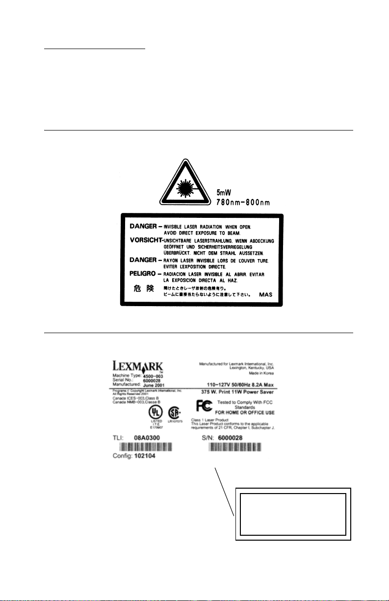
Laser notices
The following laser notice labels may be affixed to this printer as
shown:
Laser advisory label
4500
Class 1 laser statement label
CLASS 1 LASER PRODUCT
LASER KLASSE 1
LUOKAN 1 LASERLAITE
APPAREIL À LASER DE CLASSE 1
TO IEC 60825
Laser notices vii
Page 8

4500
Laser notice
The printer is certified in the U.S. to conform to the requirements of
DHHS 21 CFR Subchapter J for Class I (1) laser products, and
elsewhere is certified as a Class I laser product conforming to the
requirements of IEC 60825-1.
Class I laser products are not considered to be hazardous. The
printer contains internally a Class IIIb (3b) laser that is nominally a
5 milliwatt gallium arsenide laser operating in the wavelength region
of 770-795 nanometers. The laser system and printer are designed
so there is never any human access to laser radiation above a
Class I level during normal operation, user maintenance, or
prescribed service condition.
Laser
Der Drucker erfüllt gemäß amtlicher Bestätigung der USA die
Anforderungen der Bestimmung DHHS (Department of Health and
Human Services) 21 CFR Teil J für Laserprodukte der Klasse I (1).
In anderen Ländern gilt der Drucker als Laserprodukt der Klasse I,
der die Anforderungen der IEC (International Electrotechnical
Commission) 60825-1 gemäß amtlicher Bestätigung erfüllt.
Laserprodukte der Klasse I gelten als unschädlich. Im Inneren des
Druckers befindet sich ein Laser der Klasse IIIb (3b), bei dem es
sich um einen Galliumarsenlaser mit 5 Milliwatt handelt, der Wellen
der Länge 770-795 Nanometer ausstrahlt. Das Lasersystem und der
Drucker sind so konzipiert, daß im Normalbetrieb, bei der Wartung
durch den Benutzer oder bei ordnungsgemäßer Wartung durch den
Kundendienst Laserbestrahlung, die die Klasse I übersteigen würde,
Menschen keinesfalls erreicht.
viii Service Manual
Page 9

Avis relatif à l’utilisation de laser
Pour les Etats-Unis : cette imprimante est certifiée conforme aux
provisions DHHS 21 CFR alinéa J concernant les produits laser de
Classe I (1). Pour les autres pays : cette imprimante répond aux
normes IEC 60825-1 relatives aux produits laser de Classe I.
Les produits laser de Classe I sont considérés comme des produits
non dangereux. Cette imprimante est équipée d’un laser de Classe
IIIb (3b) (arséniure de gallium d’une puissance nominale de 5
milliwatts) émettant sur des longueurs d’onde comprises entre 770
et 795 nanomètres. L’imprimante et son système laser sont conçus
pour impossible, dans des conditions normales d’utilisation,
d’entretien par l’utilisateur ou de révision, l’exposition à des
rayonnements laser supérieurs à des rayonnements de Classe I .
Avvertenze sui prodotti laser
Questa stampante è certificata negli Stati Uniti per essere conforme
ai requisiti del DHHS 21 CFR Sottocapitolo J per i prodotti laser di
classe 1 ed è certificata negli altri Paesi come prodotto laser di
classe 1 conforme ai requisiti della norma CEI 60825-1.
4500
I prodotti laser di classe non sono considerati pericolosi. La
stampante contiene al suo interno un laser di classe IIIb (3b)
all’arseniuro di gallio della potenza di 5mW che opera sulla
lunghezza d’onda compresa tra 770 e 795 nanometri. Il sistema
laser e la stampante sono stati progettati in modo tale che le
persone a contatto con la stampante, durante il normale
funzionamento, le operazioni di servizio o quelle di assistenza
tecnica, non ricevano radiazioni laser superiori al livello della
classe 1.
Laser notices ix
Page 10

4500
Avisos sobre el láser
Se certifica que, en los EE.UU., esta impresora cumple los
requisitos para los productos láser de Clase I (1) establecidos en el
subcapítulo J de la norma CFR 21 del DHHS (Departamento de
Sanidad y Servicios) y, en los demás países, reúne todas las
condiciones expuestas en la norma IEC 60825-1 para productos
láser de Clase I (1).
Los productos láser de Clase I no se consideran peligrosos. La
impresora contiene en su interior un láser de Clase IIIb (3b) de
arseniuro de galio de funcionamiento nominal a 5 milivatios en una
longitud de onda de 770 a 795 nanómetros. El sistema láser y la
impresora están diseñados de forma que ninguna persona pueda
verse afectada por ningún tipo de radiación láser superior al nivel de
la Clase I durante su uso normal, el mantenimiento realizado por el
usuario o cualquier otra situación de servicio técnico.
Declaração sobre Laser
A impressora está certificada nos E.U.A. em conformidade com os
requisitos da regulamentação DHHS 21 CFR Subcapítulo J para a
Classe I (1) de produtos laser. Em outros locais, está certificada
como um produto laser da Classe I, em conformidade com os
requisitos da norma IEC 60825-1.
Os produtos laser da Classe I não são considerados perigosos.
Internamente, a impressora contém um produto laser da Classe IIIb
(3b), designado laser de arseneto de potássio, de 5 milliwatts
,operando numa faixa de comprimento de onda entre 770 e 795
nanómetros. O sistema e a impressora laser foram concebidos de
forma a nunca existir qualquer possiblidade de acesso humano a
radiação laser superior a um nível de Classe I durante a operação
normal, a manutenção feita pelo utilizador ou condições de
assistência prescritas.
x Service Manual
Page 11

Laserinformatie
De printer voldoet aan de eisen die gesteld worden aan een
laserprodukt van klasse I. Voor de Verenigde Staten zijn deze eisen
vastgelegd in DHHS 21 CFR Subchapter J, voor andere landen in
IEC 60825-1.
Laserprodukten van klasse I worden niet als ongevaarlijk
aangemerkt. De printer is voorzien van een laser van klasse IIIb
(3b), dat wil zeggen een gallium arsenide-laser van 5 milliwatt met
een golflengte van 770-795 nanometer. Het lasergedeelte en de
printer zijn zo ontworpen dat bij normaal gebruik, bij onderhoud of
reparatie conform de voorschriften, nooit blootstelling mogelijk is
aan laserstraling boven een niveau zoals voorgeschreven is voor
klasse 1.
Lasermeddelelse
Printeren er godkendt som et Klasse I-laserprodukt, i
overenstemmelse med kravene i IEC 60825-1.
4500
Klasse I-laserprodukter betragtes ikke som farlige. Printeren
indeholder internt en Klasse IIIB (3b)-laser, der nominelt er en 5
milliwatt galliumarsenid laser, som arbejder på bølgelængdeområdet
770-795 nanometer. Lasersystemet og printeren er udformet
således, at mennesker aldrig udsættes for en laserstråling over
Klasse I-niveau ved normal drift, brugervedligeholdelse eller
obligatoriske servicebetingelser.
Laser notices xi
Page 12

4500
Huomautus laserlaitteesta
Tämä kirjoitin on Yhdysvalloissa luokan I (1) laserlaitteiden DHHS
21 CFR Subchapter J -määrityksen mukainen ja muualla luokan I
laserlaitteiden IEC 60825-1 -määrityksen mukainen.
Luokan I laserlaitteiden ei katsota olevan vaarallisia käyttäjälle.
Kirjoittimessa on sisäinen luokan IIIb (3b) 5 milliwatin
galliumarsenidilaser, joka toimii aaltoalueella 770 - 795 nanometriä.
Laserjärjestelmä ja kirjoitin on suunniteltu siten, että käyttäjä ei
altistu luokan I määrityksiä voimakkaammalle säteilylle kirjoittimen
normaalin toiminnan, käyttäjän tekemien huoltotoimien tai muiden
huoltotoimien yhteydessä.
VARO! Avattaessa ja suojalukitus ohitettaessa olet alttiina
näkymättömälle lasersäteilylle. Älä katso säteeseen.
VARNING! Osynlig laserstrålning när denna del är öppnad och
spärren är urkopplad. Betrakta ej strålen.
Laser-notis
Denna skrivare är i USA certifierad att motsvara kraven i DHHS 21
CFR, underparagraf J för laserprodukter av Klass I (1). I andra
länder uppfyller skrivaren kraven för laserprodukter av Klass I enligt
kraven i IEC 60825-1.
Laserprodukter i Klass I anses ej hälsovådliga. Skrivaren har en
inbyggd laser av Klass IIIb (3b) som består av en laserenhet av
gallium-arsenid på 5 milliwatt som arbetar i våglängdsområdet 770795 nanometer. Lasersystemet och skrivaren är utformade så att det
aldrig finns risk för att någon person utsätts för laserstrålning över
Klass I-nivå vid normal användning, underhåll som utförs av
användaren eller annan föreskriven serviceåtgärd.
xii Service Manual
Page 13

Laser-melding
Skriveren er godkjent i USA etter kravene i DHHS 21 CFR,
underkapittel J, for klasse I (1) laserprodukter, og er i andre land
godkjent som et Klasse I-laserprodukt i samsvar med kravene i IEC
60825-1.
Klasse I-laserprodukter er ikke å betrakte som farlige. Skriveren
inneholder internt en klasse IIIb (3b)-laser, som består av en
gallium-arsenlaserenhet som avgir stråling i bølgelengdeområdet
770-795 nanometer. Lasersystemet og skriveren er utformet slik at
personer aldri utsettes for laserstråling ut over klasse I-nivå under
vanlig bruk, vedlikehold som utføres av brukeren, eller foreskrevne
serviceoperasjoner.
Avís sobre el Làser
Segons ha estat certificat als Estats Units, aquesta impressora
compleix els requisits de DHHS 21 CFR, apartat J, pels productes
làser de classe I (1), i segons ha estat certificat en altres llocs, és un
producte làser de classe I que compleix els requisits d’IEC 60825-1.
4500
Els productes làser de classe I no es consideren perillosos. Aquesta
impressora conté un làser de classe IIIb (3b) d’arseniür de gal.li,
nominalment de 5 mil.liwats, i funciona a la regió de longitud d’ona
de 770-795 nanòmetres. El sistema làser i la impressora han sigut
concebuts de manera que mai hi hagi exposició a la radiació làser
per sobre d’un nivell de classe I durant una operació normal, durant
les tasques de manteniment d’usuari ni durant els serveis que
satisfacin les condicions prescrites.
Laser notices xiii
Page 14
4500
Japanese laser notice
Chinese laser notice
xiv Service Manual
Page 15
Korean laser notice
4500
Laser notices xv
Page 16

4500
xvi Service Manual
Page 17

Safety information
• The safety of this product is based on testing and approvals of
the original design and specific components. The manufacturer
is not responsible for safety in the event of use of unauthorized
replacement parts.
• The maintenance information for this product has been
prepared for use by a professional service person and is not
intended to be used by others.
• There may be an increased risk of electric shock and personal
injury during disassembly and servicing of this product.
Professional service personnel should understand this and take
necessary precautions.
CAUTION: When you see this symbol, there is a danger
from hazardous voltage in the area of the product where
you are working. Unplug the product before you begin, or
use caution if the product must receive power in order to
perform the task.
4500
Consignes de Sécurité
• La sécurité de ce produit repose sur des tests et des
agréations portant sur sa conception d'origine et sur des
composants particuliers. Le fabricant n'assume aucune
responsabilité concernant la sécurité en cas d'utilisation de
pièces de rechange non agréées.
• Les consignes d'entretien et de réparation de ce produit
s'adressent uniquement à un personnel de maintenance
qualifié.
• Le démontage et l'entretien de ce produit pouvant présenter
certains risques électriques, le personnel d'entretien qualifié
devra prendre toutes les précautions nécessaires.
Safety information xvii
Page 18

4500
Norme di sicurezza
• La sicurezza del prodotto si basa sui test e sull'approvazione
del progetto originale e dei componenti specifici. Il produttore
non è responsabile per la sicurezza in caso di sostituzione non
autorizzata delle parti.
• Le informazioni riguardanti la manutenzione di questo prodotto
sono indirizzate soltanto al personale di assistenza autorizzato.
• Durante lo smontaggio e la manutenzione di questo prodotto,
il rischio di subire scosse elettriche e danni alla persona è più
elevato. Il personale di assistenza autorizzato, deve, quindi,
adottare le precauzioni necessarie.
Sicherheitshinweise
• Die Sicherheit dieses Produkts basiert auf Tests und
Zulassungen des ursprünglichen Modells und bestimmter
Bauteile. Bei Verwendung nicht genehmigter Ersatzteile wird
vom Hersteller keine Verantwortung oder Haftung für die
Sicherheit übernommen.
• Die Wartungsinformationen für dieses Produkt sind
ausschließlich für die Verwendung durch einen
Wartungsfachmann bestimmt.
• Während des Auseinandernehmens und der Wartung des
Geräts besteht ein zusätzliches Risiko eines elektrischen
Schlags und körperlicher Verletzung. Das zuständige
Fachpersonal sollte entsprechende Vorsichtsmaßnahmen
treffen.
xviii Service Manual
Page 19

Pautas de Seguridad
• La seguridad de este producto se basa en pruebas y
aprobaciones del diseño original y componentes específicos.
El fabricante no es responsable de la seguridad en caso de uso
de piezas de repuesto no autorizadas.
• La información sobre el mantenimiento de este producto está
dirigida exclusivamente al personal cualificado de
mantenimiento.
• Existe mayor riesgo de descarga eléctrica y de daños
personales durante el desmontaje y la reparación de la
máquina. El personal cualificado debe ser consciente de este
peligro y tomar las precauciones necesarias.
Informações de Segurança
• A segurança deste produto baseia-se em testes e aprovações
do modelo original e de componentes específicos. O fabricante
não é responsável pela segunrança, no caso de uso de peças
de substituição não autorizadas.
• As informações de segurança relativas a este produto
destinam-se a profissionais destes serviços e não devem ser
utilizadas por outras pessoas.
• Risco de choques eléctricos e ferimentos graves durante a
desmontagem e manutenção deste produto. Os profissionais
destes serviços devem estar avisados deste facto e tomar os
cuidados necessários.
4500
Safety information xix
Page 20
4500
Informació de Seguretat
• La seguretat d'aquest producte es basa en l'avaluació i
aprovació del disseny original i els components específics.
El fabricant no es fa responsable de les qüestions de
seguretat si s'utilitzen peces de recanvi no autoritzades.
• La informació pel manteniment d’aquest producte està
orientada exclusivament a professionals i no està destinada
a ningú que no ho sigui.
• El risc de xoc elèctric i de danys personals pot augmentar
durant el procés de desmuntatge i de servei d’aquest producte.
El personal professional ha d’estar-ne assabentat i prendre
les mesures convenients.
xx Service Manual
Page 21
4500
Safety information xxi
Page 22

4500
Preface
This manual contains maintenance procedures for service
personnel. It is divided into the following chapters:
1. General Information contains a general description of the
printer and the maintenance approach used to repair it. Special
tools and test equipment are listed in this chapter, as well as
general environmental and safety instructions.
2. Diagnostic Information contains an error indicator table,
symptom tables, and service checks used to isolate failing field
replaceable units (FRUs).
3. Diagnostic Aids contains tests and checks used to locate or
repeat symptoms of printer problems.
4. Repair Information provides instructions for making printer
adjustments and removing and installing FRUs.
5. Connector Locations uses illustrations to identify the
connector locations and test points on the printer.
6. Preventive Maintenance contains the lubrication specifications
and recommendations to prevent problems.
7. Parts Catalog contains illustrations and part numbers for
individual FRUs.
Definitions
Note: A note provides additional information.
Warning: A warning identifies something that might damage the
printer hardware or software.
CAUTION: A caution identifies something that might cause a
servicer harm.
CAUTION: When you see this symbol, there is a danger
from hazardous voltage in the area of the product where
you are working. Unplug the product before you begin, or
use caution if the product must receive power in order to
perform the task.
xxii Service Manual
Page 23

1. General information
The Lexmark™ E220/E32x series are letter–quality laser page
monochrome desktop printers designed to fit into space critical
environments and yet not sacrifice speed or ease of use. The
E220/E32x attaches to an IBM Personal Computer or other
computers compatible with the IBM Personal Computer (with 386
processor or higher) and Macintosh Computers via the Universal
Serial Bus (USB) connection.
4500
General information 1-1
Page 24
4500
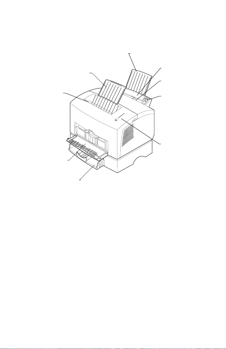
Six printer models are available:
Models E320/E322
Rear paper support
Front paper suppor t
Top output bin
Front output door
Optional 250-sheet tray
Tray 1
Manual feed
Paper guide
Operator panel
lights
• Lexmark E320 printer with 4MB of standard memory
• Lexmark E322 printer with 8MB of standard memory
• Lexmark E322n printer with standard Ethernet and
16MB of standard memory
1-2 Service Manual
Page 25
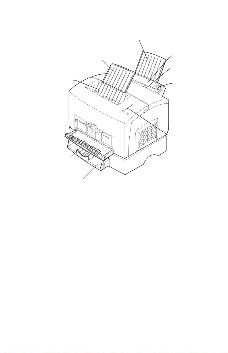
Models E220/E321/E323
4500
Rear paper support
Front paper support
Top output bin
Front output door
Optional 250-sheet tray
Tray 1
Manual feed
Paper guide
Operator panel
lights
• Lexmark E220 printer with 8MB of standard memory
• Lexmark E321 printer with 8MB of standard memory
• Lexmark E323 printer with 16MB of standard memory
• Lexmark E323n printer with 16MB of standard memory and
standard Ethernet
General information 1-3
Page 26

4500
There are some apparent differences in the E320/E322 series and
the E220/E321/E323 series. The E220/E321/E323 series has:
• a dark color in most geographies
• two buttons on the operator panel
• a bulge on the right side cover
Internally, the E220/E321/E323 series has:
• a combined engine and RIP card
• a different printhead and interlock switch
• a different fuser
• a different print cartridge
• Nonvolatile random access memory (NVRAM) located on the
operator panel printed circuit board (PCB)
• higher speed pages per minute (ppm).
The E220 is similar to the E321 but has a slower speed.
Other differences are listed in the following table.
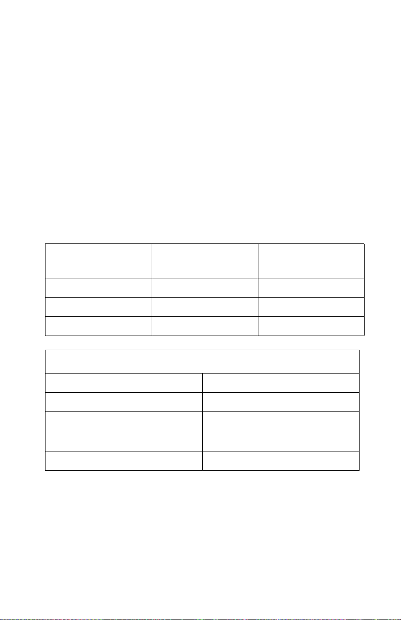
Model differences
E220 E320 E321 E322 E322n E323 E323n
MT/
model
Base
memory
Compatibility
PCL® PCL 5e PCL 5e PCL 5e PCL 6 PCL 6 PCL 6 PCL 6
4500–
101
8MB 4MB 8MB 8MB 16MB 12MB 16MB
MAC;
OS
support
+ HBP
4500–
001
MAC;
OS
support
4500–
201
MAC;
OS
support
+ HBP
4500–
002
MSQ;
MAC;
Linux;
OS
support
/ PS3
4500–
003
MSQ;
MAC;
Linux;
OS
support
/ PS3
4500–
202
MSQ;
MAC;
Linux;
OS
support
/+HBP;
PS3
4500–
213
MSQ;
MAC;
Linux;
OS
support
/+HBP;
PS3
1-4 Service Manual
Page 27
Printer operation
Paper is held in a 150 page tray where it is picked by a center–fed D
shape pick roller. The paper follows an L shape path as it moves
through the printer. Images are created with toner on an optical
photoconductor (OPC) drum within the toner cartridge. A transfer
roller then draws the toner off the OPC drum onto the paper. Once
the toner is affixed to the paper by the fuser, the paper exits either
the top or front of the printer.
Printer dimensions and clearance
The following table contains the dimensions for each printer model.
This does not include packaging but does include the print cartridge
that ships with the printer.
4500
Physical dimensions E320/E322/E322n
Height 221 mm (8.7 inches) 221 mm (8.7 inches)
Width 380 mm (15.0 inches) 391 mm (15.4 inches)
Depth 368 mm (14.5 inches) 368 mm (14.2 inches)
Operating clearance
Top 203 mm (8 inches)
Left and right sides 305 mm (12 inches)
Front 152 mm (6 inches)
None required except for paper
ejection.
Rear 51 mm (2 inches)
E220/E321/
E323/E323n)
Note: Do not enclose printer on all sides without providing
ventilation.
General information 1-5
Page 28

4500
Options
The following options are available for the Lexmark E220/E32x.
Note: Some options are not available in every country. Contact your
point of purchase for options available in your country.
Option E220 E320 E321 E322 E322n E323 E323n
Tray 2 A va i l -
Memory
To t al
possible
Flash N/A N/A N/A 1, 2,
able
8MB,
16MB,
32MB,
64MB
72MB 68MB 72MB 72MB 80MB 144MB 144MB
Available
8MB,
16MB,
32MB,
64MB
Available
8MB,
16MB,
32MB,
64MB
Available
8MB,
16MB,
32MB,
64MB
4MB
Note:
– N/A means not available
– Standard random access memory (RAM) is soldered on the
controller card on both the E320/E322n and
E220/E321/E323n.
Available
8MB,
16MB,
32MB,
64MB
1, 2,
4MB
Available
8MB,
16MB,
32MB,
64MB
2, 4, 8,
16MB
Available
8MB,
16MB,
32MB,
64MB
2, 4, 8,
16MB
1-6 Service Manual
Page 29

Acronyms
ASF Auto Sheet Feed
ASIC Application-Specific Integrated Circuit
B/M Bill of Material
CRC Cyclic Redundancy Check
CRLF Carriage Return Line Feed
DIMM Dual Inline Memory Module
DRAM Dynamic Random Access Memory
ENA External Network Adapter
ESD Electrostatic Discharge
FRU Field Replaceable Unit
HBP Host Based Printing
HVPS High Voltage Power Supply
LASER Light Amplification by Stimulated Emission of
Radiation
LED Light–Emitting Diode
LFCR Line Feed Carriage Return
LVPS Low Voltage Power Supply
NAND Not AND
NVRAM Nonvolatile Random Access Memory
OPC Optical Photoconductor
PC Photoconductor
PCB Printed Circuit Board
PCL Printer Command Language
PJL Printer Job Language
PPM Pages Per Minute
POR Power–On Reset
POST Power–On Self Test
PPDS Personal Printer Data Stream
PSU Power Supply Unit
PWM Pulse Width Modulation
RAM Random Access Memory
ROM Read Only Memory
SIMM Single Inline Memory Module
SRAM Static Random Access Memory
THM Thermistor
USB Universal Serial Bus
V ac Volts alternating current
V dc Volts direct current
4500
General information 1-7
Page 30

4500
1-8 Service Manual
Page 31

4500–E320/E322
2. Diagnostic information
Start
Diagnostics (E320/E322)
Note: For diagnostic information about models
E220/E321/E323 see “Diagnostics (E220/E321/E323) ” on
page 2-35 for more information.
CAUTION: NEVER manually actuate or disable the top cover
interlock switch and the printhead shutter actuator at
the same time.
To perform some of the service checks and tests, such as troubleshooting
paper feed problems, you need to actuate the top cover interlock switch
with the covers open or removed and power applied to the machine. It is
important for personal safety that you DO NOT, FOR ANY REASON,
disable the printhead shutter actuator when power is on.
Unplug power from the printer before connecting or disconnecting any
cable or electronic board or assembly for personal safety and to prevent
damage to the printer.
Use the service error code, user error message, symptom table, service
checks, and diagnostic aids in this chapter to determine the corrective
action necessary to repair a malfunctioning printer.
The lights on the operator panel can indicate either a user error message
or service error message. When a service error occurs, the printer stops
printing and all operator panel lights blink in a continuous pattern, indicating
a service error, until the printer is powered off. If all operator panel lights are
blinking, go to the “Service error codes ” on page 2-11 for more
information.
When a user error message occurs, one or more operator panel lights are
on solid or blinking. See “Status information ” on page 2-3 for more
information.
If the machine does not have a service error code and does not complete
power–on self test (POST), go to the “POST symptom table ” on
page 2-32. If the machine completes POST without an error, and there is a
symptom, go to the “Printer symptom table ” on page 2-33. Locate the
symptom and take the appropriate action.
Diagnostic information 2-1
Page 32

4500–E320/E322
If a service error code appears while working on the machine, go to
the “Service error codes ” on page 2-11 and take the appropriate
action.
Operator panel
The E320/E322 operator panel consists of six indicator lights and
one button. The information provided by the six lights is classified
into three groups:
• Status
• Attendance
• Service
Depending on the light sequence, briefly (approximately one
second) push the operator panel button to restart the printer, display
an error code, or activate other printer functions.
The operator panel light table (see page 2-3) can be used to
determine the type of message displayed based on which
combination of lights are on or flashing.
2-2 Service Manual
Page 33

4500–E320/E322
Status information
The following symbols are used in the status, attendance, and
service information tables:
Operator
panel
lights
● Operator panel light is on.
❍ Operator panel light is off.
✳ Operator panel light is blinking.
Description
✕ Operator panel light is blinking
slowly.
Ready
The printer is in a Ready state.
Ready indicates the printer is ready to receive and process data
from the host system.
• Brief button press executes a print test.
• Long button press executes a printer reset.
Diagnostic information 2-3
Page 34

4500–E320/E322
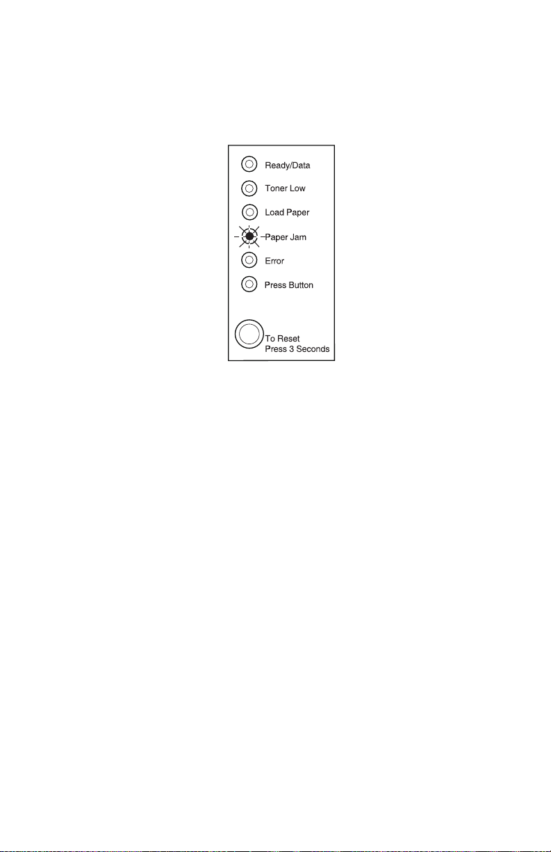
Attendance information
When attendance information is displayed, the user is required to
open the printer cover and clear all paper from the paper path. The
user indicates the jam is cleared by closing the cover or by
performing a brief button press.
Paper jam
A paper jam is detected.
• Brief button press assumes the jam has been cleared.
A warm–up is performed, and the print job resumes.
• Long button press is ignored.
• Open/close cover assumes the jam has been cleared.
A warm–up is performed, and the job prints.
2-4 Service Manual
Page 35

4500–E320/E322
Host interface error
This error is generated when the printer detects an error
communicating with the host computer. There are three causes of
this error:
1. Parallel external network adapter (ENA) connection is lost
during the printer’s power–on cycle. Once a connection is
initially established, a printer setting is modified to note that the
connection exists. Then, each time the power is cycled on the
printer, if the setting states a connection exists, the printer
attempts to communicate with the adapter. If the adapter does
not respond, a message is posted.
This error is only detected during the power–on cycle. This
means if the external network adapter connection is lost after
the power–on cycle is complete, this error is not detected. The
printer cannot distinguish between an adapter which is quiet, for
example, not sending any data, and an adapter which has been
disconnected.
Diagnostic information 2-5
Page 36

4500–E320/E322
2. Standard parallel port disabled – this error is generated when
the host computer attempts to communicate with the printer
through the standard parallel port. However, the parallel port
has been disabled either through the printer configuration
mode, or through the MarkVision™ host utility
3. Standard USB port disabled – this error is generated when the
host computer attempts to communicate with the printer through
the standard USB port. However, the USB port has been
disabled either through the printer configuration mode, or
through the MarkVision host utility.
The error recovery process for this error is:
1. If this error occurs at power–on and an ENA is attached to the
printer, verify the ENA is properly connected.
2. When the printer is in the Ready state, press the operator panel
button to print a menus settings page.
3. Under the “parallel menu”, look for the “parallel buffer” line. If
this line says “disabled” and the host computer is trying to print
using the parallel port, re–enable the parallel port using
MarkVision or the printers configuration mode.
4. Under the “USB menu”, look for the “USB buffer” line. If this line
says “disabled” and the host computer is trying to print using the
USB port, re–enable the USB port using MarkVision or the
printer configuration mode.
See “Configuration mode ” on page 3-14 for information using the
printer configuration mode to enable a disabled port.
2-6 Service Manual
Page 37

4500–E320/E322
Service information
There are three levels of service code information.
• Primary service error codes
• Secondary service error codes
• Subcodes (sub set of the secondary codes)
Service information is displayed whenever the printer is in the check
state, and needs servicing. In general, service errors are not
recoverable. However, it may be possible to turn the printer off and
back on to temporarily recover from the error condition if it is
intermittent.
When a service error occurs, the printer stops printing immediately.
The only recovery is to turn off the printer.
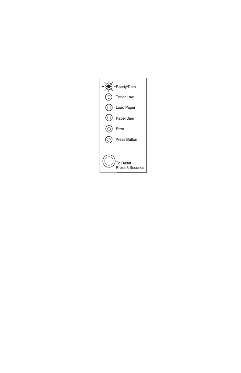
The following operator panel is an example indicating a primary
service error code condition.
• Brief button press displays a service error code pattern.
• Long button press displays a service error code pattern.
• Double button press is not available.
• Open/close cover is ignored.
Diagnostic information 2-7
Page 38

4500–E320/E322
Primary service error codes
When a service error occurs, the printer stops printing and all
operator panel lights blink in a continuous pattern, indicating a
service error, until the printer is turned off.
Press and release the operator panel button to display the
secondary service error code.
2-8 Service Manual
Page 39

4500–E320/E322
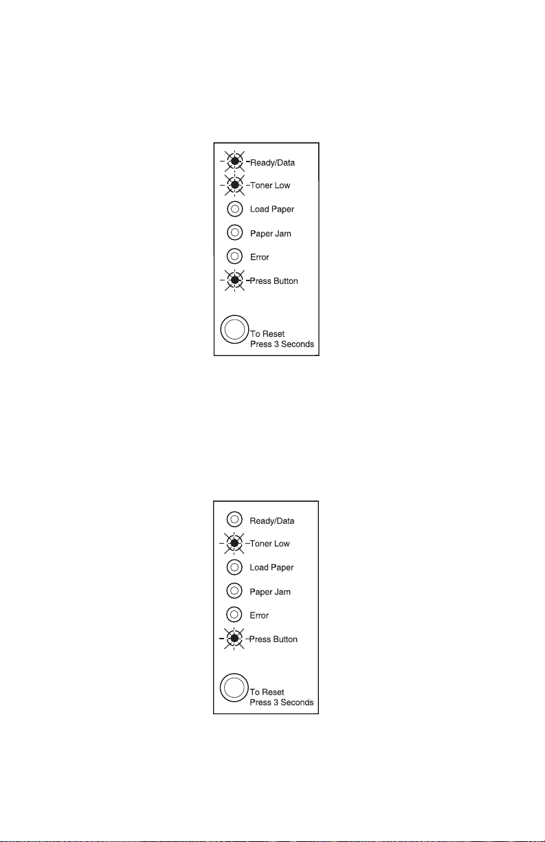
Secondary service error codes
The operator panel button has been pushed and a secondary
service error has occurred indicating a fuser failure.
Once the error code is displayed, and if the operator panel button is
pushed again, the operator panel displays the service error
indication (all six indicator lights blinking). Continual pressing of the
button causes the lights to repeat in the following order:
1. Service error indication
2. Fuser service error code indication
3. Service error indication
Diagnostic information 2-9
Page 40

4500–E320/E322
Subcode service error code
Pressing the operator panel button again, indicates a fuser failure–
under temperature subcode.
Once the subcode is displayed, if the operator panel button is
pushed again, all six indicator lights blink. Continual pressing of the
operator panel button causes the lights to repeat in the following
order:
1. Service error indication
2. Fuser failure service error code indication
3. Fuser failure–under temperature service error subcode
indication
4. Service error indication
2-10 Service Manual
Page 41
4500–E320/E322
Service error codes
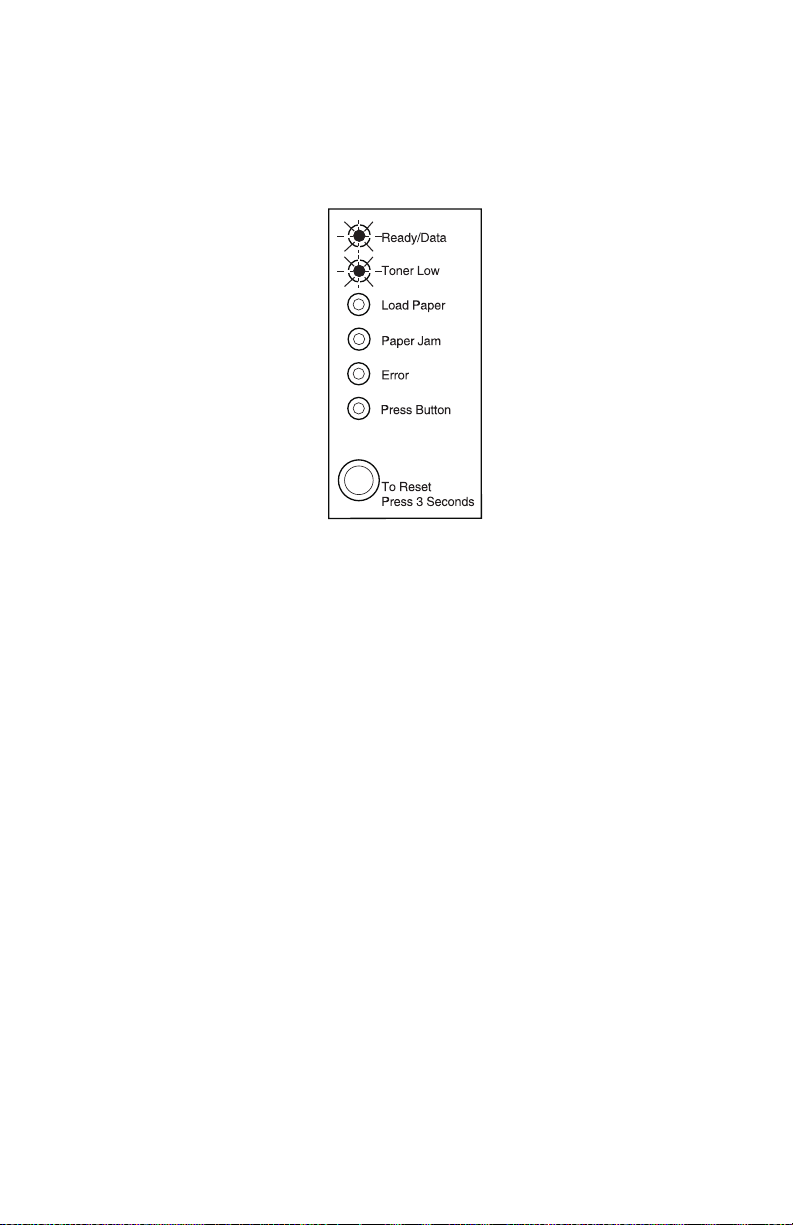
Software service error code
The operator panel button has been pushed and a secondary
service error has occurred indicating a software error.
Once the error code is displayed, if the operator panel button is
pushed again, the operator panel will display the service error
indication (all six indicator lights blinking). Continual pressing of the
operator panel button causes the lights to repeat in the following
order:
1. Service error indication
2. Software service error code indication
3. Service error indication
Place the printer into the special function menu and run a print test.
See “Using the special function menu (E320/E322) ” on
page 2-105 for more information. If the printer does not run printer
diagnostics, replace the controller card.
Diagnostic information 2-11
Page 42
4500–E320/E322
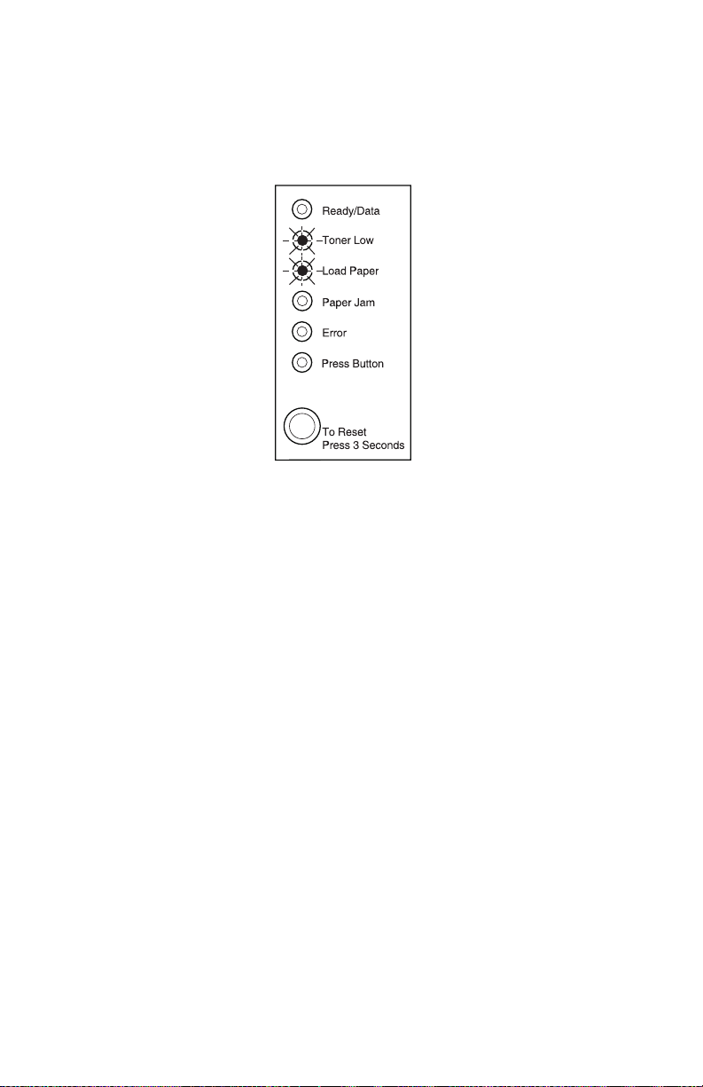
Fuser failure–over temperature error code
The operator panel is indicating a fuser failure–over temperature
subcode.
See “Hot fuser service check ” on page 2-76 for more
information.
Fuser failure–under temperature error code
The operator panel is indicating a fuser failure–under temperature
subcode.
See “Hot fuser service check ” on page 2-76 for more
information.
2-12 Service Manual
Page 43

4500–E320/E322
Fuser failure–under temperature error code–standby
The operator panel is indicating a fuser failure–under temperature
subcode.
See “Hot fuser service check ” on page 2-76 for more
information.
Fuser failure–under temperature error code–while printing
The operator panel is indicating a fuser failure–under temperature
subcode. See “Hot fuser service check ” on page 2-76 for more
information.
Diagnostic information 2-13
Page 44

4500–E320/E322
Fuser failure–thermistor open error code
The operator panel is indicating a fuser failure–thermistor open
subcode.
Replace the fuser assembly.
2-14 Service Manual
Page 45
4500–E320/E322
Mirror motor failure service error code
The operator panel button has been pushed and a mirror motor
failure service error has occurred.
Once the error code is displayed, if the operator panel button is
pushed again, the operator panel displays the service error
indication (all six indicator lights blinking). Continual pressing of the
operator panel button causes the lights to repeat in the following
order:
1. Service error indication
2. Mirror motor failure service error code indication
3. Service error indication
Inspect the printhead cable and replace the assembly as necessary.
If this does not correct the problem, replace the engine/low voltage
power supply (LVPS) board.
Diagnostic information 2-15
Page 46
4500–E320/E322
Optional memory service error code
The operator panel button has been pushed and a memory service
error has occurred.
Once the error code is displayed, if the operator panel button is
pushed again, the operator panel displays the service error
indication (all six indicator lights blinking). Continual pressing of the
operator panel button causes the lights to repeat in the following
order:
1. Service error indication
2. Optional memory service error code indication
3. Service error indication
Replace the optional memory, dual inline memory module
this does not correct the problem, replace:
• The code overlay
• Read only memory (ROM)
• Flash single inline memory module (SIMM) or
• The controller card.
2-16 Service Manual
(DIMM). If
Page 47
4500–E320/E322
ROM checksum failure service error code
The operator panel button has been pushed and a ROM checksum
failure service error has occurred.
Once the error code is displayed, if the operator panel button is
pushed again, the operator panel displays the service error
indication (all six indicator lights blinking). Continual pressing of the
operator panel button causes the lights to repeat in the following
order:
1. Service error indication
2. ROM checksum failure service error code indication
3. Service error indication
Replace the ROM SIMM. If this does not correct the problem,
replace the controller card.
Diagnostic information 2-17
Page 48

4500–E320/E322
Base memory service error code
The operator panel button has been pushed and a base memory
service error has occurred.
Once the error code is displayed, if the operator panel button is
pushed again, the operator panel will display the service error
indication (all six indicator lights blinking). Continual pressing of the
operator panel button causes the lights to repeat in the following
order:
1. Service error indication
2. Base memory service error code indication
3. Service error indication
Replace the controller card.
2-18 Service Manual
Page 49

NVRAM failure service error code
4500–E320/E322
The operator panel button has been pushed and a
access memory (
NVRAM) failure service error has occurred.
nonvolatile random
Once the error code is displayed, if the operator panel button is
pushed again, the operator panel displays the service error
indication (all six indicator lights blinking). Continual pressing of the
operator panel button causes the lights to repeat in the following
order:
1. Service error indication
2. NVRAM failure service error code indication
3. Service error indication
Replace the engine board.
Diagnostic information 2-19
Page 50

4500–E320/E322
ASIC register failure service error code
The operator panel button has been pushed and an
application–specific integrated circuit ASIC register failure service
error has occurred.
Once the error code is displayed, if the operator panel button is
pushed again, the operator panel displays the service error
indication–all six indicator lights blinking. Continual pressing of the
operator panel button causes the lights to repeat in the following
order:
1. Service error indication
2. ASIC register failure service error code indication
3. Service error indication
Replace the controller card.
2-20 Service Manual
Page 51

4500–E320/E322
ASIC static random access memory (SRAM) failure service error
code
The operator panel button has been pushed and an ASIC SRAM
failure service error has occurred.
Once the error code is displayed, if the operator panel button is
pushed again, the operator panel displays the service error
indication (all six indicator lights blinking). Continual pressing of the
operator panel button causes the lights to repeat in the following
order:
1. Service error indication
2. ASIC SRAM failure service error code indication
3. Service error indication
Replace the controller card.
Diagnostic information 2-21
Page 52

4500–E320/E322
Flash memory failure service error code
The operator panel button has been pushed and a flash memory
failure service error has occurred.
Once the error code is displayed, if the operator panel button is
pushed again, the operator panel displays the service error
indication (all six indicator lights blinking). Continual pressing of the
operator panel button causes the lights to repeat in the following
order:
1. Service error indication
2. Flash memory failure service error code indication
3. Service error indication
Replace the flash memory. If this does not correct the problem,
replace the controller card.
2-22 Service Manual
Page 53

4500–E320/E322
Font checksum failure service error code
The operator panel button has been pushed and a font checksum
failure service error has occurred.
Once the error code is displayed, if the operator panel button is
pushed again, the operator panel displays the service error
indication (all six indicator lights blinking). Continual pressing of the
operator panel button causes the lights to repeat in the following
order:
1. Service error indication
2. Font checksum failure service error code indication
3. Service error indication
Replace the ROM SIMM. If this does not correct the problem,
replace the controller card.
Diagnostic information 2-23
Page 54

4500–E320/E322
Engine communication failure service error code
The operator panel button has been pushed and an engine
communication failure service error has occurred.
Once the error code is displayed, if the operator panel button is
pushed again, the operator panel displays the service error
indication (all six indicator lights blinking). Continual pressing of the
operator panel button causes the lights to repeat in the following
order:
1. Service error indication
2. Engine communication failure service error code indication
3. Service error indication
Replace the engine board.
Error codes/conditions not detected or reported
The printer does not detect or report the following conditions/errors:
• Incorrect manual feed
• Output bin full
• Print cartridge missing (reported as “top cover open” error)
2-24 Service Manual
Page 55

Operator panel light summary table
Operator
panel
light
● Operator panel light is on.
❍ Operator panel light is off.
✳ Operator panel light is blinking.
Description
4500–E320/E322
✕ Operator panel light is blinking
slowly.
Diagnostic information 2-25
Page 56

4500–E320/E322
Error code table
Ready
/Data
Toner
Low
Load
Paper
Paper
Jam
Error
Press
Button
Condition
● ❍ ❍❍❍ ❍Ready
● ❍ ❍❍❍ ✳Demo ready
❍ ❍❍❍❍ ●Offline
(remote)
✳ ❍❍❍❍ ❍Busy
● ❍ ❍❍❍ ●Waiting
● ●●●● ●• Restoring
factory
defaults
• Saving
settings
• Resetting
printer
✳ ❍❍❍✳ ❍Flushing
buffer
✕ ❍❍❍❍ ❍Hex Trace
❍❍❍●❍❍Paper jam
❍❍✳❍❍●Load manual
paper/
envelope
❍❍●❍❍●Load paper/
envelope
Tray 1 o r
Tray 2
❍❍●❍❍✳Load paper
Tray 1 for
side 2 of
manual
duplex
❍❍❍❍● ❍Top c over
open
2-26 Service Manual
Page 57

4500–E320/E322
Ready
/Data
Tone r
Low
Load
Paper
Paper
Jam
Error
Press
Button
Condition
❍✳❍❍● ❍Toner
cartridge
error
❍❍❍❍●●Printer error
❍❍❍❍✳●Flash
memory full
❍❍●●❍❍Diagnostic
test mode
Operator panel lights when toner is low
●●❍❍❍❍Ready and
Toner Low
●●❍❍❍✳Demo ready
and toner low
❍●❍❍❍●Offline
(remote) and
toner low
✳●❍❍❍❍Busy and
toner low
●●❍❍❍●Waiting and
toner low
●●●●●●• Restoring
factory
defaults
• Saving
settings
• Resetting
printer and
toner low
✳●❍❍✳❍Flushing
buffer and
toner low
✕●❍❍❍❍Hex Trace
and toner low
Diagnostic information 2-27
Page 58

4500–E320/E322
Ready
/Data
Toner
Low
Load
Paper
Paper
Jam
Error
Press
Button
Condition
❍●❍● ❍❍Paper jam
and toner low
❍●✳ ❍❍●Load manual
paper/
envelope and
toner low
❍●●❍❍●Load paper/
envelope
Tray 1 and
toner low
❍●●❍❍✳Load paper
Tray 1 for
side 2 of
manual
duplex and
toner low
❍●✕❍❍●Load paper
Tray 2 and
toner low
❍●❍❍● ❍To p c o ver
open and
toner low
❍✳❍❍● ❍Tone r
cartridge
error
❍●❍❍● ●Printer error
and toner low
❍● ❍❍✳ ●Flash
memory full
and toner low
❍●●●❍❍Diagnostic
test mode
and toner low
Printer error secondary codes
●●❍❍●●Memory full
2-28 Service Manual
Page 59

4500–E320/E322
Ready
/Data
Tone r
Low
Load
Paper
Paper
Jam
Error
Press
Button
Condition
●❍❍❍●●Complex
page
●❍●❍●●Short paper
●●●❍●●Toner low
intervention
✳✳❍❍●●Resolution
reduction
warning
❍✳❍❍● ●Font error
✳❍❍❍●●Resource
save off–
deficient
memory
❍❍✳❍● ●Insufficient
defrag
memory
❍ ❍❍✳ ● ●Host
interface
error (parallel
ENA
connection
lost, standard
parallel port
disabled,
standard
USB port
disabled)
Diagnostic information 2-29
Page 60

4500–E320/E322
Ready
/Data
Toner
Low
Load
Paper
Paper
Jam
Error
Press
Button
Condition
Service error codes
For some service error codes, a second service error code is used to
further describe the error. When a service error occurs, pressing the
operator panel button after viewing the primary service error code displays
the secondary service error code. The following table contains the
secondary service error codes.
Primary service error codes
✳✳✳✳✳✳Service error,
see
page 2-8.
Secondary service error codes
✳ ❍❍❍❍ ❍Software
error see
page 2-11.
❍ ✳ ❍❍❍ ❍Fuser failure
see
page 2-12.
✳ ✳ ❍❍❍ ❍Mirror motor
failure see
page 2-15.
❍✳✳❍❍ ❍Optional
❍❍❍✳❍❍ROM
✳❍❍✳❍❍Base
❍✳❍✳❍❍NVRAM
2-30 Service Manual
memory see
page 2-16.
checksum
see
page 2-17.
memory see
page 2-18.
failure see
page 2-19.
Page 61

4500–E320/E322
Ready
/Data
Tone r
Low
Load
Paper
Paper
Jam
Error
Press
Button
Condition
✳✳❍✳❍❍ASIC register
failure see
page 2-20.
❍❍✳✳❍❍ASIC SRAM
failure see
page 2-21.
✳❍✳✳❍❍Flash
memory
failure see
page 2-22.
❍✳✳✳ ❍❍Font
checksum
see
page 2-23.
✳✳✳✳❍❍Engine
communica–
tion failure
see
page 2-24.
Fuser service error subcodes
✳✳❍❍❍✳Fuser
failure–over
temperature
see
page 2-12.
❍✳❍❍❍✳Fuser
failure–under
temperature
see
page 2-12.
❍❍✳❍❍✳Fuser
failure–
thermistor
open see
page 2-14.
Diagnostic information 2-31
Page 62

4500–E320/E322
POST
When you turn the printer on, it performs a power–on self test.
Check for correct POST functioning of the base printer by observing
the following:
Symptom tables
POST symptom table
Symptom Action
The main motor, cooling fan,
and fuser do not come on.
POST completes except one or
more lights do not come on.
None of the lights come on. See the “Operator panel service
Main motor does not come on. See the “Main motor service check ”
Fan does not come on. See the “Cooling fan service check
Fuser lamp does not come on. See the “Cold fuser service check ”
Fuser lamp never turns off. See the “Hot fuser service check ”
The paper feed picks and tries
to feed paper.
See the “Cover interlock switch
service check (E320/E322) ” on
page 2-69.
See the “Main motor service check ”
on page 2-77.
check ” on page 2-79.
on page 2-77.
(E320/E322) ” on page 2-65.
on page 2-64.
on page 2-76.
See the “Paper feed service checks ”
on page 2-81.
2-32 Service Manual
Page 63

Printer symptom table
Symptom Action
4500–E320/E322
Dead machine (no power) See the “Dead machine service
Fan noisy or not working See the “Cooling fan service check
Fuser parts melted See the “Hot fuser service check ” on
Fuser lamp doesn’t light See the “Hot fuser service check ” on
Toner not fused to the paper See the “Hot fuser service check ” on
Main motor noisy or not moving See the “Main motor service check ”
Paper skew See the “Paper feed service checks ”
Printer not communicating with
host
Top cover will not close See the “Cover interlock switch
check ” on page 2-71.
(E320/E322) ” on page 2-65 or
“Cooling fan service check (E220/
E321/E323) ” on page 2-66.
page 2-76.
page 2-76.
page 2-76.
on page 2-77.
on page 2-81.
See the “Parallel port service check ”
on page 2-85.
service check (E320/E322) ” on
page 2-69 or “Cover interlock switch
service check (E220/E321/E323) ” on
page 2-70.
Operator panel button not
responding
Operator panel lights do not
light or very dim
Blank page See the “Blank page ” on page 2-86.
Black page See the “Black page ” on page 2-87.
Heavy background See the “Heavy background ” on
Light print See the “Light print ” on page 2-90.
See the “Operator panel button
service check ” on page 2-78.
See the “Operator panel service
check ” on page 2-79.
page 2-88.
Diagnostic information 2-33
Page 64

4500–E320/E322
Symptom Action
White or black lines or bands See the “White or black lines or
bands ” on page 2-91.
Toner on back of page See the “Toner on back of page ” on
Paper jams See the “Paper feed service checks ”
Paper never picks See the “Paper never picks ” on
Paper feeds continuously See the “Paper picks during POST
Paper wrinkled or bent See the “Paper “trees,” wrinkles,
page 2-91.
on page 2-81.
page 2-83.
and/or continuously ” on page 2-81.
stacks poorly or curls ” on
page 2-84.
2-34 Service Manual
Page 65

4500–E220/E321/E323
Diagnostics (E220/E321/E323)
Note: For diagnostic information about models E320/E323 see
“Diagnostics (E320/E322) ” on page 2-1 for more
information.
CAUTION:
or disconnecting any cable, assembly, or electronic card. This
is a precaution for personal safety and to prevent damage to
the printer.
The lights on the operator panel indicate the status of the printer
anytime it is powered on. When the printer experiences a problem
requiring operator intervention, it indicates the source by blinking
one or more lights. See “Status information light patterns ” on
page 2-38 for more information. When all six lights blink
simultaneously, a service may need to be performed. See “Service
error codes ” on page 2-45 for more information.
If the printer does not indicate a service error code nor complete
POST without an error but there is a symptom, see “Symptom
tables ” on page 2-60 for more information.
Unplug power from the printer before connecting
Diagnostic information 2-35
Page 66

4500–E220/E321/E323
Operator panel
The operator panel consists of six indicator lights and two buttons.
Ready/Data
Toner Low
Load Paper
Paper Jam
Error
Press Continue
Continue
Cancel
Note: Traditional printer settings such as paper source, paper size,
and orientation may not be selected or modified using the
operator panel with the exception that U.S. versus non–U.S.
may be chosen in the diagnostic mode. Users must either
utilize an application print driver and/or the printer toolkit to
modify settings.
The operator panel may be used for:
• Determining printer status (See “Status information light
patterns ” on page 2-38 for more information.)
• Reviewing printer settings (See “Power–On Self Test (POST) ”
on page 2-60 for more information.)
• Changing printer settings (See “Power–on operations ” on
page 2-59 for more information.)
• Utilizing diagnostic tools (See “Power–on operations ” on
page 2-59 for more information.)
• Obtaining information about printer service errors (See
“Service error codes ” on page 2-45 for more information.)
2-36 Service Manual
Page 67

4500–E220/E321/E323
Light patterns
The following symbols are used in the status, attendance, and
service information tables.
Operator
panel
light
● Operator panel light is on.
❍ Operator panel light is off.
✳ Operator panel light is blinking.
Description
✕ Operator panel light is blinking
slowly.
Diagnostic information 2-37
Page 68

4500–E220/E321/E323
Status information light patterns
Status
Ready/Data
● ❍❍❍❍❍Ready
● ❍❍❍❍✳Demo ready
✕ ❍❍❍❍❍Hex Trace ready
✳ ❍❍❍❍❍Busy
●❍❍❍❍●Waiting
●● ❍❍❍❍Ready, with toner low warning
●● ❍❍❍✳Demo ready, with toner low
✕● ❍❍❍❍Hex Trace ready, with toner low
✳ ● ❍❍❍❍Busy, with toner low warning
●●❍❍❍●Waiting, with toner low warning
✳❍❍❍✳❍Flushing
●●●●●●Canceling job / resetting printer
Toner Low
Load/Remove Paper
All lights cycling Restarting printer
Paper Jam
Error
Press Continue
warning
warning
/activating changes
❍❍●● ❍❍Diagnostics–memory test
●●●❍❍❍Programming system code–
DO NOT POWER OFF
Note: The Error and Press
Continue lights cycle
through four different
patterns to indicate
progress during
programming.
2-38 Service Manual
Page 69

4500–E220/E321/E323
Status
Ready/Data
Toner Low
Load/Remove Paper
Paper Jam
Error
Press Continue
✳✳✳❍❍❍Programming system code
● ❍❍❍● ❍Invalid engine code / invalid
partially complete–download
system code data
network code
Note: A double press of
Continue, causes a
secondary light pattern
which indicates further
information on the type
of invalid code status
exists. See “Invalid
code secondary light
patterns ” on
page 2-40.
Diagnostic information 2-39
Page 70
4500–E220/E321/E323
Invalid code secondary light patterns
Status
Ready/Data
●❍●❍●❍Invalid engine code
●❍✳❍●❍Invalid network code
Toner Low
Load/Remove Paper
Paper Jam
Error
Press Continue
Paper Jam secondary light patterns
Attendance Condition
Ready/Data
● ❍❍● ❍●Paper jam–input sensor
❍● ❍● ❍●Paper jam–exit sensor
❍✳ ❍● ❍●Paper jam–duplex sensor
❍❍●● ❍●Paper jam–fuser exit sensor
✳ ❍❍● ❍●Paper jam–multipurpose
Toner Low
Load/Remove Paper
Paper Jam
Error
Press Continue
feeder sensor
2-40 Service Manual
Page 71

4500–E220/E321/E323
Printer error secondary light patterns
To obtain the secondary light pattern, quickly press Continue twice.
Attendance Condition
Ready/Data
Toner Low
Load/Remove Paper
Paper Jam
● ❍❍❍● ●Complex page
❍● ❍❍● ●Insufficient collation area
❍❍● ❍●●Defective flash
❍❍❍●●●Network interface error
Error
Press Continue
✳ ❍❍❍●●Resource save off–deficient
❍✳ ❍❍●●Personal printer data stream
❍❍✳❍●●Insufficient defrag memory
❍❍❍✳● ●ENA connection lost
●●❍❍●●Memory full
●❍●❍●●Short paper
●❍❍●●●Flash full
❍● ● ❍● ●Too many flash options
❍● ❍● ● ●Engine code failure
memory
(PPDS) font error
Diagnostic information 2-41
Page 72

4500–E220/E321/E323
Service information light patterns
Service Condition
Ready/Data
✳✳✳✳✳✳Service error
Toner Low
Load/Remove Paper
Paper Jam
Error
Press Continue
Note: A double press of
Continue causes a
secondary light pattern
which indicates further
information on the type
of printer error. See
“Service error codes ”
on page 2-11 for more
information.
2-42 Service Manual
Page 73

4500–E220/E321/E323
Service error secondary light patterns
Quickly press and release Continue twice to obtain the secondary
light pattern.
Service Condition
Ready/Data
Toner Low
Load/Remove Paper
Paper Jam
✳ ❍❍❍❍❍Software error (90x)
✳ ❍❍❍❍✳Transfer roll error (91x)
✳ ❍❍❍✳ ❍Fuser / toner sensor error (92x)
✳ ❍❍❍✳ ✳Printhead / transport motor /
✳❍❍✳❍❍RIP to engine / engine
Error
Press Continue
RIP to engine error (93x)
communication error (94x)
✳ ❍❍✳ ❍✳NVRAM / ROM / not AND
(NAND) error (95x)
✳❍❍✳✳❍RAM memory error (96x)
✳❍❍✳✳✳Network error (97x)
✳❍✳❍❍❍Paper port communication
error (98x)
Note: There are many tertiary codes following these secondary
codes. The following pages show these codes.
Diagnostic information 2-43
Page 74

4500–E220/E321/E323
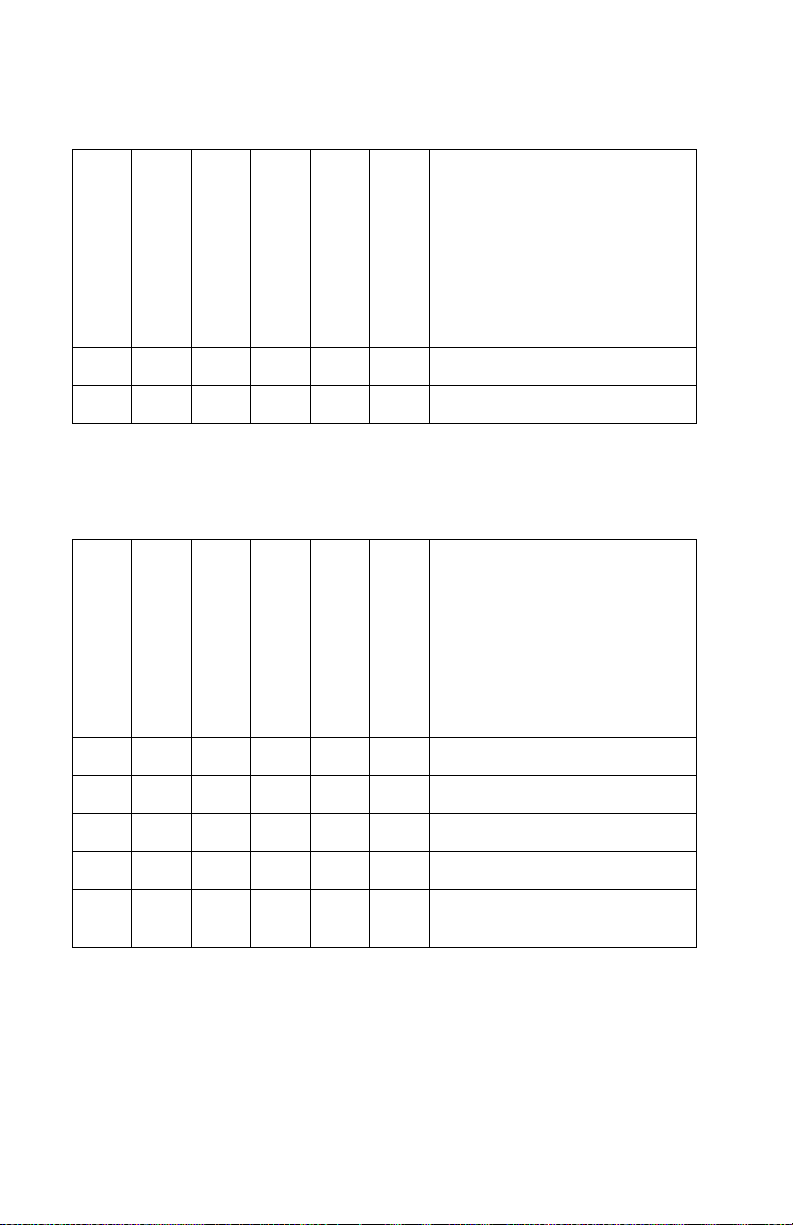
Obtaining information about printer service error codes
All lights flashing simultaneously designates a printer service error
as a primary code. Double press Continue to see the secondary
codes; double press Continue again to see the tertiary codes;
double press Continue the third time to return to the primary code.
All secondary codes have a flashing Ready/Data light but not the
Toner Low light. All tertiary codes have a flashing Toner Low light but
not a Ready/Data light.
All lights flashing simultaneously, as a result of sending data to the
printer, may indicate a code problem. Call Lexmark Customer
Support Center at 1–800–539–6275 for assistance.
2-44 Service Manual
Page 75

4500–E220/E321/E323
Service error codes
Service error codes are generally non–recoverable except in an
intermittent condition when you can power–on reset (POR) the
printer to temporarily recover from the error condition.
Controller software error / illegal trap
Contact the next level of support or call Lexmark 1–800–539–6275
for assistance.
(900)
Diagnostic information 2-45
Page 76
4500–E220/E321/E323
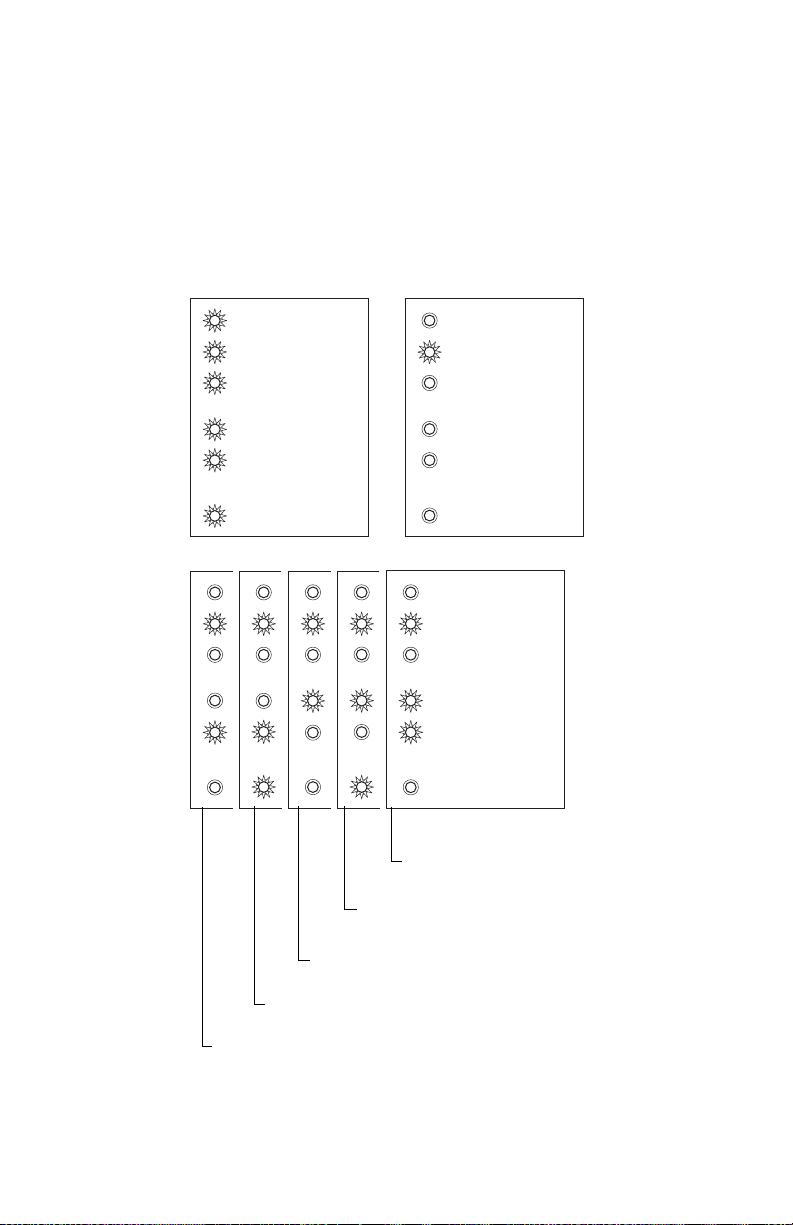
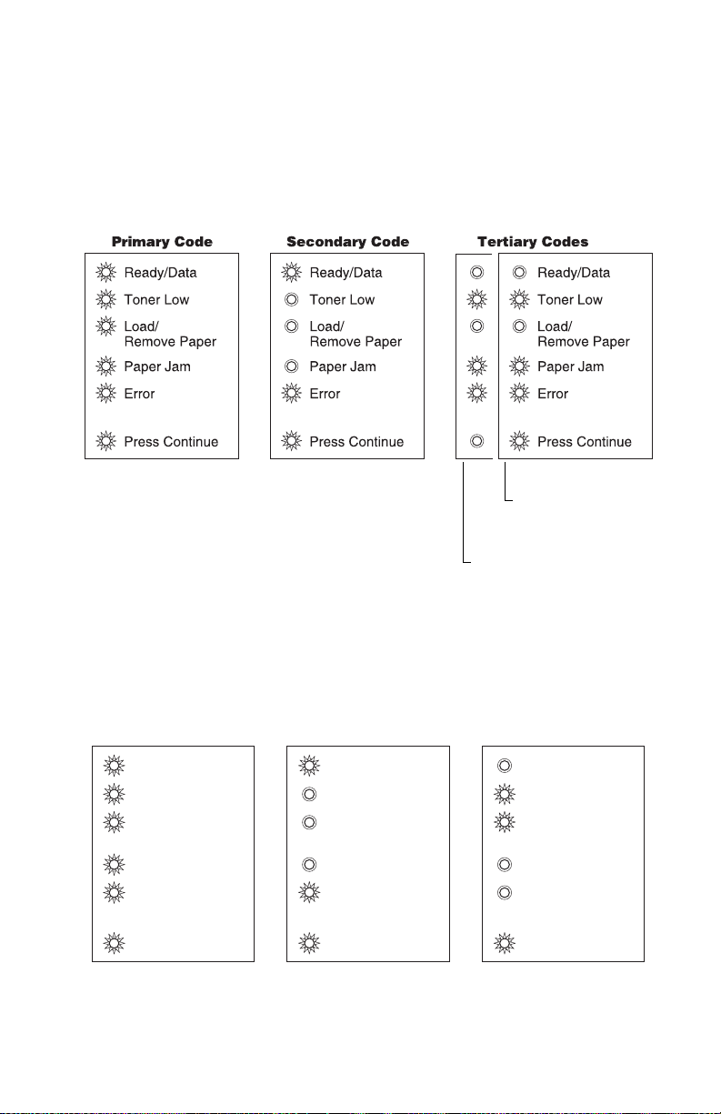
Engine flash or engine software errors
The first error message below (901) indicates the flash into which
the engine code is programmed is bad. Either the flash cannot be
erased or the program failed when programming was attempted.
The remaining errors, 902 through 906, indicate an unrecoverable
engine software error. Replace the controller card.
Primary Code Secondary Code
Ready/Data
Toner Low
Load/
Remove Paper
Paper Jam
Error
Press Continue
Tertiary Codes
Ready/Data
Toner Low
Load/
Remove Paper
Paper Jam
Error
Press Continue
Ready/Data
Toner Low
Load/
Remove Paper
Paper Jam
Error
Press Continue
RIP interface driver error (906).
General engine software error (902).
2-46 Service Manual
Interface violation by paper port
device (905).
Interface violation by RIP (904).
Paper port link drive error (903).
Page 77

4500–E220/E321/E323
Transfer roll error
Indicates a problem in the transfer roll area. Check the cable from
the HVPS (CN1) to the controller card (J3). Also, check voltage at
pin #4 of J3.
(917)
Diagnostic information 2-47
Page 78

4500–E220/E321/E323
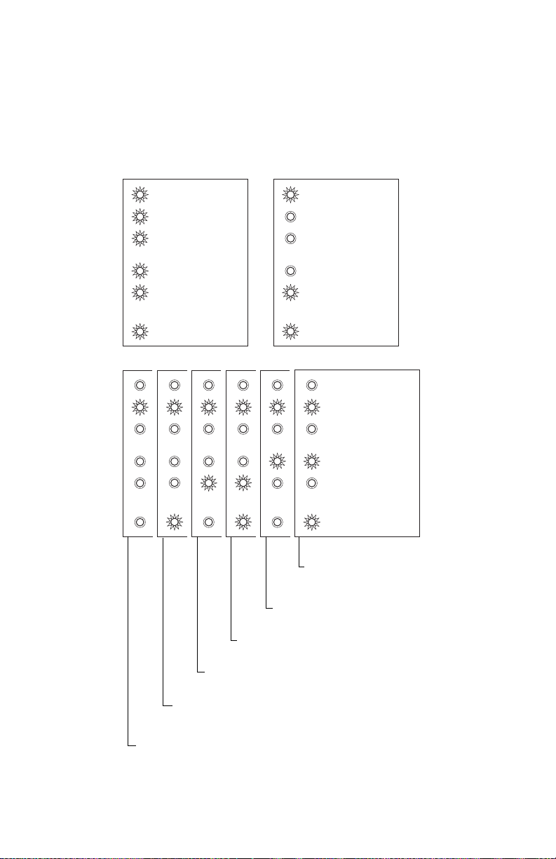
Fuser error
Indicates a problem with the fuser. See the “Fuser service check ”
on page 2-74 for more information.
Fuser below standby temperature at idle (921).
Fuser below temperature when printing (920).
2-48 Service Manual
Incorrect fuser lamp installed (925).
Open circuit in thermistor path (924).
Fuser too hot during printing or idle (923).
Fuser failed to reach standby temperature (922).
Page 79

4500–E220/E321/E323
Fan stalled
Indicates a printer fan stall.
Primary Code Secondary Code Tertiary Codes
Ready/Data
Toner Low
Load/
Remove Paper
Paper Jam
Error
Press Continue
Ready/Data
Toner Low
Load/
Remove Paper
Paper Jam
Error
Press Continue
Ready/Data
Toner Low
Load/
Remove Paper
Paper Jam
Error
Press Continue
(927)
Toner sensor error
Indicates a problem with either the toner sensor or print cartridge.
(929)
Either the printer’s toner sensor is faulty or the print cartridge is
defective.
Diagnostic information 2-49
Page 80
4500–E220/E321/E323
Printhead error
Indicates a problem with the printhead. Check cables to the
printhead. Replace the printhead as necessary. See “Printhead
assembly ” on page 4-2 for realignment procedures.
Primary Code Secondary Code
Ready/Data
Toner Low
Load/
Remove Paper
Paper Jam
Error
Press Continue
Tertiary Codes
Ready/Data
Toner Low
Load/
Remove Paper
Paper Jam
Error
Press Continue
Ready/Data
Toner Low
Load/
Remove Paper
Paper Jam
Error
Press Continue
Mirror motor not at operating
speed (935). (Verify +24 V dc
on pin #5 of J7.) (935)
Printhead–wrong printhead installed (930).
2-50 Service Manual
Mirror motor lost lock (934).
Mirror motor locked, no hsync received
(933).
Printhead–lost hsync (932).
Printhead–no first hsync (931).
(Verify interlock switch is plugged in at J6.)
Page 81
4500–E220/E321/E323
Transport motor error
Indicates a problem with the main drive motor system. The problem
could be the motor, the controller card, the cabling, or the drive
assembly. Check the cable connectors. The tertiary code below, with
four flashing lights indicates a problem in the drive assembly.
Transport motor
lost lock (937).
Transport motor initial
lock failure (936).
RIP to engine communication failure (controller card)
Indicates that the RIP processor cannot communicate with the
engine processor.
Primary Code Secondary Code Tertiary Codes
Ready/Data
Toner Low
Load/
Remove Paper
Paper Jam
Error
Press Continue
Ready/Data
Toner Low
Load/
Remove Paper
Paper Jam
Error
Press Continue
Ready/Data
Toner Low
Load/
Remove Paper
Paper Jam
Error
Press Continue
(939)
Diagnostic information 2-51
Page 82

4500–E220/E321/E323
RIP to engine communication failure (controller card)
Indicates a failure in the zero crossing signal which is used for fuser
control. It may indicate the wrong LVPS has been installed.
Primary Code Secondary Code Tertiary Codes
Ready/Data
Toner Low
Load/
Remove Paper
Paper Jam
Error
Press Continue
Ready/Data
Toner Low
Load/
Remove Paper
Paper Jam
Error
Press Continue
Ready/Data
Toner Low
Load/
Remove Paper
Paper Jam
Error
Press Continue
(940)
2-52 Service Manual
Page 83
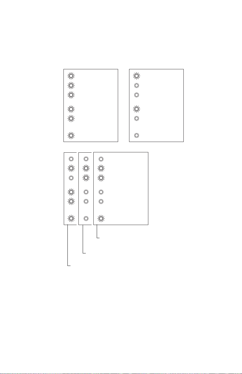
4500–E220/E321/E323
Engine circuitry failure (controller card)
Indicates a failure in the engine circuitry portion of the controller
card.
Primary Code Secondary Code
Ready/Data
Toner Low
Load/
Remove Paper
Paper Jam
Error
Press Continue
Tertiary Codes
Delay line calibration failure (949).
Ready/Data
Toner Low
Load/
Remove Paper
Paper Jam
Error
Press Continue
Ready/Data
Toner Low
Load/
Remove Paper
Paper Jam
Error
Press Continue
Pel clock check failure (948).
(947)
• PQET RAM test incomplete.
• PQET RAM test did not complete.
• PQET RAM test failed MARCH0.
• PQET RAM test failed MARCH1.
• PQET RAM test busy failure.
Diagnostic information 2-53
Page 84

4500–E220/E321/E323
NVRAM failure
Indicates a problem in the NVRAM. Replace the operator panel
assembly.
Primary Code Secondary Code
Ready/Data
Toner Low
Load/
Remove Paper
Paper Jam
Error
Press Continue
Tertiary Codes
NVRAM chip failure (952).
Ready/Data
Toner Low
Load/
Remove Paper
Paper Jam
Error
Press Continue
Ready/Data
Toner Low
Load/
Remove Paper
Paper Jam
Error
Press Continue
NVRAM CRC failure (954).
RIP firmware cannot communicate with
secure NVRAM (951).
NVRAM data does not match secure NVRAM (950).
Note: NVRAM is on the operator panel printed circuit board (PCB)
while secure NVRAM is on the controller PCB. Check margin
alignments after replacing the operator panel assembly. See
“Printhead assembly ” on page 4-2 (steps 1 through 11) for
more information. If margin errors are unacceptable,
corrections can only be made through software. Contact the
next level of support or Lexmark at 1–800–539–6275.
2-54 Service Manual
Page 85

4500–E220/E321/E323
Controller card error (ROM / NAND)
Indicates a failed controller card assembly. Replace the controller
card.
SRAM failure (959).
NAND failure (958).
ASIC failure (957).
Processor failure (956).
Code ROM or NAND failed cyclic redundancy check (CRC)
(955).
Diagnostic information 2-55
Page 86

4500–E220/E321/E323
RAM memory error
This error indicates RAM failure. Remove DIMM(s) and re–POR the
printer. If the error persists, replace the card. If the error subsides,
check each DIMM independently. Replace faulty DIMM.
RAM soldered on the board is bad (960).
2-56 Service Manual
(963).
RAM in slot 2 is bad (962).
RAM in slot 1 is bad (961).
Page 87

4500–E220/E321/E323
Network error
Indicates an error in the network circuitry. Replace the controller
card assembly.
Primary Code Secondary Code
Ready/Data
Toner Low
Load/
Remove Paper
Paper Jam
Error
Press Continue
Tertiary Codes
(973)
Ready/Data
Toner Low
Load/
Remove Paper
Paper Jam
Error
Press Continue
Ready/Data
Toner Low
Load/
Remove Paper
Paper Jam
Error
Press Continue
Flash parts failed
while programming
port (979).
(974)
Bad checksum while
programming port (978).
(970)
(971)
(972)
Unrecoverable software error in
network port (975).
Unrecognizable network port (975).
Diagnostic information 2-57
Page 88

4500–E220/E321/E323
Paper port communication failure
Indicates an error communicating with Tray 2, if installed. Remove
Tray 2 and recheck. If the error doesn’t recur, replace Tray 2. If the
error recurs, replace the controller card assembly.
Engine experiencing unreliable communications to
specified device (980).
2-58 Service Manual
Invalid command parameter
received by specified device
(984).
Invalid command received by
specified device (983).
Communications error detected by
specified device (982).
Engine protocol violation detected by the
specified device (981).
Page 89

4500–E220/E321/E323
Power–on operations
To access the printer operations for the E220, E321, E323:
1. Turn off the printer.
2. Press and hold the buttons in the following table for the
operation needed.
3. Turn on the printer. Hold the buttons until the lights cycle on the
operator panel.
4. Print menus by closing the top cover and then pressing
Continue until the lights flash (see samples on page 3-38 and
page 3-39).
Operation Power–on action
Enter configuration
menu mode
Print the print quality
test pages
Enter diagnostics
mode
Print the print quality
test pages
Reset NVRAM and
enter normal mode
1. Power on with top cover open and Continue
pressed.
2. Close cover once the Error light is displayed.
In configuration mode, press and release Cancel
until the top two lights come on. Press and hold
Continue until lights flash. See the note in item 3
page 3-40 for more information (Cartridge Lockout
function enabled).
1. Power on with top cover open and Cancel
pressed.
2. Close cover once the Error light is displayed.
In diagnostic mode, press and release Cancel
until the top two lights come on. Press and hold
Continue until lights are on. Press and hold
Continue until lights flash. See the note in item 3
page 3-40 for more information. (Cartridge
Lockout function disabled)
1. Power on with top cover open and both
Continue and Cancel buttons pressed.
2. Close cover once the Error light is displayed.
Diagnostic information 2-59
Page 90

4500–E220/E321/E323
Power–On Self Test (POST)
When you turn the printer on, it performs a power–on self test.
Check for correct POST functioning of the base printer by observing
the following symptoms:
Symptom tables
POST symptom table
Symptom Action
The main motor, cooling fan,
and fuser do not come on.
POST completes except one or
more lights do not come on.
None of the lights come on. See the “Operator panel service
Main motor does not come on. See the “Main motor service check ”
Fan does not come on. See the “Cooling fan service check
Fuser lamp does not come on. See the “Cold fuser service check ”
Fuser lamp never turns off. See the “Hot fuser service check ”
The paper feed picks and tries
to feed paper.
See the “Cover interlock switch
service check (E220/E321/E323) ” on
page 2-70.
See the “Operator panel service
check ” on page 2-79.
check ” on page 2-79.
on page 2-77.
(E220/E321/E323) ” on page 2-66.
on page 2-64.
on page 2-76.
See the “Paper feed service checks ”
on page 2-81.
2-60 Service Manual
Page 91

Printer Symptom Table
Symptom Action
4500–E220/E321/E323
Dead machine (no power) See “Dead machine service check ”
Fan noisy or not working See “Cooling fan service check
Fuser parts melted See “Hot fuser service check ” on
Fuser lamp doesn’t light See “Cold fuser service check ” on
Toner not fused to the paper See “Cold fuser service check ” on
Paper jams See “Paper feed service checks ” on
Main motor noisy or not moving See “Main motor service check ” on
Paper skew See the Note regarding alignment on
Printer not communicating with
host
on page 2-71.
(E320/E322) ” on page 2-65 or
“Cooling fan service check (E220/
E321/E323) ” on page 2-66.
page 2-76.
page 2-64.
page 2-64.
page 2-81.
page 2-77.
page 4-2 or “Paper feed service
checks ” on page 2-81.
See “Parallel port service check ” on
page 2-85.
Top cover will not close See “Cover interlock switch service
check (E320/E322) ” on page 2-69 or
“Cover interlock switch service
check (E220/E321/E323) ” on
page 2-70.
Operator panel button not
responding
Operator panel lights do not
light or are very dim
Blank page See “Blank page ” on page 2-86.
Black page See “Black page ” on page 2-87.
See “Operator panel service check ”
on page 2-79 or “Controller card
service check (E220/E321/E323) ” on
page 2-67.
See “Controller card service check
(E220/E321/E323) ” on page 2-67.
Diagnostic information 2-61
Page 92

4500–E220/E321/E323
Symptom Action
Heavy background See “Heavy background ” on
page 2-88.
Light print See “Light print ” on page 2-90.
White or black lines or bands See “White or black lines or bands ”
on page 2-91.
Toner on back of page See “Toner on back of page ” on
Paper never picks See “Paper never picks ” on
Paper feeds continuously See “Paper picks during POST and/or
Paper wrinkled or bent See “Paper “trees,” wrinkles, stacks
page 2-91.
page 2-83.
continuously ” on page 2-81.
poorly or curls ” on page 2-84.
2-62 Service Manual
Page 93

Service checks
Service checks which involve measuring voltages of the
LVPS/engine boards must be performed with the printer
positioned on its back side. This provides the servicer
access to the circuit boards underneath the printer
while supplying necessary power to the rest of the
printer.
4500
Diagnostic information 2-63
Page 94

4500
Cold fuser service check
Make sure the correct voltage lamp is installed. The voltage rating is
stamped on one of the lamp contacts.
FRU Action
Fuser lamp
Lamp cable
LVPS
Fuser
If the fuser lamp comes on and a
fuser failure light error code displays,
be sure the thermistor is contacting
the hot roll and the thermistor cable
is firmly seated in connector J7 on
the engine board (E320/E322) or
J14 on controller card
(E220/E321/E323).
Check for excessive toner buildup on
the surface of the thermistor. Clean
as necessary.
With the printer unplugged,
disconnect the thermistor cable from
J7 (engine board in E320/E322) or
J14 (controller card in
E220/E321/E323).
Measure the resistance of the
thermistor. The resistance measures
approximately 1K ohms immediately
after printing or POR to
approximately 240K ohms when
thermistor reaches room
temperature. (It may take 30 minutes
to cool.)
Replace the fuser assembly as
necessary.
2-64 Service Manual
Page 95

Cooling fan service check (E320/E322)
FRU Action
Cooling fan Make sure the cooling fan motor
cable plug is properly seated on the
engine board.
Unplug the printer and disconnect
the cooling fan cable on the engine
board.
Restore printer power. Within
approximately 3 seconds the engine
board should apply +24 Volts direct
current (V dc) to the fan. See
“Connector locations ” on
page 5-1 for more information.
• If voltage is present, replace the
cooling fan.
• If voltage is not present, see the
“Engine board service check
(E320/E322) ” on page 2-72 for
more information.
4500
Service checks involve measuring voltages of the LVPS,
high voltage power supply (HVPS), and controller card
assembly. Continuity and resistance verifications are
done on cables and components as required.
Note: When looking at the printed side of a PCB, connectors are
designated with “J” followed by a number. Pin 1 is designated
on the PCB by an adjacent “1” or triangle. Pin numbers index
sequentially to the opposite end of the connector. See “RIP
controller (E220/E321/E323 only) ” on page 5-8 for more
information.
Diagnostic information 2-65
Page 96

4500
Cooling fan service check (E220/E321/E323)
FRU Action
Cooling fan Make sure the cooling fan motor
cable plug is properly seated.
Turn the printer off and disconnect
the cooling fan cable at J2 on the
controller card.
Turn the printer on. Within a few
seconds the controller card
assembly should apply +24 V dc to
pin #1. See “RIP controller (E220/
E321/E323 only) ” on page 5-8 for
more information.
• If voltage is present, replace the
cooling fan first. If the fan still
doesn’t function, replace the
controller card.
Note: The fan speed is controlled by
a module on the PCB.
Therefore, +24 V dc is
constantly supplied at pin #1
(J2). Pin #2, the return,
typically indicates varying
voltages of less than
+10 V dc in operation.
• If voltage is not present, see the
“RIP controller (E220/E321/
E323 only) ” on page 5-8 for
more information.
2-66 Service Manual
Page 97

Controller card service check (E220/E321/E323)
FRU Action
Controller card assembly Verify +5 V dc and +24 V dc inputs
from the LVPS.
• Turn the printer off.
• Disconnect the LVPS cable from
the controller card at J1. See
“Controller (E220/E321/E323
only) ” on page 5-7 for more
information.
• Turn the printer on.
Verify +24 V dc from the cable,
pins 3 and 4. Verify +5 V dc on cable
pin 1.
Verify that pins 2, 5 and 6 on both
the cable and the card connectors
are grounded.
• If voltages are correct, check the
continuity in the cable. If the
cable is good, see the “Low
voltage power supply (LVPS)
service check ” on page 2-76
for more information.
• If grounds are not correct on the
cable, first check it for continuity
and then the LVPS.
• If the grounds are not correct on
the controller card, replace the
controller card. (Check with one
probe on the connector pin and
the other on the cards ground
plane found at each screw
head.)
4500
Diagnostic information 2-67
Page 98

4500
FRU Action
Controller card assembly
(continued)
Note: With all cables connected, the
printer should complete
POST within approximately
12–15 seconds in the
following sequence:
1. All operator panel lights on solid
momentarily.
2. Lights then flash on and off
sequentially.
After lights quit flashing, the
Ready/Data light turns on solid.
3. The cooling fan comes on.
4. The fuser lamp comes on.
5. The drive motor runs.
6. The printhead motor runs.
7. The printer cycles down into
standby mode/ready.
If immediately following power–on
the operator panel lights are active
but the printer does not go through
steps 1 and 2 above, replace the
controller card assembly.
Note: U.S. versus non–U.S. and the
printer configuration ID can
be reset. See “Printer
diagnostics mode ” on
page 3-40 for more
information.
If some lights are on or flashing,
see “Status information light
patterns ” on page 2-38 to
determine a course of action.
2-68 Service Manual
Page 99

Cover interlock switch service check (E320/E322)
Note: Make sure a toner cartridge is installed and the cover closes
all the way, engaging the cover open switch lever.
FRU Action
4500
Cover interlock switch Disconnect the cover interlock cable
plug from the engine board.
Push the cover interlock switch to
the closed position and check for
continuity. See “Connector
locations ” on page 5-1 for more
information.
If the switch does not close, replace
the switch.
Check for +24 V dc. If voltage is not
present, see “Engine board
service check (E320/E322) ” on
page 2-72 for more information.
Diagnostic information 2-69
Page 100

4500
Cover interlock switch service check (E220/E321/E323)
Note: Make sure a toner cartridge is installed and the cover closes
all the way, engaging the cover open switch lever.
FRU Action
Cover interlock switch Disconnect the cover interlock cable
from the controller card at J6.
Verify continuity between cable
pin 1 and pin 2 with the door closed.
Verify continuity between cable
pin 1 and pin 3 with the door open.
• If either fail continuity, replace the
cover interlock switch.
• If both pass continuity, turn the
printer on and verify +5 V dc on
pin 2 at J6 on the card.
• Verify pins1 and 3 are ground.
• If voltage or ground is not present,
see “Controller card service
check (E220/E321/E323) ” on
page 2-67 for more information.
Verify discontinuity between pins 2
and 3 whether the door is open or
closed.
Replace the cover interlock switch if
faulty.
2-70 Service Manual
 Loading...