

Page 1

Optra
TM
• Table of Contents
• Start Diagnostics
• Safety and Notices
• Trademarks
E310/E312
4044-XXX
•Index
Lexmark and Lexmark with diamond
design are trademarks of Lexmark
International, Inc., registered in the
United States and/or other countries.
Page 2

4044-XXX
Edition: July 2000
The following paragraph does not apply to any country where such provisions are
inconsiste nt with local law: LEXMARK INTERNATIONAL, INC. PROV IDES THIS
PUBLICATION “AS IS” WITHOUT WARRANTY OF ANY KIND, EITHER EXPRE SS OR
IMPLIED , INCLUDING, BUT NOT LIMITED TO, THE IMPLIED WARRANTIES OF
MERCHANT ABILITY OR FITNESS FOR A PARTICULAR PURPOSE. Some states do not
allow disclaimer of express or implied warranties in certain transactions; therefore, this
statement may not apply to you.
This publication could include technical inaccuracies or typographical errors. Changes are
periodically made to the information herein; these changes will be incorporated in later
editions. Improvements or changes in the products or the programs described may be
made at any time.
A form for reader’s comments is provided at the back of this publication. If the form has
been removed, comments may be addressed to Lexmark International, Inc., Department
D22A/032-2, 740 West New Circle Road, Lexington, Kentucky 40550, U.S.A. Lexmark
may use or distribute any of the information you supply in any way it believes appropriate
without incurring any obligation to you. You can purchase additional copies of publications
related to this product by calling 1-800-553-9727. In other countries, contact your point of
purchase.
Lexmark and Optra are trademarks of Lexmark International, Inc., registered in the United
States and/or other countries.
Other trademarks are the property of their respective owners.
© Copyright Lexmark International, Inc. 2000.
All rights reserved.
UNITED STA TES GOVERNMENT RESTRICTED RIGHTS
This software and documentation are provided with RESTRICTED RIGHTS. Use,
duplication or disclosure by the Government is subject to restrictions as set forth in
subparagraph (c)(1)(ii) of the Rights in Technical Data and Computer Software clause at
DF ARS 252.227-7013 and in applicable FAR provisions: Lexmark International, Inc.,
Lexington, KY 40550.
Page 3

4044-XXX
Table of Contents
Notices and Safety Information . . . . . . . . . . . . . . . . . . . . . . . . . . . . .v
Laser Notice . . . . . . . . . . . . . . . . . . . . . . . . . . . . . . . . . . . . . . . . . . . . .v
Safety Information . . . . . . . . . . . . . . . . . . . . . . . . . . . . . . . . . . . . . . .xv
General Information . . . . . . . . . . . . . . . . . . . . . . . . . . . . . . . . . . . . 1-1
Options . . . . . . . . . . . . . . . . . . . . . . . . . . . . . . . . . . . . . . . . . . . . . . . 1-1
Diagnostic Information . . . . . . . . . . . . . . . . . . . . . . . . . . . . . . . . . 2-1
Start . . . . . . . . . . . . . . . . . . . . . . . . . . . . . . . . . . . . . . . . . . . . . . . . . 2-1
Service Error Codes. . . . . . . . . . . . . . . . . . . . . . . . . . . . . . . . . . . 2-2
User Error Message Table . . . . . . . . . . . . . . . . . . . . . . . . . . . . . . 2-6
Power-On Self Test (POST ). . . . . . . . . . . . . . . . . . . . . . . . . . . . . 2-9
Symptom Tables . . . . . . . . . . . . . . . . . . . . . . . . . . . . . . . . . . . . 2-10
Service Checks . . . . . . . . . . . . . . . . . . . . . . . . . . . . . . . . . . . . . . . 2-12
Cooling Fan Service Check . . . . . . . . . . . . . . . . . . . . . . . . . . . . 2-12
Cover Open Switch Service Check . . . . . . . . . . . . . . . . . . . . . . 2-13
Dead Machine Service Check . . . . . . . . . . . . . . . . . . . . . . . . . . 2-14
Fuser Service Check . . . . . . . . . . . . . . . . . . . . . . . . . . . . . . . . . 2-17
Main Motor Service Check. . . . . . . . . . . . . . . . . . . . . . . . . . . . . 2-21
Operator Panel Service Check. . . . . . . . . . . . . . . . . . . . . . . . . . 2-23
Operator Panel Button Service Check . . . . . . . . . . . . . . . . . . . . 2-24
Paper Feed Service Check . . . . . . . . . . . . . . . . . . . . . . . . . . . . 2-24
Print Quality Service Check . . . . . . . . . . . . . . . . . . . . . . . . . . . . 2-28
Parallel Port Service Check . . . . . . . . . . . . . . . . . . . . . . . . . . . . 2-35
Diagnostic Aids . . . . . . . . . . . . . . . . . . . . . . . . . . . . . . . . . . . . . . . 3-1
Memory Test . . . . . . . . . . . . . . . . . . . . . . . . . . . . . . . . . . . . . . . . 3-1
Diagnostic Test . . . . . . . . . . . . . . . . . . . . . . . . . . . . . . . . . . . . . . 3-1
Print Quality Test . . . . . . . . . . . . . . . . . . . . . . . . . . . . . . . . . . . . . 3-2
User Mode Print Test . . . . . . . . . . . . . . . . . . . . . . . . . . . . . . . . . . 3-3
Configuration Mode . . . . . . . . . . . . . . . . . . . . . . . . . . . . . . . . . . . 3-3
Hex Trace. . . . . . . . . . . . . . . . . . . . . . . . . . . . . . . . . . . . . . . . . . 3-11
Restoring Factory Defau lts. . . . . . . . . . . . . . . . . . . . . . . . . . . . . 3-12
Engine Clean Cycle . . . . . . . . . . . . . . . . . . . . . . . . . . . . . . . . . . 3-13
Toggle Demo/Normal Mode. . . . . . . . . . . . . . . . . . . . . . . . . . . . 3-14
Printer Operation . . . . . . . . . . . . . . . . . . . . . . . . . . . . . . . . . . . . 3-14
Paper Path . . . . . . . . . . . . . . . . . . . . . . . . . . . . . . . . . . . . . . . . . 3-15
Repair Information . . . . . . . . . . . . . . . . . . . . . . . . . . . . . . . . . . . . . 4-1
Handling ESD-Sensitive Parts . . . . . . . . . . . . . . . . . . . . . . . . . . . . . 4-1
iii
Page 4

4044-XXX
Removal Procedures . . . . . . . . . . . . . . . . . . . . . . . . . . . . . . . . . . . . .4-2
Screw Identification Table . . . . . . . . . . . . . . . . . . . . . . . . . . . . . . .4-2
Covers. . . . . . . . . . . . . . . . . . . . . . . . . . . . . . . . . . . . . . . . . . . . . .4-2
Frame Assembly. . . . . . . . . . . . . . . . . . . . . . . . . . . . . . . . . . . . . .4-7
Fuser Assembly. . . . . . . . . . . . . . . . . . . . . . . . . . . . . . . . . . . . . . .4-8
HVPS. . . . . . . . . . . . . . . . . . . . . . . . . . . . . . . . . . . . . . . . . . . . . .4-10
Interconnect Board (model E310) . . . . . . . . . . . . . . . . . . . . . . . .4-12
Engine/LVPS Board (model E310) . . . . . . . . . . . . . . . . . . . . . . .4-13
Engine/LVPS Board (model E312) . . . . . . . . . . . . . . . . . . . . . . .4-15
Main Drive Assembly. . . . . . . . . . . . . . . . . . . . . . . . . . . . . . . . . .4-17
Pick Roll Assembly . . . . . . . . . . . . . . . . . . . . . . . . . . . . . . . . . . .4-18
Printhead Assembly . . . . . . . . . . . . . . . . . . . . . . . . . . . . . . . . . .4-20
Transfer Roll . . . . . . . . . . . . . . . . . . . . . . . . . . . . . . . . . . . . . . . .4-21
Connector Locations . . . . . . . . . . . . . . . . . . . . . . . . . . . . . . . . . . . .5-1
Controller Board (model E310/E312) . . . . . . . . . . . . . . . . . . . . . .5-1
Engine/LVPS Board (model E310) . . . . . . . . . . . . . . . . . . . . . . . .5-4
Engine Board (model E312) . . . . . . . . . . . . . . . . . . . . . . . . . . . . .5-9
LVPS (model E312). . . . . . . . . . . . . . . . . . . . . . . . . . . . . . . . . . .5-14
High Voltage Power Supply (model E310) . . . . . . . . . . . . . . . . .5-16
High Voltage Power Supply (model E312) . . . . . . . . . . . . . . . . .5-18
Interconnect Board (model E310) . . . . . . . . . . . . . . . . . . . . . . . .5-21
Parts Catalog . . . . . . . . . . . . . . . . . . . . . . . . . . . . . . . . . . . . . . . . . .6-1
Assembly 1: Covers . . . . . . . . . . . . . . . . . . . . . . . . . . . . . . . . . . .6-2
Assembly 2: Frame . . . . . . . . . . . . . . . . . . . . . . . . . . . . . . . . . . . .6-6
Assembly 3: Fuser. . . . . . . . . . . . . . . . . . . . . . . . . . . . . . . . . . . .6-10
Assembly 4: Main Drive. . . . . . . . . . . . . . . . . . . . . . . . . . . . . . . .6-14
Assembly 5: Paper Feed. . . . . . . . . . . . . . . . . . . . . . . . . . . . . . .6-16
Assembly 6: Electronics (model E310) . . . . . . . . . . . . . . . . . . . .6-20
Assembly 6: Electronics (model E312) . . . . . . . . . . . . . . . . . . . .6-24
Assembly 7: Options . . . . . . . . . . . . . . . . . . . . . . . . . . . . . . . . . .6-26
Assembly 8: Miscellaneous. . . . . . . . . . . . . . . . . . . . . . . . . . . . .6-27
Index . . . . . . . . . . . . . . . . . . . . . . . . . . . . . . . . . . . . . . . . . . . . . . . . . I-1
iv Service Manual
Page 5

4044-XXX
Notices and Safety Information
Laser Notice
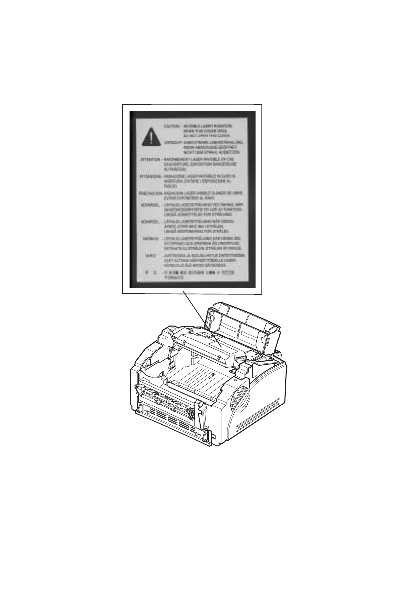
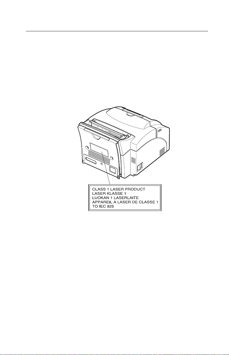
The printer is certified in the U.S. to conform to the requirements of
DHHS 21 CFR Subchapter J for Class I (1) laser products, and
elsewhere is certified as a Class I laser product conforming to the
requirements of IEC 825.
Class I laser products are not considered to be hazardous. The
printer contains internally a Class IIIb (3b) laser that is nominally a 5
milliwatt gallium arsenide laser operating in the wavelength region of
770-795 nanometers. The laser system and printer are designed so
there is never any human access to laser radiation above a Class I
level during normal operation, user maintenance, or prescribed
service condition.
v
Page 6
4044-XXX
Laser Advisory Label
vi
Page 7
4044-XXX
Class 1 Laser Statement Label
vii
Page 8

4044-XXX
Laser
Der Drucker erfüllt gemäß amtlicher Bestätigung der USA die
Anforderungen der Bestimmung DHHS (Department of Health and
Human Services) 21 CFR Teil J für Laserprodukte der Klasse I (1).
In anderen Ländern gilt der Drucker als Laserprodukt der Klasse I,
der die Anforderungen der IEC (International Electrotechnical
Commission) 825 gemäß amtlicher Bestätigung erfüllt.
Laserprodukte der Klasse I gelten als unschädlich. Im Inneren des
Druckers befindet sich ein Laser der Klasse IIIb (3b), bei dem es
sich um einen Galliumarsenlaser mit 5 Milliwatt handelt, der Wellen
der Länge 770-795 Nanometer ausstrahlt. Das Lasersystem und der
Drucker sind so konzipiert, daß im Normalbe tr ie b, bei der Wartung
durch den Benutzer oder bei ordnungsgemäßer Wartung durch den
Kundendienst Laserbestrahlung, die die Klasse I übersteigen würde,
Menschen keinesfalls erreicht.
Avis relatif à l’utilisation de laser
Pour les Etats-Unis : cette imprimante est certifiée conforme aux
provisions DHHS 21 CFR alinéa J concernant les produits laser de
Classe I (1). Pour les autres pays : cette imprimante répond aux
normes IEC 825 relatives aux produits laser de Classe I.
Les produits laser de Classe I sont considérés comme des produits
non dangereux. Cette imprimante est équipée d’un laser de Classe
IIIb (3b) (arséniure de gallium d’une puissance nominale de 5
milliwatts) émettant sur des longueurs d’onde comprises entre 770
et 795 nanomètres. L’imprimante et son système laser sont conçus
pour impossible, dans des conditions normales d’utilisation,
d’entretien par l’utilisateur ou de révision, l’exposition à des
rayonnements laser supérieurs à des ra yonnements de Classe I .
viii
Page 9

4044-XXX
Avvertenze sui prodotti laser
Questa stampante è certificata negli Stati Uniti per essere conforme
ai requisiti del DHHS 21 CFR Sottocapitolo J per i prodotti laser di
classe 1 ed è certificata negli altri Paesi come prodotto laser di
classe 1 conforme ai requisiti della norma CEI 825.
I prodotti laser di classe non sono considerati pericolosi. La
stampante contiene al suo interno un laser di classe IIIb (3b)
all’arseniuro di gallio della potenza di 5mW che opera sulla
lunghezza d’onda compresa tra 770 e 795 nanometri. Il sistema
laser e la stampante sono stati progettati in modo tale che le
persone a contatto con la stampante, durante il normale
funzionamento, le operazioni di servizio o quelle di assistenza
tecnica, non ricevano radiazioni laser superiori al livello della classe
1..
Avisos sobre el láser
Se certifica que, en los EE.UU., esta impresora cumple los
requisitos para los productos láser de Clase I (1) establecidos en el
subcapítulo J de la norma CFR 21 del DHHS (Departamento de
Sanidad y Servicios) y, en los demás países, reúne todas las
condiciones expuestas en la norma IEC 825 para productos láser de
Clase I (1).
Los productos láser de Clase I no se consideran peligrosos. La
impresora contiene en su interior un láser de Clase IIIb (3b) de
arseniuro de galio de funcionamiento nominal a 5 milivatios en una
longitud de onda de 770 a 795 nanómetros. El sistema láser y la
impresora están diseñados de forma que ninguna persona pueda
verse afectada por ningún tipo de radiac ión láser superior al nivel de
la Clase I durante su uso normal, el mantenimiento realizado por el
usuario o cualquier otra situación de servicio técnico.
ix
Page 10

4044-XXX
Declaração sobre Laser
A impressora está certificada nos E.U.A. em conformidade com os
requisitos da regulamentação DHHS 21 CFR Subcapítulo J para a
Classe I (1) de produtos laser. Em outros locais, está certificada
como um produto laser da Classe I, em conformidade com os
requisitos da norma IEC 825.
Os produtos laser da Classe I não são considerados perigosos.
Internamente, a impressora contém um produto laser da Classe IIIb
(3b), designado laser de arseneto de potássio, de 5 milliwatts
,operando numa faixa de comprimento de onda entre 770 e 795
nanómetros. O sistema e a impressora laser foram concebidos de
forma a nunca existir qualquer possiblidade de acesso humano a
radiação laser superior a um nível de Classe I durante a operação
normal, a manutenção feita pelo utilizador ou condições de
assistência prescritas.
Laserinformatie
De printer voldoet aan de eisen die gesteld worden aan een
laserprodukt van klasse I. Voor de Verenigde Staten zijn deze eisen
vastgelegd in DHHS 21 CFR Subchapter J, voor andere landen in
IEC 825.
Laserprodukten van klasse I worden niet als ongevaarlijk
aangemerkt. De printer is voorzien van een laser van klasse IIIb
(3b), dat wil zeggen een gallium arsenide-laser van 5 milliwatt met
een golflengte van 770-795 nanometer. Het lasergedeelte en de
printer zijn zo ontworpen dat bij normaal gebruik, bij onderhoud of
reparatie conform de voorschriften, nooit blootstelling mogelijk is
aan laserstraling boven een niveau zoals voorgeschreven is voor
klasse 1.
x
Page 11

4044-XXX
Lasermeddelelse
Printeren er godkendt som et Klasse I-laserprodukt, i
overenstemmelse med kravene i IEC 825.
Klasse I-laserprodukter betragtes ikke som farlige. Printeren
indeholder internt en Klasse IIIB (3b)-laser, der nominelt er en 5
milliwatt galliumarsenid laser, som arbejder på bølgelængdeområdet
770-795 nanometer. Lasersystemet og printeren er udformet
således, at mennesker aldrig udsættes for en laserstråling over
Klasse I-niveau ved normal drift, brugervedligeholdelse eller
obligatoriske servi c ebet ing el se r.
Huomautus laserlaitteesta
Tämä kirjoitin on Yhdysvalloissa luokan I (1) laserlaitteiden DHHS
21 CFR Subchapter J -määrityksen mukainen ja muualla luokan I
laserlaitteiden IEC 825 -määrityksen mukainen.
Luokan I laserlaitteiden ei katsota olevan vaarallisia käyttäjälle.
Kirjoittimessa on sisäinen luokan IIIb (3b) 5 milliwatin
galliumarsenidilaser, joka toimii aaltoalueella 770 - 795 nanometriä.
Laserjärjestelmä ja kirjoitin on suunniteltu siten, että käyttäjä ei
altistu luokan I määrityksiä voimakkaammalle säteilylle kirjoittimen
normaalin toiminnan, käyttäjän tekemien huoltotoimien tai muiden
huoltotoimien yhteydessä.
VARO! Avattaessa ja suojalukitus ohitettaessa olet alttiina
näkymättömälle lasersäteilylle. Älä katso säteeseen.
VARNING! Osynlig laserstrålning när denna del är öppnad och
spärren är urkopplad. Betrakta ej strålen.
xi
Page 12

4044-XXX
Laser-notis
Denna skrivare är i USA certifierad att motsvara kraven i DHHS 21
CFR, underparagraf J för laserprodukter av Klass I (1). I andra
länder uppfyller skrivaren kraven för laserprodukter av Klass I enligt
kraven i IEC 825.
Laserprodukter i Klass I anses ej hälsovådliga. Skrivaren har en
inbyggd laser av Klass IIIb (3b) som består av en laserenhet av
gallium-arsenid på 5 milliwatt som arbetar i våglängdsområdet 770795 nanometer. Lasersystemet och skrivaren är utformade så att det
aldrig finns risk för att någon person utsätts för laserstrålning över
Klass I-nivå vid normal användning, underhåll som utförs av
användaren eller annan föreskriven serviceåtgärd.
Laser-melding
Skriveren er godkjent i USA etter kravene i DHHS 21 CFR,
underkapittel J, for klasse I (1) laserprodukter, og er i andre land
godkjent som et Klasse I-laserprodukt i samsvar med kravene i IEC
825.
Klasse I-laserprodukter er ikke å betrakte som farlige. Skriveren
inneholder internt en klasse IIIb (3b)-laser, som består av en
gallium-arsenlaserenhet som avgir stråling i bølgelengdeområdet
770-795 nanometer. Lasersystemet og skriveren er utformet slik at
personer aldri utsettes for laserstråling ut ov er klasse I-nivå under
vanlig bruk, vedlikehold som utføres av brukeren, eller foreskrevne
serviceoperasjoner.
xii
Page 13

4044-XXX
Avís sobre el Làser
Segons ha estat certificat als Estats Units, aquesta impressora
compleix els requisits de DHHS 21 CFR, apartat J, pels productes
làser de classe I (1), i segons ha estat certificat en altres llocs, és un
producte làser de classe I que compleix els requisits d’IEC 825.
Els productes làser de classe I no es consideren perillosos. Aquesta
impressora conté un làser de classe IIIb (3b) d’arseniür de gal.li,
nominalment de 5 mil.liwats, i funciona a la regió de longitud d’ona
de 770-795 nanòmet re s. El siste ma làser i la impressora han sigut
concebuts de manera que mai hi hagi exposició a la radiació làser
per sobre d’un nivell de classe I durant una operació normal, durant
les tasques de manteniment d’usuari ni durant els serveis que
satisfacin les condicions prescrites.
xiii
Page 14
4044-XXX
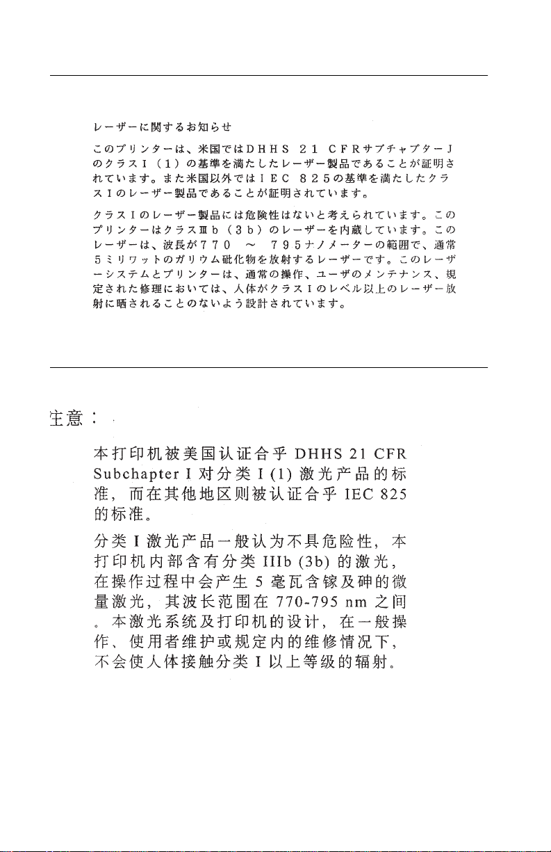
Japanese Laser Notice
Chinese Laser Notice
xiv
Page 15
4044-XXX
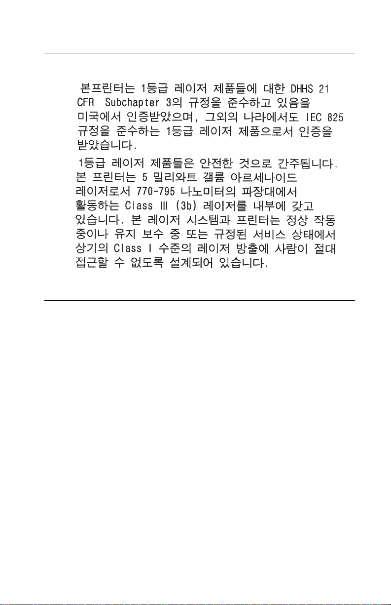
Kore an Laser Notice
Safety Inf ormation
• This product is designed, tested and approved to meet strict
global safety standards with the use of specific Lexmark
components. The safety features of some parts may not
always be obvious. Lexmark is not responsible for the use of
other replacement parts.
• The maintenance information for this product has been
prepared for use by a professional service person and is not
intended to be used by others.
• There may be an increased risk of electric shock and
personal injury during disassembly and servicing of this
product. Professional service personnel should understand
this and take necessary precautions.
xv
Page 16

4044-XXX
Consignes de Sécurité
• Ce produit a été conçu, testé et approuvé pour respecter les
normes strictes de sécurité globale lors de l'utilisation de
composants Lexmark spécifiques. Les caractéristiques de
sécurité de certains éléments ne sont pas toujours évidentes.
Lexmark ne peut être tenu responsable de l'utilisation
d'autres pièces de rechange.
• Les consignes d'entretien et de réparation de ce produit
s'adressent uniquement à un personnel de maintenance
qualifié.
• Le démontage et l'entretien de ce produit pouvant présenter
certai ns risques électriques, le personnel d'entretien qualifié
devra prendre toutes les précautions nécessaires.
Norme di sicurezza
• Il prodotto è stato progettato, testato e approvato in
conformità a severi standard di sicurezza e per l’utilizzo con
componenti Lexmark specifici. Le caratteristiche di sicurezza
di alcune parti non sempre sono di immediata comprensione.
Lexmark non è responsabile per l’utilizzo di parti di ricambio
di altri produttori.
xvi
• Le informazioni riguardanti la manutenzione di questo
prodotto sono indirizzate soltanto al personale di assistenza
autorizzato.
• Durante lo smontaggio e la manutenzione di questo prodotto,
il rischio di subire scosse elettriche e danni alla persona è più
elevato. Il personale di assistenza autorizzato, deve, quindi,
adottare le precauzioni necessarie.
Page 17

4044-XXX
Sicherheitshinweise
• Dieses Produkt und die zugehörigen Komponenten wurden
entworfen und getestet, um beim Einsatz die weltweit
gültigen Sicherheitsanforderungen zu erfüll en. Die
sicherheitsrelevanten Funktionen der Bauteile und Optionen
sind nicht immer offensichtlich. Sofern Teile eingesetzt
werden, die nicht von Lexmark sind, wird von Lexmark
keinerlei Verantwortung oder Haftung für dieses Produkt
übernommen.
• Die Wartungsinformationen für dieses Produkt sind
ausschließlich für die Verwendung durch einen
Wartungsfachmann bestimmt.
• Während des Auseinandernehmens und der Wartung des
Geräts besteht ein zusätzliches Risiko eines elektrischen
Schlags und körperlicher Verletzung. Das zuständige
Fachpersonal sollte entsprechende Vorsichtsmaßnahmen
treffen.
Pautas de Seguridad
• Este producto se ha diseñado, verificado y aprobado para
cumplir los más estrictos estándares de seguridad global
usando los componentes específicos de Lexmark. Puede
que las características de seguridad de algunas piezas no
sean siempre evidentes. Lexmark no se hace responsable
del uso de otras piezas de recambio.
• La información sobre el mantenimiento de este producto
está dirigida exclusivamente al personal cualificado de
mantenimiento.
• Existe mayor riesgo de descarga eléctrica y de daños
personales durante el desmontaje y la reparación de la
máquina. El personal cualificado debe ser consciente de este
peligro y tomar las precauciones necesarias.
xvii
Page 18

4044-XXX
Informações de Segurança
• Este produto foi concebido, testado e aprovado para
satisfazer os padrões globais de segurança na utilização de
componentes específicos da Lexmark. As funções de
segurança de alguns dos componentes podem não ser
sempre óbvias. A Lexmark não é responsável pela u til iz ação
de outros componentes de substituição.
• As informações de segurança relativas a este produto
destinam-se a profissionais destes serviços e não dev em ser
utilizadas por outras pessoas.
• Risco de choques eléctricos e ferimentos graves durante a
desmontagem e manutenção deste produto. Os profissionais
destes serviços devem estar avisados deste facto e tomar os
cuidados necessários.
Informació de Seguretat
• Aquest producte està dissenyat, comprovat i aprovat per tal
d'acomplir les estrictes normes de seguretat globals amb la
utililització de components específics de Lexmark. Les
característiques de seguretat d'algunes peces pot ser que no
sempre siguin òbvies. Lexmark no es responsabilitza de l'us
d'altres peces de recanvi.
xviii
• La informació pel manteniment d’aquest producte està
orientada exclusivament a professionals i no està destinada
a ningú que no ho sigui.
• El risc de xoc elèctric i de danys personals pot augmentar
durant el procés de desmuntatge i de servei d’aquest
producte. El personal professional ha d’estar-ne assabentat i
prendre les mesures convenients.
Page 19
4044-XXX
Chinese Safety Information
Korean Safety Information
xix
Page 20

4044-XXX
xx
Page 21

4044-XXX
1. General Information
This printer is a letter-quality laser page printer designed to attach to
an IBM Personal Computer or other computers compatible with the
IBM Personal Computer (with 386 processor or higher) and
Macintosh Computers via the USB connection.
Product
Name
MT/Model 4044-001 4044-201 4044-2L1 4044-2L2
Speed 8 pages
Base
Memory
Emulations PSLII,
Connectivity Parallel/
Resolution True 600dpi/Image Quality 1200dpi
Starter
Toner
Cartridge
Optra
E310
per minute
2MB 4MB 4MB 2MB
PCL6,
PPDS
USB
6k pages 6k pages 1.5k pages 1.5k pages
Optra
E312
10 pages
per minute
PSLII,
PCL6,
PPDS
Parallel/
USB
Optra
E312L
10 pages
per minute
PSLII,
PCL6,
PPDS
Parallel/
USB
Optra
E312L
10 pages
per minute
PSLII,
PCL6,
PPDS
Parallel/
USB
Options
The following options are available. Some options are not available
in every country. Contact y our point of purchase for options available
in your country.
Memory options of 8MB, 16MB, 32MB and 64MB
Flash memory options of 1MB, 2MB and 4MB
General Information 1-1
Page 22

4044-XXX
Acronyms
CSU Customer Setup
DRAM Dynamic Random Access Memory
EP Electrophotographic Process
EPROM Erasable, Programmable Read-Only
Memory
ESD Electrostatic Discharge
FRU Field Replaceable Unit
HVPS High Voltage Power Supply
LASER Light Amplification by Stimulated Emission
of Radiation
LCD Liquid Crystal Display
LED Light-Emitting Diode
LV PS Low Voltage Power Supply
MROM Masked Read Only Memory
NVRAM Nonvolatile Random Access Memory
OEM Original Equipment Manufacturer
PC Photoconductor
POST Power-On Self Test
ROM Read Only Memory
SIMM Single In-Line Memory Module
SRAM Static Random Access Memory
UPR Used Parts Return
USB Universal Serial Bus
V ac Volts alternating current
V dc Volts direct current
1-2 Service Manual
Page 23

4044-XXX
2. Diagnostic Information
Start
CAUTION: NEVER manually actuate or disable the top cover
interlock switch and the printhead shutter actuator at the same
time. To perform some of the service checks and tests, such as
troubleshooting paper feed problems, you need to actuate the top
cover interlock switch with the covers opened or removed and power
applied to the machine. It is important for personal safety that you
DO NOT, FOR ANY REASON, disable the printhead shutter actuator
when power is on.
Remove power from the printer before you connect or disconnect
any cable or electronic board or assembly for personal safety and to
prevent damage to the printer.
Use the service error code, user error message, symptom table,
service checks, and diagnostic aids in this chapter to determine the
corrective action necessary to repair a malfunctioning printer.
The lights on the operator panel can indicate either a user error
message or service error message. When a service error occurs,
the printer stops printing and all operator panel LEDs blink in a
continuous pattern, indicating a service error, until the printer is
powered off. If all operator panel LEDs are blinking, go to the
Error Codes” on page 2-2
When a user error message occurs, one or two operator panel LEDs
are on solid or blinking. Go to the
page 2-6
If your machine does not have a service error code and does not
complete POST, go to the “POST Symptom Table” on page 2-10. If your
machine completes POST without an error, and you have a
symptom, go to the
your symptom and take the appropriate action.
If a service error code appears while you are working on the
machine, go to the “Service Error Codes” on page 2-2 and take the
indicated action for that error.
.
.
“User Error Message Table” on
“Base Printer Symptom Table” on page 2-10. Locate
Diagnostic Information 2-1
“Service
Page 24
4044-XXX
Service Error Codes
Primary Service Error Codes
When a service error occurs the printer stops printing and all
operator panel LEDs blink in a continuous pattern, indicating a
service error, until the printer is powered off.
Press and release the operator panel button to display the service
error code. Locate the blinking LEDs in the following table and
the indicated action
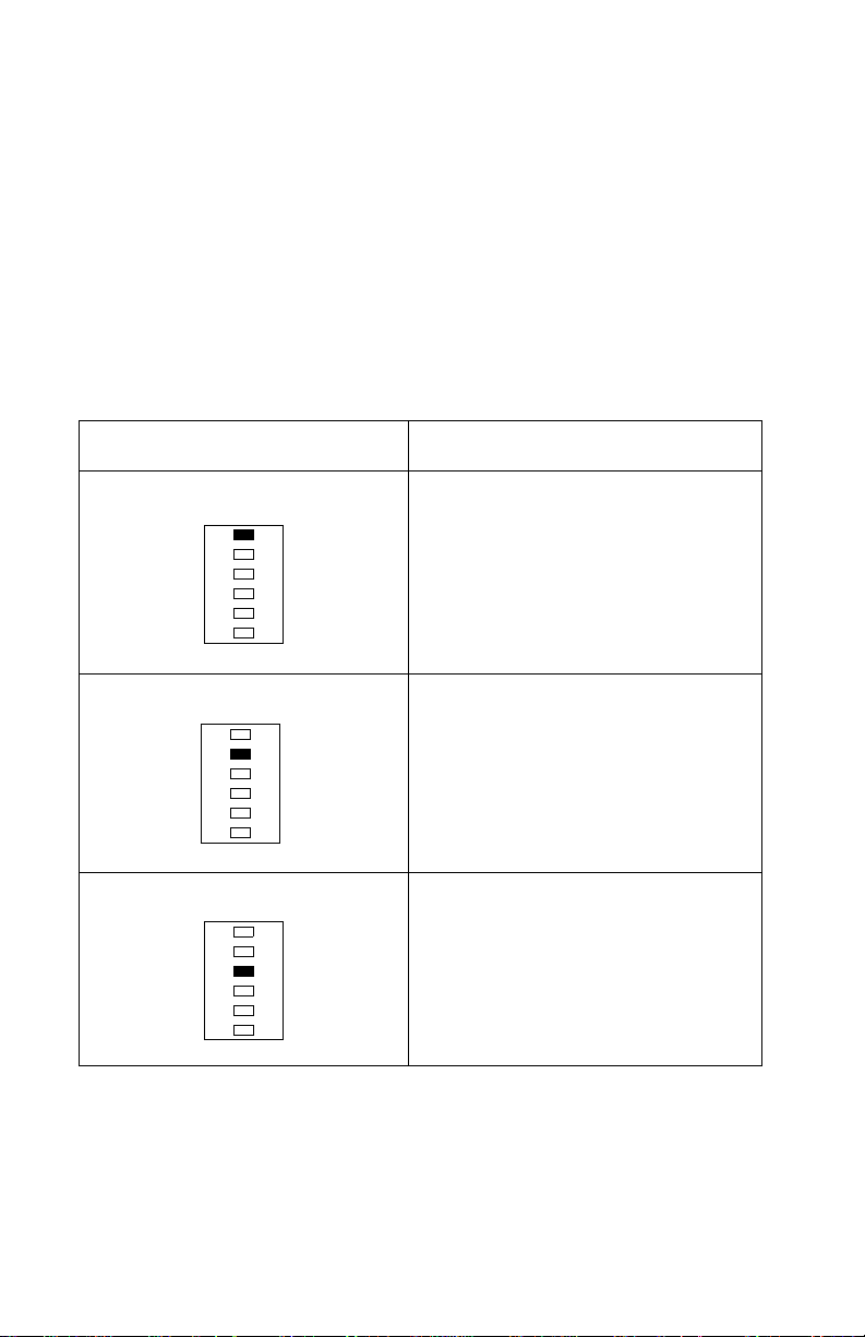
Blinking Operator Panel LED Action
Software Service Error Code Run the Printer Diagnostic Test to
.
diagnose between the R O M SIMM
and the controller board. If no other
error code displays after the test
completes, replace the controller
board.
take
Fuser Failure Error Press and release the operator
Laser Diode Failure Inspect the printhead cable and
panel button to view the secondary
service error code. Go to
“Secondary Service Error Codes” on
page 2-5.
replace as necessary. Replace the
printhead assembly. If this does not
correct t he problem, replace the
engine/LVPS board.
2-2 Service Manual
Page 25
4044-XXX
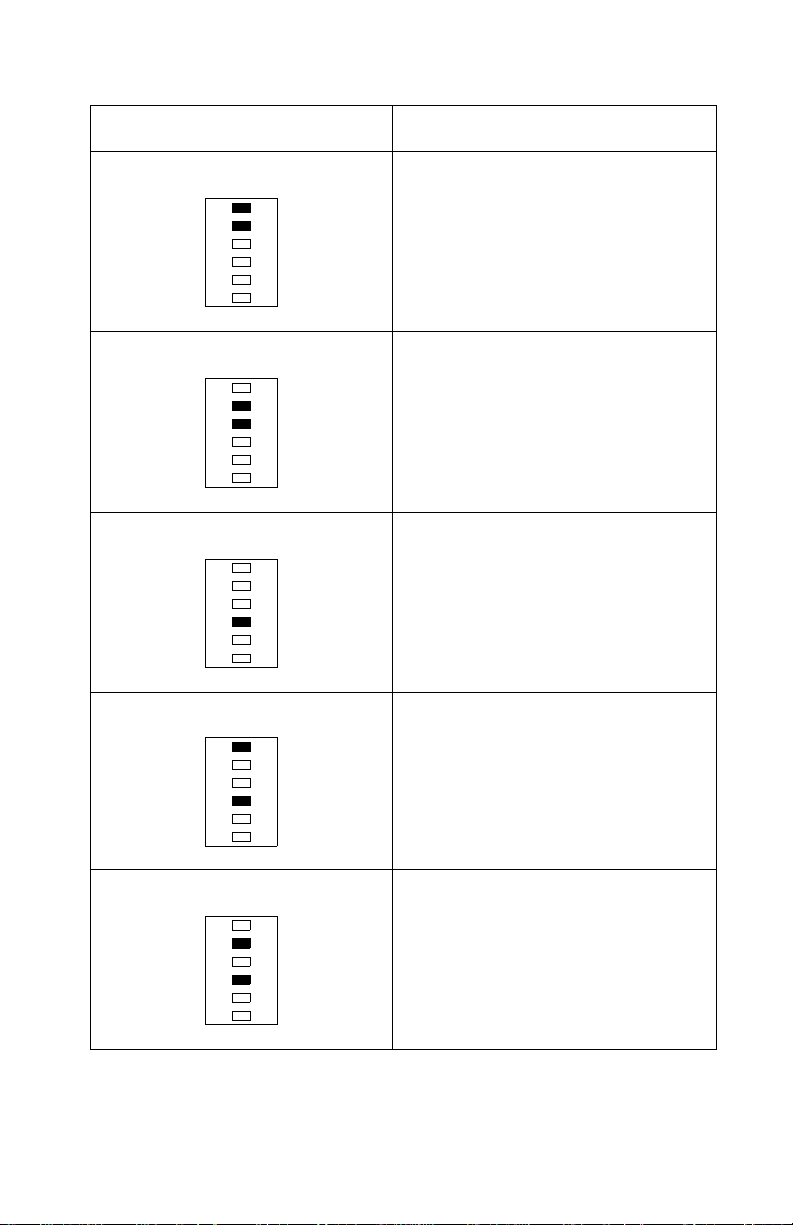
Blinking Operator Panel LED Action
Mirror Motor Failure Inspect the printhead cable and
Optional Memory Error Replace the op tional m emory SIMM.
ROM Checksum Error Replace the ROM SIMM. If this does
Base Memory Error Replace the controller board
replace as necessary. Replace the
printhead assembly. If this does not
correct the problem, replace the
engine/LVPS board.
If this does not correct the problem,
replace the controller board.
not correct the problem, replace the
controller board.
NVRAM Failure Error Replace the controller board
Diagnostic Information 2-3
Page 26
4044-XXX
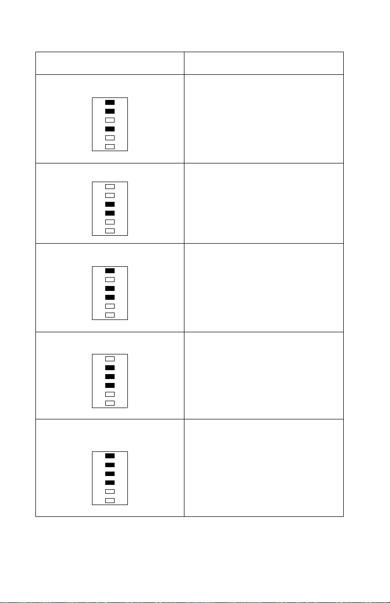
Blinking Operator Panel LED Action
ASIC Register Failure Error Replace the controller board
ASIC SRAM Failure Error Replace the controller board
Flash Memory Failure Error Replace the ROM SIMM w/Flash. If
Font Checksum Fai lure Error Replace the ROM SIMM. If this does
Engine/LVPS Board
Communications Failure Error
this does not correct the problem,
replace the controller board.
not correct the problem, replace the
controller board.
Replace the engine/LVPS board
2-4 Service Manual
Page 27
4044-XXX
Secondary Service Error Codes
For some service error codes, a second service error code is used
to further describe the error. When a service error occurs, pressing
the operator panel button after viewing the primary service error
code displays the secondary service error code. The following table
contains the secondary service error codes.
Blinking Operator Panel LED Action
Fuser Failure - Over Temperature Go to the “Hot Fuser Service Check”
Fuser Failure - Under
Temperature
Fuser Failure - Thermistor Open Go to the “Fuser Service Check” on
on page 2-21.
Go to the “Cold Fuser Service
Check” on page 2-17.
page 2-17.
Diagnostic Information 2-5
Page 28

4044-XXX
User Error Messag e Table
Primary User Error Message Table
When a user error message occurs the printer stops printing and
one or two operator panel LEDs are on solid or blinking until the
printer is powered off. Locate the printer’s LED Status in the
following table and take the indicated action.
User Error Message LED Status Action
Paper Jam Paper Jam on solid Open cover and clear
Load Manual Paper/
Envelope
Load Paper/Load
Envelope
Load Paper b links and
Press Button on solid
Load Paper on solid
and Press Button on
solid
any paper jams . Close
the top cover. If the
error message is still
present, go to
the“Paper Feed
Service Check” on
page 2-24.
Load media into the
manual slot and push
the operator panel
button to resume
printing one sheet or
do an operator panel
reset by pressing and
holding the operator
panel button for more
than three seconds.
Load media in the
appropriate paper tra y
and push the operat or
panel button to
resume printing or do
an operato r panel
reset by pressing and
holding the operator
panel button for more
than three seconds.
Top Cover Open Error on solid Close the top cover. If
the error LED remains
on solid and POST
does not continue, go
to the “Cover Open
Switch Service
Check” on page2-13.
2-6 Service Manual
Page 29

4044-XXX
User Error Message LED Status Action
Memory Full/Complex
Page/Resolution
Reduction Warning/
Font Error/ Resource
Save Off Deficient
Memory
Flash Memory Full Error blinks and Press
Error on solid and
Press Button on solid
Button on solid
The printer memory is
full or the page is too
complex to print. The
printer is forced to
reduce the resolution
of a formatted page to
300 dpi before
printing, or the printer
is unable to maintain
the required data
transfer rate. Go to the
“Secondary User
Error Message Table”
on page 2-8.
This condition only
occurs when the
Flash memory is full.
Diagnostic Information 2-7
Page 30

4044-XXX
Secondary User Error Message Table
Press and release the operator panel button two times to display the
user secondary error LED status. Each press and release action
must be performed within a half second. Locate the printer’s LED
status in the following table and take the indicated action.
User Error Message LED Status Action
Complex Page Ready, Error, and
Press Button on solid
Memory Full Ready, Data, Error,
and Press Button on
solid
Resolution Reducti on Ready, Data blinking
and the Error, Press
Button on solid
Switch the printing
mode to a different
printing mode using
the Lexmark driver f or
Windows, or push the
operator panel button
to resume printing, or
do an operator panel
reset by pressing and
holding the operator
panel button for more
than three seconds.
Change the printing
mode to Quick P rint
Plus or reduce the
complexity of the job
or the resolution, or
push the operator
panel button to
resume printing, or do
an operato r panel
reset by pressing and
holding the operator
panel button for more
than three seconds.
Switch from the GL/2
or raster mode to
Quick Print Plus m ode
using the Lexmark
driver for Wind o ws, or
press the operator
panel button to
resume printing, or do
an operato r panel
reset by pressing and
holding the operator
button for more than
three seconds.
2-8 Service Manual
Page 31

4044-XXX
User Error Message LED Status Action
Font Error Data blinking and
Resource Save Off
Deficient Memory
Error, Pre ss Button on
solid
Ready blinking and
Error, Pre ss Button on
solid
The print command is
requesting a font that
is not present or
installed. The user
must select a di ff erent
font or try turning the
Best Fit setting on and
retry the print
command.
The printer lacks
sufficient memory to
enable Resource
Save. It is
recommended that
the user install
additional memory or
set each link buffer to
the Auto va lue.
Power-On Self Test (POST)
When you turn the printer On, it performs a Power-On Self Test.
Check for correct POST functioning of the base printer by observing
the following:
1. All LEDs turn on solid.
2. All LEDs turn off.
3. The cooling fan and fuser lamp turn on.
Note: The fuser lamp turns off once the thermistor reaches
operating temperature. As the temperature drops, the lamp
turns back on automatically.
4. The LEDs begin to turn on then off sequentially.
5. Once the fuser has reached operating temperature, the main
motor turns on and the pick roller shaft assembly rotates to
home position.
6. The Ready LED turns on solid while the Data LED blinks.
7. The engine/LVPS board checks the status of the input and exit
paper feed sensors.
8. The main motor turns off.
9. The Data LED turns off.
Diagnostic Information 2-9
Page 32

4044-XXX
Symptom Ta bles
POST Symptom Table
Symptom Action
The main motor, cooling fan and
fuser do not come on.
POST completes except one or
more LEDs do not come on.
None of the LEDs come on. Go to the “Operator Panel Service
Main motor does not come on. Go to the “Main Motor Service
Fan does not come on. Go to the “Cooling Fan Ser v ice
Fuser lamp does not come on. Go to the “Cold Fuser Service
Fuser lamp never turns off. Go to the “Hot Fuser Service Check”
The paper feed picks and tries to
feed paper.
Go to “Cover Open Switch Service
Check” on page 2-13.
Go to the“Operator Panel Service
Check” on page 2-23.
Check” on page 2-23.
Check” on page 2-21.
Check” on page 2-12.
Check” on page 2-17.
on page 2-21.
Go to the “Paper Feed Service
Check” on page 2-24.
Base Printer Symptom Table
Symptom Action
Dead Machine (no power) Go to the “Dead Machine Service
Fan noisy or not working Go to the “Cooling Fan Servi ce
Fuser parts melted Go to the “Hot Fuser Service Check”
Fuser lamp doesn’t light Go to “Cold Fuser Service Check” on
Toner not fused to the paper Go to “Cold Fuser Service Check” on
Check” on page 2-14.
Check” on page 2-12.
on page 2-21.
page 2-17.
page 2-17.
2-10 Service Manual
Page 33

4044-XXX
Symptom Action
Blank page Go to “Blank page” on page 2-28.
Black page Go to “Black page” on page 2-29.
Heavy background Go to “Heavy background” on
page 2-30.
Light pri nt Go to “Light print” on page 2-33.
White or black lines or bands Go to “White or black lines or bands”
on page 2-34.
Toner on back of page Go to “Toner on back of page” on
Incorrect characters print Go to “Incorrect characters print” on
Pap er jams Go to “Paper Feed Service Check”
Main Motor noisy or does not
move
Paper never picks Go to “Paper never picks” on
Paper feeds continuously Go to “Paper picks during POST
Pap er skew Go to “Paper Feed Service Check”
Printer not communicating with
host
Paper wrinkled or bent Go to “Paper "trees", wrinkles,
Top cover will not close Go to “Cover Open Switch Service
page 2-34.
page 2-34.
on page 2-24.
Go to “Main Motor Service Check”
on page 2-21.
page 2-27.
and/or continuously” on page 2-25.
on page 2-24.
Go to “Parallel Port Service Check”
on page 2-35.
stacks poorly or curls” on page 2-28.
Check” on page 2-13.
Operator panel button does not
respond
Operator panel LEDs do not light
or very dim
Go to “Operator Panel Button
Service Check” on page 2-24.
Go to “Operator Panel Service
Check” on page 2-23.
Diagnostic Information 2-11
Page 34

4044-XXX
Service Checks
Note: All service checks which involve measuring voltages of the
circuit boards (except the controller board) must be performed with
the engine/LVPS to controller board cable disconnected and the
printer positioned on its left side. This provides the servicer access
to the various circuit boards underneath the printer while supplying
necessary power to the rest of the printer.
Cooling Fan Service Check
FRU Action
Model E310
Interconnect Board
Cooling Fan
FRU Action
Model E312
Engine Board
Cooling Fan
Make sure moto r cable is properly
seated in location CN408 on the
interconnect board. Disconnect the
cable and check connector-pin
CN408-3 for +24 V dc. If the voltage
is not present, replace the
interconnect board. If the voltage is
present, replace the cooling fan.
Make sure moto r cable is properly
seated in location C N3 on the engine
board. Disconnect the cable and
check connector-pin CN3-1 for +24
V dc. If the voltage is not present,
replace the engine board. If the
voltage is present, replace the
cooling fan.
2-12 Service Manual
Page 35

4044-XXX
Cover Open Switch Service Check
Note: Make sure a toner cartridge is installed and the cover closes
all the way, engaging the cover open switch lever. The lever can
easily be positioned incorrectly if the top cover has been removed
and replaced.
FRU Action
Models E310 & E312
Cover Open Switch
Model E310
HVPS
Engine/LVPS Board
Make sure the cover open switch
cable is properly seated in CN2 of
the HVPS. Disconnec t the cabl e and
check the switch for continuity. Push
the cover open switch lever down to
engage the switch and close the
circuit. If the circuit does not close,
replace the switch.
Measure the volta ge at CN2-3 of the
HVPS. It measures +24 V dc. If
voltage is present at CN2-3, check
for continuity between CN2-1 and
CN1-2. If continuity does not exist,
replace the HVPS. If continuity does
exist, check the HVPS to engine/
LVPS board cable for continuity.
Replace if defective. If voltage is not
present at CN2-3, chec k the voltage
at CN1-1. It measures +24 V dc. If it
does, replace the HVPS. If it does
not, check the voltage at CN2-2 of
the engine/LVPS board. It measures
+24 V dc. If it does, replace the
HVPS to engine/LVPS board cable.
Diagnostic Information 2-13
Page 36

4044-XXX
FRU Action
Model E312
HVPS
Model E312
HVPS to Engine Board Cable
E312
Engine Board
Measure the voltages at CN2 of the
HVPS. CN2-3 measures +5 V dc
and CN2-4 measures +24 V dc. If
the correct voltage is present, check
the continuity between the following
connector locations:
CN2-3 - CN1-17
CN2-3 - CN1-19
CN2-4 - CN1-2
CN2-4 - CN1-4
If any location does not measure
continuity, replace th e HVPS.
Replace the cable if it does not
measure continuity.
Go to the “Engine Board (model
E312)” on page -9. Measure the
voltages on CN11. If an y voltages
are incorrect, replace the engine
board.
Dead Machine Service Check
Note: Check the AC line voltage. The voltage should be within the
following limits:
100 V ac - 127 V ac for the low voltage model printer
200 V ac - 240 V ac for the high voltage model printer
FRU Action
Model E310 & E312
LVPS Fuse
Check the fuse on the LVPS for
continuity. Replace with the
appropriate fuse if blown. If a fuse
blows again after being rep laced,
install a new fuse and go to “Engine/
LVPS Board (model E310)” on
page 5-4 and check the engine/
LVPS board output.
2-14 Service Manual
Page 37

4044-XXX
FRU Action
Model E310
Engine/LVPS Board
Power Switch
Model E310
LVPS to Interconnect Board
Cable
Model E310
Interconnect Board
Disconnect the ca bles from C N2 and
CN5 and leav e the cab les conn ected
to the power switch attached. With
the prin ter position ed on its left side
and the engine/LVPS board
positioned on a flat surface, turn the
power switch on and check the AC
line voltage at connector CN201. If
no voltage is present, replace the
power switch. If line voltage is
present, measure the voltages at
connectors CN2 and CN5. Go to
the“Engine/LVPS Board (model
E310)” on page 5-4 and check for
correct voltage measurements.
Replace the engine/LVPS board if
any of the voltage measurements
are incorrect.
Check the continuity of the LVPS to
interconnect board cable. Replace
the cable if it does not measure
continuity.
Reconnect the LVPS to the
interconnect board cable. Go to
“Interconnect Board (model E310)”
on page 5-21 and measure voltages
on the following connectors on the
interconnect board:
Model E312
Power Switch
CN401/CN402/CN403/CN404/
CN405/CN407/CN408
If any of the measured voltages are
incorrect, replace the interconnect
board.
Place the printer on its rear side.
Position the LVPS board on a flat
surface with all the cables
connected. Turn the printer power
switch to the on position. Check the
AC line voltage at power switch
connector CN501. If no voltage is
present, replace the pow er switch
Diagnostic Information 2-15
Page 38

4044-XXX
FRU Action
Model E312
LVPS Board
Model E312
Engine Board
Disconnect the LVPS cable from
connector CN7 on the en gine bo ard.
Go to the “LVPS (model E312)” on
page -14. Check the voltage
measurements at co nne ctor C N503.
If any voltage measurements are
incorrect, replace the LVPS.
Reconnect the LVPS cable to
connector CN7 on the en gine bo ard.
Disconnect all other cables from the
engine board. Go to the “Engine
Board (model E312)” on page -9.
Check the voltage measurements at
each connector. If any voltages are
incorrect, replace the engine board.
If all voltages are correct, reconnect
all the cables to the engine board
one at a time. Check the voltage
meausrements on the engine board
each time you connect a cable. If a
voltage measurement is incorrect
after connecting one of the cables,
replace the FRU that you connected.
2-16 Service Manual
Page 39

4044-XXX
Fuser Servic e Check
Cold Fuser Service Check
When toner is partially fused to the paper, it is usually caused by low
fuser temperature.
Avoid handling the lamp as much as possible as it is easily broken.
Be careful not to touch the glass housing with bare hands as skin
contains acids that can weaken the glass.
The line voltage to the printer must be within the following limits:
100 V ac - 127 V ac for the low voltage model printer
200 V ac - 240 V ac for the high voltage model printer
Turn the printer off and wait a few minutes for the fuser lamp to cool.
Turn the machine on and observe the lamp turning on during POST .
You can see the lamp with the left side cover and fuser wire cover
removed.
Diagnostic Information 2-17
Page 40

4044-XXX
The fuser lamp does light
FRU Action
Model 310
Thermistor
Model 312
Thermistor
If the fuser lamp comes on and a
fuser failure LED error code displ ays,
be sure the thermistor is contacting
the hot roll and the thermistor cable
is firmly seated in c on nec tor C N1 on
the L VPS board. Check fo r excessiv e
toner buildup on the surface of the
thermistor. Clean or replace as
necessary. Turn the printer off and
disconnect the t hermistor c ab le fro m
CN1 on the LVPS board. Measure
the resistance of the thermistor
between CN1-1 and CN1-2. The
resistance measures approximately
225K ohms when cool. Replace the
thermistor as necessary.
If the fuser lamp comes on and a
fuser failure LED error code displ ays,
be sure the thermistor is contacting
the hot roll and the thermistor cable
is firmly seated in connector CN10
on the engine board. Check for
excessive toner buildup on the
surface of the thermistor. Clean or
replace as necessary. Turn the
printer off and disconnect the
thermistor cable from CN10 on the
engine board. Measure the
resistance of the thermistor betw een
CN10-1 and CN10-3. Th e resistance
measures appro ximatel y 225K ohm s
when cool. Replace the thermistor
as necessary.
Models E310 & E312
Fuser Lamp
2-18 Service Manual
Make sure the correct vo lta ge lam p
is installed. The voltage rating is
stamped on one of the lamp
contacts.
Page 41

4044-XXX
The fuser lamp does not light
FRU Action
Model E310
Fuser Lamp
Lamp Cable
Thermistor
LVPS
Tur n the printer off and disconnect
the fuser lamp wires from the fuser.
Check for continuity across the fuser
lamp wire contacts. If there is
continuity, go to step 1: Continuity.
If there is no continuity, go to
step 2: No Continuity.
Step 1: Continuity
Measure the voltage at connector
CN202 on the LVPS. It should match
the line voltage. If it does not,
replace the LVPS. If line voltage is
present, check the fuser lamp cable
for continuity. Replace if
defective.Make sure the fuser
thermistor is correctly connected to
CN1 on the LVPS. If the problem
persists, disconnect the thermistor
cable from CN1 on the LVPS board
and measure the vol tag e between
CN1-1 and ground. The voltage
measures approximately 3.9 V dc. If
the voltage is incorrect, replace the
LVPS. If correct, replace the
thermistor.
Step 2: No Continuity
Check the thermal fuse f or contin uity .
If incorrect, replac e the t hermal fuse .
If correct, replace the lamp.
Diagnostic Information 2-19
Page 42

4044-XXX
FRU Action
Model E312
Fuser Lamp
Lamp Cable
Thermistor
LVPS
Turn the printer off and disconnect
the fuser lamp wires from the fuser.
Check fo r contin uity acros s the fuse r
lamp wire contacts. If there is
continuity, go to step 1: Continuity.
If there is no continuity, go to
step 2: No Continuity.
Step 1: Continuity
Measure the voltage at connector
CN502 on the LVPS. It should match
the line voltage. If it does not,
replace the LVPS. If line voltage is
present, check the fuser lamp cable
for continuity. Replace if
defective.Make sure the fuser
thermistor is correctly connected to
CN10 on the engine board. If the
problem persists, disconnect the
thermistor cable from CN1o on the
engine board and measure the
voltage between CN10-1 and
ground. The voltage measures
approximately 3.9 V dc. If the voltag e
is incorrect, replace the engine
board. If correct, replace the
thermistor.
Step 2: No Continuity
2-20 Service Manual
Check the thermal fuse f or contin uity .
If incorrect, replace the thermal f use.
If correct, replace the lamp.
Page 43

4044-XXX
Hot Fuser Service Check
FRU Action
Model E310
Fuser Thermistor
Model E312
Fuser Thermistor
Models E310 & E312
Fuser Lamp
Disconnect the the rmistor cable from
the LVPS. Measure the resistance
across CN1-1 and CN1-2 of the
thermistor cable. Replace the
thermistor if the resistance is low er
than 1k ohm or shorted.
Disconnect the the rmistor cable from
the engine board. Measure the
resistance across CN10-1 and
CN10-3 of the thermistor cable.
Replace the thermistor if the
resistance is lower than 1k ohm or
shorted.
Make sure the correct voltage fuser
lamp is insta lled. Replace if
necessary.
Main Motor Service Che ck
FRU Action
Model E310
Interconnect Board
Main Motor
Main Motor Cable
Check the in terconnec t board f or the
following voltages:
CN405-3 +24 V dc
CN405-4 +24 V dc
If these voltages are not correct,
replace the interconnect board. If
these voltag es are correct, check the
main motor cable for continuity. If
continuity exists on each wire,
replace the main motor. If continuity
does not exist on one or more of the
wires, replace the cable.
Diagnostic Information 2-21
Page 44

4044-XXX
FRU Action
Model E312
Engine Board
Main Motor
Main Motor Cable
Check the engine board for the
following voltages:
CN2-3 +24 V dc
CN2-4 +24 V dc
If these voltages are not correct,
replace the engine board. If these
voltages are co rrec t, ch eck the main
motor cable for continuity. If
continuity exists on each wire,
replace the main motor. If continuity
does not exist on one or more of the
wires, replace the cable.
2-22 Service Manual
Page 45

4044-XXX
Operator Panel Service Check
Inspect the operator panel cable for damage. Make sure the cable is
plugged in securely.
Run POST and check each LED for proper operation.
FRU Action
Models E310 & E312
Operator Panel
Operator Panel Cable
Models E310 & E312
Operator Panel
Operator Panel Cable
Controller Board
If more than one LED does not turn
on or an individual LED stays on
solid during POST, check the
operator panel cable for continuity.
Replace if defective. If the cable
measures continuity, replace the
operator panel.
If all LEDs are dim and operate
erratically during POST or all LEDs
come on and stay on solid during
POST, replace the following FRUs
one at a time in the order shown:
Controller Board
Operator Panel
Operator Panel Cable
If none of the LEDs come on, make
sure the cable is properly connected
to the operator panel and the
controller board. Disconnect the
cable and check it for continuity.
Replace if necessary. If the cable
measures continuity, measure the
followi ng v oltag es wit h the printer on
at idle:
U5-1: Ground
U5-2: +5 V dc
U5-3: +5 V dc
U5-5: +5 V dc
U5-6: Ground
If these voltages are not correct,
replace the controll er bo ard. If thes e
voltages are correct, replace the
operator panel.
Diagnostic Information 2-23
Page 46

4044-XXX
Operator Panel Button Service Check
FRU Action
Models E310 & E312
Operator Panel
Operator Panel Cable
Disconnect the operator panel from
the operator panel cabl e . Check the
continuity between U5-1 and U5-2
on the operator panel as you press
the operator panel button. As the
button is pressed, continuity is
present. Replace the operator panel
if continuity is not present. If
continuity is present, replace the
operator panel cabl e .
Paper Feed Service Check
Paper Jam error indication during POST
FRU Action
Models E310 & E312
Exit Sensor Flag
Models E310 & E312
Input Paper Feed Sensor
If the exit sensor flag is not resting
within the paper exit sensor during
POST, the printer displays a paper
jam message. M ake sure the flag is
operating freely and correctly
installed.
Make sure the input paperfeed
sensor is working properly. A stuck
or incorrectly installed sensor
causes this error.
2-24 Service Manual
Page 47

4044-XXX
Paper picks during POST and/or continuously
FRU Action
Models E310 & E312
Pick Roller Clutch
Solenoid
Check the pick roller clutch for wear.
The solenoid interac ts with the
clutch controlling motion of the pick
roller. If the cam surface of the pick
roller clutch assembly is worn, the
solenoid ma y not sto p the pick roller
from rotating. Repla ce the pick roller
clutch assembly if necessary. Make
sure the spring on the solenoid is
properly installed. If the spring is
improperly installed or missing, the
pick roller will continuously pick
paper.
Paper picks but stops about an inch down the page
FRU Action
Models E310 & E312
Roller Guides
Check for correct position of roller
guides on pick roller assembly.
Paper picks but stops half way through the printer
FRU Action
Model E310
Input Paper Feed Sensor
Interconnect Board
Make sure the input paper feed
sensor is working properly. Check for
a broken or stuck flag on the input
paper feed sensor. Check to make
sure the cable is seated on the
CN401 connector on the
interconnect board. Disconnect the
cable and check for the following
voltages:
CN401-3 +5 V dc
CN401-4 Ground
If these voltages are not correct,
replace the interconnect board. If
correct, replace the in put paper feed
sensor.
Diagnostic Information 2-25
Page 48

4044-XXX
FRU Action
Model E312
Input Paper Feed Sensor
Engine Board
Make sure the input paper feed
sensor is working properly. Check for
a broken or stuck flag on the input
paper feed sensor. Check to make
sure the cable is seated on the CN6
connector on the engine board.
Disconnect the cable and check for
the following v oltages:
CN6-3 +5 V dc
CN6-4 Ground
If these voltages are not correct,
replace the engine board. If correct,
replace the input paper feed sensor.
2-26 Service Manual
Page 49

4044-XXX
Paper never picks
FRU Action
Models E310 & E312
Pap er Tray
Model E310
Pick Roller Solenoid
Model E312
Pick Roller Solenoid
Make sure the p ape r t ray is correc tly
installed. The black mylar guide
sheet in the front of the tray must be
positioned in the paper path just
behind the pick rol ler a ss em bly. This
guide sheet can easily block the
paper path if installed incorrectly.
Make sure solenoid is installed
correctly and its cab le is plugged into
CN402 on the interconnect board. If
installation is correc t, disco nnect the
solenoid and check CN402-1 for
+24 V dc. If the voltage is present,
replace the solenoid. If the vo ltage is
not present, replac e the interco nnect
board.
Make sure solenoid is installed
correctly and its cab le is plugged into
CN4 on the engine board. If
installation is correc t, disco nnect the
solenoid and check CN4-1 for
+24 V dc. If the voltage is present,
replace the solenoid. If the vo ltage is
not present , replace the engine
board.
Paper occasionally picks or picks multiple sheets at once
FRU Action
Models E310 & E312
Pick Roller Assembly
Models E310 & E312
Paper Separator Assembly
Models E310 & E312
Pick Roller Pad Assembly
Check pick roller assembly for wear.
Replace as necessary.
Check the friction pad on the paper
separator for signs of wear. Replace
as necessary.
Check the friction pad on the pick
roller pad assembly for signs of
wear. Replace as necessary.
Diagnostic Information 2-27
Page 50

4044-XXX
Paper "trees", wrinkles, stacks poorly or curls
FRU Action
Models E310 & E312
Transfer Roller
This problem is most likely due to a
worn transfer roller. A worn transfer
roller causes the printer to run h otter
than required for the media being
printed. Excessive heat can cause
paper treeing problems, poor
stacking or curl.
Print Quality Service Check
Blank page
FRU Action
Models E310 & E312
Toner Car tridge
Printhead
Printhead Cable
HVPS
Engine/LVPS Board (Model E310)
Engine Board (Model E312)
Remove the toner cartridge and
gently shake the assembly to evenly
distribute the toner.
Blank pages can be caused by a
defective printhead assembly, high
voltage power supply or engine/
LVPS board. Disconnect the
printhead cable from the HVPS and
measure the signals on connectors
CN3 and CN4. Go to the “High
V oltage P ower Su pply (model E310 )”
on page 5-16 in the connector
locations chapter and check the
voltage measurements. If the
voltages are correct, check the
printhead cable for continuity. If the
cable measures continuity, replace
the printhead. If the cable does not
measure continuity, replace the
cable. If the voltage measurements
are not correct, replace the HVPS. If
the problem still exists, replace the
engine/LVPS board on the model
E310 or the engine board on the
model E312.
2-28 Service Manual
Page 51

4044-XXX
Black page
Note: Incorrect laser exposure or incorrect charging of the
photoconductor causes an all black page.
FRU Action
Models E310 & E312
HVPS Contacts
Model E310
Engine/LVPS Board
HVPS Cable
HVPS
Model E312
Engine Board
HVPS Cable
HVPS
Check the contacts for
contamination and correct
installation. Replace as necessary.
Make sure the HVPS to engine/
LVPS cable is correctly installed.
Disconnect the cable and measure
the signals on CN2 of the engine/
LVPS board. Go to “Engine/LVPS
Board (model E310)” on page 5-4
and check the voltage
measurements. If the voltages are
not correct, replace t he engine/LVPS
board. If the voltages are correct,
check the HVPS to engine/LVPS
cable f o r co nti n ui ty. If the cable does
not measure continuity, replace the
cable. If the cable measures
continuity, replace the HVPS.
Make sure the HVPS to engine
board cable is correctly installed.
Disconnect the cable and measure
the signals on CN11 of the engine
board. Go to the “Engine Board
(model E312)” on page-9. Check
the voltage measurements. If the
voltages are not cor rect, replace the
engine board. If the voltages are
correct, check the HVPS to engine
board cable for continuity. If the
cable does not measure continuity,
replace the cable. If the cable
measures continuity, replace the
HVPS.
Diagnostic Information 2-29
Page 52

4044-XXX
Heavy background
Poor dev elopment or poorly charged toner particles cause excessive
background. This is more noticeable as the toner cartridge nears
end of life.
FRU Action
Models E310 & E12
Toner Car tridge
Model E310
HVPS Contacts
HVPS Board
Engine/LVPS Board
Model E312
HVPS Contacts
HVPS Board
Engine Board
Make sure toner cartridge is
correctly installed and the high
voltage contacts are clean. If the
cartridge is installed correctly, try a
new cartridge.
Check the contacts for correct
installation and co ntamination where
contact is made with the toner
cartridge and HVPS Board. Clean as
necessary. If this does not correct
the problem, replace the following
FRUs one at a time in the order
shown:
HVPS Board
Engine/LVPS Board
Check the contacts for correct
installation and co ntamination where
contact is made with the toner
cartridge and HVPS Board. Clean as
necessary. If this does not correct
the problem, replace the following
FRUs one at a time in the order
shown:
HVPS Board
Engine Board
2-30 Service Manual
Page 53

4044-XXX
Partial blank image/white spots (no periodic pattern)
FRU Action
Toner Cartridge Remove the toner cartridge and
Fuser Backup Roller Springs Check left and right backup roller
Paper Make sure recommended paper is
gently shake the assembly to evenly
distribute the toner. If toner cartridge
is low, try a new one.
springs and backup roller to ensure
adequate e ven pressu re is applied to
the fuser hotroll.
being used.
Variation in image density horizontally across page
FRU Action
Toner Cartridge The charge roll in the toner cartridge
Transfer Roller Bearing Assembly
Transfer Roller
may have an unbalanced pressure
against the PC drum. Try a new
toner cartridge.
Check the springs in the left and
right transfer roller bearings. The
bearing assemblies should support
the transfer roller, applying even
pressure to the PC drum. Replace
either or both transfer roller bearing
assemblies if the springs show signs
of damage or fatigue. Inspect the
transfer roller for signs of wear or
damage and replace as necessary.
Diagnostic Information 2-31
Page 54

4044-XXX
Periodic irregularity down pa ge
FRU Action
PC Drum (Toner Cartridge)
Distance Between Irregularity
94.5 mm
Charge Roller (Toner Cartridge)
Distance Between Irregularity
37.8 mm
Supply Roller (Toner Cartridge)
Distance Between Irregularity
40.1 mm
Develo per Ro ll er
(Toner Cartridge)
Distance Between Irregularity
46.1 mm
Transfer Roller
Distance Between Irregularity
46.0 mm
Hot Roll
Distance Between Irregularity
56.7 mm
The PC drum or gear driving the PC
drum may be contaminated or
damaged. Inform the customer to
replace the toner cartridge.
The charge roller or gear driving the
charge roller may be contaminated
or damaged. Inform the customer to
replace the toner cartridge.
The supply roller or gear driving the
supply roller may be contaminated or
damaged. Inform the customer to
replace the toner cartridge.
The supply roller or gear driving the
developer roller may be
contaminated or damaged. Inform
the customer to replace the toner
cartridge.
The transfer rol ler or gear driving the
transfer roller may contaminated or
damaged. Inspect the roller and
gear. Replace as necessary.
The hot roll of the fuser or gear
driving the hot roll may be
contaminated or damaged. Inspect
the hot roll and gear. Replace or
clean as necessary.
Backup Roller
Distance Between Irregularity
69.1 mm
2-32 Service Manual
The backup roller of the fuser may
be contaminated or damaged.
Inspect and replace as necessary.
Page 55

4044-XXX
Poor fusing of image
FRU Action
Fuser Lamp The fuser may not be operating at
Paper Make sure recommended paper is
the proper temperature to fuse the
toner to the paper . Go to the “Cold
Fuser Service Check” on page 2-17.
being used.
Light print
FRU Action
Toner Cartridge Make sure the toner cartridge is
installed correctly and is not low on
toner. If the problem continues,
install a new toner cartridge.
Transfer Roller
HVPS Contact (Transfer Roller)
HVPS Board
Check the transfer roller for signs of
toner buildup and contamination.
Inspect the HVPS contact (transfer
roller) for contamination. Inspect the
HVPS board for contamination
where it meets the HVPS contacts. If
all components appear free of
contamination, replace the following
FRUs one at a time in the order
shown:
Transfer Roller
HVPS Contact (Transfer Roller)
HVPS Board
Diagnostic Information 2-33
Page 56

4044-XXX
White or black lines or bands
FRU Action
Toner Car tridge
Paper Feed Drive Gears
Banding appears as light or dark
horizontal lines on a uniformly gray
page or on a page with a large area
of graphics . Bandin g is prima rily due
to a variation in the speed of the
paper as it feeds through the printer
especially in the developer and
transfer process. Inspect the toner
cartridge and paper feed
components, especially the drive
gears, for signs of wear, debris,
binds or damage.
Toner on back of page
FRU Action
Print Cartridge Inspect the overall paper path for
signs of spilled toner. Gently clean
the contaminated areas with a soft
cloth or compressed air.
Fuser Hot Roll
Backup Roller
The fuser hot roll can c ause tone r on
the back of the paper if toner is
building up on the hot roll. This
buildup may transfer to the backup
roller, later transferring to the
backside of the paper. Inspect the
hot roll and back up roll er for signs of
contamination and replace as
necessary.
Transfer Roller A transfer roller contaminated with
toner can cause toner to transfer to
backside of printed pages. Inspect
the transfer roller for contamination
and replace as necessary.
Incorrect characters print
Make sure the correct printer driver software is installed. Incorrect
software can cause incorrect characters to print and the image may
not fit the page.
2-34 Service Manual
Page 57

4044-XXX
Parallel Port Service Check
1. Perform a print test to make sure the printer prints correctly.
2. Be sure the printer cable is designed for bidirectional printing.
3. Be sure the user application is set up correctly. Improper set up
can prevent establishing a communication link with the printer.
4. Try enabling the parallel port pull-up resistors. Go to
Mode 1” on page 3-8
resistors. If the printer still does not print, disable the resistors.
5. If the internal print test page prints correctly, the user
application/printer driver is set up correctly and the correct bidirectional parallel cable is installed, yet the printer still fails to
print on command from the host, replace the controller board.
. Try printing a test page after enabling
“Parallel
Diagnostic Information 2-35
Page 58

4044-XXX
2-36 Service Manual
Page 59

4044-XXX
3. Diagnostic Aids
This chapter explains the tests and procedures you can run to
identify printer failures and verify that repairs have corrected the
problem.
Memory Test
The following tests run sequentially when performing this test:
Standard Memor y Test
Optional Memory Test
The memory test runs automatically during POST if a different size
optional memory SIMM is installed since the last printer power on.
Perform the following steps to run the Memory Test:
1. Turn the printer off.
2. Open the top cover.
3. Press and hold the operator panel button as you turn on the
printer. Release the button once the Error LED comes on solid.
4. Close the top cover.
5. If all the diagnostic tests run correctly, the Data LED blinks. If a
test fails, the Error LED pattern for the service error code displays on the operator panel. Go to the “Service Error Codes” on
page 2-2 and take the indicated action for that error.
Diagnostic Test
Once the memory test is complete, the diagnostic test pages can be
printed by briefly pressing the operator panel button. Two pages are
printed. The first page is a listing of various printer settings and code
level. The second page is used to inspect registration. If the printer
requires a registration adjustment, you must contact your next level
of support to obtain the software utility that enables you to adjust
registration.
Diagnostic Aids 3-1
Page 60

4044-XXX
Print Quality Test
There are three print quality test pages. The first page displays the
installed printer base code level and user default settings for the
following:
Top Margin Offset
Left Margin Offset
Printer Page Count
Installed Memory
PQET Setting (on/off)
Toner Saver (on/off)
Print Resolution
Print Darkness
The next two test pages are used to evaluate print quality. One test
page is gray and the other is black. Perform the following steps to
print the second test page:
1. Turn the printer off.
2. Open the top cover.
3. Turn the printer power on.
4. When the Error LED comes on solid, double-click the operator
panel button.
5. Once the Error and Press Button LEDs start blinking, close the
top cover.
6. The Ready LED comes on solid and the Error and Press Button
LED continue blinking.
7. Double-click the operator button four times. The Ready and
Data LEDs come on solid while the Error and Press Button
LEDs continue blinking.
8. Perform a long button press until all LEDs come on solid.
9. The test pages are printing.
10. When the test pages have finished printing, the Ready LED
comes on solid and the Data LED goes off.
Note: After the print quality test pages print, the printer automatically returns to the Ready mode.
3-2 Service Manual
Page 61

4044-XXX
User Mode Print Test
The User Mode Print Test Page displays the user default values ,
installed options, printer features, various typefaces, and the
installed printer base code level.
1. Turn the printer power on. The Ready LED comes on solid
(printer is in the ready state).
2. Press and release the operator panel button.
3. The Ready LED comes on solid and the Data LED blinks indicating the printer is busy.
4. The test page prints and the operator panel Ready LED comes
on solid and the Data LED turns off.
5. The printer returns to the Ready mode.
Configuration Mode
The configuration mode gives the ability to set the following printer
functions through the operator panel:
Parallel Port Settings
Enable Port
NPA Mode
Protocol
Mode 1
Mode 2
Strobe Adjust
USB Settings
Enable Port
NPA Mode
PPDS Activated
Auto CRLF/LFCR
Diagnostic Aids 3-3
Page 62

4044-XXX
Operator Panel Configuration Mode Button Definition
Term Description Result
Brief Button Press Press the operator
Long Button Press Press and hold the
Double-Click Button
Press
panel button no l onger
than three seconds.
operator panel button
for more than three
seconds.
Press and release the
operator panel button
two times. Each press
and release action
must be performed
within a half second.
This action moves
through the configuration mode settings.
This action selects
and saves the setting
for the menu item displayed. To indicate
that the setting is
saved, all LEDs blink
once.
This action moves
through the configuration mode menu.
Perform the following steps to enter the configuration mode:
1. Turn the printer power off.
2. Open the top cover.
3. Turn the printer power on.
4. When the Error LED comes on solid, double-click the operator
panel button.
5. When the Error and Press Button LEDs start blinking, close the
top cover. The Ready LED comes on solid and the Error and
Press Button LEDs continue blinking.
6. Double-click the operator panel button two times. The Load
Paper LED comes on solid while the Error and Press Button
LEDs continue blinking.
7. Perform a long button press. All LEDs blink once. The Ready
LED stays on solid. The printer is in the configuration mode.
8. To exit the configuration mode, turn the printer power off.
Configuration Mode Operator Panel Overlays
When in configuration mode, the first menu item and its setting are
displayed. The first menu item is the Parallel P ort and is indicated by
3-4 Service Manual
Page 63

4044-XXX
the solid Ready LED. The setting of the menu item is indicated by
the status of the Press Button LED. To change the menu item
setting, briefly press the operator panel button. Once the setting you
want is indicated by the status of the Pre ss Button LED, perform a
long button press to save the setting. All LEDs come on while the
setting is saved. To select other menu items, double-click the
operator panel button until the menu item LED you want is selected.
There are ten menu items that can be selected by using the five
LEDs as indicated by the following overlays on two passes through
the configuration menu. The first time through the menu the LED
selected is on solid. The second time through the menu the LED
selected is blinking.
First pass - LED on solid overlay.
Parallel Port
Parallel NPA
Parallel Protocol
PPDS
CRLF/LFCR
Off/On/Auto
Second pass - LED blinking overlay
Operator Panel Button
Parallel Mode 1
Parallel Mode 2
Parallel Strobe
USB Port
USB NPA
Off/On/Auto
Operator Panel Button
Diagnostic Aids 3-5
Page 64

4044-XXX
Configuration Mode Settings
The following is a description of the available configuration mode
menu items and settings. The asterisk (*) indicates the factory
default setting.
Parallel Port
Parallel Port allows the user to enable or disable the parallel port. If
the port is not being used, disabling it frees allocated memory to be
used to process print jobs.
Perform the following steps to change the Parallel Port setting:
1. Enter the configuration mode.
Note: The Parallel Port (Ready) LED comes on solid. The
current Parallel Port setting is indicated by the Off/On/Auto
(Press Button) LED. When the LED is off, the parallel port is
disabled. When the LED is *blinking, the parallel port is enabled.
2. Perform a brief button press to select the Parallel Port setting.
3. Perform a long button press. All LEDs blink once, indicating the
setting is saved.
4. Exit the configuration mode by turning the printer power off.
Parallel NPA
Parallel NPA mode allows two way communication between the host
and the printer.
Perform the following steps to change the Parallel NPA setting:
1. Enter the configuration mode.
2. Perform a double click button press. This moves to the Parallel
NPA item on the configuration menu. The Parallel NPA (Data)
LED comes on solid.
3. The current Parallel NPA setting is indicated by the Off/On/Auto
(Press Button) LED.
• When the LED is on solid, all data received by the printer
must be in NPA packets. Any non-packet data is rejected as
bad packets.
• When the LED is off, the printer is not performing any NPA
processing.
3-6 Service Manual
Page 65

4044-XXX
• When the LED is *blinking, the printer examines incoming
data and decides whether it is receiving NPA packets.
4. Perf orm a brief button press to select the Parallel NPA setting.
5. Perform a long button press. All LEDs blink once, indicating the
setting is saved.
6. Exit the configuration mode by turning the printer power off.
Parallel Protocol
The printer supports two parallel protocol settings: standard and
fastbytes. When the protocol is set to standard, information is
received at a normal transmission rate. When the protocol is set to
fastbytes, information can be received at a much faster transmission
rate provided the host computer supports the fastbytes mode.
Perform the following steps to change the Parallel Protocol setting:
1. Enter the configuration mode.
2. Perform a double click button press twice. This moves to the
Parallel Protocol item on the configuration menu. The Parallel
Protocol (Load Paper) LED comes on solid.
3. The current Parallel Protocol setting is indicated by the Off/On/
Auto (Press Button) LED. When the LED is off, the Parallel
Protocol is set to standard. When the LED is *on, the Parallel
Protocol is set to fastbytes. Perform a brief button press to
select the Parallel Protocol setting.
4. Perform a long button press. All LEDs blink once, indicating the
setting is saved.
5. Exit the configuration mode by turning the printer power off.
PPDS
To access the PPDS data stream, the PPDS setting must be set to
active. When PPDS is activated, the default Printer Language is
changed to PPDS and the default PCL and PostScript Smartswitch
settings are changed to Off.
Perform the following steps to change the PPDS setting:
1. Enter the configuration mode.
2. Perform a double click button press three times. This moves to
the PPDS item on the configuration menu. The PPDS (Paper
Jam) LED comes on solid.
Diagnostic Aids 3-7
Page 66

4044-XXX
3. The current PPDS setting is indicated by the Off/On/Auto (Press
Button) LED. When the LED is *off, the PPDS is set to inactive.
When the LED is on, the PPDS is set to active. Perform a brief
button press to select the PPDS setting.
4. Perform a long button press. All LEDs blink once, indicating the
setting is saved.
5. Exit the configuration mode by turning the printer power off.
CRLF/LFCR
This function controls whether or not the printer automatically
performs a carriage return after a line feed control command and
whether or not the printer automatically performs a line feed after a
carriage return control command.
Perf orm the following steps to change the CRLF/LFCR setting:
1. Enter the configuration mode.
2. Perform a double click button press four times. This moves to
the CRLF/LFCR item on the configuration menu. The CRLF/
LFCR (Error) LED comes on solid.
3. The current CRLF/LFCR setting is indicated by the Off/On/Auto
(Press Button) LED.
• When the LED is *off, Auto CR after LF is off and Auto LF
after CR is off.
• When the LED is on, Auto CR after LF is on and Auto LF
after CR is off.
• When the LED is blinking, Auto CR after LF is off and Auto
LF after CR is on.
4. Perform a brief button press to select the CRLF/LFCR setting.
5. Perform a long button press. All LEDs blink once, indicating the
setting is saved.
6. Exit the configuration mode by turning the printer power off.
Parallel Mode 1
Parallel Mode 1 controls whether or not resistors are enabled on the
parallel post signals. The default is to not have the resistors enabled,
however, this function is useful because some IBM clone PC’s have
open collector outputs on their parallel port signals.
3-8 Service Manual
Page 67

4044-XXX
Perform the following steps to change the Parallel Mode 1 setting:
1. Enter the configuration mode.
2. Perform a double click button press five times. This moves to
the Parallel Mode 1 item on the configuration menu. The Parallel
Mode 1 (Ready) LED is blinking.
3. The current Parallel Mode 1 setting is indicated by the Off/On/
Auto (Press Button) LED. When the LED is off, the Parallel
Mode 1 is set to off. When the LED is *on, the Parallel Mode 1 is
set to on. Perform a brief button press to select the Parallel
Mode 1 setting.
4. Perform a long button press. All LEDs blink once, indicating the
setting is saved.
5. Exit the configuration mode by turning the printer power off.
Parallel Mode 2
Parallel Mode 2 controls whether or not the parallel port data is
sampled on the leading or trailing edge of strobe. The default is to
sample on the leading edge of strobe, however, some IBM clone
PC’s assumes that a printer will sample on the trailing edge.
Perform the following steps to change the Parallel Mode 2 setting:
1. Enter the configuration mode.
2. Perform a double click button press six times. This moves to the
Parallel Mode 2 item on the configuration menu. The Parallel
Mode 2 (Data) LED is blinking.
3. The current Parallel Mode 2 setting is indicated by the Off/On/
Auto (Press Button) LED. When the LED is off, the Parallel
Mode 2 is set to sample on trailing edge. When the LED is *on,
the Parallel Mode 2 is set to sample on leading edge. Perform a
brief button press to select the Parallel Mode 2 setting.
4. Perform a long button press. All LEDs blink once, indicating the
setting is saved.
5. Exit the configuration mode by turning the printer power off.
Parallel Strobe
This setting allows the user to adjust the factory setting for the
amount of time strobe is sampled to determine that valid data is
Diagnostic Aids 3-9
Page 68

4044-XXX
available on the parallel port. Each increment of the strobe adjust
value means the strobe is sampled 50ns longer.
Perform the following steps to change the Parallel Strobe Adjust:
1. Enter the configuration mode.
2. Perform a double click button press seven times. This moves to
the Parallel Strobe item on the configuration menu. The Parallel
Strobe (Load Paper) LED is blinking.
3. The current Parallel Strobe setting is indicated by the Off/On/
Auto (Press Button) LED. When the LED is *off, the Parallel
Strobe is set to normal. When the LED is on, the Parallel Strobe
is set to +1. When the LED is blinking, the Parallel Strobe is set
to +2. Perform a brief button press to select the Parallel Strobe
setting.
4. Perform a long button press. All LEDs blink once, indicating the
setting is saved.
5. Exit the configuration mode by turning the printer power off.
USB Port
This menu item allows the user to enable or disable the USB port. If
the port is not being used, disabling it frees allocated memory to be
used to process print jobs.
Perform the following steps to change the USB Port setting:
1. Enter the configuration mode.
2. Perform a double click button press eight times. This moves to
the USB Port item on the configuration menu. The USB Port
(Paper Jam) LED is blinking.
3. The current USB Port setting is indicated by the Off/On/Auto
(Press Button) LED. When the LED is off, the USB Port is
disabled. When the LED is *blinking, the USB Port is enabled.
Perform a brief button press to select a different USB Port
setting.
4. Perform a long button press. All LEDs blink once, indicating the
setting is saved.
5. Exit the configuration mode by turning the printer power off.
3-10 Service Manual
Page 69

4044-XXX
USB NPA
USB NP A mode allows for two wa y communication between the host
and the printer.
Perform the following steps to change the USB NPA setting:
1. Enter the configuration mode.
2. Perform a double click button press nine times. This moves to
the USB NPA mode item on the configuration menu. The USB
NPA (Error) LED is blinking.
3. The current USB NPA setting is indicated by the Off/On/Auto
(Press Button) LED.
• When the LED is off, the USB port does not search for NPA
data within the received data.
• When the LED is *blinking, the USB port searches for
optional NPA data within the received data.
• When the LED is on solid, the USB port requires that data
sent to the printer be in NPA format.
4. Perform a brief button press to select a different USB NPA
setting.
5. Perform a long button press. All LEDs blink once, indicating the
setting is saved.
6. Exit the configuration mode by turning the printer power off.
Hex Trace
When the printer is in Hex Trace, it prints a hexadecimal and a
character representation of a print job. The printer does not
recognize any print controls or commands in this mode. A Hex Trace
printout is used to help isolate the cause of print problems.
When a job is printed, the printer operator panel displays the Hex
Trace indication, (Ready LED blinking), showing that the printer
remains in the Hex Trace mode. Turn the printer power off or do an
operator panel reset (long button press) to exit the Hex Trace mode.
Perform the following steps to enter the Hex Trace mode:
1. Turn the printer power off.
2. Open the top cover.
3. Turn the printer power on.
Diagnostic Aids 3-11
Page 70

4044-XXX
4. When the Error LED comes on solid, double-click the operator panel button.
5. Once the Error and Press Button LEDs start to blink, close
the top cover.
6. The Ready LED comes on solid and the Error and Press
Button LEDs continue blinking.
7. Double-click the operator button three times. The Paper Jam
LED comes on solid while the Error and Press Button LEDs
continue blinking.
8. Perform a long button press until all LEDs come on solid.
The printer is i n Hex Trace mode
9. To exit the Hex Trace mode, turn the printer power off.
Restoring Factory Defaults
Restoring factory defaults returns the printer settings to the original
factory settings.
Perform the following steps to invoke factory defaults:
1. Turn the printer po wer off.
2. Open the top cover.
3. Turn the printer po wer on.
4. When the Error LED comes on solid, double-click the operator panel button.
5. Once the Error and Press Button LEDs start blinking, close
the top cover.
6. The Ready LED comes on solid and the Error and Press
Button LEDs continue blinking.
7. Double-click the operator button one time. The Data LED
comes on solid while the Error and Press Button LEDs continue blinking.
8. Perform a long button press until all LEDs come on solid.
9. The printer is reset to factory defaults.
3-12 Service Manual
Page 71

4044-XXX
Engine Clean Cycle
The Engine Clean Cycle function prints one blank page in a special
cleaning mode. The cleaning mode helps eliminate small specs of
toner present in the background when printing.
Perform the following steps to perform the Engine Clean Cycle:
1. Turn the printer po wer off.
2. Open the top cover.
3. Turn the printer po wer on.
4. When the Error LED comes on solid, double-click the operator
panel button.
5. Once the Error and Press Button LEDs start blinking, close the
top cover.
6. The Ready LED comes on solid and the Error and Press Button
LEDs continue blinking.
7. Perform a long button press until all LEDs come on solid.
8. The printer feeds one page from the automatic paper feed slot
and then returns to normal printing mode.
Diagnostic Aids 3-13
Page 72

4044-XXX
Toggle Demo/Normal Mode
The Toggle Demo/Normal Mode function enables or disables the
printer’s retail demo mode. When the printer is in Demo mode, demo
pages can be printed by briefly pressing the operator panel button.
Perform the following steps to enter Toggle Demo/Normal Mode:
1. Turn the printer power off.
2. Open the top cover.
3. Turn the printer power on.
4. When the Error LED comes on solid, double-click the operator
panel button.
5. Once the Error and Press Button LEDs start blinking, close the
top cover.
6. The Ready LED comes on solid and the Error and Press Button
LEDs continue blinking.
7. Double-click the operator button five times. The Ready and
Load Paper LEDs come on solid while the Error and Press
Button LEDs continue blinking.
8. Perform a long button press until all LEDs come on solid. The
printer is in Demo mode.
9. To return the printer to Normal mode, repeat steps 1 through 8.
Printer Operation
Paper is held in a 150 page tray where it is picked by a center-fed
"D" shape pick roller. The paper follows an "L" shape path as it
moves through the printer. Images are created with toner on an OPC
drum within the toner cartridge. A transfer roller then draws the toner
off the OPC drum onto the paper. Once the toner is affixed to the
paper by the fuser, the paper exits either the top or front of the
printer.
3-14 Service Manual
Page 73

4044-XXX
Paper Path
Diagnostic Aids 3-15
Page 74

4044-XXX
3-16 Service Manual
Page 75

4044-XXX
4. Repair Information
CAUTION: Read the following before handling electronic parts.
Handling ESD-Sensitive P arts
Many electronic products use parts that are known to be sensitive to
electrostatic discharge (ESD). To prevent damage to ESD-sensitive
parts, follow the instructions below in addition to all the usual
precautions, such as turning off power before removing logic boards:
• Keep the ESD-sensitive part in its original shipping container (a
special “ESD bag”) until you are ready to install the part into the
machine.
• Make the least-possible movements with your body to prevent
an increase of static electricity from clothing fibers, carpets, and
furniture.
• Put the ESD wrist strap on your wrist. Connect the wrist band to
the system ground point. This discharges any static electricity in
your body to the machine.
• Hold the ESD-sensitive part by its edge connector shroud
(cover); do not touch its pins. If you are removing a pluggable
module, use the correct tool.
• Do not place the ESD-sensitive part on the machine cover or on
a metal table; if you need to put down the ESD-sensitive part for
any reason, first put it into its special bag.
• Machine covers and metal tables are electrical grounds. They
increase the risk of damage because they make a discharge
path from your body through the ESD-sensitive part. (Large
metal objects can be discharge paths without being grounded.)
• Prevent ESD-sensitive parts from being accidentally touched by
other personnel. Install machine covers when you are not working on the machine, and do not put unprotected ESD-sensitive
parts on a table.
• If possible, keep all ESD-sensitive parts in a grounded metal
cabinet (case).
• Be extra careful in working with ESD-sensitive parts when cold-
weather heating is used because low humidity increases static
electricity.
Repair Information 4-1
Page 76

4044-XXX
Removal Procedures
CAUTION: Be sure to unplug the power cord whenever you are
working on the printer with one of the covers removed. Be sure to
remove the print cartridge before you perform removal procedures.
Screw Identification Table
Type 1 Screw Type 2 Screw Type 3 Screw Type 4 Screw
Covers
Front Cover and F ace Up Cover
1. Press the cover inward to release it and pull it forward.
4-2 Service Manual
Page 77

4044-XXX
2. Remove the face up cover.
3. Open the front cover.
Repair Information 4-3
Page 78

4044-XXX
4. Remove the screw from the support on each side of the printer.
Note: If you want to remove the front cover only, remove the two
screws and then remove the panel board and board cover.
4-4 Service Manual
Page 79

4044-XXX
Rear and Top Cover
1. Remove the three screws, press the retaining tabs and remove
the rear cover.
2. Remove the front cover and face up cover .
3. Remove the two screws and remove the top cover.
Repair Information 4-5
Page 80

4044-XXX
Side Covers
1. Remove the front cover , face up cover, top cover and rear cover.
2. Remove the two screws securing the rear of each side cover.
3. Release the side cover tabs as shown and remove the left and
right side covers.
4-6 Service Manual
Page 81

4044-XXX
Frame Assembly
1. Remove all covers.
2. Remove the HVPS.
3. Remove the two screws and remove the solenoid.
4. Remove the six screws and remove the frame assembly.
Repair Information 4-7
Page 82

4044-XXX
Fuser Assembly
1. Remove all covers.
2. Remove the wire cover mounting screw (A).
3. Remove the two fuser lamp wire mounting screws (B).
4. Unplug the connector from the engine/LVPS board.
5. Remove the two fuser mounting screws (C).
6. Release the two snaps holdi ng the fuser down.
4-8 Service Manual
Page 83

4044-XXX
7. Slide the fuser in the direction of the arrows and remove the
fuser.
Note: The backup roller can fall from the printer if the printer is
turned on its side with the fuser removed.
Repair Information 4-9
Page 84

4044-XXX
HVPS
1. Remove all covers.
2. Remove the HVPS board mounting screws.
4-10 Service Manual
Page 85

4044-XXX
3. Unplug the three cables from the connectors on top of the
HVPS.
4. Unplug the cable from the lower connector inside the HVPS and
remove the HVPS.
Note: The high voltage contacts can fall from the printer with the
HVPS removed. Three contacts with the shorter springs are
installed in the hole marked L+S. The contact with the longer spring
is installed in the hole marked L+L.
Repair Information 4-11
Page 86

4044-XXX
Interconnect Board (model E310)
1. Remove the LVPS.
2. Unplug all connectors from the interconnect board.
3. Remove the screws and remove the interconnect board.
4-12 Service Manual
Page 87

4044-XXX
Engine/LVPS Board (model E310)
1. Turn the printer upside down.
2. Remove all screws securing the SIMM access panel.
3. Remove the SIMM access panel.
Repair Information 4-13
Page 88

4044-XXX
4. Unplug all the connectors from the engine/LVPS board.
5. Remove the five screws and remove the engine/LVPS board.
4-14 Service Manual
Page 89

4044-XXX
Engine/LVPS Board (model E312)
1. Turn the printer upside down.
2. Remove all screws securing the SIMM access panel.
3. Remove the SIMM access panel.
Repair Information 4-15
Page 90

4044-XXX
4. Remove the five screws securing the LVPS shield.
5. Lift the shield from the printer and disconnect all the cables from
the LVPS.
6. Remove the screws mounting the LVPS to the shield and
remove the LVPS.
7. Disconnect all the cables from the engine board.
8. Remove the screws mounting the engine board to the lower
frame and remove the engine board.
4-16 Service Manual
Page 91

4044-XXX
Main Drive Assembly
1. Remove all covers.
2. Remove the six main drive assembly mounting screws.
3. Unplug the connector and remove the main drive assembly.
Repair Information 4-17
Page 92

4044-XXX
Pick Roll Assembly
1. Remove all the covers.
2. Remove the high voltage power supply.
3. Remove the roller bearing.
4-18 Service Manual
Page 93

4044-XXX
4. Remove the roller access cover on the left side of the pick roller
assembly.
5. Remove the upper frame.
6. Remove the pick up roller gear and clutch.
7. Lift the pick roll assembly from the printer.
Repair Information 4-19
Page 94

4044-XXX
Printhead Ass embly
1. Remove the top cover.
2. Unplug all the connectors from the printhead.
3. Remove the four mounting screws and remove the printhead.
Note: Be sure to transfer the snap-on torroids when replacing the
printhead cable.
4-20 Service Manual
Page 95

4044-XXX
Transfer Roll
1. Remove the front cover and face up cover .
2. Remove the black cover on the left end of the transfer roll.
3. Press the latches on the bearings to release them from the
lower frame.
4. Lift the transfer roll from the printer.
Repair Information 4-21
Page 96

4044-XXX
4-22 Service Manual
Page 97

4044-XXX
5. Connector Locations
Controller Board (model E310/E312)
Connector Pin No. Signal
J1 Printhead 1 N/A
2 Ground
U5 Operator Panel
(signals at idle)
J7 Engine/LVPS Board 1 +5 V dc
1 Ground
2+5 V dc
3+5 V dc
4N/A
5+5 V dc
6 Ground
2+5 V dc
3+5 V dc
4+5 V dc
5+5 V dc
6+5 V dc
7 Ground
8+5 V dc
9+5 V dc
10 +5 V dc
11 Ground
12 +5 V dc
13 +5 V dc
14 +5 V dc
Connector Locations 5-1
Page 98

4044-XXX
Connector Pin No. Signal
J7 (continued) 15 +5 V dc
16 +5 V dc
17 +5 V dc
18 Ground
19 Ground
20 Ground
21 Ground
22 Ground
23 +5 V dc
24 +5 V dc
5-2 Service Manual
Page 99

4044-XXX
Connector Locations 5-3
Page 100

4044-XXX
Engine/LVPS Board (model E310)
Connector Pin No. Signal
CN201 Power Switch 1 AC In
2AC In
CN202 Fuser Lamp 1 AC In
2AC In
CN1 Thermistor 1 THERM
2 +3.9 V dc
CN2 HVPS/Printhead 1 +24 V dc SWITCH
2 +24 V dc
3 Ground
4 +24 V dc
5VDO
6MHV
5-4 Service Manual
7LDON
8 SUPPLY
9 Ground
10 DEV350
 Loading...