

Page 1

Lexmark™ E260, E260d, E260dn
Lexmark™ E260, E260d, E260dn
• Tabl e of conte n t s
• Start diagnostics
Revision date: August 18, 2015
4513-200
4513-220
4513-230
• Safet y and notices
• Trademarks
• Index
Lexmark and Lexmark with diamond design are
trademarks of Lexmark International, Inc., registered
in the United States and/or other countries .
Page 2

Edition: August 18, 2015
The following paragraph does not apply to any country where such provisions are inc onsistent with local law:
LEXMARK INTERNATIONAL, INC. PROVIDES THIS PUBLICATION “AS IS” WITHOUT WARRANTY OF ANY KIND,
EITHER EXPRESS OR IMPLIED, INCLUDING, BUT NOT LIMITED TO, THE IMPLIED WARRANTIES OF
MERCHANTABILITY OR FITNESS FOR A PARTICULAR PURPOSE. Some states do not allow disclaimer of express or
implied warranties in certain transactions; there fore, this statement ma y not apply to you.
This publication could include tec hnical inaccuraci es or typographical er rors. Changes are period ically made to the
information herein; these changes wil l be incorporated in later editions. Improvements or changes in the products or the
programs described may be made at any time.
Comments may be addressed to Lexmark International, Inc., Department D22X/002-1, 740 West New Circle Road,
Lexington, Kentuck y 40550 , U.S.A or e-mail at ServiceI nfoAndTr ai ning@Lex mark.com. Lexmar k may use or dist ribu te any
of the information you supply in any way it believes appropriate wi thout incurring any obligation to you.
References i n this publication to products, programs, or services do not i mp ly that the manufacturer intends to make these
available in all countries in which it operates. Any reference to a product, program, or service is not intended to state or
imply that only t hat produ ct, pr ogra m, or serv ice may be used. Any funct ional ly equi valent pro duct, progr am, or servi ce that
does not infringe any existing intellectual property right may be used instea d. Eval uation and verifi cation of operation in
conjunction with other products, programs, or services, except those expressly designated by the manufacturer, are the
user’s respons ibility.
Lexmark, Lexmark wit h diamond design, and MarkVision are trademarks of Lexmark Internati onal, Inc., registered in the
United States and/or other countries.
PictureGrade is a trademark of Lexmark International, In c.
PCL® is a registered trademark of the Hewlett-Packard Company.
All other trademarks are the property of their respective owners.
© 2008 Lexmark International, Inc.
All rights reserved.
UNITED STATES GOVERNMENT RIGHTS
This software and any accompanying documentation provided under this agreement are commercial computer software
and documentation developed exclusively at private ex pense.
4513-200, -220, -230
P/N 12G9811
Page 3

4513-200, -220, -230
Table of Contents
Table of Contents. . . . . . . . . . . . . . . . . . . . . . . . . . . . . . . . . . . . . . . . . . . . . . . . . . . . . . .iii
Notices and safety information . . . . . . . . . . . . . . . . . . . . . . . . . . . . . . . . . . . . . . . . . . vii
Laser notice . . . . . . . . . . . . . . . . . . . . . . . . . . . . . . . . . . . . . . . . . . . . . . . . . . . . . . . . . . . . . . . . . . . . . . . . . vii
Safety information. . . . . . . . . . . . . . . . . . . . . . . . . . . . . . . . . . . . . . . . . . . . . . . . . . . . . . . . . . . . . . . . . . . . xiii
Preface . . . . . . . . . . . . . . . . . . . . . . . . . . . . . . . . . . . . . . . . . . . . . . . . . . . . . . . . . . . . . .xvi
Change history . . . . . . . . . . . . . . . . . . . . . . . . . . . . . . . . . . . . . . . . . . . . . . . . . . . . . . . . . . . . . . . . . . . . .ii-x v i
Conventions. . . . . . . . . . . . . . . . . . . . . . . . . . . . . . . . . . . . . . . . . . . . . . . . . . . . . . . . . . . . . . . . . . . . . . . . . xvi
General information . . . . . . . . . . . . . . . . . . . . . . . . . . . . . . . . . . . . . . . . . . . . . . . . . . . . . . . . . . . . . . . . . . . . 1-1
Maintenance approach . . . . . . . . . . . . . . . . . . . . . . . . . . . . . . . . . . . . . . . . . . . . . . . . . . . . . . . . . . . . . . . 1-1
Overview of the operator panel . . . . . . . . . . . . . . . . . . . . . . . . . . . . . . . . . . . . . . . . . . . . . . . . . . . . . . . . . 1-2
Specifications . . . . . . . . . . . . . . . . . . . . . . . . . . . . . . . . . . . . . . . . . . . . . . . . . . . . . . . . . . . . . . . . . . . . . . . 1-3
Memory . . . . . . . . . . . . . . . . . . . . . . . . . . . . . . . . . . . . . . . . . . . . . . . . . . . . . . . . . . . . . . . . . . . . . . . . 1-3
Print quality settings . . . . . . . . . . . . . . . . . . . . . . . . . . . . . . . . . . . . . . . . . . . . . . . . . . . . . . . . . . . . . 1-3
Connectivity and compatibility . . . . . . . . . . . . . . . . . . . . . . . . . . . . . . . . . . . . . . . . . . . . . . . . . . . . . 1-4
Media trays and supply capaci ty . . . . . . . . . . . . . . . . . . . . . . . . . . . . . . . . . . . . . . . . . . . . . . . . . . . 1-5
Types of print media . . . . . . . . . . . . . . . . . . . . . . . . . . . . . . . . . . . . . . . . . . . . . . . . . . . . . . . . . . . . . 1-6
Tips on preventing jams . . . . . . . . . . . . . . . . . . . . . . . . . . . . . . . . . . . . . . . . . . . . . . . . . . . . . . . . . . . . . . 1-7
Paper path . . . . . . . . . . . . . . . . . . . . . . . . . . . . . . . . . . . . . . . . . . . . . . . . . . . . . . . . . . . . . . . . . . . . . 1-7
Tools . . . . . . . . . . . . . . . . . . . . . . . . . . . . . . . . . . . . . . . . . . . . . . . . . . . . . . . . . . . . . . . . . . . . . . . . . . . . . . 1-8
Acronyms . . . . . . . . . . . . . . . . . . . . . . . . . . . . . . . . . . . . . . . . . . . . . . . . . . . . . . . . . . . . . . . . . . . . . . . . . . 1-9
Diagnostics information. . . . . . . . . . . . . . . . . . . . . . . . . . . . . . . . . . . . . . . . . . . . . . . . . . . . . . . . . . . . . . . . 2-1
Start . . . . . . . . . . . . . . . . . . . . . . . . . . . . . . . . . . . . . . . . . . . . . . . . . . . . . . . . . . . . . . . . . . . . . . . . . . . . . . . 2-1
Overview of the operator panel . . . . . . . . . . . . . . . . . . . . . . . . . . . . . . . . . . . . . . . . . . . . . . . . . . . . . . . . . 2-2
Power-On Self Test (POST) sequence . . . . . . . . . . . . . . . . . . . . . . . . . . . . . . . . . . . . . . . . . . . . . . . 2-2
Light patterns and error messages . . . . . . . . . . . . . . . . . . . . . . . . . . . . . . . . . . . . . . . . . . . . . . . . . 2-3
Common primary light patterns . . . . . . . . . . . . . . . . . . . . . . . . . . . . . . . . . . . . . . . . . . . . . . . . . . . . 2-4
Primary codes . . . . . . . . . . . . . . . . . . . . . . . . . . . . . . . . . . . . . . . . . . . . . . . . . . . . . . . . . . . . . . . . . . 2-7
Common secondary light patt erns . . . . . . . . . . . . . . . . . . . . . . . . . . . . . . . . . . . . . . . . . . . . . . . . 2-16
Secondary error codes . . . . . . . . . . . . . . . . . . . . . . . . . . . . . . . . . . . . . . . . . . . . . . . . . . . . . . . . . . 2-18
Service codes . . . . . . . . . . . . . . . . . . . . . . . . . . . . . . . . . . . . . . . . . . . . . . . . . . . . . . . . . . . . . . . . . . 2-28
Messages and error codes . . . . . . . . . . . . . . . . . . . . . . . . . . . . . . . . . . . . . . . . . . . . . . . . . . . . . . . . . . . 2-36
User attendance messages . . . . . . . . . . . . . . . . . . . . . . . . . . . . . . . . . . . . . . . . . . . . . . . . . . . . . . 2-36
Paper jam error codes (200-series) . . . . . . . . . . . . . . . . . . . . . . . . . . . . . . . . . . . . . . . . . . . . . . . . 2-36
Service error codes . . . . . . . . . . . . . . . . . . . . . . . . . . . . . . . . . . . . . . . . . . . . . . . . . . . . . . . . . . . . . 2-42
Diagram of the printer menus . . . . . . . . . . . . . . . . . . . . . . . . . . . . . . . . . . . . . . . . . . . . . . . . . . . . . 2-49
Symptom tables . . . . . . . . . . . . . . . . . . . . . . . . . . . . . . . . . . . . . . . . . . . . . . . . . . . . . . . . . . . . . . . . . . . . 2-50
POST symptom table . . . . . . . . . . . . . . . . . . . . . . . . . . . . . . . . . . . . . . . . . . . . . . . . . . . . . . . . . . . . 2-50
Printer symptom table . . . . . . . . . . . . . . . . . . . . . . . . . . . . . . . . . . . . . . . . . . . . . . . . . . . . . . . . . . . 2-51
Service checks . . . . . . . . . . . . . . . . . . . . . . . . . . . . . . . . . . . . . . . . . . . . . . . . . . . . . . . . . . . . . . . . . . . . . 2-52
Controller board service check . . . . . . . . . . . . . . . . . . . . . . . . . . . . . . . . . . . . . . . . . . . . . . . . . . . 2-52
Cooling fan service check . . . . . . . . . . . . . . . . . . . . . . . . . . . . . . . . . . . . . . . . . . . . . . . . . . . . . . . 2-53
Cover interlock switch service check . . . . . . . . . . . . . . . . . . . . . . . . . . . . . . . . . . . . . . . . . . . . . . 2-53
Dead machine service check . . . . . . . . . . . . . . . . . . . . . . . . . . . . . . . . . . . . . . . . . . . . . . . . . . . . . 2-54
Fuser service check . . . . . . . . . . . . . . . . . . . . . . . . . . . . . . . . . . . . . . . . . . . . . . . . . . . . . . . . . . . . 2-54
LVPS/HVPS service check . . . . . . . . . . . . . . . . . . . . . . . . . . . . . . . . . . . . . . . . . . . . . . . . . . . . . . . 2-55
Main motor servi ce check . . . . . . . . . . . . . . . . . . . . . . . . . . . . . . . . . . . . . . . . . . . . . . . . . . . . . . . 2-55
Media feed clutch service check . . . . . . . . . . . . . . . . . . . . . . . . . . . . . . . . . . . . . . . . . . . . . . . . . . 2-56
Operator panel service check . . . . . . . . . . . . . . . . . . . . . . . . . . . . . . . . . . . . . . . . . . . . . . . . . . . . . 2-57
Paper feed service checks . . . . . . . . . . . . . . . . . . . . . . . . . . . . . . . . . . . . . . . . . . . . . . . . . . . . . . . 2-57
Parallel or USB port servi ce check . . . . . . . . . . . . . . . . . . . . . . . . . . . . . . . . . . . . . . . . . . . . . . . . 2-59
Table of Contents iii
Page 4

4513-200, -220, -230
Print quality service checks . . . . . . . . . . . . . . . . . . . . . . . . . . . . . . . . . . . . . . . . . . . . . . . . . . . . . . .2-60
Printhead service check . . . . . . . . . . . . . . . . . . . . . . . . . . . . . . . . . . . . . . . . . . . . . . . . . . . . . . . . . .2-67
Service software service check . . . . . . . . . . . . . . . . . . . . . . . . . . . . . . . . . . . . . . . . . . . . . . . . . . . .2-68
Transfer roll service check . . . . . . . . . . . . . . . . . . . . . . . . . . . . . . . . . . . . . . . . . . . . . . . . . . . . . . .2-71
Tray 2 service check . . . . . . . . . . . . . . . . . . . . . . . . . . . . . . . . . . . . . . . . . . . . . . . . . . . . . . . . . . . . .2-71
Diagnostic aids. . . . . . . . . . . . . . . . . . . . . . . . . . . . . . . . . . . . . . . . . . . . . . . . . . . . . . . . . . . . . . . . . . . . . . . . . 3-1
Accessing service menus . . . . . . . . . . . . . . . . . . . . . . . . . . . . . . . . . . . . . . . . . . . . . . . . . . . . . . . . . . . . . .3-1
Printing menus . . . . . . . . . . . . . . . . . . . . . . . . . . . . . . . . . . . . . . . . . . . . . . . . . . . . . . . . . . . . . . . . . .3-1
Moving around the menu . . . . . . . . . . . . . . . . . . . . . . . . . . . . . . . . . . . . . . . . . . . . . . . . . . . . . . . . . .3-1
Configuration menu selections . . . . . . . . . . . . . . . . . . . . . . . . . . . . . . . . . . . . . . . . . . . . . . . . . . . . . . . . .3-4
Utilities . . . . . . . . . . . . . . . . . . . . . . . . . . . . . . . . . . . . . . . . . . . . . . . . . . . . . . . . . . . . . . . . . . . . . . . . .3-4
Setup . . . . . . . . . . . . . . . . . . . . . . . . . . . . . . . . . . . . . . . . . . . . . . . . . . . . . . . . . . . . . . . . . . . . . . . . . .3-5
Parallel . . . . . . . . . . . . . . . . . . . . . . . . . . . . . . . . . . . . . . . . . . . . . . . . . . . . . . . . . . . . . . . . . . . . . . . . .3-5
USB . . . . . . . . . . . . . . . . . . . . . . . . . . . . . . . . . . . . . . . . . . . . . . . . . . . . . . . . . . . . . . . . . . . . . . . . . . .3-6
Network . . . . . . . . . . . . . . . . . . . . . . . . . . . . . . . . . . . . . . . . . . . . . . . . . . . . . . . . . . . . . . . . . . . . . . . .3-7
Diagnostics mode selec ti ons . . . . . . . . . . . . . . . . . . . . . . . . . . . . . . . . . . . . . . . . . . . . . . . . . . . . . . . . . . .3-8
Adjustment procedur es . . . . . . . . . . . . . . . . . . . . . . . . . . . . . . . . . . . . . . . . . . . . . . . . . . . . . . . . . . . . . . .3-9
Repair information . . . . . . . . . . . . . . . . . . . . . . . . . . . . . . . . . . . . . . . . . . . . . . . . . . . . . . . . . . . . . . . . . . . . . 4-1
Handling ESD-sensiti ve parts . . . . . . . . . . . . . . . . . . . . . . . . . . . . . . . . . . . . . . . . . . . . . . . . . . . . . . . . . .4-1
Removal procedures . . . . . . . . . . . . . . . . . . . . . . . . . . . . . . . . . . . . . . . . . . . . . . . . . . . . . . . . . . . . . . . . . .4-2
ACM pick tire roller removal . . . . . . . . . . . . . . . . . . . . . . . . . . . . . . . . . . . . . . . . . . . . . . . . . . . . . . .4-3
Bezel removal . . . . . . . . . . . . . . . . . . . . . . . . . . . . . . . . . . . . . . . . . . . . . . . . . . . . . . . . . . . . . . . . . . .4-5
Controller board removal . . . . . . . . . . . . . . . . . . . . . . . . . . . . . . . . . . . . . . . . . . . . . . . . . . . . . . . . . .4-6
Cover open sensor . . . . . . . . . . . . . . . . . . . . . . . . . . . . . . . . . . . . . . . . . . . . . . . . . . . . . . . . . . . . . . .4-8
Door mount removal . . . . . . . . . . . . . . . . . . . . . . . . . . . . . . . . . . . . . . . . . . . . . . . . . . . . . . . . . . . . . .4-9
Duplex removal . . . . . . . . . . . . . . . . . . . . . . . . . . . . . . . . . . . . . . . . . . . . . . . . . . . . . . . . . . . . . . . . .4-11
Duplex/main moto r gear drive interface rem oval . . . . . . . . . . . . . . . . . . . . . . . . . . . . . . . . . . . . .4-13
Fan removal . . . . . . . . . . . . . . . . . . . . . . . . . . . . . . . . . . . . . . . . . . . . . . . . . . . . . . . . . . . . . . . . . . . .4-16
Front access door removal . . . . . . . . . . . . . . . . . . . . . . . . . . . . . . . . . . . . . . . . . . . . . . . . . . . . . . .4-17
Fuser removal . . . . . . . . . . . . . . . . . . . . . . . . . . . . . . . . . . . . . . . . . . . . . . . . . . . . . . . . . . . . . . . . . .4-20
Left print cartridge guide . . . . . . . . . . . . . . . . . . . . . . . . . . . . . . . . . . . . . . . . . . . . . . . . . . . . . . . . .4-23
Left side cover removal . . . . . . . . . . . . . . . . . . . . . . . . . . . . . . . . . . . . . . . . . . . . . . . . . . . . . . . . . .4-24
Lower front cover removal . . . . . . . . . . . . . . . . . . . . . . . . . . . . . . . . . . . . . . . . . . . . . . . . . . . . . . . .4-26
LVPS/HVPS removal . . . . . . . . . . . . . . . . . . . . . . . . . . . . . . . . . . . . . . . . . . . . . . . . . . . . . . . . . . . . .4-27
Main motor gear drive removal . . . . . . . . . . . . . . . . . . . . . . . . . . . . . . . . . . . . . . . . . . . . . . . . . . . .4- 3 0
Manual feed clutch removal . . . . . . . . . . . . . . . . . . . . . . . . . . . . . . . . . . . . . . . . . . . . . . . . . . . . . . .4-32
Manual feed solenoid removal . . . . . . . . . . . . . . . . . . . . . . . . . . . . . . . . . . . . . . . . . . . . . . . . . . . . .4- 3 4
Media ACM ASM feeder removal . . . . . . . . . . . . . . . . . . . . . . . . . . . . . . . . . . . . . . . . . . . . . . . . . . . 4-35
Media feed clutch removal . . . . . . . . . . . . . . . . . . . . . . . . . . . . . . . . . . . . . . . . . . . . . . . . . . . . . . . .4-38
Media manual input sensor re mov al . . . . . . . . . . . . . . . . . . . . . . . . . . . . . . . . . . . . . . . . . . . . . . . .4-42
Nameplate removal . . . . . . . . . . . . . . . . . . . . . . . . . . . . . . . . . . . . . . . . . . . . . . . . . . . . . . . . . . . . . .4-45
Operator panel removal . . . . . . . . . . . . . . . . . . . . . . . . . . . . . . . . . . . . . . . . . . . . . . . . . . . . . . . . . .4-46
Paper input and duplex sensor assembly removal . . . . . . . . . . . . . . . . . . . . . . . . . . . . . . . . . . . .4-47
Printhead removal . . . . . . . . . . . . . . . . . . . . . . . . . . . . . . . . . . . . . . . . . . . . . . . . . . . . . . . . . . . . . . .4-48
Rear door and rear cover removal . . . . . . . . . . . . . . . . . . . . . . . . . . . . . . . . . . . . . . . . . . . . . . . . .4-49
Rear exit guide assembly with sensor and reversing solenoid removal . . . . . . . . . . . . . . . . . . .4-51
Right side cover assembl y removal . . . . . . . . . . . . . . . . . . . . . . . . . . . . . . . . . . . . . . . . . . . . . . . .4- 5 3
Top cover assembly removal . . . . . . . . . . . . . . . . . . . . . . . . . . . . . . . . . . . . . . . . . . . . . . . . . . . . . . 4 -55
Transfer roll removal . . . . . . . . . . . . . . . . . . . . . . . . . . . . . . . . . . . . . . . . . . . . . . . . . . . . . . . . . . . .4-57
Wear strip (tray 1 and 250-sheet tray 2) removal . . . . . . . . . . . . . . . . . . . . . . . . . . . . . . . . . . . . . .4-58
Wear strip (550-sheet tray 2) removal . . . . . . . . . . . . . . . . . . . . . . . . . . . . . . . . . . . . . . . . . . . . . . . 4 - 5 9
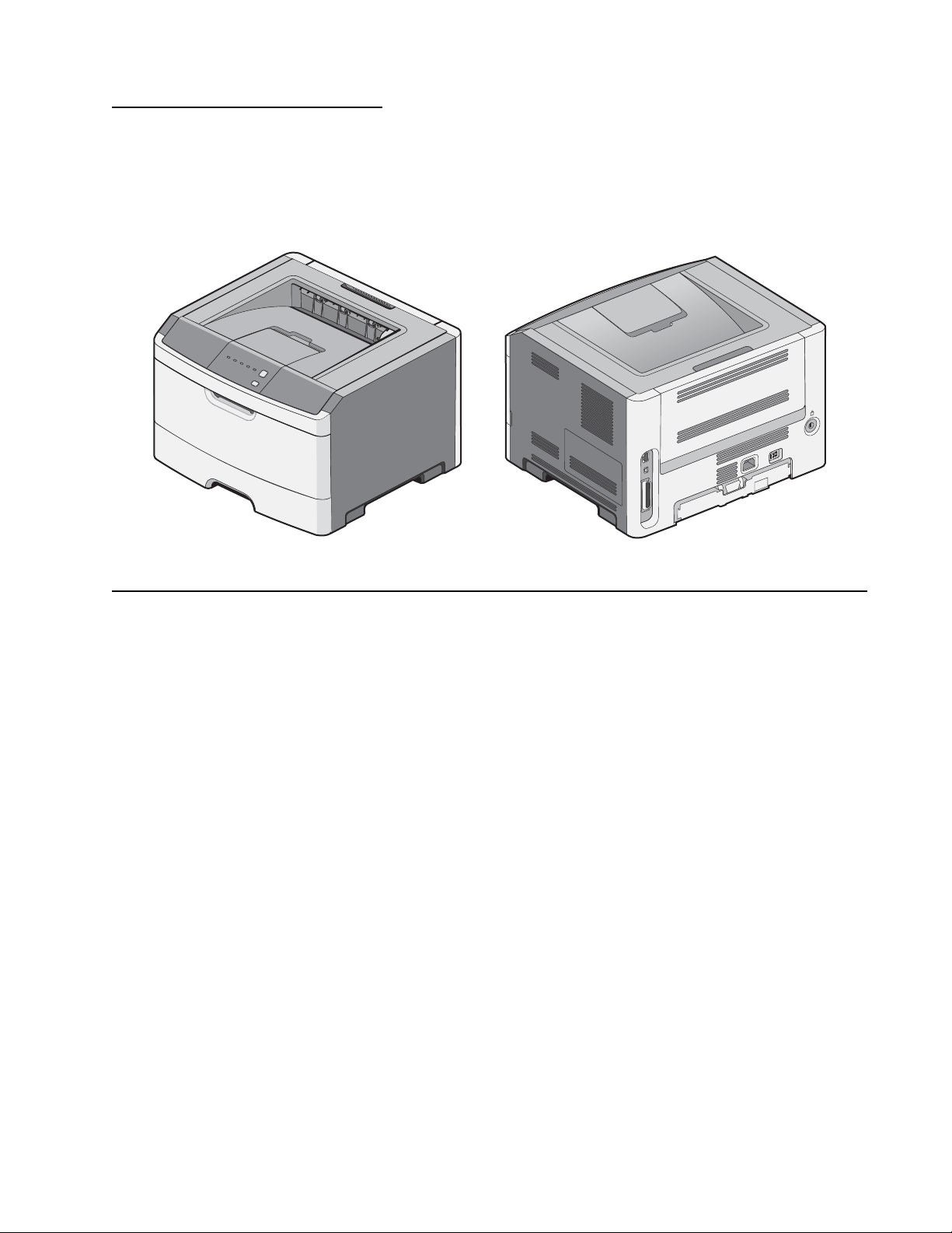
Locations and connections. . . . . . . . . . . . . . . . . . . . . . . . . . . . . . . . . . . . . . . . . . . . . . . . . . . . . . . . . . . . 5-1
Locations . . . . . . . . . . . . . . . . . . . . . . . . . . . . . . . . . . . . . . . . . . . . . . . . . . . . . . . . . . . . . . . . . . . . . . . . . . .5-1
Front view . . . . . . . . . . . . . . . . . . . . . . . . . . . . . . . . . . . . . . . . . . . . . . . . . . . . . . . . . . . . . . . . . . . . . .5-1
Rear view . . . . . . . . . . . . . . . . . . . . . . . . . . . . . . . . . . . . . . . . . . . . . . . . . . . . . . . . . . . . . . . . . . . . . . .5-1
iv Lexmark™ E260, E260d, E260dn
Page 5

4513-200, -220, -230
Controller board connector pin values . . . . . . . . . . . . . . . . . . . . . . . . . . . . . . . . . . . . . . . . . . . . . . 5-2
Preventive mainte nan ce. . . . . . . . . . . . . . . . . . . . . . . . . . . . . . . . . . . . . . . . . . . . . . . . . . . . . . . . . . . . . . . . 6-1
Safety inspect ion guide . . . . . . . . . . . . . . . . . . . . . . . . . . . . . . . . . . . . . . . . . . . . . . . . . . . . . . . . . . . . . . . 6-1
Lubrication spec if ications . . . . . . . . . . . . . . . . . . . . . . . . . . . . . . . . . . . . . . . . . . . . . . . . . . . . . . . . . . . . . 6-1
Parts catalog . . . . . . . . . . . . . . . . . . . . . . . . . . . . . . . . . . . . . . . . . . . . . . . . . . . . . . . . . . . . . . . . . . . . . . . . . . . . 7-1
How to use this parts catalog . . . . . . . . . . . . . . . . . . . . . . . . . . . . . . . . . . . . . . . . . . . . . . . . . . . . . . . . . . 7-1
Index . . . . . . . . . . . . . . . . . . . . . . . . . . . . . . . . . . . . . . . . . . . . . . . . . . . . . . . . . . . . . . . . I-1
Part number index. . . . . . . . . . . . . . . . . . . . . . . . . . . . . . . . . . . . . . . . . . . . . . . . . . . . . I-3
Table of Contents v
Page 6

4513-200, -220, -230
vi Lexmark™ E260, E260d, E260dn
Page 7

4513-200, -220, -230
Notices and safety information
The followi ng laser notice labels may be affixed to this printer.
Laser no tice
The printer is certified in the U.S. to con for m to the requi rements of DHHS 21 CFR Subchapter J for Clas s I (1)
laser products, and elsewhere is certified as a Class I laser product conforming to the requirements of IEC
60825-1.
Class I laser products are not considered to be hazardous. The printer contains internall y a Class IIIb (3b) laser
that is nomin all y a 7 milliwatt gallium arsenide laser operating in t he wavelength region of 655-675 nanometers.
The laser system and printer are desi gned so there is never any huma n access to laser radiati on above a Class
I level during normal operation, user maintenance, or prescribed service condition.
Laser
Der Drucker erfüllt gemäß amt li cher Bestätigung der USA die Anforderungen der Bestimmung DHHS
(Department of Health and Human Services) 21 CFR Tei l J für Laserprodukte der Klasse I (1). In anderen
Ländern gilt der Drucker als Laserprodukt der Klasse I, der die Anforderungen der IEC (International
Electrotechnical Commission) 60825-1 gemäß amtlicher Bestätigung erfüllt.
Laserprodukte der Klasse I gelten als unschädlich. Im Inneren des Druckers befindet sich ei n Laser der Klasse
IIIb (3b), bei dem es sich um einen Galliumarsenlaser mit 7 Milliwatt handelt, der Wellen der Länge 655-675
Nanometer ausstr ahlt. Das Lasersystem und der Drucker sind so konzipiert, daß im Norma lbetrieb, bei der
Wartung durch den Benutzer oder bei ordnungsgemäßer Wartung durch den Kundendienst Laserbestrahlung,
die Klasse I übersteigen würde, Menschen keinesfalls erreicht.
Avis relatif à l’utilisation de laser
Pour les Etats-Unis: cette imprimante est ce rt if iée conforme aux provisions DHHS 21 CFR alinéa J concerna nt
les produits laser de Classe I (1). Pour l es autres pays : cette imprimante répond aux normes IEC 6082 5-1
relatives aux produits laser de Classe I.
Les produits laser de Classe I sont considérés comme des produits non dangereux. Cette imprimante est
équipée d’un l aser de Classe IIIb (3b) (arséniur e de gallium d’une puissance nominal e de 7 milliwatts) émettant
sur des longueurs d’onde comprises entre 655 et 675 nanomètres. L’imprimante et son système laser sont
conçus pour impossible, dans des conditions normales d’utilisation, d’entretien par l’utilisateur ou de révision,
l’exposition à des rayonnements laser supérieurs à des rayonnements de Classe I .
Avvertenze sui prodotti laser
Questa stampant e è certificata negli Stati Unit i per essere conforme ai requisiti del DHHS 21 CFR Sottocapitolo
J per i prodotti laser di classe 1 ed è certi fi cata negli altri Paesi come prodotto laser di classe 1 conforme ai
requisiti del la norma CEI 60825-1 .
I prodotti laser di classe non sono consider at i pericol osi. La st ampant e contie ne al suo interno un laser d i classe
IIIb (3b) all’arseniuro di gallio della potenza di 7mW che opera sulla lunghezza d’onda compresa tra 655 e 675
nanometri. Il sistema laser e la stampante sono stati proget tati in modo tale che le persone a contatto con la
stampante, durante il normale funzionamento, le operazioni di servizio o quelle di assistenza tecnica, non
ricevano radi azioni laser superiori al livell o della classe 1.
Notices and safet y information vii
Page 8

4513-200, -220, -230
Avisos sobre el láser
Se certifica que, en los EE.UU., esta impresora cumple los requisitos para los productos láser de Clase I (1)
establecidos en el su bcapítulo J de la norma CFR 21 del DHHS (Departamento de Sanidad y Servicios) y, en
los demás países, reúne todas las condiciones expuestas en la norma IEC 60825-1 para productos láser de
Clase I (1).
Los productos láser de Clase I no se consi deran peligrosos. La impresora contiene en su interior un láser de
Clase IIIb (3b) de arseniuro de gali o de funcionamiento nominal a 7 milivatios en una lo ngitud de onda de 655 a
675 nanómetr os. El sistema láser y la impresora están diseñados de forma que ninguna persona pueda verse
afectada por ni ngún ti po de radiación láser superior al nivel de la Clase I dur ante su uso normal, el
mantenimiento realizado por el usuario o cual quier otra situación de servicio técnic o.
Declaração sobre Laser
A impressora e stá cer tific ada n os E.U.A . em conf ormidade com os r equisi tos da regu lamentaç ão DHHS 21 CFR
Subcapítulo J para a Clas se I (1) de produt os laser . Em outr os locai s, est á cer tific ada co mo um produ to laser da
Classe I, em conformidade com os requisitos da norma IEC 60825-1.
Os produtos lase r da Class e I não são cons id erados per igosos . Inte rnamen te, a impress ora contém um produ to
laser da Classe IIIb (3b), design ado laser de arseneto de potássio, de 7 milliwatts , operando numa faixa de
comprimento de onda entre 655 e 675 nanómetros. O sistema e a impressora laser foram concebidos de forma
a nunca existir qualquer possiblidade de acesso humano a radiaç ão laser superior a um nível de Classe I
durante a operação nor m al, a manutenção f eita pelo utilizador ou condições de assistência prescritas.
Laserinformatie
De printer voldoe t aan de ei sen di e ges teld worden aan een laser pro dukt va n klass e I . Voor de Verenigd e Stat en
zijn deze eisen vastgelegd in DHHS 21 CFR Subchapter J, voor andere land en in I E C 60825-1.
Laserprodukten van klasse I worden niet al s ongevaarlijk aangemerkt. De printer i s voorzien van een laser van
klasse IIIb (3b), dat wil zeggen een gal lium arsenide-laser van 7 milliwatt met een golflengte van 655-675
nanometer. Het laser gedee lte en de print er zijn zo ontworp en dat bij normaal gebr uik, bi j onder houd of repar atie
conform de voorschriften, nooit blootstelli ng mo gelijk is aan las erstraling boven een niveau zoals
voorgeschr even is voor kl asse 1.
Lasermeddelelse
Printeren er godkendt som et Klasse I-laserprodukt, i overenstemmelse med kravene i IEC 60825-1.
Klasse I-l aserprodukter betragtes ikke som farlige. Printeren indeholder internt en Klasse IIIB (3b)-laser, der
nominelt er en 7 milli watt galliumarsenid laser, som arbejder på bølgelængdeområdet 655-675 nanometer.
Lasersystemet og printeren er udformet således, at m ennesker aldrig udsæ ttes for en laserstråling over Klasse
I-niveau ved nor m al dr ift, brugervedligeholdelse eller obligatoriske servicebetingelser.
viii Lexmark™ E260, E260d, E260dn
Page 9

4513-200, -220, -230
Laserilmoitus
Tämä tulostin on sertif ioitu Yhdysvalloissa DHHS 21 CFR Subchapter J -standardin mukaiseksi luokan I (1) lasertuot teeksi ja muualla IEC 60825-1 -standardin mukai seksi luokan I lasertuotteeksi.
Luokan I laser tuot teit a ei pi detä hai tall isi na. Tul ostimen sisäl l ä on luok an III b (3b) laser, joka o n ni mellist eholt aan
7 mW:n galliumarsenidilaser ja toimii 655 - 675 nanometrin aallonpituuksilla. Laserjärjestelmä ja tulostin ovat
rakenteelt aan sellaisia, että käyttäjä ei joudu al tt iiksi luokkaa 1 suuremmalle säteilylle normaalin käytön,
ylläpidon tai huollon aikana.
Huomautu s las er laitteesta
Tämä kirjoi tin on Yh dysval loiss a luokan I (1) las erlai ttei den DHHS 21 CFR Subc hapt er J -määr ity ksen mukai nen
ja muualla luokan I laserlaitteiden IEC 60825-1 -määri tyksen mukainen.
Luokan I laserlaitteiden ei katsota olevan vaarallisia käytt äjälle. Kirjoittimessa on sisäinen luokan IIIb (3b) 7
milliwatin gal liumarsenidilaser, joka toi mii aaltoalueella 655 - 675 nanometriä. Laserjärjestelmä ja kirjoitin on
suunniteltu siten, että käyttäjä ei altistu lu okan I määrityk siä voimakkaamm alle säteilylle kirjoitt imen normaalin
toiminnan, käyttäjän tekemien huoltotoimien tai muiden huoltotoimien yhteydessä.
VARO! Avattaessa ja suojalukitus ohitettaessa olet alttiina näkymättömälle lasersäteilylle. Älä katso
säteeseen.
VARNING! Osynlig laserst rålning när denna del är öppnad och spärren är urkopplad. Betrakta ej strålen.
Laser-notis
Denna skrivar e är i USA certifierad att motsvara kraven i DHHS 21 CFR, underparagraf J för laserprodukter av
Klass I (1). I andra länder uppfyller skrivaren kraven för laserprodukter av Kl ass I enligt kraven i IEC 60825-1.
Laserprodukter i Klass I anses ej hälsovådli ga. Skrivaren har en inbyggd laser av Klass IIIb (3 b) som består av
en laserenhet av gal lium-arsenid på 7 milliwatt som arbetar i våglängdsomr ådet 655-675 nanometer.
Lasersystem et och skrivaren är utforma de så att det aldrig finns risk för att någon perso n u tsätts för
laserstrå lning över Klass I-nivå vid normal användni ng, underhål l som utförs av användaren eller annan
föreskriv en serviceåtgärd.
Laser-melding
Skriveren er godkjent i USA etter kravene i DHHS 21 CFR, underkapittel J, for klasse I (1) laserprodukter, og er
i andre land godkjent som et Klasse I-laserprodukt i samsvar med kravene i IEC 60825-1.
Klasse I-laserprodukter er ikke å betrakte som farli ge. Skriveren inneholder internt en klasse IIIb (3b)-laser, som
består av en gallium-arsenlaserenhet som avgir stråling i bølgelengdeområdet 655-675 nanometer.
Lasersystem et og skrive ren er utformet slik at personer aldri utsett es for la serstrål i ng ut over klasse I-n ivå under
vanlig bruk, vedlikehold som utføres av brukeren, ell er fo reskrevne serviceoperasjoner.
Notices and safety information ix
Page 10
4513-200, -220, -230
Avís sobre el Làser
Segons ha estat cert ificat als Estats Units, aquesta impressor a compleix els requi sits de DHHS 21 CFR, apartat
J, pels productes làser de classe I (1), i segons ha est at certificat en altres llocs, és un producte làser de cla sse
I que compleix els requisits d’IEC 60825-1.
Els productes l àser de classe I no es consideren perillosos. Aquesta impressora conté un làser de classe IIIb
(3b) d’arseniür de gal.li, nominalment de 7 mil.liwats, i funciona a la regió de lon gitud d’ona de 655-675
nanòmetres. El sistema làser i la impressora han sigut concebuts de manera que mai hi hag i exposició a la
radiació làser per sobre d’u n nivell de classe I durant una operació normal, durant les tasques de manteniment
d’usuari ni durant els serveis que satisfacin les condicions prescrites.
x Lexmark™ E260, E260d, E260dn
Page 11
4513-200, -220, -230
Notices and safety information xi
Page 12

4513-200, -220, -230
xii Lexmark™ E260, E260d, E260dn
Page 13
4513-200, -220, -230
Safety information
• The safety of this product is based on test ing and approvals of the original design and specific
components. The man ufacturer is not responsible for safety in the event of use of unauthorized
replacement parts.
• The maintenance inf ormation fo r this product has been prepared for use by a professional service person
and is not intended to be used by others.
• There may be an increased risk of electric shock and personal injury during disassembly and servicing of
this product. Professional servi ce personnel should understand this and take necessary precautions.
• CAUTION: When you see this symbol, there i s a danger from hazardous volta ge i n the area of the
product where you a re work ing. Unp lug th e product be fore y ou begin, or us e cau tion i f th e product
must receive power in order to perform th e task.
Consignes de sécurité
• La sécurité de ce pro duit repose sur des tests et des
agréations por tant sur sa conception d'origine et sur des com posants particuliers. Le fabricant n'assume
aucune respon sabilité concernant la sécurité en cas d'ut ilisation de pièces de rechange non agréées.
• Les consignes d'entretien et de réparati on de ce produit s'adressent uniquement à un personnel de
maintenance qualifié.
• Le démontage et l'entretien de ce produit pouvant présenter certains risques électriques, le personnel
d'entretien qualifié devra prendre toutes les précautions néce ssaires.
• ATTENTION : Ce symbole indique la présence d'une tension dangereuse dans la partie du
produit sur laquelle vous travaillez. Débranchez le produit avant de commencer ou faites preuve
de vigilance si l' exécution de la tâche exige que le produit reste sous tensio n.
Norme di sicurezza
• La sicurezza del prodotto si basa sui test e sull'approvazione del progetto originale e dei componenti
specifici. Il produttor e non è responsabile per la sicurezza in caso di sostituzione non autorizzata dell e
parti.
• Le informazion i riguardanti la manutenzione di questo prodotto sono indirizzate soltanto al personale di
assistenza autorizzato.
• Durante lo smontaggio e la manutenzi one di questo prodo tto,
il rischio di subire scosse elettriche e danni alla persona è più elevato. Il personale di assistenza
autorizzat o deve, quindi, adottare le precauzioni necessarie.
• ATTENZIONE: Questo simbolo indi ca la presenza di tensione pericolosa nell'ar ea del prodotto.
Scollegare il pr odotto prima di iniziare o usare cautela se il prodotto deve essere alimentato per
eseguire l'intervento.
Sicherheitshinweise
• Die Sicherheit di eses Produkts bas iert auf Tests und Zul assungen des ursprünglichen Modells und
bestimmter Baut eil e. Bei Verwendung nicht genehmigter Ersatzteile wird vom Hersteller keine
Verantwortung oder Haftung für die Sicherheit übernommen.
• Die Wartungsinformationen für dieses Produk t si nd ausschließlich für die Verwendung durch einen
Wartungsfachmann bestimmt.
• Während des Auseinandernehmens und der Wartung des Geräts besteht ein zusätzliches Risiko eines
elektrischen Schlags und körperlicher Verletzung. Das zuständige Fachpersonal sollte entsprechende
Vorsichtsmaßnahmen treffen.
Safety in fo rmation xiii
Page 14
4513-200, -220, -230
• ACHTUNG: Dieses Symbol weist auf eine gefährliche elektrische Spannung hin, die i n diesem
Bereich des Produkts auf tret en kann. Zieh en Sie vor den Arbeit en am Gerät den Netzsteck er des
Geräts, bzw. arbeiten Sie mit großer Vorsi cht, wenn das Produkt für die Ausführung der Arbeiten
an den Strom angeschlossen sein muß.
Pautas de Seguridad
• La seguridad de este producto se basa en pruebas y aprobaciones del diseño original y componentes
específico s. El fabri cante no es responsable de la seguridad en caso de uso de pi ezas de repuesto no
autorizadas.
• La información sobre el mantenimiento de este producto está dirigida excl usivamente al personal
cualificado de mantenimiento.
• Existe mayor riesgo de de scarga e léc trica y de dañ os pe rsonal es du rante e l desmont aj e y la r eparaci ón de
la máquina. El personal cualificado debe ser consciente de este peligro y tomar las precauciones
necesarias.
• PRECAUCIÓN: este símbolo indica que el voltaje de la parte del equipo con la que está
trabajando es peligroso. Antes de empezar, desenchufe el equipo otenga cuidado si, para
trabajar con él, debe conectarlo.
Inform a çõ es de Segurança
• A segurança deste produto baseia-se em testes e aprovações do modelo original e de compon entes
específico s. O fabr icante não é responsável pela segunrança, no caso de uso de peças de substituição
não autorizadas.
• As informações de segurança relativas a este produto destinam-se a profissionais destes serviç os e não
devem ser utilizadas por outras pessoas.
• Risco de choques eléctricos e ferimentos graves durante a desmontagem e manutenção deste produto.
Os profissi onais destes serviços devem estar avisados deste facto e tomar os cuidados necessários.
• CUIDADO: Quando vir este símbolo, existe a possível presença de uma potencial tensão
perigosa na zona do produto em que está a trabalhar. Antes de começar, desligue o produto da
tomada eléctr ica ou seja cu ida doso caso o pr oduto t enha de estar liga do à c orrent e eléc tric a para
realizar a taref a necessária.
xiv Lexmark™ E260, E260d, E260dn
Page 15
4513-200, -220, -230
Informació de Seguretat
• La seguretat d'aquest producte es basa en l'avaluació i aprov ació del disseny original i els components
específics .
El fabricant no es fa responsable de les qüestions de
seguretat si s'u ti litzen peces de recanvi no autoritzades.
• La informació pel ma nteniment d’aquest producte està orient ada exclusivament a professionals i no està
destinada
a ningú que no ho sigui.
• El risc de xoc elèctric i de danys personals pot augmentar durant el procés de desmuntatge i de servei
d’aquest producte. El personal professional ha d’estar-ne assabentat i prend re
les mesures con venients.
• PRECAUCIÓ: aquest símbol indica que el voltatge de la par t de l 'equip amb la qual esteu
treballan t és perill ós. Abans de començ ar, desendol leu l' equip oextremeu les precaucion s si, per
treballar am b l'equip, l'heu de connectar.
Safety information xv
Page 16
4513-200, -220, -230
CAUTION
A caution identifies something that might cause a servicer har m.
CAUTION
This type of caution i ndicates there is a danger from hazardous volta ge in t he area of the
product where you are working. Unplug the product before you begi n, or use caution if the
product must recei ve power in order to perform the task.
Preface
This manual contains maintenance procedures for service personnel. It is divided into the following chapt ers:
1. General infor m a ti o n contains a general description of the printer and the maintenance approach used to
repair it. Speci al tools and test equipment, as well as general environmental and safety instr uctions, are
discussed.
2. Diagnostic information contains an error indicator table, sym ptom tables, and service checks used to
isolate failing field replaceable units (FRUs).
3. Diagnostic aids contains tests and checks used to locate or repeat symptoms of printer problems.
4. Repair infor ma t io n provides instructions for making printer adjustments and removing and i nstalling
FRUs.
5. Connector locati ons uses illustrations to identify the connector locations and test points on the printer.
6. Preventive maintenance contains the lubrication specifications and recom me ndations to prevent
problems.
7. Part s catalog contains illust rations and part numbers for individual FRUs.
Change history
Revision date Updates
2015/08/18 Parts catalog (Assembly 3: Frame)—Added PN 40X0016.
2012/08/08 Changed all cross-references that call for the left side cover removal procedures.
2011/10/28 Added this warning: “Warni ng: Do not strip th e insulation off the red and black wires. The
2011/9/14 Revised the media feed clutch assembly removal procedure in “Media feed clutch
Conventions
Note: A note provides additional information.
Warning: A warning identi fi es something th at might damage the product hardware or software.
There are several types of caution statements:
connectors wil l not work if t he insulation is removed,” in step 8 of “Media feed clutch
removal” on page 4-38.
removal” on page 4-38.
xvi Lexmark™ E260, E260d, E260dn
Page 17
4513-200, -220, -230
CAUTION
This type of caution i ndicates a hot surface.
CAUTION
This type of caution i ndicates a tipping hazard.
Conventions xvii
Page 18

4513-200, -220, -230
xviii Lexmark™ E260, E260d, E260dn
Page 19
4513-200, -220, -230
1. General in formation
The Lexmark™ E260, E260d, and E260dn are monochrome laser printers designed for single users or small
workgroups. This book contains inf ormation on E260, E260d and E260dn. For information on E360d and
E360dn, see the 4513-42 0,-430 service manual. For information on E460dn and E460dw, see the 4513-630, 63W, -6EW se rvice manual.
Maintenance approach
The diagnostic information in this manual leads to th e correct field replaceable unit (FRU) or part. Use the er ror
code charts, sympt om index, and service checks to determine the symptom and repair the fai lure. See
“Diagnostics i nformation” on page 2-1 for more information. See “Repair information” on page 4-1 to help
identify parts. After completing the repair, perform tests as needed to verify the repair.
General information 1-1
Page 20
4513-200, -220, -230
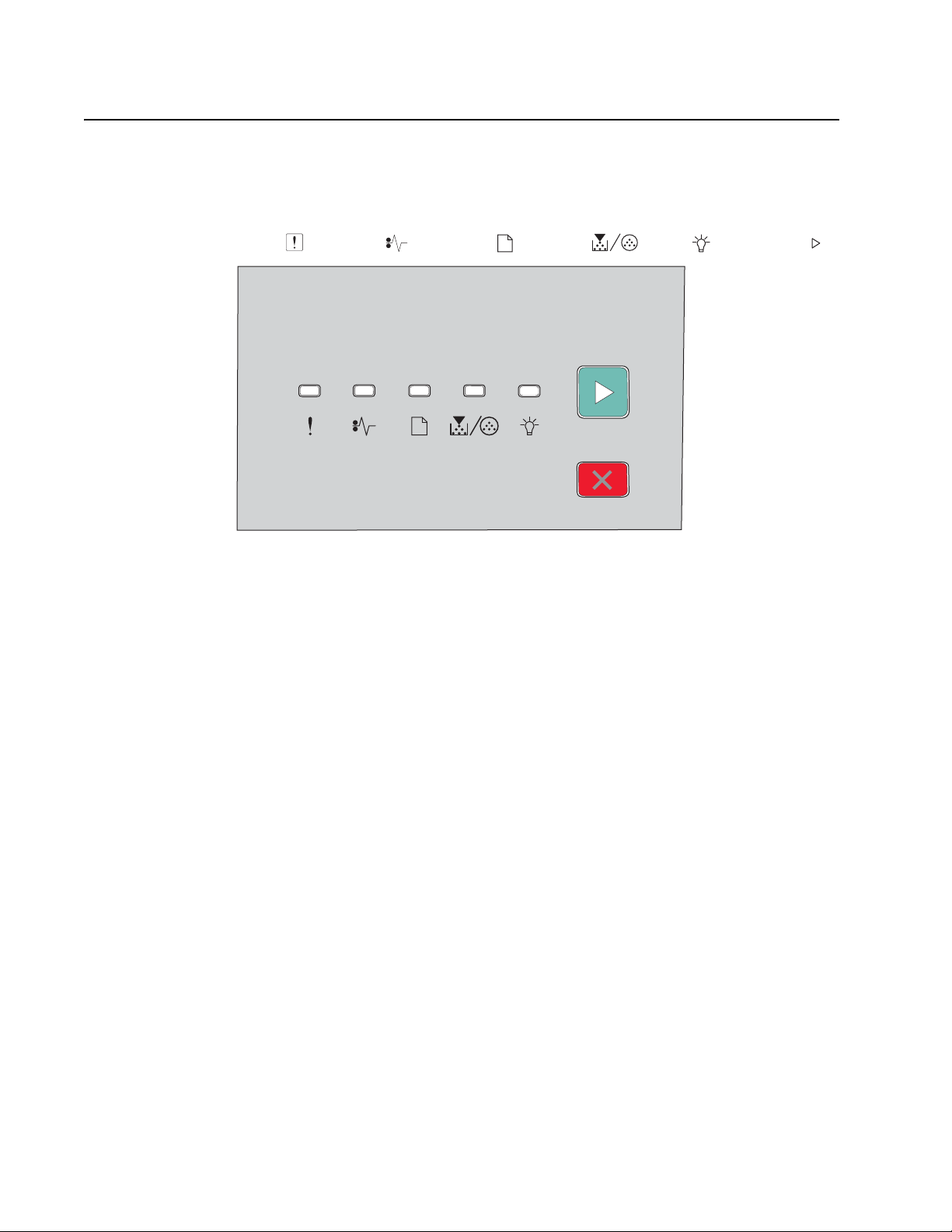
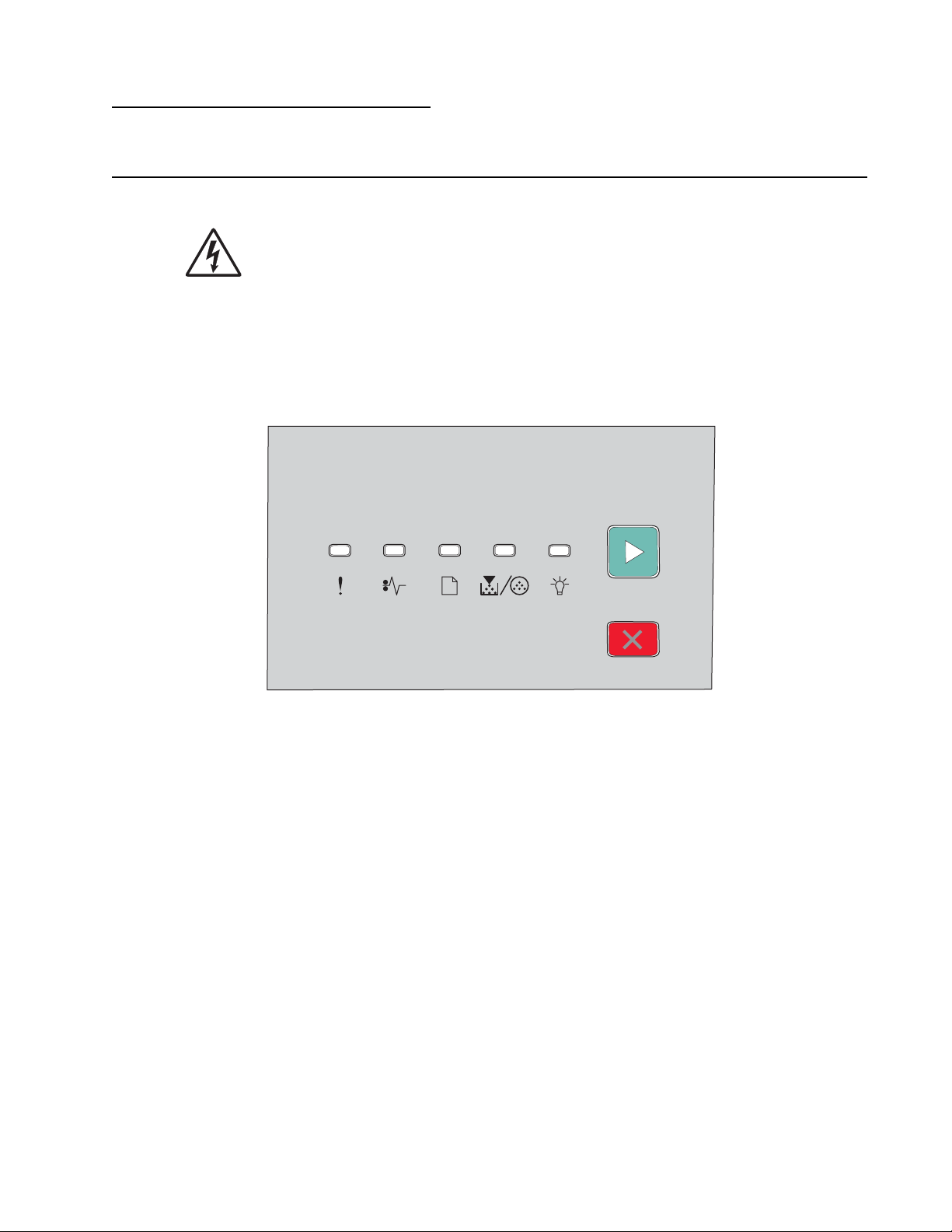
Overview of the operator panel
The operator panel consists of these items:
• LED operator panel
• Two buttons: Cancel and Continue
• Six lights: Error , Paper Jam , Load Paper , Toner Low , Ready , and Continue
1-2 Lexmark™ E260, E260d, E260d n
Page 21
4513-200, -220, -230
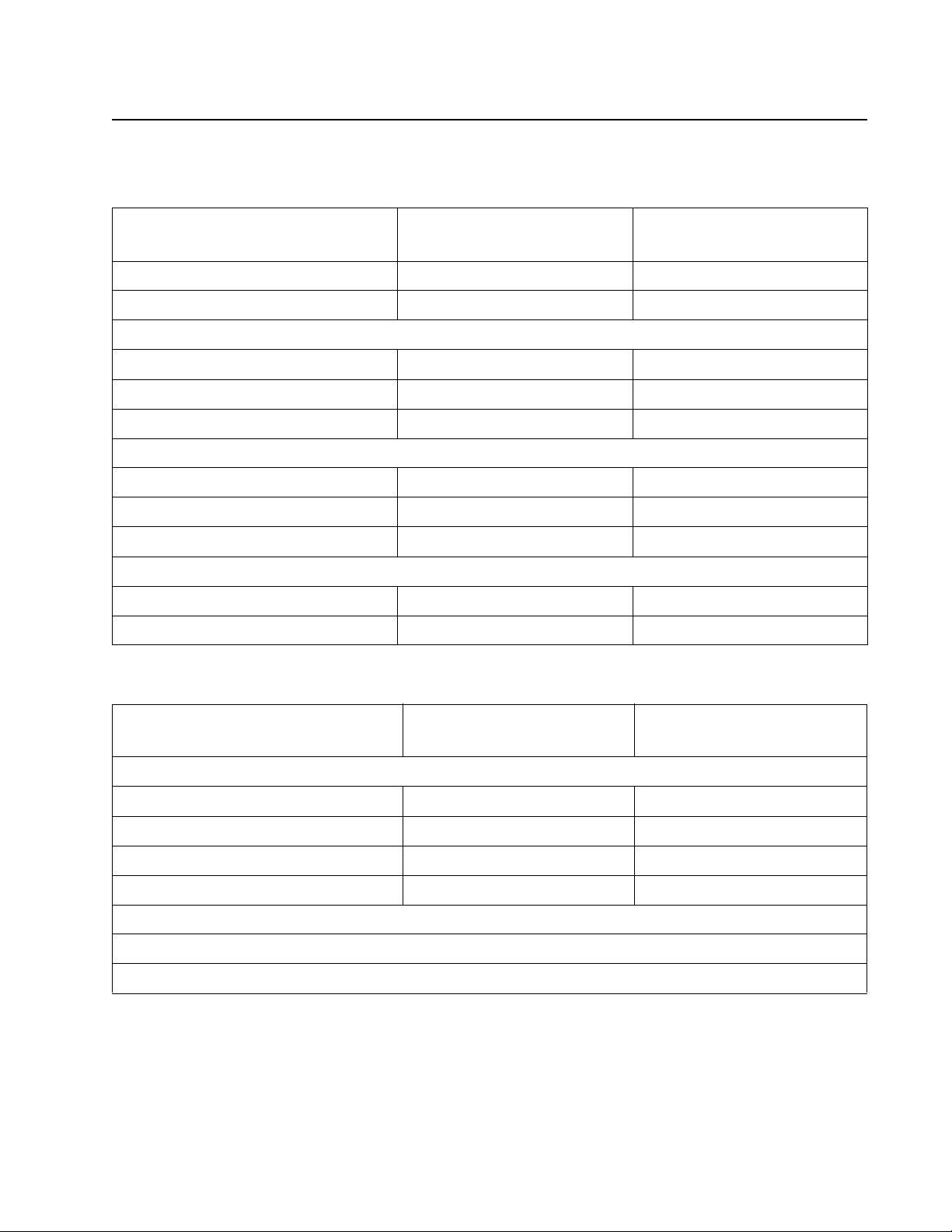
Specifications
Memory
Item
Standard memory 32MB 32MB
Maximum memory 160MB 160MB
Optional memory
128MB ✔✔
256MB xx
512MB xx
Optional flash memory
64MB xx
256MB xx
Optional font cards (DBCS) ✔✔
Option slots
Memory slots 1 1
Flash memory/option card xx
4513-200, -220
Lexmark E260, E260d
4513-230
Lexmark E260dn
Print quality setti ngs
Item
Print resolution
1200 Image qualit y¹ ✔✔
2400 Image qualit y² ✔✔
600 X 600 dpi ✔✔
1200 X 1200 dpi³ ✔✔
¹ 1200 Image quality is def ined as 600 dpi with 2 bit IET (Image Technology) default mo de for all models.
² 2400 Image quality is def ined as 600 dpi with 4 bit IET.
³ True 1200 dpi at 1/2 the rated speed
4513-200, -220
Lexmark E260, E260d
4513-230
Lexmark E260dn
General information 1-3
Page 22

4513-200, -220, -230
Connectivity and compatibility
Item
Data stream emulation s
Host based printing ✔✔
PCL 5e and PCL 6 ✔✔
PostScript 3 ✔✔
PPDS migration tool ✔✔
PDF v1.6 xx
XPS¹ xx
HTML (including DBCS) xx
Directimage xx
Compatibility Windows/Macintosh/ Linux Windows/Macintosh/ Linux
Standard local connec ti ons
Parallel ✔✔
USB* ✔✔
Standard network connect ions
4513-200, -220
Lexmark E260, E260d
4513-230
Lexmark E260dn
Ethernet (10/100 Base Tx) x ✔
Wireless ethernet 802.11b/g/n xx
Optional local connections
Optional network connections:
external print server support
*All models are USB 2.0 Certified devices supporting Hi-Speed data transfer.
¹ Includes the HD photo image format
² Includes support for the following graphics formats: TIFF, TIF, JPG, GIF, PNG, BMP, PCX, AND DCX
✔✔
1-4 Lexmark™ E260, E260d, E260d n
Page 23

4513-200, -220, -230
Media trays and supply capacity
Item
Available input trays
Integrated 250-sheet tr ay ✔✔
50-sheet MP feeder xx
1-sheet manual feed slot ✔✔
Optional input sources
250-sheet drawer ✔✔
550-sheet drawer ✔✔
Manual/integrated print duplex Integrated I ntegrated
Envelope conditioning x x
Available out put trays
4513-200, -220
Lexmark E260, E260d
4513-230
Lexmark E260dn
Standard 150-sheet sensing bin ✔✔
Toner and photoconductor
Toner cartr idge 1,000 standard pages SWE¹
3,500 standard pages
High toner cartri dge xx
Photoconductor kit Up to 30,000 ² Up to 30,000 ²
¹ Declared value in accordance with ISO/IEC 19752
² Up to 30,000 pages, based on an average of 3 pages per job and approximately 5% coverage per page. Yields may
vary based on customer usage.
1,000 standard pages SWE¹
3,500 standard pages
General information 1-5
Page 24

4513-200, -220, -230
Types of print media
Note: Ensure trays are properly loaded. Never mix media types within a tray.
Source Sizes Types Weight Input capacity* (sheets)
Input tray 1
(250-sheet tray)
2nd Drawer option
(250/550-sheet
drawer)
Manual feed input A4, A5, A6, JIS¹-B5,
A4, A5, A6,J IS¹-B5,
letter, legal , executive,
oficio (Mexico)², folio²,
statement
A4, A5, JIS¹ -B5, letter,
legal, executive, oficio
(Mexico )², folio²,
statement
letter, legal , executive,
folio, oficio, statement,
Universal
Plain paper,
recycled, l abels,
bond, lett erhead,
preprinted , colored
paper, light paper,
heavy paper,
rough/cotton,
custom type [x]
Plain paper,
recycled, l abels,
bond, lett erhead,
preprinted , colored
paper, light paper,
heavy paper,
rough/cotton,
custom type [x]
Plain paper,
transparency,
bond, lett erhead,
preprinted , colored
paper, light paper,
heavy paper,
rough/cotton,
custom type [x]
Card stock*** • 120–163 g/m²
60–90 g/m²
(16–24 lb)
60–90 g/m²
(16–24 lb)
60–163 g/m²
(16–43 lb)
(16–43 lb)
Index Bristol
• 75–163 g/m²
(46–100 lb)
Tag
• 250 paper
• 50 labels**
• 250 paper
• 550 paper
• 50 labels**
1 (all medias)
1
7 ¾, 9, 10, DL, C5, B5,
other
Duplex A4, lett er, le g al , of ic io
(Mexico )², folio²
* Capacity for 20 lb print media, unless otherwise noted.
** Use for occasional printing onl y.
*** Grain short is recommended. Use rear exit for best results.
¹Japanese Indust ry Standard
² If a source supports size sensing and is act ivated, then neither the “oficio” value nor the “folio” value appears in that
source’s list of supported media sizes. These values only appear in a source’s list of supported media sizes either when
the source is non- size sensing or when the source’s size sensing har dware is deactivated and then the device is power
cycled.
Envelopes
Rough envelopes
Plain paper,
recycled, bond,
letterhead,
preprinted , colored
paper, light paper,
heavy paper,
custom type [x]
75 g/m² (20 lb) 1
60–90 g/m²
(16–24 lb)
1-6 Lexmark™ E260, E260d, E260d n
Page 25
4513-200, -220, -230
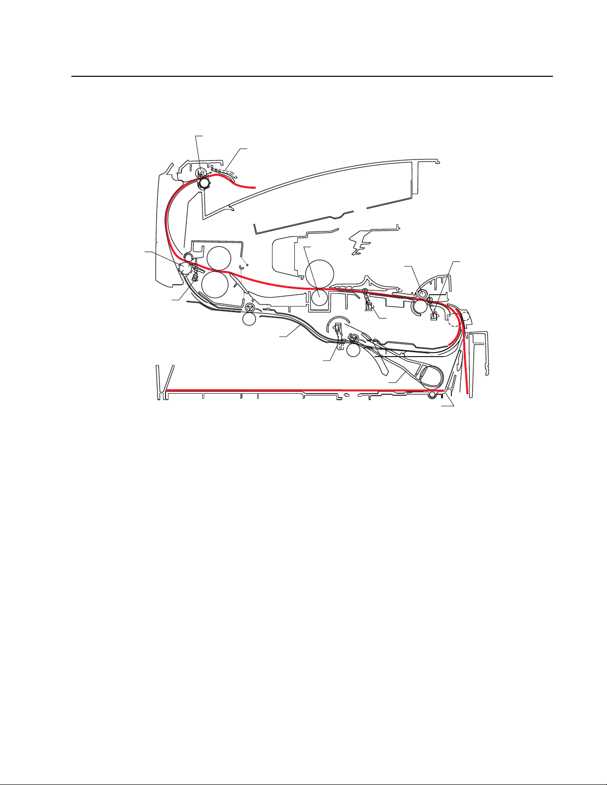
G
H
K
L
D
M
A
B
C
E
F
J
I
Tips on preventing jams
Paper path
A Paper path A-B 125.3 mm
B Manual feed sensor B-C 9.0 mm
C Upper end feed rol ls C-D 59.8 mm
D Input sensor D-E 44.9 mm
E Transfer roll E-F 112.7 mm
F Fuser F-G 21.4 mm
G Fuser exit rolls G-H 114.8 mm
H Fuser exit sensor H-I 7.5 mm
I Exit rolls I-J 17.0 mm
J Exit sensor I-K 211.7 mm
K Duplex unit K-L 93.4 mm
L Duplex sensor L-M 8.4 mm
M Auto compensat or
General information 1-7
Page 26
4513-200, -220, -230
Most paper jams can be avoided by correctly loading paper and specialty media in the printer.
The followi ng hints can help prevent paper jams:
• Use only the recommended print media.
• Do not overload th e print med ia sourc es. Mak e sure the st ack heig ht does not exceed the maximu m height
indicated by t he stack line on the labels in the sources.
• Do not load wrinkled, creased, damp, or curled print media.
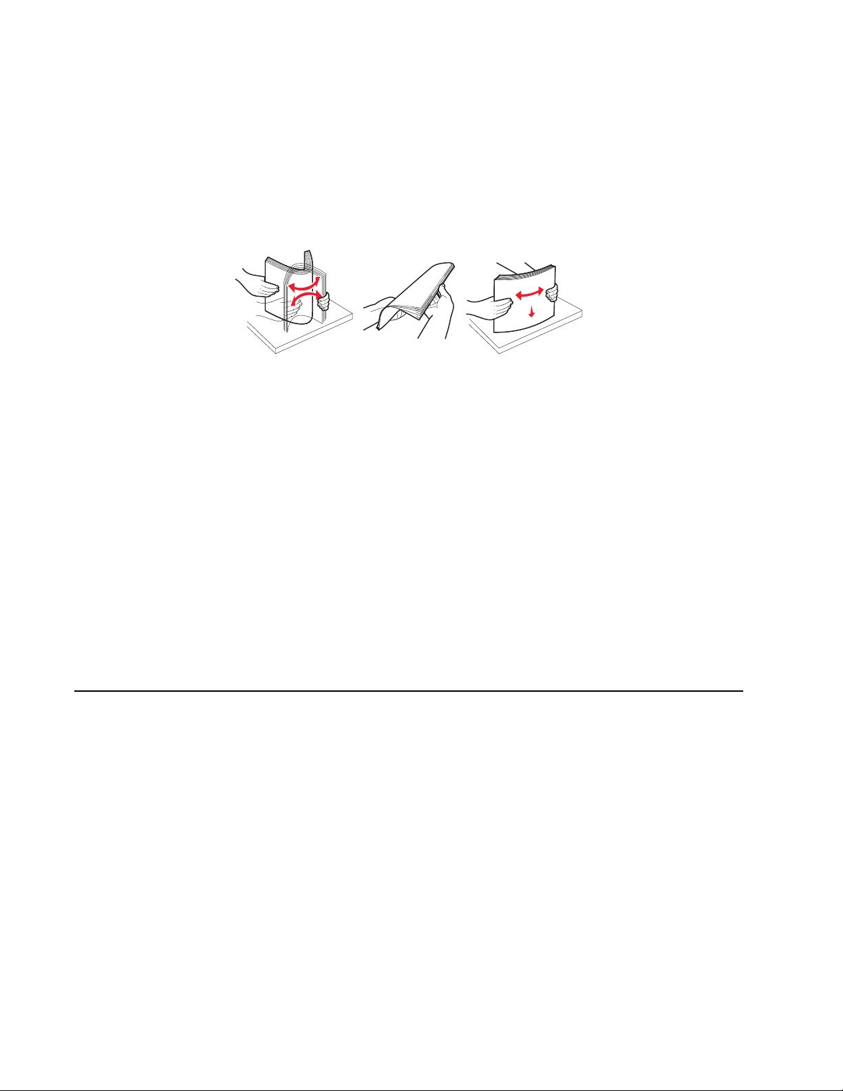
• Flex, fan, and s tr aighte n print m edia bef ore l oading i t. I f jams do occu r with the print medi a, then try f eeding
one sheet at a time through the manual feeder.
• Do not mix print media sizes, weights, or types in the same print media source.
• Push all trays in firmly after loading them.
Note: Make sure the media stack is below the maximum media fil l i ndicators on the 250-sheet tray before
pushing the tray into the printer.
• Make sure paper guides are posit ioned before loading the paper or specialty media.
• Do not remove trays while a job is printing.
• Before loadi ng transparencies, fan the stack to prevent sheets from sticking together.
• Do not use envelopes tha t:
– Have excessive curl
– Are stuck together
– Are damaged i n any way
– Contain windows, holes, perforations, cutouts , or embossments
– Have metal clasps, string ties, or metal folding bars
– Have post age stamps attached
– Have any expos ed adhesive when the flap is in the sealed position
• Use only recommended m edia. Refer to the Card Stock & Label Gui de available on the Lexmark Web site
at www.lexmark. com for more informati on about which media provides optimum results for the current
printing envir onm ent.
Tools
The removal and adjust m ent procedure s require the following tools and equipment:
• Spring hook
• Needle nose pliers
• Volt-ohmmeter
• #1 and #2 Phillips screwdr iv e r
• Slotted screwdriver
1-8 Lexmark™ E260, E260d, E260d n
Page 27

4513-200, -220, -230
Acronyms
ACM Autocompensator Mechanism (or paper feed)
ADC Analog-to-digital Converter
ASIC Application Specific Integrated Circuit
CBM Complete Bill Of Material
DEV Development Roll (of print cartridge/photoconductor
DIMM Dual In-Line Memory Module
ENA External Network Adapter
FRU Field Replaceable Unit
HBP Host Based Printing
HVPS High Voltage Power Supply
LCD Liquid Crystal Dio de
LED Light Emitting Diode
LSU Laser Scanning Unit
LVPS Low Voltage Power Supply
NVRAM Nonvolatile Random Access Memory
PC Photoconductor
PCL Printer Control Language
POR Power-On Reset
POST Power-On Sel f Test
PPDS Personal Printer Data Stream
PRC People’s Republic of China
TAR Toner Add Roll
SDR Synchronous Dynamic RAM
SWE Shipped With Equipment
USB Universal Serial Bus
V ac Volts alternating current
V dc Volts direct current
system)
General information 1-9
Page 28

4513-200, -220, -230
1-10 Lexmark™ E260, E260d, E260dn
Page 29
4513-200, -220, -230
2. Diagnostics information
Start
CAUTION: Unplug power from the printer before connecting or disconnecting any other cable,
assembly, or ele ctr onic card. This is a precaution for personal safety and to prevent damage to the
printer.
This chapter cont ains the codes and diagnostic tools to aid in provi ding corrective action for a malfunctioning
printer. To deter m ine the correcti ve action to repair a printer, look for the followi ng information:
• A descripti on of a problem, see “Diagram of the printer menus” on page 2-49.
• Information from the operator panel of the printer.
– Models E260, E260d, and E260dn have an operator panel containing lights and buttons.
Warning: Paper clips are commonly used near prin ters and can become lodged in the paper path. Always
check for and remove any debris in the paper path.
Diagnostics information 2-1
Page 30
4513-200, -220, -230
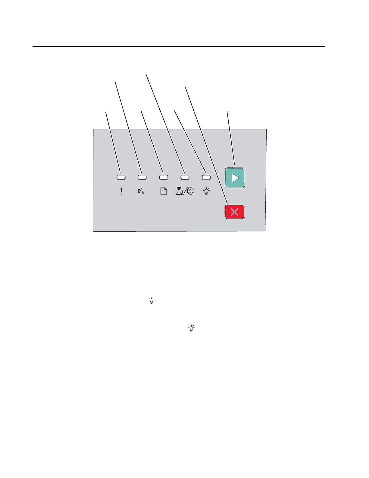
Error
light
Cancel
button
Continue
button
Paper
jam
light
Load
paper
light
Toner
light
Ready
light
Overview of the operator panel
Power-On Self Test (POST) sequence
When the printer is tur ned on, it perfor ms a POST. Check for correct POST functi oning of the base printer by
observing the following process:
1. All operator panel lights on moment arily
2. Lights then flash on and off sequentially.
3. Af ter the light s quit fl ashing, the light flashes unt il the fuser comes up to temperature (5-20 additional
seconds, depending on the initial temperature of the fuser) and then stays on.
4. I f t here is a problem in the pr int er such as a paper jam, then t he panel lights indicate the problem. See
“Common primary light patt erns” on page 2-4 fo r more inform at io n .
5. The printer cycles down into sta ndby m ode, and lights solid.
2-2 Lexmark™ E260, E260d, E260d n
Page 31

4513-200, -220, -230
Secondary CodesPrimary Codes
Double-
click
Light patterns and error messages
User attendance messages, paper jam errors, and service erro rs di splay a light pattern. This may be all the
information that is needed. However, if is double-clicked on the panel, a second pattern may appear with
more detailed information. If is double-clicked again, the first pattern usua ll y returns. Not all initial level light
patterns have secondary patterns. In which case, when double -cl icking, the pattern does not change.
All service errors are indicated by all lights flashing as the primary notification or code. The secondary code
indicates an area or function which has the error. Additional tertiary codes used for service (see “Ser vice
tertiary error codes” on page 2-30) indicate specific errors. See “Service codes” on page 2-28.
Note: If data is sent to the printer and all lights flash immediately, and double-clicking does not change the
display, then there may be a code probl em . Contact the next lev el of support.
Diagnostics information 2-3
Page 32

4513-200, -220, -230
Common primary light patterns
See “Overview of the operator panel” on page 2-2 for icon information.
Light on
Light off
✷ Light blinking
x Light blinking slowly
Common light sequences
Printer Condition Page
Ready/Power Saver 7
Demo Mode Ready 7 ✷
Busy
• Defragmenting Fl ash
• Formatting Flash
• Printing Direct ory
• Printing Font List
• Printing Menu Setti ngs
• Printing the Prin t Quality Test
Page
• Programming Flash
Hex Trace Ready 8 x
Waiting 8
Flushing buf fer/Resolution reduced9 ✷✷
Not ready
(printer is offline)
Close door or Insert Cartridge
Unsupported Flash Option
Installed
Cancel job
Reset printer
Restore factory defaults
Invalid engine code
Invalid network code
Resolution reduced while
canceling job
Toner cartridge region mismatch
Change cartridg e invalid refill
Missing or defect ive print cartridge
Unsupported print cartridge
Photoconductor kit life warning¹ 12 ✷
Programming engine code/
Programming system code
Service error² 13 ✷✷ ✷ ✷ ✷ ✷
Printe r er ro r ³ 13
8 ✷
9
10
10
11
11 ✷ ✷
12
13
2-4 Lexmark™ E260, E260d, E260d n
Page 33

4513-200, -220, -230
Printer Condition Page
Paper jam printer error (2xx) 14
Remove paper from output bin 14 ✷
Load media in Tray 1 or Tray 2 14
Load Media in Multi-purpose
Feeder or Manual Feeder
Load Tray 1 for side 2 of manual
duplex print ing
¹ Toner low light will rema in f lashing with other primary light sequences.
² Secondary codes, and often a tertiary code, will follow thi s code.
³ Secondary codes will f ollow this code.
15
15 ✷
Common light sequences when the toner is low
Printer Condition Page
Toner low¹ 11
Ready and Toner Low/Power
Saver and Toner Low
Demo Mode Ready and Toner Low ✷
Hex Trace Ready and Toner Low x
Busy and Toner Lower
• Defragmenting Fl ash and
Toner Low
• Formatting Flash and Toner
Low
• Printing Direct ory and Toner
Low
• Printing Font List and Toner
Low
• Printing Menu Settings and
Toner Low
• Printing Print Quality Test
pages and Toner Low
• Programming Flash and Toner
Low
Resolution red uced/Flusher buffer
and Toner Low
Waiting and Toner Low
Not Ready and Toner Low
Replace Photoconductor and
Toner Low
¹ Toner low light will rema in on with other primary l ight sequences.
✷ ✷
✷
Diagnostics information 2-5
Page 34

4513-200, -220, -230
Common light sequences when replacing the photoconductor
Printer Condition Page
Replace photoconductor
(printer hard stop)
Ready and Replace
Photoconductor/Power Save and
Replace Photoconductor
Demo Mode Ready and Replace
Photoconductor
Hex Trace Ready and Replace
Photoconductor
Busy and Replace Photoconductor
• Defragmenting Fl ash and
Replace Photoconductor
• Formatting Flash and Replace
Photoconductor
• Printing Direct ory and Replace
Photoconductor
• Printing Font Lis t and Replace
Photoconductor
• Printing Menu Settings and
Replace Photoconductor
• Printing Print Quality Test
pages and Replace
Photoconductor
• Programming Flash and
Replace Photoconductor
Resolution red uced/Flushing buffer
and Replace Photoconductor
Device is printi ng and Replace
Photoconductor
Waiting and Replace
Photoconductor
Not Ready and Replace
Photoconductor
Replace Photoconductor IR ✷✷
12 ✷✷
✷
✷ ✷
✷ x
✷✷
✷✷✷
✷✷✷
✷
✷
2-6 Lexmark™ E260, E260d, E260d n
Page 35

4513-200, -220, -230
Primary codes
Ready/Po wer Saver
Meaning
• The print er i s ready to receive and process data.
• The printer i s in Power Saver mode.
Action
• Send a print job.
•Press Continue to print the menu settings pages fo r a li st of current printer settings.
• Press and hold Cancel to reset the pri n te r.
Demo Mode Ready
Meaning
• The printer is in the Ready state and the Demo Mode is active.
• The printer is ready to re ceive and process data from a host system.
Action
Press Continue briefly to print the next Demo page .
✷
Diagnostics information 2-7
Page 36

4513-200, -220, -230
Busy
✷
Meaning
• The printer is busy receiving and processing data or printing.
• The printer is printing a directory , font list, menu settings pages, or Print Qualit y Test Pages.
• The printer is defragmenting, formatting, or programming Flash.
Action
Busy:
• Wait for the m es s a ge to cle a r.
• Press and release Cancel to cancel the print job.
• Press and hold Cancel to re s et the printer.
Printing a directory, a font list, menu settings pages, or Pr int Quality Test Pages:
• Wait for the pages to print. The Read y li ght flashes as the pages print. The Ready li ght is on when the printing
stops.
• Press and release Cancel to cancel printing.
• Press and hold Cancel to re s et the printer.
Hex Trace Ready
x
Meaning
The printer is in the Ready mode, and Hex Trace is active.
Action
• Advanced users can use Hex Trace to help troubleshoot printing problems. After resolving the problem, turn off
the printer to exit Hex Trace. Wait for the message to clear.
• Press and hold Cancel to re s et the printer.
Waiting
Meaning
The printer is waiting until a print timeout occurs, or until it receives additi onal data.
Action
•Press Continue to prin t th e contents of the print buffer.
• Press and release Cancel to cancel the print job.
• Press and hold Cancel to re s et the printer.
2-8 Lexmark™ E260, E260d, E260d n
Page 37

4513-200, -220, -230
Flushing buffer/Resolution reduced
✷
Meaning
• The printer is flushing corrupted print data.
• The printer is process ing data or printing pages, but the resolution of a page in the current pr int job is reduced
from 600 dots per inch (dpi) to 300 dpi to prevent a memory full error .
Action
• Wait until the control panel returns to Ready to print ot her j obs.
• Press and release Cancel to cancel the print job.
• Press and hold Cancel to re s et the printer.
✷
Not ready (p r inter is offline)
Meaning
The printer is not ready to receive or process data, or the printer ports are offline.
Action
• Press and release Continue to return to the Ready state.
• Press and release Cancel to return to the Ready state.
Diagnostics information 2-9
Page 38

4513-200, -220, -230
Close door or insert cartridge/Unsupported Flash option installed
Meaning
The printer front door is open, print car tridge is missi ng, or a flash option has been installed that is not supported.
Action
Close the door, install a print cartridge, or instal l a supported fla sh option. The printer will automatically re set.
Insuffic ie n t co l l ati o n ar ea/Insuffici en t memory
Meaning
The printer memory is too full to collate t he pri nt job.
Action
• Press and release Continue to clear the message and cont inue printing the job. (The job may not print
correctly.)
• Press and release Cancel to cancel the print job.
•Press Cancel to reset the printer.
Cancel job/Reset printer/Restore factor y defaults
Meaning
• The current print job is canceled.
• The printer is resetti ng to the user default settings. Any active print jobs are canceled. A user default sett ing
remains in effect until it is changed or has restored the factory default settings.
Action
Wait for th e m es s a ge to cle a r.
2-10 Lexmark™ E260, E260d, E260dn
Page 39

4513-200, -220, -230
Invalid engine code/Inv alid network code
Meaning
The engine code and/or the network code has not been programmed or has been programmed but is in valid.
Action
Download valid engine code to the internal pri nt server.
Resolution reduced while c anceling job
✷ ✷
Meaning
The printer is processesing data and/or printing and t he resolution of the page belonging to t he currently printing job has
been reduced from 600 dpi to 300 dpi in order to prevent a Memory Full error.
Action
Pressing Cancel will cancel the print job. Other buttons are ignor ed.
Toner low
Meaning
The printer is ready to receive and process data. In addition, the toner i n the toner cartri dge is getting low.
Action
• Press and release Continue to clear the light sequence and continue processing the print job.
• Turn the printer off.
• Remove the toner cartridge, and shake it to redistri bute the remaining toner.
• Replace the toner cartr idge.
Diagnostics information 2-11
Page 40

4513-200, -220, -230
Toner cartridge region m ismatch/Change cartridge invalid refill/Missing or defective
print cartridge/Unsupported print cartridge
Meaning
The geographic regi on of th e printer does not match the geographic region of the in stalled toner cartridge.
Action
Remove the toner cartridge, and install a new toner cartridge that matches the region of the printer.
Photoconductor kit life warning
✷
Meaning
The photoconductor is almost full and should be replaced soon.
Note: The Toner Alar m must be turned on in the driv er for this message to appear. The factory default is Off.
Action
• Press and release Continue to clear the light sequence and continue printing.
• Replace the photocondu ctor kit.
Replace photoconductor (printer hard stop)
✷
Meaning
The photoconductor kit is full and must be replaced. The print er will not print any more pages until the photoconductor kit
is replaced.
Action
• Press and release Continue to print a photocond uctor kit instruction page.
• Replace the photocondu ctor kit.
✷
2-12 Lexmark™ E260, E260d, E260dn
Page 41

4513-200, -220, -230
Programming engine code/Programming system code
Meaning
New code is being programmed into the engine or firmware code flash.
Action
Wait for the message to clear. When the prin ter has finished programming the code, it per forms a soft rese t.
Servi ce error
✷
Meaning
The printer has a ser vice error, and printing has stopped.
Action
Press Continue twice to see the secondar y code. See “Service codes” on page 2-28 to locate the probl em .
✷✷✷✷✷
Printer error
Meaning
The printer has one of the following errors:
• Memory is full, insufficient to save what is in the buffer.
• A page is too compl ex to print or is shor ter than the set page margins.
• Resolution of a formatted page is reduced to 300 dpi.
• A font error occurred.
• Communicati on with the host computer is lost.
• Short media .
Action
•Press Continue twice quickly to see the secondary er ror code.
•Press Continue to clear the secondary m essage.
Diagnostics information 2-13
Page 42

4513-200, -220, -230
Paper jam printer error (2xx)
Meaning
The printer has a paper jam.
Action
•Press Continue twice quickly to see the secondary er ror code.
•Press Continue to resume printing once all the jammed pag es are cl eared from the paper path.
Remove paper from output bin
✷
Meaning
The output bin is full.
Action
• Remove printed pages from the output bin.
•Press Continue to clear the error code.
Load media in Tray 1 or Tray 2
Meaning
The printer is out of print media at the indicated source.
Action
• Load print me dia into the indi cated tray, and press Continue to resume printing.
•Press Cancel to reset the printer.
2-14 Lexmark™ E260, E260d, E260dn
Page 43

4513-200, -220, -230
Load media in multi-purpose feeder or manual feeder
Meaning
The printer prompts to load a single sheet of print media in the multi-purpose feeder or manual feeder.
Action
• Load print me dia into the manual fe eder.
•Press Continue to resume printing.
•Press Cancel to reset the printer.
Load media Tray 1 for S ide 2 of manual duplex printing
✷
Meaning
The printer prompts to load side 2 of a single sheet of print media in Tray 1 for duplex printing.
Action
• Load side 2 of a single sheet of print media in Tray 1.
•Press Continue to resume printing.
•Press Cancel to reset the printer.
Diagnostics information 2-15
Page 44

4513-200, -220, -230
Common secondary light patterns
Press and release Continue twice quickly to dis play the secondary error code light sequence. The following
table shows what these li ght sequences mean and where to go for help.
Common light sequences for pa per jams
When the Paper jam and Continue lights are both on, a paper jam has occurred with a
secondary error code.
Printer Condition Page
200: Paper jam at the input
sensor
201: Paper jam between the
input and exit sensor
202: Paper jams at the exit
sensor
231: Paper jam
(duplex rear)
232: Paper jam
(duplex front )
233: Paper jam (duplex) 19 ✷✷
234: Paper jam
(duplex: location unknown)
241: Paper jam in
Tray 1
242: Paper jam in
Tray 2
251: Paper jam in the manual
feeder
18
18
18
18 ✷
19 ✷
19 ✷
19
19
20
2-16 Lexmark™ E260, E260d, E260dn
Page 45

4513-200, -220, -230
Common light sequences for printer errors
When the Error and Continue lights are both on, a printer error has occurred with a secondary code.
Press and release Continue twice quickly to dis play the secondary error code light sequence. The following
table shows what these li ght sequences mean and where to go for help.
Printer Condition Page
Complex page 20
Insufficient collation area 21
Defective flash 21
Network interface errors 21
Resource save off–def icient
memory
PPDS font error 22 ✷
Invalid configuration 23 ✷✷✷✷
Insufficient defrag memory 22 ✷
22 ✷
ENA connection lost 23 ✷
Host interface disabled 23 ✷✷
Memory full 23
Short media 24
Flash full 24
Invalid engine code 24
Invalid network code 25 ✷
Toner cartridge region
mismatch
Change toner cartri dge / inval id
refill
Missing / Def ective toner
cartridge
Unsupported toner cartridge 26
Too many options attach ed 26
Unsupported Flash in slot 1 27
Unformatted Flash 27
Install MICR car tridge 27 ✷✷
MICR cartridge em pty 27 ✷
25 ✷
25 ✷
26
Diagnostics information 2-17
Page 46

4513-200, -220, -230
Secondary error codes
200: Paper jam at the input sensor
Meaning
A paper jam has occurred at the input sensor, which can be either after the print media leaves the tray and ent ers the
printer or in the manual feeder.
Action
Open the front door, remove the print cart ridge, and clear the paper jam.
201: Paper jams between the input and exit se nsors
Meaning
A paper jam has occurred. The jam m ed med ia is most likel y in t he fuser area under the toner cartridge assembly.
Action
Open the front door, remove the print cart ridge, and clear the paper jam.
202: Paper jams as a printed job exits the printer
Meaning
A paper jam has occurred as the print media is exiting the printer.
Action
Open the rear door, and clear the paper jam.
231: Paper jam (duplex rear)
✷
Meaning
The media did not arrive at th e duplex sensor, but did leave the printer exit sen sor.
Action
Open the rear door, and clear the paper jam.
2-18 Lexmark™ E260, E260d, E260dn
Page 47

4513-200, -220, -230
233: Paper jam (duplex)
✷✷
Meaning
A paper jam has occurred in the duplex unit before
Action
Remove the tray, open the duplex door and clear the paper jam.
234: Paper jam (duplex - unknown location)
✷
Meaning
A paper jam has occurred somewhere around the duplex unit before making the manual input sensor.
Action
Remove the tray, open the duplex door and clear the paper jam. Paper may also be accessible inside the rear door.
241: Paper jam in Tray 1
Meaning
A paper jam has occurred in Tray 1.
Action
Clear the paper jam after removing Tray or and/or Tray 2.
242: Paper jam in Tray 2 (250-sheet pr 5 50-sheet option)
Meaning
A paper jam has occurred in Tray 2.
Action
Clear the paper jam after removing Tray 1 and/or Tray 2.
Diagnostics information 2-19
Page 48

4513-200, -220, -230
251: Paper jam in the manual feeder
Meaning
A paper jam has occurred at the manual feeder.
Action
Clear the paper jam.
Complex page
Meaning
The page may not print correc tly be caus e the pri nt infor mation o n the page is t oo compl ex (t hat is, t oo large for th e print er
memory).
Action
•Press Continue to clear the error code and con tinue processing the print job (some of the print data may be
lost).
To avoid this error in the future:
• Reduce the complexity of the page by reducing the amount of text or graphics on the page and deleting
unnecessary download fonts or macros.
•Set Page Protect to On in the Local Pri nter Setup Utility.
• Install additional printer memory.
2-20 Lexmark™ E260, E260d, E260dn
Page 49

4513-200, -220, -230
Insuffic ie n t co l l ati o n ar ea
Meaning
The printer memory does not have th e free spac e neces sary to co llat e the print job. Thi s may happ en due to one of these
errors:
• Memory is full.
• A page is too compl ex to print.
• A page is shorte r t han the set page margi ns.
• Memory is insuffici ent to save what is in the buffer.
Action
•Press Continue to clear the message and cont inue printing the job. (The job may not print correctly.)
• Press and release Cancel to cancel the print job.
• Press and hold Cancel to re s et the printer.
To avoid this error in the future:
• Simpli fy the print job. Reduce the complexity of the page by reducing the amount of text or graphics on the page
and deleting unnecessary downloaded fonts or macros.
• Install additional printer memory.
Defectiv e F l ash
Meaning
The printer detects a def ective flash.
Action
Press Continue briefly and the normal operation will continue. The flash will be marked as bad and cannot be used
until the problem is resolved.
Network i n ter face errors
Meaning
The printer cannot establish communication with the network.
Action
Press Continue to clear the message and continue printing. (The previous print job may not print correctly.)
Diagnostics information 2-21
Page 50

4513-200, -220, -230
Resourc e save off - defic ie n t memory
Meaning
This error message ind icates that too much memory has been allocated to link buffers or that some printer settings are
using more memory than the defa ult setting.
Action
Add more memory, change link buf fers or rese t the printer setti ngs that have been changed.
PPDS Font error
Meaning
The printer does not have enough m emory to save the data in t he buffer.
Action
• Install additional memory.
•Press Continue to continue printi ng the job.
•Press Cancel to cance l th e print job.
✷
Insufficient defrag memory
Meaning
The printer memory does not have th e free spac e neces sary to co llat e the print job. Thi s may happ en due to one of these
errors:
• Memory is full.
• A page is too compl ex to print.
• A page is shorte r t han the set page margi ns.
• Memory is insuffici ent to save what is in the buffer.
Action
•Press Continue to clear the message and conti nue printing the job. (The job may not print correctly.)
• Press and release Cancel to cancel the print job.
• Press and hold Cancel to re s et the printer.
To avoid this error in the future:
• Simpli fy the print job. Reduce the complexity of the page by reducing the amount of text or graphics on the page
and deleting unnecessary downloaded fonts or macros.
• Install additional printer memory.
✷
2-22 Lexmark™ E260, E260d, E260dn
Page 51

4513-200, -220, -230
ENA connection lost
Meaning
The printer cannot establish communication with the network.
Action
Press Continue to clear the code and continue printing. (The previous print job may not print corr ectly.)
✷
Host inte rf ace disabled
Meaning
The printer USB or parallel por t has been disabled.
Action
Press Continue to clear the code. The printer di scards any pri nt jobs previously sent . Enable the USB or parallel port
by selecting a value other than Disabled for the USB Buffer or Parallel Buff er item in the Local Printer Settings Utility.
✷✷
Memory full
Meaning
The printer is process ing data, but there is not enough memory available to continue the job.
Action
•Press Continue t o clear the message and continue printing the j ob (the job may not print correctly).
• Press and release Cancel to cancel the print job.
• Press and hold Cancel to re s et the printer.
To avoid this error in the future:
• Simpli fy the print job. Reduce the complexity of the page by reducing the amount of text or graphics on the page
and deleting unnecessary downloaded fonts or macros.
• Install additional printer memory.
Diagnostics information 2-23
Page 52

4513-200, -220, -230
Short media
Meaning
The media length is too short to pri nt the formulated data. This occurs when the printer does not know the pri nt media
size loaded in the tray.
Action
• Make sure the pr int me dia that is loaded i s long enough.
• Open the fron t door, clear the paper path and close the door to resume printing.
•Press Continue to clear the code and continue printing the job.
•Press Cancel to cance l th e print job.
Flash full
Meaning
The printer signals that there is not enough free space in the f lash memory mode to hold t he resources that have been
requested to be written to flash.
Action
•Press Cancel to cance l th e print job.
•Press Continue t o clear the message and continue processing t he job.
All downloaded fonts and macros that are not writt en to flash will be deleted.
Invalid engine code
Meaning
The engine code has not been programmed, or the programmed code i s not valid.
Action
Download the valid engine code to the internal print server while this message is still on the panel.
2-24 Lexmark™ E260, E260d, E260dn
Page 53

4513-200, -220, -230
Invalid network code
Meaning
The code either in the contr oller board or network card is invalid.
Action
Download the valid network code to t he printer. It may be downloaded while this message is displayed.
✷
Toner cartridge region m ismatch
Meaning
The geographic regi on of th e printer does not match the geographic region of the in stalled toner cartridge.
Action
Remove the toner cartridge, and install a new toner cartridge that matches the region of the printer. The settings cannot
be changed without calli ng Lexm ark for a one-ti m e change.
✷
Change toner cartridge/invalid refill
Meaning
The toner in the toner cartridge is getting low, or an invalid refill toner has been installed.
Action
• Press and release Continue to clear t he light sequence and continue processi ng the print job.
• Turn the printer off.
• Remove the toner cartridge, and shake it to extend the life, or replace the toner cartridge with a valid toner
cartridge.
• Replace the toner cartr idge.
• Turn the printer on.
✷
Diagnostics information 2-25
Page 54

4513-200, -220, -230
Missing/Defective tone r cartridge
Meaning
The toner in the toner cartridge is getting low, or a defective toner cartridge has been detected.
Action
• Press and release Continue to clear the light sequence and cont inue processing the print job.
• Turn the printer off.
• Remove the toner cartridge, and shake it to extend the life, or replace the toner cartridge if it is defective.
• Replace the toner cartr idge.
• Turn the printer on.
Unsupported toner cartridge
Meaning
The toner cartridge is not supported by the printer.
Action
• Press and release Continue to clear the light sequence and cont inue processing the print job.
• Turn the printer off.
• Remove the toner cartridge, and replace i t wit h a supported toner cartridge.
• Turn the printer on.
Too many options attached
Meaning
This message indicates that to too many flash options have been attached.
Action
Press Continue briefly to clear the message. The option will be ignored.
2-26 Lexmark™ E260, E260d, E260dn
Page 55

4513-200, -220, -230
Unsupported flash in slot 1
Meaning
The printer detects t hat a flash memory module is installed in the DIMM dram slot. This error will occur at power on and
must be resolved befor e pri nting may continue.
Action
Power off the printer, and remove the unsupported option.
Unform atted flash
Meaning
The printer detects an unf ormatted flash at power on.
Action
Press Continue briefly to clear the message. The flash is marked as bad, and normal operat ion will continue. Flash
operations will not be allowed until flash is formatted.
Install MICR cartridge
✷✷
Meaning
The printer has detected that it requires the installation of a MICR cartridge in order to complete a print job that it has
received.
Action
Install a MICR cartri dge, and then close the cover to clear this message.
MICR cartridge empty
✷
Meaning
The RIP software has detected t hat the device’s i nstalled MICR cartridge is empty.
Action
Install a new regular or MICR cartr idge, and then close the cover to clear this message.
Diagnostics information 2-27
Page 56

4513-200, -220, -230
Secondary Codes
Primary Codes
Tertiary Codes
Double-
click
Double-
click
Service codes
All service errors are indicated by all lights flashing as the primary notification or code. The secondary light
pattern indicat es an area or func tion which has the er ror. Terti ary codes (shown on the followi ng pages) in dicat e
specific device errors. When all lights flash, double-click to see the secondary code. Double-click again to
see the tertiary code. Double-click a third time to return to the pri mary light pattern.
In the following example:
• The primary light pattern indicates a service error (all fl ashing). Double-click for more information.
• The secondary li ght pat tern indicates a fuser, toner sensor, or fa n error. Double-click for more
information.
• The tertiary light pattern indicates the fan has stalled. Double-click again, and the original primary li ght
pattern will appear.
Note:
• The printer cann ot di rectly determine that a fan has failed, but can se nse the higher temp erature at the
fuser or printhead.
• If data is sent to the printer and all lights flash simul taneously, and double-clicking does not produce a
secondary code, then there may be a code problem. Contact the next level of support.
Service primary code
When this code appears, double-click to reveal the secondary codes.
Service primary code
Lights
Primary code for service errors
See service secondary error cod e s
✷ Light blinking
✷ ✷ ✷ ✷ ✷ ✷
2-28 Lexmark™ E260, E260d, E260dn
Page 57

4513-200, -220, -230
Service secondary error codes
Service secondary codes
Lights
90x: Software ✷
90x: Software ✷ ✷ ✷
91x: DC motor or transfer roll ✷ ✷
92x: Fuser or toner sensor ✷ ✷
93x: Printhead, drive motor ✷ ✷ ✷
94x: LVPS servic e error ✷ ✷
95x: Controller board (NCRAM,
ROM, or NAND)
96: RAM memory ✷ ✷ ✷
97x: Network ✷ ✷ ✷ ✷
98x: Service paper port
communication error
99x: Service device erro r ✷ ✷ ✷
Programming error ✷ ✷ ✷
40 and 41 Unsupported firmware
card
✷ ✷ ✷
✷ ✷
✷ ✷ ✷ ✷ ✷
Diagnostics information 2-29
Page 58

4513-200, -220, -230
Service tertiary error codes
Service tertiary error codes
Service error codes are generally non-recoverable except in an intermittent condition when POR (power-on
reset) is perfor m ed which allows the pri nter to temporarily recover from the error. These error cod es are
recorded in the history file which can be reviewed through the Diagnos ti cs M enu. See “Diagnostics mode
selections” on page 3-8.
Note: All service errors are initially communicated by all lights flash ing which is the pri ma ry i ndication or code.
For brevity, thi s indication is not repeated in the following codes.
CAUTION: When this symbol appears, there is a danger fro m hazardous voltage in the area of the
product that is bei ng worked on. Unplug the product before beginning, or use caution if the product
must receive power in order to perform th e task.
Controller software
Codes 90x indic ate a cont roll er sof tware er ror/ illegal trap. For th e oth er err ors, which i ndica te a faul ty pr ogra mming proce ss
or faulty compone nt on the controll er board, replace the controll er board. See “Controller board remo val” on page 4-6.
Service tertiary error codes: controller software
Lights
Service secondary cod es: 90x ✷
Service tertiary codes
900: Service RIP software error ✷
901: Service engine flash error ✷ ✷
902: General engine software error ✷ ✷
903: Service engine software error ✷ ✷ ✷
904: Service engine software error ✷ ✷
905: Interface violation by paper
port device
906: Service engine software error ✷ ✷ ✷
Service watchdog: 90x ✷ ✷ ✷
901: Timer service slow ✷ ✷ ✷
✷ ✷ ✷
2-30 Lexmark™ E260, E260d, E260dn
Page 59

4513-200, -220, -230
Transfer rol l o r tray 2
Code 914 indicates an error in tray 2 motor. Replace the drawer.
Code 917 indicates a problem in the transfer roll circui tr y. Check the continuity from the cable connection on the
HVPS (high voltage power supply) to the right side of the transfer roll.
Service terti ary error codes: tr ansfer roll
Lights
Service secondary cod es: 91x ✷ ✷
Service tertiary codes
910: Service DC motor error ✷
914: Tray 2 motor failure ✷ ✷
917: Transfer roll circuity ✷ ✷ ✷ ✷
Fuser, fan, or toner sensor error
Codes 920 through 929 indi cate a problem in the fuser, a stalled fan motor, or a faulty toner sensor or toner
cartridge. Multiple errors indicate repl acing the corresponding part.
Service tertiary error codes: fuser, fan, or toner sensor
Lights
Service secondary cod es: 92x ✷ ✷
Service tertiary codes: fuser, fan, or toner sensor
920: Fuser below temperature
when printing
921: Fuser below standby
temperature at idle
922: Fuser failed to reach standby
temperature
923: Fuser too hot during printing
or idle
924: Open circuit in therm istor path ✷ ✷
925: Incorrect fuser ✷ ✷ ✷
926: Service fuser error ✷ ✷ ✷
927: Fan stalled ✷ ✷ ✷ ✷
929: Toner sensor or toner
cartridge is bad
✷ ✷
✷ ✷
✷ ✷ ✷
✷ ✷ ✷
✷
Diagnostics information 2-31
Page 60

4513-200, -220, -230
Printhead, transport m otor, or RIP/engine communication error
Codes 930 through 935 indicate a problem with the printhead. Check cables to th e pri nthead. Replace the
printhead as necessary.
Codes 936 and 937 indicat e a problem in the drive system motor.
Code 939 indicates a communication failure between the RIP and engine processors.
Service tert iary error codes: printhead, transport motor, or RIP engine communicator
Lights
Service secondary cod es: 93x
Service tertiary codes: pri nthead, transport motor, or RIP engine communicator
930: Printhead error (wrong
printhead is installed)
931: Printhead error ✷ ✷
932: Printhead error ✷ ✷
933: Printhead error ✷ ✷ ✷
934: Printhead error ✷ ✷
935: Printhead error ✷ ✷ ✷
936: Printhead transport motor
error
937: Printhead transport motor
error
✷ ✷ ✷
✷ ✷ ✷
✷ ✷ ✷ ✷
RIP/engine communication or engine card error
Error code 940 indic ates a c ommunic ation fail ure bet ween the RI P and engine pr ocessor s. Error codes 948– 949
indicate engine card failure.
✷
Lights
Service secondary cod es: 94x
Service tertiary codes: RIP engi ne com municator or engine card
940: LVPS or cable has failed ✷
948: Service engine card failure ✷ ✷
949: Service engine card failure ✷ ✷ ✷
2-32 Lexmark™ E260, E260d, E260dn
Page 61

4513-200, -220, -230
NVRAM failure
Error codes 950–954 indicate a problem in the NVRAM (nonvolatile random access memory). Replace the
operator panel assembly. Codes 955–959 indicate a failed controll er board assembly. Replace the controller
board.
Service tert iary error codes: NVRAM failure
Lights
Service secondary cod es: 95x ✷ ✷ ✷
Service tertiary codes: NVRAM failure
950: Secure EEPROM data does
not match NVRAM
951: Secure EEPROM f ailure ✷ ✷
952: NVRAM CRC failure ✷ ✷
954: NVRAM chip failure ✷ ✷
955: Code ROM or NAND failed
CRC
956: Processor failure ✷ ✷ ✷
957: ASIC failur e ✷ ✷ ✷ ✷
958: NAND failure ✷ ✷
959: SRAM failure ✷ ✷ ✷
✷ ✷ ✷
✷
RAM memory error
Indicates an er ror in the RAM memory.
Lights
Service secondary cod es: 96x
Service tertiary codes: RAM memory error
960: Service RAM memory error ✷
961: Service RAM memory error ✷ ✷
962: Service RAM memory error ✷ ✷
963: Service RAM memory error ✷ ✷ ✷
Diagnostics information 2-33
Page 62

4513-200, -220, -230
Network error
Indicates an error in the net work circuitry. Replace the controller board assembly.
Service tertiary error codes: network error
Lights
Service secondary cod es: 97x ✷ ✷ ✷ ✷
Service tertiar y codes: network error
970: Service network error ✷
971: Service network error ✷ ✷
972: Service network error ✷ ✷
973: Service network error ✷ ✷ ✷
974: Service network error ✷ ✷
975: Unrecognizable network port ✷ ✷ ✷
976: Unrecoverable software error
in network port
977: Service network error ✷ ✷ ✷ ✷
978: Bad checksum while
programming port
979: Flash parts failed while
programming port
✷ ✷ ✷
✷ ✷ ✷
✷ ✷
Paper port communication error
Indicates a communication error in the paper port.
Lights
Service secondary cod es: 98x
Service tertiary codes: paper port communication error
980: Service paper port
communication failure
981: Service paper port
communication failure
982: Service paper port
communication failure
983: Service paper port
communication failure
984: Service paper port
communication failure
✷ ✷
✷ ✷
✷ ✷ ✷
✷
✷ ✷
2-34 Lexmark™ E260, E260d, E260dn
Page 63

4513-200, -220, -230
Device equipment check or device controller board error
Indicates a fail ure with the device’s equipment or controll er board.
Lights
Service secondary cod es: 99x
Service tertiary codes: device equipm ent check or device controller board error
990: Service device equipment
check
991: Service device controller
board failure
✷ ✷
✷
Diagnostics information 2-35
Page 64

4513-200, -220, -230
Messag es an d erro r code s
Note: The following message and error codes will be visible only in the print event log in the diagnostic
mode for E260, E260d, and E260d n. See “Diagnostics mode selections” on page 3-8.
The printer operator panel displays light patterns d escribing the current state of the printe r and indicates
possible pri nter problems that must be resolved. This topic provides a list of all printer messages and explains
what they mean.
User attendance messages
Cartridge error codes
Error Description Action
30 Invalid refill Replace the cartri dge.
31 Missing or defective cartridge
32 Unsupported cartridge
Paper jam error codes (200-series)
Repeating jams or jam messages can be caused by any of the following:
• Faulty/contam inated pick solenoids or worn cams of the solenoids.
• Faulty/contaminated flags or springs.
• Debris in the paper path .
• Media not of the specifi ed length.
• Faulty media feed clutch. See “Media feed clutch service check” on page 2-56.
Paper jam error codes (200-serie s)
Error Description Action
200.00 Paper jam around input sensor. Remove the PC kit and paper or debri s at the input
200.01 Clas sic input jam. The media is too long over the input
sensor. Possible causes include multi-sheet feed, tray
size sensing problem , and media slip page.
200.02 The main input sensor never became uncovered from
the sheet ahead.
200.03 The vi deo never started on the page at the input
sensor within two inches after hitting the input sensor
200.04 The media at the input sensor before interrupt
occurred–not eno ugh time el aps ed since the pri nthead
started to expect the printhead mirror motor lock.
Possible causes inc lude bouncy sensor or
exceptionally fast pick– perhaps due to media prestaged in the source tray.
sensor.
First, remove the PC kit and paper or debri c at t he
input sensor . Then, inspect the f lag on the input
sensor. It sh ould rotate free ly. Replace the sensor if
necessary. Finally, check the paper size settin gs in
the printer and the driver.
Check the printhead. See “Printhead service
check” on page 2-67.
Carefully remove the tray and notice if the leading
edge of the media is pointed upward and out of the
tray. If so, then inspect the tr ay wear strips and
replace if necessary.
Inspect the input sensor flag and replace it if it does
not rotate freely or is too loos e.
200.06 Imaged page not expect ed page (bouncy passthru
sensor)
2-36 Lexmark™ E260, E260d, E260dn
Remove the toner cartridge/PC kit. At th e fro nt,
remove the uppe r f ront guide, and ins pect the f lag on
the manual input sensor. If the flag is loose, then
replace it. See “Media manual input sensor
removal” on page 4-42.
Page 65

4513-200, -220, -230
Paper jam error codes (200-series) (Continue d)
Error Description Action
200.08 Media reached the input sensor before t he EP was
ready
200.09 Tran sfer servo never started Inspect the LVPS/HVPS. See “Controller board
200.12 Media detected at manual feeder sensor when not
expected. Possib le causes inc lude user insert of media
when motor is running or pre- staged media in the tray.
200.13 The in put sensor is covered when the media is not
expected (media in machine during warm-up)
200.14 Trai ling edge cleared manual feed, but did not
successfully debounce the sensor. Potential causes
are a small gap or a bouncy manual feed sensor.
200.15 UNRECOVERABLE NO GAP JAM. Engine detected
no gap at the manual feeder sensor, attempted to open
the gap by stopping the feed rolls, but no trailing edge
was ever seen at the input sensor.
Inspect the tray for prestaging. Verify the proper
media and inspect the tray wear strips. Replace the
wear strips if necessary.
service check” on page2-52.
Carefully remove the tray and notice if the leading
edge of the media is pointed upward and out of the
tray. If so, then inspect the tr ay wear strips and
replace if necessary.
Inspect the input sensor flag and replace it if it does
not rotate freely or is too loos e.
Remove the toner cartridge/PC kit and inspect the
input sensor f lag. Replace the flag if necessary.
Remove the toner cartridge/PC kit. At th e fro nt,
remove the uppe r f ront guide, and ins pect the f lag on
the manual input sensor. If the flag is loose, then
replace it. See “Media manual input sensor
removal” on page 4-42.
Remove the toner cartridge/PC kit. At th e fro nt,
remove the uppe r f ront guide, and ins pect the f lag on
the manual input sensor. If the flag is loose, then
replace it. See “Media manual input sensor
removal” on page 4-42.
Verify that the media is approved. Inspect the wear
strips in the input tray, and re place if necessary.
200.16 Transport motor error detected Inspect the mai n motor. See “Main motor service
200.17 Took too long to ramp up trans port motor
200.18 Manual feeder sens or never became uncovered from
the sheet ahead.
200.19 The m edia never reached the input sensor, but was
detected at manual fee der sensor.
200.20 The m edia is too long over the manual feeder sensor.
Possible causes inc lude multi-sheet feed, media size
(length) problem, pre-staged media in the tray.
200.22 FAILED SMALL GAP OR NO GAP JAM RECOVERY.
Engine detected small gap or no gap at the manual
feeder sensor, opened the gap by stopping the feed
rolls, but never saw the leadi ng edge of the second
page at the input sensor.
200.23 Laser Servo never started due to potential conflict with
the transfer servo. Possible causes: slow or missing
transport motor positional feedback, or the media is
transferred too qui ckly to the input sensor.
check” on page 2-55.
Remove the toner cartridge/PC kit. At th e fro nt,
remove the uppe r f ront guide, and ins pect the f lag on
the manual input sensor. If the flag is loose, then
replace it. See “Media manual input sensor
removal” on page 4-42.
Remove the toner cartridge/PC kit, and inspect for
debris in the paper pat h. Check t he bottom of t he PC
kit for any obstructions. Remove the upper front
guide, and inspect the pinch rollers.
Verify that the media is approved. Inspect the wear
strips i n the tray, and replace if they are worn.
Verify that the media is approved. Inspect the wear
strips i n the tray, and replace if they are worn.
Check the main motor. See “Main motor service
check” on page 2-55.
Diagnostics information 2-37
Page 66

4513-200, -220, -230
Paper jam error codes (200-series) (Continue d)
Error Description Action
200.24 The measured gap at the input sensor is too small to
meet the video delivery requirements. (There is not
enough time since prior image finished to start new
image)
200.26 The tr ailing edge never cleared the input sensor when
feeding out t he media that was detected during warmup.
200.27 Printhead Driver: Mirror motor fell out of lock condition
after the media a t t he input sensor–more time elapsed
since the printhead th an the expect ed st able loc k time,
but less than the printhead jitter-stable specification.
Mirror motor fell out of lock co ndition af ter me dia at the
input sensor–more t ime el apsed since the pr inthead
than expected stable lock time, but less than the
printhead jitt er-stable specification.
200.28 First writing line of a page at the developer nip, but
laser servo clean up is not com plete. Likely pre staged
media or a fast paper feed.
200.29 Printhead drive control out of range due to an external
event beyond what the control is designed to handle.
Probable causes: ESD or noise on hsync signal.
200.30 Narr ow me dia sensor covered during warm-up. Check that the narr ow m edia flag rotat es fr eely and
Verify that the media is approved. Inspect the wear
strips i n the tray, and replace if they are worn.
Check the printhead. See “Printhead service
check” on page 2-67.
Verify that the media is approved. Inspect the wear
strips i n the tray, and replace if they are worn.
Check the cable routing for the printhead. See
“Printhead service check” on page 2-67.
securely. If it i s disl odged or broken , then r epalce t he
rear exit guide. See “Rear exit guide assembly
with sensor and reversing solenoid removal” on
page 4-51.
200.32 Media more than 14 inches too long over the manual
feeder sensor. Poss ibl e causes include multi-sheet
feed or pre-staged media in the tray.
200.33 Page fr om tr ay 1 did not reach the input sensor after
multiple attempts. Page did make it out of the tray at
least as far as the manual feeder sensor. Possi ble
cause is that the page stalled at the alignment gat e.
200.34 Timed out waiting for page from tray 1 to reach the
input sensor after multiple pic k att em pts, but the page
was later detected at the input sensor while wai ting for
any page(s) ahead to clear the paper path. Possible
cause is that the page is dela yed at the alignme nt
gate.
200.35 Fai led to create hsync during auto alignment Check t he pri nthead. See “Printhead service
200.36 Lost hsyncs during auto alignment
200.37 Timeout on data collection during auto alignment
200.38 Int erpage servo gap is smaller than expected for
printhead offset t arget evaluation
200.42 Rogue sheet is at the manual feed sensor while
flushing the paper path prior to declaring MPF source
empty.
Verify that the media is approved. Inspect the wear
strips i n the tray, and replace if they are worn.
Verify that the pi ck tires are clean, not worn, or filled
with paper dust. Replace the pi ck tires if necessary.
See “ACM pick tire roll er removal” on page 4-3.
The alignment ro ll er may be binding. Call the next
level of support.
check” on page 2-67.
Retry alignmen t.
2-38 Lexmark™ E260, E260d, E260dn
Page 67

4513-200, -220, -230
Paper jam error codes (200-series) (Continue d)
Error Description Action
200.43 The m edia is at the input sensor before interruption
occurs. Possible causes include bouncy sensor or an
exceptionally sm all gap, perhaps due to the media
being pre-staged in the source tray.
201.00 Paper jam between input and ex it sensor Remove the toner cartridge/PC kit and check for
201.01 Transport motor identification failed to identif y either
moto r af te r tw o tri e s.
201.02 Exi t sensor never made by leading edge of page. Also
known as internal jam.
201.03 Video never started on the page at the input sensor
within two inches after hitting the input sensor
201.05 Restar t attempted after an internal jam without the
cover open/close event. It is likely that the jam was
never cleared.
201.25 Exi t sensor never made by leading edge of media
when feeding out the media that was detected during
warm-up.
201.26 Page at f user nip before fuser started ra mp ing toward
desired temperat ure. Indicates code may be receiv ing
more interrupts than i ntended
Remove the media, real ign the stock, and re-insert.
Do not let the top sheets to go beyond the wear
strips.
obstructions between the input sens or and the fuse r.
if the media continues to stop at the entrance or in
the fuser, then replace the fuser. See “Fuser
removal” on page 4-20.
Check the main motor. See “Main motor service
check” on page 2-55.
Remove the PC kit and paper or debri s at the input
sensor.
Check the printhead. See “Printhead service
check” on page 2-67.
Check the paper path and remove any media in the
path.
Remove the toner cart ridge/PC kit and check for
obstructions between the input sens or and the fuser.
if the media continues to stop at the entrance or in
the fuser, then replace the fuser. See “Fuser
removal” on page 4-20.
201.27 Page at f user nip before fuser reached acceptable
202.00 Paper jam around exit sensor. Open the rear cover and look for obstructions in the
202.01 Exi t sensor never broke on the trailing edge of the
202.02 Exi t sensor never broke from sheet ahead of page
202.06 Exi t sensor bounced
202.13 Exi t sensor cov ered, medi a not expect ed (med ia not in
202.25 Exi t sensor never broke from the sheet ahead of the
202.26 Trai ling edge neve r cleared exit sensor when feeding
operating temperature. Page arrived at fuser earlier
than expected, so it was probably staged prematurely.
sheet at the exit sensor.
heading toward the exit sensor.
machine during warm-up )
page heading toward the exit sensor when fee ding out
the media detected during warm-up.
out media that was detected during warm-up.
path way. If there are none, then inspect for damage
at the fuser, rear door, exit guide, and top cover.
Often, the leading edge of the media wil l indicat e the
vacinity of damage. If damage is found, then replace
the damaged part.
Note: Print a page wit h the rear door open to i solate
the fuser from the other parts.
Open the rear door, and inspect the flag on t he exit
sensor. The flag is located behind the fuser exit
rollers, about mid printer . If the flag does not rot ate
freely or has no spring action, th en replac e the fuser .
See “Fuser removal” on page 4-20.
Open the rear door, and inspect the flag on the exit
sensor. The flag is located behind the fuser exit
rollers, about mid printer . If the flag does not rot ate
freely or has no spring action, th en replac e the fuser .
See “Fuser removal” on page 4-20.
Diagnostics information 2-39
Page 68

4513-200, -220, -230
Paper jam error codes (200-series) (Continue d)
Error Description Action
202.32 Long media or shingled multi feed stopped before
sending to duplex.
231.00 Dupl ex jam while reversing into the device Open the rear cover and look for obstructions
231.01 Dupl ex sensor never made by leading edge reversing
into the duplex.
231.02 Bouncy duplex sensor never made.
232.00 Dupl ex jam while staging i n the device
232.01 Dupl ex sensor never broke by the sheet ahead after
reversing into the duplex.
232.02 Page in duplex ahead of current reversing page never
staged.
233.00 Duplex jam while pick ing from the device
233.01 Page in duplex never picked.
233.02 Feed error picking from the duplex.
233.03 Paper never reached the input sensor, but was
detected at the manual feed sensor.
Check the paper setti ng and cor rect if nee ded. While
feeding along the media, and immediately after it
enters the output bin, open the reat door and
obscure the t rail ing edge and t he sensor f lag. If the re
is slippage in the exit guide, then replace the exit
guide. See “Rear exi t guide asse mbly wi th senso r
and reversing solenoid removal” on page 4-51.
between the rear cover ribs, the fuser exit rollers,
and below. The media ent ering the duplex passes
outside the exit roller while the media exiting the
fuser passes above and inside the exit rollers.
Remove the tray, open the duplex door, and remove
the obstructions. If there are no obstructions and the
problem persists, then disconnect all of the cables,
tilt the printer onto its back (be sure to protect the
antenna on a wirele ss unit), and inspect the flag of
the duplex sensor . If the flag does not rotate freely,
then replace the paper input and duplex sen sor. See
“Paper input and duplex sensor assem bly
removal” on page 4-47.
Check the belt and drive of the duplex unit. Replace
it if necessa r y.
234.01 Dupl ex sensor covered during warm-up.
235.01 Inv ali d duplex media Check the media. Duplex supports A4, letter, legal,
241.00 Paper jam near tray 1. Remove the tray and inspect the media path for
241.10 Second pick attemp t fa il ed from Tray 1
241.12 Second pick from manual feeder, tray 1, or feeder
failed when the media was in the sou rce while other
sheets were committed to the paper path.
241.16 Fail ed to feed from tray 1. Pages in the paper path
have been flushed to the output bin.
241.17 MISIDENTIFIED SMALL GAP JAM. Engine detected
small gap at the manual feeder sensor, attempted to
open the gap by stopping the feed ro lls, trailing edge
was seen at the input sensor, manual feeder sensor is
no longer covered.
241.19 Second pick attempted fail ed from Tray 1, no pages
printed since calling a 241.10 or a prior 241.19.
242.00 Paper jam near tray 2. Remove Tray 2 and inspect for obstruction in the
oficio, and folio media sizes.
obstructions . Check the pick roll ers. Replace th e pick
rollers if they are worn or clogged wit h dust. See
“ACM pick tire roller remov al” on page 4-3. Also
check the wear strips, and replace if necessary.
Remove the tray and inspect the media path for
obstructions . Check the pick roll ers. Replace th e pick
rollers if they are worn or clogged wit h dust. See
“ACM pick tire roller remov al” on page 4-3. Also
check the wear strips and the manual feeder, and
replace if necessary.
paper path. Check t he pick tires for wear or pap er
dust. Replace if necessary. Check the wear strips
and replace if necessary.
2-40 Lexmark™ E260, E260d, E260dn
Page 69

4513-200, -220, -230
Paper jam error codes (200-series) (Continue d)
Error Description Action
242.01 Took too long to ramp up dc feed motor Check the connection with Tray 2. (Lift the printer
242.08 Recei ved lots of dc feed interrupts before losing them
242.10 Second pick attempt failed from Tray 2 Remove Tr ay 2 and inspect for obstruction in the
242.12 Second pick from manual feeder, tray 1, or feeder
failed when media was in the source, other sheets
were committed to the paper path.
242.16 Fail ed to feed from tray 2. Pages in the paper path
have been flushed to the output bin.
251.00 Paper jam near the manual feeder. Inspect the pick roll er on the MPF or the roller s on
251.10 Second pick attemp t fa il ed from manual feeder.
251.11 Fai led to feed from manual feeder. Pages in the paper
path have been flushed to the output bin.
251.12 Second pick from manual feeder, tray 1, or feeder
failed when media was in the source whil e the other
sheets were committed to the paper path.
251.19 Media nev er reac hed the i nput sen sor f rom t he ma nual
feeder.
and re-set it on Tray 2.) If the error persists, then
replace Tray 2.
paper path. Check t he pick tires for wear or pap er
dust. Replace if necessary. Check the wear strips
and replace if necessary.
Check the wear strips and replace them if worn.
Remove Tray 2 and inspect for obstruction in the
paper path. Check t he pick tires for wear or pap er
dust. Replace if necessary. Check the wear strips
and replace if necessary.
the manual f eed. I f the M PF pic k rol ler i s dama ged or
worn, then replace t he MPF. For a printer with a
manual feed only (no MPF), clean the rol ler.
251.20 The media in the MPF has been pushed i n too f ar. Remo ve the media, realign the stock, and re-insert.
251.21 The media in the MPF has been pushed i n too f ar.
Do not let the top sheets to go beyond the wear
strips.
Diagnostics information 2-41
Page 70

4513-200, -220, -230
Service error codes
Service error codes are generally non-reco verable except in an intermittent conditi on when the printer can be
put into POR to temporarily recover from the error condition.
Service error codes (9xx)
Error Description Action
Engine software service errors
900.xx Code detected unusual eve nt of timing See “Service software servi ce check” on
902.xx Engine software error Replace the contr oller board. See “Controller
DC pick motor errors
914.00 DC pick motor error
914.01 Lost encoder feedback
Transfer service errors
917.xx Transfer service error Replace the transfer roll. See “Service software
Fuser servic e errors
920.00 Under temperatur e during steady state control. Replace the fuser. See “Fuser service check”
920.01 Fuser took too lo ng to heat up aft er transitioning to new
enhanced mode.
920.02 Fuser fell too far below desired temperature while
printing.
920.03 Fuser too cool whi le checking for slope change.
920.04 Fuser too cool when heat ing to desired temperature
after slope change.
page 2-68
board service check” on page 2-52
service check” on page 2-68.
on page 2-54.
920.05 Fuser under temperatur e while printing
920.06 Fuser under temperatur e while printing
920.07 Fuser under temperatur e while printing
920.08 Fuser temperature did not increase after IR recovery.
920.20 Belt fuser under tempe ratur e duri ng stead y st ate co ntrol .
921.00 Under temperatur e during standby control.
921.01 Fuser temperature did not reach standby temperature
922.00 Fuser fail ed to ra m p to targ e t te m p e ra t ur e
922.01 Fuser did not reac h standby temperature in time
922.02 Hot roll took too long to re ach the beginni ng lamp
922.03 Hot roll reached final lamp detection temperature, but
This can occur in pr inting or standby modes.
after two at te m p ts
(standby control)
detection t em perature.
took longer than largest time in lookup table.
2-42 Lexmark™ E260, E260d, E260dn
Page 71

4513-200, -220, -230
Service error codes (9xx) (Continued)
Error Description Action
922.04 Hot roll timed out in trying to reach the final lamp
detection t em perature.
920.00 Under temperatur e during steady state control.
920.01 Fuser took too long to heat up after transitioning to new
enhanced mode.
920.02 Fuser fell too far below desired temperature while
printing.
920.03 Fuser too cool whi le checking for slope change.
920.04 Fuser too cool when heat ing to desired temperature
after slope change.
920.05 Fuser under temperatur e while printing
920.06 Fuser under temperatur e while printing
920.07 Fuser under temperatur e while printing
920.08 Fuser temperature did not increase after IR recovery.
920.20 Belt fuser under tempe ratur e duri ng stead y st ate co ntrol .
This can occur in pr inting or standby modes.
921.00 Under temperatur e during standby control.
921.01 Fuser temperature did not reach standby temperature
after two at te m p ts
Replace the fuser. See “Fuser service check”
on page 2-54.
922.00 Fuser fail ed to ra m p to targ e t te m p e ra t ur e
922.01 Fuser did not reac h standby temperature in time
922.02 Hot roll took too long to re ach the beginni ng lamp
922.03 Hot roll reached final lamp detection temperature, but
922.04 Hot roll timed out in trying to reach the final lamp
(standby control)
detection t em perature.
took longer than largest time in lookup table.
detection t em perature.
Diagnostics information 2-43
Page 72

4513-200, -220, -230
Service error codes (9xx) (Continued)
Error Description Action
922.05 Did not roll over to a steady state con trol in time afte r the
hot roll lamp detection.
922.06 Hot roll did not reach the operating temperature in time
(new enhanced control).
922.07 Media reached fuser nip, and fuser is under temperature
922.08 Fuser warm-up failure (motor start condit ion)
922.09 Fuser warm- up failure (compression set)
922.20 Belt fuser fail ed to reach the prehea t temp erature for the
motor to start during warm-up.
922.21 Belt fuser was under temperature when the media
reached the fuser nip.
923.00 Fuser is over temperature.
923.01 Fuser is over temperature. This applies to the fuser and
belt fusers.
924.00 Open thermistor check.
924.01 Open thermi stor check failur e. This applies to the fuser
and belt fuser s.
924.02 Open thermistor check failure. The ADC failed to
converge. Possible noisy thermistor signal. This applies
to the fuser and belt fusers.
Replace the fuser. See “Fuser service check”
on page 2-54.
925.xx Wrong fu ser installed. The fuser type stored in the
Fan service errors
927.00 Service fan error Replace the fan. See “Cooling fan service
927.03 Main fan took too long to ra mp up
927.04 Main fan is under speed or stalled during speed
927.05 Main fan overspeed during speed adjustment state.
927.06 Main fan capture data is invalid, and speed control is at
927.07 Main fan capture data is invalid, and speed control is at
Printhead service errors
930.00 Wrong printhead installed Replace the printhead. See “Printhead service
931.00 No first hsync
cartridg e ID does not match the actual fuser installed in
the printer.
check” on page 2-53.
adjustme nt state
maximum in fan control idle state
maximum in fan control adjustment state.
check” on page 2-67.
2-44 Lexmark™ E260, E260d, E260dn
Page 73

4513-200, -220, -230
Service error codes (9xx) (Continued)
Error Description Action
931.01 No first hsync Replace the printhead. See “Printhead service
932.00 Lost hsyncs
932.01 Lost hsyncs
933.01 Printhead boos t signal failure
934.00 Mirror motor lost lock.
934.01 Mirror motor lost lock.
935.00 No initial mir ror m o to r lo c k
935.01 Timed out waiting for mirror motor lock
935.10 Printhead sweep error, swept through Hz range without
finding t he resonant frequency
935.12 Printhead sweep error, coarse sweep state
935.15 Printhead open- loop error, check prelim amp state
935.16 Printhead open- loop error, enable amp Kp state
935.17 Printhead cl osed-loop error, amp Kp failed to converge
935.18 Printhead cl osed-loop error, enable amp Ki state
935.19 Printhead closed-loop error, amp Ki failed to converge
check” on page 2-67.
935.20 Printhead cl osed-loop error, enable offset controller
935.21 Printhead cl osed-loop error, load scan regs state
935.22 Printhead cl osed-loop error, fwd and rev capture times
935.23 Printhead cl osed-l oop erro r, check sweep acc uracy st ate
935.25 Printhead cl osed-loop error, off-resonant PI effort state
935.26 Timed out on POR sweep
935.27 Exceeded maximum open loop drive level when
935.28 Exceeded maximum open loop drive lev el when setting
Transport motor service errors
936.01 No lock detected at normal motor start Replace the main motor gear drive. See “Main
936.02 No lock detected at motor start for motor ID
936.03 No halls detect ed at motor start
936.04 Failed to stop within timeout
936.05 Stall det ected during speed control
state
differ by too much
configuring for sweep re-try.
operating Hz.
motor service check” on page2-55
Diagnostics information 2-45
Page 74

4513-200, -220, -230
Service error codes (9xx) (Continued)
Error Description Action
937.00 Main transpor t motor lost lock Replace the main motor gear drive. See “Main
937.01 Main transport motor lost lock, detected by engine
control
937.02 Overspeed detected during position control
937.03 Overspeed detected during speed control
Power supply service errors
940.00 LVPS service error Replace the LVPS/HVPS. See “LVPS/HVPS
940.01 Line frequency outside allowed range of 45Hz-64Hz
940.02 Line frequency below 43Hz
940.03 No zero cross detected on belt fuser model
Controller board and operator panel service errors
948.xx Failed engine board Replace the controller board. See “Controller
949.xx
950.xx Mismatch between EEPROM and mirror memory
Note: A n ew co ntrol ler b oard or ope rator panel has been
installed, and has not been properly prepared for this
use. Install a new not e. Do not install both th e controller
board and the operator panel at the s am e time without a
POR in between.
motor service check” on page2-55
service check” on page 2-55.
board service check” on page 2-52.
Install a new controller bored or operator panel.
See “Controll er board service check” on
page 2-52 or “Operator panel service check”
on page 2-57.
951.xx Error with secure NVRAM on the control ler board Replace the controller board. See “Controller
952.xx A recoverable MVRAM Cyclic Redundancy Check error
occurred.
953.xx NVRAM chip failure with mirror Replace the oper ator panel. See “Operator
954.xx NVRAM chip failure with system part. Replace the controller board. See “Controller
955.xx The code ROM or NAND flash fail ed the Cyclic
Redundancy Check or the NAND experi enced an
uncorrecti ble multi-bi t failure.
956.00 RIP card failure: processor failure
956.01 Processor overtemp
957.xx RIP card failure: ASIC fa ilure
958.xx Printe r has performed more than 100 “shift and reflash”
operations as a resul t of ECC bit corrections
Firmware or controller board errors
959.01 Controlle r ver if ication failure of pensive boot code Call the next level of support to updat e the
959.02 Failure to authenticate Signature Verification Code
board service check” on page 2-52.
Performing POR will clear this error.
panel service check” on page 2-57.
board service check” on page 2-52.
firmware, or repla ce the controll er board. See
“Controller board service chec k” on
page 2-52.
2-46 Lexmark™ E260, E260d, E260dn
Page 75

4513-200, -220, -230
Service error codes (9xx) (Continued)
Error Description Action
959.03 Signature Ver ificat ion Code f ail ed to aut hentic ate a code
partition.
959.04 Jump to unverified address
959.05 Unknown boot failure Update firmware and call the next level of
959.20 Pensive hardware failure Replace the controller board. See “Controller
959.21 Pensive did not respond to command re quest.
959.22 Challenge secret failure
959.23 Pensive self test failed during initialization. Replace the controller board. See “Contr oller
959.24 EEPROM retention error
959.25 Insufficient device space during HW prog
959.26 Incremental counter reset exceeds maximum value
959.27 Increment count failed due to max value limit
959.28 Invalid SP memory configuration
Memory and emulation errors
960.xx RAM memory error: RAM soldered on the contr oller
board is bad
Update firmware and call the next level of
support, or replace the controller board. See
“Controller board service chec k” on
page 2-52.
support, or replace the controller board. See
“Controller board service chec k” on
page 2-52
board service check” on page 2-52.
board service check” on page 2-52.
Replace the controller board. See “Controller
board service check” on page 2-52.
961.xx RAM memory erro r: memor y card in slot is bad. Replace the memo ry card.
964.xx Download Emulat ion Cyclic Redundancy Check Error:
checksum failure detected in the emulation header or
emulation file.
Network errors
975.xx Unrecognizable network Call the next level of support.
976.xx Unrecoverable software error in network port
978.xx Bad checksum while programming network port
979.xx Flash parts failed while programing network port
Other errors
980.xx Engine experiencing unreliable communication with the
specified device
981.xx Engine protocol violation detected by the specified
device
982.xx Communic ati ons error detected by the specified device
983.xx Invali d com m and received by the specified device
Disable the Download Emulat ion. Program the
download emulati on into the f irmware ca rd aga in.
If this does not resolve the problem, then replace
the firmware card and download the emulation
again.
Call the next level of support.
Diagnostics information 2-47
Page 76

4513-200, -220, -230
Service error codes (9xx) (Continued)
Error Description Action
984.xx Invali d com m and parameter received by the specidied
device
990.xx An equipme nt check condition has occurred in the
specified device, but the device is unable to identify the
exact compone nt failure.
991.xx The specified device has detected an equipment check
in its system card.
Call the next level of support.
2-48 Lexmark™ E260, E260d, E260dn
Page 77

4513-200, -220, -230
Paper Menu
Paper Source
Paper Size
Paper Type
Custom Types
Universal Setup
Substitute Size
Paper Texture
Paper Weight
PostScript
Menu
Print PS Error
Font Priority
USB Menu
PCL SmartSwitch
PS SmartSwitch
NPA Mode
USB Buffer
Mac Binary PS
Finishing Me nu
Copies
Blank Pages
Collation
Separator Sheets
Separator Source
Multip age Print
Multipage Order
Multipage View
Multipage Border
Job Menu
Cancel Job
Reset Printe r
Print Buffer
Utilities M enu
Quick Demo
Print Menus
Print Net Setup
Print Fonts
Print Directory
Print Demo
Factory Defaults
Hex Trace
Quality Menu
Print Resolution
Toner Darkness
PictureGrade™
Setup Menu
Eco-Mode
Quiet Mode
Printer Language
Power Saver
Resource Save
Download Target
Print Timeout
Wait Timeout
Auto Continue
Jam Rec ov e r y
Page Protect
Print Area
PCL Emul Menu
Font Source
Font Name
Point Size
Pitch
Symbol Set
Orientation
Line s per Page
A4 Width
Tray R enumber
Auto CR after LF
Auto LF after CR
Parallel Menu
PCL SmartSwitch
PS SmartSwitch
NPA Mode
Parallel Buffer
Advanced Status
Protocol
Honor Init
Parallel Mode 2
MAC Binary PS
Network Menu
PCL SmartSwitch
PS SmartSwitch
NPA Mode
Network Buffer
Mac Binary PS
Std Net Setup
PPDS Menu
Orientation
Lines per Page
Lines per Inch
Page Format
Character Set
Best Fit
Tray 1
Renumber
Auto CR after LF
Diagram of the printer menus
Not all menus or selections will be available on all models or in all situations. These are accessed through the
driver.
Diagnostics information 2-49
Page 78

4513-200, -220, -230
Sympto m tab l e s
POST symptom table
Note: Investigate any displayed codes befor e proceeding with these symptoms. For example, a missing toner
cartridge will prevent POST from complet ing.
Symptom Action
The main motor, cooling fan, and fuser do not come
on.
POST completes, except one or more lights do not
come on.
None of the lights come on. See “Operator panel service check” on page 2-57.
Main motor does not come on. See “Main motor service check” on page 2-55.
Fan does not come on. See “Cooling fan servi ce check” on page 2-53.
Fuser does not cycle. See “Fuser service check” on page2-54.
Fuser does not turn on and off. See “Fuser service check” on page 2-54.
The paper feed picks and tries to feed media. See “Paper feed service checks” on page 2-57.
See “Cover int erlock swit ch servic e check” on page 2-53.
See “Operator panel service check” on page 2-57.
2-50 Lexmark™ E260, E260d, E260dn
Page 79

4513-200, -220, -230
Printer symptom table
Symptom Action
Dead machine (no power). See “Dead machine service check” on page2-54.
Fan noisy or fan not working. See “Cooling fan service check” on page 2-53.
Fuser parts melte d. See “LVPS/HVPS service check” on page 2-55.
Toner not fused to the media. See“Fuser service check” on page 2-54 or “Solving print
Paper jams. See “Paper feed service checks” on page 2-57.
Main motor noisy or not moving. See “Main motor service check” on page 2-55.
Media skew. See “Paper feed service checks” on page 2-57.
Printer not communicating with host. See “Parallel or USB port service check” on page 2-59.
Front access door will not cl ose. See “Cover interlock switch service ch eck” on page 2-53.
Operator panel button not responding. See “Operator panel service check” on page 2-57.
Operator panel light s are off or very dim. See “Operator panel service check” on page 2-57.
Blank page. See “Blank page” on page 2-60.
Black page. See “Black page” on page 2-61.
Heavy background. See “Heavy background” on page 2-61.
Light print. See “Li ght pri nt” on page 2-63.
White or black lines or bands. See “White or black lines or bands” on page 2-63.
Toner on back of page. See “Toner on back of page” on page 2-63.
Media never picks. See “Media never picks” on page 2-58.
quality problems” on page 3-64.
Media feeds contin uously. See “Media picks during POST and/or continuously” on
Media wrinkled or ben t. See “Media “trees,” wrinkles, stacks poorly, or curls” on
Print quality problems
• Light print
• Blurr ed characters
• Toner on both sides of media
• Toner not fused
• Streaks
• Blank pages
page 2-57.
page 2-59.
See “Solving print qual ity problems” on page 3-64.
Diagnostics information 2-51
Page 80

4513-200, -220, -230
Service checks
Service checks whi ch involve measuring voltages on the LVPS/HVPS (low volta ge power supply/
high voltage power supply board) should be performed with the printer positioned on its back side.
Note: When making voltage readings , always use frame ground unless another ground is
specified. See the wiring diagr am in the back of the book for more information.
Controller board service check
Controller board service check
FRU Action
Controller board
assembly
Warning: Do not
replace the operator
panel and control ler
board at the same
time. Each card
contains the printer
settings. When ei ther
of these cards is new,
it obtains some of the
settings from the other
card. Settings are lost
when both are new
and replaced at the
same time.
POST (Power-On Self Test)
Note: The printer should complete POST in approximately 30 seconds.
If the printer fails to display l ights or activate the drive motor, fuser or fan, then check the
following order:
1.Power to the LVPS/HVPS
2.Power from the LVPS/HVPS to the controller board
3.Cables are plugged in corr ectly, especially for the operator panel. The printer will not
power-up without a functioning operat or panel.
4.The controller boar d assem bly
5.The operator panel, see “Operator panel service check” on page 2-57.
Verify +24 V dc input from the LVPS/HVPS.
1.Turn the printer off.
2.Disconnect the LVPS/HVPS cable from the controller board at J502.
3.Turn the printer on.
4.Verify +24 V dc on positions 6, 17, and 19 of the cable connector (LVPS/HVPS).
5.If voltage is correct, then check t he continuity in the other conductors of the cable. If the
cable is good, then tur n the pri nter of f, and chec k the connec tors to the contr oller board.
6.Verify that pins 10, 12, 14, 16, and 18 on both the cable and the card connector are
grounded.
7.If grounds are not corre ct on the cable, but the cable passes cont inuity otherwise, then
check the LVPS/HVPS.
8.If the grounds are not cor rect on the controller board, then replac e the controller board.
(Check with one probe on the connector pin and the other on the card’s ground plane
found at each screw head. )
Controller board vol tage outputs
Turn the printer off, and plug the LVPS/HVPS cable into J502 of the controller board. See
the wiring diagram at the end of the book which identifies the vo ltages and grounds for a
good controll er board.
Turn the printer off before plugging or unplugging any connectors.
2-52 Lexmark™ E260, E260d, E260dn
Page 81

4513-200, -220, -230
Pins Voltage
6, 17, 19 +24 V dc
1, 3-5, 11, 13, 15+5 V dc
Controller board servi ce check (Continue d)
FRU Action
LVPS/HVPS Verify main power to contr oll er board
With the printer off, unplug the LPS/HVPS cable at J502 on the controller board. Verify
grounds on pins 10, 12, 14, 16 and 18 for both the cable and the controller board. If any of
these grounds are incorrect, then check the cable for continuity. I f the cable fails continui ty,
then call the next level of support.
Turn the printer on with the cable still unplugged, and verify the following on the cable
(controller boa rd will not be powered):
If any of the voltages are incorrect, then replace the LVPS/HVPS. See “Dead machine
service check” on page 2-54.
Cooling fan service check
FRU Action
Cooling fan Make sure the fan cabl e plug is properly seated at J9 (controller board).
Turn the printer on. Within a few seconds, the controller board assembly should apply
+24 V dc to pin 2.
• If voltage is not present, then check or replace the contr oller board. See “Controller
board removal” on page 4-6.
• If voltage is present, then check pin 1 for 24 V dc as well. If it is close to 24 V dc while
the fan is still idl e, t hen replace the fan. See “Fan removal” on page 4-16.
Cover interlock switch service check
Note: Make sure a toner cartridge assembly is instal led and the cover closes all the way, engaging the cover
open switch lever.
FRU Action
Cover interlock switch Disconnect the cover interl ock cable from the controller board at J7.
With the printer turned off, verify continuity between cable pin 1 and pi n 2 with the door
closed and discontinuity with the door open.
Verify continui ty bet ween cabl e pin 1 an d pi n 3 with the d oor open an d discon tinui ty with t he
door closed.
Verify discontinuity between cable pins 2 and 3 whether the door is open or closed.
• If either fails, then replace the cover interlock switch.
• If both pass continuity, then turn the printer on, and measure +5 V dc on pin 2 at J7 on
the controller board.
• Verify pin 3 at J7 is ground .
• If voltage or ground is not present, then see “Controller board service check” on
page 2-52 for more information .
Diagnostics information 2-53
Page 82

4513-200, -220, -230
Dead machine service check
CAUTION: Check the AC line voltage. The voltage should be within the following limits:
• 100 V ac (volts alternating current): 127 V ac for the 110 V printer
• 200 V ac: 240 V ac for the 220 V printer
FRU Action
Unplug the printer. Remo ve the LVPS/HVPS, and check the fus es for continuity.
• If open, then replace the LVPS/HVPS.
• If not open, then check the switch continuity across its conductors with the switch on.
Turn the switch off. Plug th e AC line int o the LVPS/ HVPS, and switch unit on.
LVPS/HVPS
Note: AC voltages are exposed at several places on the board. Do these verifications, and
then unplug the AC cord from the power supply:
• Verify 24 V dc on pins 6, 17, and 19 at CN201.
• Verify approximately 5V on pins 1-5, 11, 13, and 15.
• If voltages are not correct, then replace the LVPS/HVPS.
• If voltages are corr ect, then check the controller board. See “Controller
board removal” on page 4-6.
Fuser service check
When toner is partially fused to the media, it is usually caused by low fuser temperature.
The line voltage to th e pri nter must be within the following limits:
• 100 V ac: 127 V ac for the 110 V model printer
• 200 V ac: 240 V ac for the 220 V model printer
This printer uses a belt fuser and therefore does not have a lamp.
Fuser service check
FRU Action
Unplug the printer, and disconnect the fuser cable plug from the LVPS/HVPS board
connector at CN102.
Check for continuity across the fuser by checking across the connector pins.
• If there is continuity, then check the LVPS/HVPS. See “LVPS/H VPS service check”
Fuser power cable
LVPS/HVPS
Fuser
Fuser
on page 3-55.
• If there is no continuity, then disconnect the fuser power cable at both ends and check
each conductor for continuity. Replace cable if necessary.
• If the cable tests good, then replace the fuser.
Reconnect the cables, turn the printer on, and at &12, check for approximat ely +5 V dc on
pin 1 and ground on pin 2. If line voltage is incorrect on pin 1, then see “Controller board
service check” on page 2-52 for more information.
Disconnect the th ermistor cable from J12 on the controller board.
Measure the resist ance across the ends of the thermistor cable.
Replace the fuser assem bly if the resistance is lower than 1K ohm or shorted.
Note: Resistance measures approxi mately 400K ohms when cool and 1K ohms hot.
2-54 Lexmark™ E260, E260d, E260dn
Page 83

4513-200, -220, -230
J17 pins Voltages
Pins 1-4, 6 Approx. 5 V dc
Pins 7-9 18 V dc: 24 V dc
LVPS/HVPS service check
FRU Action
LVPS portion of board
Fuses that open typically indicate a faulty LVPS/HVPS.
Disconnect the power cable, and open the LVPS/HVPS enough to test the switch. The
switch will show continui ty across the conductors with a meter when the switch is on. If the
LVPS/HVPS
switch is good, then see “Dead machine servic e check” on page 2-54 for more
diagnostics.
HVPS portion of board
Problems with the HVPS are exhibited i n the print quali ty. See “Print quality ser vice
checks” on page 2-60 for mo re in fo rm a t io n .
Main motor service check
FRU Action
Turn off the printer, and unplug the mai n m otor cable at J17. Turn on the printer, and check
for the following voltages at J17:
Main motor gear drive
Main motor cable
LVPS/HVPS
Controller board
Warning: Do not
replace the operator
panel and control ler
board at the same
time. Each card
contains the printer
settings. When ei ther
of these cards is new,
it obtains the settings
from the other card.
Settings are lost when
both are new and
replaced at the same
time.
Verify ground at pin 5 for both the card and cable.
• If these voltages are correct, t hen check the main motor cable for conti nuity.
- Remove the left side cover to access the connector on the motor.
- If continuity exists on each wire, then replace the main motor gear drive which
includes the motor.
- If continuity does not exist on one or more of the wires, then call the next level of
support.
• If these voltages are not correct, then see “Controll er board connector pi n values”
on page 5-2, or replace the cont roller board. See “Controller board removal” on
page 4-6.
Diagnostics information 2-55
Page 84

4513-200, -220, -230
Media feed clut ch service check
Step Action and questions Yes No
1 Clear the paper path of all sheets of
2
3
paper. Turn on the print er. Open the front
door of the printer.
Is the paper overlapping with no space
between the trailing edge of the f irst
sheet and leading edge of the second?
Check the paper pat h sensor s for any d irt,
dust or paper that might be obstructing
the sensors.
Does this solve the problem?
Replace the media feed clutch. See
“Media feed clutch removal” on
page 3-38p.
Does this solve the problem?
Go to step 3. Go to step 2.
Problem resol ved Go to step 3.
Problem resolved Contact your next level of
support.
2-56 Lexmark™ E260, E260d, E260dn
Page 85

4513-200, -220, -230
Operator panel service check
Inspect the oper ator pa nel cabl e for damage. Make sure th e cabl e is plu gged in secur ely. Run POST, and check
each light for proper operation. See “Power-On Self Test (POST) sequence” on page 2-2.
LED Oper ator panel ser vice check
FRU Action
Operator panel (LED)
Controller board
Warning: Do not
replace the operator
panel and control ler
board at the same
time. Each card
contains the printer
settings. When ei ther
of these cards is new,
it obtains the settings
from the other card.
Settings are lost when
both are new and
replaced at the same
time.
Lights
If none of the lights come on, then open the contr oller board cage and locate the operator
panel connector at J5. Make sure the cable is properly connected to the contr oller board
and the controller board has input voltage to it.
With the printer on, veri fy the following without disconnecting the cable:
• Pins 1, 3, 5, and 6: 3.3 v
•Pin 2: 5 v
• Pins 4 and 7: GND
If these are approximately correct and the operator panel is not functi oning, then replace
the operator panel.
If any are incorrect, then see “Controller board service check” on p age 2-52.
Buttons
If the buttons do not respond, then replace the ope rat or panel. There is no test or repai r for
the faulty switche s on the operator panel.
Paper feed service checks
Paper jam error indic ation during POST
FRU Action
Fuser (exit sen sor) If the exit sensor flag, which is visible at the back of the fuser, is in any position other than
vertical, then the printer will display a paper jam. Make sure the flag is operating freely.
Replace the fuser if the sensor is damaged.
Input/dupl ex sensor
Manual feed sensor
Make sure the input paper feed sensors are working properly. A stuck or incorrect ly installed
sensor causes a paper jam.
Media picks during POST and/or continuously
FRU Action
ACM
Manual feed clutch
Remove the tray, lower the ACM pic k ti res, and then turn on and ver if y that the rollers do
not turn during POR. If so, then replace the ACM manual fee d clut ch.
Diagnostics information 2-57
Page 86

4513-200, -220, -230
Media picks but stops halfway through the printer
FRU Action
Input/duplex sensors
(under print cartridge assem bly)
Input sensor (manual)
Make sure the input sens ors are working properly.
Check for a broken or stuck flag on the input sens ors. Clear anything that
keeps the flags from rotating freely.
Make sure the cables are seated on the controller boar d at J27 (input/duplex
sensor) and J23 (manual input).
Check for +5 V dc on pin 2 and 5 at J27 (input/duplex sensors) and pin 2 at
J23 (Input sensor ). Voltages on pins 1 and 4 at J27 pin 1 at &23 should
charge as the flags intersect with the sensor.
• If correct, then replace the input paper feed senso r.
• If these voltages are not correct, then replace the controller board.
• Check the pick tires. Clean or replace as necessary.
Media never picks
FRU Action
Paper feed (pick tires) tray 1
Paper feed (pick tires) tray 2
Media drive ASM
Media feed clutch ASM
Manual feed clutch ASM
P/U and manual feed solenoid
ACM drive shaft
Open the left cover, and verif y that the solenoids and clutches are functioning
when an attem pt is made to feed the media.
Make sure t he rubber tires on the ACM are installed and clean.
Replace the tires, ACM drive, clutch assemblies, solenoids, or drive shaft as
necessary.
Media occasionally mispicks or picks multiple sheets at once
FRU Action
Tray 1
Tray 2 (option)
Paper pick tires
(Tray 1 or tray 2)
ACM clutch
Manual feed clutch
Media feed clutch ASM
(tray 1 on ly)
Manual feed clutch
solenoid
Controller board
P/U and manual feed
solenoid ASM.
Check tray for media catch poi nts.
If the sheet being fed st ops m om entarily, then the ACM applies additional ve rtical forc e,
causing additional sheets to feed.
Do not mix media types in one tray .
Check the tires in the ACM assembly for signs of wear or damage.
Replace the tires as necessary.
Open left cover, and observe the solenoid and clutch actions at the ACM and manual
feed shafts as a print job i s attempted.
Replace the faulty par t.
Disconnect the solenoid cable at J26 on the controller board and measure th e resistance
across cable pins 1 and 2.
• The resistance should be approxi mately 70 ohms.
• If it is not, then repl ace the solenoid.
• If the resistance is approximately 70 ohms, then check the controller board. Pin 1 at
J26 should be +24 V dc. See “Controller board service check” on page 2-52 for
more information.
Replace controller board as necessary.
2-58 Lexmark™ E260, E260d, E260dn
Page 87

4513-200, -220, -230
Media skews
FRU Action
Paper feed (pick tires) tray 1
Paper feed (pick tires) tray 2
Tray 1
Tray 2 (option)
Check tires for debri s. If tires are new, t hen tr y reversing each on its hub.
Check side guides on Tray 1 and Tray 2. Guides set for a full stack of media
may be too wide when the stack is short.
Media “trees,” wrinkle s, stacks poorly, or curls
FRU Action
Fuser This problem is most likely due to a worn backup roll. It causes the printer to run hotter than
required for the media being printed. Excessive heat can cause media treeing probl em s,
poor stacking, or curl.
Print the menu sheet (pres s and rel ease with the printer in ready mode).
Look at the media settings. Some, such as card stock or rough texture, may require a
higher fuser tempe rature, which leads to more of these problems (except stacking) in plain
paper.
• Change settings using the printer driver.
• Use the loc al pr inter setup utility (included on the CD) to change the NVRAM
settings.
Try a diff erent ream of paper . Moist media has a higher tendency to crease (treeing) and
curl.
Parallel or USB po rt service check
1. Perform a print test to make sure the printer print s correctly. Verify is on, then pr ess to print menu
settings.
2. Be sure the printer parallel cabl e is designed for bidirectional printing.
3. Be sure the user’s application is set up correctl y.
4. If the internal print test page pri nts correctly, then the user’s application/printer driver is set up correctly,
and the correct bidi rectional par alle l cable is ins talled, but the pr inter stil l fail s to pri nt on comm and fro m the
host computer, replace the controller board.
5. Check the USB cable for continuity.
Diagnostics information 2-59
Page 88

4513-200, -220, -230
Print quality service check s
Note: Ensure the cover closes tightly. A gap in the opening may allow light to expose the photoconductor,
resulting in a ‘dirty’ print. Extreme environmental conditions, temperatures, and humidi ty will affect the print
quality.
Using print quality test pages
To help isolate pri n t quality probl ems, like streaking, print test pages using the print quality test pages. To print
the print qualit y test pages:
1. Enter Configuration Menu.
a. Turn off the printer.
b. Open the front access door.
c. Turn on the printer while pressing and holding .
d. When the light stays on, close cover.
e. Wait (approximately 10 sec onds).
2. Press and release three times until the and lights come on.
3. Press and hold until all the light s fl ash to initiat e printing the quality test pages.
Four pages print to help evaluate print quality. The first page has various fonts and a graphic, the second
page is gray with graph ics, t he thir d page is bl ack, and th e last page is blank . Once the medi a exits i nto the
output bin, the pri nter returns to the home state (four top lights on).
4. Use the test pages to isolate problem s such as light or toner streaks. See “POST symptom table” on
page 2-50 for soluti ons to these probl em s.
To exit print quality test pages, turn the printer off.
Note: Refer to the print defects guide at the end of the manual for repeating def ects.
Blank pa g e
FRU Action
Toner cartridge (not a
FRU)
Printhead
LVPS/HVPS
Controller board
Remove the toner cartridge, and gently shake it to evenly distribute the toner.
Check for cartridge damage.
Blank pages can be caused by a defective printhead assembly,
LVPS/HVPS, or controller boar d.
• Printhead err ors typically result in printer ser vice errors unless there is blockage of the
beam or dust on the lens. Check the l ens and opening for blockage.
• Blank pages typically are caused by the PC roll not being properly charged. Try a
different PC kit.
• With the cart ridge out, chec k the sp ring l oad ed conta cts on the right side for f ree m otion.
None should be ground except for #4 contact from the front.
Unplug the printer, and check the cable continuity bet ween the LVPS/HVPS connect or
marked OPC (at CN202) and the corresponding wire form (spring) found about 14 mm
above and t o the right of the transfer roll gear.
• If there is no continu it y, then call the next level of service.
Try a diff erent toner cartridge and PC kit.
• If those fail, then rep lace the LVPS/HVPS, controller board, or the printhead in that
order.
Also, see “Sol ving print quality problems” on page 3-64.
2-60 Lexmark™ E260, E260d, E260dn
Page 89

4513-200, -220, -230
Black page
Note: Incorrect laser exposur e or i ncorrect charging of the photoconductor causes an all black page. Always
verify the same results from a different toner cartridge assem bly and developer before proceeding.
FRU Action
Toner electrodes (not a
FRU)
LVPS/HVPS board
Controller board
Miscellaneous cables
Check the three rearward electrodes below the toner cartridge assembly for contamination,
damage, or a short to ground. Correct as necessary.
Check continuity bet ween the cable (DEV, TAR, and doct or blade) connect ion PCN3 and on
the contact tips below the toner cartridge assembly.
• If continuity f ails, then call the next level of support.
With the printer off, disconnect the LVPS/HVPS cabl e from J502 on the controller board.
Turn the printer on, and verify +24 V dc on pins 17 and 19 of the cable.
Verify +5 V dc on pins 1, 3, 5, 13, and 15.
Verify ground on pins 10, 12,14, 16, and 18.
• If any of the values are incorr ect, then replace LVPS/HVPS board.
• If the grounds are incorrect, then check ground paths.
• Check continuity in the cable. If the cabl e is bad, then call the next level of support.
• If the values are correct and the toner el ectrodes are good, then replace the control ler
board.
• See the “LVPS/HVPS service check” on page 2-55 and the “Controller board
service check” on page 2-52, if necessary.
Heavy background
Poor development or poorly charged toner particles cause excessive background. This is more noticeable as
the toner cartri dge nears end-of-life.
FRU Action
Toner cartridge (not a
FRU)
PC Kit (not a FRU)
LVPS/HVPS
Controller board
Check the toner darkne ss setting in the driver. Try a lower setting.
Make sure the toner cartridge and PC Kit are correctly installed and the high voltage
contacts are clean.
If the toner cartridge and PC Kit are installed correctly, then try a new PC Kit first and then
toner cartr idge.
Check the contacts for correct inst allation and contamination where contact is made
between the toner cartridge asse mbly and spring contacts which connect to the LVPS/
HVPS board at PCN3. Clean as necessary.
If this does not corre ct t he problem, then replace the following FRUs one at a time in the
order shown:
• LVPS/HVPS board (See “Black page” on page 3-61 for pin values.)
• Controller board
Diagnostics information 2-61
Page 90

4513-200, -220, -230
Partial blank image/white spots (no repeating pattern)
FRU Action
Toner cartridge (not a
FRU)
Paper (not a FRU) Make sure rec om me nded m edia is being used.
Remove the toner cartr idge assembly, and gently shake the assembly to evenly distribute
the toner.
Check to make sure that the laser light path is not blocked.
If the toner cartridg e is l ow, th en try a new one.
Check the media settings in the printer dri ver. A heavier media may require higher heat to
properly fuse.
Variation in image dens ity horizontally across page
FRU Action
PC Kit (not a FRU) The charge roll may have an unbalanced force against the PC (photoconductor) drum.
Try a new PC Kit.
Transfer roll Note: Do not touch the transfer roll except a t it s ends. Pl ace a sheet of paper ov er the r oll t o
prevent damage from finger oils or hand lot ion.
Check the springs in the lef t and right tr ansfer roll bearin gs. The bearing asse mblies sho uld
support the transfer roll, app lying evenly distributed forces to the PC drum.
Replace the transfer roll assem bly if the sprin gs or bearings show signs of damage or
fatigue.
Inspect the transfer roll for signs of wear, damage, or contamination.
Replace as necessary.
Poor fusing of image
FRU Action
Fuser The fuser may not be operating at the proper temperature to fuse the toner to the paper.
Media (not a FRU) Make sure recommended medi a is bei ng used.
See“LVPS/HVPS service check” on page 2-55 for more informat ion. Try changing the
setting to heavier paper or even card stock.
Check the media settings in the printer dr iver.
2-62 Lexmark™ E260, E260d, E260dn
Page 91

4513-200, -220, -230
Light print
FRU Action
Toner cartridge (not a
FRU)
Transfer roll
LVPS/HVPS card
Make sure the toner cartridge and PC Kit are ins talled corr ectly and that the toner cartridge
is not low on toner.
If the problem continues, then install a new toner cartridge.
Recheck conditi on before replacing PC Kit, if neces sary.
Check the transfer rol l for signs of ton er bui ldup and contamination.
Inspect the HVPS contact (transfer roll) for contamination.
Verify the high voltage cable is plugged into the LVPS/HVPS.
If all components appear free of contamination, then replace the following FRUs one at a
time in the order shown:
• Transfer roll
• LVPS/HVPS card
White or black lines or bands
FRU Action
Print cartri dge
assembly (not a FRU)
Developer drive
coupling assembly
Main motor gear drive
Banding appears as l ight or dark h orizon tal l ines on a u nifor mly g ray page or on a page wit h
a large area of graphi cs . Banding is prim aril y due to a var iation i n the speed of t he media as
it feeds through the printer, especi ally in the developer and transfer process. It may al so be
a result of overly dry or moist environments.
With the printer off , check to make sure that the laser beam is not blocked.
Inspect the toner cartridge and paper feed components, especially the drive coupler and
drive gears for debris, binds, or damage.
Toner on back of page
FRU Action
Photoconductor kit (not
a FRU)
Fuser Inspect the fuser for signs of contamination.
Transfer roll A transfer rol l cont am inated with toner can cause toner to transfer t o the back of pages.
HVPS or controller
board
Print a menu page found under Utilities, and check settings for media type.
Inspect the overa ll paper path for signs of spilled toner.
Gently clean the contaminated areas with a soft cloth.
Replace the fuser as necessary.
Inspect the transfer roll for contamination and its cable for continuit y.
Loss of the proper high voltages can cause excessive toner to contaminate the transfer
roller. None of thes e volt ages can be measured, but the contacts and continuities can be
checked. To check the lower voltage, see J502 on the wiring diagram. Replace the LVPS/
HVPS or control ler board as necessary.
Diagnostics information 2-63
Page 92

4513-200, -220, -230
Solving print quality problems
Note: Refer to the print defects guide at the end of the manual for repeating def ects.
Print quality problem s
Problem Cause/action
Light or bl urred
characters.
Toner smudges
appear on the front or
back of the page.
Light print
See “Light print” on page 2-63.
The toner cartridge may be getting low on toner:
• Remove the toner cartr idge and toner cartridge assembly.
• Shake it from side to side to redistri bute the toner.
• Reinstall it and rec heck for condi ti on.
• Make sure to use the recommended print media (see media types and sizes in the
User’s Reference).
• Use MarkVision™ Professional to define the custom type setting for med ia type, media
texture, or m edia weight.
• The toner cartridge or PC Kit may be defe cti ve. Replace the PC Kit first and recheck.
Blurred characters
Blurred images, including characters, are usually caused by a defective printhead.
Vertical white lines
See “Vertical streaks below.
Vertical white lines may be caused by t he laser beam, whi ch may be partial ly blocked. With
the printer off , cl ear the path or cl ean the l ens. The toner c artr idge or fus er may be de fec tive.
Try a different toner cartridge. Inspect the fuser at its entry for debris.
• Make sure the media is straight and unwrinkled.
• Replace the PC Kit, and recheck bef ore replacing the toner cartridge. See “Toner on
back of page” on page 2-63 for mo re in fo rmation.
Vertical or horizontal
streaks appear on the
page.
Vertical streaks
Something could be caught between the PC kit and t he fuser. Check the paper path around
the fuser entry. Try a different toner cartridge.
Vertical white lines may be caused by t he laser beam, whi ch may be partial ly blocked. With
the printer off , cl ear the path or cl ean the l ens. The toner c artr idge or fus er may be de fec tive.
Try a different toner cartridge. Inspect the fuser at its entry for debris.
Horizontal streaks
The toner cartridge or the fuser may be the cause due to excessive page count or defect.
Replace as needed.
If the lines are parallel and match the two int ended ghost images, then the Form Type may
be incorrectly set. Check those settings.
The PC cleaner sump may be full. Replace the PC kit.
2-64 Lexmark™ E260, E260d, E260dn
Page 93

4513-200, -220, -230
Print quality problems (Continued)
Problem Cause/action
Toner smears or rubs
off the page.
The print is getting
light, but the printer
has not indicated it is
low on toner.
The light
displays.
Solid black areas on
transparencies
• Toner is not being fused to the paper. Replace the fuser.
• Change the media texture setting in the driver. If special media is being used, such as
card stock or labels, then be sure to select the correct med ia type.
• Try a different kind of paper. Paper designed for copiers gives the best quality fusing.
• Toner is becoming low in the cart ridge.
• The light message does not display if the 1,500-page toner cartridge is
installed.
• Remove the toner cartri dge, and gently shake it from side to side to redistri bute the
toner.
• Replace the toner cartridge.
• Remove the toner cartri dge, and gently shake it from side to side to redistri bute the
toner.
• Replace the toner cartridge.
• There is a mismatch in the transparency and what the software is expecting.
• Choose a different fi ll pattern in the software program.
• Remove the toner cartri dge, and gently shake it from side to side to redistri bute the
toner.
• Try a different type of transparency.
• Replace the toner cartridge.
Faint images or
repetitive spots
appear on the page.
Pages are blank. • The toner cartridge may be out of toner or defective. Replace the cartridge.
• Select a different media type or form type setting from the printer driver .
• Try a different type of paper. Media designed for copiers gives the best quality.
• Replace the toner cartridge.
• There may be a software error. Re-initialize the pri nter by turning it off and back on.
• With the printer off , check the printhead beam path. If clear, then check for a printhea d
error o n P OR . S e e “Printhead service check” on page 2-67.
•Also, see “Blank page” on page 3-60.
Diagnostics information 2-65
Page 94

4513-200, -220, -230
Print quality problems (Continued)
Problem Cause/action
The printer is on and
indicates ready, but
nothing prints.
Toner Low light is on
and printing stops.
The Error light alone is
on.
The Toner Low lig ht i s
blinking, and the Error
light is on.
The media skews or
buckles.
The media sticks
together, resulting in
the printer feeding
multiple sheets.
• Make sure the parallel or USB cable i s not damaged and is firmly plugged into the
connector on the back of the pri nter.
• Make sure the toner cartridge assembly is installed properly.
• Press and release to print a menu settings page.
- If a menu set tings page cannot be printed, then contact the next level of support.
- If a menu set tings page can be printed, then the problem is one of the following:
• Computer
• Software program
• Cable
• (USB only) A failed controller board. Repl ace card.
Note: Test by unplugging USB and plugging it with the printer on. If the computer indicates
“unknown device, ” then replace the controller board.
If a 3.5K or more page toner cartridge is being used and the Toner Low alarm is set to on,
then the pri nter stops printi ng until the toner cartridge is replaced.
Make sure the printer front cover is closed.
• Make sure the toner cartridge is installed correctly.
• Install a new toner cartridge.
• Tray is overfill ed or media is too loose.
• Don’t overfill Tray 1 or the optional Tray 2 (see media capac ities in the media types and
sizes table in the User’s Guide).
• Make sure the paper guides ar e fl ush against the edges of the media.
• The friction between sheets is too high.
• Remove the media from Tray 1 or Tray 2, and fan it.
• Don’t overfill Tray 1 or the optional Tray 2 (see media capac ities in the media types and
sizes chart in th e User’s Reference).
The media fail s to feed
from Tray 1.
The media fail s to feed
from the optional
Tray 2.
The Load Paper light
is on even though
there is media loaded
in the optional Tray 2.
The printer does not
print after a paper jam
has been cleared.
• Frictional for ce between tires and media is less than resisting fo rce.
• Remove the media from Tray 1, and fan it.
• Make sure Tr ay 1 is selected from the printer driver. Do not overfill the tray.
• Check the condition of the rubber on the paper feed rolls. Replace if worn or
contaminated.
• Verify that the ACM clutch is functio ning correctly.
• Incorrect tray selection or inadequate picking forc e by ti res.
• Make sure the correct tray and media type are selected from the driver.
• Make sure the tray is pushed all the way in.
• Remove the media from the optional Tray 2, fan it, and reload.
• Check the rubber on the paper feed tires for di rt or any other debris. Replace as
necessary.
• Check the paper path in the tray for burrs or debris that may hind er media movement.
• Make sure the media does not exceed the stack height indicator.
• The input sensor does not sense m edia after picking.
• Make sure the tray is pushed all the way in.
•Press .
• Check the feed tires. (See two preceding actions.)
• The printer is waiting on the next command.
• Clear all jams.
• Press and release , or open and close the printer cover to restart the pri nter.
• Make sure the toner cartridge assembly is installed properly.
2-66 Lexmark™ E260, E260d, E260dn
Page 95

4513-200, -220, -230
Print quality problems (Continued)
Problem Cause/action
Unexpected
characters print or
characters are
missing.
Jobs are not printing,
and the error light is
on solid.
While in PostScript 3
emulation, the pri nter
is flushing data
(Ready/Data and Er ror
lights are blink ing).
• Ensure correct printer driver is being used.
• Select hex trace mode to determine what the problem is.
• Resto re factory de f a ul ts .
• Make sure the parallel cable or USB cable is firml y plugged in at the back of the printer.
• The printer is waiting fo r an appropriate command.
• Make sure the toner cartridge assembly is installed properly.
• Make sure the printer front cover is closed.
• Ensure the correct PostScript driver is being used.
• The printer doesn’t have enough memory to print the job. Install more memory.
Printhead service check
FRU Action
Turn the pri nter off.
Disconnect the printhead cables f rom J8 and J100 on the controller board.
Turn the pri nter on with the front door closed.
Printhead
Note: New printhead
must be aligned. See
“Adjustment
procedures” on
page 3-9.
On the controller board, verify +5 V dc on pin 10 at J8 and +5 V dc on pins 1 and 2 at J15.
Verify grounds on pins 2, 4, and 7 at J8 and on pin 4 at J15.
• If voltages or grounds are incorrect, then check the controller board. See “Controller
• If voltages are corr ect, then replace the printhead (comes with cabl es).
board service check” on page 2-52 for more in fo rmation.
Diagnostics information 2-67
Page 96

4513-200, -220, -230
Service software service check
There are different types of 900.xx errors that can occur. There may be a communication problem (Bad cable,
network connecti on, and so on) softwa re issue, or a hardware prob lem with the contr olle r board, or ISP (Inter nal
solutions port). The communic ation and software aspects should be checked first. Determine if the problem is
constant or intermittent. Use the troubleshooting procedure below to isolate the issue. Take any notes as
instruct ed. You wi ll need that information in the event you need to contact your next level support.
Note: Before troubleshooti ng, determine the operating system used when the error occured. If possible
determine whether a PostScript or PCL file was sent to the devi ce when the error occured. Ask the customer
which Lexmark Solutions applications are installed on the device.
Step Action and questions Yes No
1 POR the device.
Does the error reoc cur?
2
3
4
5
• Write down the exact 900.xx error
code displayed on the device.
• Turn the device off.
• Clear the print queues.
• Disconnect all communication cables,
and remove all memory opti ons.
• Remove all ISP and modem cards.
• Restart the devi ce into diagnostic
mode.
Does the 900.xx error reoccur during
startup?
Check all the ca bles con nected t o the RIP
board for proper connectivity.
Are the cables properly connected?
Properly connec t the cables to the RIP
board. Restart the device into diagnostic
mode.
Does the 900.xx error reoccur during
startup?
Replace the RIP board, and res tar t t he
device.
Does this fi x the problem?
Note: If an error, di fferent fr om the original
900.xx, is displayed, consult the service
check for th at error.
Go to step 2. Problem resolved.
Go to step 3. Go to step 6.
Go to step 5. Go to step 4.
Go to step 5. Go to step 6.
Problem resol ved. Go to step 31.
6
Print the following:
•Error log
• Menu settings page
• Network settings page
Does the 900.xx error reoccur while
these pages were printing?
2-68 Lexmark™ E260, E260d, E260dn
Go to step 31. Go to step 7.
Page 97

4513-200, -220, -230
Step Action and questions Yes No
7
8
9
10
11
Re-attach the communi cations cable.
Restart the print er to operating mode.
Send the printer a prin t jo b.
Does the 900.xx error reoccur?
Note: Before performing this step, wr ite
down this information about the file being
sent to the printer:
• Application used
• Operating system
•Driver type
• File type (PCL, PostScript, XPS, etc.)
Restart the print er to operating mode.
Send a different pri nt j ob to the device.
Does the 900.xx error reoccur?
Upgrade the firmware. Contact your next
level of suppor t for the correct fi rmware
level to use.
Restart the print er to operating mode.
Send the printer a prin t jo b.
Does the 900.xx error reoccur?
Is the devi ce a Multi Function Printer? Go to step 11. Go to step 13.
Run a copy job.
Does the 900.xx error reoccur?
Go to step 8. Go to step 10.
Go to step 9. Go to step 10.
Go to step 31. Go to step 10.
Go to step 31. Go to step 12.
12
13
14
15
16
17
18
19
Run a scan to PC job.
Does the 900.xx error reoccur?
Is there optional memory installed? Go to step 14. Go to step16.
Reinstall the mem ory, and send a print job
to the device.
Does the 900.xx error reoccur?
Install a Lexmar k recommended memory
option. Send a print job to t he device.
Does the 900.xx error reoccur?
Is there a modem install ed on the devi ce? Go to step 17. Go to step 21.
Reinstall the modem . Restart the device.
Does the 900.xx error reoccur?
Upgrade the firmware. Contact your next
level of suppor t for the correct fi rmware
level to use.
Restart the print er to operating mode.
Send the printer a prin t jo b.
Does the 900.xx error reoccur?
Replace the modem. Restart the device.
Does the 900.xx error reoccur?
Go to step 31. Go to step 13.
Go to step 15. Go to step 16.
Go to step 31. Problem resolved.
Go to step 18. Go to step 20.
Go to step 19. Problem resolved.
Go to step 31. Problem resolved.
20
Run a fax job.
Does the 900.xx error reoccur?
Go to step 31. Go to step 21.
Diagnostics information 2-69
Page 98

4513-200, -220, -230
Step Action and questions Yes No
21
22
23
24
25
26
27
28
Are there any ISP (internal solutions port)
options inst alled?
Reinstall the first ISP option. Restart the
device.
Does the 900.xx error reoccur?
Run a job to test the option.
Does the 900.xx error reoccur?
Upgrade the firmware. Contact your next
level of suppor t for the correct fi rmware
level to use.
Restart the print er to operating mode.
Does the 900.xx error reoccur?
Replace the faulty ISP option. Restart the
device.
Does the 900.xx error reoccur?
Are there any more ISP options to install? Go to step 27 Pr oblem resolved.
Install the next ISP option. Restart the
device.
Does the 900.xx error reoccur?
Run a job to test the option.
Does the 900.xx error reoccur?
Go to step 22. Problem resolved.
Go to step 24. Go to step 23.
Go to step 24. Go to step 26.
Go to step 25. Problem resolved.
Go to step 31. Go to step 26.
Go to step 29. Go to step 28.
Go to step 29. Go to step 26.
29
30
31
Upgrade the firmware. Contact your next
level of suppor t for the correct fi rmware
level to use.
Restart the print er to operating mode.
Does the 900.xx error reoccur?
Replace the faulty ISP option. Restart the
device.
Does the 900.xx error reoccur?
Contact your next level of support. You will need the following information for them:
• Exact 900.xx err o r di gits and complete error message
• Printed menu sett ings page
• Printed network settings page
• Device error log
• A sample print file i f error appears to be isolated to a single file
• File/Application used if error is related to specific print file
• Device Operating System
• Driver used (PCL/PS)
• Frequency of the occurrence of the error
Go to step 30. Go to step 26.
Go to step 31. Go to step 26.
2-70 Lexmark™ E260, E260d, E260dn
Page 99

4513-200, -220, -230
Transfer roll service check
FRU Action
Note: Do not touch the transfer roll except a t it s ends. Pl ace a sheet of paper ov er the r oll t o
prevent damage from finger oils or hand lot ion.
Check the springs in the le ft and right tra nsfer roll bearings. Do not try to move the left
spring. The bear ing assemblies should support th e transfer roll, applying evenly distributed
forces to the PC drum.
Transfer roll
Replace the transfer roll assem bly if the sprin gs or bearings show signs of damage or
fatigue.
Inspect the transfer roll for signs of wear, damage, or contamination.
Replace as necessary.
Tray 2 service check
FRU Action
Tray 2 Turn the printer off.
Separate the printer from Tray 2.
Turn the printer on and check the voltages on connector J28 on the controller board. See
the wiring diagram at the end of the service manual, or “Controller board connector pin
values” on page 3-2 for the J28 connector .
Pins 1, 4: 3.3 V
Pin 2: 24 V
Pin 6: Ground
If the voltages are in corrent, then replace the controller boar d. If the volta ges are correct ,
then try using Tray 2 again. If the printer error persi sts, then replace Tray 2.
Diagnostics information 2-71
Page 100

4513-200, -220, -230
2-72 Lexmark™ E260, E260d, E260dn
 Loading...