

Page 1
C910 Fi nis her
Setup and User’s Guide
February 2002
www.lexmark.com
Page 2

Edition: February 2002
The following paragraph does not apply to any country where such provisions are inconsistent with local law: LEXMARK INTERNATIONAL,
INC., PROVIDES THIS PUBLICATION “AS IS” WITHOUT WARRANTY OF ANY KIND, EITHER EXPRESS OR IMPLIED, INCLUDING, BUT NOT
LIMITED TO, THE IMPLIED WARRANTIES OF MERCHANTABILITY OR FITNESS FOR A PARTICULAR PURPOSE. Some states do not allow
disclaimer of express or implied warranties in certain transactions; therefore, this statement may not apply to you.
This publication could include technical inaccuracies or typographical errors. Changes are periodically made to the information herein; these changes will
be incorporated in later editions. Improvements or changes in the products or the programs described may be made at any time.
Comments about this publication may be addressed to Lexmark International, Inc., Department F95/032-2, 740 West New Circle Road, Lexington,
Kentucky 40550, U.S.A. In the United Kingdom and Eire, send to Lexmark International Ltd., Marketing and Services Department, Westhorpe House,
Westhorpe, Marlow Bucks SL7 3RQ. Lexmark may use or distribute any of the information you supply in any way it believes appropriate without incurring
any obligation to you. You can purchase additional copies of publications related to this product by calling 1-800-553-9727. In the United Kingdom and
Eire, call +44 (0)8704 440 044. In other countries, contact your point of purchase.
References in this publication to products, programs, or services do not imply that the manufacturer intends to make these available in all countries in
which it operates. Any reference to a product, program, or service is not intended to state or imply that only that product, program, or service may be
used. Any functionally equivalent product, program, or service that does not infringe any existing intellectual property right may be used instead .
Evaluation and verification of operation in conjunction with other products, programs, or services, except those expressly designated by the
manufacturer, are the user’s responsibility.
Lexmark and Lexmark with diamond design are trademarks of Lexmark International, Inc., registered in the United States and/or other countries. Other
trademarks are the property of their respective owners.
© Copyright 2002 Lexmark International, Inc.
All rights reserved.
UNITED STAT ES GOVERNMENT RESTRICTED RIGHTS
This software and documentation are provided with RESTRICTED RIGHTS. Use, duplication or disclosure by the Government is subject to restrictions
as set forth in subparagraph (c)(1)(ii) of the Rights in Technical Data and Computer Software clause at DFARS 252.227-7013 and in applicable FAR
provisions: Lexmark International, Inc., Lexington, KY 40550.
FCC emissions information
The Lexmark C910 finisher has been tested and found to comply with the limits for a Class A digital device, pursuant to Part 15 of the FCC Rules.
Operation is subject to the following two conditions: (1) this device may not cause harmful interference, and (2) this device must accept any interference
received, including interference that may cause undesired operation. Refer to the
Any questions on this statement should be directed to:
Director of Lab Operations
Lexmark International, Inc.
740 West New Circle Road
Lexington, KY 40550
(859) 232-3000
Lexmark C910 Publications
CD for additional details.
Safety information
• If your product is NOT marked with this symbol
• The power cord must be connected to an electrical outlet that is near the product and easily accessible.
• Refer service or repairs, other than those described in the operating instructions, to a professional service person.
• This product is designed, tested, and approved to meet strict global safety standards with the use of specific Lexmark components. The safety
features of some parts may not always be obvious. Lexmark is not responsible for the use o f other replac ement parts.
• Your product uses a printing process that heats the print media, and the heat may cause the media to release emissions. You must understand
the section in your operating instructions that discusses the guidelines for selecting print media to avoid the possibility of harmful emissions.
, it MUST be connected to an electrical outlet that is properly grounded.
Conventions
It may help you to recognize the caution and warning conventions used in this book. These appear in the left column for easy reference.
CAUTION! A caution identifies something that could cause you harm.
Warning! A warning identifies something that could damage your finisher hardware or software.
Note: A note provides information you may find useful.
Page 3

Table of
contents
Introduction . . . . . . . . . . . . . . . . . . . . . . . . . . . . . . . . . . . . . . .1
Setup . . . . . . . . . . . . . . . . . . . . . . . . . . . . . . . . . . . . . . . . . . . .3
Unpacking the finisher . . . . . . . . . . . . . . . . . . . . . . . . . . . . . . .3
Attaching the docking plate and guide rail . . . . . . . . . . . . . . . .4
Combining the finisher and stand . . . . . . . . . . . . . . . . . . . . . . .6
Attaching the bins . . . . . . . . . . . . . . . . . . . . . . . . . . . . . . . . . .10
Aligning the finisher and printer . . . . . . . . . . . . . . . . . . . . . . .11
Adjusting the wheels . . . . . . . . . . . . . . . . . . . . . . . . . . . . . . . .16
Attaching the cables . . . . . . . . . . . . . . . . . . . . . . . . . . . . . . . .17
Attaching the paper jam label . . . . . . . . . . . . . . . . . . . . . . . . .21
Attaching the finisher book sleeve . . . . . . . . . . . . . . . . . . . . .22
Printing a menu settings page . . . . . . . . . . . . . . . . . . . . . . . .23
Using finisher features . . . . . . . . . . . . . . . . . . . . . . . . . . . . . 24
Output bins . . . . . . . . . . . . . . . . . . . . . . . . . . . . . . . . . . . . . . .24
Offsetting . . . . . . . . . . . . . . . . . . . . . . . . . . . . . . . . . . . . . . . .25
Stapling . . . . . . . . . . . . . . . . . . . . . . . . . . . . . . . . . . . . . . . . . .26
Hole punching . . . . . . . . . . . . . . . . . . . . . . . . . . . . . . . . . . . . .32
Troubleshooting . . . . . . . . . . . . . . . . . . . . . . . . . . . . . . . . . .35
Clearing finisher messages . . . . . . . . . . . . . . . . . . . . . . . . . .35
Solving other problems . . . . . . . . . . . . . . . . . . . . . . . . . . . . . .36
Printing envelopes . . . . . . . . . . . . . . . . . . . . . . . . . . . . . . . . .38
Table of contents
iii
Page 4

Lexmark confidential until announced
Hole punch adjustment . . . . . . . . . . . . . . . . . . . . . . . . . . . . . .44
Clearing paper jams . . . . . . . . . . . . . . . . . . . . . . . . . . . . . . . .46
Clearing staple jams . . . . . . . . . . . . . . . . . . . . . . . . . . . . . . . .56
Electronic emission notices. . . . . . . . . . . . . . . . . . . . . . . . .61
Index . . . . . . . . . . . . . . . . . . . . . . . . . . . . . . . . . . . . . . . . . . . 63
iv
Table of contents
Page 5
Introduction
Note:
with an optional printer cabinet, or a low
profile printer stand and optional drawers
to install a finisher.
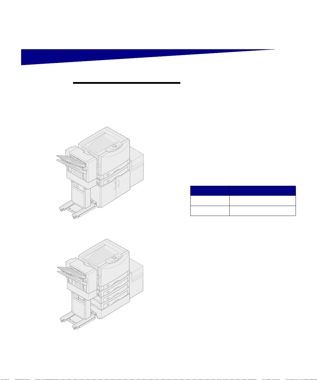
Printer with cabinet, high capacity feeder, and finisher
Your printer must be configured
Your Lexmark™ C910™ printer supports
an optional finisher that adds hole
punching, stapling, and offset functions
to the printer output capabilities.
Your finisher also increases output
capacity. You can stack up to 100 sheets
of 20 lb paper in bin 1 (the top bin) and
1000 sheets in bin 2 (the lower bin).
Depending on the finisher you have
chosen, you can punch 3 or 4 holes in
your print jobs. The number of holes and
their plac ement are set at the factory.
Finisher Part number
3-Hole 12N0784
4-Hole 12N0785
You can corner staple up to 30 sheets of
20 lb pap er. Stapled jobs exit face down
into bin 2.
If you select offsetting, your print jobs
exit into bin 2. Transparencies, card
stock, glossy paper, and labels exit only
into bin 1.
Printer with low profile printer stand, optional drawers,
high capacity feeder, and finisher
Introduction
1
Page 6
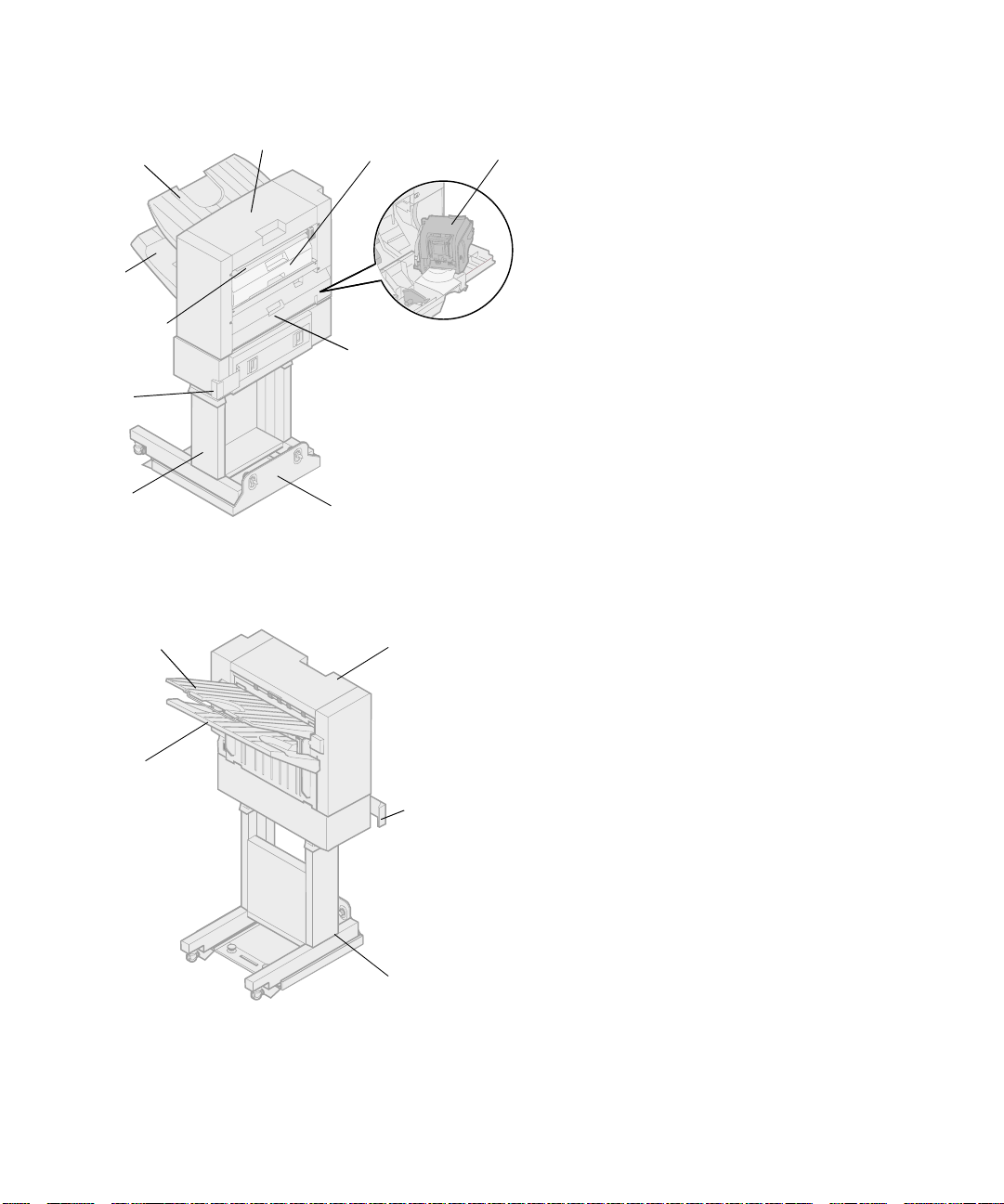
Bin 1
Bin 2
Entry guide
Latch
Top cover
Hole punch box
Stapler door
Stapler
Familiarize yourself with the names and
locations o f items o n the fr ont and r ear of
your new finisher. This will help you
during finisher setup.
To ensure your finisher is Energy Star
compliant, your printer controls the
power to the finisher.
Finisher stand
Bin 1
Bin 2
Guide rail
Front
Top cover
Latch
Finisher stand
Rear
2
Introduction
Page 7
Setup
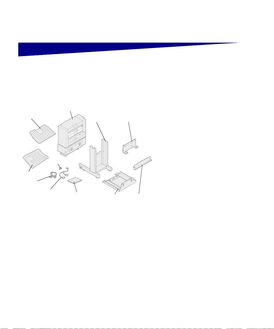
Output bin 1
Output bin 2
Interface cable
Y–Power cord
Unpacking the finisher
Finisher
Cable holder
Setup and
User’s Guide
Finisher stand
Guide rail
Docking plate
Guide rail
plate
1
Remove all items from the box
and unpack them.
2
Make sure you have all the
following items shown at left.
If any items are missing or damaged,
refer to the
Publications
Lexmark support phone number for your
country.
Save the carton and packing material in
case you need to repack the finisher.
Lexmark C910
CD for the designated
Setup
3
Page 8
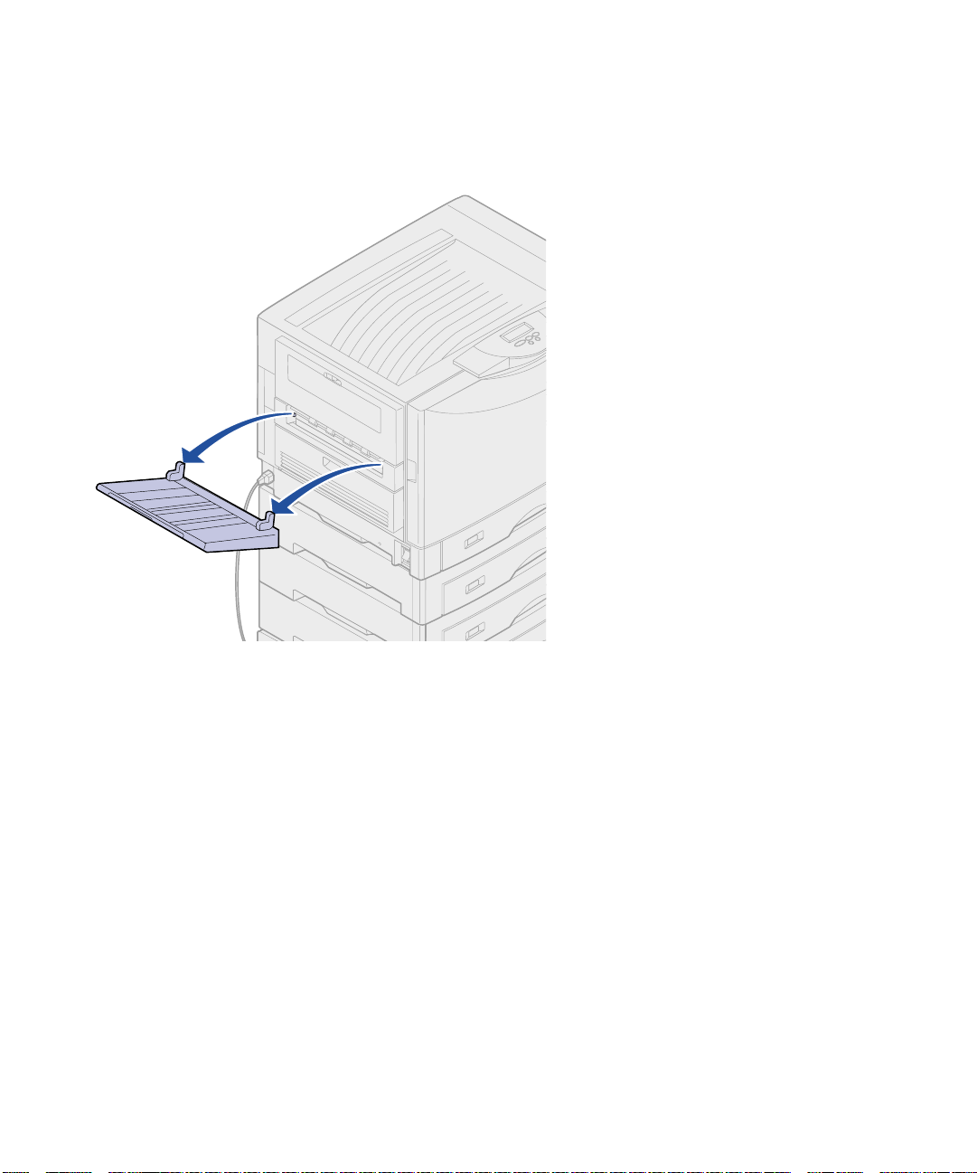
Attaching the docking
plate and guide rail
1
Lift the printer exit tray halfway
and remove.
You will not need the tray when
the finisher is attached. However,
you will need to move the finisher
and reinstall the tray to print
envelope sizes other than C5 or
B5.
4
Setup
Page 9
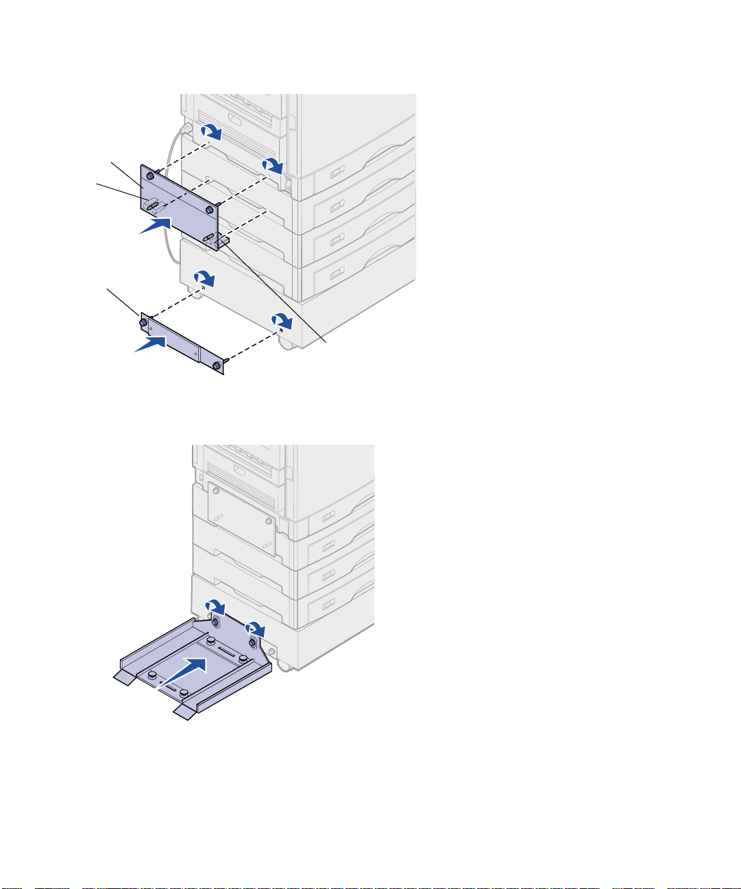
Docking plate
Tab
Guide rail plate
Tab
2
Insert the docking plate tabs into
the printer.
The tabs on the bottom of the
docking plate must be inserted
into the handholds on the printer
so the docking plate will be flush
against the printer.
3
Align the thumbscrews on the
docking plate with the holes in the
side of the printer.
4
Tighten the docking plate
thumbscrews.
5
Align the thumbscrews on the
guide rail plate with the holes in
the side of the printer cabinet or
stand.
6
Tighten the guide rail plate
thumbscrews.
7
Align the thumbscrews on the
guide rail with the holes in the
guide rail plate.
8
Tighten the guide rail
thumbscrews.
Setup
5
Page 10
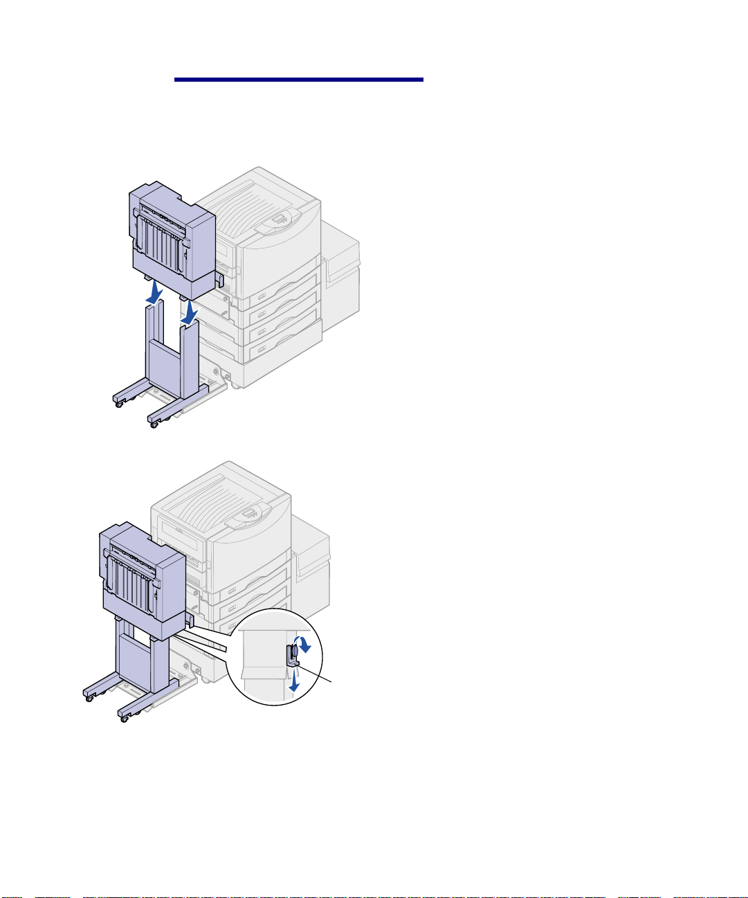
Docking plate pins
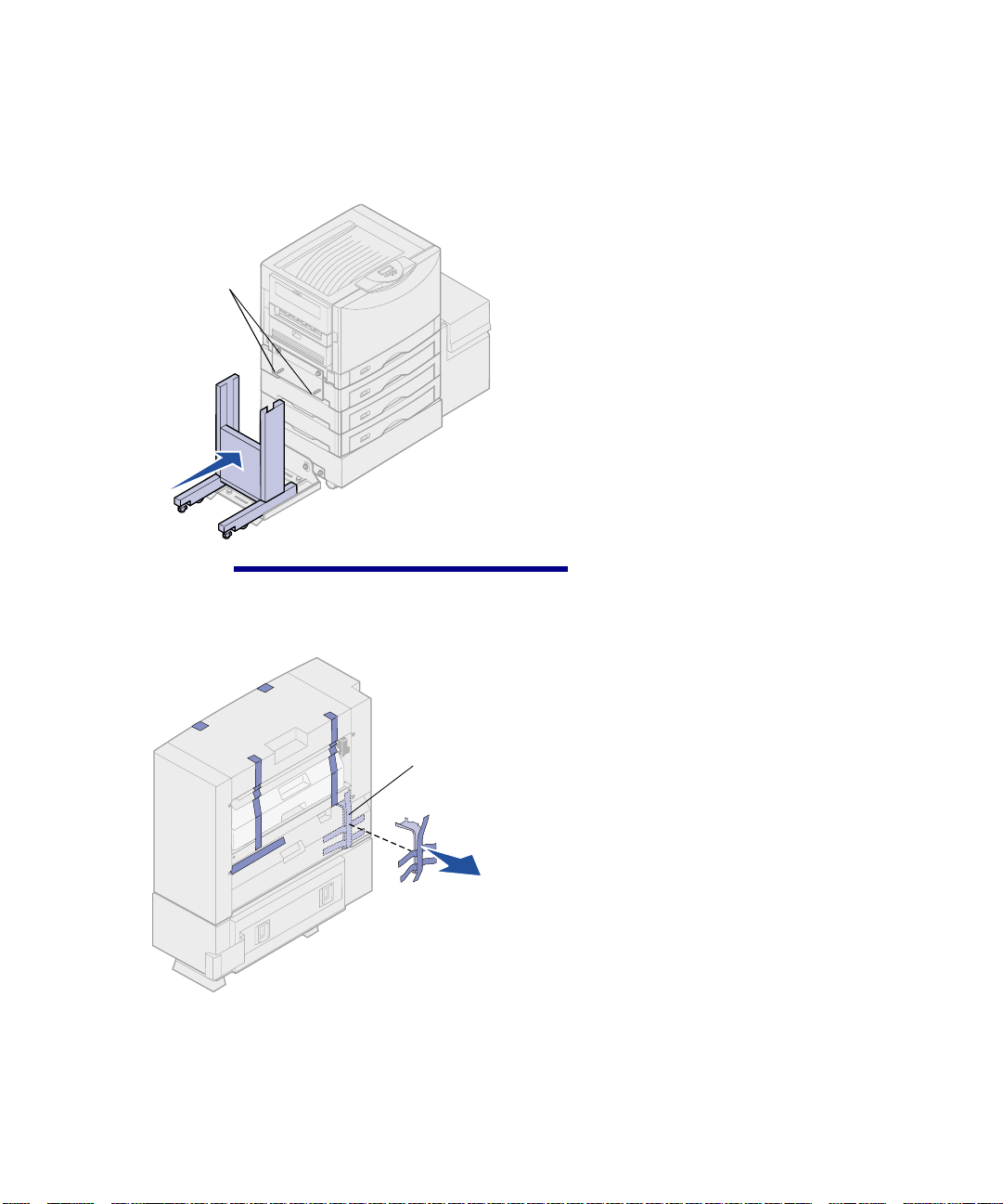
Combining the finisher
and stand
1
Roll the finisher stand onto the
guide rail.
Do not push the stand all the way
up against the printer.
CAUTION!
(42.2 Ibs).
The finisher weighs 19.7 kg
Metal shipping
bracket
2
Remove and discard all shipping
tape, packing material, and the
metal shipping bracket.
6
Setup
Page 11
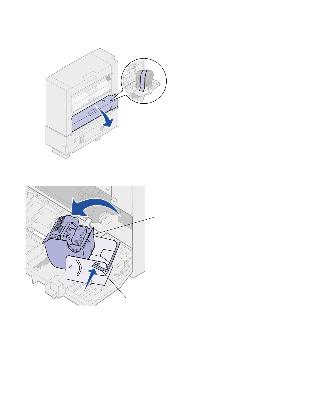
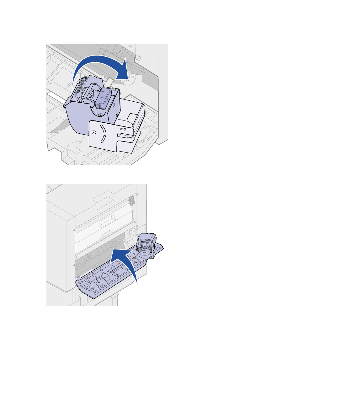
Stapler
3
Open the stapler door.
4
Remove all shipping tape and
packing material.
5
Lift the stapler locking lever.
6
Raise the stapler.
7
Remove all shipping tape and
packing material.
Stapler locking lever
Setup
7
Page 12
8
Close the stapler.
9
Close the stapler door.
8
Setup
Page 13
CAUTION!
finisher weighs 26.3 kg (56.9 Ibs) and
requires two people to lift it safely.
When assembled, the
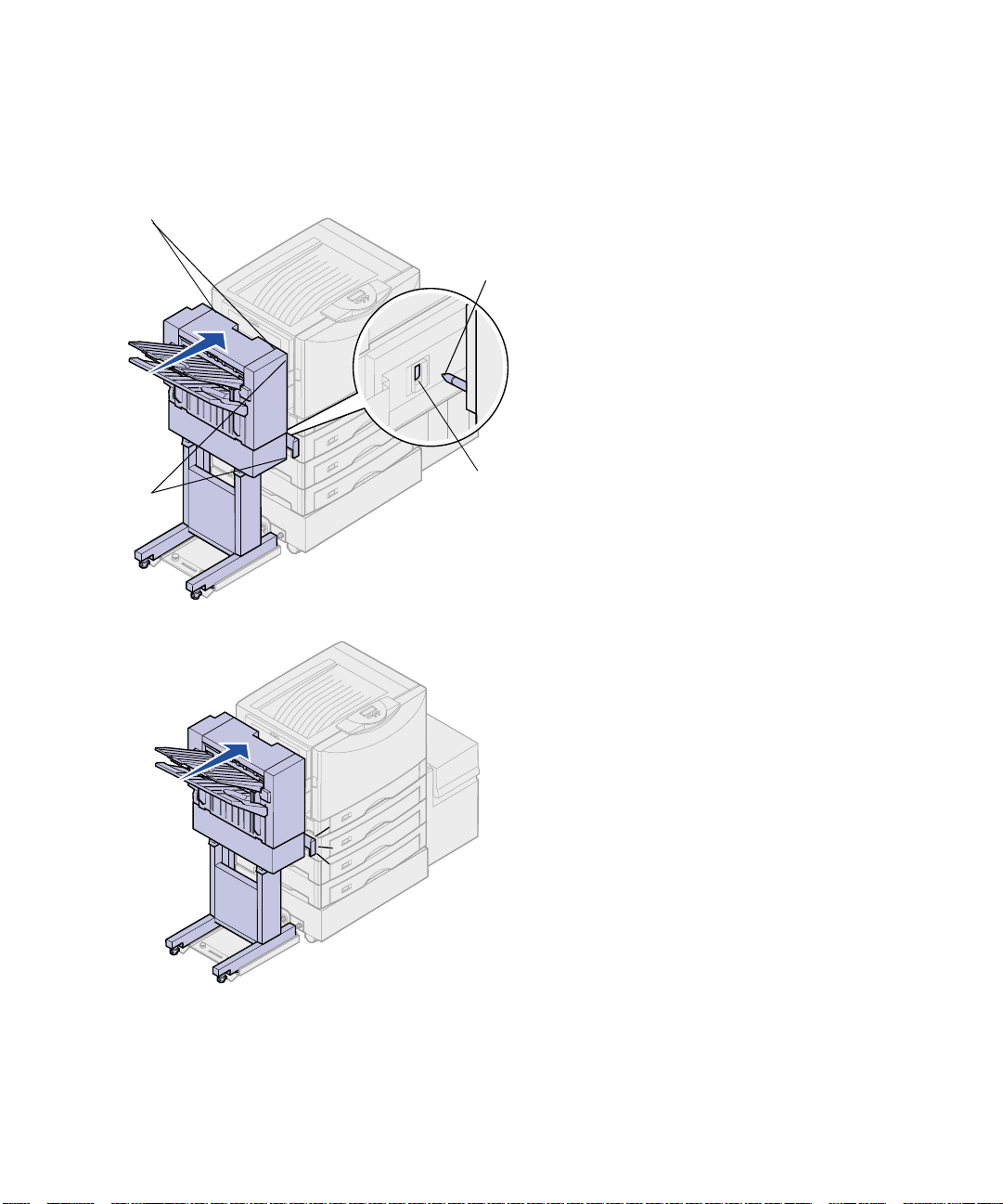
10
Align the two sockets on the
bottom of the finisher with the legs
of the finisher stand.
11
Lower the finisher onto the stand.
12
Remove both thumbscrew
spacers.
13
Tighten the two thumbscrews.
Thumbscrew
spacers
Setup
9
Page 14
Attaching the bins
Note:
and finisher stand are referred to as the
finisher.
Metal brackets
When assembled, the finisher
Slots
1
Align the slots on bin 2 with the
metal brackets on the rear of the
finisher.
2
Slide the bin down onto the metal
brackets until it is fully seated.
3
Align the tabs on bin 1 with the
slots on the rear of the finisher.
4
Lower the bin until it is fully
seated.
10
Setup
Page 15
Alignment marks
Aligning the finisher
and printer
Docking plate pin
The following three areas must align
properly to prevent paper jams.
1
The doc ki ng pl at e pi ns must enter
the holes in the finisher.
2
The space between the printer
and finisher must be the same at
the top and bottom of the finisher.
3
The alignment marks on top of the
finisher must align with the edges
of the cover on the side of the
printer.
Spacing
Hole in finisher
4
Roll the finisher toward the printer
until the finisher locks to the
docking plate pins.
You hear a
locks into position.
If the pi ns di d no t go i nto the ho les
in the finisher, see “Lowering or
raising the finisher” on page 12.
Otherwise, go to “Aligning the
sides of the finisher” on page 13.
click
when the finisher
Setup
11
Page 16
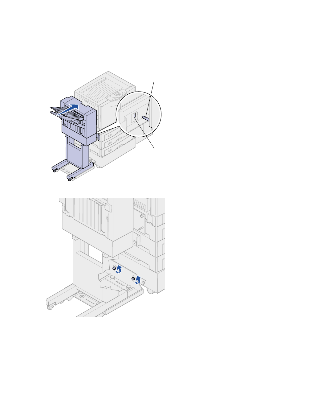
Lowering or raising the
finisher
Pin
Hole in finisher
Follow these instructions if the holes on
the finisher are above or below the pins
on the docking plate.
1
Determine if the pins are above or
below the holes in the finisher.
2
Loosen the guide rail
thumbscrews.
12
Setup
Page 17
3
Rotate the adjustment knobs as
needed to align the holes in the
finisher with the pins.
To raise the finisher, rotate the
adjustment knobs clockwise.
To lower the finisher, rotate the
adjustment knobs
counterclockwise.
4
Roll the finisher toward the printer
until the finisher locks to the
docking plate pins.
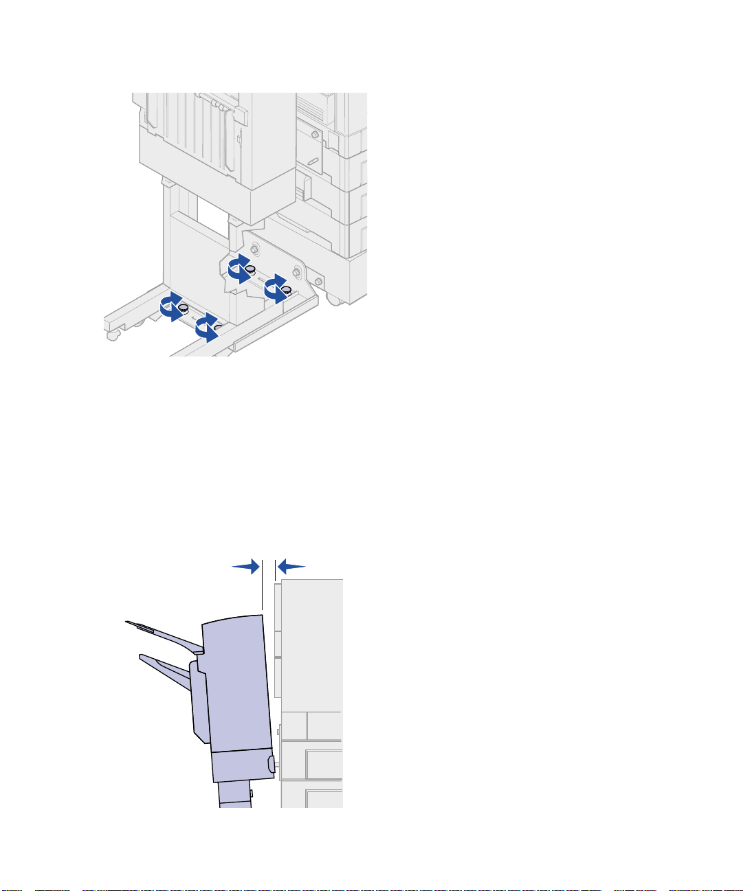
Aligning the sides of the
finisher
You hear a
locks into position.
If the pins go into the holes but the finisher did not lock to the pins, see “Aligning the sides of the finisher” on page 13. Otherwise, go to “Aligning the top of the finisher” on page 15.
Follow these instructions if the distance
between the finisher and printer is not
the same at the top and bottom.
click
when the finisher
Setup
13
Page 18
1
Loosen the guide rail
thumbscrews.
If you previously lowered or raised
the guide rail plate, the
thumbscrews will already be
loose.
2
Rotate the rear adjustment knobs
to equally align the top and bottom
of the finisher with the printer.
To move the top of the finisher
closer to the printer, rotate the
adjustment knobs clockwise.
14
Setup
To move the top of the finisher
away from the printer, rotate the
adjustment knobs
counterclockwise.
3
Roll the finisher toward the printer
until the finisher locks to the
docking plate pins.
You hear a
locks into position.
click
when the finisher
Page 19
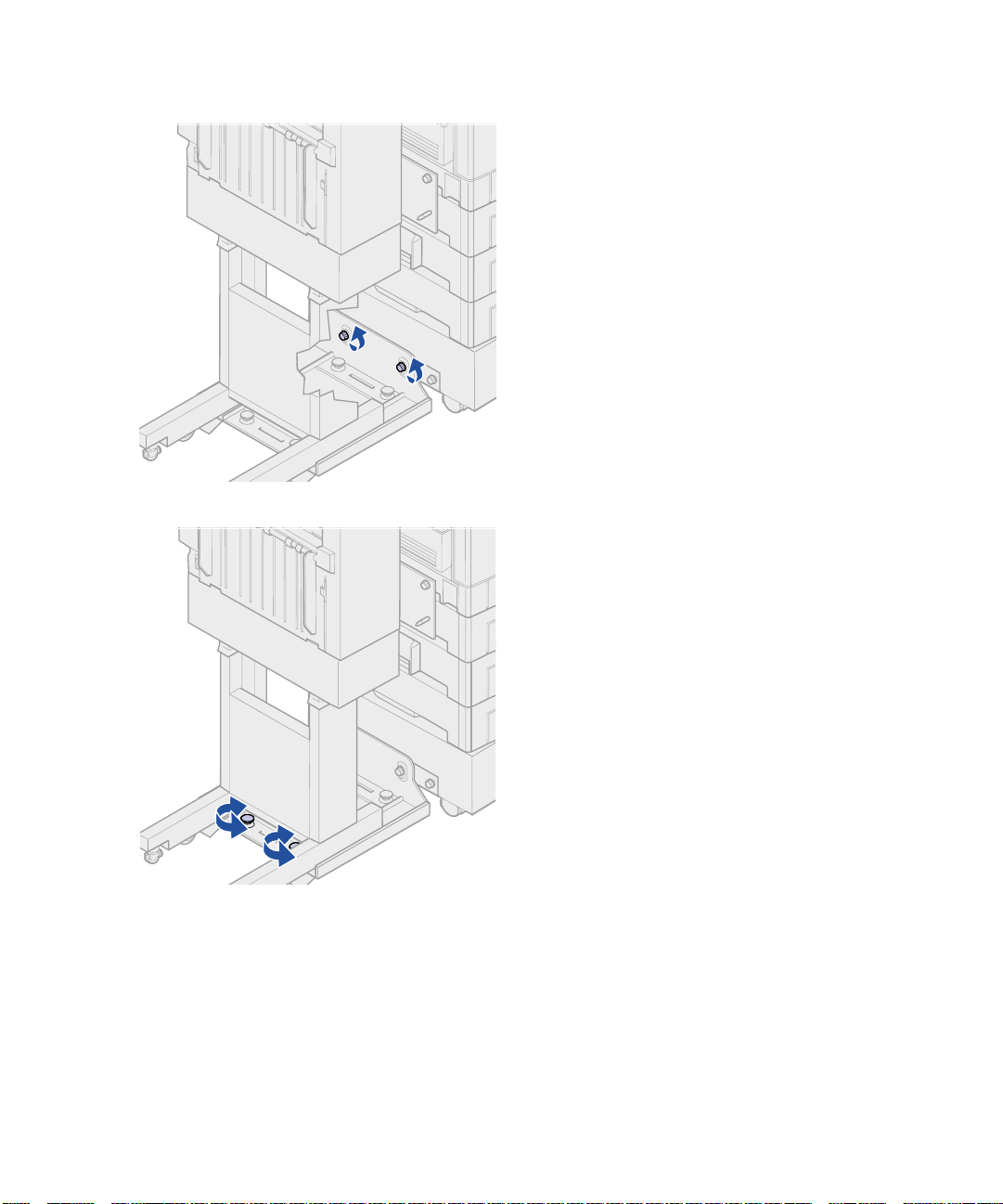
Aligning the top
of the finisher
Follo w t hese i nstruct ions i f the align ment
marks on top of the finisher are not
aligned with the edges of the cover on
the side of the printer.
Note:
finisher, recheck printer and finisher top
alignment.
Any time you move the printer or
1
Loosen the guide rail
thumbscrews.
If you made previous adjustments,
the thumbscrews will already be
loose.
2
Rotate the adjustment knobs as
needed to raise or lower the side
of the finisher.
To raise the finisher, rotate the
adjustment knobs clockwise.
To lower the finisher, rotate the
adjustment knobs
counterclockwise.
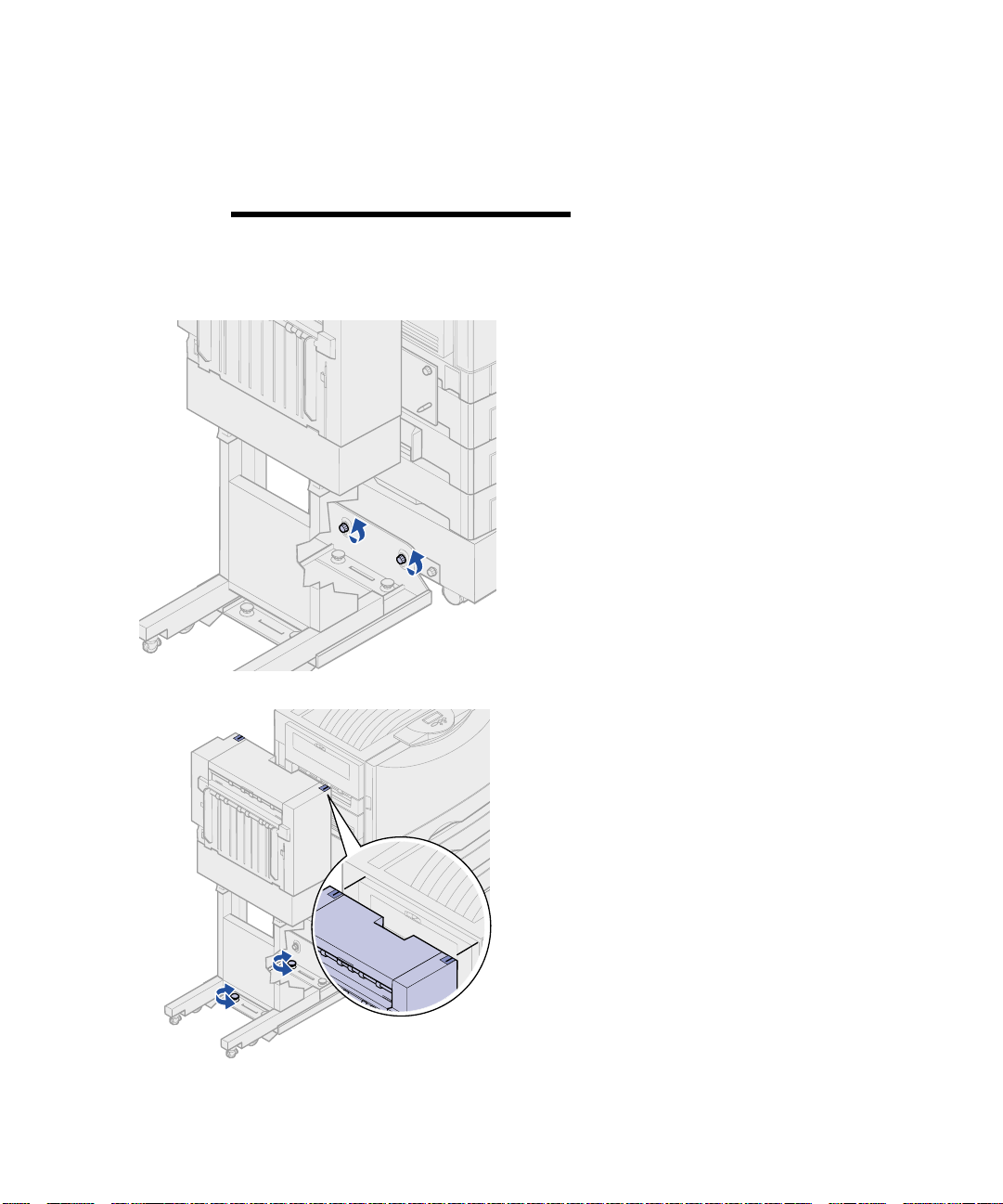
3
Tighten the guide rail
thumbscrews.
4
Roll the finisher toward the printer
until the finisher locks to the
docking pins.
You hear a
locks into position.
click
when the finisher
Setup
15
Page 20
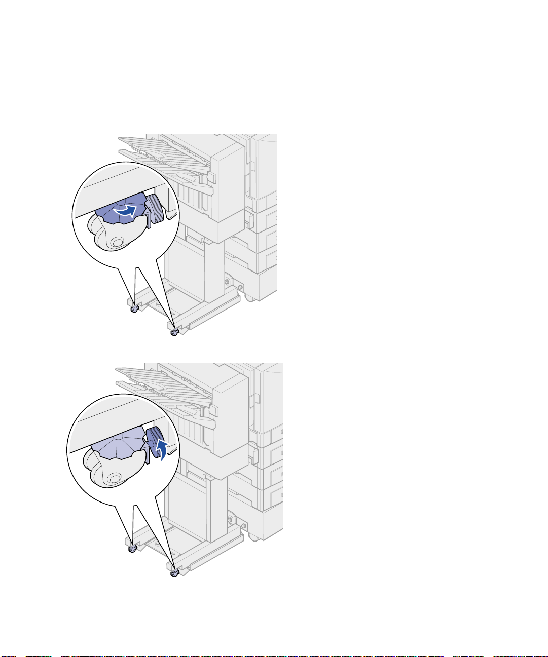
Adjusting the wheels Adjust the wheels on the end of the
finisher so the stand will remain aligned
when moved.
To adjust and lock the wheels:
1
Rotate the left and right upper
adjustment knobs on the rear
wheels until the wheels touch the
floor.
To lower the wheels, rotate the
adjustment knobs clockwise.
2
Turn the wheels until the locking
knobs are aligned with the finisher
base.
16
Setup
3
Rotate the locking knobs
counterclockwise until they
contact the finisher base.
Page 21
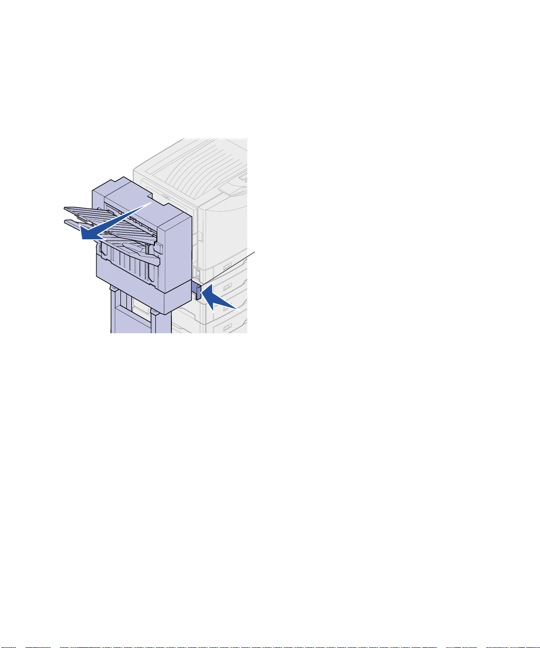
Attaching the cables Your finisher comes with an interface
cable and Y–
cable connects the finisher to the printer,
and the Y
power to the finisher and printer.
1
2
3
4
Latch
power cord. The interface
–
power cord provides electrical
Turn the printer off.
Push the latch in and hold it.
Roll the finisher away from the
printer.
Release the latch.
Setup
17
Page 22

Interface cable
CAUTION!
turned off before continuing.
Make sure the printer is
1
Plug the interface cable into the
bottom connector on the back of
the printer.
2
Tighten the thumbscrews.
3
Plug the interface cable into the
connector on the side of the
finisher.
The plug will be on a slight angle
when connected.
18
Setup
4
Tighten the thumbscrews.
Page 23

Power cable
1
Unplug the power cord from the
side of the printer.
Set the cord aside.
2
Plug the straight Y–power cord
connector into the socket on the
side of the finisher.
3
Plug the angled connector of the
Y–
power cord into the socket on
the side of the printer.
4
Connect the previously removed
printer power cord to the Y–
cord.
Setup
power
19
Page 24

5
Remove the protective paper from
the back of the cable holder.
6
Firmly press the adhesive-backed
cable holder onto the back of the
top optional drawer.
7
Place the finisher interface cable
and power cord into the cable
holder.
8
Close the cable holder .
9
Turn the printer on.
20
The finisher does not have a
power switch. Power is controlled
by the printer.
Setup
Page 25

Attaching the paper
jam label
Place the adhesive label that came with
your finisher over the left side of the
printer paper jam label inside the printer.
1
Open the front door.
2
Remove the protective paper as
shown.
Setup
21
Page 26

3
Firmly press the label as shown.
4
Close the front door.
22
Setup
Attaching the
finisher book sleeve
The adhesive sleeve that came with your
finisher is a handy place to store this
finisher book.
1
Remove the protective paper as
shown.
Page 27

2
Firmly press the sleeve onto the
area as shown.
Printing a menu
settings page
Note:
the operator panel and changing menu
settings, refer to your printer publications
CD.
UTILITIES MENU
1
Menu
For more information about using
Select
Go
3
5
2
Return
Stop
4
6
Print the menu settings page to review
the default printer settings and to verify
that printer options are installed
correctly.
1
Press
Utilities Menu, and then press
Select
2
Press
Menus, and then press
print the page.
The message Printing Menus
is displayed.
3
Verify the finisher is installed.
The finisher will be listed under
“Installed Features.” If it is not
listed, turn the printer off, unplug
the interface cable and power
cord, and then reinstall them.
4
Store this book in the sleeve.
until you see
Menu
.
until you see Print
Menu
Select
to
Setup
23
Page 28

Using finisher features
Output bins There are two output bins on your
finisher.
You can send the following types of
media to bin 1:
•
•
•
•
•
•
•
•
•
•
Plain paper
Bond paper
Card stock
Transparencies
Glossy paper
Labels
C5 and B5 envelopes
Letterhead
Preprinted paper
Colored paper
24
Using finisher features
You can only send A4 or letter paper to
bin 2. The following types of paper can
be sent to bin 2:
•
Plain paper
•
Bond paper
•
Letterhead
•
Preprinted paper
•
Colored paper
Page 29

Offsetting You can offset each print job or each
copy of a print job, making it easier to
separate the documents stacked in the
output bin.
The finisher stacks all offset print jobs in
bin 2. The amount of offset is
approximately 23 mm (0.9 in.).
You can select the following values from
the Finishing Menu using your printer
driver or the printer operator panel.
Value Output
None* Stacks all sheets directly on
Between
Copies
Between
Jobs
Values marked by an asterisk (*) are the
factory def au lt set t in gs.
top of each other.
Offsets each copy of a print
job.
Offsets each print job.
Using finisher features
25
Page 30

Stapling The stapler is located insi de the stap ler
door. You can corner staple 20 —28 lb
plain paper. The finisher stacks up to 30
stapled sets face down in bin 2.
The maximum number of sheets you can
staple is:
Paper weight Maximum
20 lb paper
30 sheets
24 lb paper
28 lb paper
Stapling more than the maximum number
of sheets may cause the stapler to jam.
You can select the following values from
the Finishing Menu using your printer
driver or the printer operator panel.
Value Output
Off*
On
Values marked by an asterisk (*) are the
factory def au lt set t in gs.
The message Load Staples appears
on the printer operator panel if the
stapler is empty or Insert Staple
Cartridge if the staple cartridge has
been removed. When the stapler has
been filled and reinstalled, the printer
clears the message.
Does not staple print jobs.
Staples each print job.
25 sheets
20 sheets
26
Using finisher features
Page 31

Latch
Use the following steps to remove the
stapler holder and add more staples:
1
Push the latch in and hold it.
2
Roll the finisher away from the
printer.
3
Release the latch.
4
Open the stapler door.
Stapler
Using finisher features
27
Page 32

Stapler
Stapler locking lever
5
Lift the stapler locking lever.
6
Rotate the stapler up.
7
Pull the staple holder from the
stapler.
28
Using finisher features
Page 33

8
Pull the empty staple cartridge
from the staple holder.
9
Discard the cartridge.
10
Remove the new staple cartridge
from its packaging.
Part number Description
11K3188 C910/T62x
Staple Cartridge
Note:
cartridge until after the cartridge has
been inserted into the holder.
Leave the tape on the staple
11
Insert the new cartridge.
12
Remove the tape from the
cartridge.
Using finisher features
29
Page 34

13
Insert the staple holder into the
stapler.
Push down until the staple holder
is fully seated.
14
Rotate the stapler to its closed
position.
30
Using finisher features
Page 35

15
Close the stapler door.
16
Roll the finisher toward the printer
until the finisher locks to the
docking pins.
You hear a
locks into position.
click
when the finisher
Using finisher features
31
Page 36

Hole punching Depending on the finisher you have, you
can punch 3 or 4 holes in your print jobs.
The finisher can stack hole punch print
jobs in bin 1 or bin 2. You cannot hole
punch transparencies, card stock, glossy
paper, or labels.
Value Output
Off*
Does not punch holes in
printed output.
On
Values marked by an asterisk (*) are the
factory def au lt set t in gs.
As the finisher punches holes, it deposits
discarded bits of paper in the hole punch
box. When the finisher has punched
15,000 sheets, the message Empty
Hole Punch Box appears on the printer
operator panel.
Use the following steps to empty the box:
1
2
3
Punches holes in every
printed page.
Push the latch in and hold it.
Roll the finisher away from the
printer.
Release the latch.
32
Latch
Using finisher features
Page 37

Handle
4
Lift the finisher entry guide
handle.
5
Lift the hole punch box, rotate the
bottom outward and then remove
it.
6
Release the handle.
7
Empty the box.
8
Lift the handle.
9
Place the top of the box in the
finisher and then rotate the bottom
of the box into the finisher.
10
Release the handle.
Using finisher features
33
Page 38

11
Roll the finisher toward the printer
until the finisher locks to the
docking pins.
You hear a
locks into position.
12
Check the printer operator panel
display.
If you emptied the box before the
Empty Hole Punc h Box
message appeared, press
until you see Supplies Menu on
the display and select Replace
Supplies, and then select Box
and select Replaced.
The Ready message appears.
click
when the finisher
Menu
34
Using finisher features
Page 39

Troubleshooting
This section helps you clear messages
that appear on the printer operator
panel, clear paper and stapler jams, and
resolve other finisher problems that may
occur.
Message Solution
Bin <x> Full
Close Finisher
Door
alternates with
Check Finisher
Installation
Empty Hole
Punch Box
Insert Hole
Punch Box
Load Staples
Remove the stack of paper from the specified bin. Press Go to clear the message and
continue printing.
Note: If you assigned the bin a name, the bin name is displayed instead of the bin
number.
Close the finisher top cover.
(or)
Make sure the finisher is flush against the printer.
You must empty the ho le pun ch box to continue printi ng. For instructions on emptying the
box, see “Hole punching” on page32. Press Go to clear the message and continue
printing.
The hole punch box is missing. Place the box in the finisher to clear the message.
You must replace the staple cartridge if you want to continue stapling. You can press Go
to clear the message and contin ue printin g witho ut stapl ing. F o r inst ructions on rep lacing
the staple cartridge, see “Stapling” on page 26.
Clearing finisher
messages
Messages appear on the printer operator
panel to inform you of the status of your
finisher. The following table e xplains how
to clear the messages.
Insert Staple
Cartridge
The staple holder is missing. Place the holder in the stapler to clear the message.
Troubleshooting
35
Page 40

Message Solution
210 Staple Jam
Check Area H
alternates with
Clear Staple Job
From Finisher
Requested Env
Not Supported
This message indicates a staple jam has occurred inside the finisher. Open the stapler
door, remove the paper from accumulator area, and clear the staple jam.
For information on removing the paper from the accumulator, see “Accumulator area” on
page 51. For information on clearing the staple jam, see “Clearing staple jams ” on
page 56.
This message indicates a request to print an envelope other than C5 or B5 was sent to
the printer with the finisher attached. The message displays for 5 seconds and then is
removed. The printer prints the information for the nonsupported envelope onto the print
media in tray 1.
Note: You receiv e thi s m es s age if you are trying to print envelope siz e s other than C5 or
B5 with the finisher attached to the printer. To print envelopes other than C5 or B5, see
“Printing envelopes” on page 38.
Solving other problems
Symptom Cause Solution
Paper frequently
jams in the finisher.
The finisher and printer are
misaligned.
The printer and finisher have
been moved.
Properly align the finisher with the printer. Refer to
“Aligning the sides of the finisher” on page13 and
“Aligning the top of the finisher” on page 15 for
instructions.
Use the following table to find
solutions to other problems with the
optional finisher.
The printer does not
print to the
requested output
bin.
The paper jam
message will not
clear.
36
Troubleshooting
You are trying to staple, hole
punch, or offset print jobs on
print media other than paper.
The finisher cables are not
connected properly.
Your printer driver and the
operator panel settings are
different.
You are trying to send a print
job to the wrong output bin.
The cover is not close d, the
finisher is not against the
printer, or there is paper
somewhere in the paper path .
Restrict use of the finisher to plain paper. You cannot
hole punch transparencies, card stock, labels, or
envelopes.
Check the cable connections. Refer to “Attaching the
cables” on page 17 for instructions on connecting the
finisher to the printer.
Make sure your printer driver is set to dir ect the output
to the bin you want.
Printer settings selected fro m a so ftw are ap plica tion or
driver override default settings selected from the
operator panel.
Card stock, transparencies, and hole punch jobs are
sent to bin 1. Stapled jobs are sent to bin 2.
Open and close the top cover and make sure the
finisher is locked onto the docking pins. Recheck the
finisher and printer for additional jams.
Page 41

Symptom Cause Solution
Pages are not stapled.
Punched holes are not
in the proper position.
You cannot print
requested envelopes.
You are trying to staple too
many sheets.
The staple cartridge is empty. Install a new staple cartridge. See “Stapling” on
The stapler is jammed. Check the stapler for a staple jam. See “Clearing
The printer and finisher are not
aligned properly.
You hole punched a printed job
on different finishers.
You are trying to print envelope
sizes other than C5 or B5 with
the finisher attached to the
printer.
Reduce the number of pages in the staple job.
The finisher can staple up to 30 sheets of 20 lb paper.
If you attempt to staple a larger stack of paper, the
finisher ejects the stack without stapling it.
page 26 for instructions.
staple jams” on page 56 for instructions.
Align the top of the finisher with the printer. See
“Aligning the top of the finisher” on page 15 for
instructions.
Move the alignment of the finisher to compensate for
the hole punch diffe r en ce. See “Hole punch
adjustment” on page 44 for instructions.
Move the finisher away from the printer. Reinstall the
printer exit tray. Turn the printer off. Wait 15 seconds
and turn the printer on. Resend the envelope print job.
Troubleshooting
37
Page 42

Printing envelopes You can print C5 or B5 envelopes on
your printer and send them to bin 1. If
you try to print envelopes other than C5
or B5 and have the finisher attached to
the printer, you receive the Requested
message.
Latch
Env Not Supported
The message displays for 5 seconds and
then is removed. The printer prints the
information for the nonsupported
envelope onto the print media in tray 1.
To print envelopes other than C5 or B5:
1
Push the latch in and hold it.
2
Roll the finisher away from the
printer.
3
Release the latch.
38
Troubleshooting
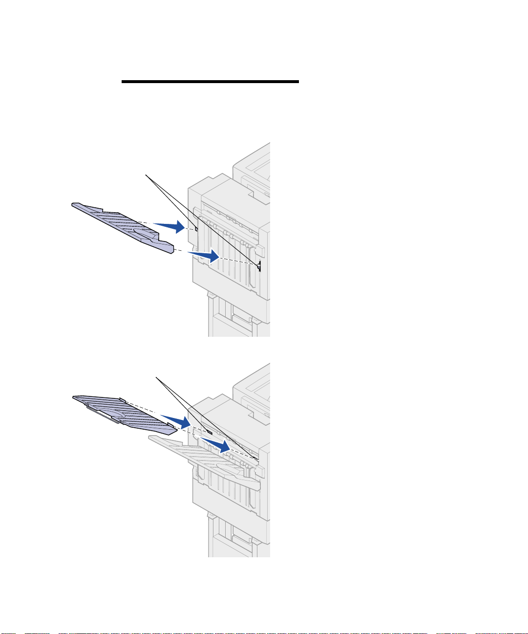
Page 43

4
Align the holes on the exit tray
tabs with the pins on the side of
the printer.
5
Attach the printer exit tray to the
printer.
6
Turn the printer off.
Troubleshooting
39
Page 44

7
Loosen the interface cable
thumbscrews.
8
Unplug the interface cable from
the connector on the side of the
finisher.
9
Turn the printer on.
10
Resend the envelope print job to
the printer.
When you are finished printing
envelopes complete the following steps:
40
Troubleshooting
Page 45

1
Lift the printer exit tray halfway
and remove.
2
Turn the printer off.
Troubleshooting
41
Page 46

3
Plug the interface cable into the
connector on the side of the
finisher.
The plug will be on a slight angle
when connected.
4
Tighten the thumbscrews.
5
Turn the printer on.
42
Troubleshooting
Page 47

6
Roll the finisher toward the printer
until the finisher locks to the
docking plate pins.
You hear a
locks into position.
click
when the finisher
Troubleshooting
43
Page 48

Hole punch adjustment You can adjust the hole punch alignment
by approximately 4 mm (
adjustment is useful when you want to
center the punched holes onto the paper
or if you hole punched a printed job on
different finishers.
3
/16 in.). This
Note:
used for both three and four hole punch
finishers.
The following procedures are
1
Verify the alignment of the printer
and finisher is correct.
If the alignment is not correct, see
“Aligning the top of the finisher” on
page 15 for instructions, and then
print and hole punch another
sheet of paper and see if an
adjustment is needed.
If an adjustment is needed,
continue with step 2.
2
Using a sheet of paper previously
punched from the finisher, fold the
paper so the bottom punched hole
is aligned with the top punched
hole.
Bottom edge is
below top edge
44
Troubleshooting
Bottom edge is
above top edge
3
Determine if the edge of the
bottom of the page is below or
above the top edge of the page.
Page 49

4
Loosen the guide rail
thumbscrews.
Note:
knobs more than three complete turns
from their starting position. Adjustments
greater than three turns may cause
paper jams.
Do not move the adjustment
5
Rotate both adjustment knobs as
shown, the same amount to raise
or lower the side of the finisher.
A half turn of the knob moves the
position of the hole approximately
one third to one half the distance
of the punched hole.
To move the bottom of the paper
down, rotate the knobs clockwise.
To move the bottom of the paper
up, rotate the knobs
counterclockwise one quarter
turn.
Troubleshooting
45
Page 50

6
Tighten the guide rail
thumbscrews.
7
Print and punch another piece of
paper.
8
Repeat steps 2 and 3. If the holes
are not aligned repeat steps 3
through 8.
Clearing paper jams By carefully selecting and loading paper,
you can avoid most paper jams. For
information on avoiding paper jams, refer
to the
Lexmark C910 Publications
CD.
200 Paper Jam
Check Area I
200 Paper Jam
Check Area H
46
Troubleshooting
200 Paper Jam
Check Area G
When a finisher paper jam occurs, the
200 Paper Jam Check Area <x>
message appears on the printer operator
panel. The illustration at the left identifies
the areas you must check to clear a
finisher paper jam. Refer to your printer’s
Quick Reference
information about clearing jams in the
printer.
You must clear the jam and then press
to resume printing. The Jam
Go
Recovery menu item in the Setup Menu
determines whether the printer reprints
the jammed page. Refer to your printer’s
publications CD for information about the
Jam Recovery menu item.
or publications CD for
Page 51

To clear:
Jam message See page
Check Area G
Check Area G
Check Area H
Check Area I
This message indicates a jam in the
input area of the finisher. To clear
area G:
1
Open the finisher top cover and
remove any jams.
2
Close the top cover.
3
Press Go.
You must clear any printer paper
jams before the printer will resume
printing. For instructions on
clearing printer paper jams, refer
to your printer’s
or publications CD.
47
48
53
Quick Reference
Troubleshooting
47
Page 52

Check Area H
Latch
This message indicates a paper jam
inside the finisher. You need to check
both the upper access area and
accumulator area. To clear area H:
1
Push the latch in and hold it.
2
Roll the finisher away from the
printer.
3
Release the latch.
4
Remove any jams from the
finisher entry guide.
48
Entry guide
Troubleshooting
Page 53

Handle
Upper access area
1
Lift the finisher entry guide
handle.
2
Lift the hole punch box, rotate the
bottom outward and then remove
it.
3
Release the handle.
4
Lift the jam access cover.
Jam access
cover
Troubleshooting
49
Page 54

Knob
5
Remove any jams from the
finisher.
Rotate the knob to move the
paper into the access cover area.
6
Release the jam access cover .
7
Lift the finisher entry guide
handle.
8
Place the top of the box in the
finisher, and then rotate the
bottom of the box into the finisher.
50
Troubleshooting
9
Release the handle.
Page 55

Accumulator area
1
Open the stapler door.
2
Remove any jams from the
accumulator.
Rotate the accumulator knob
counterclockwise to move the
paper down.
Accumulator
knob
Troubleshooting
51
Page 56

3
Close the stapler door.
4
Roll the finisher toward the printer
until the finisher locks to the
docking pins.
You hear a
locks into position.
5
Press Go.
You must clear any printer paper
jams before the printer will resume
printing. For instructions on
clearing printer paper jams, refer
to your printer’s
or publications CD.
click
when the finisher
Quick Reference
52
Troubleshooting
Page 57

Check Area I
This message indicates a jam in one of
the output areas of the finisher. To clear
area I:
1
Open the finisher top cover and
remove any jams.
2
Close the top cover.
3
Push the latch in and hold it.
4
Roll the finisher away from the
printer.
Latch
5
Release the latch.
Troubleshooting
53
Page 58

6
Open the stapler door.
7
Remove any jams from the
accumulator.
Rotate the accumulator knob
counterclockwise to move the
paper down.
54
Troubleshooting
Accumulator
knob
Page 59

8
Close the stapler door.
9
Roll the finisher toward the printer
until the finisher locks to the
docking pins.
You hear a
locks into position.
10
Press Go.
You must clear any printer paper
jams before the printer will resume
printing. For instructions on
clearing printer paper jams, refer
to your printer’s
or publications CD.
click
when the finisher
Quick Reference
Troubleshooting
55
Page 60

Clearing staple jams If your print job is not stapled, make sure
you have selected the Staple value from
the Finishing Menu of your printer driver
or the printer operator panel.
If the correct menu value has been
selected and the job does not staple, or
you received a 210 Staple Jam Check
Area H message, use the following
steps to remove and clear the stapler:
1
Push the latch in and hold it.
2
Roll the finisher away from the
printer.
3
Release the latch.
Latch
4
Open the stapler door.
56
Stapler
Troubleshooting
Page 61

Stapler
Stapler locking lever
5
Lift the stapler locking lever.
6
Rotate the stapler up.
7
Remove the staple holder from
the stapler.
Troubleshooting
57
Page 62

8
Lift the staple holder arm.
9
Remove any staples from the end
of the staple holder.
58
Troubleshooting
10
Lower the staple holder arm until it
locks to the staple holder.
Page 63

11
Insert the staple holder into the
stapler.
Push the staple holder down until
it is fully seated.
12
Rotate the stapler to its closed
position.
Troubleshooting
59
Page 64

13
Close the stapler door.
14
Roll the finisher toward the printer
until the finisher locks to the
docking pins.
You hear a
locks into position.
15
Press Go.
click
when the finisher
60
Troubleshooting
Page 65

Electronic emission notices
Federal Communications
Commission (FCC)
compliance information
statement
Note:
FCC regulations on el ectromagneti c
interference f or a Class A computi ng
device, use a properly shielded and
grounded cable. Use of a substitute
cable not properly shielded and
grounded ma y res ult in a v iolation of
FCC regulations.
To assure compliance with
Industry Canada
compliance statement
Avis de conf ormit é aux
normes d’Industrie
Canada
This finisher h as been teste d and found to comply with the l imits for a Class A
digital device, pursuant to Part 15 of the FCC Rules. Operation is subject to
the following two conditions: (1) this device may not cause harmful
interference, and (2) this device must accept any interference received,
including interference that may cause undesired operation.
The FCC Class A limits are designed to provide reasonable protection
against harmful interf erence when the e quipment is op erat ed in a comme rcial
environment. This equipment generates, uses, and can radiate radio
frequency energy and, if not installed and used in accordance with the
instruction manual, may cause harmful interference to radio communications.
Operation of this equipment in a residential area is likely to cause harmful
interferenc e, in which case the u ser will b e requ ired to co rrect the interf erence
at their own expense.
The manufacturer is not responsible for any radio or television interference
caused by using other than recommended cables or by unauthorized
changes or modifications to this equipment. Unauthorized changes or
modifications could void the user's authority to operate this equipment.
This Class A digital apparatus meets all requirements of the Canadian
Interferenc e-C au sing Equi pm ent Regulations.
Cet appareil numérique de la classe A respecte toutes les exigences du
Règlement sur le matériel brouilleur du Canada.
European Community
(EC) directives
conformity
This product is in conformity with the protection requirements of EC Council
directives 89/336/EEC and 73/23/EEC on the approximation and
harmonization of the laws of the Member States relating to electromagnetic
compatibility and safety of electrical equipment designed for use within
certain voltage limits.
Electronic emission notices
61
Page 66

Warning! When a print server is
installed, this is a Class A product.
In a domestic environment, this
product may cause radio
interference, in which case, the user
may be required to take adequate
measures.
CISPR 22 WARNING: This is a Class A product. In a domestic environment, this
A declaration of conformity with the requirements of the directives has been
signed by the Director of Manufacturing and Technical Support, Lexmark
International, S.A., Boigny, France.
This product satis fies t he Class A limi ts of EN 5502 2 a nd sa f ety require ments
of EN 60950.
product may cause radio int erfere nce, in whic h case the user ma y be required
to take adequate measures.
AVERTISSEMENT: Ce produit appartient à la classe A. Dans un
environnement résidentiel, ce produit risque de provoquer des interférences
radio, auquel cas l'utilisateur devra prendre les mesures adéquates.
AVVERTENZA: Questo prodotto appartiene alla Classe A. In ambiente
domestico, questo prodotto può causare interferenze radio, nel qu al caso è
necessario adottare adeguate precauzioni.
W ARNUNG: Bei diesem Gerät handelt es sich um ein Produkt der Klasse A.
In Wohngebieten kann dieses Gerät Störungen des Radio- und
Fernsehempfangs verursachen. Der Benutzer muß in diesem Fall geeignete
Maßnahmen ergreifen.
ADVERTENCIA: Este es un producto de Clase A. En un entorno doméstico,
este producto puede causar interferencias de radio, en cuyo caso, se
solicitará al usuario que adopte las medidas oportunas.
Japanese VCCI notice
The United Kingdom
Telecommunications Act
1984
62
Electronic emission noti ce s
AVISO: Este produto pertence à classe A. Em um ambiente doméstico, ele
pode causar interferências em transmissões de rádio. Nesse caso, será
necessário que o usuário adote as medidas adequadas.
This apparatus is ap proved under the approval number N S/G /12 34/J /10 00 03
for the indirect connections to the public telecommunications systems in the
United Kingdom.
Page 67

Index
A
alignment, hole punch 44
attaching
bins 10
cables 17
docking plate 4
finisher 11
finisher book sleeve 22
finisher stand 9
guide rail 4
guide rail plate 4
paper jam label 21
B
bins
attaching 10
capacities 1
messages 35
output 24
C
cabinet 1
cables
interface 18
power 19
CD
publications 3
Clear Staple Job From Finisher 36
clearing
messages 35
paper jams 46
stapler jam 56
cord, power 19
D
docking plate 5
E
emptying the hole punch box 32
Energy Star 2
envelope printing 38
F
FCC emissions information ii
finisher
aligning 11
stand 9
view, front and rear 2
G
guide rail 4
guide rail plate 4, 5
Index
63
Page 68

H
O
hole punching 32
alignment 44
capacities 32
emptying the hole punch box 32
I
installation verification 23
installing
bins 10
staple cartridge 26
introduction 1
J
jam
label 21
paper 46
stapler 56
L
label, paper jam 21
Load Staples 26
offsetting 25
options
drawers 1
low profile printer stand 1
printer cabinet 1
other problems 36
output bins
attaching 10
capacities 1
supported paper types 24
P
paper jam label 21
paper jams 46
paper weights 26
printer stand 1
printing envelopes 38
problems
finisher 36
frequent jams 36
other problems 36
solving 36
publications CD 3
M
maximum stapled sheets 26
menu settings page 23
messages 35
210 Staple Jam 36
Bin <x> Full 35
Check Finisher Installation 35
Close Finisher Door 35
Empty Box 32
Empty Hole Punch Box 35
Insert Hole Punch Box 35
Insert Staple Cartridge 35
Load Staples 26, 35
Requested Env Not Supported 35
64
Index
R
replacing a staple cartridge 26
S
safety information
located on inside front cover
sleeve, finisher book 22
solving problems 36
stand
finisher 9
printer 1
staple cartridge, replacing 26
staple jam 56
stapling 26
Page 69

T
troubleshooting 35
V
verify finisher installation 23
Index
65
Page 70

P/N 12N0467
E.C. 2N0016
Lexmark and Lexmark with diamond de sign are trademarks of Lexmark International, Inc.,
registered in the United States and/or other countries.
© 2002 Lexmark International, Inc.
740 West New Circle Road
Lexington, Kentucky 40550
www.lexmark.com
 Loading...