

Page 1

Revised: April 6, 2007
Lexmark OptraTM C710
• Table of Contents
•Start Diagnostics
5016-001
• Safety and Notices
• Trademarks
•Index
Lexmark and Lexmark with diamond
design are trade ma rks of Lexmark
International, Inc., registered in the
United States and/or ot her countries.
Page 2

T
T
t
©
A
T
5016-001
Edition:A pril 6, 2007
he following paragraph does not apply to any country where such provisions are
inconsistent with local law: LEXMARK INTERN ATIONAL, INC. PROVIDES THIS
PUBLICATION “AS IS” WITHOUT WARRANTY OF ANY KIND , EITHER EXPRESS OR
IMPLIED, INCLUDING , BUT NOT LIMITED TO, THE IMPLIED WARRANTIES OF
MERCHANT ABI LITY OR FITNESS FOR A PARTICULAR PURPOSE. Some states do not
allow disclaimer of ex press or implied warranties in certain transactions ; therefore, this
statement may not apply to you.
his publication could include technical inaccuracies or typographical errors. Changes are
periodically made to the information herein; thes e changes will be incorporated in later
editions. Improvements or changes in the products or the programs describ ed may be
made at any time.
Comments may be addressed to Lexma rk International, Inc., Department D22A/032-2,
740 West New Circle Road, Lexington, Kentucky 40550, U.S.A or e-mail at
ServiceInfoAndTraining@Lexmark.com. Lexmark may use or distribute any of the
information you supp ly in any way it believes appropriate without incurring any obligation
o you.
Lex mark an d O ptra are tr ad ema rk s of Lexmark Internatio na l, I nc. , r eg is ter ed in the U nit ed
States and/or other countries.
Color Jetprinter is a trademark of Lexmark International, Inc.
Other tradema rks are the property of their respectiv e owners.
Copyright Lexmark International, Inc. 2000, 2005.
ll rights reserved.
UNITED STATES GOVERNMENT RESTRICTED RIGHTS
his software and documentation are provided with RESTRICTED RIGHTS. Use,
duplic ation or disclosure by the Govern ment is subject to restrictions as set forth in
subparagraph (c)(1)(ii) of the Rights in Technical Data and Comput er Software cla use at
DFARS 25 2.227-7 013 and in applicable FAR provisions: Lexmark Int ernational, Inc.,
Lexington, KY 40550.
P/N: 12G6111
Page 3

5016-001
Table of Contents
Notices and Safety Information. . . . . . . . . . . . . . . . . . . . . . . . . . . . ix
Laser Notices . . . . . . . . . . . . . . . . . . . . . . . . . . . . . . . . . . . . . . . . . . . ix
General Information . . . . . . . . . . . . . . . . . . . . . . . . . . . . . . . . . . . . 1-1
Models . . . . . . . . . . . . . . . . . . . . . . . . . . . . . . . . . . . . . . . . . . . . . . . 1-2
Standard Features . . . . . . . . . . . . . . . . . . . . . . . . . . . . . . . . . . . . . . 1-2
Tools Required For Service . . . . . . . . . . . . . . . . . . . . . . . . . . . . . 1-6
Options . . . . . . . . . . . . . . . . . . . . . . . . . . . . . . . . . . . . . . . . . . . . . . . 1-7
Operational Theory . . . . . . . . . . . . . . . . . . . . . . . . . . . . . . . . . . . . . . 1-8
Interlock Mechanism . . . . . . . . . . . . . . . . . . . . . . . . . . . . . . . . . . 1-8
Sheet Bypass Paper Feed Unit . . . . . . . . . . . . . . . . . . . . . . . . . . 1-9
Paper Feed Unit. . . . . . . . . . . . . . . . . . . . . . . . . . . . . . . . . . . . . 1-11
Second Paper Feed Unit (Optional Paper Trays) . . . . . . . . . . . 1 -13
Drive Block. . . . . . . . . . . . . . . . . . . . . . . . . . . . . . . . . . . . . . . . . 1-17
Contact Cam . . . . . . . . . . . . . . . . . . . . . . . . . . . . . . . . . . . . . . . 1 -18
Coupling Unit . . . . . . . . . . . . . . . . . . . . . . . . . . . . . . . . . . . . . . . 1 -19
Carriage Unit . . . . . . . . . . . . . . . . . . . . . . . . . . . . . . . . . . . . . . . 1-21
Toner Cartridge Unit. . . . . . . . . . . . . . . . . . . . . . . . . . . . . . . . . . 1 -22
Intermediate Tra ns fer Unit . . . . . . . . . . . . . . . . . . . . . . . . . . . . . 1-24
Fuser/Paper Exit Unit. . . . . . . . . . . . . . . . . . . . . . . . . . . . . . . . . 1 -27
Detecting New Cleaning Unit. . . . . . . . . . . . . . . . . . . . . . . . . . . 1-28
Duplex Unit (Option). . . . . . . . . . . . . . . . . . . . . . . . . . . . . . . . . . 1 -29
Diagnostic Information . . . . . . . . . . . . . . . . . . . . . . . . . . . . . . . . . 2-1
Start . . . . . . . . . . . . . . . . . . . . . . . . . . . . . . . . . . . . . . . . . . . . . . . . . 2-1
Service Error Codes . . . . . . . . . . . . . . . . . . . . . . . . . . . . . . . . . . . . . 2-2
User Status Messages . . . . . . . . . . . . . . . . . . . . . . . . . . . . . . . . . . . 2-7
User Attendance Messages . . . . . . . . . . . . . . . . . . . . . . . . . . . . . . 2 -13
Symptom Tables . . . . . . . . . . . . . . . . . . . . . . . . . . . . . . . . . . . . . . 2 -28
Base Printer Symptom Table. . . . . . . . . . . . . . . . . . . . . . . . . . . 2-28
Covers Interlock Symptom Table . . . . . . . . . . . . . . . . . . . . . . 2 -29
Duplex Unit Symptom Table . . . . . . . . . . . . . . . . . . . . . . . . . . . 2 -29
Operator Panel Symptom Table . . . . . . . . . . . . . . . . . . . . . . . 2-30
Paper Feed Symptom Table . . . . . . . . . . . . . . . . . . . . . . . . . . . 2-30
Paper Tray Options Symptom Table . . . . . . . . . . . . . . . . . . . . . 2-31
Power Symptom Table . . . . . . . . . . . . . . . . . . . . . . . . . . . . . . . 2-31
Print Quality Symptom Table . . . . . . . . . . . . . . . . . . . . . . . . . . . 2-32
Service Checks . . . . . . . . . . . . . . . . . . . . . . . . . . . . . . . . . . . . . . . 2 -34
iii
Page 4

5016-001
Base Printer Servic e Checks . . . . . . . . . . . . . . . . . . . . . . . . . . . . . .2-35
Bypass Tray (Multipurpose Tray) Service Check . . . . . . . . . . . .2-35
Carriage Unit Service Check. . . . . . . . . . . . . . . . . . . . . . . . . . . .2-39
Coupling Unit Service Check. . . . . . . . . . . . . . . . . . . . . . . . . . . .2-42
Cover Interlock Service Check . . . . . . . . . . . . . . . . . . . . . . . . . .2-45
Developer/Paper Feed Motor Service Check . . . . . . . . . . . . . . .2-48
Erase Lamp Service Check. . . . . . . . . . . . . . . . . . . . . . . . . . . . .2-50
Fuser Cold Service Check. . . . . . . . . . . . . . . . . . . . . . . . . . . . . .2-51
Fuser Drive and Contact Cam System Service Check . . . . . . . .2-53
Fuser Hot Service Check . . . . . . . . . . . . . . . . . . . . . . . . . . . . . .2-57
High Voltage Leakage Detect Service Check . . . . . . . . . . . . . . .2-58
ITM Drive Service Check. . . . . . . . . . . . . . . . . . . . . . . . . . . . . . .2-60
Main Fan Service Check. . . . . . . . . . . . . . . . . . . . . . . . . . . . . . .2-62
New Toner Cartridge Detection Service Check. . . . . . . . . . . . . .2-63
Operator Panel Service Check . . . . . . . . . . . . . . . . . . . . . . . . . .2-64
Operator Panel Buttons Service Check. . . . . . . . . . . . . . . . . . . .2-65
OPC Drive Service Check. . . . . . . . . . . . . . . . . . . . . . . . . . . . . .2-66
Paper Exit Sensor Service Check . . . . . . . . . . . . . . . . . . . . . . . .2-67
Paper Feed Service Check . . . . . . . . . . . . . . . . . . . . . . . . . . . . .2-68
Paralle l Po r t Se r vice Check. . . . . . . . . . . . . . . . . . . . . . . . . . . . .2-71
Power Service Check . . . . . . . . . . . . . . . . . . . . . . . . . . . . . . . . .2-72
Printhead Service Check. . . . . . . . . . . . . . . . . . . . . . . . . . . . . . .2-77
Print Quality Service Checks . . . . . . . . . . . . . . . . . . . . . . . . . . . . . .2-79
Print Qualit y Init ia l S er v ic e Check . . . . . . . . . . . . . . . . . . . . . . . .2-79
All Black or Color Page Service Check. . . . . . . . . . . . . . . . . . . .2-80
All Blank Page Service Check. . . . . . . . . . . . . . . . . . . . . . . . . . .2-81
Background Service Check. . . . . . . . . . . . . . . . . . . . . . . . . . . . .2-82
Black, Color Lines or Bands Service Check . . . . . . . . . . . . . . . .2-83
Black or Color Spots Service Check . . . . . . . . . . . . . . . . . . . . . .2-84
Developer Drive System Service Check . . . . . . . . . . . . . . . . . . .2-84
Evenly Spaced Horizontal Lines/Marks Service Check. . . . . . . .2-85
Foggy Background Service Check . . . . . . . . . . . . . . . . . . . . . . .2-86
Low Image Density Service Check . . . . . . . . . . . . . . . . . . . . . . .2-87
Offse t Print Se r vice Check . . . . . . . . . . . . . . . . . . . . . . . . . . . . .2-88
Poor Color Reproduction Service Check. . . . . . . . . . . . . . . . . . .2-89
Random Marks Service Check . . . . . . . . . . . . . . . . . . . . . . . . . .2-90
Residual Image Service Check. . . . . . . . . . . . . . . . . . . . . . . . . .2-90
Skew Service Check . . . . . . . . . . . . . . . . . . . . . . . . . . . . . . . . . .2-91
Toner on Backside of Page Service Check. . . . . . . . . . . . . . . . .2-91
Uneven Print Density Service Check . . . . . . . . . . . . . . . . . . . . .2-92
White Lines or Bands Service Check . . . . . . . . . . . . . . . . . . . . .2-92
White Spots Service Check . . . . . . . . . . . . . . . . . . . . . . . . . . . .2-94
White/Black Lines Service Check . . . . . . . . . . . . . . . . . . . . . . . .2-95
iv Service Manual
Page 5

5016-001
Serial Port Se r vice Check . . . . . . . . . . . . . . . . . . . . . . . . . . . . . 2-96
Toner Level Detect Service Check. . . . . . . . . . . . . . . . . . . . . . . 2 -96
Toner Low/Empty Sensor Service Check . . . . . . . . . . . . . . . . . 2-97
Transfer Roll Service Check . . . . . . . . . . . . . . . . . . . . . . . . . . . 2-98
Tray 1 (Integrated Tray) Service Check. . . . . . . . . . . . . . . . . . . 2-99
Options Service Checks . . . . . . . . . . . . . . . . . . . . . . . . . . . . . . . . 2-106
Flash Memory Option(s) Service Check . . . . . . . . . . . . . . . . . 2-106
DRAM Memory Option(s) Service Check. . . . . . . . . . . . . . . . . 2-106
Hard Disk Option Service Check . . . . . . . . . . . . . . . . . . . . . . . 2-107
Network Card Option Service Check. . . . . . . . . . . . . . . . . . . . 2-108
250/250 Dual Paper Tray Service Check. . . . . . . . . . . . . . . . . 2-108
250/250 Paper Tray Symptom Table . . . . . . . . . . . . . . . . . . . . 2-109
Duplex Unit Option Service Check. . . . . . . . . . . . . . . . . . . . . . 2-120
Diagnostic Aids . . . . . . . . . . . . . . . . . . . . . . . . . . . . . . . . . . . . . . . 3-1
Print Quality Test Pages . . . . . . . . . . . . . . . . . . . . . . . . . . . . . . . 3-1
Paper Jam Sequence. . . . . . . . . . . . . . . . . . . . . . . . . . . . . . . . . . 3-1
Disabling Download Emulations. . . . . . . . . . . . . . . . . . . . . . . . . . 3-3
Diagnostics Menu Structure. . . . . . . . . . . . . . . . . . . . . . . . . . . . . 3-3
Diagnostic Mode . . . . . . . . . . . . . . . . . . . . . . . . . . . . . . . . . . . . . . . . 3-4
Print Registration . . . . . . . . . . . . . . . . . . . . . . . . . . . . . . . . . . . . . . . 3-6
Print Tests . . . . . . . . . . . . . . . . . . . . . . . . . . . . . . . . . . . . . . . . . . . . 3-8
Print Quality Test Pages . . . . . . . . . . . . . . . . . . . . . . . . . . . . . . . 3-9
Hardware Tests . . . . . . . . . . . . . . . . . . . . . . . . . . . . . . . . . . . . . . . 3-10
LCD Test . . . . . . . . . . . . . . . . . . . . . . . . . . . . . . . . . . . . . . . . . . 3 -10
Button Test. . . . . . . . . . . . . . . . . . . . . . . . . . . . . . . . . . . . . . . . . 3 -10
Parallel Wrap Test . . . . . . . . . . . . . . . . . . . . . . . . . . . . . . . . . . . 3-11
ROM Memory Test. . . . . . . . . . . . . . . . . . . . . . . . . . . . . . . . . . . 3 -12
SDRAM Memor y Te s t . . . . . . . . . . . . . . . . . . . . . . . . . . . . . . . . 3 -13
Serial Wrap Test . . . . . . . . . . . . . . . . . . . . . . . . . . . . . . . . . . . . 3 -14
Duplex Tests . . . . . . . . . . . . . . . . . . . . . . . . . . . . . . . . . . . . . . . . . 3-15
Quick Test . . . . . . . . . . . . . . . . . . . . . . . . . . . . . . . . . . . . . . . . . 3 -15
Duplex Feed 1 . . . . . . . . . . . . . . . . . . . . . . . . . . . . . . . . . . . . . . 3-15
Duplex Feed 2 . . . . . . . . . . . . . . . . . . . . . . . . . . . . . . . . . . . . . . 3-15
Device Tests . . . . . . . . . . . . . . . . . . . . . . . . . . . . . . . . . . . . . . . . . . 3-16
Quick Disk Test . . . . . . . . . . . . . . . . . . . . . . . . . . . . . . . . . . . . . 3 -16
Disk Test/Clean . . . . . . . . . . . . . . . . . . . . . . . . . . . . . . . . . . . . . 3-17
Flash Test . . . . . . . . . . . . . . . . . . . . . . . . . . . . . . . . . . . . . . . . . 3-18
Printer Setup . . . . . . . . . . . . . . . . . . . . . . . . . . . . . . . . . . . . . . . . . 3 -19
Setting the Page Count . . . . . . . . . . . . . . . . . . . . . . . . . . . . . . . 3 -19
Viewing the Permanent Page Count . . . . . . . . . . . . . . . . . . . . . 3 -19
Serial Number . . . . . . . . . . . . . . . . . . . . . . . . . . . . . . . . . . . . . . 3-19
Setting Configuration ID. . . . . . . . . . . . . . . . . . . . . . . . . . . . . . . 3-20
v
Page 6

5016-001
Laser Power . . . . . . . . . . . . . . . . . . . . . . . . . . . . . . . . . . . . . . . .3-21
Parallel Strobe Adjustment . . . . . . . . . . . . . . . . . . . . . . . . . . . . .3-21
Error Log . . . . . . . . . . . . . . . . . . . . . . . . . . . . . . . . . . . . . . . . . . . . .3-22
Viewing the Error Log . . . . . . . . . . . . . . . . . . . . . . . . . . . . . . . . .3-22
Clearing the Error Log. . . . . . . . . . . . . . . . . . . . . . . . . . . . . . . . .3-22
Restore EP Factory Defaul ts. . . . . . . . . . . . . . . . . . . . . . . . . . . .3-22
Exiting Diagnostic Mode . . . . . . . . . . . . . . . . . . . . . . . . . . . . . . . . .3-23
Repa ir Informatio n . . . . . . . . . . . . . . . . . . . . . . . . . . . . . . . . . . . . . .4-1
Handling ESD-Sensitive Parts . . . . . . . . . . . . . . . . . . . . . . . . . . . . . .4-1
Cover Removals . . . . . . . . . . . . . . . . . . . . . . . . . . . . . . . . . . . . . . . .4-2
Cartridge Cover Removal . . . . . . . . . . . . . . . . . . . . . . . . . . . . . . .4-3
Front Cover Removal . . . . . . . . . . . . . . . . . . . . . . . . . . . . . . . . . .4-3
Fuser Cover Removal . . . . . . . . . . . . . . . . . . . . . . . . . . . . . . . . . .4-3
Left Side Cover Removal . . . . . . . . . . . . . . . . . . . . . . . . . . . . . . .4-3
Operator Panel Cover Removal . . . . . . . . . . . . . . . . . . . . . . . . . .4-3
Rear Cover Removal. . . . . . . . . . . . . . . . . . . . . . . . . . . . . . . . . . .4-3
Right Side Cover Removal . . . . . . . . . . . . . . . . . . . . . . . . . . . . . .4-4
Top Cover Removal . . . . . . . . . . . . . . . . . . . . . . . . . . . . . . . . . . .4-4
Top (Small) Cover Removal . . . . . . . . . . . . . . . . . . . . . . . . . . . . .4-4
Right Side Removals . . . . . . . . . . . . . . . . . . . . . . . . . . . . . . . . . . . . .4-5
Carriage Drive Motor Removal . . . . . . . . . . . . . . . . . . . . . . . . . . .4-6
Coupling Drive Motor Removal . . . . . . . . . . . . . . . . . . . . . . . . . . .4-7
Developer Drive Motor Assembly Removal. . . . . . . . . . . . . . . . . .4-7
Fuser Drive Motor Removal . . . . . . . . . . . . . . . . . . . . . . . . . . . . .4-8
OPC Drive Motor Removal . . . . . . . . . . . . . . . . . . . . . . . . . . . . . .4-9
Cam Sensor Removal. . . . . . . . . . . . . . . . . . . . . . . . . . . . . . . . . .4-9
LVPS Assembly Removal . . . . . . . . . . . . . . . . . . . . . . . . . . . . .4-10
Main Fan Removal . . . . . . . . . . . . . . . . . . . . . . . . . . . . . . . . . . .4-12
Main Fan Mounting Bracket Removal . . . . . . . . . . . . . . . . . . . . .4-12
Motor Mounting Stay C Assembly Removal . . . . . . . . . . . . . . . .4-13
OPC Coupling Drive Block Assembly Removal . . . . . . . . . . . . .4-14
Solenoid Removal . . . . . . . . . . . . . . . . . . . . . . . . . . . . . . . . . . . .4-14
Left Side Removals . . . . . . . . . . . . . . . . . . . . . . . . . . . . . . . . . . . . .4-15
Grid Block 1 Assembly Removal. . . . . . . . . . . . . . . . . . . . . . . . .4-16
Grid Block 2 Assembly Removal. . . . . . . . . . . . . . . . . . . . . . . . .4-17
Cable Cover 3 Removal . . . . . . . . . . . . . . . . . . . . . . . . . . . . . . .4-18
Cover Interlock Switch Removal. . . . . . . . . . . . . . . . . . . . . . . . .4-18
Micro Switch Removal. . . . . . . . . . . . . . . . . . . . . . . . . . . . . . . . .4-18
Electronics Removals . . . . . . . . . . . . . . . . . . . . . . . . . . . . . . . . . . .4-19
Controller Board Assembly Removal . . . . . . . . . . . . . . . . . . . . .4-19
Engine Board Assembly Removal. . . . . . . . . . . . . . . . . . . . . . . .4-19
HVPS Board Assembly Removal . . . . . . . . . . . . . . . . . . . . . . . .4-20
vi Service Manual
Page 7

5016-001
Interconnect Board Assembly Removal. . . . . . . . . . . . . . . . . . . 4-21
On/Off Coupling Sensor Board Removal . . . . . . . . . . . . . . . . . . 4-21
Paper Sensor Board. . . . . . . . . . . . . . . . . . . . . . . . . . . . . . . . . . 4-21
Resist Sensor Board Removal. . . . . . . . . . . . . . . . . . . . . . . . . . 4-22
Waste Toner Board Assembly Removal . . . . . . . . . . . . . . . . . . 4-22
Fuser U nit . . . . . . . . . . . . . . . . . . . . . . . . . . . . . . . . . . . . . . . . . . . . 4-23
Fuser Unit Removal . . . . . . . . . . . . . . . . . . . . . . . . . . . . . . . . . . 4 -23
Fuser Lamp Removal. . . . . . . . . . . . . . . . . . . . . . . . . . . . . . . . . 4 -23
Thermistor and Thermostat Removal. . . . . . . . . . . . . . . . . . . . . 4 -23
Main Body . . . . . . . . . . . . . . . . . . . . . . . . . . . . . . . . . . . . . . . . . . . 4 -24
Paper Feed Block Assembly Removal. . . . . . . . . . . . . . . . . . . . 4 -24
Printhead Removal. . . . . . . . . . . . . . . . . . . . . . . . . . . . . . . . . . . 4-24
Print Cartridge Carousel Removal . . . . . . . . . . . . . . . . . . . . . . . 4-25
Carriage Home Position Sensor Removal . . . . . . . . . . . . . . . . . 4 -26
Registration Roll Removal . . . . . . . . . . . . . . . . . . . . . . . . . . . . . 4 -27
Connector Locations . . . . . . . . . . . . . . . . . . . . . . . . . . . . . . . . . . . 5-1
Engine Board . . . . . . . . . . . . . . . . . . . . . . . . . . . . . . . . . . . . . . . . 5-1
LVPS (Low Voltage Power Supply) . . . . . . . . . . . . . . . . . . . . . . . 5-3
Erase Lamp Board . . . . . . . . . . . . . . . . . . . . . . . . . . . . . . . . . . . . 5-3
TRAY 1 Sensor Board . . . . . . . . . . . . . . . . . . . . . . . . . . . . . . . . . 5-3
TRAY 1 Registration Sensor Board . . . . . . . . . . . . . . . . . . . . . . . 5-4
Waste Toner Sensor Board . . . . . . . . . . . . . . . . . . . . . . . . . . . . . 5-4
Belt Position Sensor Board . . . . . . . . . . . . . . . . . . . . . . . . . . . . . 5-5
Connector Locations for Options . . . . . . . . . . . . . . . . . . . . . . . . . . . 5-6
2nd Paper Op tion (250 /250 Paper Option) . . . . . . . . . . . . . . . . . 5-6
2nd Paper Op tion (250 /250 Paper Option) . . . . . . . . . . . . . . . . . 5-7
LVPS (Internal 2nd Tray Option) . . . . . . . . . . . . . . . . . . . . . . . . . 5-7
Duplex Unit Option . . . . . . . . . . . . . . . . . . . . . . . . . . . . . . . . . . . 5-8
LVPS (Internal Automatic Duplex Option) . . . . . . . . . . . . . . . . . . 5-9
Electrical Components . . . . . . . . . . . . . . . . . . . . . . . . . . . . . . . . . . 5 -10
Sensor/Switch Locations . . . . . . . . . . . . . . . . . . . . . . . . . . . . . . 5 -10
Printer Circuit Board Locations . . . . . . . . . . . . . . . . . . . . . . . . . 5 -13
Fan/Motor Locations . . . . . . . . . . . . . . . . . . . . . . . . . . . . . . . . . 5-13
Solenoid/Clutch Locations . . . . . . . . . . . . . . . . . . . . . . . . . . . . . 5-14
250/250 P aper Tray O ption . . . . . . . . . . . . . . . . . . . . . . . . . . . . 5 -15
Duplex Option . . . . . . . . . . . . . . . . . . . . . . . . . . . . . . . . . . . . . . 5 -15
Cable Connections . . . . . . . . . . . . . . . . . . . . . . . . . . . . . . . . . . . . . 5-16
vii
Page 8

5016-001
Preventive Maintenance . . . . . . . . . . . . . . . . . . . . . . . . . . . . . . . . .6-1
Safety Inspe ction Guide . . . . . . . . . . . . . . . . . . . . . . . . . . . . . . . .6-1
Service Precautions . . . . . . . . . . . . . . . . . . . . . . . . . . . . . . . . . . .6-1
Cleaning Procedures. . . . . . . . . . . . . . . . . . . . . . . . . . . . . . . . . . .6-1
Lubrication Specifications . . . . . . . . . . . . . . . . . . . . . . . . . . . . . . .6-1
Parts Catalog . . . . . . . . . . . . . . . . . . . . . . . . . . . . . . . . . . . . . . . . . .7-1
How To Use The Parts Catalog . . . . . . . . . . . . . . . . . . . . . . . . . . . . .7-1
Assembly 1: Fuser . . . . . . . . . . . . . . . . . . . . . . . . . . . . . . . . . . . . . . .7-2
Assembly 2: Fuser . . . . . . . . . . . . . . . . . . . . . . . . . . . . . . . . . . . . . . .7-4
Assembly 3: Transfer . . . . . . . . . . . . . . . . . . . . . . . . . . . . . . . . . . . . .7-8
Assembly 4: Frames. . . . . . . . . . . . . . . . . . . . . . . . . . . . . . . . . . . . .7-10
Assembly 5: Frames Left Side . . . . . . . . . . . . . . . . . . . . . . . . . . . . .7-12
Assembly 6: Frames Right Side. . . . . . . . . . . . . . . . . . . . . . . . . . . .7-16
Assembly 7: Frames Right Side 2 . . . . . . . . . . . . . . . . . . . . . . . . . .7-20
Assembly 8: Frames Right Side 3 . . . . . . . . . . . . . . . . . . . . . . . . . .7-24
Assembly 9: Carriage Block . . . . . . . . . . . . . . . . . . . . . . . . . . . . . . .7-26
Assembly 10: Base Frame . . . . . . . . . . . . . . . . . . . . . . . . . . . . . . . .7-28
Assembly 11: Front Cover Assembly. . . . . . . . . . . . . . . . . . . . . . . .7-30
Assembly 12: Front Cover Assembly 2 . . . . . . . . . . . . . . . . . . . . . .7-34
Assembly 13: Feed Unit . . . . . . . . . . . . . . . . . . . . . . . . . . . . . . . . . .7-38
Assembly 14: Laser Scanner Unit . . . . . . . . . . . . . . . . . . . . . . . . . .7-40
Assembly 15: Cassette. . . . . . . . . . . . . . . . . . . . . . . . . . . . . . . . . . .7-44
Assembly 16: Upper Covers. . . . . . . . . . . . . . . . . . . . . . . . . . . . . . .7-46
Assembly 17: Covers . . . . . . . . . . . . . . . . . . . . . . . . . . . . . . . . . . . .7-50
Assembly 18: Covers / Frame 250 Tray Option . . . . . . . . . . . . . . . .7-52
Assembly 19: Middle Roll Unit 250 Tray Option. . . . . . . . . . . . . . . .7-56
Assembly 20: 250/250 Tray Option Lower Unit . . . . . . . . . . . . . . . .7-58
Assembly 21: Duplex Unit Option 2 . . . . . . . . . . . . . . . . . . . . . . . . .7-60
Assembly 22: Cassette Upper Section. . . . . . . . . . . . . . . . . . . . . . .7-64
Assembly 23: Cassette Rear Section 1 . . . . . . . . . . . . . . . . . . . . . .7-66
Assembly 24: Cassette Rear Section 2 . . . . . . . . . . . . . . . . . . . . . .7-68
Assembly 25: Duplex Option Lower Section 1 . . . . . . . . . . . . . . . . .7-70
Assembly 26: Duplex Option Lower Section 2 . . . . . . . . . . . . . . . . .7-74
Assembly 27: Duplex Option Lower Section 3 . . . . . . . . . . . . . . . . .7-76
Assembly 28: Cassette Lower Section 4 . . . . . . . . . . . . . . . . . . . . .7-78
Assembly 29: Duplex Option Lower Section 5 . . . . . . . . . . . . . . . . .7-80
Assembly 30: Miscellaneous . . . . . . . . . . . . . . . . . . . . . . . . . . . . . .7-84
Index . . . . . . . . . . . . . . . . . . . . . . . . . . . . . . . . . . . . . . . . . . . . . . . . . I-1
viii Service Manual
Page 9
5016-001
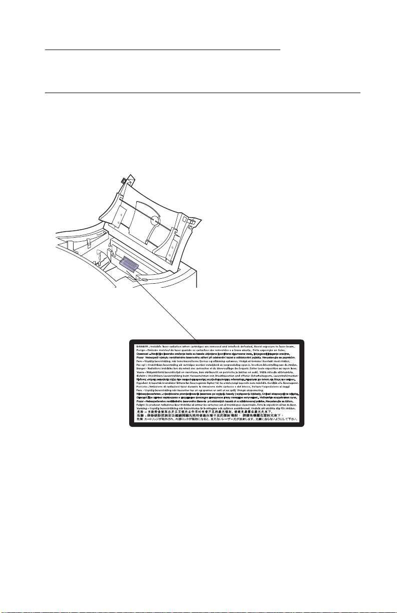
Notices and Safety Information
Laser Notices
The following laser notice labels may be affixed to this printer as
shown:
Notices and Safety Information ix
Page 10

5016-001
Laser Not ice
The printer is certified in the U.S. to conform to the requirements of
DHHS 21 CFR Subchapter J for Class I (1) laser products, and
elsewhere is certified as a Class I laser product conforming to the
requirements of IEC 825.
Class I laser products are not considered to be hazardous. The
printer contains internally a Class IIIb (3b) laser that is nominally a 5
milliwatt gallium arsenide laser operating in the wavelength region of
770-795 nanometers. The laser system and printer are designed so
there is never any human access to laser radiation above a Class I
level during normal operation, user maintenance, or prescribed
service condition.
Laser
Der Drucker erfüllt gemäß amtlicher Bestätigung der USA die
Anforderungen der Bestimmung DHHS (Department of Health and
Human Services) 21 CFR Teil J für Laserprodukte der Klasse I (1).
In anderen Ländern gilt der Drucker als Laserprodukt der Klasse I,
der die Anforderungen der IEC (International Electrotechnical
Commission) 825 gemäß amtlicher Bestätigung erfüllt.
Laserprodukte der Klasse I gelten als unschädlich. Im Inneren des
Druckers befindet sich ein Laser der Klasse IIIb (3b), bei dem es
sich um einen Galliumarsenlaser mit 5 Milliwatt handelt, der Wellen
der Länge 770-795 Nanometer ausstrahlt. Das Lasersystem und der
Drucker sind so konzipiert, daß im Normalbetrieb, bei der Wartung
durch den Benutzer oder bei ordnungsgemäßer Wartung durch den
Kundendienst Laserbestrahlung, die die Klasse I übersteigen würde,
Menschen keinesfalls erreicht.
x Service Manual
Page 11

5016-001
Avis relatif à l’utilisation de laser
Pour les Etats-Unis : cette imprimante est cer t ifiée conforme aux
provisions DHHS 21 CFR alinéa J concernant les produits laser de
Classe I (1). Pour les autres pays : cette imprimante répond aux
normes IEC 825 relatives aux produits laser de Classe I.
Les produits laser de Classe I sont considérés comme des produits
non dangereux. Cette imprimante est équipée d’un laser de Classe
IIIb (3b) (arséniure de gallium d’une puissance nominale de 5
milliwatts) émettant sur des longueurs d’onde comprises entre 770
et 795 nanomètres. L’imprimante et son système laser sont conçus
pour impossible, dans des conditions normales d’utilisation,
d’entretien par l’utilisateur ou de révision, l’exposition à des
rayonnements laser supérieurs à des rayonnements de Classe I .
Avvertenze sui prodotti laser
Questa stampante è certificata negli Stati Uniti per essere conforme
ai requisiti del DHHS 21 CFR Sottocapitolo J per i prodotti laser di
classe 1 ed è certificata negli altri Paesi come prodotto laser di
classe 1 conforme ai requisiti della norma CEI 825.
I prodotti laser di classe non sono considerati pericolosi. La
stampante contiene al suo interno un laser di classe IIIb (3b)
all’arseniuro di gallio della potenza di 5mW che opera sulla
lunghezza d’onda compresa tra 770 e 795 nanometr i. Il sistema
laser e la stampante sono stati progettati in modo tale che le
persone a contatto con la stampante, durante il normale
funzionamento, le operazioni di servizio o quelle di assistenza
tecnica, non ricevano radiazioni laser superiori al livello della classe
1.
Notices and Safety Information xi
Page 12

5016-001
Avisos sobre el láser
Se certifica que, en los EE.UU., esta impresora cumple los
requisitos para los productos láser de Clase I (1) establecidos en el
subcapítulo J de la norma CFR 21 del DHHS (Departamento de
Sanidad y Servicios) y, en los demás países, reúne todas las
condiciones expuestas en la norma IEC 825 para productos láser de
Clase I (1).
Los productos láser de Clase I no se consideran peligrosos. La
impresora contiene en su interior un láser de Clase IIIb (3b) de
arseniuro de galio de funcionamiento nominal a 5 milivatios en una
longitud de onda de 770 a 795 nanómetros. El sistema láser y la
impresora están diseñados de forma que ninguna persona pueda
verse afectada por ningún tipo de radiación láser superior al nivel de
la Clase I durante su uso normal, el mantenimiento realizado por el
usuario o cualquier otra situación de servicio técnico.
Declaração sobre Laser
A impressora está certificada nos E.U.A. em conformidade com os
requisitos da regulamentação DHHS 21 CFR Subcapítulo J para a
Classe I (1) de produtos laser. Em outros locais, está certificada
como um produto laser da Classe I, em conformidade com os
requisitos da norma IEC 825.
Os produtos laser da Classe I não são considerados perigosos.
Internamente, a impressora contém um produto laser da Classe IIIb
(3b), designado laser de arseneto de potássio, de 5 milliwatts
,operando numa faixa de comprimento de onda entre 770 e 795
nanómetros. O sistema e a impressora laser foram concebidos de
forma a nunca existir qualquer possiblidade de acesso humano a
radiação laser superior a um nível de Classe I durante a operação
normal, a manutenção feita pelo utilizador ou condições de
assistência pres critas.
xii Service Manual
Page 13

5016-001
Laserinformatie
De printer voldoet aan de eisen die gesteld worden aan een
laserprodukt van klasse I. Voor de Verenigde Staten zijn deze eisen
vastgelegd in DHHS 21 CFR Subchapter J, voor andere landen in
IEC 825.
Laserprodukt en van klasse I worden niet als ongevaarlijk
aangemerkt. De printer is voorzien van een laser van klasse IIIb
(3b), dat wil zeggen een gallium arsenide-laser van 5 milliwatt m e t
een golflengte van 770-795 nanometer. Het lasergedeelte en de
printer zijn zo ontworpen dat bij normaal gebrui k, bij onderhoud of
reparatie conform de voorschriften , nooit blootste lling mogelijk is
aan laserstraling boven een niveau zoals voorgeschreven is voor
klasse 1.
Lasermeddelelse
Printeren er godkendt som et Klasse I-laserprodukt, i
overenstemmelse med kravene i IEC 825.
Klasse I-laserprodukter betragtes ikke som farlige. Printeren
indeholder internt en Klasse IIIB (3b)-laser, der nominelt er en 5
milliwatt galliumarsenid laser , som arbejder på bølgelængdeområdet
770-795 nanometer. Lasersystemet og printeren er udformet
således, at mennesker aldrig udsættes for en laserstråling over
Klasse I-niveau ved normal drift, brugervedligeholdelse eller
obligatoriske servicebetingelse r.
Notices and Safety Information xiii
Page 14

5016-001
Huomautu s las er laitteesta
Tämä kirjoitin on Yhdysvalloissa luokan I (1) laserlaitteiden DHHS
21 CFR Subchapter J -määrityksen mukainen ja muualla luokan I
laserlaitteiden IEC 825 -määrityksen mukainen.
Luokan I laserlaitteiden ei katsota olevan vaarallisia käyttäjälle.
Kirjoittimessa on sisäinen luokan IIIb (3b) 5 milliwatin
galliumarsenidilaser, joka toimii aaltoalueella 770 - 795 nanometriä.
Laserjärjestelmä ja kirjoitin on suunniteltu siten, että käyttäjä ei
altistu luokan I määrityksiä voimakkaammalle säteilylle kirjoittimen
normaalin toiminnan, käyttäjän tekemien huoltotoimien tai muiden
huoltotoimien yhteydessä.
xiv Service Manual
Page 15

5016-001
Laser-notis
Denna skrivare är i USA certifierad att motsvara kraven i DHHS 21
CFR, underparagraf J för laserprodukter av Klass I (1). I andra
länder uppfyller skrivaren kraven för laserprodukter av Klass I enligt
kraven i IEC 825.
Laserprodukter i Klass I anses ej hälsovådliga. Skrivaren har en
inbyggd laser av Klass IIIb (3b) som består av en laserenhet av
gallium-arsenid på 5 milliwatt som arbetar i våglängdsområdet 770795 nanometer. Lasersystemet och skrivaren är utformade så att det
aldrig finns risk för att någon person utsätts för laserstrålning över
Klass I-nivå vid normal användning, underhåll som utförs av
användaren eller annan föreskriven serviceåtgärd.
Laser-melding
Skriveren er godkjent i USA etter kravene i DHHS 21 CFR,
underkapittel J, for klasse I (1) laserprodukter, og er i andre land
godkjent som et Klasse I-laserproduk t i samsvar med kravene i IEC
825.
Klasse I-laserprodukter er ikke å betrakte som farlige. Skriveren
inneholder internt en klasse IIIb (3b)-laser, som består av en
gallium-arsenlaserenhet som avgir stråling i bølgelengdeområdet
770-795 nanometer. Lasersystemet og skriveren er utformet slik at
personer aldri utsettes for laserstråling ut over klasse I-nivå under
vanlig bruk, vedlikehold som utføres av brukeren, eller foreskrevne
serviceopera sjoner.
Notices and Safety Information xv
Page 16

5016-001
Avís sobre el Làser
Segons ha estat certificat als Estats Units, aquesta impressora
compleix els requisits de DHHS 21 CFR, apartat J, pels productes
làser de classe I (1), i segons ha estat certificat en altres llocs, és un
producte làser de classe I que compleix els requisits d’IEC 825.
Els productes làser de classe I no es consideren perillosos. Aquesta
impressora conté un làser de classe IIIb (3b) d’arseniür de gal.li,
nominalment de 5 mil.liwats, i funciona a la regió de longitud d’ona
de 770-795 nanòmetres. El sistema làser i la impressora han sigut
concebuts de manera que mai hi hagi e xposició a la radiació làser
per sobre d’un nivell de classe I durant una operació normal, durant
les tasques de manteniment d’usuari ni durant els serveis que
satisfacin les condicions prescrites.
xvi Service Manual
Page 17
5016-001
Japanese Laser Notice
Chinese Laser Notice
Notices and Safety Information xvii
Page 18

5016-001
Korean Laser Notice
xviii Service Manual
Page 19

5016-001
Safety Information
• This product is designed, tested and approved to meet strict
global safety standards with the use of specific Lexmark
components. The safety features of some parts may not always
be obvious. Lexmark is not responsible for the use of other
replacement par ts.
• The maintenance information for this product has been
prepared for use by a professional service person and is not
intended to be used by others.
• There may be an increased risk of electric shock and personal
injury during disassembly and servicing of this product.
Professional service personnel should understand this and take
necessary precaut ions.
Consig n es de Séc urité
• Ce produit a été conçu, testé et approuvé pour respecter les
normes strictes de sécur ité globale lors de l'utilisation de
composants Lexmark spécifiques. Les caractéristiques de
sécurité de certain s élémen ts ne sont pas toujours évidente s.
Lexmark ne peut être tenu responsable de l'utilisation d'autres
pièces de rechange.
• Les consignes d'entretien et de réparation de ce produit
s'adressent uniquement à un personnel de maintenance
qualifié.
• Le démontage et l'entretien de ce produit pouvant présenter
certains r isques électr iqu es, le personnel d'entretien qualifié
devra prendre toutes les précautions nécessaires.
Notices and Safety Information xix
Page 20

5016-001
Norme di sicurezza
• Il prodotto è stato progettato, te stato e approvato i n conf ormità a
severi standard di sicurezza e per l’utilizzo con componenti
Lexmark specifici. Le caratteristiche di sicurezza di alcune parti
non sempre sono di immediata comprensione. Lexmark non è
responsabile per l’utilizzo di parti di ricambio di altri produttori.
• Le informazioni riguardanti la manutenzione di questo prodotto
sono indirizzate soltanto al personale di assistenza autorizzato.
• Durante lo smontaggio e la manutenzione di questo prodotto, il
rischio di subire scosse elettriche e danni alla persona è più
elevato. Il personale di assistenza autorizzato, deve, quindi,
adottare le precauzioni necessarie.
Sicherheitshinweise
• Dieses Produkt und die zugehörigen Komponenten wurden
entworfen und getestet, um beim Einsatz die weltweit gültigen
Sicherheitsanforderungen zu erfüllen. Die sicherheitsrelevanten
Funktionen der Bauteile und Optionen sind nicht immer
offensichtlich. Sofern Teile eingesetzt werden, die nicht von
Lexmark sind, wird von Lexmark keinerlei V erantwortung oder
Haftung für dieses Produkt übernommen.
• Die Wartungsinformationen für dieses Produkt sind
ausschließlich für die Verwendung durch einen
Wartungsfachmann bestimmt.
xx Service Manual
Page 21

5016-001
Während des Auseinanderneh men s und der Wartung des Geräts
besteht ein zusätzliches Risiko eines elektrischen Schlags und körperlicher Verletzung. Das zuständige Fachpersonal sollte entsprechende
Vorsichtsmaßnahmen treffen.
Pautas de Seguri dad
• Este producto se ha diseñado, verificado y aprobado para
cumplir los más estrictos estándares de seguridad globa l
usando los componentes específicos de Lexmark. Pu ede que
las características de seguridad de algunas piezas no sean
siempre evidentes. Lexmark no se hace responsable del uso de
otras piezas de recambio.
• La información sobre el mantenimiento de este producto está
dirigida exclusivamente al personal cualificado de
mantenimiento.
• Existe mayor riesgo de descarga eléctrica y de daños
personales durante el desmontaje y la reparación de la
máquina. El personal cualificado debe ser consciente de este
peligro y tomar las precauciones necesarias.
Inform ações de Segurança
• Este produto foi concebido, testado e aprovado para satisfazer
os padrões globais de segurança na utilização de componentes
específicos da Lexmark. As funções de segurança de alguns
dos componentes podem não ser sempre óbvias. A Lexmark
não é responsável pela utilização de outros componentes de
substituição.
• As informações de segurança relativas a este produto
destinam-se a profissionais destes serviços e não devem ser
utilizadas por outras pessoas.
• Risco de choques eléctricos e ferimentos graves durante a
desmontagem e manutenção deste produto. Os profissionais
destes serviços devem estar avisados deste facto e tomar os
cuidados necessários.
Notices and Safety Information xxi
Page 22

5016-001
Informació de Seguretat
• Aquest producte està dissenyat, comprovat i aprovat per tal
d'acomplir les estrictes nor me s de seguretat globals amb la
utililitzac ió de components específics de Lexmark. Les
característiques de seguretat d'algunes peces pot ser que no
sempre siguin òbvies. Lexmark no es responsabilitza de l'us
d'altres peces de recanvi.
• La informació pel manteniment d’aquest producte està
orientada exclusivament a professionals i no està destinada a
ningú que no ho sigui.
• El risc de xoc elèctric i de danys personals pot augmentar
durant el procés de desmuntatge i de servei d’aquest producte.
El personal professional ha d’estar-ne assabentat i prendre les
mesures convenients.
xxii Service Manual
Page 23

5016-001
Notices and Safety Information xxiii
Page 24

5016-001
xxiv Service Manual
Page 25

5016-001
1. Gen e r a l In for mation
The LexmarkTM Optr aTM C710 is a letter quality page printer
designed to attach to an IBM-compatible personal computer and
most computer networks.
General Information 1-1
Page 26

5016-001
Models
The 5016-001 printer is available in the following models:
Model Memory INA Options
C710 32 MB N/A N/A
C710n 32 MB 10 Base 100T N/A
C710dn 64 MB 10 Base 100T • Additional 2x250
paper drawer
•Duplex
Standard Features
Feature Description
Printing Process Dry electrophotographic process using a la ser diode.
Performance • Monochrome, Letter or A4 - up to 16 ppm.
• Color, Letter or A4 - up to 3ppm.
• Color trans parencies, Lett er or A4 - up to 1.8 ppm.
• Monochrome duplexed pages, up to 10 impressions 5 duplexed ppm.
• Color duplexed pages, up to 3 impressions - 1.5
duplexed ppm.
Special Features • Automatic Duplex.
• Color Quality Enhancement Technology (CQET).
• Automatic color screening selection to optimize print
quality based on print type.
• 4 bit color capabilities.
• Color screens whi ch optimize print quali ty.
Print
Addressability
Maximum Print
Speed
(Mono/Color)
Maximum Duplex
Print Speed
(Mono/Color)
600 x 600 dpi, 1200 x 1200 dpi
16/3 ppm (Letter and A4)
5/1.5 ppm (Letter and A4)
1-2 Service Manual
Page 27

5016-001
Feature Description
Paper Input • Standard 250 sheet integrated input tray
Paper Output Top output bin: 250 sheets
Media Size
Supported
Physical
Characteristics
Power Supply AC 120v, 22v - 240v 60Hz (50Hz)
Power
Consumption
Controller Lexmark Controller
Printer
Management
Software
• Multipurpose feeder: 50 sheets
A4, B5, Letter, Legal and Executive
• Width: 18.5” (470mm), Depth 25.5” (645mm), Height
16.0” (405mm).
• Height of 2nd dr awer: 2 x 250 trays 8.9” (223mm).
• Height of duplex option: 5.7” (145mm).
• Weig ht: 79 lbs. (35.8kg) for base model only.
• Weig ht (duplex opti on) 46.22 lbs. (21kg).
• Weig ht (dual tray option) 20.7 lbs. (9.4 kg).
1.2 Kw maximum
MarkVision
computer. Supported in the following environments:
• Windows 95/98
• Windows NT 4.0
•OS/2 Warp
•Macintosh
• UNIX
TM
that lets you manag e your print er from y our
Operator Panel Fr ont cover mounted operator panel for menus.
Exposure
System
Charging System Corona
Deve lopment Non-magne ti c mo no-component
• Laser diode
• Scannin g: Polygon scanner
General Information 1-3
Page 28

5016-001
Feature Description
Fusing System Hot roll fuser 170 degree C
Operating
T emperature
Erase System Light discharge (LED lamp)
Image Transfer
System
PC Drum Photoconductor: OPC (organic photoconductor)
Cleaning System Blade
Printer Memory • 32MB SDRAM
Interfa ce • Base printer: parallel standard Centronics protocol
Internal
Solutions Ports
Printer Options • Optional paper drawer: drawer unit with two 250 sheet
(Hot roll 30mm, backup roll 34mm)
• 10 - 35 degrees C (50 - 95 degrees F)
• Intermediate transfer (primary)
• Transfer roller (secondary)
Note: Some models may ship with m ore memory.
When a duplex unit is i nstalled, 64MB is the
recommended mini m um pri nter memory.
• Maximum usable memory: 384MB
compliant with bi dir ectional IEEE 1284B.
• Network printer: Ethernet standard connection.
• Three ports for network adapters, tri-port adapters,
parallel port adapters or hard disk.
• Three memory slots.
trays installed underneath th e print er.
• Duple x unit: provides tw o sided color or monochrome
printing.
• Hard disk: 2.5 inch hard disk to store f onts, forms, job
statistics and spooled jobs (4gt limi t).
Inter n a l P r in t
Servers
Tri-port Adapter Provides support for the following interfaces:
Internal print servers available to support the follo wing
topologies:
• Ethernet 10BaseT and 10Base2.
• Ethernet 10/100Base TX.
• Token-Ring (connects the printer to a Token-Ring
network via DB9 or FJ45).
• Serial RS-232C/RS-422A (which can als o be
configured to support a class 1 Fax modem.
• High speed infr ared local connecti ons.
• LocalTalk network connection.
1-4 S ervice Manual
Page 29

5016-001
Feature Description
Parallel/USB
Port Adapter
Infrared Adapter For use with the Tri-port adapter. Receiv es infrared beam
Serial Interface
Adapter
Ser ial Cable 5 0- fo o t se rial cable
OptraImage
IEEE 1284 adapter pro vi des additional parall el and USP
port.
from an IrDA-compatible workstation.
• High speed bidi rectional 10-foot and 20-foot 1284B
parallel cables
• 9.8-f oot 1284 A-C parallel cable
TM
Transforms the printer into an easy-to-use networkab le
print/cop y station.
General Information 1-5
Page 30

5016-001
Maintenance Approach
The diagnostic information in this manual leads you to the correct
field replaceable unit (FRU) or part. Use the service error codes,
user status messages, user error messages, service checks, and
diagnostic aids to determine the printer problem and repair the
failure. After you complete the repair, perform tests as needed to
verify the repair.
Tools Required For Service
• Flat-blade screwdriver
• #1 Phillips screwdriver
• #2 Phillips screwdriver
• 7.0 mm nut driver
• 5.5 mm wrench
• Needlenose pliers
• Diagonal pliers
• Spring hook
• Feeler gauges
• Analog or digital multimeter
• Parallel wrap plug 1319128
• Serial wrap plug 1329048
• Twinax/serial debug cable 1381963
• Coax/serial debug cable 1381964
1-6 S ervice Manual
Page 31

5016-001
Options
The following options are available. Some options are not available
in every country. Contact your point of purchase for options availab le
in your country.
• Memory options: 4MB, 8MB, 16MB, 32MB, 64MB and 128MB
• Flash memory options: 2MB, 4MB, 8MB, 16MB
• Integrated network options:
• Token-Ring
• Ethernet 10/100 Base-TX
• Ethernet/PAX card
• Internal IDE disk card
• Ethernet ID Base 2/T
• Tri-Port:
RS-232C or RS-422 serial
Infrared
LocalTalk
• IPDS
• SCS
• USB/Parallel port
• Ethernet/Fax card
• Ethernet 10/100 Base-TX
• Fax modem
• 250/250 dual optional paper tray
• Automatic duplex option
• Hard disk
• Hard disk adapter card
• Optra Forms
TM
hard disk
General Information 1-7
Page 32

5016-001
Operational Theory
Interlock Mechanism
When the front cover assembly, fuser cover or cartridge cover is
open, a CLOSE DOOR message displays indicating the interlock
system is open.
If the front door assembly or the fuser cover are closed, the door
switch actuator 3 [A] moves in the direction of arrow [B].
When the cartridge door is closed the door switch actuator 1 [C]
rotates in the direction shown by arrow [D] and activates the door
switch [E] and laser switch [F].
If either of these doors are not closed, actuator 1 [C] will no t r o tate
and the switches will not turn on.
When door switch [E] is not activated, it prevents the LVPS from
supplying power to the printer.
When the laser switch [F] is not activated, the engine board will not
turn the printhead on.
1-8 S ervice Manual
Page 33

5016-001
Sheet Bypass Paper Feed Unit
Operation of the sheet bypass paper feed unit (multipurpose tray)
When the sheet bypass tray is closed and printing is started,
revolution of the developer/paper feed motor is transmitted to the
clutch gear and timing clutch gear of the sheet bypass paper feed
assembly.
When the bypass paper feed clutch activates, the sheet bypass
paper transfer roll is lowered and touches the paper in the tray.
When the paper transfer roll touches the paper in the paper tray, the
paper is fed into the printer by the actions of the paper transfer roll
and paper feed roll.
As paper is fed to the timing roller by the sheet bypass paper feed
roll, the paper pass sensor detects paper is present. This sensor is
located just prior to the timing roller. After the paper is detected, and
passes through the sensor, the sheet bypass clutch turns off, and
the sheet bypass paper feed and sheet bypass paper transfer roller
stop rotating. At the same time, the paper transfer roller is lifted up
by the return spring so that the paper will touch the timi ng roll and
wait.
Note: If the transparency paper sensor located in front of the timing
roller detects a transparency, the printer slows to the half speed
mode.
At the same time the image is transferred from the organic photo
conductor (OPC) to the transfer belt, the timing clutch turns on and
the timing roll begins rotating. Paper is then fed into the image
transfer area, registering the image on the sheet of paper.
Double feed prevention
The double feed prevention pad contacts the sheet bypass
paper feed roller at a specific pressure. Whenever multiple sheets of
paper are fed, the bottom sheet is stopped by friction of the double
feed prevention pad, which aids in preventing double feeding. Only
the top sheet of paper is fed by the paper feed roller.
The paper pass sensor checks paper fed from the sheet bypass
paper feed assembly. If the sensor does not detect paper during a
specific time, a paper jam error displays.
General Information 1-9
Page 34

5016-001
Detecting paper present
A sheet of paper in the sheet bypass tray is detected by the sheet
bypass paper detect sensor. When the sheet of paper is detected,
the paper detect sensor turns off. When the sheet of paper is not
detected, the sensor turns on.
1-10 Service Manual
Page 35

5016-001
Paper Feed Unit
Operation of the paper feed unit (tray 1)
When the paper cassette (tray 1) is present in the printer, a flag
molded in the right side of the tray contacts the release lever rotating
the paper transfer roll, allowing it to contact the paper in the tray.
When a print command is sent to the printer, the paper feed clutch,
attached to the paper feed roller turns on, which turns the main
motor transmitting to the clutch gear magnet and the paper feed
gears, causing the paper feed roller and paper transfer roller to turn.
Double feed prevention
The double feed prevention pad contacts the sheet bypass paper
feed roller at a specific pressure.
Whenever multiple sheets of paper are fed, the bottom sheet is
stopped by friction of the double feed prevention pad which aids in
the prevention of double feeding. Only the top sheet of paper is fed
by the paper feed roller.
As paper is fed to the timing roller by the paper feed roll, the paper is
detected by the paper pass sensor located just ahead of the timing
roller. After the paper is detected, the paper feed clutch turns off and
the paper feed roller and paper feed transfer roller stop rotating. At
this point the paper touches the timing roller and remains. The paper
pass sensor checks the paper feed from the cassette; if paper is not
detected the printer stops and a paper jam error displays.
De tecting the pap e r
Paper in the casette is detected by the paper detect sensor. When
the paper is detected the sensor turns off. If paper is not detected
the sensor remains off.
Detecting paper level
The amount of paper remaining in tray 1 is detected by the paper
detect sensor. When there is enough paper in tray 1 the sensor
remains off. When the level is low, less than 50 sheets, the sensor
turns on and Load Paper tray 1 displays.
General Information 1-11
Page 36

5016-001
Detecting paper size
Paper size is determined by the paper size detect plate connecting
the inner part of the partition plate which detects the paper size
turning on the corresponding switch. It detects Legal, Letter, A4 or
B5/EXE.
1-12 Service Manual
Page 37

5016-001
Second Paper Feed Unit (Optional Paper Trays)
Constru ct i on of the S ec on d paper feed option
The second paper feed unit consists of two separate feed units
which are the same as the paper feed unit for tra y 1, along with idler
rollers above the paper feed units and paper guides on the side of
the paper feed opening. The interconnect board assembly, drive
module and LVPS for the option is located on the right side frame.
General Information 1-13
Page 38

5016-001
Operation of the Second paper feed unit
When the paper cassette (tray 1) is placed in the printer, a flag
molded to the right side of the tray, contacts the release lever which
rotates the paper transfer roll allowing it to contact the paper in the
tray.
When the command is given to start printing, the optional paper tray
stepper motor rotates, rotating the respective reduction gears. The
rotating reduction gears cause the gears attached to the paper feed
roller and paper transfer roller to start rotating. The paper feed roller
contacts the paper causing the paper to feed to the idler roller. The
one way clutch causes the idler roller to rotate feeding the paper
past the paper pass sensors located prior to the idler roller and the
timing roller. After a predetermined period of time, the paper feed
clutch is turns off and the paper feed roller and paper transfer roller
stop rotating. At this point, the paper stops at the timing roller and
pauses. If the pass thru sensors do not detect paper from the
cassette , a paper j am disp lays.
1-14 Service Manual
Page 39

5016-001
De tecting the pap e r
Paper in the casette is detected by the paper detect sensor. When
the paper is detected the sensor is turns off. If paper is not detected
the sensor remains off.
Detecting paper level
The amount of paper remaining in tray 1 is detected by the paper
detect sensor. When there is enough paper in tray 1 the sensor
remains off. When the level is too low, less than 50 sheets, the
sensor turns on and Load Paper tray 1 message displays.
General Information 1-15
Page 40

5016-001
Detecting paper size
Paper size is determined by the paper size detect plate connecting
the inner part of the partition plate. This plate detects the paper size
turning on the corresponding switch. It detects Legal, Letter, A4 or
B5/EXE.
1-16 Service Manual
Page 41

5016-001
Drive Block
Operation of the Drive Block
Note: The Drive Block consists of the paper feed drive bloc k,
developer drive block, fuser drive block, carriage drive block and
OPC/IMT (Intermediate) drive block.
Refer to the drawing for layout of gears and rollers.
In the paper feed system, transmission is switched by three
electromagneti c clutch e s. In the fuser system a one way cl utch is
provided in the center of the paper path to make paper jams easier
to remove from the fuser unit.
The rotation of the contact cam turns on and off by a spring clutch
and solenoid.
General Information 1-17
Page 42

5016-001
Contact Cam
Operation of transferring from the OPC to the transfer belt
The contact cam is stopped at the position shown in figure below.
The pins fit into the grooves of the cam. Lever 1 and lever 2 are
controlled at the position shown. The pin fits into the groove in lever
1 which controls the position of the transfer roller cam, detaching
transfer roller from the transfer belt. The discharge roller is also
detached from the transfer belt at this time. A pin in the side of lever
2 controls the cleaner lever which controls the position of the
cleaner. The cleaner is detached from the transfer belt.
Operation of transferring from the belt to the paper
The contact cam rotates according to the movement of the solenoid
and spring clutch and stops. The revolution of the cam is transmitted
in the following order: transfer roller, discharge roller and cleaner.
1-18 Service Manual
Page 43

5016-001
Coupling Unit
Operatio n o f the cou pling un it when initializing o r printing
The coupling cam is rotated by the coupling motor. The carriage
position pin slides toward the carriage.
The OPC and carriage are positioned by the movement of the
carriage position pin in the following order:
After initializing or printing, the coupling shaft, detent shaft and
carriage position pin slide in reverse, by rotating the coupling motor
in reverse in order to reset the position of the OPC and carriage.
Manual resetting
By rotating the knob counterclockwise 180 degrees, the same
operation as mentioned above can be performed manually.
General Information 1-19
Page 44

5016-001
1-20 Service Manual
Page 45

5016-001
Carriage Unit
Rotation and stopping operation of the carriage
The carriage rotates by 90 degree angles when switching from one
color to another. The carriage drive motor (pulse motor) turns on to
rotate the carriage. After the carriage home position sensor detects
the carriage home position detect rib, the operation is performed as
many times as the specified number of pulses; then the carriage is
stopped at the specified position.
Detecting the carriage
When initializing, the carriage turns one turn so that the carriage
home position sensor can detect the cartridge detect rib located on
the toner cartridge.
Detecting the carriage home position
Four carriage home position detect ribs are located on the carriage
right side plate, one of which is longer that the other three. The
position of respective color toner cartridges is detected by the length
of the ribs while initializing.
General Information 1-21
Page 46

5016-001
Toner Cartridge Uni t
Detecting a new cartridge
When initializing, a reflector attached to the new cartridge detect
lever installed in the cartridge, reflects light. A new cartridge detect
sensor installed in the bottom part of the printer, allows the ca rtridge
to be detected. Once the cartridge has been used the new cartridge
detect lever makes a turn and no additional reflections occur.
A new cartridge detect sensor:
• Will be high “H” when a cartridge has been used. (Sensor
output at connector)
• Will be low “L” when a cartridge is present.
1-22 Service Manual
Page 47

5016-001
De tecting ton er level
The toner level sensor is installed in the bottom of the printer and
emits light from infrared LED’s mounted in the sensor assembly, to
mirrors mounted at an angle of the cartridge sensor window.
• No toner in cartridge: Will be high “H”
• Toner left in cartridge: Will be low “L” (toner sensor output at
connector)
General Information 1-23
Page 48

5016-001
Intermediate Transfer Unit
Function of the intermediate transfer unit
The intermediate transfer unit consists of the transfer belt, belt
cleanser and waster toner bottle in which cleaned toner is collected.
The transfer belt is made of an electrically conductive resin. The
toner image, when placed on the organic photoconductor (OPC)
drum is transferred onto the transfer belt by an electric field. The belt
makes four turns, so that four color toner images, yellow (Y),
magenta (M), cyan (C) and black (BK) are transferred onto the belt.
The color image is formed on the transfer belt and the entire image
is transferred onto paper by the transfer roller forming the color
image on the paper.
Note: While the four color toner images are still on the transfer belt
the transfer roller, discharge roller and cleaning roller are pulled
away from the transfer belt. An optical reflector is attached on one
edge of the outer circumference of the transfer belt and is used by
the home position sensor to detect the position of the belt. After the
image is transferred to the paper, any toner remaining on the belt is
cleaned by the cleaning roller and transferred through the transport
coil into the waste toner bottle in the belt unit. When cleaning the
remaining toner, after the image has been transferred to paper, the
transfer roller, discharge roller and cleaning roller, touch the transfer
belt.
1-24 Service Manual
Page 49

5016-001
The waste toner bottle is partitioned and collected toner is
transferred into respective partitions in order. When the bottle is
filled to capacity, it is detected by the waste toner bottle full sensor.
The cleaner consists of the discharge roller, cleaning roller, blade
and toner transport coil. The toner remaining on the belt is
discharged by the discharge roller, transferred to the cleaning roller,
scraped from the cleaning roller by the cleaning blade and
transported to the waste toner bottle by the transport coil.
General Information 1-25
Page 50

5016-001
Operation of the drive for the intermediate transfer unit
The belt gear is rotated by the belt drive gear, rotating the transfer
belt. At the same time the cleaning roller and discharge roller are
rotated by the timing belt and gear. The cleaner lever is shifted by a
pin and the cleaning roller is detached from the transfer belt. At the
same time, the contact pin is shifted by a lever causing the contact
cam to turn. The transfer roller and discharge roller are detached
from the transfer belt by the contact cam.
1-26 Service Manual
Page 51

5016-001
Fuser/Paper Exit Unit
Operation of the fuser and paper exit
When the power switch is turned on the fuser lamp is turned on by
the low voltage power supply while the hot roll begins to heat.
When the hot roll reaches approximately 170 degrees C the fuser
drive motor is turns on and the backup roll, hot roll and paper exit
rollers start turning. After a specified time the fuser drive motor turns
off and the printer is ready to print.
The thermistor continuously detects the temperature of the surface
of the hot roll, turning the fuser lamp on and off keeping the surface
of the hot roll at a specified temperature.
After the last sheet of paper prints and the paper exit sensor detects
the exit of the sheet of paper, the fuser drive motor turns off and the
backup roll, hot roll and paper exit roll stop turning.
A thermostat is provided to protect the fuser unit should an unusual
rise in temperature occur in the hot roll assembly. If activated, the
thermostat shuts off power to the fuser lamp.
A cleaner unit is located on top of the hot roll. The oil roller in the
cleaner unit supplies a specified amount of oil to the hot roll
preventing an offset. The cleaning roller prevents the hot roll from
becoming dirty from a buildup of toner or paper dust.
If power is applied to the fuser unit and a cleaner unit has not been
installed, the paper exit sensor lever is detached from the paper exit
sensor and the printer proceeds to the paper jam state, preventing
the hot roll, backup roll and paper exit roller from rotating.
General Information 1-27
Page 52

5016-001
Detecting New Cleaning Unit
Detecting the cleaning unit in the Fuser Assembly
A thermal fuse is attached on the contact point A in the cleaner unit.
When the cleaner unit is placed inside the fuser unit, contact A
contacts contact B. The circuit is then complete through the thermal
fuse. When primary power is applied to the printer, a current flows
through the thermal fuse detecting a new cleaner unit and the print
counter resets to ‘Zero.’
As the temperature of the hot roll and cleaning roll rise, the
temperature around the thermal fuse also rises, eventually causing
the thermal fuse to blow.
Note: The fuse will generally blow after primary power has been
applied following the printing of two or three sheets of paper. At this
time the temperatures of the blown fuse and surrounding parts are
70 degrees C and about 100 degrees respectively.
When predetermined shee ts of paper are printed, a warning
displays. When additional sheets are printed, the printer stops until
the unit is replaced. When a new unit is placed, repeat the previous
step.
1-28 Service Manual
Page 53

5016-001
Duplex Unit (Option)
One side print
The print fed by the paper feed rollers in tray 1 in the printer and in
the second paper feed unit is halted temporarily at the timing roller
for registration. The paper then passes through the transfer unit, in
which the image is formed, and is fused in the fuser assembly. When
the paper exit sensor detects paper, the drive of the automatic two
sided print unit starts, switching the gate claw to the outer side to
eject the page. The paper that is transported by the paper exit roller
in the printer is ejected into the paper exit tray by the paper exit roller
in the duplex unit.
General Information 1-29
Page 54

5016-001
Tw o sided print
When the printer has been set for two sided print mode and start is
pressed the following occurs:
When the setting is two pages. The paper feed roller in the printer
starts rotating. The paper is transported by the timing roller and the
back page is printed. The paper then passes through the fuser roller.
When the leading edge of the paper reaches the paper exit sensor in
the fuser, t he upper unit motor s tarts rotating in the normal direction,
switching the gate claw to the inner side to receive the paper. When
the paper reaches the upper paper pass sensor, through the paper
transport roller, the rotation of the motor is switched to the
high-speed mode. At the same time, the lower unit motor begins
rotating in the normal direction in the high speed mode, transporting
the paper to the storage area in the lower unit through the rear unit.
1-30 Service Manual
Page 55

5016-001
When the trailing edge of the paper passes through the reverse
sensor f ille r (S4], the m o to r rotates in the rever se dire c ti on
transporting the paper in reverse. The print is transported to the
timing roller in the printer through the rollers in the curved area, the
skew correction mechanism and the paper feed roller. The paper is
then fed through the transfer and fuser units in sync with the image
of the front page as it is transported onto the middle transfer unit.
When the leading edge of the paper reaches the paper exit sensor
[S0] in the printer, the upper unit motor starts rotating in the reverse
direction, switching the gate claw to the paper exit mode. The paper
then exits through the paper exit roller in the upper unit.
General Information 1-31
Page 56

5016-001
When the setting is four pages
The back page of the first printed page is printed after Print Start is
pressed. The print is received in the upper unit through the above
step and then halted when it reaches the paper exit sensor [S5]
through the storage, revers e and skew correction mechanisms in the
lower unit. The second page is then fed from the selected paper tray
and its back page is printed and transported to the upper unit. The
second page stops when it reaches the upper paper pass sensor
[S2] and is held there. The first page waiting in the lower unit is fed t o
the timing roller in the printer. When the timing roller rotates, the
motors in the upper and lower units rotate in high speed mode,
transferring the second page, waiting in the upper unit, to position in
the lower unit. At this time, the front page of the first page is printed
and then exits the printer. The printer then prints the front page of
the second page and finally the second page, as it is finished, exits
the printer.
1-32 Service Manual
Page 57

5016-001
When the setting is not less than six pages or three prints
This operation stages pages in the lower and upper units and
alternates transportation as shown in the preceding steps. These
steps are performed successively.
General Information 1-33
Page 58

5016-001
Exit of the on e sided print
When the printed page passes through the paper exit sensor in the
printer, the upper duplex unit motor rotates in the reverse direction,
rotating the gate claw in reverse, so that paper is ejected to the
paper exit tray. When the page passes through the paper exit sensor
in the printer, the upper duplex unit motor rotates in the normal
direction in low speed mode, rotat ing the gate claw normally in order
to receive the page. When the page passes through the pass
sensor, the motor switches to high speed mode transpor ting the
page to the duplex rear unit.
1-34 Service Manual
Page 59

5016-001
Detecting the paper exit tray open/close
When the paper exit tray opens to remove a jammed print, the
sensor lever shuts off the open/closed sensor so that detection is
performed.
Detect in g th e duplex upper uni t ope n/close
When the upper unit opens, the actuator detaches from the right
sensor pin in the right hinge. The actuator, pulled by the return
spring, closes the sensor and detection is performed.
General Information 1-35
Page 60

5016-001
Gate claw operation, when print exits
When the leading edge of a duplexed page prints, it turns the paper
exit sensor in the printer on. The duplex upper unit motor starts
rotating in the reverse direction, rotating the claw gear. The gate
claw rotates counterclockwise feeding the page to the paper exit
roller. The page then exits the printer.
When the leading edge of a simplexed page prints, it actuates the
paper exit sensor and the duplex upper unit motor rotates in the
normal direction. This rotation is then transmitted to the claw gear
and limiter disk and the gate claw rotates in a clockwise direction so
that the page can print on the opposite side.
1-36 Service Manual
Page 61

5016-001
Storage of the paper in the duplex unit
The page that is transported from the duplex rear unit pushes on the
gate claw and is stored in the duplex lower tray unit. When the
trailing edge of the page passes through gate claw 2, gate claw 2 is
rotated by the gate claw spring until the gate claw lever touches the
stopper, switching to reverse paper exit mode.
General Information 1-37
Page 62

5016-001
Operation of the motor
When the leading edge of the paper reaches the paper pass sensor
in the duplex upper unit, the upper unit motor goes into high speed
mode (270m/sec). At this time, the duplex lower unit motor rot ates in
the normal direction. The rotation is transmitted to the gears in the
lower unit as shown. When the leading edge of the paper reaches
the paper pass sensor [S3], the duplex upper unit motor stops
rotating.
1-38 Service Manual
Page 63

5016-001
When the page is transported from the duplex rear unit for storage,
the reverse sensor detects the paper. After the sensor detects the
paper, for a specified time, the motor turns off and the print is stored.
The duplex lower unit reverse motor supplies drive to the duplex rear
unit and tray through gear 18Z. When the duplex tray is pulled out,
the interlock switch opens and interrupts the circuit to the reverse
motor. The tray condition sensor detects the position of the duplex
tray and whether it is correctly installed. The transport sensor
detects whether the page being transport ed pas ses though to the
printer.
General Information 1-39
Page 64

5016-001
When paper is fed from the 2nd paper option, the chassis side input
gear rotates in [B] direction. The drive is transmitted to the one way
gear 16Z through the store roller drive shaft, rotating the one way
gear 16Z in the [B] direction.
Note: Drive is not transmitted when the rotation is in the [A]
direction, due to the one way clutch [A]. The timing belt drives,
turning the idler rollers in the [B] direction, while transporting the
page in the [B] directio n.
1-40 Service Manual
Page 65

5016-001
Skew Correction
The holder mounted on the lower side of the rear cover is inclined
about 3 degrees, in the paper pass direction. The page is brought to
the opposite side of the skew correction mechanism in the duplex
lower tray unit by this inclination for the preparation of skew
correction. To mount the holder, engage the tab of the holder with
the second groove from the rib of the rear cover.
General Information 1-41
Page 66

5016-001
Acronyms
CSU Customer Setup
DRAM Dynamic Random Access Memory
EDO Enhanced Data Out
EP Electrophotographic Process
EPROM Erasable, Programmable Read-Only Memory
ESD Electrostatic Discharge
FRU Field Replaceable Unit
GB Giga Byte
HVPS High Voltage Power Supply
LASER Light Amplification Stimulated Emission of Radiation
LCD Liquid Crysta l Display
LED Light-Emitting Diode
LVP S Low Voltage Power Supply
MROM Masked Read Only Memor y
NVRAM Nonvolatile Random Access Memor y
OEM Original Equip men t Manufacturer
PC Photoconductor
RIP Raster Imaging Processor
ROM Read Only Memory
SIMM Sin gle In-Line Memory Module
SRAM S t atic Random Ac cess Memo ry
UPR Used Parts Return
V ac Volts alternating current
V dc Volts direct current
1-42 Service Manual
 Loading...