

Page 1

Revised: March 24, 2006
Lexmark™ 910 Series
Photo Jetprinter™
• Table of Contents
•Start Diagnostics
4110-XXX
• Safety and Notices
• Trademarks
•Index
Lexmark and Lexmark with diamond
design are trade ma rks of Lexmark
International, Inc., registered i n the
United States and/or ot her countries.
Page 2

4110-XXX
Editi on: March 24, 2006
The following paragraph does not apply to any country where such provisions are
inconsistent with local law: LEXMAR K INTERNATIONAL, INC. PROVIDES THIS
PUBLICATION “AS IS” WITHOUT WARRANTY OF ANY KIND, EITHER EXPRESS OR
IMPLIED, INCLUDING , BUT NOT LIMITED TO, THE IMPLIED WARRANTIES OF
MERCHANTABILITY OR FITNESS FOR A PARTICULAR PURPOSE. Some states do
not all o w di sc la im er o f e x pres s o r i mpl i ed wa rr an tie s i n c ertai n t ra ns act ion s; t he refore, t hi s
statement may not apply to you.
This publication could include technical inaccuracies or typographical errors. Changes are
periodically made to the info rmation herein; these changes will be incorpo rated in later
editions. Improvements or changes in the products or the programs described may be
made at any time.
Comments may be addressed to Le xmark International, Inc., Department D22A/032-2 ,
740 West New Circle Road, Lexington, Kentucky 40550, U.S.A or e-mail at
ServiceInfoAndTraining@Lexmark.com. Lexmark may use or distribute any of the
information you supply in any way it believes appropriate withou t incurring any obligation
to yo u.
Lexmark and Lexmark with diam ond design are trademarks of Lexmark International,
Inc. , registered in the Unit ed States and/or other countries. Photo Jetprinter is a
trademark of Lexmark Interational, Inc.
Other trademarks are the property of their respective owners.
© 2004 Copyright Lexmark International, Inc.
All rights reserved.
UNITED STATES GOVERNMENT RIGHTS
This software and any accompanying documentation provided under this agreement are
commercial computer software and documentation develope d exclusively at priva te
expense.
U.S.A. P/N 12G9405
Japanese P/N 12G9406
Page 3

4110-XXX
Table of contents
Preface. . . . . . . . . . . . . . . . . . . . . . . . . . . . . . . . . . . . . . . . . . . . . . . . .v
Safety information. . . . . . . . . . . . . . . . . . . . . . . . . . . . . . . . . . . . . . . vi
General information . . . . . . . . . . . . . . . . . . . . . . . . . . . . . . . . . . . . 1-1
Control panel and menu . . . . . . . . . . . . . . . . . . . . . . . . . . . . . . . . . . 1-2
Using the control panel . . . . . . . . . . . . . . . . . . . . . . . . . . . . . . . . 1-2
Control panel buttons. . . . . . . . . . . . . . . . . . . . . . . . . . . . . . . . . . 1-2
Print quality . . . . . . . . . . . . . . . . . . . . . . . . . . . . . . . . . . . . . . . . . 1-4
Power consumption . . . . . . . . . . . . . . . . . . . . . . . . . . . . . . . . . . . 1-4
Maintenance approach . . . . . . . . . . . . . . . . . . . . . . . . . . . . . . . . . . . 1-4
Abbreviations . . . . . . . . . . . . . . . . . . . . . . . . . . . . . . . . . . . . . . . . . . 1-5
Diagnostic information . . . . . . . . . . . . . . . . . . . . . . . . . . . . . . . . . 2-1
Start . . . . . . . . . . . . . . . . . . . . . . . . . . . . . . . . . . . . . . . . . . . . . . . . . 2-1
Power-On Self Test (POST) sequence . . . . . . . . . . . . . . . . . . . . 2-1
POST symptom table . . . . . . . . . . . . . . . . . . . . . . . . . . . . . . . . . 2-1
Sym p tom ta b le s . . . . . . . . . . . . . . . . . . . . . . . . . . . . . . . . . . . . . . 2-2
Service checks . . . . . . . . . . . . . . . . . . . . . . . . . . . . . . . . . . . . . . . . . 2-4
Maintenance station service check . . . . . . . . . . . . . . . . . . . . . . . 2-4
Operator panel button service check . . . . . . . . . . . . . . . . . . . . . . 2-5
LCD assembly display service check . . . . . . . . . . . . . . . . . . . . . . 2-5
Paper feed service check. . . . . . . . . . . . . . . . . . . . . . . . . . . . . . . 2-6
Paper path service check. . . . . . . . . . . . . . . . . . . . . . . . . . . . . . . 2-8
Power service check . . . . . . . . . . . . . . . . . . . . . . . . . . . . . . . . . . 2-8
Print quality service check . . . . . . . . . . . . . . . . . . . . . . . . . . . . . . 2-9
Transport carrier service check . . . . . . . . . . . . . . . . . . . . . . . . . 2-10
Error codes . . . . . . . . . . . . . . . . . . . . . . . . . . . . . . . . . . . . . . . . . . . 2 -12
Catastrophic error . . . . . . . . . . . . . . . . . . . . . . . . . . . . . . . . . . . 2-12
Non-catastrophic error . . . . . . . . . . . . . . . . . . . . . . . . . . . . . . . . 2-14
Diagnostic aids . . . . . . . . . . . . . . . . . . . . . . . . . . . . . . . . . . . . . . . . 3-1
Self test mode . . . . . . . . . . . . . . . . . . . . . . . . . . . . . . . . . . . . . . . . . 3-1
Repair informatio n . . . . . . . . . . . . . . . . . . . . . . . . . . . . . . . . . . . . . 4-1
Handling ESD-sensitive parts . . . . . . . . . . . . . . . . . . . . . . . . . . . . . . 4-1
Removal procedures . . . . . . . . . . . . . . . . . . . . . . . . . . . . . . . . . . . . 4-2
Top cover assembly removal. . . . . . . . . . . . . . . . . . . . . . . . . . . . 4-2
Control panel door assembly removal . . . . . . . . . . . . . . . . . . . . . 4-4
Card reader removal . . . . . . . . . . . . . . . . . . . . . . . . . . . . . . . . . . 4-5
Print engine assembly removal . . . . . . . . . . . . . . . . . . . . . . . . . . 4-6
Base assembly removal. . . . . . . . . . . . . . . . . . . . . . . . . . . . . . . . 4-7
Carrier assembly removal . . . . . . . . . . . . . . . . . . . . . . . . . . . . . . 4-8
System board removal. . . . . . . . . . . . . . . . . . . . . . . . . . . . . . . . 4 -10
Transport carrier motor removal. . . . . . . . . . . . . . . . . . . . . . . . . 4-12
iii
Page 4

4110-XXX
Maintenance station removal . . . . . . . . . . . . . . . . . . . . . . . . . . .4-14
Card reader door removal . . . . . . . . . . . . . . . . . . . . . . . . . . . . . .4-16
ASF guide with spring removal . . . . . . . . . . . . . . . . . . . . . . . . . .4-17
Connector locations . . . . . . . . . . . . . . . . . . . . . . . . . . . . . . . . . . . .5-1
System board . . . . . . . . . . . . . . . . . . . . . . . . . . . . . . . . . . . . . . . .5-1
Preventive maintenance . . . . . . . . . . . . . . . . . . . . . . . . . . . . . . . . .6-1
Lubrication specifications . . . . . . . . . . . . . . . . . . . . . . . . . . . . . . . . .6-1
Parts catalog . . . . . . . . . . . . . . . . . . . . . . . . . . . . . . . . . . . . . . . . . .7-1
How to use the parts catalog . . . . . . . . . . . . . . . . . . . . . . . . . . . . . . .7-1
Assembly 1: Covers . . . . . . . . . . . . . . . . . . . . . . . . . . . . . . . . . . .7-2
Assembly 2: Electronics/carrier transport . . . . . . . . . . . . . . . . . . .7-4
Index . . . . . . . . . . . . . . . . . . . . . . . . . . . . . . . . . . . . . . . . . . . . . . . . X-1
iv Service Manual
Page 5

4110-XXX
Preface
This manual describes the 910 Series Photo Jetprinter (4110-XXX)
and contains maintenance procedures for service personnel. It is
divided into the following chapters:
1. Gene r al infor m ation contains a general description of the
printer and the maintenance approach used to repair it. Special
tools and test equipment are listed in this chapter, as well as
general environmental and safety instructions.
2. Diagnostic information contains an error indicator table,
symptom tables, and service checks used to isolate failing field
replaceable units (FRUs).
3. Diagnostic aids contains tests and checks used to locate or
repeat symptoms of printer problems.
4. Repair informa tio n provides instructions for making printer
adjustments and removing and installing FRUs.
5. Connector locations uses illustrations to identify the connector
locations and test points on the printer.
6. Preventive maintenance contains the lubrication specifications
and recommendations to prevent problems.
7. Parts catalog conta ins illustrations and part numbers for
individual FRUs.
Preface v
Page 6

4110-XXX
Safety information
• This product is designed, tested and approved to meet strict
global safety standards with the use of specific Lexmark
components. The safety features of some parts may not always
be obvious. Lexmark is not responsible for the use of other
replacement parts.
• The maintenance information for this product has been
prepared for use by a professional service person and is not
intended to be used by others.
• There may be an increased risk of electric shock and personal
injury dur ing disassem bly and ser v icing of this product.
Professional service personnel should understand this and take
necessary precautions.
Consignes de Sécurité
• Ce produit a été conçu, testé et approuvé pour respecter les
normes strictes de sécurité globale lors de l'utilisation de
composants Lexmark spécifiqu es. Les caractéristiques de
sécurité de certains éléments ne sont pas toujours évidentes.
Lexmark ne peut être tenu responsable de l'utilisation d'aut res
pièces de rechange.
• Les consignes d'entretien et de réparation de ce produit
s'adressent uniquement à un personnel de m aintenance
qualifié.
• Le démontage et l'entretien de ce produit pouvant présenter
certains risques électriques, le personnel d'entretien qualifié
devra prendre toutes les précautions nécessaires.
vi Service Manual
Page 7

4110-XXX
Norme di sicurezza
• Il pr odotto è stato progettato, testato e approvato in conformità a
severi standard di sicurezza e per l’utiliz zo con componenti
Lexmark specifici. Le caratteristiche di sicurezza di alcune parti
non sempre sono di immediata comprensione. Lexmark non è
responsabile per l’utilizzo di parti di ricambio di altri produttori.
• Le informazioni riguardanti la manutenzione di questo prodotto
sono indirizzate soltanto al personale di assistenza autorizzato.
• Durante lo smontaggio e la manutenzione di questo prodotto, il
rischio di subire scosse elettriche e danni alla persona è più
elevato. Il personale di assistenza autorizzato, deve, quindi,
adottare le precauzioni necessarie.
Sicherheitshinweise
• Dieses Produkt und die zugehörigen Komponenten wurden
entworfen und getestet, um beim Einsatz die weltweit gültigen
Sicherheitsanforderungen zu erfüllen. Die sicherheitsrelevanten
Funktionen der Bauteile und Optionen sind nicht immer
offensichtlich. Sofern Teile eingesetzt werden, die nicht von
Lexmark sind, wird von Lexmark keinerlei Verantwortung oder
Haftung für dieses Produkt übernommen.
• Die Wartungsinformationen für dieses Produkt sind
ausschließlich für die Verwendung durch einen
Wartungsfachmann bestimmt.
• Während des Auseinandernehmens und der Wartung des
Geräts besteht ein zusätzliches Risiko eines elektrischen
Schlags und körperlicher Verletzung. Das zuständige
Fachpersonal sollte entsprechende Vorsichtsmaßnahmen
treffen.
Safety i n fo rmat io n vii
Page 8

4110-XXX
Pautas de Seguridad
• Este producto se ha diseñado, verificado y aprobado para
cumplir los más estrictos estándares de seguridad global
usando los componentes específicos de Lexmark. Puede que
las características de seguridad de algunas piezas no sean
siempre evidentes. Lexmark no se hace responsable del uso de
otras piezas de recambio.
• La in formaci ón sobre el mantenimiento de este producto está
dirigida exclusivamente al personal cualificado de
mantenimiento.
• Existe mayor riesgo de descarga eléctrica y de daños
personales durante el desmontaje y la reparación de la
máquina. El personal cualificado debe ser conscien te de este
peligro y tomar las precauciones necesarias.
Informações de Segurança
• Este produto foi concebido, testado e aprovado para satisfazer
os padrões globais de segurança na utilização de componentes
específicos da Lexmark. As funções de segurança de alguns
dos componentes podem não ser sempre óbvias. A Lexmark
não é responsável pela utilização de outro s component es de
substituição.
• As informações de segurança relativas a este produto
destinam-se a profissionais destes serv iços e não devem s er
utilizadas por outras pessoas.
• Risco de choques eléctricos e ferimentos graves durante a
desmontagem e manutenção deste produto. Os profissionais
destes serviços devem estar avisados deste facto e tomar os
cuidados necessári os.
viii Service Manual
Page 9

4110-XXX
Informació de Seguretat
• Aquest producte està dissenyat, comprovat i aprovat per tal
d'acomplir les estrictes normes de seguretat globals amb la
utililització de components específics de Lexmark. Les
característiques de seguretat d'algunes peces pot ser que no
sempre siguin òbvies. Lexmark no es responsabilitza de l'us
d'altres peces de recanvi.
• La informació pel manteniment d’aquest producte està
orientada exclusivament a professionals i no està destinada a
ningú que no ho sigui.
• El risc de xoc elèctric i de danys personals pot augmentar
durant el procés de desmuntatge i de servei d’aquest producte.
El personal professional ha d’estar-ne assabentat i prendre les
mesures convenients.
Safe ty inform at ion ix
Page 10
4110-XXX
x Service Manual
Page 11
4110-XXX
1. Gen e r a l in for matio n
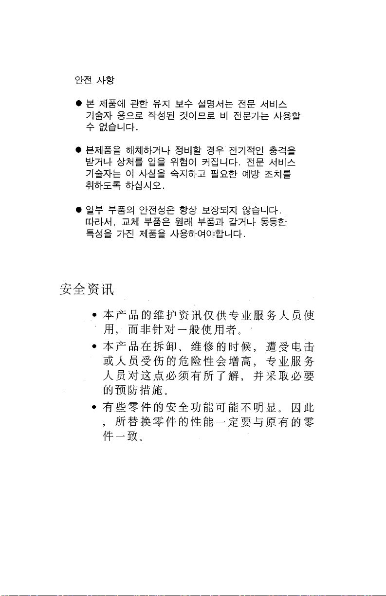
The Lexmark™ 910 Series Photo Jetprinter™ (4110-XXX) is a small
personal inkjet printer specifically for standalone photographic
printing. The photoprinter incorporates a new photo control operator
panel into the cover and slots to support the compact flash and
smar t media.
.
General information 1-1
Page 12
4110-XXX
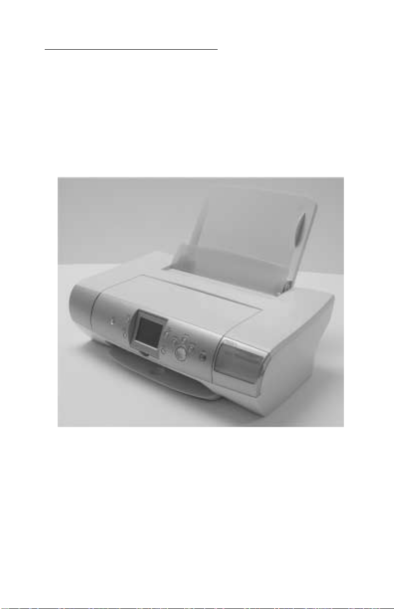
Control panel and men u
Using the control pa nel
The control panel has a blue-LED-backlit power button. The card
reader bezel has a single blue LED to indicate memory card inserted
and memory card activity . As soon as a memory card is inserted and
while the card remains inserted, the LED is lit solid. When the card is
being actively read from or written to, the LED should blink at the
prescribed rate.
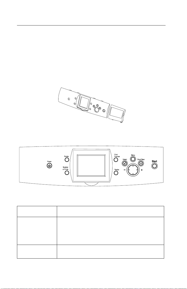
Control panel buttons
Buttons Functions
Power Tur ns on power. At power up, the printer turns on the
card reader LED and the co lor gr aphic s LCD . The car d
reader LED is on during power up, changing to of f
when the card reader is accessible for memory card
insertion.
Start Starts the selected operation. Us e this button to select
1-2 Service Manual
color or mono printing from the Phot o m enu.
Page 13

4110-XXX
Buttons Functions
Up arrow
Down arrow
Left arrow
Right arrow
Resize Sets the image siz e of photos in the Photo Selecti on
Number of Prints Changes the number of copies to print.
Rotate Rotates the image in the LCD di splay by 90° CCW f or
Select Selects photos in Photo mode and cancels the
Print Preview Shows how photos will print on the page.
Stop/Clear Cancels a print job bef ore it begins printing.
Menu Enters/exits the menus.
Navigates menu items on the LCD.
Btowses and choose options on the LCD
mode. In Photo Crop mode, the button changes the
zoom of the ROI. The Region of Intere st is a portion of
a photo or an image that is ide ntified by a green
outline . For photos, it is t he portion of the pho to that
displays based on the curre n t phot o size select ion.
Also used with the Resize button when croppi ng
photos and for indicating the regi on to print.
each time the button is pressed. Also used to rotate
the ROI when in the Crop function of the Photo mode
menu.
displayed photo when pres sed again.
General information 1-3
Page 14

4110-XXX
Print qua li ty
Mono print reso lu t ion:
Quick - 300 x 600 dpi
Normal - 600 x 600 dpi
Photo - 1200 x 1200 dpi
Color print resol ut i on:
Quick - 600 x 600 dpi
Normal - 1200 x 1200 dpi
Photo - 4800 x 1200 dpi
Power consumption
Printing - 13.08 Watts
Idle - 8.5 Watts
Sleep - 6.6 Watts
Maintenance approach
The diagnostic information in this manual leads you to the correct
field replaceable unit (FRU) or part. Use the error indicator charts,
symptom index, service checks, and diagnostic aids to determine
the symptom and repair the failure. Begin with “Start” on page 2-1.
This printer can be serviced without being connected to a host
computer.
After you complete the repair, perf orm tests as needed to verify the
repair.
1-4 Service Manual
Page 15

4110-XXX
Abbreviations
CIS Contact Image Sensor
CSU Customer Setup
EOF End of Forms
ESD E lectr ostatic Discharge
FRU F ield Replac eable Unit
HV High Voltage
LCD Liquid Crystal Display
LED Light-Emitting Diode
LV Low Voltage
NVRAM Nonvolatile Random Access Memory
OEM Original Equipment Manufacturer
POST Power-On Self Test
ROI Region of Interest
V ac Volts alternating current
V dc Volts direct current
General information 1-5
Page 16

4110-XXX
1-6 Service Manual
Page 17

4110-XXX
2. Diagnostic information
Start
Use the post symptom table, symptom tables, and service checks in this
chapter to determine the printer failure.
Power-On Self Test (POST) sequence
Plug the printer in and check for a correct POST operation by
observing the following:
1. The Power button light turns on.
2. The LCD turns on and displays “Lexmark.”
3. The carrier moves off the maintenance station and then returns.
4. The paper feed motor cycles and then turns off.
Note: After the above sequence occurs, the power button light and
LCD remain on.
If your printer complete s POST with no errors, g o to the “Sympto m tabl es”
on page 2-2
If your printer does not complete POST, locate the sympt om in the following
table and tak e the appropriate actio n.
, locate the symptom and take the appropriate action.
POST symptom table
Symptom Action
No motors run Go to the “Power service chec k” on
page 2-8.
Paper feed gears do not turn Go to the “Paper feed service
check” on page 2-6.
• Carrier does not move
• Carrier slams side frame
• Blank display
• All diamonds displayed af ter POST
• Display diff ic u lt to re ad
• Display OK, buttons do not function
• One or mor e buttons do not f unction
Go to the “Transport carrier service
check” on page 2-10.
Go to the
service check” on page 2-5
“LCD assembly disp lay
.
Diagnostic information 2-1
Page 18

4110-XXX
Symptom tables
Locate the symptom in the following tables and take the appropriate
action.
Transport carrier problems
Symptom Action
• No carrier movement
• Slow carrier movement
• Carrier stops
• Carrier slam s si de frame
Go to the “Transport carrier service
check” on page 2-10.
Communications problems
Symptom Action
Printer not communicating with
host computer.
Check the USB connec tion (connec tor
J2). If the connection is good and
problem persists, repl ace the system
board. Go to “System board removal”
on page 4-10.
Maintenance station problems
Symptom Action
• F ails to cap the printhead
• F ails to clean the printhead
Go to the “Maintenance station
service check” on page 2-4.
2-2 Service Manual
Page 19

4110-XXX
Paper feed problems
Symptom Action
• Fails to pick pape r
• Picks more than one sheet of
paper
• Picks paper but fails to feed
• Paper jams
• Paper fails to exit
• Noisy paper feed
Paper skews Go to the “Paper path service check”
Go to the “Paper feed service chec k”
on page 2-6.
on page 2-8.
Power prob le ms
Symptom Action
No po we r in printe r Go to t h e “Power service check” on
page 2-8.
Print quality problems
Symptom Action
• Voids in characters
• Light print
• Prints off the page
• Fuzzy print
• Carrier moves but does not print
• Printhead drying prematur ely
• Excessive ink flow (Floodi ng)
• Horizontal banding
Go to the “Prin t qu a lit y service c heck ”
on page 2-9.
• Ink smearing
• Vertical streaks on paper
• Print lin e s crow ded
Go to the “Paper feed service chec k”
on page 2-6.
Diagnostic information 2-3
Page 20

4110-XXX
Service checks
Maintenance station service check
The maintenance station has two functions:
1. Cleans the printhead nozzles during the print operation.
2. When the printer is not in use, it seals the printhead to prevent
the nozzles from drying.
Parts / FRUs Action
1 Maintenance
Station Assembly
2 Wiper A worn wiper causes degraded print quality just
3 Cap A worn cap causes the printhead nozzles to dry
As the carrier moves to the right over the
maintenance station, a slot on the bottom of the
carrier engages a tab on the sled of the
maintenance station causing the cap to rise and
seal the printhead. Car rier movement to the le ft
will uncap the printhead. The wiper cleans the
printhead nozzl es as the carrier leav es the
maintenance station. The wiper cleans the
printhead only when the carrier is moving to the
left. There should be no wiping action of the
printhead nozzles when the carrier is moving to
the right. After the cleaning operation is complete,
a tab on the maintenance station engages a tab
on the carrier, causing the wiper to lo wer.
Check the m aintenance station f or worn or brok en
parts.
after a maintenan ce cleaning. Check for loose or
worn wiper.
and clog. Check for loose or worn cap.
2-4 Service Manual
Page 21

4110-XXX
Operator panel button service check
Parts / FRUs Action
1Buttons
System Board
If th e LC D displ ay i s O K , bu t t h e button s do not
function, go to the “POST symptom table” on
page 2-1 and run the button test. If any of the
buttons fail, replace the control panel door
assembly. If the symptom remains, replace the
system board.
LCD assembly display service check
Parts / FRUs Action
1 LCD Assembly
System Board
T o chec k the LCD, go to “POST symptom ta ble” on
page 2-1 and run the LCD test.
If the LCD assembly is blank and the printer
completes POST, check the system board cable
J11 connector. If the connector is correctl y
installed and the problem persists, replace control
panel door assembly. Go to “Control panel door
assembly removal” on page 4-4. If replacing the
control panel door assem bly does not correct the
problem, r eplace the syste m boar d. G o to “System
board removal” on page 4-10.
Diagnostic information 2-5
Page 22

4110-XXX
Paper feed service check
If the printer does not have paper jams, continue with this service
check. If the printer has a paper jam, examine it for the following
before you begin the service check:
• Check the entire paper path for obstructions.
• Be sure not to overfill the sheet feeder.
• Be sure the correct type of paper is being used.
• Check for static in the paper.
Parts / FRUs Action
1 System Board Check for approximately 30 V dc between pi ns 1
and 2 at connector J251 on the system board. If
the volt age is incorrect, replace the system boar d.
Go to “System board removal” on page4-10. If
correct, check for motor pins shorted to the motor
housing. If you f ind a shorted pin, replac e the print
engine assembly. Go to “Print engine assembly
removal” on page 4-6.
2-6 Service Manual
Page 23

4110-XXX
Parts / FRUs Action
2 Paper F eed Motor
Print Engine
Assembly
System Board
A noisy or chattering motor or a motor that fails to
turn, can be caused by:
• An open or short in the motor
• An open or short in the motor driver on the
system board
• A bind in the paper feed mechanism
Check fo r motor pins shorted to the motor
housing. If you fi nd a shorted pin, repl ace the prin t
engine assembly. Go to “Print engine assembly
removal” on page 4-6.
With the paper feed motor cable disconnected
from the system board, check f or approx imately 20
ohms between pins 1 and 2 on the motor cable. If
correct, plug in the printer and check the voltage
reading on connector 251, pins 1 and 2 for
approximately 30 volts. If the voltage reading is
incorrect, replace the system board. Go to
“System board remo val” on page 4-10.
Although the paper feeds in a forw ard direction
only, the paper feed motor turns in two directio ns.
If the paper feed m otor turns in one direction only,
replace the system boar d. Go to “System board
removal” on page 4-10.
Binds in the paper feed motor or gear train can
cause intermittent false paper j am errors. Rem ove
the paper feed motor and check the shaft for
binds. Also check for loose or worn motor gear.
3 Gears Check for binds in the gear train and paper feed
mechanism by rotating the large feed roll by hand.
If you notice a bind, isolate it by removing one of
the small idler gears on t he inside of the left side
frame. If any worn or binding gears or rollers are
found, repl ace the print engine assembly. Go to
“Print engine assembly removal” on page 4-6.
4 Paper Path Perform the “P aper path service check” on
page 2-8, starting at step 1.
Diagnostic information 2-7
Page 24

4110-XXX
Paper path service check
Examine the printer for the following before you begin this service
check:
• Check the entire paper path for obstructions.
• Be sure the paper guides are not worn or broken and are
positioned against the paper without binding or buckling the
paper.
• Be sure the correct type of paper is being used.
• Be sure the printer is installed on a flat surface.
Parts / FRUs Action
1 Large and Small
Feed Roller s
2 Small Feed Rol ler
Springs
3Exit Roller
Star Rolle rs
Exit Drive Belt
and Tensioner
4 Sheet Feeder Check the following for wear or damage:
5 End-of-Forms
Flag & Spring
Check for wear and binds.
Check for damage.
Check for wear and binds.
• Paper pick assembly
• All parts inside the left and righ t edge guides.
Check for binds or damage.
Power service check
Parts / FRUs Action
1 Power Supply Check vo lt age reading of 30 V dc.
If incorrect voltage or no vol tage, replace the
power supply.
2-8 Service Manual
Page 25

4110-XXX
Parts / FRUs Action
2 Printhead Cable
USB Cable
3 System Board If the symptom has not changed, replace the
Unplug the printer. Disconnec t the pri nthead cab le
and plug in the printer. Look for a symptom
change. Check the failing part for shorts and
replace as necessary. Repeat this procedure for
the USB cable.
system board.
Print quality service check
Parts / FRUs Action
1 Print Cartridge Be sure the printer contains good print cartridges.
2 Printhead Carrier
Assembly
3 Printhead
Cartridge
Reseat the printhead cab le on the system board
and check the following parts for wear or damage:
• Print Cartridge Latch
• Latch Spring
• Carrier
Clean the print nozzles when you suspect the
nozzles are clogged or if the characters ar e not
printing completely. When you clean the print
nozzles, a test li nes pri n t so you can see if the
cleaning process was successful .
To clean the nozzles, go to
page 3-1
down arrow to the clean (nozzle check).
4 Printhead Cable Check the gold-plated contacts , on th e e nd of th e
cable that connect to the carrier, f or di rt and wear.
Use only a clean dry cloth to clean the contacts.
Also check t he ca ble f or d amage . You may need to
remove the cable from the carrier to inspect it.
5 Maintenance
Station
Intermittent nozzl e f ailur es c an be caused b y worn
parts in the maintenance station. Perform the
“Maintenance station service check” on page 2-4,
and then return to this check.
. Enter the self test mode and press the
“Self te s t mode” on
Diagnostic information 2-9
Page 26

4110-XXX
Parts / FRUs Action
6 Paper Feed Ink smudging and sm eari ng can be caused by
paper problems or problems in the paper feed
area.
Check the following:
• Correct typ e of paper is being used.
• Paper f or cu rl or wrinkle s.
• Feed r oll ers for wear, dirt, or looseness.
• Gears for wear or binds.
• Paper path for obst ructions.
7 Transport Blurred print and voids can be caused by
problems in the transport area. Check the
following:
• Transport belt for w ear and f ull engag ement int o
the ca rrie r gr ip.
• Carrier guide rod for wear or dirt.
• Carrier to carrier fr am e engagement should be
lubricated with grease P/N 99A0394.
Lubricate the carrier guid e rod and carrier fr ame
on both sides where the two top bearing
surfaces ri de on the f rame.
• Idler pulley parts for wear, damage, or
looseness.
Transport carrier service check
Parts / FRUs Action
1 Transport Carrier
Motor
Check the motor f or binds, or loos e motor pulley.
Disconnect the t ransport motor J250 from the
system board. Check for approximately 14 ohms
between pins 1 and 2 on the motor cable and for
shorted motor pins. If the reading is incorrect,
replace the print engi ne assembly. Go to “Print
engine assembly removal” on page 4-6.
2-10 Service Manual
If the failure remains, replace the system boa rd.
Go to “System board removal” on page4-10.
Page 27

4110-XXX
Parts / FRUs Action
2 System Board Check connector J250 on the system board and
check for a app rox imat ely 30 V d c on pins 1 and 2.
If incorrect, re place system board. Go to “System
board removal” on page 4-10.
3 Ink Carrier
Assembly
4 Carrier Guide
Rod
5 Tra nsport Carrier
Belt
Idler Pulle y Parts
Carr ie r Frame
6 Printhead Cable Be sure all connect ors are fully seat ed. Check the
7 Maintenance
Station
Check the ink car rier assemb ly.
Clean the carrier rod.
Note: L ubricat e the rod and t he carrier r od bearing
surface.
Check for worn, loose or broken parts. Check for
obstructions blocking carrier movement.
Carrier to carrier frame engagement should be
lubricated with grease P/N 99A0394.
cables for damage.
A problem wi th the mai ntenanc e stat ion c an c ause
carrier mov emen t pro b lems at the ri ght mar gin. Go
to the “Maintenance station service check” on
page 2-4.
Diagnostic information 2-11
Page 28

4110-XXX
Error codes
Catastrophic error
In this state, the printer is in an error mode such that operation
cannot continue. These errors affect the entire printer. The LCD is
on and operating. An error message is displayed on the LCD. The
printer accepts data, but discards it and does not respond.
Catastrophic error list
Code Name Description Action
0000 NVRAM R/W Error detected in
reading or writing
NVRAM
0001 Memory
Failure
Unable to initialize
memory
Unplug the printer;
wait a few seconds,
then plug the printer
back in and turn the
power on. If the error
remains, clean the
NVRAM by pressing
the Down button and
Menu button
simultaneously. The
“Self Test Menu”
appears; select Clean
NVRAM. If the error
continues, replac e the
system board.
Unplug the printer;
wait a few seconds,
then plug the printer
back in and turn the
power on. If the error
remains, clean the
NVRAM by pressing
the Down button and
Menu button
simultaneously. The
“Self Test Menu”
appears; select Clean
NVRAM. If the error
continues, replac e the
system board.
2-12 Service Manual
Page 29

4110-XXX
Code Name Description Action
0002 Hardware
Failure
0003 ROM
Checksum
Error
General hardware
failure (unable to
localize failure to a
specific system)
Corrupted ROM Unplug the printer;
Unplug the printer;
wait a few seconds,
then plug the printer
back in and turn the
power on. If the err or
remains, clean the
NVRAM by pressing
the Down but ton and
Menu button
simultaneously. The
“Self Test Menu”
appears; sele ct Clean
NVRAM. If the er ror
continues , repl ace the
system board.
wait a few seconds,
then plug the printer
back in and turn the
power on. If the err or
remains, clean the
NVRAM by pressing
the Down but ton and
Menu button
simultaneously. The
“Self Test Menu”
appears; sele ct Clean
NVRAM. If the er ror
continues , repl ace the
system board.
0200 Flash
Programming
Unable to program
flash memory
Unplug the printer;
wait a few seconds,
then plug the printer
back in and turn the
power on. If the err or
remains, clean the
NVRAM by pressing
the Down but ton and
Menu button
simultaneously. The
“Self Test Menu”
appears; sele ct Clean
NVRAM. If the er ror
continues , repl ace the
system board.
Diagnostic information 2-13
Page 30

4110-XXX
Non-catastrophic error
In this state, an error has occurred, but the printer can continue to
operate. You may need to intervene using a button press, or the
machine may time out and return to the Error! Reference source
not found state, depending upon the error. The printer will continue
to accept and respond to data until its buffers are full . In general, the
entire device is in the non-catastrophic error state, but only the
logical device with the error changes its behavior.
Non-catastrophic error list
Code Name Description Action
1003 Paper
Calibrate
Failure
1201 Print
Incomplete
1202 Data Error Incorrect data has
Failure in initializing or
calibrating DC paper
feed system.
The prin t ca r rier
stopped befor e all of
the data was used.
been sent from the
host PC to the printer.
Unplug the printer;
wait a few seconds,
then plug the printer
back in and turn the
power on. If the error
remains, check for
voltage
(approximately +5V)
on pin 2 of J15. If
okay, verify voltage at
the Encoder card as
well (same pin at
Encoder card end). If
there is no voltage at
J15-pin 2, change the
system board. If there
is no voltage at the
Encoder card en d, b ut
okay at J15, replace
the print engine.
Resend the print job.
Unplug the printer;
wait a few seconds,
then plug the printer
back in and turn the
power on. If the error
remains, rep lace USB
cable. If error
continues, replac e the
system board.
2-14 Service Manual
Page 31

4110-XXX
Code Name Description Action
1203 Printhead
Short
1204 Printhead
Programming
1205 Mono TSR
Error
1206 Color Problem in color TSR
1207 Paper System
Error
Short test de t e ct ed
short-circuit in
printhead.
Unable to program
pseudo-random
printhead ID.
Problem is detected in
mono TSR circuit.
Cannot determine
printhead temperature.
circuit; TSR error.
Paper sys tem control
failure detected.
Replace print
cartridge(s).
Replace print
cartridge(s).
Replace print
cartridge(s).
Replace print
cartridge(s).
Clear the paper path.
Unplug the printer;
wait a few seconds,
then plug the printer
back in and turn the
power on. If the err or
remains, clean the
NVRAM by pressing
the Down but ton and
Menu button
simultaneously. The
“Self Test Menu”
appears; sele ct Clean
NVRAM. If the er ror
continues , repl ace the
system board.
2200 Scan Carrier
Stall
The scan carrier has
stalled.
Diagnostic information 2-15
Unplug the printer;
wait a few seconds,
then plug the printer
back in and turn the
power on. If error
remains, check all
connections to the
scanner. If
connections are okay
and error continues,
replace the syst em
board.
Page 32

4110-XXX
2-16 Service Manual
Page 33

4110-XXX
3. Diagnostic aids
Self test mode
To enter the Self Test mode press the up arrow and Menu
simultaneously. The Self Test menu screen is displayed.
USB serial number - To view the USB serial number, press and hold
the up arrow and Menu buttons simultaneously . The serial number
is displayed for fi ve seconds. Displa y is then returned to the Self Test
menu.
LCD/LED button test - Verifies the operation of the LCD, the
illumination of the LED’s, and the functionality of the buttons on the
control panel.
Media card test - Tests various memory cards in accordance with
onscreen instructions.
External USB test - Verifies the enumeration with the device
attached to external USB port (DPS port) directly through the USB.
A message is displayed reporting “Success” or “Failure” of test
results. Press Cancel on all message screens to return the display
to the Test menu.
Clean (Nozzle Check) - Prints the Nozzle Cleaning page. Returns to
the Test menu when finished.
NVRAM dump - Prints the contents of the flash NVRAM. Display is
then returned to the Test menu. Press Cancel during printing to stop
the job, eject paper, and return the display to the Test menu.
Clean NVRAM - Clears the non protected area of the Flashemulated NVRAM by restoring values to default or initializing the
values to 0x00s or 0xFFs. When selected, displays a “Clearing”
message. If the function ends successfully a “Success” message is
display e d . Press Cancel on all message screens to return the
display to the Test menu.
SRAM test - Verifies all the address buses and data buses that
connect to the SRAM area work correctly , performs the read/write of
data to the SRAM area with all the address buses and data buses.
Diagnostic aids 3-1
Page 34

4110-XXX
While checking, a “Testing” message is displayed. After that a
“Success” mess age is displayed for three seconds, or a “Failure”
message is displayed until Cancel is pressed.
Media sensor test - The media sensor is read for the current paper
type. A message displays the paper type detected. If no paper is
present, a message indicating “none” is displa yed. Press Cancel on
all message screens to return the display to the Test menu.
Last USB connect speed - The status and/or connection speed of
the USB connection is shown.
Show font - Displays all the characters of the font set in both white
and dark gray. Use the up arrow and down arrow buttons to navigate
through the font set. Press Ca ncel on all message screens to return
the display to the Test menu.
Show strings - This menu item is reserved for future use for
displaying strings available in the machine.
3-2 Service Manual
Page 35

4110-XXX
4. Rep a ir in fo r m a t i on
This chapter explains how to make adjustments to the printer and
how to remove defective parts.
CAUTION: Read the following before handling electronic parts.
When working on the printer, always unplug the printer from the
electrical outlet. High voltage is present in the power supply as long
as it is plugged into the electrical outlet.
Handling ESD-sensitive parts
Many electronic products use parts that are known to be sensitive t o
electrostatic discharge (ESD). To prevent damage to ESD-sensitive
parts, follow the instructions below in addition to all the usual
precautions, such as turning off power before removing logic boards:
• Keep the ESD-sensitive part in its original shipping container
(a special “ESD bag”) until you are ready to install the part into the printer.
• Mak e the few er po ssi b le movem ents with your body t o preven t an increase
of static electricity from clothing fibers, carpets, and furniture.
• Put th e E SD wri st strap on your w rist . C on nect the w ris t band to the system
ground point. This discharges any static electricity in your body to the
printer.
• Hold the ESD-sensitive part by its edge connector shroud (cover); do not
touch its pin s . If y ou are rem oving a plugga ble module , use t he correct tool.
• Do not place the ESD-sensitive part on the printer cover or on a metal
table; if you need to put down the ESD-sensitive part for any reason, first
put it into its special bag.
• Printer covers and metal tables are electrical grounds. They increase the
risk of damage because they make a discharge path from your body
through the ESD-sensitive part. (Large metal objects can be discharge
paths without being grounded.)
• Prevent ESD-sensitive parts from being accidentally touched by other
personnel. Install printer covers when you are not working on the printer,
and do not put unprotected ESD-sensitive parts on a table.
• If possible, keep all ESD-sensitive parts in a grounded metal cabinet
(case).
• Be careful in working with ESD-sensitive parts when cold weather heating
is used because low humidity increases static electricity.
Repair information 4-1
Page 36

4110-XXX
Removal proced ur e s
The following procedures are arranged according to the name of the
printer part discussed. Unplug the power cord before removing any
parts.
Top cover assembly removal
1. Depress tab (A) and remove paper support.
4-2 Service Manual
Page 37

4110-XXX
2. Remove four screws (B).
3. Lift cover and disconnect cables (C) from system board.
Repair information 4-3
Page 38

4110-XXX
4. Release tabs (D) and remove top cover.
Control panel door assembly removal
1. R e m o ve top cover asse m b ly.
2. Disconnect two springs (A) and remove two screws (B).
3. Remove control panel door assembly and cable.
Note: Routing of cables.
4-4 Service Manual
Page 39

4110-XXX
Card reader removal
1. Remove top cover assembly.
2. Remove control panel door assembly.
3. Remove two screws (A).
4. Remove card reader.
Note: Routing of cables.
Repair information 4-5
Page 40

4110-XXX
Print engine assem b l y remo val
1. R e m o ve top cover asse m b ly.
2. Remove eight scre ws (A).
3. Lift and remove exit feed roller assembly (B).
4-6 Service Manual
Page 41

4110-XXX
4. Depress tab (C) on small feed roller.
5. Lift and remove print engine.
Base assembly removal
1. Remove top cover assembly.
2. Remove print engine.
3. Remove base assembly.
Repair information 4-7
Page 42

4110-XXX
Carrier assembly removal
1. R e m o ve top cover asse m b ly.
2. Remove print engine.
3. Remove carrier shaft retainer clips (A).
4. Disconnect carrier cables.
5. Remove carrier shaft out the left side.
4-8 Service Manual
Page 43

4110-XXX
6. Disconnect encoder strip (B).
7. Depress belt tensioner (C) and remove belt (D).
8. Remove the carrier assembly.
Repair information 4-9
Page 44

4110-XXX
System board removal
1. R e m o ve top cover asse m b ly.
2. Remove print engine.
3. Disconnect media sensor from connector J1(A).
4. Remove screw (B) from media sensor bracket.
4-10 Service Manual
Page 45

4110-XXX
5. Pry tab (C) loose with a screwdriver.
6. Remove media sensor bracket.
7. Disconnect all cables from system board.
Repair information 4-11
Page 46

4110-XXX
8. Remove three screws (D).
Warning: When removing the system board, be careful not to
damage the end-of-forms flag (E).
9. Lift and remove system board.
Transport carrier motor removal
1. R e m o ve top cover asse m b ly.
2. Remove print engine.
3. Disconnect transport carrier motor from connector J250.
4. Remove carrier shaft.
5. Depress belt tensioner and remove belt from transport carrier
motor gear.
4-12 Service Manual
Page 47

4110-XXX
6. Remove two screws (A) from transport carrier motor.
7. Remove transport carrier motor.
Repair information 4-13
Page 48

4110-XXX
Maintenance station removal
1. R e m o ve top cover asse m b ly.
2. Remove print engine.
3. Depress three tabs (A).
4-14 Service Manual
Page 49

4110-XXX
4. Release maintenance station from slots (B) by pulling forward
and downward.
Repair information 4-15
Page 50

4110-XXX
Card reader door removal
1. Depress two tabs (A).
2. Lift and remove.
4-16 Service Manual
Page 51

4110-XXX
ASF g uide with spring removal
1. Flex ASF guide and remove tab (A) from hole.
Repair information 4-17
Page 52

4110-XXX
2. Remove guide and spring.
3. When reinstalling, ensure the spring goes back into hole (B).
4-18 Service Manual
Page 53

4110-XXX
5. Connector locations
System board
Connector Description
J1
J2
J3
J6
J7
J8
J9
J11
J12
J15
J250
J251
S1
Media Sensor Pins 1 & 3 - 5 Vol ts
USB
Carrier
Card Reader/PictBridge Pin 2 - 5 Volts
Carrier
Carrier
Card Reader/PictBridge
Control Pane l/ LCD
Card Reader/PictBridge
Paper Feed Encoder Dial
Tran sport Carrier Motor Pins 1 & 2 - 30 Volts
Paper F eed Motor Pins 1 & 2 - 30 Vol ts
Access Door Sensor
Approximate
voltage
PS1
EOF
Connector locations 5-1
Page 54

4110-XXX
5-2 Service Manual
Page 55

4110-XXX
6. Preventive maintenance
This chapter contains the lubrication specifications. Follow these
recommendations to prevent problems and maintain optimum
performance.
Lubrication specifications
Lubricate only when parts are replaced or as needed, not on a
scheduled basis. Use grease P/N 99A0394 to lubricate the following:
• All gear mounting studs.
• The left and right ends of the large feed roller at the side frames.
• Both ends of the sheet feeder pick roll shaft at the side frames.
• The carrier to carrier frame engagement.
• The carrier guide shaft, and carrier guide shaft bearings.
• Both ends of the exit roller shaft.
Preventive maintenance 6-1
Page 56

4110-XXX
6-2 Service Manual
Page 57

4110-XXX
7. Parts catalog
How to use the parts catalog
• SIMIL AR ASSEMBLIE S: If tw o a sse mblies contain a majority of
identical parts, they are shown on the same list. Common parts
are shown by one index number. Parts pertaining to one of the
other assemblies are listed separately and identified by
description.
• NS: (Not Shown) in the Asm-Index column indicates that the
part is procurable but is not shown in the illustration.
Parts cata log 7-1
Page 58

4110-XXX
Assembl y 1: Co ver s
7-2 Service Manual
Page 59

4110-XXX
Assembly 1: Covers
AsmIndex
1-1 56P2757 1 Cover, control panel Dutch (001, 003)
1-1 56P2758 1 Cover, control panel English (001, 003)
1-1 56P2759 1 Cover, control panel French (001, 003)
1-1 56P2760 1 Cover, control panel German (001, 003)
1-1 56P2761 1 Cover, control panel Greek (001, 003)
1-1 56P2762 1 Cover, control panel Italian (001, 003)
1-1 56P2763 1 Cover, control panel Japanese (001,
1-1 56P2764 1 Cover, control panel Korean (001, 003)
1-1 56P2765 1 Cover, control panel Polish (001, 003)
1-1 56P2766 1 Cover, control panel Port/Brazil (001,
1-1 56P2767 1 Cover, control panel S. Chinese (001,
1-1 56P2768 1 Cover, control panel Spanish (001, 003)
1-1 56P2769 1 Cover, control panel T. Chinese (001,
1-1 56P2770 1 Cover, control panel Russian (001, 003)
1-2 56P2754 1 Door, card reader access (001, 003)
1-3 56P2612 1 Paper support (001, 003)
1-4 56P2753 1 Panel, control with LCD and door (001,
1-5 56P2772 1 Guide, ASF with spring (0 01, 003)
1-6 56P2755 1 Cover, top assembl y (001, 003)
1-7 56P2751 1 Base, printer assem bly (001)
1-7 56P3841 1 Base, printer assem bly (003)
NS 56P2796 1 Pad, ink (001, 003)
NS 56P2771 1 Badge, P915 model number (001, 003)
NS 7373900 1 Plain package B/M includes: carton,
NS 7373997 1 Plain package B/M includes: carton,
NS 7374001 1 Plain package B/M includes: carton,
Part
Number
Units Description
003)
003)
003)
003)
003)
cushion, set , and se aling tape USA (001,
003)
cushion, set, and sealing tape EMEA
(001, 003)
cushion, se t, and sea ling tape APG (001,
003)
Parts cata log 7-3
Page 60

4110-XXX
Assembly 2: Electronics/carrier transport
7-4 Service Manual
Page 61

4110-XXX
Assembly 2: Electronics/carrier transport
AsmIndex
2-1 56P2750 1 Board, system (001, 003)
2-2 21G0175 1 Print engine (001, 003)
2-3 13D0400 1 Power suppl y 120V (001, 003)
2-4 56P2752 1 Card reader (001)
2-4 56P3842 1 Card reader (003)
2-5 56P2611 1 Complete carrier with belt and cable
2-6 56P2617 1 Maintenance station (001, 003)
NS 13D0401 1 Power suppl y HV 220V (001, 003)
NS 13D0403 1 Power supply LV 100V LAD (001, 003)
NS 13D0402 1 Power suppl y 100V (001, 003)
NS 21B0101 1 Cord, line UK/Ireland/Hong Kong
NS 21B0102 1 Cord, line Germany/Isreal/Russia/
NS 21B0103 1 Cord, line Argentina (0 03)
NS 21B0104 1 Cord, line Aust ralia (003)
NS 21B0105 1 Cord, line South Africa (003)
NS 21B0106 1 Cord, line Peru (only) (003)
NS 21B0107 1 Cord, line China (003)
NS 21B0108 1 Cord, line Kor ea (003)
NS 21B0109 1 Cord, line India (003)
Part
Number
Units Description
(001, 003)
(003)
Poland/Spain/Chile /Asia (003)
Parts cata log 7-5
Page 62

4110-XXX
7-6 Service Manual
Page 63

4110-XXX
Index
A
abbreviations 1-5
B
buttons
1-3
menu
number of prints
1-2
power
print preview
1-3
resize
1-3
rotate
1-3
select
1-2
start
stop/clear
1-3
1-3
1-3
C
connector locat ions 5-1
connectors
system board
5-1
D
diagnostic information 2-1
E
error codes
catastrophic error
non-catastrophic error
ESD-sensitive parts
2-12
2-14
4-1
G
general information 1-1
H
how to use the parts catalog 7-1
L
lubrication specifications 6-1
M
maintenance approach 1-4
P
part number index X-3
parts catalog
covers
7-2
electronics
POST
2-1
power consumption
preventive maintenance
print quality
7-4
1-4
6-1
1-4
R
removals
ASF guide with spring
base assembly
card reader
card reader door
carrier assembly
maintenance stati on
print engine assembly
system board
top cover assembly
transport carrier motor
repai r in fo rmation
handling ESD-sensiti ve parts
4-7
4-5
4-16
4-8
4-14
4-10
4-2
S
safet y in formation vi
self test mode
service checks
LCD assembly display
maintenance stati on
operator panel button
paper feed
paper path
power
print quality
transport carrier
symptom table (POST)
symptom tables
communications problems
maintenance stati on problems
3-1
2-4
2-6
2-8
2-8
2-9
2-10
2-1
4-17
4-6
4-12
4-1
2-5
2-5
2-2
2-2
Index X-1
Page 64

4110-XXX
paper feed proble ms 2-3
power problems
print quality problems
2-3
2-3
X-2 Service Manual
Page 65

4110-XXX
Part number index
P/N Description Page
13D0400 Power supply 120V (003) . . . . . . . . . . . . . . . . . . . . 7-5
13D0401 Power supply HV 220V (001, 003) . . . . . . . . . . . . . 7-5
13D0402 Power supply 100V (001, 003) . . . . . . . . . . . . . . . . 7-5
13D0403 Power supply LV 100V LAD (001, 003). . . . . . . . . 7-5
21B0101 Cord, line UK/Ireland/Hong Kong (003). . . . . . . . . 7-5
21B0102 Cord, line Germany/Isreal/Russia/Poland/Spain/Chile/
Asia (003) . . . . . . . . . . . . . . . . . . . . . . . . . . . . . . . . . . . . . . . . 7-5
21B0103 Cord, line Argentina (003) . . . . . . . . . . . . . . . . . . . . 7-5
21B0104 Cord, line Australia (003) . . . . . . . . . . . . . . . . . . . . 7-5
21B0105 Cord, line South Africa (003). . . . . . . . . . . . . . . . . . 7-5
21B0106 Cord, line Peru (only) (003). . . . . . . . . . . . . . . . . . . 7-5
21B0107 Cord, line China (003) . . . . . . . . . . . . . . . . . . . . . . . 7-5
21B0108 Cord, line Korea (003) . . . . . . . . . . . . . . . . . . . . . . . 7-5
21B0109 Cord, line India (003). . . . . . . . . . . . . . . . . . . . . . . . 7-5
21G0175 Print engine (001,003) . . . . . . . . . . . . . . . . . . . . . . . 7-5
56P2611 Complete carrier w/belt and cable (001, 003) . . . . . 7-5
56P2612 Paper support (001, 003) . . . . . . . . . . . . . . . . . . . . . 7-3
56P2617 Maintenance station (001, 003) . . . . . . . . . . . . . . . . 7-5
56P2750 Board, system (001,003). . . . . . . . . . . . . . . . . . . . . . 7-5
56P2751 Base, printer assembly (001) . . . . . . . . . . . . . . . . . . 7-3
56P2752 Card reader (001) . . . . . . . . . . . . . . . . . . . . . . . . . . . 7-5
56P2753 Panel, control with LCD and door (001, 003) . . . . . 7-3
56P2754 Door, card reader access (001, 003) . . . . . . . . . . . . . 7-3
56P2755 Cover, top assembly (001, 003) . . . . . . . . . . . . . . . . 7-3
56P2757 Cover, control panel Dutch (001, 003). . . . . . . . . . . 7-3
56P2758 Cover, control panel English (001, 003). . . . . . . . . . 7-3
56P2759 Cover, control panel French (001, 003) . . . . . . . . . . 7-3
56P2760 Cover, control panel German (001, 003) . . . . . . . . . 7-3
56P2761 Cover, control panel German (001, 003) . . . . . . . . . 7-3
56P2762 Cover, control panel Italian (001, 003). . . . . . . . . . . 7-3
56P2763 Cover, control panel Japanese (001, 003). . . . . . . . . 7-3
56P2764 Cover, control panel Korean (001, 003). . . . . . . . . . 7-3
X-
3
Page 66

4110-XXX
56P2765 Cover, control panel Polish (001, 003) . . . . . . . . . . 7-3
56P2766 Cover, control panel Port/Brazil (001, 003) . . . . . . 7-3
56P2767 Cover, control panel S. Chinese (001, 003). . . . . . . 7-3
56P2768 Cover, control panel Spanish (001, 003) . . . . . . . . . 7-3
56P2769 Cover, control panel T. Chinese (001, 003). . . . . . . 7-3
56P2770 Cover, control panel Russian (001, 003) . . . . . . . . . 7-3
56P2771 Badge, P915 model number (001, 003). . . . . . . . . . 7-3
56P2772 Guide, ASF with spring (001, 003) . . . . . . . . . . . . . 7-3
56P2796 Pad, ink (001, 003) . . . . . . . . . . . . . . . . . . . . . . . . . 7-3
56P3841 Base, printer assembly (003) . . . . . . . . . . . . . . . . . . 7-3
56P3842 Card reader (003). . . . . . . . . . . . . . . . . . . . . . . . . . . 7-5
7373900 Plain package B/M USA (001, 003) . . . . . . . . . . . . 7-3
7373997 Plain package B/M EMEA (001, 003). . . . . . . . . . . 7-3
7374001 Plain package B/M APG (001, 003) . . . . . . . . . . . . 7-3
X-4 Service Manual
 Loading...