

Page 1

Color Jetprinter™ 2070
• Table of Contents
• Start Diagnostics
• Safety and Notices
• Trademarks
4090-001
•Index
• Manuals Menu
Lexmark and Lexmark with diamond
design are trademarks of Lexmark
International, Inc., registered in the
United States and/or other countries.
Page 2

4090-001
Third Edition (July, 1997)
The following paragraph doesnot apply to theUnited Kingdomor anycountry where such
provisions are inconsistent with local law: LEXMARK INTERNATIONAL,INC. PROVIDES
THIS PUBLICATION “AS IS” WITHOUT WARRANTYOF ANY KIND, EITHER EXPRESS
OR IMPLIED, INCLUDING, BUT NOT LIMITED TO, THE IMPLIED WARRANTIES OF
MERCHANTABILITY OR FITNESS FOR A PARTICULAR PURPOSE. Some states do
not allow disclaimerof expressor implied warrantiesin certain transactions, therefore, this
statement may not apply to you.This publication could include technical inaccuracies or
typographical errors. Changes are periodically made to the information herein; these
changes will be incorporated inlater editionsof thepublication. Improvements or changes
in the products or the programs described in this publication may be made at any time.
Publications are not stocked at the address given below; requests for publications should
be made to your point of purchase.
Comments may be addressed to Lexmark International, Inc., Department D22A/035-3,
740 New Circle Road, Lexington, Kentucky 40550, U.S.A. Lexmark may use or distribute
any of the information you supply in any way it believes appropriate without incurring any
obligation to you.
Lexmark is a trademark of Lexmark International, Inc., registered in the United States
and/or other countries.
Color Jetprinter is a trademark of Lexmark International, Inc.
Other trademarks are the property of their respective owners.
© Copyright Lexmark International, Inc. 1995, 1997. All Rights Reserved.
UNITED STATES GOVERNMENT RESTRICTED RIGHTS
This software and documentation are provided with RESTRICTED RIGHTS. Use,
duplication or disclosure by the Government is subject to restrictions as set forth in
subparagraph (c)(1)(ii) of the Rights in Technical Data and Computer Software clause at
DFARS252.227-7013 and in applicable FAR provisions: Lexmark International, Inc.,
Lexington, KY 40550.
Page 3

4090-001
Contents 1
Contents .............................................. iii
Preface ...............................................vi
SafetyInformation..................................... vi
GeneralInformation....................................1-1
Resolution and Print Speed ............................1-1
PowerConsumption..................................1-1
Maintenance Approach................................1-1
Abbreviations....................................1-2
UniqueToolsRequiredForService...................1-2
DiagnosticInformation .................................2-1
Start..............................................2-1
ErrorIndicatorTable...............................2-2
Power-On Self Test (POST) Sequence ................2-2
POSTSymptomTable.............................2-3
SymptomTables .................................2-4
ServiceChecks......................................2-6
EnvelopeFeedServiceCheck.......................2-6
FirstPrintLineServiceCheck.......................2-6
MaintenanceStationServiceCheck..................2-7
Paper Feed Service Check .........................2-8
Paper Path Service Check.........................2-10
ParallelPortServiceCheck........................2-11
PowerServiceCheck.............................2-11
PrintQualityServiceCheck........................2-12
TransportServiceCheck..........................2-14
DiagnosticAids .......................................3-1
EncoderSensorTest.................................3-2
InitializeErrorLog....................................3-3
Paper Sensor Test ...................................3-4
ParallelPortTest....................................3-5
PrintNVRAMContents................................3-6
TestPage..........................................3-7
iii
Page 4

4090-001
RepairInformation......................................4-1
Handling ESD-Sensitive Parts.......................... 4-1
Adjustments........................................ 4-2
RemovalProcedures................................. 4-2
ReleasingPlasticLatches.......................... 4-2
BaseAssemblyRemoval........................... 4-3
CarrierBeltRemoval.............................. 4-3
CarrierFrameAssemblyRemoval ................... 4-4
CarrierTransportMotorRemoval.................... 4-5
Code Module Removal . . .......................... 4-6
Edge Guide Asm and Paper Load Shaft Removal ....... 4-6
EncoderCardRemoval............................ 4-6
EncoderStripRemoval............................ 4-6
ExitDriveBeltRemoval............................ 4-7
ExitRollerRemoval............................... 4-7
FeedArmAssemblyRemoval....................... 4-7
FrontCoverRemoval ............................. 4-8
GutterPadRemoval.............................. 4-8
InsideIdlerGearsRemoval......................... 4-9
LargeFeedRollRemoval......................... 4-10
LargeOutsideGearRemoval...................... 4-11
LeftSideFrameAssemblyRemoval................. 4-12
Maintenance Station Assembly Removal ............. 4-13
Maintenance Wipers and Caps Removal ............. 4-13
Manual Insert Tray Removal ....................... 4-13
MidFrameAssemblyRemoval..................... 4-13
Paper Feed Motor Removal ....................... 4-14
Paper Guide and EOF Flag Assembly Removal . ....... 4-14
Paper Load Door Removal ........................ 4-16
Pick Roll Hub, Shaft and Envelope Bucklers Removal . . . 4-16
Power Supply Removal. . ......................... 4-16
Printhead Cable, Cradle & Paper Deflector Removal .... 4-17
Printhead Carrier Assembly Removal ................ 4-19
Printhead Rubber Backer Removal. . ................ 4-19
RearCoverRemoval............................. 4-20
RightSideFrameAssemblyRemoval................ 4-20
Small Feed Roll Shaft, Rollers & Paper Flap Removal . . . 4-21
StarRollerRemoval ............................. 4-21
SystemBoardRemoval........................... 4-21
ConnectorLocations....................................5-1
SystemBoardConnectors............................. 5-2
EncoderCardConnector........................... 5-3
iv
Page 5

4090-001
PreventiveMaintenance ................................6-1
Lubrication Specifications. . ............................6-1
PartsCatalog .........................................7-1
HowToUseThisPartsCatalog.........................7-1
Assembly1:Covers..................................7-2
Assembly2:Frames..................................7-4
Assembly 3: Paper Feed . . ............................7-6
Assembly4:Electronics...............................7-8
Assembly5:Carrier.................................7-12
Assembly6:CarrierTransport.........................7-14
Assembly 7: Sheet Feeder . ...........................7-16
Assembly 8: Maintenance Station ......................7-18
Index ..................................................1
v
Page 6

4090-001
Preface 2
This manual is divided into the following chapters:
1. General Information contains a general description of the
printer and the maintenance approach used to repair it. Special
tools and test equipment are listed in this chapter, as well as
general environmental and safety instructions.
2. Diagnostic Information contains error indicator table, symptom
table, and service checks used to isolate failing field replaceable
units (FRUs).
3. Diagnostic Aids contains tests and checks used to locate or
repeat symptoms of printer problems.
4. Repair Information provides instructions for making printer
adjustments and removing and installing FRUs.
5. ConnectorLocations uses illustrations to identify theconnector
locations and test points on the printer.
6. Preventive Maintenance contains the lubrication specifications
and recommendations to prevent problems.
7. Parts Catalog contains illustrations and part numbers for individual FRUs.
Safety Information
The maintenance information for this product has been
•
prepared for use by a professional service person and is not
intended to be used by others.
• There may be an increased risk of electric shock and
personal injur y during disassembly and servicing of this
product. Professional service personnel should understand
this and take necessary precautions.
• The safety features of some parts may not always be
obvious. Therefore, replacement parts must have the
identical or equivalent characteristics as the original parts.
vi
Page 7

4090-001
Sicherheitshinweise
• Die Wartungsinformationen für dieses Produkt wurden zur
Verwendung durch einen Wartungsfachmann entwickelt und
sollten nicht von anderen benützt werden.
• Zusätzliches Risiko eines elektrischen Schlags und
körperlicher Verletzung existiert während des
Auseinandernehmens und der Wartung des Geräts.
Fachpersonal sollte im vollen Verständnis der Lage
entsprechende Vorsichtsmaßnahmen ergreifen.
• Ersatzteile müssen gleiche oder gleichwertige Merkmale wie
die Originalteile aufweisen,da Sicherheitsvorkehrungen nicht
immer offensichtlich sind.
Consignes de Sécurité
• Les consignes d'entretien et de réparation de ce produit
s'adressent uniquement à un personnel de maintenance
qualifié.
• Le démontage et l'entretien de ce produit pouvant présenter
certains risques électriques, le personnel d'entretien qualifié
devra prendre toutes les précautions nécessaires.
• Les normes de sécurité de certaines pièces n'étant pas
toujours explicites, les pièces de rechange doivent être
identiques ou conformes aux caractéristiques des pièces
d'origine.
Norme di sicurezza
• Le informazioni riguardanti la manutenzione di questo
prodotto sono indirizzate soltanto al personale
dell'assistenza autorizzato.
• Durante lo smontaggio e il manutenzionamento di questo
prodotto, è possibile il rischio accresciuto di scosse elettriche
e danni personali. Il personale di assistenza autorizzato,
consapevole di ciò, deve adottare le precauzioni necessarie.
• È possibile che le funzioni di sicurezza dialcunielementinon
siano così ovvie, quindi, i pezzi di ricambio devono avere
caratteristiche identiche o equivalenti a quelle dei pezzi
originali.
Preface vii
Page 8

4090-001
Pautas de Seguridad
• La información sobre el mantenimiento de este producto fue
escrita para el personal de mantenimiento cualificado y no
para cualquier otro usuario.
• Existen mayores riesgos de descargas eléctricas y daños
personales durante el desmontaje y la reparación de la
máquina. El personal cualificado comprende esto y toma las
precauciones necesarias.
• Los dispositivos de seguridad de algunas partes quizá no
siempre puedan ser reconocidas a simple vista. Por lo tanto,
las partes de reemplazo deben poseer características
idénticas o equivalentes a las partes originales.
Sikkerhedsoplysninger
• Oplysningerne om vedligeholdelse af dette produkt er
forberedt med henblik på professionelt servicepersonale, og
bør derfor ikke benyttes af andre.
• Risikoen for elektrisk stød øges under demontering og
service af dette produkt, hvorfor der børtages de nødvendige
forholdsregler.
• Sikkerhedsforanstaltningerne er ikke altid lige åpenbare for
alle reservedele. Der bør derfor kun anvendes originale
reservedele eller reservedele med samme egenskaber som
de oprindelige.
Informações de Segurança
• As informações de segurança relativas a este produto
destinam-se a profissionais destes serviços e não devem ser
utilizadas por outras pessoas.
• Risco de choques eléctricos e ferimentos graves durante a
desmontagem e manutenção deste produto.Os profissionais
destes serviços devem estar avisados deste facto e tomar os
cuidados necessários.
• Os dispositivos de segurança de algumas peças poderão
não ser sempre suficientemente evidentes. Assim, as peças
sobressalentes devem possuir características idênticas ou
equivalentes às peças originais.
viii
Page 9
4090-001
Chinese Safety Information
Korean Safety Information
Preface ix
Page 10

4090-001
1. General Information
The Color JetprinterTM2070 (4090-001) printer is a personal, near
laser-quality inkjet printer. The print cartridge contains single-unit
customer-replaceable supply items. Dual printheads provide color
and true black printing without changing printheads. The black
cartridge has a total of 104 nozzles and installs on the left. The color
cartridge has a total of 96 nozzles and installs on the right. The
printer is capable of printing in two directions from either cartridge.
Resolution and Print Speed
Color Black
600 X 300 dpi
600 X 600 (using special paper)
167 cps - Letter Quality
300 cps - Draft
600 X 300 dpi
600 X 600 (using special paper)
230 cps - Letter Quality
300 cps - Draft
Power Consumption
Less than 2 Watts - power off and power to the printer
•
• 7.5 Watts - Idle Mode (power on - not printing)
• 12 Watts - Printing (average)
• 25 Watts - Printing (peak)
Maintenance Approach
The diagnostic information in this manual leads you to the correct
field replaceable unit (FRU) or part. Use the error indicator charts,
symptom index, service checks, and diagnostic aids to determine
the symptom and repair the failure. Begin with “Start” on page 2-1.
This printer can be serviced without being connected to a host
computer. The user is directed, in the Printer Control program, to
perform the head to head and bidirectional alignment adjustments
after replacing a print cartridge.
General Information 1-1
Page 11

4090-001
After you complete the repair, perform tests as needed to verify the
repair.
Abbreviations
CE Customer Engineer
CSU Customer Setup
ESD Electrostatic Discharge
FRU Field Replaceable Unit
HVPS High Voltage Power Supply
LED Light-Emitting Diode
LVPS Low Voltage Power Supply
NVRAM Nonvolatile Random Access Memory
OEM Original Equipment Manufacturer
POST Power-On Self Test
V ac Volts alternating current
V dc Volts direct current
ZIF Zero Insertion Force
Unique Tools Required For Service
Parallel Wrap Plug P/N 1319128
General Information 1-2
Page 12

4090-001
2. Diagnostic Information
Use the error indicator table, symptom tables, service checks, and
diagnostic aids to determine the failing part.
Start
Service error indications show as a series of flashes of the Power
light. There is a pause between each series of flashes. If your printer
has an error indication, locate the series of flashes in the ’Error
Indicator Table’ on page 2-2 and take the indicated action. Unplug
the printer to clear the error indicator.
If an error indicator appears, go to the error indicator table and take
the indicated action for that error.
The printer also logs the last occurring error. If you think it may have
an intermittent error, or the error indicator lights have been cleared,
you can retrieve the error:
1. Run the ’Print NVRAM Contents’ on page 3-6. The last error
appears at the bottom of the page.
2. Run ’Initialize Error Log’ on page 3-3 to clear the error (the error
may not be the result of a current error).
3. Run the ’Test Page’ on page 3-7. If no error appears, go to
’Power-On Self Test (POST) Sequence’ on page 2-2.
Diagnostic Information 2-1
Page 13

4090-001
Error Indicator Table
Number
Error
Code
of
Power
Light
Flashes
Action
64
65
66 78
79
81
83
89
127
and
up
7
6
9
1
8
4
10
Replace the Code Module and/or system board.
Replace the Code Module and/or system board.
Replace the Code Module and/or system board.
Go to the ’Transport Service Check’ on page 2-14.
Replace the Code Module and/or system board.
Go to the ’Transport Service Check’ on page 2-14.
Replace the Code Module and/or system board.
Power-On Self Test (POST) Sequence
When you turn the printer on it performs a POST. Turn your printer
on and check for a correct POST operation by observing the
following:
1. The busy light comes on and goes off.
2. The power light comes on.
3. The carrier moves over the maintenance station and seals the
printheads.
4. The paper feed gears turn.
5. All motors stop and the power light stays on.
If your printer completes POST with no errors, go to the ’Symptom
Tables’onpage2-4, locate the symptom and take the indicated
action.
Diagnostic Information 2-2
Page 14

4090-001
If your pr inter does not complete POST, locate the symptom in the
following table and take the indicated action.
POST Symptom Table
Symptom Action
No Powerlight
and no motors
run
Power light,
but no busy
light
Feeds paper Go to the ’First Print Line Service Check’ on page 2-6.
Paper feed
gears do not
turn
Carrier doesn’t
move
Carrier slams
side frame
Go to the ’Power Service Check’ on page 2-11.
Replace the system board.
Go to the ’Paper Feed Service Check’ on page 2-8.
Go to the ’Transport Service Check’ on page 2-14.
Go to the ’Transport Service Check’ on page 2-14.
2-3
Page 15

4090-001
Symptom Tables
Locate the symptom in the following tables and take the appropriate
action.
Carrier Transport Problems
Symptom Action
• No carrier movement
• Slow carrier movement
• Carrier stops
• Carrier slams side frame
Go to the ’Transport Service Check’
on page 2-14.
Communications Problems
Symptom Action
Printer not communicating with
host computer.
Go to the ’Parallel Port Service
Check’ on page 2-11.
Maintenance Station Problems
Symptom Action
• Fails to cap the printhead
• Fails to clean the printhead
Go to the ’Maintenance Station
ServiceCheck’onpage2-7.
Op Panel
Symptom Action
Paper feed button does not
operate
Busy light does not come on Replace the system board.
Replace the system board.
Diagnostic Information 2-4
Page 16

4090-001
Paper Feed Problems
Symptom Action
Paper fails to stop at first print line Go to the ’First Print Line Service
Check’ on page 2-6.
• Fails to pick paper
• Picks more than one sheet of
paper
• Picks paper but fails to feed
• Paper jams
• Paper fails to exit
• Noisy paper feed
Envelopes fail to feed Go to the ’Envelope Feed Service
Paper skews Go to the ’Paper Path Service
Go to the ’Paper Feed Service
Check’ on page 2-8.
Check’ on page 2-6.
Check’ on page 2-10.
Power Problems
Symptom Action
No power in printer, no Power
light, no motors
Go to the ’Power Service Check’ on
page 2-11.
Print Quality Problems
Symptom Action
• Voids in characters
• Light print
• Prints off the page
•Fuzzyprint
• Carrier moves but does not
print
• Printhead drying prematurely
• Vertical alignment off
Go to the ’Print Quality Service
Check’ on page 2-12.
• Ink smearing
• Vertical streaks on paper
• Print lines crowded
2-5
Go to the ’Paper Feed Service
Check’ on page 2-8.
Page 17

4090-001
Service Checks
Envelope Feed Service Check
FRU Action
1 Envelope Guide Be sure the envelope guides have been turned
to the envelope load positions.
Be sure the envelope guides are against the
envelopes.
Perform the ’Paper Feed Service Check’ on
page 2-8.
First Print Line Service Check
FRU Action
1End-of-Forms
Flag
2End-of-Forms
Sensor
3 System Board Perform the ’PaperSensor Test’ on page 3-4 to
4 Feed Arm
Assembly
Check the flag for binds or damage.
Check the sensor for dirt.
check the end-of-forms sensor on the system
board.
Check all parts of the feed arm assembly for
binds, wear,or damage.
Diagnostic Information 2-6
Page 18
4090-001
Maintenance Station Service Check
The maintenance station has two functions:
1. Cleans the printhead nozzles during the print operation.
2. Seals the printhead when it is not being used to prevent the
nozzles from drying.
FRU Action
1 Maintenance
Station Assembly
2 Wiper A worn wiper causes degraded print quality just
3 Cap A worn cap causes the printhead nozzles to dry
As the carrier moves to the right over the
maintenance station, a slot on the bottom of the
carrier engages a tab on the sled of the
maintenance station causing the caps to rise and
seal the printheads. Carrier movement to the left
will uncap the printheads. The wipers clean the
printhead nozzles as the carrier leaves the
maintenance station. The wipers clean the
printheads only when the carrier is moving to the
left. There should be no wiping action of the
printhead nozzles when the carrier is moving to
the right. After the cleaning operation is complete,
a tabon the maintenancestation engages atab on
the carrier, causing the wipers to lower.
Check the maintenance station for worn or broken
parts.
after a maintenance cleaning. Check for loose or
worn wiper.
and clog. Check for loose or worn cap.
2-7
Page 19

4090-001
Paper Feed Service Check
If your printer does not have paper jam problems, continue with the
service check. If your printer does have a paper jam problem,
examine it for the following before you begin the ser vice check:
• Check the entire paper path for obstructions.
• Be sure there is not too much paper in the sheet feeder.
• Be sure the correct type of paper is being used.
• Check for static in the paper.
FRU Action
1 System Board With J5 disconnected and power on, check for
+30 V dc between J5-1 and ground, and between
J5-2 and ground on the system board. If the
voltage is not present, check for motor pins
shorted to the motor housing. If you find a shorted
pin, replace the motor. If you still havea failure
after replacing the motor, replace the system
board.
Diagnostic Information 2-8
Page 20

4090-001
FRU Action
2 Paper Feed Motor A noisy or chattering motor or a motor that fails to
turn, can be caused by:
• An open or short in the motor
• An open or short in the motor driver on the
system board
• A bind in the paper feed mechanism
With the paper feed motor cable disconnected
from the system board, check for 5 to 10 ohms
between pin 1 and 4 on the motor cable.
If the reading is incorrect, replace the motor.
Checkfor motorpins shorted to themotor housing.
If you find a shorted pin, replace the motor.If the
failure remains, replace the system board.
Although the paper feeds in a forward direction
only, the paper feed motor turns in two directions.
If the paper feed motor turns in one direction only,
replace the system board.
Binds in the paper feed motor or gear train can
cause intermittent false paper jam errors. Remove
the paperfeed motorand check the shaft forbinds.
Also check for loose or worn motor gear.
3 Gears Check for binds in the gear train and paper feed
4 Feed Arm
Assembly
5 Paper Path Perform the ’Paper Path Service Check’ on page
mechanism by rotating the large feed roll byhand.
If you notice a bind, isolate it by removing one of
the small idler gears on the inside of the left side
frame. Replace any worn or binding gears or
rollers.
At the beginning of the paper feed operation, the
paper feed motor reverses momentarily to allow
the feed arm pawl to drop off the home position
notch in the left side frame.If the pawl fails to drop
off the notch, check the feed arm assembly for
binds, and worn or broken parts.
2-10,startingatStep1.
2-9
Page 21

4090-001
Paper Path Service Check
Examine the printer for the following before you begin this service
check:
• Check the entire paper path for obstructions.
• Be sure the paper guides are not worn or broken and are posi-
tioned against the paper without binding or buckling the paper.
• Be sure the correct type of paper is being used.
• Be sure the printer is installed on a flat surface.
FRU Action
1 Large and Small
Feed Rollers
2 Small Feed Roller
Springs
Paper Guide
Paper Flap
3 Exit Rollers
Star Rollers
Exit Drive Belt
4 Sheet Feeder Check the following for wear or damage:
5End-of-Forms
Flag & Spring
Check for wear and binds.
Check for damage.
Check for wear and binds.
• Pick Rollers
• Envelope Bucklers
• All parts inside the left and right edge guides.
Check for binds or damage.
Diagnostic Information 2-10
Page 22

4090-001
Parallel Port Service Check
FRU Action
1 Parallel Port Run a test page to be sure the printer can print.
Run the ’Parallel Port Test’ on page 3-5.Ifthetest
fails, replace the system board.
Power Service Check
FRU Action
1 Power Supply Disconnect J3 from the system board and check
the following voltages on the power supply cable:
• J3-1toGND=+5Vdc
• J3-3 to GND = +30 V dc
• J3-5 to GND = +13.5 V dc
• J3-6toGND=+5Vdc
• J3-8toGND=+5Vdc
If you do not have correct voltage, replace the
power supply. Be sure to unplug the printer before
you reconnect the power supply to the system
board.
3 Printhead Cable
Parallel Cable
Encoder Card
4 System Board If the symptom has not changed, replace the
Turn off the printer. Disconnect one of the
printhead cablesand turn on the printer.Look fora
symptom change. Check the failing part for shorts
and replace as necessary. Repeat this procedure
for the parallel cable and the encoder card.
system board.
2-11
Page 23
4090-001
Print Quality Service Check
FRU Action
1 Print Cartridge Be sure the printer contains good print cartridges.
2 Printhead Carrier
Assembly
3 System Board
Printhead Cable
Rubber Backer
Reseat the printhead cables in the system board
and check the following parts for wear or damage:
• Print Cartridge Latch
• Latch Spring
•Carrier
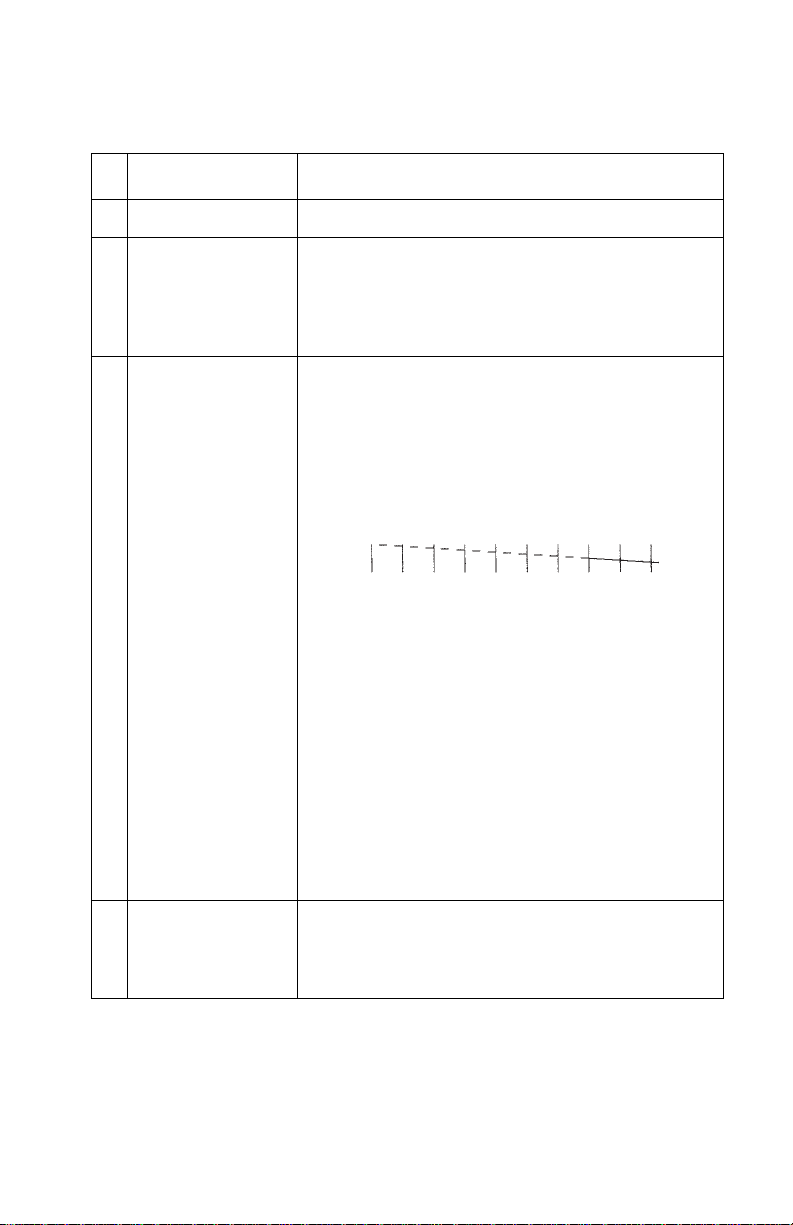
•Performthe’Test Page’on page 3-7. Look for a
break in the diagonal line of the test pattern. A
broken line indicates one or more print nozzles
are not working. Run the test again to verify the
failure. If there are even breaks in the diagonal
line similar to the pattern shown below, replace
the system board.
If there is a single break or random breaks in the
diagonal line check the following:
• Check the gold-plated contacts, on the end of
the cable that connect to the carrier, for dirt and
wear. Use only a clean dry cloth to clean the
contacts. Also check the cable for damage. You
mayneedtoremovethecablefromthecarrier
to inspect it.
• A worn rubber backer results in poor contact
between the printhead cable and the print
cartridge. Check the rubber backer for wear.
4 Maintenance
Station
Intermittent nozzle failures can be caused by worn
parts in the maintenance station. Perform the
’Maintenance Station Service Check’ on page 2-7,
then return to this check.
Diagnostic Information 2-12
Page 24

4090-001
FRU Action
5 Paper Feed Ink smudging and smearing can be caused by
paper problems or problems in the paper feed
area.
Check the following:
• Correct type of paper is being used. Also check
the paper for curl or wrinkles.
• Feed rollers for wear,dirt, or looseness.
• Gearsforwearorbinds.
• Paper path for obstructions.
6 Transport Blurred printand voids canbe caused byproblems
in the transport area. Check the following:
• Transport belt for wear.
• Carrier guide rod for wear or dirt.
• Carrier to carrier frame engagement should be
lubricated with grease P/N 1329301.
Do not lubricate the carrier guide rod or
carrier bearing surfaces.
• Idler pulley parts for wear, damage, or
looseness.
• Encoder strip for wear or dirt.
7 Alignment Uneven vertical lines can be adjusted by
performing the bidirectional alignment. The user is
directed, through the Printer Control program, to
perform thehead to head and bidirectional printing
alignments, when replacing a print cartridge.
2-13
Page 25

4090-001
Transport Service Check
FRU Action
1 Transport Motor Check the motor for binds, or loose motor pulley.
Disconnect the transport motor (J4) from the
system board. Check for 8 to 18 ohms between
pins 1 and 2 on the motor cable. If the reading is
incorrect, replace the motor.
Checkfor motorpins shorted to themotor housing.
If youfind a pinshorted to thehousing, replace the
motor. If the failure remains, replace the system
board.
2 System Board Turn the printer off and disconnect J4 from the
3 Carrier Guide Rod Clean the carrier rod.
4 Transport Belt
Idler Pulley Parts
Carrier Frame
5 Encoder Strip Check for wear and dirt.
6 Printhead Cable
Encoder Strip
Encoder Card
System Board
7 Maintenance
Station
system board. Turn the printer on and check for a
pulse of 6 to 8 V dc between J4-1 and ground as
the printer goes through POST.
Note: Do not lubricate the rod or the carrier rod
bearing surface.
Check for worn, loose or broken parts. Check for
obstructions blocking carrier movement.
Carrier to carrier frame engagement should be
lubricated with grease P/N 1329301.
Be sure connector J2 is fully seated. Check the
cable for damage.
Perform the ’Encoder Sensor Test’ on page 3-2.If
you cannot enter the test, replace the system
board.
A problemwith the maintenance station can cause
carrier movementproblems atthe right margin. Go
to the ’Maintenance Station Service Check’ on
page 2-7.
Diagnostic Information 2-14
Page 26

4090-001
3. Diagnostic Aids
Use these diagnostic test procedures to verify a repair. There are
two ways to enter test procedures, each procedure will indicate the
method to use:
Procedure 1:
• Press and hold the Paper Feed button while turning the
printer on. Release the button when the printer completes
POST.
Procedure 2:
• Turn the printer off.
• Use a two pin jumper on connector J6 as indicated, then turn
the printer on. The test begins when the power button is
pressed.
Note: You can use the two pin jumper on J7 to perform the tests.
Remember to return the jumper to J7 when the test is finished.
A two pin jumper is also available in the parts packet:
1367169 and 69G4188.
Diagnostic Aids 3-1
Page 27

4090-001
Encoder Sensor Test
This test disables the printer motors to allow you to manually move
the carrier to verify the encoder is working correctly.
To run the test:
1. Turn the printer off and place a two pin jumper on connector J6
as shown below. (Pins 1 & 2)
2. Press and hold the Paper Feed button while turning the
printer on, to star t the test. Release the button when the printer
completes POST. Turn power off or unplug the printer to stop
the test.
The power light flashes as the carrier is moved. The busy light
remains on for right to left, and blinks for left to right movement. With
no carrier movement, the busy light indicates the direction of the last
move. If the test fails, power off the printer and remove the carrier
assembly without unplugging the printhead cable.
Power on the printer and check for +5 V dc at pins 1, 2 and 3 of the
encoder card connector.
1. If voltage is not present, check the printhead cable for opens to
the encoder card. If the printhead cable is good, replace the
system board.
2. If voltage is present, check the sensor on the encoder card by
monitoring pin 3 of the encoder card connector as you pass a
piece of paper through the sensor. The voltage should go from
+5 V dc to 0 V dc. Turn the power off and back on to make this
check again. If the voltage at pin 3 does not change, replace the
encoder card. If the symptom remains, replace the printhead
cable.
Diagnostic Aids 3-2
Page 28

4090-0014090-001
Initialize Error Log
This test allows you to track new errors.
Use this procedure to reset the error log to zero. The error log is
especially helpful in diagnosing intermittent or difficult problems.
To run the test:
1. Turn the printer off and place a two pin jumper on connector J6
as shown below. (Pins 1 & 2)
2. Place a sheet of paper in the manual feed slot and press and
hold the paper feedbutton.Errors stored in NVRAM are erased.
Turn power off or unplug the pr inter to stop the test.
3-3
Page 29

4090-001
Paper Sensor Test
This test checks the paper sensor on the system board.
During the test, the power light remains on. The Busy light reflects
the paper sensor status in the following manner:
• On - paper is in sensor
• Off - paper is not in sensor
To run the test:
1. Turn the printer off and place a two pin jumper on connector J6
as shown below. (Pins 3 & 4)
2. Press and hold the Paper Feed button while turning the
printer on, to star t the test. Release the button when the printer
completes POST. Turn power off or unplug the printer to stop
the test.
Diagnostic Aids 3-4
Page 30

4090-0014090-001
Parallel Port Test
This test performs a wrap around test between the printer parallel
port and the parallel port test connector.
This test requires a parallel port wrap plug. Install the wrap plug in
the parallel port before you start the test.
To run the test:
1. Turn the printer off and place a two pin jumper on connector J6
as shown (Pins 3 & 4).
2. Attach the wrap plug to the parallel port.
3. Turn the printer on.
The power light blinks while the test runs. The busy light turns on if
the test is successful. The busy light blinks or turns off if the test
fails.
3-5
Page 31

4090-001
Print NVRAM Contents
This test prints the contents of NVRAM in hexadecimal format.
To run the test:
1. Turn the printer off and place a piece of paper in the manual
paper slot.
2. Press and hold the Paper Feed button while turning the
printer on. Release the button when the printer completes
POST.
The test prints English for easy recognition. The following appears
on the right side of the printout:
• Device ID
The following appears below the printout:
• Code Level
• Last Error
• Page Count
• Code Level Date
Diagnostic Aids 3-6
Page 32

4090-0014090-001
Test Page
This test prints the test page.
To run a complete test page of black and color patterns, be sure the
print cartridges are in good condition. Install a blackprint cartridge in
the left side of the printhead cradle and a color print cartridge in the
right side.
To enter the test:
1. Turn the printer off.
2. Ensure the manual paper slot is empty.
3. Press and hold the Paper Feed button while turning the
printer on. Release the button when the printer completes
POST.
The test page will contain the following:
• Code level and date
• Nozzle test pattern for both cartridges
• Bidirectional alignment pattern
• Vertical and horizontal test patterns
• Purge test for both cartridges
3-7
Page 33

4090-001
4. Repair Information
This chapter explains how to make adjustments to the printer and
how to remove defective parts.
Note: Read the following before handling electronic parts. When
working on the printer, always unplug the printer from the wall outlet.
High voltage is present in the power supply as long as it is plugged
into the wall outlet.
Handling ESD-Sensitive Parts
Many electronic products use parts that are known to be sensitive to
electrostatic discharge (ESD). To prevent damage to ESD-sensitive
parts, follow the instructions below in addition to all the usual precautions, such as turning off power before removing logic boards:
• Keepthe ESD-sensitive part in its original shipping container(a special
“ESD bag”) until you are ready to install the part into the printer.
• Make the least-possible movements with your body to prevent an
increase of static electricity from clothing fibers, carpets, and furniture.
• Put the ESD wrist strap on your wrist. Connect the wrist band to the
system ground point. This discharges any static electricity in your body
to the printer.
• Hold the ESD-sensitive part by its edge connector shroud (cover); do
not touch its pins. If you are removing a pluggable module, use the correct tool.
• Do not place the ESD-sensitive part on the printer cover or on a metal
table; if you need to put down the ESD-sensitive part for any reason,
first put it into its special bag.
• Printer covers and metal tables are electrical grounds. They increase
the risk of damage because they make a discharge path from your
body through the ESD-sensitive part. (Large metal objects can be discharge paths without being grounded.)
• Prevent ESD-sensitive parts from being accidentally touched by other
personnel. Install printer covers when you are not working on the
printer, and do not put unprotected ESD-sensitive parts on a table.
• If possible, keep all ESD-sensitive parts in a grounded metal cabinet
(case).
• Be extracareful in working with ESD-sensitiveparts when cold weather
heating is used because low humidity increases static electricity.
Repair Information 4-1
Page 34

4090-001
Adjustments
The user is directed, in the Printer Control program, to perform the
head toheadand bidirectional alignment adjustments afterreplacing
a print cartridge.
Removal Procedures
The following procedures are arranged according to the name of the
printer part discussed. Unplug the power cord before removing any
parts.
Releasing Plastic Latches
Many of the parts are held in place with plastic latches. The latches
break easily; releasethemcarefully.Toremove suchparts, pressthe
hook end of the latch away from the part to which it is latched.
4-2
Hook
Never apply excessive force
when releasing the hook.
Page 35

4090-001
Base Assembly Removal
1. Remove the front cover.
2. Remove the r ear cover.
3. Disconnect the power supply connector at the system board.
4. Remove the two screws from the maintenance station
assembly. Pull up the right side of the mid frame assembly and
pull forward and remove the maintenance station assembly.
5. Remove the two screws securing the carrier frame to the base
cover.
6. Slide the printer off the base cover.
Carrier Belt Removal
1. Remove the front cover.
2. Remove the carrier assembly.
3. Push the idler pulley to the right to release the tension on the
belt and remove the belt.
Repair Information 4-3
Page 36

4090-001
Carrier Frame Assembly Removal
1. Remove the front cover.
2. Remove the rear cover.
3. Remove the base assembly.
4. Disconnect the paper feed motor connector from the system
board.
5. Remove the fourscrews[A] securing the carrier frame to the left
and right side frames and remove the carrier frame assembly.
4-4
Page 37

4090-001
Note: During reassembly:
1. Be sure the small feed roll spring extensions [B] are in the
groves of the small feed roll arms.
2. Be sure the short extensions of the two paper flap springs are
trapped under the carrier frame [C].
Carrier Transport Motor Removal
1. Remove the front cover.
2. Disconnect the transport motor connector from the system
board.
3. Remove the belt from the transport motor pulley.
4. Remove the two screws securing the transport motor to the
carrier frame and remove the motor. Note the routing of the
motor cable.
Repair Information 4-5
Page 38

4090-001
Code Module Removal
1. Remove the front cover.
2. Remove the rear cover.
3. Gently pry the Code Module from the system board noting the
position of the notch in the module. The notch is down.
Edge Guide Asm and Paper Load Shaft Removal
1. Remove the front cover.
2. Remove the rear cover.
3. Remove the paper load door and manual insert tray.
4. Remove the pick roll hub, shaft and envelope bucklers.
5. Remove the two screws from the right side frame.
6. Work the paper load shaft out of the side frames.
7. Pull up the bottom of the edge guides to separate them from the
top of the back plate and remove the assembly from the frames.
Note: When reinstalling, be sure the edge guide springs are turned
to the inside to maintain spring tension on the guides.
Encoder Card Removal
1. Remove the front cover.
2. Remove the printhead carrier assembly.
3. Disconnect the printhead cable from the encoder card.
4. Remove the screw from the encoder card and remove the card.
Encoder Strip Removal
1. Remove the front cover.
2. Remove the carrier assembly.
3. Gently release the tension on the encoder strip by flexing the
encoder strip tensioner and remove the encoder strip.
Note: When reinstalling the encoder strip, make sure the ends of
the strip are centered in their mounting notches and the strip does
not bind in the encoder card on the carrier.
4-6
Page 39

4090-001
Exit Drive Belt Removal
1. Remove the front cover.
2. Remove the r ear cover.
3. Remove the carrier frame assembly.
4. Remove the paper load door and manual insert tray.
5. Remove the small feed roll shaft.
6. Unlatch the left side of the exit roller shaft and work the belt off
the exit roller pulley.
7. Pull up the four clips securing the mid frame to the large feed
roll and work the mid frame out of both side frames.
8. Spread the right side frame apart far enough to allow removalof
the exit drive belt.
Exit Roller Removal
1. Remove the front cover.
2. Remove the two screws from the star roller assembly and
remove the assembly.
3. Unlatch the left side of the exit roller and remove the exit drive
belt from the exit roller pulley.
4. Remove the exit roller.
Feed Arm Assembly Removal
1. Remove the front cover.
2. Remove the r ear cover.
3. Remove the C-clip from the feed arm and remove the assembly.
Repair Information 4-7
Page 40

4090-001
Front Cover Removal
1. Place a screwdriver in slot [A] and release the cover latches.
2. Slide the cover forward and off the printer.
To reassemble:
1. Slide the cover over the matching pieces on the bottom cover.
2. Press in both sides opposite the cover latches until they latch.
Gutter Pad Removal
1. Remove the front cover.
2. Remove the rear cover.
3. Remove the base assembly.
4. Scrape the old gutter pad off the base.
4-8
Page 41

4090-001
Inside Idler Gears Removal
1. Remove the front cover.
2. Remove the r ear cover.
3. Remove the printer from the base assembly.
4. Remove the paper feed motor.
5. Gently pry the two idler gears from the left side frame. Be
careful not to break the locking tabs [A].
Repair Information 4-9
Page 42

4090-001
Large Feed Roll Removal
1. Remove the front cover.
2. Remove the rear cover.
3. Remove the carrier frame assembly.
4. Using a small screwdriver, break the four prongs off the
compound idler gear and remove the idler gear.
5. Remove the large feedroll from the mid frame by pulling it out of
the four mounting clips. Spread the right side frame and remove
the large feed roll.
Note: Install the compound idler gear after the printer is installed in
the base assembly.
4-10
Page 43

4090-001
Large Outside Gear Removal
1. Remove the front cover.
2. Remove the r ear cover.
3. Remove the paper load door and manual insert tray.
4. Remove the C-clip from the feed arm assembly and remove the
feed arm assembly.
5. Remove the C-clip from the left side of the pick roll shaft.
6. Pull the pick roll shaft out far enough to remove the large gear.
Note: Gently pull the feed arm guide [A] on the left side frame
forward, then remove the large gear.
Repair Information 4-11
Page 44

4090-001
Left Side Frame Assembly Removal
1. Remove the front cover.
2. Remove the rear cover.
3. Remove the carrier frame assembly.
4. Remove the paper load door and manual insert tray.
5. Using a small screwdriver, break the four prongs off the
compound idler gear [A] and remove the idler gear.
6. Remove the two screws [B] securing the left side frame to the
back plate. Slide the left side frame off the back plate. Note the
relationship of the parts.
Note: Install a new compound idler g ear [A] after the printer is
installed in the base assembly.
B
4-12
A
Page 45

4090-001
Maintenance Station Assembly Removal
1. Remove the front cover.
2. Remove the r ear cover.
3. Remove the two screws from the maintenance station
assembly, lift up the right side of the mid frame assembly and
slide the maintenance station assembly forward, out of the
printer.
Maintenance Wipers and Caps Removal
1. Remove the front cover.
2. Push the carrier to the left away from the maintenance station.
3. Gently pull the caps and wipers off their mountings.
Note: When reinstalling the caps, be sure the cap is positioned with
the locking tabs to the left and right before pushing them down on
their mounting posts. Be sure the wipers are completely seated.
Manual Insert Tray Removal
1. Remove the front cover.
2. Remove the r ear cover.
3. Remove the paper load door.
4. Spread the right side frame away from the manual insert tray
until the pins in the insert tray clear the frame.
5. Remove the manual insert tray from the left side frame.
Mid Frame Assembly Removal
1. Remove the front cover.
2. Remove the r ear cover.
3. Remove the carrier frame assembly.
4. Remove the paper load door and manual insert tray.
5. Remove the small feed roll shaft.
6. Unlatch the left side of the exit roller shaft and work the belt off
the exit roller pulley.
7. Pull up the four clips securing the mid frame to the large feed
roll and work the mid frame out of both side frames.
Repair Information 4-13
Page 46

4090-001
Paper Feed Motor Removal
1. Remove the front cover.
2. Remove the rear cover.
3. Remove the base assembly.
4. Remove the two screws securing the paper feed motor and
remove the motor. Note the routing of the motor cable.
Paper Guide and EOF Flag Assembly Removal
1. Remove the front cover.
2. Remove the rear cover.
3. Remove the printhead carrier assembly.
4. Remove the carrier frame assembly.
5. Remove the encoder strip.
6. Remove the system board.
7. Remove the three small feed roll springs.
8. Push the locking tabs [A] to the rear and pull the paper guide
down and out of the carrier frame.
4-14
A
Page 47

4090-001
Note: During reassembly:
1. Be sure the small feed roll spring extensions [B] are in the
groves of the small feed roll arms.
2. Be sure the short extensions of the two paper flap springs are
trapped under the carrier frame [C].
Repair Information 4-15
Page 48

4090-001
Paper Load Door Removal
Spread the left side frame where it joins the paper load door and
remove the door.
Pick Roll Hub, Shaft and Envelope Bucklers Removal
1. Remove the front cover.
2. Remove the rear cover.
3. Remove the paper load door and manual insert tray.
4. Slide the left paper guide to the right.
5. Remove the C-clip from the left side of the pick roll shaft.
6. Pull the pick roll shaft out to the left and remove the pick roll
shaft, hubs and envelope bucklers.
Note: During reassembly, be sure the pick roll hubs are in the slots
at the bottom of the paper guides and the rolls are centered on the
pick pads.
Power Supply Removal
Note: When working on the printer, always unplug the printer from
the wall outlet. High voltage is present in the power supply as long
as it is plugged into the wall outlet.
1. Remove the front cover.
2. Remove the rear cover.
3. Remove the base assembly.
4. Turn the base over, pull out on the latches, slide the power
supply forward and off the base assembly.
4-16
Page 49

4090-001
Printhead Cable, Cradle & Paper Deflector Removal
1. Remove the front cover.
2. Remove the printhead carrier assembly.
3. Disconnect the printhead cablefrom the encoder card. Note the
routing of the cable under the retaining clip on the carrier.
4. Separate the cradle from the printhead carrier assembly by
pushing out the cradle latches [A].
5. Feed the folded end of the printhead cable through the opening
in the carrier assembly and remove the cable.
Note: Use the illustration to assemble thecarrier parts in the correct
sequence.
Repair Information 4-17
Page 50

4090-001
Note: Be sure the cable is secured under the three retaining clips
[B] on the back of the carrier.
B
4-18
Page 51

4090-001
Printhead Carrier Assembly Removal
1. Remove the front cover.
2. Unlock the two printhead cable connectors and disconnect the
printhead cable from the system board.
3. Remove the retainer from the right end of the carrier guide rod.
4. Slide the carrier guide rod to the left, out of the pr inter.
5. Lift the carrier out of the printer.
Printhead Rubber Backer Removal
1. Remove the front cover.
2. Remove the printhead carrier assembly.
3. Separate the cradle from the printhead carrier assembly by
pushing out the cradle latches [A].
4. Remove the rubber backer and paper deflector from under the
printhead carr ier cable.
Note: Use the illustration to assemble thecarrier parts in the correct
sequence.
Repair Information 4-19
Page 52

4090-001
Rear Cover Removal
1. Remove the front cover.
2. Place a screwdriver in slot [A] and release the cover latches.
A
3. Slide the cover up and off the printer.
4. To reassemble, place the cover over the tabs in the bottom
cover and press down until the coverlatches. Be sure the
parallel connector snaps do not get trapped behind the cover.
Right Side Frame Assembly Removal
1. Remove the front cover.
2. Remove the rear cover.
3. Remove the carrier frame assembly.
4. Remove the paper load door and manual insert tray.
5. Remove the two screws securing the right side frame to the
back plate.Slide the right side frame off the backplate. Note the
relationship of the parts.
4-20
A
Page 53

4090-001
Small Feed Roll Shaft, Rollers & Paper Flap Removal
1. Remove the front cover.
2. Remove the r ear cover.
3. Remove the carrier frame assembly.
4. Spread the left and right side frames apart far enough to
remove the small feed roll shaft assembly.
Boss Paper Guide Feature
Due to occasional paper buckling at the bottom edge of the page, a
new featurehas been added to the paper guide to stabilize the small
feed roll shaft. Install the new style paper guide and match the small
feed roll assembly. The new small feed roll FRU is cut out in the
paper flap allowing the new feature to contact the small feed roll
shaft.
Star Roller Removal
1. Remove the front cover.
2. Remove the two screws from the star roller assembly and
remove the assembly.
System Board Removal
1. Remove the front cover.
2. Unlock the two printhead cable connectors and disconnect the
printhead cables from the system board.
3. Disconnect the other cables from the system board.
4. Gently release the tension on the encoder strip by flexing the
encoder strip tensioner and remove the encoder strip from the
left side only.
5. Remove the three screws securing the system board to the
carrier frame and remove the system board. Note the routing of
the paper feed motor cable.
Note: The head to head and bidirectional printing alignments willbe
reset to factory defaults. The user, through the Printer Control
program, is directed to perform these alignments. When reinstalling
the system board, itiseasier to insert the printhead cables inthetwo
connectors prior to installing the board.
Repair Information 4-21
Page 54

4090-001
5. Connector Locations
The printer is shipped with the jumper pin setting in the following
static position. Be sure the jumper is installed on the correct pins.
Communications Jumper J7 pin 2 and 3.
Connector Locations 5-1
Page 55

4090-001
System Board Connectors
Connector Locations 5-2
Page 56

4090-001
Connector Connector Names
J1
J2
J3
J4
J5
J6
J7
J8
SW1
SW2
S1
U20
Printhead Cable 1
Printhead Cable 2
PowerSupply
Transport Motor
Paper Feed Motor
Test Jumper
Communications Jumper
Parallel Port
Paper Feed Switch
Power Switch
EOF Sensor
Code Module
Encoder Card Connector
5-3
Page 57

4090-001
6. Preventive Maintenance
This chapter contains the lubrication specifications. Follow these
recommendations to prevent problems and maintain optimum
performance.
Lubrication Specifications
Lubricate only when parts are replaced or as needed, not on a
scheduled basis. Use grease P/N 1329301 to lubricate the following:
• All gear mounting studs.
• The left and right ends of the large feed roller at the side frames.
• Both ends of the sheet feeder pick roll shaft at the side frames.
• The carrier to carrier frame engagement.
Do not lubricate the carrier guide rod, or carrier guide rod bearings.
Preventive Maintenance 6-1
Page 58

4090-001
7. Parts Catalog
How To Use This Parts Catalog
•
SIMILAR ASSEMBLIES: If two assemblies contain a majori ty of
identical parts, they are broken down on the same list. Common
parts are shown by one index number. Parts peculiar to one or
the other of the assemblies are listed separately and identified
by description.
• NS: (Not Shown) in the Asm-Index column indicates that the
part is procurable but is not pictured in the illustration.
• PP: in the parts descriptions column indicates the part is
available in the listed parts packet.
Parts Catalog 7-1
Page 59

4090-001
Assembly 1: Covers
Parts Catalog 7-2
Page 60

4090-001
AsmIndex
1 -1 70G0594 1 Base Asm includes Exit Tray, Gutter
-2 70G0595 1 FrontCover Asm,Access Cover,Button
-3 69G4118 1 Rear Cover
-4 69G4119 1 Gutter Pad, Base Asm
N/S 70G0591 1 Replaceable Package B/M (US)
N/S 70G0592 1 Replaceable Package B/M (Non - US)
Part
Number
Units Description
Pad, Feet
& LED Lens
Includes:(Carton, Cushion Set,Sealing
Tape)
Includes:(Carton, Cushion Set,Sealing
Tape)
7-3
Page 61

4090-001
Assembly 2: Frames
Parts Catalog 7-4
Page 62

4090-001
AsmIndex
2 -1 69G4120 1 Left Side Frame Sub-Asm without
-2 70G0574 1 Mid Frame with Star Rollers
-3 69G4121 1 Right Side Frame
-4 69G4122 1 Carrier Frame
-5 69G4188 4 Screw, Frame Mounting (PP)
Part
Number
Units Description
Gears
Also order gears B/M 69G4127
7-5
Page 63

4090-001
Assembly 3: Paper Feed
Parts Catalog 7-6
Page 64

4090-001
AsmIndex
3 -1 69G4074 1 Paper Guide Asm includes EOF
-1 70G3039 1 Paper Guide Asm includes EOF
-2 13A1196 1 Small Feed Roll Shaft Roll B/M
-3 70G0574 1 Star Roller Asm
-4 70G0575 1 Large Feed Roll Asm (includes
-5 70G0576 1 Paper Feed Motor, Motor Gear,
-6 69G4127 1 Gears B/M
-7 69G4398 1 Feed Arm Asm
Part
Number
Units Description
Flag, Spring (Old style - works
with old or new small feed roll).
See “Boss Paper Guide Feature”
on page 4-21.
Flag,Spring(Newstyle,works
with new small feed roll only). See
“Boss Paper Guide Feature” on
page 4-21.
and Paper Flap
(part of Mid Frame)
Small Compound Idler Gear)
Toroid
-8 69G4188 2 C-Clip (PP)
-9 69G4188 3 Spring, Small Feed Roll (PP)
-10 69G4188 2 Screw,Paper Feed Motor Mounting (PP)
-11 70G0577 1 ExitRoller
-12 70G0579 1 ExitDrive Belt
7-7
Page 65

4090-001
Assembly 4: Electronics
Parts Catalog 7-8
Page 66

4090-001
AsmIndex
Part
Number
Units Description
4 -1 70G2695 1 System Board, W/O Code Module
If code module in old board is labeled:
70G0830 through 70G0835;
70G0841 through 70G0845,70G2562,
70G2587, 70G2598, 70G2599, order
new code module 70G3000.
-2 70G0581 1 Power Supply with Ground Plane,
Insulator, Cover
-3 1339526
1342514
1339520
1339520
1342514
1342514
1342534
1339526
1342534
1342514
1342514
1339525
1342514
1339519
1342514
1339520
1339520
1339520
1342514
1342514
1339521
1339524
1342514
1339520
1342514
1339520
1342514
1342536
1342514
1339517
1339523
1339520
1339520
1339522
1339519
1342536
1342514
1PowerCord,U.S.
Power Cord, Argentina
Power Cord, Austria
Power Cord, Belgium
Power Cord, Bolivia
Power Cord, Brazil (LV)
Power Cord, Brazil (HV)
Power Cord, Canada
Power Cord, Chile
Power Cord, Columbia
Power Cord, Costa Rica
Power Cord, Denmark
Power Cord, Ecuador
Power Cord, Egypt
Power Cord, El Salvador
Power Cord, Finland
Power Cord, France
Power Cord, Germany
Power Cord, Guatemala
Power Cord, Honduras
Power Cord, Israel
Power Cord, Italy
Power Cord, Mexico
Power Cord, Netherlands
Power Cord, Nicaragua
Power Cord, Norway
Power Cord, Panama
Power Cord, Paraguay
Power Cord, Peru
Power Cord, Saudi Arabia
Power Cord, South Africa
Power Cord, Spain
Power Cord, Sweden
Power Cord, Switzerland
Power Cord, United Kingdom
Power Cord, Uruguay
Power Cord, Venezuela
7-9
Page 67

4090-001
Assembly 4: Electronics (continued)
Parts Catalog 7-10
Page 68

4090-001
AsmIndex
4 -4 70G3000 1 Code Module
-5 69G4188 5 Screw, System Board Mounting
NS 69G4188 1 Screw, Ground Jumper Mounting
NS 69G4188 2 Jumper, 2-Pin (PP)
Part
Number
Units Description
(PP)
(PP)
7-11
Page 69

4090-001
Assembly 5: Carrier
Parts Catalog 7-12
Page 70

4090-001
AsmIndex
5 -1 70G0585 1 Printhead Carrier B/M
-2 70G0586 1 Printhead Cable (Folded)
-3 70G0587 1 Rubber Backer
-4 69G4157 1 Carrier Guide Rod
-5 69G4156 1 Encoder Card Asm
-6 69G4188 1 Screw, Encoder Card Mounting
-7 69G4188 1 Retainer Right, Carrier Guide Rod
-8 69G4188 1 E-Ring, Carrier Guide Rod (PP)
-9 70G0588 1 Printhead Cartridge Interlock Key
Part
Number
Units Description
(PP)
(PP)
B/M
7-13
Page 71

4090-001
Assembly 6: Carrier Transport
4
2
1
6
3
5
Parts Catalog 7-14
Page 72

4090-001
AsmIndex
6 -1 69G4158 1 Carrier Transport Motor & Pulley
-2 69G4159 1 Carrier Belt
-3 69G4403 1 Encoder Strip
-4 69G4163 1 Idler Pulley Tension Asm
-5 69G4188 2 Screw, Carrier Transport Motor
-6 69G4188 1 Tensioner, Encoder Strip (PP)
Part
Number
Units Description
Mounting (PP)
7-15
Page 73

4090-001
Assembly 7: Sheet Feeder
Parts Catalog 7-16
Page 74

4090-001
AsmIndex
7 -1 69G4166 1 Right Edge Guide & Width Adjust
-2 69G4167 1 Left Edge Guide
-3 69G4131 1 Upper Paper Support
-4 1367469 1 Pick Roll & Paper Load Shaft B/M
-5 1367463 2 Pick Roll Hub Asm
-6 1367019 1 Envelope Buckler B/M, Left & Right
-7 69G4169 1 Back Plate
-8 69G4164 1 Paper Load Door Asm
-9 69G4165 1 Manual Insert Tray
-10 69G4127 1 Gear, Paper Load (Gears B/M)
-11 69G4188 1 E-Ring (PP)
-12 69G4188 4 Screw, Side Frame (PP)
-13 69G4188 1 Spring, Left Paper Load (PP)
Part
Number
Units Description
Strip
Includes Left Edge Guide
-14 69G4188 1 Spring, Right Paper Load (PP)
7-17
Page 75

4090-001
Assembly 8: Maintenance Station
Parts Catalog 7-18
Page 76

4090-001
AsmIndex
8 -1 70G0589 1 Maintenance Station Asm
-2 70G0590 1 Wiper and Cap B/M (one of each)
-3 69G4188 1 Screw, Maintenance Station
Part
number
Units Description
Mounting (PP)
7-19
Page 77

4090-001
Index 3
A
Abbreviations 1-2
Adjustments 4-2
Assemblies
1 Covers
2Frames7-4
3 Paper Feed 7-6
4 Electronics 7-8
5 Carrier 7-12
6 Carrier Transport 7-14
7 Sheet Feeder 7-16
8 Maintenance Station 7-18
7-2
C
Connector Locations 5-1
Connectors
System Board
5-2
D
Diagnostic Aids 3-1
Diagnostic Information 2-1
E
Error Indicator Table 2-2
ESD-Sensitive Parts 4-1
G
General Information 1-1
L
Lubrication Specifications 6-1
M
Maintenance Approach 1-1
P
Parts Catalog 7-1
Plastic Latches 4-2
POST
Sequence
Symptom Table 2-3
Power Consumption 1-1
Preventive Maintenance 6-1
Problems
Carrier Transport
Communications 2-4
Maintenance Station 2-4
Paper Feed 2-5
Power 2-5
Print Quality 2-5
2-2
2-4
R
Removals
Base Assembly
Carrier Belt 4-3
Carrier Frame 4-4
Carrier Transport Motor 4-5
Code Module 4-6
Edge Guide Asm 4-6
Encoder Card 4-6
Encoder Strip 4-6
Envelope Bucklers 4-16
EOF Flag Asm 4-14
Exit Drive Belt 4-7
Exit Roller 4-7
Feed Arm Assembly 4-7
Front Cover 4-8
Gutter Pad 4-8
Inside Idler Gears 4-9
Large Feed Roll 4-10
Large Outside Gear 4-11
Left Side Frame 4-12
Maintenance Caps 4-13
Maintenance Station 4-13
Maintenance Wipers 4-13
Manual Insert Tray 4-13
Mid Frame Assembly 4-13
Paper Deflector 4-17
Paper Feed Motor 4-14
Paper Flap 4-21
Paper Guide 4-14
4-3
X-1
Page 78

4090-001
Removals Continued
Paper Load Door
Paper Load Shaft 4-6
Pick Roll Hub 4-16
Pick Roll Shaft 4-16
Power Supply 4-16
Printhead Cable 4-17
Printhead Carrier 4-19
Printhead Cradle 4-17
Printhead Rubber Backer 4-19
Rear Cover 4-20
Right Side Frame 4-20
Small Feed Roll Shaft 4-21
Small Feed Rollers 4-21
Star Roller 4-21
System Board 4-21
Repair Information 4-1
4-16
S
Safety Information vi
Service Checks
Envelope Feed
First Print Line 2-6
Maintenance Station 2-7
Paper Feed 2-8
Paper Path 2-10
Parallel Port 2-11
Power 2-11
Print Quality 2-12
Transport 2-14
Start 2-1
Symptom Table (POST) 2-3
Symptom Tables 2-4
2-6
T
Tests
Encoder Sensor
Initialize Error Log 3-3
Parallel Port 3-5
Print NVRAM Contents 3-6
Test Page 3-7
Tools 1-2
X-2
3-2
 Loading...