

Page 1
RT-10
Universal Disc Player
User Guide
Page 2
READ INSTRUCTIONS – All the safety and operating instructions
should be read before the product is operated.
RETAIN INSTRUCTIONS – The safety and operating instructions
should be retained for future reference.
HEED WARNINGS – All warnings on the product and in the operating
instructions should be adhered to.
FOLLOW INSTRUCTIONS – All operating and use instructions
should be followed.
CLEANING – Unplug this product from the wall outlet before cleaning.
The product should be cleaned only with a polishing cloth or a soft
dry cloth. Never clean with furniture wax, benzine, insecticides or
other volatile liquids since they may corrode the cabinet.
ATTACHMENTS – Do not use attachments not recommended by the
product manufacturer as they may cause hazards.
WATER AND MOISTURE – Do not use this product near water – for
example, near a bathtub, wash bowl, kitchen sink, or laundry tub;
in a wet basement; or near a swimming pool; and the like.
ACCESSORIES – Do not place this product on an unstable cart,
stand, tripod, bracket, or table. The product may fall, causing
serious injury to a child or adult, and serious damage to the
product. Use only with a cart, stand, tripod, bracket, or table
recommended by the manufacturer, or sold with the product. Any
mounting of the product should follow the manufacturer’s
instructions, and should use a mounting accessory recommended
by the manufacturer.
CART – A product and cart combination should be moved with care.
Quick stops, excessive force, and uneven surfaces may cause the
product and cart combination to overturn.
POWER SOURCES – This product should be operated only from the
type of power source indicated on the marking label. If you are not
sure of the type of power supply to your home, consult your product
dealer or local power company.
LOCATION – The appliance should be installed in a stable location.
NONUSE PERIODS – The power cord of the appliance should be
unplugged from the outlet when left unused for a long period of time.
GROUNDING OR POLARIZATION
• If this product is equipped with a polarized alternating current line
plug (a plug having one blade wider than the other), it will fit into the
outlet only one way.This is a safety feature. If you are unable to insert
the plug fully into the outlet, try reversing the plug. If the plug should
still fail to fit, contact your electrician to replace your obsolete outlet.
Do not defeat the safety purpose of the polarized plug.
• If this product is equipped with a three-wire grounding type plug, a
plug having a third (grounding) pin, it will only fit into a grounding-type
power outlet. This is a safety feature. If you are unable to insert the
plug into the outlet, contact your electrician to replace your obsolete
outlet. Do not defeat the safety purpose of the grounding type plug.
POWER CORD PROTECTION – Power-supply cords should be routed
so they are not likely to be walked on or pinched by items placed
upon or against them, paying particular attention to cords at plugs,
convenience receptacles, and the point where they exit from the
product.
LIGHTNING – For added protection for this product during a lightning
storm, or when it is left unattended and unused for long periods of
time, unplug it from the wall outlet and disconnect the antenna or
cable system. This will prevent damage to the product due to lightning
and power line surges.
POWER LINES – An outside antenna system should not be located in
the vicinity of overhead power lines or other electric light or power
circuits, or where it can fall into such power lines or circuits. When
installing an outside antenna system, extreme care should be taken
to keep from touching such power lines or circuits as contact with
them might be fatal.
OVERLOADING – Do not overload wall outlets, extension cords, or
integral convenience receptacles as this can result in a risk of fire or
electric shock.
OBJECT AND LIQUID ENTRY – Never push objects of any kind into
this product through openings as they may touch dangerous
voltage points or short-out parts that could result in a fire or
electric shock. Never spill liquid of any kind on the product.
SERVICING – Do not attempt to service this product yourself as
opening or removing covers may expose you to dangerous
voltage or other hazards. Refer all servicing to qualified service
personnel.
DAMAGE REQUIRING SERVICE – Unplug this product from the wall
outlet and refer servicing to qualified service personnel under the
following conditions:
• When the power-supply cord or plug is damaged.
• If liquid has been spilled, or objects have fallen into the product.
• If the product has been exposed to rain or water.
• If the product does not operate normally by following the
operating instructions. Adjust only those controls that are covered
by the operating instructions as an improper adjustment of other
controls may result in damage and will often require extensive
work by a qualified technician to restore the product to its normal
operation.
• If the product has been dropped or damaged in any way.
• When the product exhibits a distinct change in performance – this
indicates a need for service.
REPLACEMENT PARTS – When replacement parts are required, be
sure the service technician has used replacement parts specified
by the manufacturer or have the same characteristics as the
original part. Unauthorized substitutions may result in fire, electric
shock, or other hazards.
SAFETY CHECK – Upon completion of any service or repairs to this
product, ask the service technician to perform safety checks to
determine that the product is in proper operating condition.
WALL OR CEILING MOUNTING – The product should not be
mounted to a wall or ceiling.
HEAT – The product should be situated away from heat sources such
as radiators, heat registers, stoves, or other products (including
amplifiers) that produce heat.
IMPORTANT SAFETY INSTRUCTIONS
This triangle, which appears on your component,
alerts you to the presence of uninsulated,
dangerous voltage inside the enclosure -
voltage that may be sufficient to
constitute a risk of shock.
CAUTION
RISK OF ELECTRIC SHOCK
DO NOT OPEN
This triangle, which appears on your component,
alerts you to important operating and
maintenance instructions in this
accompanying literature.
CAUTION: TO REDUCE THE RISK OF ELECTRIC SHOCK, DO NOT REMOVE THE COVER (OR BACK)
NO USER-SERVICEABLE PARTS INSIDE
REFER SERVICING TO QUALIFIED SERVICE PERSONNEL
VENTILATION – Slots and openings in the cabinet are provided for
ventilation and to ensure reliable operation of the product and to
protect it from overheating, and these openings must not be
blocked or covered. The openings should never be blocked by
placing the product on a bed, sofa, rug, or other similar surface.
This product should not be placed in a built-in installation such as
a bookcase or rack unless proper ventilation is provided or the
manufacturer’s instructions have been adhered to.
Page 3
BEFORE PLUGGING IN THE UNIT FOR THE FIRST TIME,
READ THE FOLLOWING SECTION CAREFULLY: THE
AVAILABLE POWER SUPPLY VOLTAGE DIFFERS AMONG
COUNTRIES AND REGIONS. MAKE SURE THE POWER
SUPPLY VOLTAGE OF THE AREA WHERE THIS UNIT WILL
BE USED MEETS THE REQUIRED VOLTAGE (E.G., 230V
OR 120V) WRITTEN ON THE REAR PANEL.
WARNING
TO REDUCE THE RISK OF FIRE OR ELECTRIC SHOCK,
DO NOT EXPOSE THIS UNIT TO RAIN OR MOISTURE.
• Do not remove the cover from the unit.
• Do not insert anything into the unit through the ventilation
holes.
• Do not handle the mains lead with wet hands.
• Make a space of about .33ft (0.1m) around the unit.
WARNING
Slots and openings on the case are provided for ventilation.To
ensure reliable operation of the unit, to protect it from
overheating, and to prevent fire hazard, these openings must
not be blocked or covered with items such as newspapers,
table cloths, or curtains. In addition, do not place the unit on a
thick carpet, bed, sofa, or fabric with a thick pile.
WARNING
DO NOT PLACE NAKED FLAME SOURCES, SUCH AS LIT
CANDLES, ON THE UNIT. NAKED FLAME SOURCES
MIGHT ACCIDENTALLY FALL DOWN, CAUSING FIRE TO
SPREAD OVER THE UNIT.
WARNING
• Use of controls or adjustments or performance of
procedures other than those specified herein may result
in hazardous radiation exposure.
• The use of optical instruments with this product will
increase eye hazard.
CAUTION
LASER SAFETY:This unit employs a LASER. Only a qualified
person should remove the cover or attempt to service this
device, due to possible eye injury.
CAUTION
FOR CANADIAN MODEL:
This Class B digital apparatus complies with Canadian ICES-003.
POUR LE MODELE CANADIEN:
Cet appareil numérique de la Classe B est conforme à la norme NMB-003 due
Canada.
ATTENTION:
POUR ÉVITER LES CHOCS ÉLECTRIQUES INTRODUIRE LA LAME LA
PLUS LARGE DE LA FICHE DANS LA BORNE CORRESPON-DANTE DE LA
PRISE ET POUSSER JUSQU’AU FOND.
Page 4
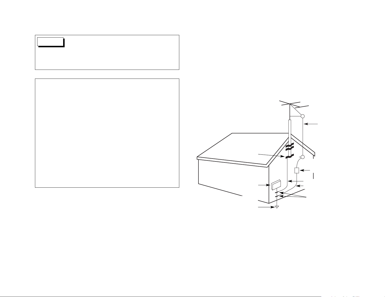
OUTDOOR ANTENNA GROUNDING
If an outside antenna or cable system is connected to the product, be sure the
antenna or cable system is grounded so as to provide some protection against
voltage surges and built-up static charges. Article 810 of the National Electrical
Code, ANSI/NFPA 70, provides information with regard to proper grounding of the
mast and supporting structure, grounding of the lead-in wire to an antenna
discharge unit, size of grounding conductors, location of antenna-discharge unit,
connection to grounding electrodes, and requirements for the grounding electrode.
See Figure A below.
Figure A
Antenna LeadIn Wire
Antenna Discharge
Unit (NEC* Section
810-20)
Grounding Conductors
(NEC* Section 810-21)
Electric Service
Equipment
* National Electrical Code
Power Service Grounding
Electrode System
(NEC* Art 250, Part H)
Ground Clamps
Ground Clamp
This equipment has been tested and found to comply with the limits for a
Class B digital device, pursuant to Part 15 of the FCC Rules. These limits are
designed to provide reasonable protection against harmful interference in a
residential installation.This equipment generates, uses, and can radiate radio
frequency energy and, if not installed and used in accordance with the
instructions, may cause harmful interference to radio communications.
However, there is no guarantee that interference will not occur in a particular
installation. If this equipment does cause harmful interference to radio or
television reception, which can be determined by turning the equipment off
and on, the user is encouraged to try to correct the interference by one or
more of the following measures:
• Reorient or relocate the receiving antenna.
• Increase the separation between the equipment and receiver.
• Connect the equipment into an outlet on a circuit different from that to
which the receiver is connected.
• Consult the dealer or an experienced radio/TV technician for help.
This product satisfies FCC regulations when shielded cables
and connectors are used to connect the unit to other
equipment. To prevent electromagnetic interference with
electric appliances such as radios and televisions, use
shielded cables and connectors for connections.
CAUTION
Page 5
Appears on your component to alert you to the presence of
uninsulated, dangerous voltage inside the enclosure…voltage
that may be sufficient to constitute a risk of shock.
Appears on your component to alert you to important
operating and maintenance instructions in this accompanying
literature.
WARNING
CAUTION
Manufactured under license from Dolby Laboratories. "Dolby," "Pro Logic," "Surround EX," and the double-D symbol are trademarks of Dolby Laboratories.
Manufactured under license from Digital Theater Systems, Inc. U.S. Pat. No. 5,451,942, 5,956,674, 5,974,380, 5,978,762, and other world-wide patents issued and
pending. "DTS" and "DTS Digital Surround" are registered trademarks of Digital Theater Systems, Inc. © 1996, 2000 Digital Theater Systems, Inc. All rights reserved.
This product incorporates copyright protection technology that is protected by method claims of certain U.S. patents and other intellectual property rights owned by
Macrovision Corporation and other rights owners. Use of this copyright protection technology must be authorized by Macrovision Corporation, and is intended for home
and other limited viewing uses only unless otherwise authorized by Macrovision Corporation. Reverse engineering or disassembly is prohibited.
© 2003 Lexicon, Inc. All rights reserved.
This document should not be construed as a commitment on the part of Lexicon, Inc. The information it contains is subject to change without notice. Lexicon, Inc.
assumes no responsibility for errors that may appear within this document.
Lexicon, Inc.
3 Oak Park
Bedford, MA 01730-1413 USA
Tel 781-280-0300
Fax 781-280-0490
www.lexicon.com
Customer Support
Tel 781-280-0300
Fax 781-280-0495 (Sales)
Fax 781-280-0499 (Service)
Lexicon Part No. 070-15658 | Rev 0 | 01/03
DOCUMENTATION CONVENTIONS
This document contains general safety, installation, and operation instructions for the RT-10 Universal Disc Player. It is important to read this user guide before operating this
product. Pay particular attention to safety instructions.
The following symbols are used in this document:
Calls attention to a procedure, practice, condition or the like
that, if not correctly performed or adhered to, could result in
injury or death.
Calls attention to a procedure, practice, condition or the like
that, if not correctly performed or adhered to, could result in
damage or destruction to part or all of the product.
Note: Calls attention to information that is essential to highlight.
• This document uses the term “DVD” to refer to DVD-V, DVD-A, DVD-RW, and DVD-R formats. Otherwise, this document uses the term DVD-V to refer to DVD Video format, DVD-A to refer to DVD
Audio format, and DVD-RW/R to refer to DVD-RW and DVD-R formats.
• This document uses the term “CD” to refer to Audio CD, CD-RW, CD-R, and Video CD formats. Otherwise, this document uses the term Audio CD to refer to Audio CD format, CD-RW/R to refer
to CD-RW and CD-R formats, and Video CD to refer to Video CD format.
• This document uses the term “MP3” to refer to CD-RW/R formats that include MP3 tracks.
Page 6

Introduction
Lexicon
iv
Section 1: Getting Started
About the RT-10 . . . . . . . . . . . . . . . . . . . . . . . . . . . . . . . . . . 1-2
Highlights • Product Registration
Installation Considerations. . . . . . . . . . . . . . . . . . . . . . . . . . . 1-3
Do . . . • Do Not . . .
DVD-V Regions. . . . . . . . . . . . . . . . . . . . . . . . . . . . . . . . . . . 1-4
Disc Compatibility . . . . . . . . . . . . . . . . . . . . . . . . . . . . . . . . 1-5
Discs to Avoid
Disc Care & Handling . . . . . . . . . . . . . . . . . . . . . . . . . . . . . . 1-8
Do . . . • Do Not . . .
Remote Control Battery Installation . . . . . . . . . . . . . . . . . . . . 1-9
Section 2: Basic Operation
Front Panel Overview . . . . . . . . . . . . . . . . . . . . . . . . . . . . . . 2-2
Front Panel Display Indicators
Rear Panel Overview . . . . . . . . . . . . . . . . . . . . . . . . . . . . . . . 2-8
Rear Panel Connections
Remote Control Overview . . . . . . . . . . . . . . . . . . . . . . . . . . 2-14
Operation Considerations • Command Matrix
Section 3: Setup Menus
Control Bar. . . . . . . . . . . . . . . . . . . . . . . . . . . . . . . . . . . . . . 3-2
Setup Navigator . . . . . . . . . . . . . . . . . . . . . . . . . . . . . . . . . . 3-2
Setup Menu . . . . . . . . . . . . . . . . . . . . . . . . . . . . . . . . . . . . . 3-9
Audio1 • Audio2 • Video1 • Video2 • Language • General
Setup Menu Shortcuts. . . . . . . . . . . . . . . . . . . . . . . . . . . . . 3-50
Advanced Setup Menu . . . . . . . . . . . . . . . . . . . . . . . . . . . . 3-51
Introduction
Documentation Conventions . . . . . . . . . . . . . . . . . . . . . . . . . . iii
Important Safety Instructions. . . . . . . . . . . . . . . . . . . . . vi
Wichtige Sicherheitshinweise . . . . . . . . . . . . . . . . . . . . . vi
Instrucciones de seguridad importantes. . . . . . . . . . . . . vii
Instructions importantes relatives à la sécurité . . . . . . . . vii
Importanti norme di sicurezza . . . . . . . . . . . . . . . . . . . viii
Instruções Importantes de Segurança . . . . . . . . . . . . . . viii
Vigtig information om sikkerhed . . . . . . . . . . . . . . . . . . ix
Tärkeitä turvallisuusohjeita. . . . . . . . . . . . . . . . . . . . . . . ix
Viktig informasjon om sikkerhet . . . . . . . . . . . . . . . . . . . x
Viktiga säkerhetsföreskrifter . . . . . . . . . . . . . . . . . . . . . . x
Unpacking and Inspection. . . . . . . . . . . . . . . . . . . . . . . xi
Auspacken und Überprüfung . . . . . . . . . . . . . . . . . . . . . xi
Desembalaje e inspección . . . . . . . . . . . . . . . . . . . . . . . xi
Contenu de l’emballage et inspection . . . . . . . . . . . . . . xi
Disimballaggio ed ispezione . . . . . . . . . . . . . . . . . . . . . xi
Retirando a embalagem e Inspecionando . . . . . . . . . . . . xi
FR
IT
PT
ES
DE
US
DK
FI
NO
SE
FR
IT
PT
ES
DE
US
Page 7

Introduction
RT-10
v
Section 4: Playback Controls
Playback Icons . . . . . . . . . . . . . . . . . . . . . . . . . . . . . . . . . . . 4-2
Loading Discs . . . . . . . . . . . . . . . . . . . . . . . . . . . . . . . . . . . . 4-2
Navigating Disc Menus . . . . . . . . . . . . . . . . . . . . . . . . . . . . . 4-3
Selecting Disc Settings . . . . . . . . . . . . . . . . . . . . . . . . . . . . . 4-7
Audio Tracks • Subtitle Languages • Camera Angles • Storing Disc Settings
Playback Modes . . . . . . . . . . . . . . . . . . . . . . . . . . . . . . . . . 4-11
Playback • Last Memory Playback • Stop Mode • Resume Mode • Pause Mode •
Still Frame Playback • Frame-by-Frame Playback • Slow Playback • Random
Playback • Repeat Playback • A-B Repeat Playback • Program Mode • Search
Mode • Display Mode
Section 5: Troubleshooting & Maintenance
Troubleshooting . . . . . . . . . . . . . . . . . . . . . . . . . . . . . . . . . . 5-2
Power Issues • Remote Control Issues • Video Output Issues • Audio Output
Issues • Playback Issues • Setup Menu Issues • Playback Control Issues •
Miscellaneous Issues
RT-10 Maintenance . . . . . . . . . . . . . . . . . . . . . . . . . . . . . . . 5-15
Disc Maintenance . . . . . . . . . . . . . . . . . . . . . . . . . . . . . . . . 5-16
Restoring Factory-Default Settings . . . . . . . . . . . . . . . . . . . . 5-16
Appendix
Specifications . . . . . . . . . . . . . . . . . . . . . . . . . . . . . . . . . . . . A-2
Declaration of Conformity. . . . . . . . . . . . . . . . . . . . . . . . . . . A-3
Setup Menu Screens . . . . . . . . . . . . . . . . . . . . . . . . . . . . . . . A-4
Table of Languages & Language Codes . . . . . . . . . . . . . . . . A-14
Table of Country Codes . . . . . . . . . . . . . . . . . . . . . . . . . . . A-16
Installation Worksheet. . . . . . . . . . . . . . . . . . . . . . . . . . . . . A-17
Index. . . . . . . . . . . . . . . . . . . . . . . . . . . . . . . . . . . . . . . . . . I-1
Notes
Limited Warranty
. . . . . . . . . . . . . . . . . . . . Inside Back Cover
Page 8
Introduction
Lexicon
vi
ENGLISH
IMPORTANT SAFETY INSTRUCTIONS
• Save these instructions for later use.
• Follow all instructions and warnings marked on the unit.
• Always use with the correct line voltage. Refer to the manufacturer’s operating instructions
for power requirements. Be advised that different operating voltages may require the use
of a different line cord and/or attachment plug.
• Do not install the unit in an unventilated rack, or directly above heat producing equipment
such as power amplifiers. Observe the maximum ambient operating temperature listed in
the product specification.
• Slots and openings on the case are provided for ventilation; to ensure reliable operation
and prevent it from overheating, these openings must not be blocked or covered. Never
push objects of any kind through any of the ventilation slots. Never spill liquid of any kind
on the unit.
• Never attach audio power amplifier outputs directly to any of the unit’s connectors.
• To prevent shock or fire hazard, do not expose the unit to rain or moisture, or operate it
where it will be exposed to water.
• Do not attempt to operate the unit if it has been dropped, damaged, exposed to liquids, or
if it exhibits a distinct change in performance indicating the need for service.
• This unit should only be opened by qualified service personnel. Removing covers will
expose you to hazardous voltages.
This triangle, which appears on your component, alerts you to the presence of
uninsulated, dangerous voltage inside the enclosure…voltage that may be sufficient
to constitute a risk of shock.
This triangle, which appears on your component, alerts you to important operating
and maintenance instructions in this accompanying literature.
US
US
DEUTSCH
WICHTIGE SICHERHEITSHINWEISE
• Bewahren Sie diese Anleitungen zur späteren Benutzung auf.
• Befolgen Sie alle Anleitungen und alle Warnhinweise auf dem Gerät
• Betreiben Sie das Gerät immer mit der korrekten Netzspannung. Angaben über den
Strombedarf entnehmen Sie bitte den Betriebsanweisungen des Herstellers. Bei
unterschiedlichen Betriebsspannungen kann die Verwendung anderer Netzkabel und/oder
Anschlußstecker erforderlich werden.
• Bauen Sie das Gerät nie in ein unbelüftetes Rack oder direkt über Wärme erzeugenden
Geräten wie Verstärkern ein. Beachten Sie die in der Produktspezifikation aufgeführte
maximale Umgebungstemperatur für den Betrieb.
• Schlitze und Öffnungen in der Box dienen der Belüftung, damit das Gerät zuverlässig läuft
und sich nicht überhitzt. Diese Öffnungen dürfen nicht abgedeckt oder blockiert werden.
Auch dürfen keine Gegenstände in sie hineingesteckt werden. Verschütten Sie niemals
Flüssigkeiten, gleich welcher Art, auf das Gerät.
• Schließen Sie niemals Stromausgänge des Audioverstärkers direkt an das Gerät an.
• Zur Vermeidung von elektrischen Schlägen oder Brandgefahr darf das Gerät weder Regen
noch Feuchtigkeit ausgesetzt oder an Orten betrieben werden, wo es mit Wasser in
Berührung kommen kann.
• Versuchen Sie nie, das Gerät zu betreiben, wenn es fallen gelassen, beschädigt oder
Flüssigkeiten ausgesetzt wurde oder wenn ein deutlicher Leistungsunterschied zu
verzeichnen ist, der darauf hinweist, dass es gewartet werden muss.
• Dieser Apparat sollte nur von qualifizierten Fachleuten geöffnet werden. Das Abnehmen
von Abdeckungen setzt Sie gefährlichen Spannungen aus.
Dieses Dreieck, welches auf Ihrem Bauteil angebracht ist, warnt Sie vor dem
Vorhandensein nicht isolierter gef hrlicher Spannung im Ger t. Diese Spannung
kann so hoch sein, dass das Risiko eines Stromschlags besteht.
Dieses Dreieck, welches auf Ihrem Bauteil angebracht ist, macht Sie auf wichtige
Betriebs- und Wartungshinweise in diesen Hinweisen aufmerksam.
DE
DE
Page 9
Introduction
RT-10
vii
ESPAÑOL
INSTRUCCIONES DE SEGURIDAD IMPORTANTES
• Guarde estas instrucciones para futuras referencias.
• Siga todas las instrucciones y tenga en cuenta las advertencias que aparecen en la
unidad y en las instrucciones de funcionamiento.
• Utilice siempre la tensión de línea correcta. Consulte las instrucciones del fabricante,
donde se especifican los requisitos de alimentación. Tenga en cuenta que unas tensiones
operativas diferentes pueden precisar de la utilización de diferentes cables de
alimentación y/o enchufes.
• No instale la unidad en un rack sin ventilación, o directamente sobre equipos que generen
calor, como amplificadores de potencia. Tenga en cuenta la temperatura operativa
ambiental máxima que se detalla en las especificaciones del producto.
• Las ranuras y aberturas del equipo son para su ventilación - para garantizar un
funcionamiento fiable y evitar que la unidad se sobrecaliente, no bloquee, cubra o inserte
objetos en las aberturas. No derrame nunca líquidos de ningún tipo sobre la unidad.
• Nunca conecte directamente salidas de amplificadores de potencia de audio a ninguno de
los conectores de la unidad.
• Para evitar descargas eléctricas o incendios, no exponga la unidad a la humedad o la
lluvia, ni la utilice donde pueda estar expuesta al agua.
• No intente utilizar la unidad si ésta ha caído, se ha dañado, ha estado expuesta a líquidos,
o si muestra un cambio importante en sus prestaciones, lo cual indicaría la necesidad de
una reparación.
• Dieser Apparat sollte nur von qualifizierten Fachleuten geöffnet werden. Das Esta unidad
deberá ser abierta únicamente por personal calificado. Si usted quita las coberturas se
expondrá a voltajes peligrosos.
Este tri ngulo, que aparece en su componente, alerta de la presencia de una tensi
n peligrosa no aislada en el interior del equipo - una tensi n que puede ser suficiente
como para constituir un riesgo de descarga el ctrica.
Este tri ngjlo, que aparece en su equipo, le alerta de instrucciones operativas y de
mantenimiento importantes en los documentos que acompa an el producto.
ES
ES
FRANÇAIS
INSTRUCTIONS IMPORTANTES RELATIVES
À LA SÉCURITÉ
• Conservez ces instructions pour pouvoir vous y référer ultérieurement.
• Suivez toutes ces instructions et tenez compte de tous les avertissements indiqués sur
l’appareil et dans la documentation fournie avec l’appareil.
• Utilisez toujours la tension secteur correcte. Consultez les instructions du fabricant
précisant les caractéristiques d’alimentation à respecter. Attention, le type de cordon
secteur et/ou de prise secteur peut varier selon des tensions en vigueur dans l’installation.
• N’installez pas l’appareil dans un Rack mal ventilé ou directement au-dessus d’un appareil
dégageant de la chaleur comme un amplificateur de puissance. Respectez la température
maximale de fonctionnement précisée dans les caractéristiques techniques.
• Les ouvertures dans le boîtier assurent la bonne ventilation de l’appareil, évitent toute
surchauffe et assurent le bon fonctionnement du système. Veillez à ne pas obstruer,
couvrir ou insérer d’objets dans ces ouvertures. Veillez à ne pas renverser de liquide sur
l’appareil.
• Ne reliez jamais directement les sorties audio des amplificateurs de puissance aux
connecteurs de l’appareil.
• Afin d’éviter tout risque d’électrocution ou d’incendie, n’exposez pas l’appareil à la pluie
ou à l’humidité ; ne l’utilisez pas dans des endroits exposés aux projections de liquides.
• N’essayez pas d’utiliser l’appareil si celui-ci est tombé, a été endommagé, exposé à des
projections de liquides ou si vous constatez des dysfonctionnements nécessitant
l’intervention d’un technicien spécialisé.
• Cet appareil ne doit être ouvert que par un personnel de service qualifié. En enlevant les
couvercles vous vous exposez à des tensions électriques dangereuses.
Le symbole de l’ clair fl ch dans un triangle quilat ral sert alerter l’utilisateur sur la pr
sence l’int rieur de l’appareil de tensions non isol es susceptibles de constituer un
risque d’ lectrocution.
Le point d’exclamation dans un triangle quilat ral sert alerter l’utilisateur sur la pr
sence de nombreuses instructions de maintenance dans le manuel fourni avec
l’appareil.
FR
FR
Page 10
Introduction
Lexicon
viii
ITALIANO
IMPORTANTI NORME DI SICUREZZA
• Conservare le presenti norme per l’utilizzo futuro.
• Seguire sempre tutte le istruzioni e gli avvertimenti segnati sull’unità e nelle istruzioni
operative.
• Utilizzare sempre la corretta tensione di alimentazione. Fare riferimento al manuale del
costruttore per le caratteristiche di alimentazione. Tensioni di rete diverse necessitano
anche di un diverso cavo con spine differenti.
• Non installare l’unità in un rack poco ventilato, o direttamente sopra apparecchiature che
producono calore, come amplificatori di potenza. Controllare la massima temperatura
ambientale di esercizio sulle specifiche tecniche del prodotto.
• Fori ed aperture nei pannelli sono necessari per garantire un corretta ventilazione e
prevenire surriscaldamenti. Queste aperture non devono essere coperte o ostruite. Non
inserire oggetti di alcun tipo nei fori di ventilazione. Evitare il contatto con liquidi di
qualsiasi genere.
• Evitare di collegare le uscite di un amplificatore di potenza direttamente a qualsiasi
connettore dell’unità.
• Per evitare il rischio di scosse elettriche non esporre il prodotto a pioggia o umidità. Evitare
l’uso dove possa essere esposto all’acqua.
• Non tentare di utilizzare il prodotto se è caduto, se è stato a contatto con liquidi, o mostra
chiari segni di danneggiamento o cambio di prestazioni che indicano la necessità di
assistenza tecnica.
• Ogni intervento sull’unità va eseguito esclusivamente da personale qualificato. La
rimozione della copertura comporta l’esposizione al pericolo di folgorazione.
Il presente triangolo impresso sul componente avverte la presenza di tensioni
pericolose non isolate all interno della copertura – tali tensioni rappresentano un
pericolo di folgorazione.
Il presente triangolo impresso sul componente avverte l utente della presenza nella
documentazione allegata di importanti istruzioni relative al funzionamento ed alla
manutenzione.
IT
IT
PORTUGUESE
INSTRUÇÕES IMPORTANTES DE SEGURANÇA
• Guarde essas instruções para uso posterior.
• Siga todas as instruções e fique atento aos avisos marcados na unidade e nas instruções
de operação.
• Sempre use com a voltagem correta. Veja no manual de instruções do fabricante qual a
alimentação necessária. Lembre-se que voltagens de operação diferentes podem
precisar de um cabo ou plug diferentes.
• Não instale a unidade em um suporte sem ventilação ou diretamente acima de
equipamentos que produzam calor, como transformadores. Observe a temperatura
ambiente máxima de operação indicada na especificação do produto.
• O revestimento da unidade é provido de fendas e aberturas para ventilação – para
assegurar uma operação confiável e evitar que a unidade se superaqueça.Não bloqueie,
cubra ou insira objetos nas aberturas. Nunca derrube líquido de qualquer espécie na
unidade.
• Nunca ligue saídas de amplificadores de áudio diretamente a qualquer dos conectores da
unidade.
• Para evitar danos de choque ou fogo, não exponha a unidade à chuva ou umidade, ou
opere-a onde haja exposição à água.
• Não tente operar a unidade se ela for derrubada, danificada, exposta à líquidos ou
apresente uma mudança de performance notável, indicando a necessidade de
manutenção.
• Esta unidade só deveria ser aberta através de pessoal de serviço qualificado. Removendo
coberturas o exporão a voltagens perigosas.
Esse triângulo que aparece no seu console, alerta para a presença de voltagem
perigosa e não isolada no recinto – voltagem que pode ser suficiente para constituir
um risco de choque.
Esse triângulo ques aparece no seu console alerta para instruções importantes de
operação e manutenção neste manual.
PT
PT
Page 11
Introduction
RT-10
ix
DANSK
VIGTIG INFORMATION OM SIKKERHED
• Gem denne vejledning til senere brug.
• Følg alle anvisninger og advarsler på apparatet.
• Apparatet skal altid tilsluttes den korrekte spænding. Der henvises til brugsanvisningen,
der indeholder specifikationer for strømforsyning. Der gøres opmærksom på, at ved
varierende driftsspændinger kan det blive nødvendigt at bruge andre lednings- og/eller
stiktyper.
• Apparatet må ikke monteres i et kabinet uden ventilation eller lige over andet udstyr, der
udvikler varme, f.eks. forstærkere. Den maksimale omgivelsestemperatur ved drift, der
står opført i specifikationerne, skal overholdes.
• Der er ventilationsåbninger i kabinettet. For at sikre apparatets drift og hindre over
phedning må disse åbninger ikke blokeres eller tildækkes. Stik aldrig noget ind igennem
ventilationsåbningerne, og pas på aldrig at spilde nogen form for væske på apparatet.
• Udgangsstik fra audioforstærkere må aldrig sættes direkte i apparatet.
• Apparatet må ikke udsættes for regn eller fugt og må ikke bruges i nærheden af vand for
at undgå risiko for elektrisk stød og brand.
• Apparatet må aldrig bruges, hvis det er blevet stødt, beskadiget eller vådt, eller hvis
ændringer i ydelsen tyder på, at det trænger til eftersyn.
• Dette apparat må kun åbnes af fagfolk. Hvis dækslet tages af, udsættes man for livsfarlig
højspænding.
Denne mærkat på komponenten advarer om uisoleret, farlig spænding i apparatet høj nok til at give elektrisk stød.
Denne mærkat på komponenten advarer om vigtig driftsog vedligeholdsinformation
i den tilhørende litteratur.
DK
DK
SUOMI
TÄRKEITÄ TURVALLISUUSOHJEITA
• Säilytä nämä ohjeet tulevaa käyttöä varten.
• Seuraa kaikkia yksikköön merkittyjä ohjeita ja varoituksia.
• Käytä aina oikeaa verkkojännitettä. Tehovaatimukset selviävät valmistajan käyttöohjeista.
Huomaa, että eri käyttöjännitteet saattavat vaatia toisenlaisen verkkojohdon ja/tai
-pistokkeen käytön.
• Älä asenna yksikköä telineeseen jossa ei ole tuuletusta, tai välittömästi lämpöä tuottavien
laitteiden, esim. tehovahvistimien, yläpuolelle.Ympäristön lämpötila käytössä ei saa ylittää
tuotespesifikaation maksimilämpötilaa.
• Kotelo on varustettu tuuletusreiillä ja -aukoilla. Luotettavan toiminnan varmistamiseksi ja
ylilämpenemisen välttämiseksi näitä aukkoja ei saa sulkea tai peittää. Mitään esineitä ei
saa työntää tuuletusaukkoihin. Mitään nesteitä ei saa kaataa yksikköön.
• Älä kytke audiotehovahvistimen lähtöjä suoraan mihinkään yksikön liittimeen.
• Sähköiskun ja palovaaran välttämiseksi yksikkö ei saa olla sateessa tai kosteassa, eikä
sitä saa käyttää märässä ympäristössä.
• Älä käytä yksikköä jos se on pudonnut, vaurioitunut, kostunut, tai jos sen suorituskyky on
huomattavasti muuttunut, mikä vaatii huoltoa.
• Yksikön saa avata vain laitteeseen perehtynyt huoltohenkilö. Kansien poisto altistaa sinut
vaarallisille jännitteille.
Tämä kolmio, joka esiintyy komponentissasi, varoittaa sinua eristämättömän
vaarallisen jännitteen esiintymisestä yksikön sisällä. Tämä jännite saattaa olla
riittävän korkea aiheuttamaan sähköiskuvaaran.
Tämä kolmio, joka esiintyy komponentissasi, kertoo sinulle, että tässä
tuotedokumentoinnissa esiintyy tärkeitä käyttö- ja ylläpito-ohjeita.
FI
FI
Page 12
Introduction
Lexicon
x
NORSK
VIKTIG INFORMASJON OM SIKKERHET
• Ta vare på denne veiledningen for senere bruk.
• Følg alle anvisningene og advarslene som er angitt på apparatet.
• Apparatet skal alltid anvendes med korrekt spenning. Produktbeskrivelsen inneholder
spesifikasjoner for strømkrav. Vær oppmerksom på at det ved ulike driftsspenninger kan
være nødvendig å bruke en annen ledning- og/eller støpseltype.
• Apparatet skal ikke monteres i skap uten ventilasjon, eller direkte over varmeproduserende
utstyr, som for eksempel kraftforsterkere. Den maksimale romtemperaturen som står
oppgitt i produktbeskrivelsen, skal overholdes.
• Apparatet er utstyrt med ventilasjonsåpninger. For at apparatet skal være pålitelig i bruk
og ikke veropphetes, må disse åpningene ikke blokkeres eller tildekkes. Stikk aldri noe inn
i ventilasjonsåpningene, og pass på at det aldri søles noen form for væske på apparatet.
• Utgangsplugger fra audioforsterkere skal aldri koples direkte til apparatet.
• Unngå brannfare og elektrisk støt ved å sørge for at apparatet ikke utsettes for regn eller
fuktighet og ikke anvendes i nærheten av vann.
• Apparatet skal ikke brukes hvis det har blitt utsatt for støt, er skadet eller blitt vått, eller hvis
endringer i ytelsen tyder på at det trenger service.
• Dette apparatet skal kun åpnes av fagfolk. Hvis dekselet fjernes, utsettes man for livsfarlig
høyspenning.
Komponenten er merket med denne trekanten, som er en advarsel om at det finnes
uisolert, farlig spenning inne i kabinettet - høy nok til å utgjøre en fare for elektrisk
støt.
Komponenten er merket med denne trekanten, som betyr at den tilhørende
litteraturen inneholder viktige opplysninger om drift og ved.
NO
NO
SVENSKA
VIKTIGA SÄKERHETSFÖRESKRIFTER
• Spara dessa föreskrifter för framtida bruk.
• Följ alla anvisningar och varningar som anges på enheten.
• Använd alltid rätt nätspänning. Se tillverkarens bruksanvisningar för information om
effektkrav. Märkväl, att andra matningsspänningar eventuellt kräver att en annan typs
nätsladd och/eller kontakt används.
• Installera inte enheten i ett oventilerat stativ, eller direkt ovanför utrustningar som avger
värme, t ex effektförstärkare. Se till att omgivningens temperatur vid drift inte överskrider
det angivna värdet i produktspecifikationen.
• Behållaren är försedd med hål och öppningar för ventilering. För att garantera tillförlitlig
funktion och förhindra överhettning får dessa öppningar inte blockeras eller täckas. Inga
föremål får skuffas in genom ventilationshålen. Inga vätskor får spillas på enheten.
• Anslut aldrig audioeffektförstärkarutgångar direkt till någon av enhetens kontakter.
• För att undvika elstöt eller brandfara får enheten inte utsättas för regn eller fukt, eller
användas på ställen där den blir våt.
• Använd inte enheten om den har fallit i golvet, skadats, blivit våt, eller om dess prestanda
förändrats märkbart, vilket kräver service.
• Enheten får öppnas endast av behörig servicepersonal. Farliga spänningar blir tillgängliga
när locken tas bort.
Denna triangel, som visas på din komponent, varnar dig om en oisolerad farlig
spänning inne i enheten. Denna spänning är eventuellt så hög att fara för elstöt
föreligger.
Denna triangel, som visas på din komponent, anger att viktiga bruksanvisningar och
serviceanvisningar ingår i dokumentationen i fråga.
SE
SE
Page 13

Introduction
RT-10
xi
Unpacking and Inspection
After unpacking the unit, save all packing materials in case the unit
ever needs to be shipped. Thoroughly inspect the modules and
packing materials for signs of damage. Report any damage to the
carrier at once; report equipment malfunction to the dealer.
Auspacken und Überprüfung
Bewahren Sie nach dem Auspacken des Geräts das
Verpackungsmaterial für den Fall auf, dass Sie das Gerät wieder
versenden müssen. Überprüfen Sie die Module und die Verpackung
sorgfältig auf Anzeichen von Beschädigung. Etwaige Schäden sind
dem Transporteur unverzüglich anzuzeigen; Funktionsstörungen
sind dem zuständigen Händler zu melden.
Desembalaje e inspección
Después de desembalar la unidad, guarde todos los materiales de
embalaje por si alguna vez transportar la unidad. Inspeccione con
atención los módulos y los materiales de embalaje para comprobar
que no muestren desperfectos. Informe inmediatamente de
cualquier desperfecto al transportista; informe de cualquier
problema de funcionamiento del equipo a su distribuidor.
Contenu de l’emballage et inspection
Après avoir ouvert l’emballage, conservez-le pour tout retour.
Inspectez avec soin les modules et les matériaux d’emballage pour
tout signe de dommage. Veuillez rapporter immédiatement les
dommages auprès du transporteur. Les dysfonctionnements du
matériel doivent être signalés à votre revendeur.
Disimballaggio ed ispezione
Dopo aver disimballato l’unità, salvi tutto il materiale d’imballaggio,
in caso Lei abbia bisogno di spedire l’unità. Ispezioni attentamente
i moduli ed il materiale d’imballaggio per vedere se riportano
segni di danno. Riporti subito ogni segno di danno al corriere;
riferisca il malfunzionamento dell’attrezzatura al suo rivenditore.
Retirando a embalagem e Inspecionando
Depois de desembalar a unidade, guarde a embalagem caso precise
enviar a unidade para manutenção. Inspecione cuidadosamente o
módulo e a embalagem procurando sinais de dano. Avise à loja
qualquer tipo de dano ou mal funcionamento do equipamento.
US
IT
PTFRDE
ES
Page 14

1
Getting Started
About the RT-10 . . . . . . . . . . . . . . . . . . . . . . . . . . . . . . . . . . . . . . . . . . 1-2
Highlights • Product Registration
Installation Considerations. . . . . . . . . . . . . . . . . . . . . . . . . . . . . . . . . . . 1-3
Do . . . • Do Not . . .
DVD-V Regions . . . . . . . . . . . . . . . . . . . . . . . . . . . . . . . . . . . . . . . . . . . 1-4
Disc Compatibility. . . . . . . . . . . . . . . . . . . . . . . . . . . . . . . . . . . . . . . . . 1-5
Discs to Avoid
Disc Care & Handling . . . . . . . . . . . . . . . . . . . . . . . . . . . . . . . . . . . . . . 1-8
Do . . . • Do Not . . .
Remote Control Battery Installation . . . . . . . . . . . . . . . . . . . . . . . . . . . . 1-9
Page 15

Getting Started
Lexicon
1-2
ABOUT THE RT-10
Thank you for purchasing the RT-10 Disc Player, a reference-quality
universal disc transport designed to provide superior audio and
video performance with virtually any 3- or 5-inch optical media disc
format. Based on leading-edge DVD and SACD research, the RT-10
supports DVD-V, DVD-A, DVD-RW/R, SACD, Audio CD, CD-RW/R,
Video CD, and SVCD formats. It delivers exceptional sound quality
with Dolby Digital, DTS, and PCM (Linear or Packed) digital audio
sources. In addition, it supports most MPEG video and MP3 audio
sources.
With rear panel connectors befitting a reference-quality player, the
RT-10 includes the standard composite and S-video output
connectors, as well as progressive-scan component video output on
RCA or professional-grade BNC connectors. High-precision 12-bit/
108MHz D/A converters provide a pristine video image without
degradation during analog conversion. Progressive-scan component
video output converts interlaced video signals to progressive video
signals, doubling the amount of video information sent to a
compatible display device. The result is a higher quality, more
stable image with fewer video artifacts.
Video Adjust allows for exact, detailed adjustment of video settings
such as Pure Cinema, sharpness, white, black, gamma, hue, and
chroma levels, as well as luminance (YNR), chrominance (CNR),
mosquito (MNR), and black (BNR) noise reduction. Pure Cinema
automatically converts film sources recorded at 24 frames-persecond to 60 frames-per-second to create a more natural picture.
The RT-10 offers six banks of Video Adjust settings, including three
preset banks for CRT, plasma, and professional display devices and
three memory banks for storage of user-defined Video Adjust
settings.
Digital audio sources are available on S/PDIF or analog audio output
connectors. Three digital audio output connectors – one S/PDIF
coaxial, one S/PDIF optical, and one AES/EBU – allow for external
decoding and processing of Dolby Digital, DTS, and PCM (Linear
or Packed) sources. Alternatively, built-in 24-bit/192kHz D/A
converters on all six analog audio output connectors allow highbandwidth formats such as DVD-A and SACD to deliver smooth,
expansive analog sound without sample rate conversion and digital
word length reduction.
Setup is simplified with color on-screen display menus that can be
customized for the desired level of control. The Setup Navigator
provides step-by-step guidance through the process of configuring
minimum settings. When activated, it presents a series of questions
that, when answered, allow the RT-10 to implement the correct
audio, video, and language settings.
The Setup menu provides access to more advanced controls.
Available in basic and expert display modes, the Setup menu can be
customized to include controls that are required to configure the
most common settings or to include all controls that are available.
In addition, the RT-10 allows the creation of up to five shortcuts,
which provide convenient access to frequently adjusted controls
without navigating through the entire Setup menu.
Built to Lexicon standards, the RT-10 represents a solid investment
that promises to complement the finest home theaters. With its
extensive compatibility, the RT-10 is sure to deliver exceptional
performance whether watching the latest blockbuster on DVD or
listening to a remix of an old favorite on SACD. Even the most
demanding enthusiast will be impressed with its unbeatable
combination of technology, flexibility, and simplicity.
Page 16
Getting Started
RT-10
1-3
HIGHLIGHTS
• DVD-V, DVD-A, and DVD-RW/R compatibility
• SACD compatibility
• Audio CD, CD-RW/R, Video CD, and SVCD compatibility
• 12-bit/108MHz D/A video conversion
• Progressive-scan component video output on BNC, RCA, or
Mini-D Ribbon connectors
• True 3:2 pull-down for the finest film-based DVD reproduction
• Video Adjust for exact, detailed adjustment of video settings
• Six Video Adjust banks, including three preset banks and three
memory banks for user-defined settings
• 24-bit/192kHz D/A audio conversion
• Digital audio output on S/PDIF coaxial, S/PDIF optical, or
AES/EBU connectors
• Still Frame, Frame-by-Frame, Slow, Random, Repeat, and
Program playback modes
• Shortcuts for up to 5 frequently adjusted controls
• Stored disc settings for up to 15 discs
• MP3 and MPEG compatibility
• Composite and S-video output
• Video and audio output on Euro or Peritel (TV A/V) connector
• Trigger input connector
• IR input connector
• Intuitive, customizable user-interface
• Setup Navigator
• Optional 19-inch rack mount kit
PRODUCT REGISTRATION
Please register the RT-10 within 15 days of purchase. To do so,
register on-line at www.lexicon.com or complete and return the
Product Registration card attached to the back cover of this user
guide. Product registration serves no warranty purposes. Retain the
sales receipt as proof of warranty coverage.
INSTALLATION CONSIDERATIONS
The RT-10 requires special care during installation to ensure optimal
performance. Pay particular attention to the bulleted items that
begin below and to other precautions that appear throughout this
user guide.
Before moving the RT-10, make sure the disc drawer is empty
and the RT-10 is powered off with the front panel On/Off
button. Then, make sure the power cord is disconnected from
the wall outlet and that other cables are disconnected from
associated components.
Never lift or move the RT-10 during playback. Discs rotate at
high speeds inside the player. Movement might damage the
disc and the player.
CAUTION
DO . . .
• Install the RT-10 on a solid, flat, level surface such as a table or
shelf or in a standard 19-inch equipment rack. An optional
rack-mount kit is available from authorized Lexicon dealers.
• Select a dry, well-ventilated location out of direct sunlight.
. . . Installation Considerations continues on page 1-4
Page 17
Note:
The RT-10 lens should not become dirty or damaged
from regular use. However, if malfunction occurs,
contact an authorized Lexicon dealer for assistance.
Do not attempt to clean the lens with a commercially
available DVD or CD lens cleaner, as some of these
products might damage the RT-10 lens.
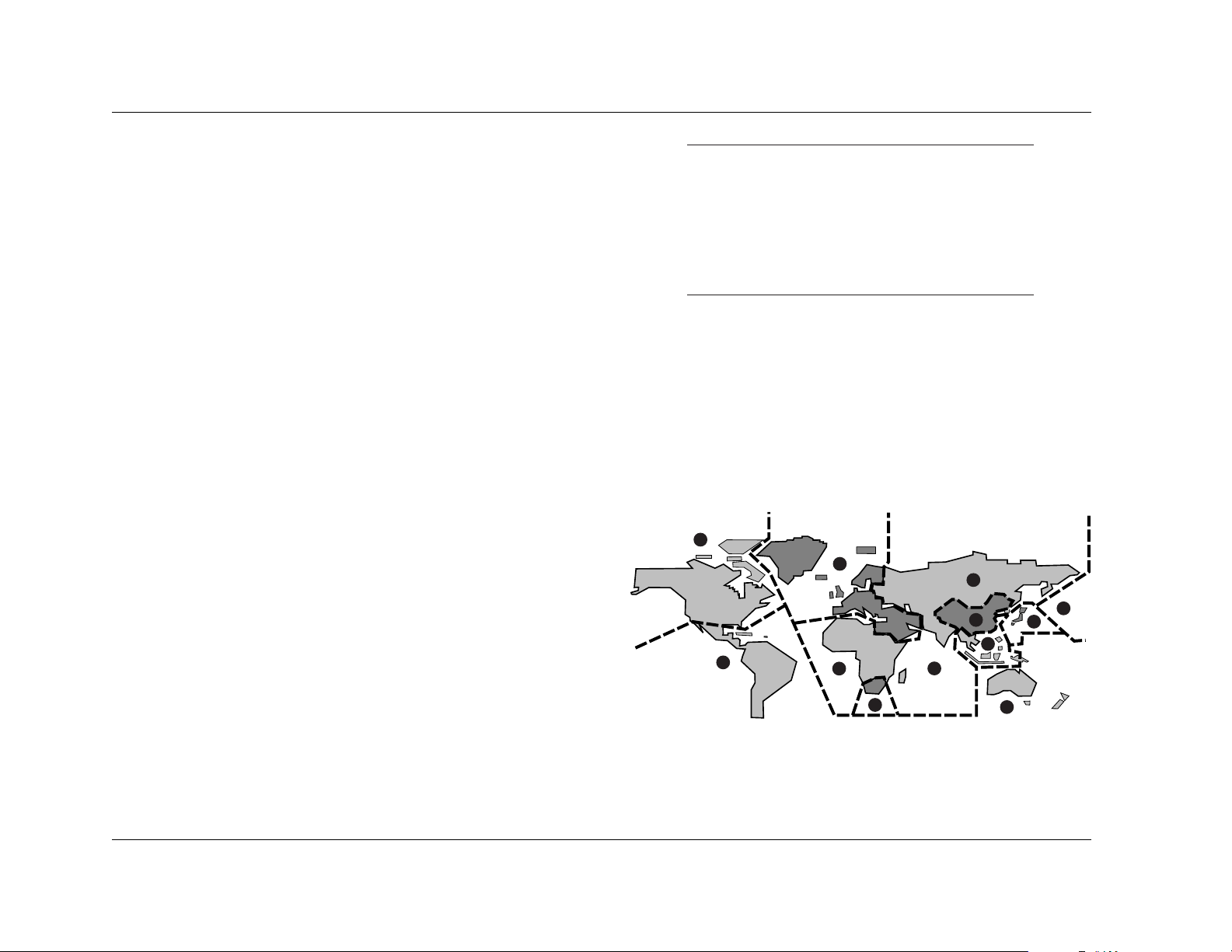
DVD-V REGIONS
The map shown below indicates DVD-V region codes for all areas
of the world. All DVD-Vs are marked with a region code, which is
often located on the disc packaging. The RT-10 rear panel is also
marked with a region code. The RT-10 is compatible with discs
marked with this same region code or with the ALL region code.
The RT-10 is not compatible with discs marked with other region
codes.
3
2
1
5
4
2
5
5
6
4
2
1
Getting Started
Lexicon
1-4
Installation Considerations (continued from page 1-3)
DO NOT . . .
• Install the RT-10 on a surface that is unstable or unable to
support all four of its feet (unless the RT-10 is installed in an
equipment rack).
• Stack the RT-10 directly above heat-producing components
such as power amplifiers and other stereo equipment that
generate heat during use. Avoid installing the RT-10 near
radiators and other heat-producing appliances.
• Expose the RT-10 to high temperatures, direct sunlight,
humidity, steam, smoke, dampness, and excessive dust.
• Install the RT-10 near unshielded TV or FM antennas, cable TV
decoders, and other RF emitting devices that might cause
interference. Replace unshielded cables with shielded cables
whenever possible.
• Prevent proper cooling. Do not block or cover ventilation slots
and openings on the RT-10 with items such as newspapers,
cloths, and curtains. Do not place the RT-10 on a thick carpet,
bed, sofa, or fabric with a thick pile.
• Expose the RT-10 to sudden or drastic temperature changes, as
this might cause condensation to form on the RT-10 lens.
Although condensation will not damage the RT-10, it might
temporarily impair performance. If this occurs, allow at least 1
hour for condensation to evaporate before attempting to load
a disc.
• Obstruct the front panel display remote control sensor when
the RT-10 is not using the IR input connector. If the RT-10 is not
using the IR IN connector, the remote control must be in lineof-sight with the front panel display remote control sensor.
Refer to page 2-14 for more information.
Page 18
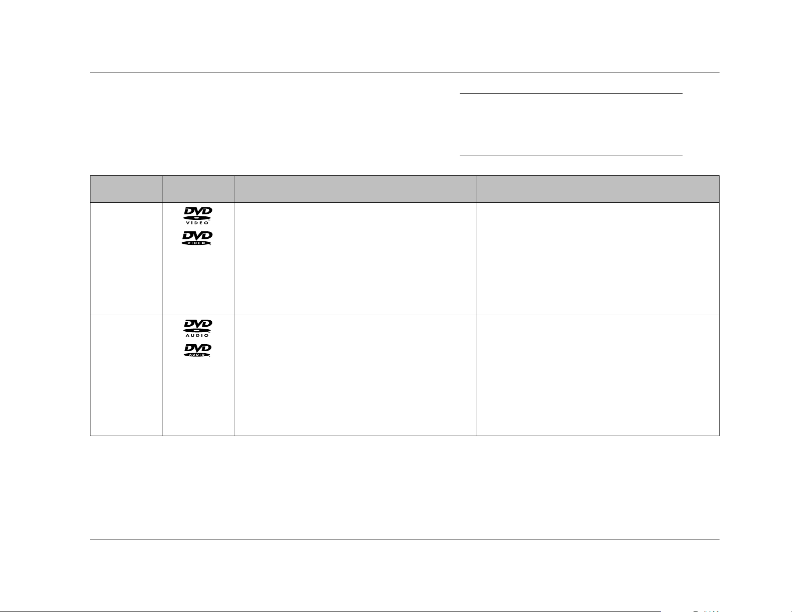
Format Logo Disc Compatibility Requirements Additional Information
Getting Started
RT-10
1-5
DVD-V
DVD-A
The RT-10 supports:
• 5-inch (12cm) or 3-inch (8cm) discs
• Dolby Digital, DTS, MPEG, or PCM (Linear) digital
audio
• MPEG-2 video
• Single- or double-sided discs
• Single- or dual-layered discs
The RT-10 supports:
• 5-inch (12cm) or 3-inch (8cm) discs
• Linear or PCM (Packed) digital audio (discs might
also include Dolby Digital, DTS, or MPEG digital
audio and MPEG-2 video)
• MPEG-2 video
• Single- or double-sided discs
• Single- or dual-layered discs
• Discs are divided into titles, which are further
divided into chapters.
• Discs are divided into groups, which are further
divided into tracks.
DISC COMPATIBILITY
The RT-10 is compatible with disc formats that meet the
requirements listed in the tables that begin below. Refer to the Disc
Care & Handling section (1-8), the Loading Discs section (4-2), and
the Disc Maintenance section (5-16) for more information.
. . . Disc Compatibility continues on page 1-6
Note:
The RT-10 is not compatible with DVD-ROM,
DVD-RAM, CD-ROM (except those that include
compatible MP3 tracks), and Photo CD formats.
Page 19
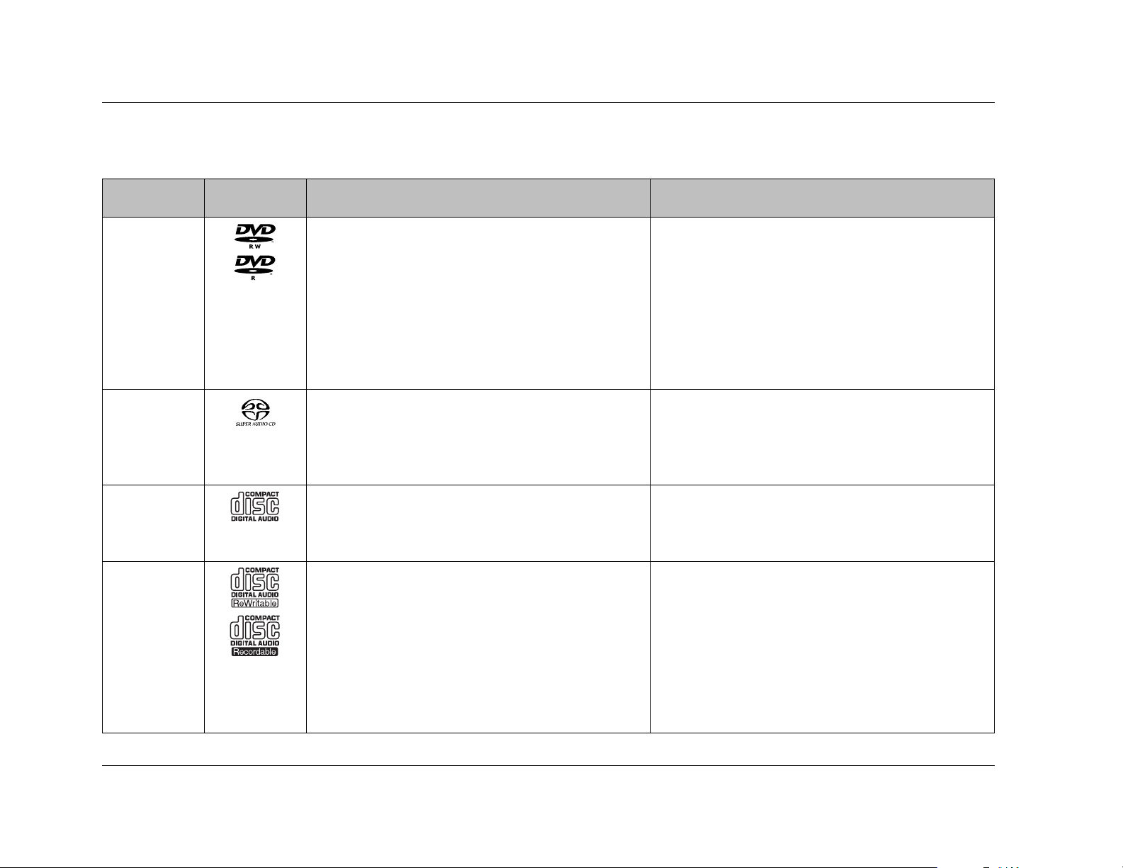
Format Logo Disc Compatibility Requirements Additional Information
Getting Started
Lexicon
1-6
Disc Compatibility (continued from page 1-5)
SACD
Audio CD
The RT-10 supports:
• 5-inch (12cm) or 3-inch (8cm) discs
• Digital audio (DSD)
• Single-, dual-, or hybrid-layered discs
The RT-10 supports:
• 5-inch (12cm) or 3-inch (8cm) discs
• PCM (Linear) digital audio
• Discs are divided into tracks.
• Discs are divided into tracks.
DVD-RW/R
The RT-10 supports:
• 5-inch (12cm) or 3-inch (8cm) discs
• Discs recorded in DVD-V format
The RT-10 does not support:
• Unfinalized discs
• Discs that include MP3 tracks
• Copy-once protected discs*
• The RT-10 might not allow playback of DVD-RW/Rs
recorded with a personal computer if incorrect
software application settings were used during
the recording process – even if the disc was
recorded in a compatible format. Refer to the
software application documentation for more
information.
CD-RW/R
The RT-10 supports:
• 5-inch (12cm) or 3-inch (8cm) discs
• Discs recorded in Video CD or Audio CD format
• Discs that include MP3 audio tracks that meet the
requirements outlined in the table on the next
page
• Discs that are unfinalized, although some time
information (i.e. playback time) will not display
• The RT-10 might not allow playback of CD-RW/Rs
recorded with a personal computer if incorrect
software application settings were used during
the recording process – even if the disc was
recorded in a compatible format. Refer to the
software application documentation for more
information.
* When a copy-once protected disc is loaded, the message "COPY PROTECT PROGRAM. UNPLAYABLE." appears on the on-screen and front panel displays.
Page 20
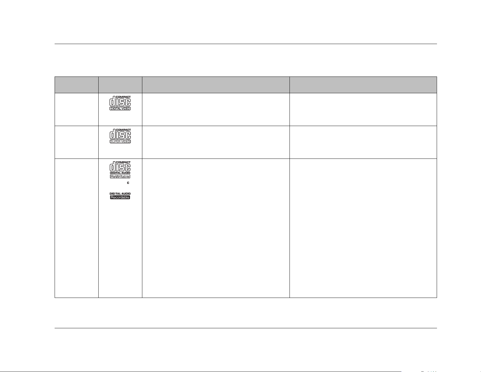
Format Logo Disc Compatibility Requirements Additional Information
Getting Started
RT-10
1-7
Video CD
SVCD
MP3
The RT-10 supports:
• 5-inch (12cm) or 3-inch (8cm) discs
• MPEG-1 digital audio and MPEG-2 video
The RT-10 supports:
• 5-inch (12cm) or 3-inch (8cm) discs
• PCM (Linear) digital audio
The RT-10 supports:
• MP3 tracks recorded on a 5-inch (12cm) or 3-inch
(8cm) CD-RW/R that is ISO 9660 compatible.
The disc can be finalized or unfinalized, although
some time information (i.e. playback time) will
not display when an unfinalized disc is loaded.
• MP3 tracks recorded in MPEG-1 Audio Layer 3
format with a 44.1 or 48kHz sample rate.
• MP3 tracks that are named with a .mp3 or .MP3
extension. The first eight characters of folder and
track names – excluding the extension – appear
on the on-screen and front panel displays.
The RT-10 does not support:
• MP3 tracks that do not meet ALL of the
requirements listed above.
• MP3 tracks recorded on DVD-RW/Rs.
• Discs are divided into tracks.
• Discs are divided into tracks.
• The RT-10 supports MP3 tracks encoded at less
than 128kBps. However, sound quality will be
impaired when playback of these tracks is in
progress.
• The RT-10 recognizes a maximum of 250 folders
per disc and 250 tracks per folder. It ignores all
folders and tracks that exceed this number.
• The RT-10 does not support multi-session discs. It
recognizes the first session recorded on the disc
and ignores all other sessions.
• The RT-10 supports some VBR (Variable Bit Rate)
tracks, although some time information (i.e.
playback time) will not display when playback of
a VBR track is in progress.
• Refer to page 4-11 for information about MP3
playback.
Page 21
• Load single-sided discs with the label side facing upward and
double-sided discs with the side intended for playback facing
downward. All loaded discs must align with the circular guide
inside the disc drawer.
• Return discs to their cases when not in use. Discs should be
stored in an upright position out of direct sunlight and
excessive heat, humidity, or cold.
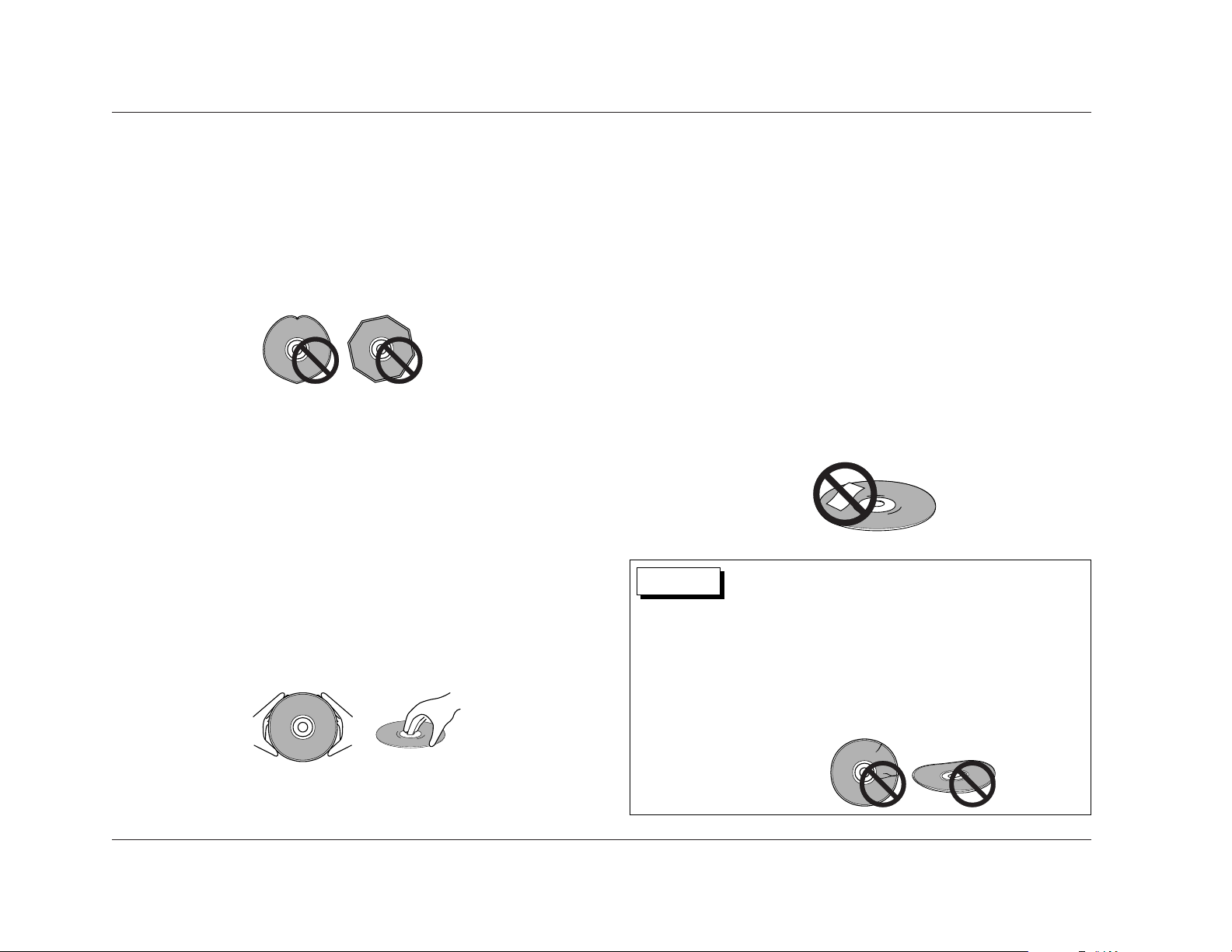
DO NOT . . .
• Write on disc labels or surfaces with ballpoint pens, pencils,
and other sharp-tipped writing instruments. Do not glue paper
or attach stickers to discs as shown below. Although not as
fragile as the recorded side, damage to the label side of the
disc can still render the disc unplayable.
Getting Started
Lexicon
1-8
Disc Compatibility (continued from page 1-7)
DISCS TO AVOID
The RT-10 is compatible with 5-inch (12cm) and 3-inch (8cm)
conventional, round discs. Do not attempt to load discs with other
size and shape characteristics, such as those shown below. All discs
must align with the circular guide inside the disc drawer.
DISC CARE & HANDLING
Discs require special care and handling to ensure optimal
performance. Pay particular attention to the bulleted items that
begin at the top of the next column and to other precautions that
appear throughout this user guide. In particular, refer to the Disc
Compatibility section (1-5), the Loading Discs section (4-2), and
the Disc Maintenance section (5-16).
DO . . .
• Hold discs at their center hole and outer edges as shown
below. Take care not to leave fingerprints, dirt, and scratches
on the disc surfaces.
The RT-10 is a single-disc player. Do not attempt to insert more
than one disc in the disc drawer at one time. This might cause
damage to the RT-10, the discs, or both.
Dirty or damaged discs such as those shown below might
affect playback performance or damage the RT-10. Do not
attempt to load cracked, chipped, scratched, warped, dirty, or
otherwise damaged discs in the disc drawer.
CAUTION
Page 22
Getting Started
RT-10
1-9
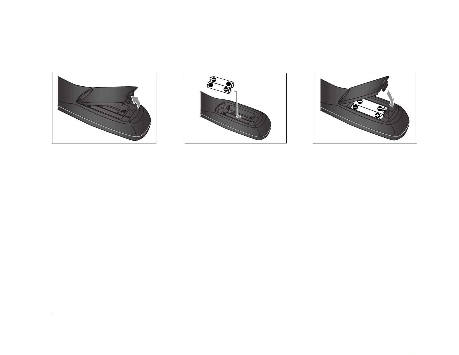
The remote control requires two AA batteries that should be
replaced as needed. It is strongly recommended to use Alkaline
batteries, which last longer without leaking.
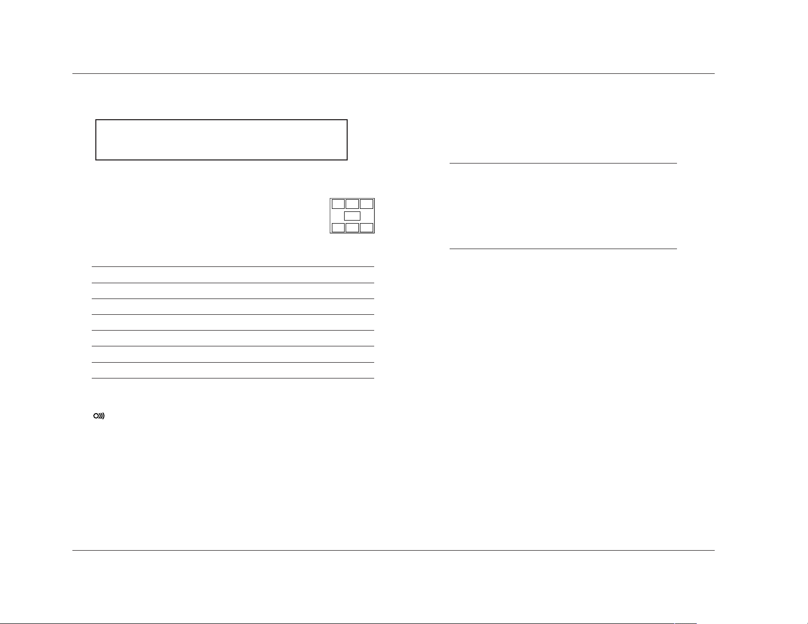
To replace the remote control batteries:
1. Locate the battery compartment on the back of the remote
control. Then, remove the battery compartment cover as
shown in Figure A (above). To do this, press the tab attached
to the cover. When the tab is pressed, pull the cover away from
the remote control.
2. Remove and dispose of old batteries inserted in the
compartment (if applicable).
3. Insert two AA batteries in the compartment as shown in Figure B
(above). Make sure the batteries are correctly inserted observing
the proper polarity.
4. When new batteries have been inserted, close the battery
compartment cover as shown in the Figure C (above). To do
this, align the cover with the guide on the back of the remote
control. Then, press the cover until it "snaps" into place.
5. It is recommended to refer to the Remote Control Overview
section that begins on page 2-14 before operating the remote
control.
REMOTE CONTROL BATTERY INSTALLATION
Figure A Figure B Figure C
Page 23

2
Basic Operation
Front Panel Overview . . . . . . . . . . . . . . . . . . . . . . . . . . . . . . . . . . . . . . 2-2
Front Panel Display Indicators
Rear Panel Overview . . . . . . . . . . . . . . . . . . . . . . . . . . . . . . . . . . . . . . . 2-8
Rear Panel Connections
Remote Control Overview . . . . . . . . . . . . . . . . . . . . . . . . . . . . . . . . . . 2-14
Operation Considerations • Command Matrix
Page 24
1
Basic Operation
Lexicon
2-2
2. Standby LED
Lights to indicate that standby mode is activated. Standby
mode can be activated and deactivated with the remote
control POWER button or with an associated component
connected to the RT-10 trigger input connector. Standby mode
is automatically activated after 30 minutes of non-use when
the AUTO_P parameter (3-52) is set to ON_30MIN.
When the RT-10 is not configured for trigger control, the
remote control POWER button can be used to activate and
deactivate standby mode. When the RT-10 is configured for
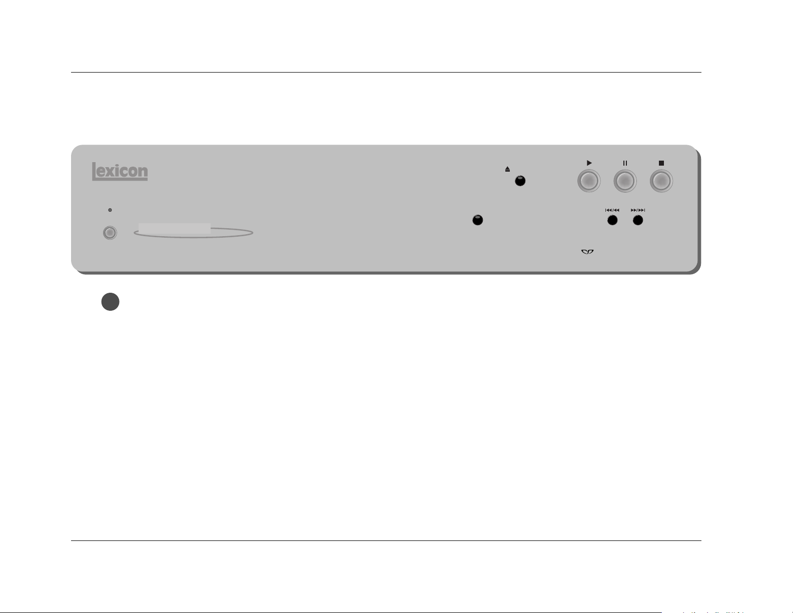
FRONT PANEL OVERVIEW
1. On/Off Button
Connects power from the AC input connector to the RT-10.
When the RT-10 is powered on, pressing the On/Off button
powers the RT-10 off and automatically deactivates standby
mode. When the RT-10 is powered off, pressing the On/Off
button powers the RT-10 on. When the RT-10 is powered on,
standby mode is deactivated, even if standby mode was
activated when the RT-10 was powered off. The On/Off button
cannot be used to activate standby mode.
On/Off
Standby
RT-10 Disc Player
Display
Off
Open/Close
Page 25
4. Front Panel Display
Provides at-a-glance viewing of status information about the
RT-10 and the loaded disc. Refer to the Front Panel Display
section that begins on page 2-6 for more information.
5. Display Off Button
Activates and deactivates the front panel display. When the
front panel display is activated, pressing the Display Off button
deactivates the front panel display and lights the Display Off
button LED. When the front panel display is deactivated, pressing
the Display Off button activates the front panel display.
The Display Off button LED:
• Lights to indicate that the front panel display is deactivated
• Does not light when the front panel display is activated
• Blinks to indicate that the Advanced Setup menu is open
on the front panel display
. . . Front Panel Overview continues on page 2-4
Basic Operation
RT-10
2-3
trigger control, the associated component connected to the
RT-10 trigger input connector can be used to activate and
deactivate standby mode.
When the RT-10 is powered off, standby mode is automatically
deactivated, although the Standby LED remains lit for a few
seconds after the RT-10 is powered off. When the RT-10 is
powered on, standby mode is also deactivated, even if
standby mode was activated when the RT-10 was powered off.
The front panel On/Off button cannot be used to activate
standby mode.
Note:
Power is still supplied to the RT-10 when standby
mode is activated.
3. Disc Drawer & Open/Close Button
Loads and unloads the inserted disc. When the disc drawer is
closed, pressing the Open/Close button opens the disc drawer.
When the disc drawer is open, pressing the Open/Close button
closes the disc drawer. The disc drawer can also be closed with
a gentle press against the front of the disc drawer.
When the disc drawer is open, pressing the Play button closes
the disc drawer and activates playback from the beginning of
the loaded disc. Whenever the disc drawer is closed, the RT-10
attempts to load a disc, even if the disc drawer is empty.
Single-sided discs should be loaded with the label side facing
upward and double-sided discs should be loaded with the side
intended for playback facing downward. All discs must align
with the circular guide inside the disc drawer. Refer to the
Loading Discs section that begins on page 4-2 for more information.
The RT-10 is a single-disc player. Do not attempt to insert
more than one disc into the disc drawer at one time. This
might cause damage to the RT-10, the discs, or both.
CAUTION
Page 26

Basic Operation
Lexicon
2-4
7. Pause Button
Activates pause mode, which pauses playback of the loaded
disc at the current playback time. When playback is activated,
pressing the Pause button activates pause mode at the current
playback time. In some cases, a still frame image appears on
the associated display device screen. When pause mode is
activated, pressing the Pause or Play button activates playback
at the current playback time. When resume or stop mode is
active, pressing the Pause button performs no function.
8. Stop Button
Activates resume mode, which pauses playback of the loaded
disc at the current playback time. The Stop button can also be
used to activate stop mode, which stops playback of the
loaded disc. The table on page 4-12 indicates the playback
modes available for each disc format.
When playback or pause mode is activated, pressing the Stop
button activates resume or stop mode. In some cases, the Stop
button must be pressed twice in succession to activate stop
mode. When resume mode is activated, pressing the Stop
button activates stop mode.
Front Panel Overview (continued from page 2-3)
The numbers in the RT-10 front panel illustration shown on page
2-2 correspond to the numbered items that continue below.
5. Display Off Button (continued)
The DISP_MODE parameter (3-52) can be used to select the
front panel display mode for SACD, CD, and MP3 playback.
When set to ON, the front panel display is deactivated during
SACD, CD, and MP3 playback. When playback mode is
activated, pressing the Display Off button activates the front
panel display for about 3 seconds. When stop mode is
activated, the front panel display remains activated until
playback resumes.
6. Play Button
Activates playback of the loaded disc at regular playback
speed. When pause or resume mode is activated, pressing the
Play or Pause button activates playback at the current playback
time. When stop mode is activated, pressing the Play button
activates playback from the beginning of the loaded disc.
When the disc drawer is open, pressing the Play button closes
the disc drawer and activates playback from the beginning of
the loaded disc.
Page 27

Basic Operation
RT-10
2-5
9. Reverse Skip/Scan Button /
Skips and scans in reverse direction through the loaded disc.
When resume or stop mode is activated, pressing the /
button activates playback from the beginning of the loaded
disc.
When playback or pause mode is activated:
• Pressing and releasing the / button skips to the
beginning of the current chapter or track. Subsequent
presses skip to the beginning of the previous chapter or
track. When the RT-10 loads the selection, playback or
pause mode reactivates from the beginning of the selected
chapter or track.
• Pressing and holding the / button scans through the
loaded disc in reverse direction. When the button is
released, playback or pause mode reactivates at the current
playback time. The front panel / button scans at one
speed. The remote control button scans at three speeds.
• When the beginning of the disc is reached, pressing the
/ button performs no function. Playback activates
from the beginning of the loaded disc, even if the /
button is pressed and held.
10.Forward Skip/Scan Button /
Skips or scans in forward direction through the loaded disc.
When resume or stop mode is activated, pressing the /
button activates playback from the beginning of the loaded
disc.
When playback or pause mode is activated:
• Pressing and releasing the / button skips to the
beginning of the next chapter or track. Subsequent presses
also skip to the beginning of the next chapter or track.
When the RT-10 loads the selection, playback or pause
mode reactivates from the beginning of the selected
chapter or track.
• Pressing and holding the / button scans through the
loaded disc in forward direction. When the button is
released, playback or pause mode reactivates at the current
playback time. The front panel / button scans at one
speed. The remote control button scans at three speeds.
• When the end of the disc is reached, pressing the /
button performs no function. Pause mode activates from
the beginning of the loaded disc, even if the / button
is pressed and held.
Page 28
Basic Operation
Lexicon
2-6
V-PART
GRP
TITLE
192kHz
96kHz
CHP
LAST
TOTAL
COND
REMAIN
5.1CH
DOWN MIX
VCD
TRKD OFF
PROGRESSIVE
DOLBY D
LFE
C
R
L
S
LS
RS
V OFF
1
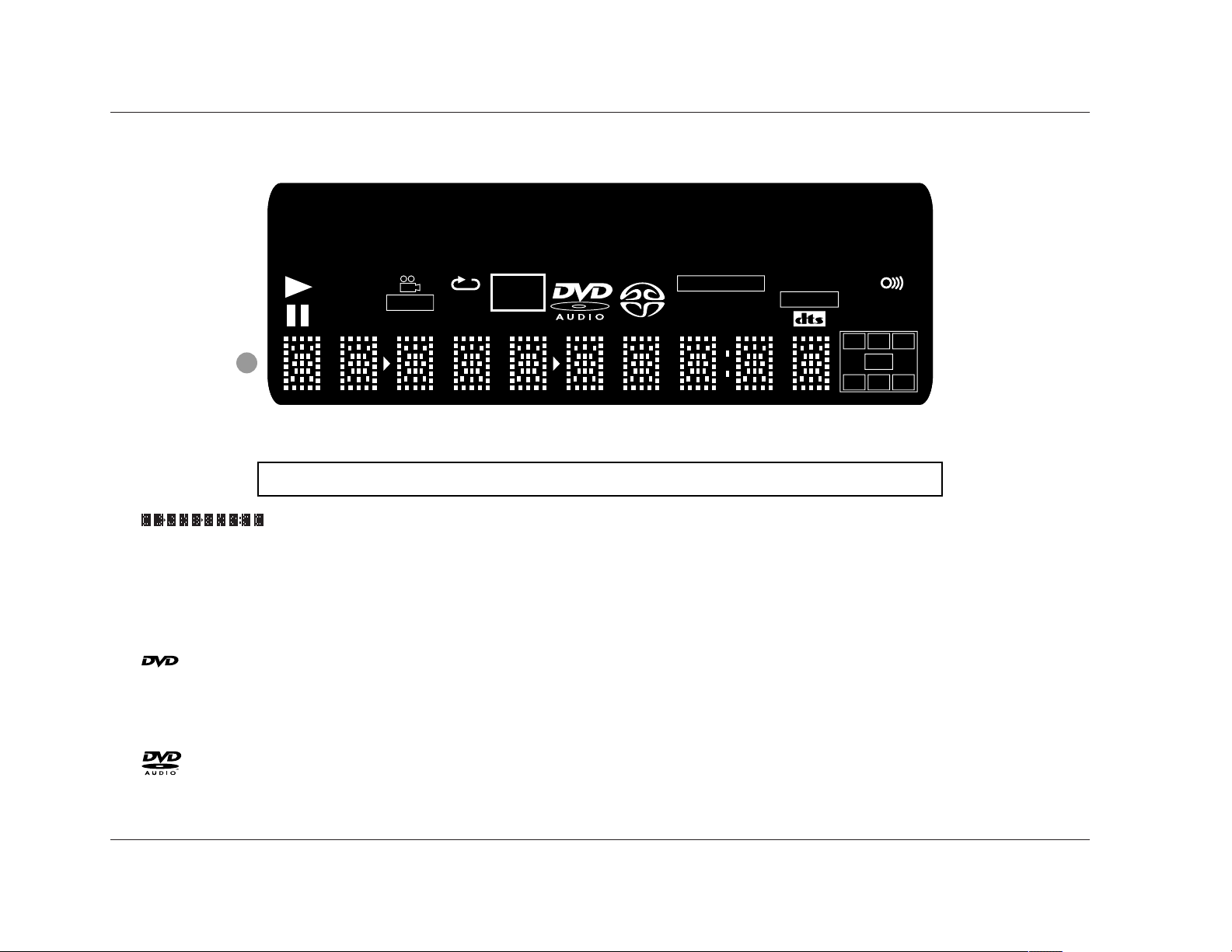
The numbers in the RT-10 front panel display illustration shown above correspond to the numbered items that begin below.
1.
(Character Display)
Provides at-a-glance viewing of status
information about the RT-10 and the
loaded disc.
2.
Indicates that a DVD-V or DVD-RW/R
is loaded.
3.
Indicates that a DVD-A is loaded.
4.
Indicates that a Video CD is loaded.
5.
Page 29

Basic Operation
RT-10
2-7
11.
Indicates that the second character
on the character display (previous
page) is a track number.
12.
Indicates that the last three characters
on the character display (number 1)
represent the remaining playback
time.
13.
Indicates that the last three characters
on the character display (previous
page) represent the total playback
time.
14.
Indicates that playback (4-11) is
activated.
15.
Indicates that pause mode (4-15) is
activated.
16.
Indicates that repeat playback (4-19)
is activated.
TOTAL
REMAIN
TRK
17.
Indicates that playback of the video
portion of the loaded disc is in
progress.
18.
Indicates that playback of a scene
recorded from multiple camera angles
is in progress. Refer to page 4-9 for
information.
19.
Indicates that last memory playback
(4-13) is activated.
20.
Indicates that preferred disc settings
have been stored for the loaded
disc. Refer to page 4-10 for more
information.
21.
Indicates that the RT-10 video output
connectors are deactivated. The
remote control VIDEO ON/OFF
button can be used to activate and
deactivate all RT-10 video output
connectors.
V OFF
COND
LAST
V-PART
22.
Indicates that the RT-10 component
video output connectors are passing
progressive-scan (non-interlaced)
video signals.
23.
Indicates that the RT-10 digital audio
output connectors are deactivated.
The Digital Out parameter (3-14) can
be used to activate and deactivate all
RT-10 digital audio output connectors.
24.
Indicates that the Audio Out parameter
(3-16) is set to 5.1 Channel.
25.
Indicates that the Audio Out parameter
(3-16) is set to 2 Channel.
26.Sample Rate Indicator
Indicates that a 192kHz or 96kHz
source is present. The sample rate –
192kHz or 96kHz – appears in red.
. . . Front Panel Display Indicators continues on page 2-8
DOWN MIX
5.1 CH
D OFF
PROGRESSIVE
Page 30
REAR PANEL OVERVIEW
The RT-10 is manufactured for sale in several different countries.
Each version features a rear panel that includes connectors and
safety instructions appropriate to that particular region.
Note:
The rear panel shown on the next page includes all
possible connectors. However, certain connectors are
not included on some versions. These instances are
noted in the rear panel connector descriptions that
begin below.
1. Region Code Indicator
Indicates the RT-10 region code, which differs from version to
version depending on the region of purchase. All DVD-Vs are
also marked with a region code, which is often located on the
disc packaging. The RT-10 is compatible with discs marked
with this same region code or with the ALL region code. The
RT-10 is not compatible with discs marked with other region
codes.
2. AC Input Connector
Provides power to the RT-10 through the supplied power cord
(2 wire, 10 amp, IEC 320). The supplied power cord features
the appropriate male-end connector for the region of
purchase.
Basic Operation
Lexicon
2-8
Front Panel Display Indicators (continued from page 2-7)
The numbers in the RT-10 front panel display illustration shown on
page 2-6 correspond to the numbered items that continue below.
27.Channels Indicator
Indicates all audio channels available on the
loaded disc. The table below provides the channel
associated with each letter abbreviation.
Channel Output Connector
L Front Left
C Center
R Front Right
LFE* Subwoofer (Low Frequency Effects)
LS Surround Left
S Subwoofer
RS Surround Right
* LFE information is sent to the Sub analog audio output connector.
28.
Indicates that the RT-10 is receiving a remote control IR
command, even when the RT-10 is using the IR IN connector.
The RT-10 does not receive remote control commands unless
the RT-10 is powered on with the front panel On/Off button.
LFE
C
R
L
S
LS
RS
Page 31

Damaged power cords can cause fire or electric shock. Please
observe the following when handling power cords:
• Handle power cords at the plug.
• Never disconnect power cords by pulling on the cord.
• Never touch power cords with wet hands, as this could
cause short circuit or electric shock.
• Protect power cords from being pinched or walked on,
particularly at plugs, convenience receptacles, and points
of connection with the unit.
• Never tie knots in power cords or tie power cords together.
• Examine power cords for damage on a regular basis.
CAUTION
Never make or break connections to the RT-10 unless the
RT-10 and all associated components are powered off.
CAUTION
Basic Operation
RT-10
2-9
3. Component Video Output Connectors
Provide component video output. All versions include one
group of RCA and one group of BNC connectors labeled
COMPONENT VIDEO. Some versions also include a Mini D
Ribbon connector labeled D1/D2. All component video output
connectors can be used at the same time.
. . . Rear Panel Overview continues on page 2-10
Apparatus Claims of U.S. Patent Nos. 4,631,603, 4,577,216,
4,819,098, and 4,907,093 licensed for limited viewing uses only.
COMPONENT VIDEO
PB
PR
Y
Page 32

Basic Operation
Lexicon
2-10
3. Component Video Output Connectors (continued)
The component video output connectors provide progressivescan and interlaced component video output. Progressive-scan
component video output converts interlaced video signals to
progressive video signals, doubling the amount of video
information sent to a compatible display device. The result is a
higher quality, more stable image with fewer video artifacts.
4. Composite Video Output Connectors
Provide composite video output. All versions include two RCA
connectors labeled VIDEO. All composite video output
connectors can be used at the same time.
5. S-video Output Connector
Provide S-video output. All versions include one S-video
connector labeled S-VIDEO.
6. Euro or Peritel (TV A/V) Connector
Provides composite, S-video, or RGB video and two channels of
audio output. Some versions include one SCART connector
labeled TV A/V CONNECTOR. The Video Out parameter (3-27)
controls video output format when the RT-10 is using the Euro
or Peritel (TV A/V) connector.
Rear Panel Overview (continued from page 2-9)
The numbers in the RT-10 rear panel illustration shown on page
2-9 correspond to the numbered items that continue below.
7. Digital Audio Output Connectors
Provide digital audio output. All versions include one coaxial
and one optical connector labeled S/PDIF, as well as one XLR
connector labeled AES/EBU. The connector labeled AES/EBU
provides S/PDIF digital audio output with AES/EBU electrical
characteristics.
8. Analog Audio Output Connectors
Provide analog audio output. All models include eight RCA
connectors labeled Front L/R (2 pairs), Surround L/R, Center,
and Sub. The Audio Out parameter (3-16) can be used to
configure these connectors to provide 2- or 5.1-channel analog
audio output.
9. Trigger Input Switch
Enables and disables trigger control when the trigger input
connector (number 10) on the RT-10 is connected to the
trigger output connector on an associated component.
When the trigger input connector on the RT-10 is connected to
the trigger output connector on an associated component and
the trigger input switch is set to ON, the RT-10 responds when
standby mode is activated or deactivated for the connected
component. Whenever the trigger input switch is set to ON,
the remote control POWER button cannot be used to
activate and deactivate standby mode, even when the RT-10
is not using the trigger input connector.
Page 33

Basic Operation
RT-10
2-11
Note:
The trigger input switch setting does not take effect
until the RT-10 is power cycled with the front panel
On/Off button.
10.Trigger Input Connector
Allows the RT-10 to be controlled with an associated
component that includes a 12V DC trigger output connector,
such as the MC-12 or MC-8 Digital Controllers. All versions
include one trigger input connector labeled TRIGGER INPUT,
which is available on a removable terminal block.
To configure the RT-10 for trigger control:
1. Connect the trigger input connector on the RT-10 to a 12V
DC trigger output connector on an associated component
component.
2. Set the RT-10 trigger input switch (previous page) to ON.
3. Power cycle the RT-10 with the front panel On/Off button
(2-2).
The RT-10 will respond when standby mode is activated or
deactivated for the connected component. The RT-10 will not
respond to the remote control POWER button.
11.IR IN Connector
Provides input of infrared data from industry-standard infrared
distribution equipment. All models include one female 3.5mm
Tip/Ring/Sleeve connector labeled IR IN.
REAR PANEL CONNECTIONS
The RT-10 is manufactured for sale in several different countries.
Each version features a rear panel that includes connectors and
safety instructions appropriate to that particular region.
Note:
The rear panel shown on page 2-9 includes all
possible connectors. However, certain connectors are
not included on some versions. These instances are
noted in the rear panel connector descriptions that
begin on page 2-8.
All versions require at least one video and one audio connection.
These are the minimum connections required for playback.
However, it is recommended to configure a digital and an analog
audio connection for optimal performance. An analog audio
output connection is required for SACD playback and
recommended for DVD-A playback. All connections require
standard video and audio cables.
Video Connections
Note:
All video output connectors are active at all times
unless deactivated with the remote control VIDEO
ON/OFF button (2-15).
. . . Video Connections continues on page 2-12
Page 34

Basic Operation
Lexicon
2-12
Video Connections (continued from page 2-11)
When a component video output connection is not possible, it is
recommended to use an S-video output connection, which
provides better picture quality than a composite video output
connection. All versions offer S-video output on an S-video output
connector.
S-video cables can be difficult to connect. Because these cable
plugs are keyed, it is important to insert them with the proper
orientation to the connector. Make sure the cable plug is properly
aligned with the connector before the cable plug is inserted. In
addition, make sure the cable plug is fully inserted for a solid
connection.
When neither a component nor S-video output connection is
possible, use a composite video output connection. All versions
offer composite video output on an RCA connector. Some versions
also offer composite video output on a Euro or Peritel (TV A/V)
connector (below).
Euro or Peritel (TV A/V) Connections
Some versions include a Euro or Peritel (TV A/V) connector that
offers composite, S-video, or RGB video and two channels of audio
output on a SCART connector labeled TV A/V CONNECTOR. When
making this connection, use a 21-pin male-to-male SCART cable
with a SCART plug on both ends. The Video Out parameter (3-27)
controls video output format when the RT-10 is using the Euro or
Peritel (TV A/V) connector. Refer to the table and illustration at the
top of the next page for more information.
Whenever possible, it is recommended to use a component video
output connection. All versions offer component video output on a
group of RCA or BNC connectors. Some versions also offer
component video output on a Mini D Ribbon connector. Refer to
the table and illustration above for more information about the
Mini D Ribbon connector.
Progressive-scan component video output is available on all
component video output connectors. Compared to interlaced
video signals, progressive-scan video signals double the amount of
video information sent to a compatible display device. For highest
picture quality, it is recommended to use a progressive-scan
compatible display device.
Note:
Progressive-scan component video output is only
available for NTSC discs
1 2 3 4 5 6 7
8 9 10 11 12 13 14
Pin Description
1 Y or Green
2 Green Ground
3 BY, B-Y, or Blue
4 Blue Ground
5 RY, R-Y, or Red
6 Red Ground
All other pins are N/C (no connection).
Mini D Ribbon Component Video Output Connector
Page 35

Basic Operation
RT-10
2-13
2468101214161820
21
135791113151719
Pin Description
1 Audio Out Right
2NC
3 Audio Out Left + Mono
4 Audio Ground
5 RGB Blue Ground
6NC
7 RGB Blue Out
8 Audio/RGB Switch/16:9
9 RGB Green Ground
10 NC
11 RGB Green Out
Euro or Peritel (TV A/V) Connector
Pin Description
12 NC
13 RGB Red Ground
14 Ground
15 RGB Red Out/Chrominance
16 RGB Switch
17 Composite Video Ground
18 Ground
19 Composite Video Out/Luminance
20 NC
21 Ground/Shield (Chassis)
connections, use an interconnect cable with Toslink® plugs on
each end. Because these cable plugs are keyed, it is important to
insert them with the proper orientation to the connector. Make
sure the cable plug is properly aligned with the connector before
the cable plug is inserted. When the cable plug is inserted, the
protective shutter on the connector will open and the plug will
click into position, indicating that the cable plug is fully inserted.
Analog Audio Connections
All versions offer analog audio output on eight RCA connectors
labeled Front L/R (2 pairs), Surround L/R, Center, and Sub. When
making these connections, use standard audio cables with RCA
plugs on each end. The Audio Out parameter (3-16) can be used
to configure these connectors to provide 2- or 5.1-channel analog
audio output.
The analog audio output connectors are color-coded to match the
cable plugs. Make sure the cable plugs are fully inserted for a solid
connection.
DVD-A & SACD Connections
An analog audio output connection is required for SACD and
recommended for DVD-A playback. When DVD-A sources are sent
to the digital audio output connectors, multi-channel signals are
downmixed and high sample rates of 176.4 or 192kHz are
downsampled to 44.1, 48, 88.2, or 96kHz. The downsampled rate
differs from disc to disc.
Digital Audio Connections
All versions offer digital audio output on S/PDIF coaxial, S/PDIF
optical, and XLR (AES/EBU) connectors. The AES/EBU connector
offers S/PDIF digital audio output with AES/EBU electrical
characteristics.
When making S/PDIF coaxial connections, use a video interconnect
cable with RCA plugs on each end. Make sure the cable plug is fully
inserted for a solid connection. When making S/PDIF optical
Page 36

Basic Operation
Lexicon
2-14
REMOTE CONTROL OVERVIEW
The RT-10 remote control provides full operation of the RT-10,
executing functions such as menu navigation that are not available
from the front panel. The numbers in the RT-10 remote control
illustrations shown on pages 2-15 to 2-18 correspond to the
numbered items in the Command Matrix that begins on page 2-15.
The Command Matrix describes the commands remote control
buttons execute.
OPERATION CONSIDERATIONS
The bulleted items that begin below describe factors that can
improve or impede remote control operation. It is recommended
to observe these items as well as the battery installation instructions
on page 1-9 before operating the remote control.
Note the following:
• If the RT-10 is not using the IR IN connector, the remote
control must be in line-of-sight with the front panel display
remote control sensor. Eliminate obstructions between the
remote control and the remote control sensor. The remote
control might become unreliable if strong sunlight or
fluorescent light is shining on the remote control sensor.
• For optimal performance, position the remote control at a 30
degree angle no more than 17 feet (5m) from the RT-10 as
shown below. If the RT-10 is placed inside a glass cabinet,
smoked glass will reduce the remote control range.
• Remote controllers for different components can interfere with
one another. It is recommended to avoid using remote controls
for different components at the same time.
• The remote control requires two AA batteries that should be
replaced as needed. It is strongly recommended to use Alkaline
batteries, which last longer without leaking. Refer to page 1-9
for more information.
COMMAND MATRIX
The matrix that begins on the next page describes the commands
remote control buttons execute. The numbers in the RT-10 remote
control illustration shown on the next page correspond to the
numbered items in the Command Matrix.
30
30
17 feet (5m)
Page 37

Basic Operation
RT-10
2-15
Button Command
1
POWER
Activates and deactivates standby mode when all of the following conditions are met:
• The RT-10 is not configured for trigger control.
• The RT-10 is powered on with the front panel On/Off button.
• The trigger input switch is set to OFF.
When standby mode is deactivated, pressing the POWER button activates standby mode and lights the
front panel Standby LED (2-2). When standby mode is activated, pressing the POWER button
deactivates standby mode. The Standby LED is not lit when standby mode is deactivated.
Note the following:
• Power is still supplied to the RT-10 when standby mode is activated.
2
DIMMER
Controls the brightness of front panel display characters. Pressing this button cycles through 100%,
75%, and off settings. When off is selected, the front panel Display Off button LED lights.
3
VIDEO
ON/OFF
Activates and deactivates the rear panel video output connectors, including component, composite,
S-video, and Euro or Peritel (TV A/V) connectors (2-9 and 2-10). When these connectors are deactivated,
pressing the VIDEO ON/OFF button activates these connectors, allowing video signals to pass to the
associated component. When these connectors are activated, pressing the VIDEO ON/OFF button
deactivates these connectors, preventing video signals from passing to the associated
component. The V OFF indicator (2-7) appears on the front panel display to indicate that the video
output connectors are deactivated.
4
OPEN/
CLOSE
Opens and closes the disc drawer (2-3). When the disc drawer is closed, pressing the Open/Close
button opens the disc drawer. When the disc drawer is open, pressing the Open/Close button closes
the disc drawer. The disc drawer can also be closed with a gentle press against the front of the disc
drawer.
When a disc is loaded and the disc menu is closed, pressing a number button activates playback at the
selected title, chapter, group, or track number. When a disc is loaded and the disc menu is open,
pressing a number button selects the corresponding menu item (4-5 and 4-6). In some cases, the
number buttons can also be used to enter playback mode values (Section 4).
To enter values 10 and above, press the +10 button once for numbers in the teens, twice for numbers
in the twenties, and so on. Then, press a number button (0 to 9) to enter the second digit. For instance,
entering a value of 25 requires a button sequence of +10, +10, and 5.
5
CLEAR
Deletes entries when search modes and certain playback modes are activated. Refer to Section 4 for
more information.
6
3
21
6
54
+10
9
87
0
OPEN/
CLOSE
3
21
VIDEO
ON/OFF DIMMER POWER
CLEAR
6
54
+10
9
87
0
RETURN
PROGRAM SEARCH TOP MENU
SETUP MENU
ENTER
STOP
PLAY
PREV
NEXT
RANDOM
F.MEMO VIDEO ADJ. A-B REPEAT
DISPLAY ANGLE SUBTITLE AUDIO
LAST MEMO
CONDITION
MEMO
3 2
1
5
4
6
Page 38

CommandButton
Basic Operation
Lexicon
2-16
7
SETUP
Opens and closes the Setup (3-9) and Advanced Setup (3-51) menus.
8
RETURN
Closes certain Setup menu screens without saving changes. Refer to Section 3 for more information.
9
PROGRAM
Activates program mode (4-22), which creates a program list for the loaded disc. When a program list
has been created, program mode also activates program playback.
10
SEARCH
Activates search mode (4-28), which activates playback of a specific title, chapter, group, track, folder,
time, frame, or page on the loaded disc.
11
TOP MENU
Open the disc menu or top menu, provided the loaded disc includes a menu. In some cases, pressing
the MENU and TOP MENU buttons opens the same menu. In some cases, a specific button must be
pressed to open the menu. For instance, the TOP MENU button must be pressed to open DVD-A top
menus. Refer to the Disc Menu Command Matrix on pages 4-5 and 4-6 for more information.
When the Setup or Advanced Setup menu is open, pressing the ENTER button selects the highlighted
parameter or setting. When certain playback modes are activated, pressing the ENTER button executes
the selected option. Refer to Sections 3 and 4 for more information.
Navigate through the Setup and Advanced Setup menus, as well as certain disc menus. Instances in
which the and arrows perform different functions are noted throughout this user guide. Refer to
Sections 3 and 4 for more information.
Activates playback of the loaded disc at regular playback speed. When pause or resume mode is
activated, pressing the Play or Pause button activates playback at the current playback time. When stop
mode is activated, pressing the Play button activates playback from the beginning of the loaded disc.
When the disc drawer is open, pressing the Play button closes the disc drawer and activates playback
from the beginning of the loaded disc.
MENU
12
ENTER
13
14
PLAY
15
STOP
Activates resume mode, which pauses playback of the loaded disc at the current playback time. The Stop
button can also be used to activate stop mode, which stops playback of the loaded disc. The table on
page 4-12 indicates the playback modes available for each disc format. When playback or pause mode
is activated, pressing the Stop button activates resume or stop mode. In some cases, the Stop button
must be pressed twice in succession to activate stop mode. When resume mode is activated, pressing the
Stop button activates stop mode.
OPEN/
CLOSE
3
21
VIDEO
ON/OFF DIMMER POWER
CLEAR
6
54
+10
9
87
0
RETURN
PROGRAM SEARCH TOP MENU
SETUP MENU
ENTER
STOP
PLAY
PREV
NEXT
RANDOM
F.MEMO VIDEO ADJ. A-B REPEAT
DISPLAY ANGLE SUBTITLE AUDIO
LAST MEMO
CONDITION
MEMO
11
10
11
13
14
8
9
7
12
13
15
Page 39

OPEN/
CLOSE
3
21
VIDEO
ON/OFF DIMMER POWER
CLEAR
6
54
+10
9
87
0
RETURN
PROGRAM SEARCH TOP MENU
SETUP MENU
ENTER
STOP
PLAY
PREV
NEXT
RANDOM
F.MEMO VIDEO ADJ. A-B REPEAT
DISPLAY ANGLE SUBTITLE AUDIO
LAST MEMO
CONDITION
MEMO
Basic Operation
RT-10
2-17
Button Command
16
PREV
Skips to the beginning of the current chapter or track. Subsequent presses skip to the beginning of the
previous chapter or track. When the RT-10 loads the selection, playback or pause mode reactivates from
the beginning of the selected chapter or track.
NEXT
Skips to the beginning of the next chapter or track. Subsequent presses also skip to the beginning of
the next chapter or track. When the RT-10 loads the selection, playback or pause mode reactivates from
the beginning of the selected chapter or track.
17
• When playback is activated, pressing the button scans through the loaded disc in reverse direction.
Subsequent presses cycle through available scanning speeds. The button scans at three speeds.
The front panel / button scans at one speed. Pressing the Play button reactivates
playback at the current playback time.
• When pause mode is activated, pressing and releasing the button activates frame-by-frame
playback in reverse direction. When the button is released, pause mode reactivates at the current
playback time.
• When pause mode is activated, pressing and holding the button for 1 second activates slow
playback in reverse direction at 1/16 regular playback speed. When slow playback is activated,
pressing and releasing the button cycles through 1/16, 1/8, 1/4, and 1/2 regular playback speeds.
Pressing the Play button reactivates playback at the current playback time.
• When the beginning of the disc is reached, pressing the button performs no function. Playback
activates from the beginning of the loaded disc, even if the button is pressed and held.
• When playback (4-12) is activated, pressing the button scans through the loaded disc in forward
direction. Subsequent presses cycle through available scanning speeds. The button scans at three
speeds. The front panel / button scans at one speed. Pressing the Play button reactivates
playback at the current playback time.
• When pause mode is activated, pressing and releasing the button activates frame-by-frame
playback in forward direction. When the button is released, pause mode reactivates at the current
playback time.
• When pause mode is activated, pressing and holding the button for 1 second activates slow
playback in forward direction at 1/16 regular playback speed. When slow playback is activated,
pressing and releasing the button cycles through 1/16, 1/8, 1/4, and 1/2 regular playback speeds.
Pressing the Play button reactivates playback at the current playback time.
• When the end of the disc is reached, pressing the button performs no function. Pause mode
activates from the beginning of the loaded disc, even if the button is pressed and held.
16
17
Page 40

OPEN/
CLOSE
3
21
VIDEO
ON/OFF DIMMER POWER
CLEAR
6
54
+10
9
87
0
RETURN
PROGRAM SEARCH TOP MENU
SETUP MENU
ENTER
STOP
PLAY
PREV
NEXT
RANDOM
F.MEMO VIDEO ADJ. A-B REPEAT
DISPLAY ANGLE SUBTITLE AUDIO
LAST MEMO
CONDITION
MEMO
Basic Operation
Lexicon
2-18
Button Command
Activates pause mode, which pauses playback of the loaded disc at the current playback time. When
playback is activated, pressing the Pause button activates pause mode at the current playback time. In
some cases, a still frame image appears on the associated display device screen. When pause mode is
activated, pressing the Pause or Play button activates playback at the current playback time. When
resume or stop mode is active, pressing the Pause button performs no function.
18
Activates random playback (4-17), which plays the loaded disc in a random order of titles, chapters,
groups, or tracks.
19
RANDOM
Activates repeat playback (4-19), which repeats playback of the loaded disc or the currently playing title,
chapter, group, track, folder, or program list.
20
REPEAT
Activates A-B repeat playback (4-21), which repeats playback from a user-defined start time (point A) to
a user-defined end time (point B).
21
A-B
Opens and closes the Video Adjust bar, which can be used to make exact, detailed adjustments of video
settings. Refer to the Video Adjust section that begins on page 3-29 for more information.
22
VIDEO ADJ.
Opens the Audio bar, which can be used to select the desired audio track (audio language and output
format) on the loaded disc (4-7).
23
AUDIO
Opens the Subtitle bar, which can be used to select the desired subtitle language (4-8).
24
SUBTITLE
Opens the Angle bar, which can be used to select the desired camera angle (4-9).
25
ANGLE
Activates display mode (4-30), which opens an on-screen display screen or bar that provides
information about the loaded disc
26
DISPLAY
Creates up to five shortcuts for frequently adjusted Setup menu parameters (3-50).
27
F.MEMO
Activates last memory playback (4-13), which creates a bookmark at the current playback time. Later,
playback can be reactivated from the bookmarked playback time.
Page 41

3
Setup Menus
Control Bar. . . . . . . . . . . . . . . . . . . . . . . . . . . . . . . . . . . . . . . . . . . . . . 3-2
Setup Navigator . . . . . . . . . . . . . . . . . . . . . . . . . . . . . . . . . . . . . . . . . . 3-2
Setup Menu . . . . . . . . . . . . . . . . . . . . . . . . . . . . . . . . . . . . . . . . . . . . . 3-9
Audio1 • Audio2 • Video1 • Video2 • Language • General
Setup Menu Shortcuts. . . . . . . . . . . . . . . . . . . . . . . . . . . . . . . . . . . . . 3-50
Advanced Setup Menu . . . . . . . . . . . . . . . . . . . . . . . . . . . . . . . . . . . . 3-51
Page 42

Setup Menus
Lexicon
3-2
Note:
The Setup menu should be used to configure the
RT-10 before attempting disc playback.
CONTROL BAR
When a Setup menu screen is open, a control bar similar to the one
shown below appears at the bottom of the on-screen display to
indicate which remote control buttons are available for the open
screen. These buttons appear on the control bar with a one-word
description of their associated commands.
For instance, the control bar shown below indicates that the SETUP
button, ENTER button, and and arrows are available for the
open screen. The SETUP button can be used to "Exit" or close the
open screen. The ENTER button can be used to "Select" the
highlighted setting. And, the and arrows can be used to
"Move" or navigate around the screen.
No matter which menu screen is open, the , , , and
arrows will appear on the control bar. However, only the lightercolored arrows can be used to navigate around the screen.
Move Select Exit
ENTER SETUP
SETUP NAVIGATOR
The Setup Navigator is a convenient tool that can be used to
configure basic RT-10 settings without navigating through the
entire Setup menu. It presents a series of prompts that provide
step-by-step guidance through the process of selecting minimum
audio, video, and language settings.
With the exception of the last Setup Navigator prompt, all prompts
represent a simplified version of actual Setup menu parameters. For
instance, the TV Type prompt (3-5) is associated with the Video1
tab TV Screen parameter (3-25). The table on the next page lists
all Setup Navigator prompts, along with their possible settings
and associated Setup menu parameters.
When the RT-10 is first powered on, the Setup Navigator opens on
the on-screen display whenever the remote control SETUP button
is pressed while the RT-10 is in stop mode. Otherwise, the Setup
Navigator can be opened from the Setup menu General tab (3-42).
Refer to the Setup Navigator prompt description on page 3-4 for
more information.
To open the Setup Navigator:
1. Press the Stop button to activate stop mode. In some cases,
the Stop button must be pressed twice in succession to
activate stop mode.
2. When stop mode is activated, press the remote control SETUP
button to open the Setup Navigator. If the Setup Navigator
does not open, it must be opened from the Setup menu
General tab (3-42).
Page 43

Setup Navigator
Prompt
Available Settings
Associated Setup
Menu Parameter(s)
Setup Menus
RT-10
3-3
Setup Navigator
OSD Language
TV Type
Analog Jacks
Center Speaker
• Start • Auto Start Off
• Widescreen (16:9) • Standard (4:3)
• Present `
• Not Present
• 2 Channel
• 5.1 Channel `
• Not Connected
•No
• Yes `
• Don’t Know
• Save Changes
• Delete Changes
• Start Again
• English
• français
• Deutsch
• Italiano
• Español
• Dolby Digital
• Dolby Digital/
DTS `
• Dolby Digital/
MPEG
• Dolby D/DTS/
MPEG
• PCM
• Not Connected
Setup Navigator
(General tab, 3-42)
OSD Language
(Language tab, 3-36)
TV Screen
(Video1 tab, 3-25)
Audio Out
(Audio2 tab, 3-16)
Speaker Setting
(Audio2 tab, 3-18)
Surround Speakers
• Present `
• Not Present Speaker Setting
(Audio2 tab, 3-18)
Sub-woofer
• Present `
• Not Present Speaker Setting
(Audio2 tab, 3-18)
Linear PCM Out
(Audio1 tab, 3-13)
None
Dolby Digital Out (3-12)
DTS Out (3-13)
MPEG Out (3-14)
(Audio1 tab)
Digital Jack
96kHz PCM Audio
Exit Setup Navigator
Setup Navigator Prompts
The table shown at the right lists
all Setup Navigator prompts,
along with their possible settings
and associated Setup menu
parameters.
Note:
Setup Navigator prompts should
be configured while the disc
drawer is empty.
` This setting is recommended
when the RT-10 is connected to
an MC-12 or MC-8 Digital
Controller. When no setting is
indicated, any setting can be
selected.
. . . Setup Navigator continues on page 3-4
Page 44

Setup Menus
Lexicon
3-4
1
2
3
4
5
Setup using the Setup Navigator
7
Setup Navigator
Start
Auto Start Off
Audio1 Language GeneralVideo1A2 V2
Move Select Exit
Setup Navigator
Start
ENTER SETUP
!
1
2
Language
4
5
Select the On Screen Language
7
Setup Navigator
English
francais
Deutsch
Italiano
Espanol
Audio1 Language GeneralVideo1A2 V2
Move Select Exit
OSD Language
English
ENTER SETUP
!
To navigate the Setup Navigator:
Button Command
ENTER Selects the highlighted setting. When a setting
is selected, the Setup Navigator automatically
proceeds to the next prompt.
Returns to the previous Setup Navigator
prompt. When the first Setup Navigator
prompt is open, pressing the arrow
performs no function.
and Scroll upward and downward through
parameter settings.
RETURN Closes the Setup Navigator without saving the
selected settings.
SETUP Closes the Setup Navigator and the Setup
menu without saving the selected settings.
Setup Navigator (continued from page 3-3)
Setup Navigator Start, Auto Start Off
Activates and deactivates the Setup Navigator. Select Start to
activate the Setup Navigator and proceed to the OSD Language
prompt (below). Select Auto Start Off to deactivate the Setup
Navigator. Once deactivated, the Setup Navigator must be opened
from the Setup menu General tab (3-42).
The Setup Navigator prompt is associated with the General tab
Setup Navigator parameter (3-42). When the Setup Navigator is
opened from the General tab, the Auto Start Off option is not
available.
OSD Language English, français, Deutsch, Italiano, Español
Determines the language in which RT-10 on-screen display menus
appear. The OSD Language prompt is associated with the
Language tab OSD Language parameter (3-36).
Page 45

Setup Menus
RT-10
3-5
TV Type Widescreen (16:9), Standard (4:3)
Controls the appearance of the picture on the associated display
device screen, formatting the aspect ratio of the video output
format to match the aspect ratio of the display device. Aspect
ratios, which refer to width relative to height, differ among video
output formats and display devices. A 16:9 aspect ratio is almost
twice as wide as high and a 4:3 aspect ratio is almost square.
Select Widescreen (16:9) if the associated display device screen has
a 16:9 aspect ratio. Select Standard (4:3) if the associated display
device screen has a 4:3 aspect ratio. The appearance of the picture
depends on the TV Type prompt setting, the video output format,
the loaded disc, and display device settings.
The TV Type prompt is associated with the Video1 tab TV Screen
parameter (3-25). The TV Type prompt Widescreen (16:9) setting
is equivalent to the TV Screen parameter 16:9 (Wide) setting, and
the TV Type prompt Standard (4:3) setting is equivalent to the TV
Screen parameter 4:3 (Letter Box) setting. The TV Screen parameter
also offers settings for 16:9 (Compressed) and 4:3 (Pan&Scan)
viewing. Refer to the table on pages 3-25 and 3-26 for more
information.
1
2
TV Connection
4
5
Widescreen TV
16:9 aspect ratio
Setup Navigator
Widescreen (16:9)
Standard
Audio1 Language GeneralVideo1A2 V2
Move Select Exit
TV Type
Widescreen (16:9)
ENTER SETUP
!
Note:
• Some discs do not allow video output format
adjustments.
• Neither the TV Type prompt nor the TV Screen
parameter can be adjusted when the RT-10 is in
playback mode.
Analog Jacks 2 Channel, 5.1 Channel, Not Connected
Controls analog audio output format when the RT-10 is using the
analog audio output connectors. Select Not Connected if the RT-10
is not using the analog audio output connectors.
When 2 Channel is selected, the RT-10 passes analog audio sources
to the Front L/R analog audio output connectors. When 5.1
Channel is selected, the RT-10 passes analog audio sources to the
Front L/R, Surround L/R, Center, and Sub analog audio output
connectors. Refer to the table on page 3-17 for more information.
. . . Setup Navigator continues on page 3-6
1
2
Amp Connection
4
5
2 channel jacks for L/R
7
Setup Navigator
2 Channel
5.1 Channel
Not Connected
Audio1 Language GeneralVideo1A2 V2
Move Select Exit
Analog Jacks
2 Channel
ENTER SETUP
!
Page 46

Setup Menus
Lexicon
3-6
Center Speaker Present, Not Present
Indicates the presence or absence of a center speaker. When
Present is selected, the RT-10 passes center channel signals to the
Center analog audio output connector. When Not Present is
selected, the RT-10 redirects center channel signals to the Front L/R
analog audio output connectors.
The Center Speaker prompt is associated with the Audio2 tab
Speaker Setting option, which can be used to set speaker sizes and
distances.
Surround Speakers Present, Not Present
Indicates the presence or absence of surround speakers. When
Present is selected, the RT-10 passes surround channel signals to
the Surround L/R analog audio output connectors. When Not
Present is selected, the RT-10 redirects surround channel signals to
the Front L/R analog audio output connectors.
The Surround Speakers prompt is associated with the Audio2 tab
Speaker Setting option, which can be used to set speaker sizes and
distances.
Analog Jacks (continued)
The Analog Jacks prompt is associated with the Audio2 tab Audio
Out parameter (3-16). The Analog Jacks prompt and Audio Out
parameter settings have no effect when the RT-10 is not using the
analog audio output connectors.
Note the following:
• The Analog Jacks prompt and Audio Out parameter can be
used to select the desired audio output format as long as a
compatible audio track is selected on the loaded disc. Refer to
page 4-7 for information about audio track selection.
• When the Analog Jacks prompt is set to 2 Channel, the Setup
Navigator proceeds to the Digital Jack prompt (next page).
When set to 5.1 Channel, the Setup Navigator proceeds to the
Center Speaker prompt (next column).
1
2
Amp Connection
4
5
Center speaker is connected
to an amplifier
Setup Navigator
Present
Not Present
Audio1 Language GeneralVideo1A2 V2
Move Select Exit
Center Speaker
Present
ENTER SETUP
!
1
2
Amp Connection
4
5
Surround speakers are connected
to an amplifier
Setup Navigator
Present
Not Present
Audio1 Language GeneralVideo1A2 V2
Move Select Exit
Surround Speakers
Present
ENTER SETUP
!
Setup Navigator (continued from page 3-5)
Page 47

1
2
Amp Connection
4
5
Sub-woofer is connected
to an amplifier
Setup Navigator
Present
Not Present
Audio1 Language GeneralVideo1A2 V2
Move Select Exit
Sub-woofer
Present
ENTER SETUP
!
Setup Menus
RT-10
3-7
Sub-woofer Present, Not Present
Indicates the presence or absence of a subwoofer. When Present is
selected, the RT-10 passes subwoofer signals (LFE) to the Sub
analog audio output connector. When Not Present is selected, the
RT-10 does not redirect low-frequency signals to other analog
audio output connectors.
The Sub-woofer prompt is associated with the Audio2 tab Speaker
Setting option, which can be used to set speaker sizes and
distances.
Digital Jack Refer to the table on page 3-3
Controls digital audio output format when the RT-10 is using the
digital audio output connector. Select Not Connected if the RT-10
is not using the digital audio output connector.
Select the setting that includes all digital audio sources with which
the associated component is compatible. The RT-10 will convert all
other digital audio signals to PCM signals before passing them to
the associated component. With the exception of the Not
Connected setting, all Digital Jack prompt settings assume the
associated component is compatible with PCM signals.
For example, the MC-12 and MC-8 Digital Controllers are
compatible with Dolby Digital, DTS, and PCM digital audio
sources. If the RT-10 is connected to one of these components,
select the Dolby Digital/DTS setting. The RT-10 will pass Dolby
Digital, DTS, and PCM signals directly to the MC-12 or MC-8. The
RT-10 will convert all other digital audio signals (i.e. MPEG) to PCM
before passing them to the MC-12 or MC-8.
Associated components that are NOT compatible with DTS
sources will output DTS noise when all of the following
conditions are met:
• A DTS source is present.
• The Digital Jack prompt is set to Dolby Digital/DTS or Dolby
D/DTS/MPEG OR the DTS Out parameter is set to DTS.
. . . Setup Navigator continues on page 3-8
1
2
Amp Connection
4
5
6
Compatible with Dolby Digital
Setup Navigator
Dolby Digital
Dolby Digital/DTS
Dolby Digital/MPEG
Dolby D/DTS/MPEG
PCM
Not Connected
Audio1 Language GeneralVideo1A2 V2
Move Select Exit
Digital Jack
Dolby Digital
ENTER SETUP
!
Page 48

Setup Menus
Lexicon
3-8
Select No if the associated component is not compatible with
96kHz PCM sources. The RT-10 will downsample 96kHz PCM
signals to 48kHz before passing them to the associated component.
Select Yes if the associated component is compatible with 96kHz
PCM sources. The RT-10 will not downsample 96kHz PCM signals
before passing them to the associated component. Selecting the
96kHz PCM Audio Don’t Know setting has the same effect as
selecting the No setting.
The 96kHz PCM Audio prompt is associated with the Audio1 tab
Linear PCM Out parameter, which can be set for compatibility with
PCM digital audio sources.
Note:
The RT-10 always downsamples 192 and 176kHz
signals to 96 and 88.2kHz before passing them to
the associated component, regardless of the 96kHz
PCM Audio prompt and Linear PCM Out parameter
settings.
Digital Jack (continued)
The Digital Jack prompt is associated with the Audio1 tab Dolby
Digital Out (3-12), DTS Out (3-13), and MPEG Out (3-14)
parameters. Each parameter can be independently set for
compatibility with the respective digital audio source. The Digital
Jack prompt Dolby Digital Out, DTS Out, and MPEG Out parameter
settings have no effect when the RT-10 is not using the digital
audio output connector.
Note:
When the Digital Jack prompt is set to Not
Connected, the Setup Navigator proceeds to the Exit
Setup Navigator prompt (3-4). When set to another
setting, the Setup Navigator proceeds to the 96kHz
PCM Audio prompt (below).
96kHz PCM Audio No, Yes, Don’t Know
Controls PCM digital audio output sample rate when the RT-10 is
using the digital audio output connector. This prompt is not
available when the Digital Jack prompt is set to Not Connected.
1
2
3
4
5
Changes are saved
7
Setup Navigator
Save Changes
Delete Changes
Start Again
Audio1 Language GeneralVideo1A2 V2
Move Select Exit
Exit Setup Navigator
Save Changes
ENTER SETUP
!
1
2
Amp Connection
4
5
Digital jacks not compatible with 96kHz
7
Setup Navigator
No
Yes
Don’t Know
Audio1 Language GeneralVideo1A2 V2
Move Select Exit
96kHz PCM Audio
No
ENTER SETUP
!
Setup Navigator (continued from page 3-5)
Page 49

Setup Menus
RT-10
3-9
Exit Setup Navigator Save or Delete Changes, Start Again
Determines whether Setup Navigator prompt settings are saved,
deleted, or reentered. Select Save Changes to save prompt settings
and close the Setup Navigator. Select Delete Changes to delete
prompt settings and close the Setup Navigator. Select Start Again
to reenter prompt settings. The OSD Language prompt (3-4) will
open on the on-screen display. The Exit Setup Navigator prompt is
not associated with a Setup menu parameter.
SETUP MENU
The Setup menu can be used to configure audio, video, language,
and other general RT-10 settings. Available in expert and basic
display modes, the Setup menu can be configured for the desired
level of control. The Setup Menu Mode parameter (3-42) can be
used to select the mode in which the Setup menu is displayed.
Setup Menu Mode Expert, Basic
Determines the mode in which the Setup menu is displayed. Select
Expert to display the Setup menu in expert mode, which includes
all available parameters. The Setup menu is shown in expert mode
at the top of the next page. Select Basic to display the Setup menu
in basic mode, which only includes parameters that are required to
configure the most common RT-10 settings. When displayed in
basic mode, the Setup menu also includes a tutorial to describe the
highlighted menu item. The Setup menu is shown in basic mode
at the bottom of the next page.
To navigate the Setup menu:
Button Command
ENTER Selects the highlighted parameter or setting.
and Scroll left and right through Setup menu tabs.
When a parameter is highlighted, pressing the
arrow selects that parameter.
and Scroll upward and downward through Setup
menu tabs, parameters, and settings.
RETURN When a Setup menu tab is highlighted,
pressing the RETURN button closes the Setup
menu without saving parameter settings that
have been selected since the Setup menu was
opened. When a parameter or setting is
selected, pressing the RETURN button closes
the selected parameter without saving
changes. When this occurs, the cursor moves
to the selected Setup menu tab.
SETUP Closes the Setup menu. (The Setup menu
automatically closes a few seconds after the
last command is received.)
To open the Setup Menu:
Press the remote control SETUP button.
Page 50

Setup Menus
Lexicon
3-10
Setup Menu
(Expert Mode)
Setup Menu
(Basic Mode)
Setup Menu Mode --- Expert
Setup Navigator
Parental Lock --- Off(us)
Bonus Group
Auto Disc Menu --- On
Group Playback --- Single
Audio1 Language GeneralVideo1A2 V2
Move Exit
SETUP
OSD Language --- English
Audio Language --- English
Subtitle Language --- English
Auto Language --- On
DVD Language --- English
Subtitle Display --- On
Subtitle Off --- Selected Subtitle
Audio1 Language GeneralVideo1A2 V2
Move Exit
SETUP
Background --- Gray
Video Adjust
Still Playback --- Auto
On Screen Display --- On
Angle Indicator --- On
Audio1 Language GeneralV1A2 Video2
Move Exit
SETUP
TV Screen --- 16:9 (Wide)
Component Video --- Progressive
Video Out --- Video
S-Video Out --- S2
Frame Search --- Off
Screen Saver --- Off
Audio1 Language GeneralVideo1A2 V2
Move Exit
SETUP
Audio Out --- 2 Channel
Speaker Setting
Gain Setting --- Fix
CD Digital Direct --- Off
A1 Language GeneralVideo1Audio2 V2
Move Exit
SETUP
Audio DRC --- Off
Dolby Digital Out --- Dolby Digital
DTS Out --- DTS
PCM
Linear PCM Out --- Down Sample On
MPEG Out --- MPEGPCM
Digital Out --- On
SACD Playback --- 2ch Area
Audio1 Language GeneralVideo1A2 V2
Move Exit
SETUP
Setup Menu Mode --- Basic
Setup Navigator
Parental Lock --- Off(us)
Other setups
Audio1 Language GeneralVideo1A2 V2
Move Exit
SETUP
OSD Language --- English
Audio Language --- English
Subtitle Language --- English
Auto Language --- On
Setup subtitle and audio language
Audio1 Language GeneralVideo1A2 V2
Move Exit
SETUP
Background --- Gray
Video Adjust
Set video
Adjust video format/quality
Audio1 Language GeneralV1A2 Video2
Move Exit
SETUP
TV Screen --- 16:9 (Wide)
Component Video --- Progressive
Video Out --- Video
Set video
Adjust video format/quality
Audio1 Language GeneralVideo1A2 V2
Move Exit
SETUP
Audio Out --- 2 Channel
Speaker Setting
Set audio
Digital output format/tone adjust
A1 Language GeneralVideo1Audio2 V2
Move Exit
SETUP
Audio DRC --- Off
Dolby Digital Out --- Dolby Digital
DTS Out --- DTS
PCM
Linear PCM Out --- Down Sample On
MPEG Out --- MPEGPCM
Set audio
Digital output format/tone adjust
Audio1 Language GeneralVideo1A2 V2
Move Exit
SETUP
!
!!
!
!!
Page 51

Possible SettingsDefault SettingParameter
Setup Menus
RT-10
3-11
Note the following:
• The RT-10 is manufactured for sale in several different countries.
Certain parameters are not available on some versions. Default
parameter settings might differ among versions.
• The Setup menu can be opened while the RT-10 is in playback,
pause, resume, or stop mode. However, certain parameters
cannot be adjusted when some playback modes are activated.
In addition, certain parameters can be adjusted when playback
is activated, although the setting does not take effect until stop
mode is activated.
• The Setup menu can be opened regardless of the format of the
loaded disc. However, certain parameters cannot be adjusted
when some disc formats are loaded.
• Certain parameter settings have no effect on some disc formats.
When a parameter is selected, colored boxes appear next to
each parameter setting on the on-screen display to indicate the
disc formats on which each setting has an effect. The table
shown below indicates the disc formats each color represents.
Color Disc Formats
Green All disc formats
Blue DVD-V, DVD-A, DVD-RW/R
Yellow DVD-V and Video CD
Orange DVD-A, Audio CD, SACD
This table lists colors that might differ depending on RT-10 settings
and display device capabilities.
• The icon shown at the right appears on the on-screen
display when a Setup menu parameter that is
exclusive to DVD formats is adjusted while another
disc format is loaded. These adjustments will take
effect the next time a DVD is loaded.
AUDIO1
Includes parameters that control digital audio output format.
Audio DRC Off • Off
•On
Dolby Digital Out
Dolby Digital ` • Dolby Digital `
• Dolby DigitalPCM
DTS Out
DTSPCM
• DTS `
• DTSPCM
Linear PCM Out Down Sample On • Down Sample On
• Down Sample Off `
MPEG Out
MPEGPCM `
• MPEG
• MPEGPCM `
Digital Out*
On `
• On `
•Off
SACD Playback* 2ch Area
• 2ch Area
• Multi-ch Area `
• CD Area
* These parameters only appear when the Setup menu is displayed in expert mode
(3-9 and 3-42).
` These settings are recommended when the RT-10 is connected to an MC-12 or MC-8
Digital Controller. When no setting is indicated, any setting can be selected.
. . . Audio1 continues on page 3-12
Page 52

Audio DRC (Dynamic Range Control) Off, On
Controls the dynamic range of Dolby Digital-encoded sources.
When On is selected, the RT-10 reduces the dynamic range of
high-level peaks. As a result, low-level sounds become more
audible. When Off is selected, the RT-10 maintains the original
dynamic range of low- and high-level sounds.
Note:
This parameter is only effective with Dolby Digitalencoded DVDs. Its effectiveness varies depending
on the loaded disc, the speaker configuration, and
associated component settings.
Setup Menus
Lexicon
3-12
Audio DRC --- Off
Dolby Digital Out --- Dolby Digital
DTS Out --- DTSPCM
Linear PCM Out --- Down Sample On
MPEG Out --- MPEGPCM
Digital Out --- On
SACD Playback --- 2ch Area
Audio1 Language GeneralVideo1A2 V2
Move Exit
SETUP
Off
On
Audio DRC
Audio DRC --- Off
Dolby Digital Out --- Dolby Digital
DTS Out --- DTSPCM
Linear PCM Out --- Down Sample On
MPEG Out --- MPEGPCM
Digital Out --- On
SACD Playback --- 2ch Area
Audio1 Language GeneralVideo1A2 V2
Move Exit
SETUP
Dolby Digital
Dolby DigitalPCM
Dolby Digital Out
Dolby Digital Out Dolby Digital, Dolby DigitalPCM
Controls Dolby Digital audio output format when a Dolby Digital
source is present and the RT-10 is using the digital audio output
connector.
Select Dolby Digital if the associated component is compatible with
Dolby Digital sources. The RT-10 will pass Dolby Digital signals
directly to the associated component. Select Dolby DigitalPCM if
the associated component is not compatible with Dolby Digital
sources. The RT-10 will convert Dolby Digital signals to PCM before
passing them to the associated component.
The Dolby Digital Out parameter is associated with the Setup
Navigator Digital Jack prompt (3-7). The Dolby Digital Out
parameter and Digital Jack prompt settings have no effect when
the RT-10 is not using the digital audio output connector.
Audio1 (continued from page 3-11)
Page 53

Setup Menus
RT-10
3-13
DTS Out DTS, DTSPCM
Controls DTS audio output format when a DTS source is present
and the RT-10 is using the digital audio output connector.
Select DTS if the associated component is compatible with DTS
sources. The RT-10 will pass DTS signals directly to the associated
component. Select DTSPCM if the associated component is not
compatible with DTS sources. The RT-10 will convert DTS signals to
PCM before passing them to the associated component.
Associated components that are NOT compatible with DTS
sources will output DTS noise when all of the following
conditions are met:
• A DTS source is present.
• The Digital Jack prompt is set to Dolby Digital/DTS or Dolby
D/DTS/MPEG OR the DTS Out parameter is set to DTS.
Audio DRC --- Off
Dolby Digital Out --- Dolby Digital
DTS Out --- DTS
PCM
Linear PCM Out --- Down Sample On
MPEG Out --- MPEGPCM
Digital Out --- On
SACD Playback --- 2ch Area
Audio1 Language GeneralVideo1A2 V2
Move Exit
SETUP
DTS
DTSPCM
DTS Out
The DTS Out parameter is associated with the Setup Navigator
Digital Jack prompt (3-7). The DTS Out parameter and Digital Jack
prompt settings have no effect when the RT-10 is not using the
digital audio output connector.
Linear PCM Out Down Sample On, Down Sample Off
Controls PCM digital audio output format when a 96kHz PCM
digital audio source is present and the RT-10 is using the digital
audio output connector.
Select Down Sample On if the associated component is not
compatible with 96kHz PCM sources. The RT-10 will downsample
96kHz PCM signals to 48kHz before passing them to the associated
component. Select Down Sample Off if the associated component
is compatible with 96kHz PCM sources. The RT-10 will not
downsample 96kHz PCM signals before passing them to the
associated component.
. . . Audio1 continues on page 3-14
Audio DRC --- Off
Dolby Digital Out --- Dolby Digital
DTS Out --- DTS
PCM
Linear PCM Out --- Down Sample On
MPEG Out --- MPEGPCM
Digital Out --- On
SACD Playback --- 2ch Area
Audio1 Language GeneralVideo1A2 V2
Move Exit
SETUP
Down Sample On
Down Sample Off
Linear PCM Out
Page 54

Setup Menus
Lexicon
3-14
Select MPEG if the associated component is compatible with
MPEG sources. The RT-10 will pass MPEG signals directly to the
associated component. Select MPEGPCM if the associated
component is not compatible with MPEG sources. The RT-10 will
convert MPEG signals to PCM before passing them to the
associated component.
The MPEG Out parameter is associated with the Setup Navigator
Digital Jack prompt (3-7). The MPEG Out parameter and Digital
Jack prompt settings have no effect when the RT-10 is not using the
digital audio output connector.
Digital Out On, Off
Activates and deactivates the RT-10 digital audio output connector.
Select On to activate the digital audio output connector. Select Off
to deactivate the digital audio output connector.
Linear PCM Out (continued)
The Linear PCM Out parameter is associated with the Setup
Navigator 96kHz PCM Audio prompt (3-8). The Linear PCM Out
parameter and 96kHz PCM Audio prompt settings have no effect
when the RT-10 is not using the digital audio output connector.
Note:
The RT-10 always downsamples 192 and 176kHz
signals to 96 and 88.2kHz before passing them to
the associated component, regardless of the Linear
PCM Out parameter and Setup Navigator 96kHz
PCM Audio prompt settings.
MPEG Out MPEG, MPEGPCM
Controls MPEG audio output format when an MPEG source is
present and the RT-10 is using the digital audio output connector.
Audio DRC --- Off
Dolby Digital Out --- Dolby Digital
DTS Out --- DTSPCM
Linear PCM Out --- Down Sample On
MPEG Out --- MPEGPCM
Digital Out --- On
SACD Playback --- 2ch Area
Audio1 Language GeneralVideo1A2 V2
Move Exit
SETUP
MPEG
MPEGPCM
MPEG Out
Audio DRC --- Off
Dolby Digital Out --- Dolby Digital
DTS Out --- DTSPCM
Linear PCM Out --- Down Sample On
MPEG Out --- MPEGPCM
Digital Out --- On
SACD Playback --- 2ch Area
Audio1 Language GeneralVideo1A2 V2
Move Exit
SETUP
On
Off
Digital Out
Audio1 (continued from page 3-13)
Page 55

Setup Menus
RT-10
3-15
SACD Playback 2ch Area, Multi-ch Area, CD Area
Controls SACD output format when an SACD is loaded and the RT10 is using the digital audio output connector. This parameter setting has no effect when another disc format is loaded.
SACDs can include up to three different audio tracks – a stereo
track, a multi-channel track, and, on hybrid SACDs, a 16-bit, 44kHz
PCM (standard CD) track. Select 2ch Area to select the stereo track
for playback. Select Multi-ch Area to select the multi-channel track
for playback. Select CD Area to select the standard CD track for
playback.
If the selected track is not available on the loaded SACD, the RT-10
will automatically select an alternate track. For instance, if the
SACD Playback parameter is set to CD Area and a non-hybrid SACD
is loaded, the RT-10 will automatically select the stereo track.
Audio DRC --- Off
Dolby Digital Out --- Dolby Digital
DTS Out --- DTSPCM
Linear PCM Out --- Down Sample On
MPEG Out --- MPEGPCM
Digital Out --- On
SACD Playback --- 2ch Area
Audio1 Language GeneralVideo1A2 V2
Move Exit
SETUP
2ch Area
Multi-ch Area
CD Area
SACD Playback
Page 56

Setup Menus
Lexicon
3-16
Audio Out 2 Channel, 5.1 Channel
Controls analog audio output format when the RT-10 is using the
analog audio output connectors.
When 2 Channel is selected, the RT-10 passes analog audio sources
to the Front L/R analog audio output connectors. When 5.1 Channel
is selected, the RT-10 passes analog audio sources to the Front L/R,
Surround L/R, Center, and Sub analog audio output connectors.
Refer to the table on the next page for more information.
The Audio Out parameter is associated with the Setup Navigator
Analog Jacks prompt (3-7). The Analog Jacks prompt and Audio Out
parameter settings have no effect when the RT-10 is not using the
analog audio output connectors.
Note:
The Audio Out parameter and Setup Navigator
Analog Jacks prompt can be used to select the desired
audio output format as long as a compatible audio
track is selected on the loaded disc.
AUDIO2
Includes parameters that control analog audio output format.
Audio Out --- 2 Channel
Speaker Setting
Gain Setting --- Fix
CD Digital Direct --- Off
A1 Language GeneralVideo1Audio2 V2
Move Exit
SETUP
2 Channel
5.1 Channel
Audio Out
Possible Settings
• 2 Channel
• 5.1 Channel `
N/A
• Fix `
• Variable
•On
•Off
Default SettingParameter
Audio Out 2 Channel
Speaker Setting N/A
Gain Setting*
Fix `
CD Digital Direct* Off
* These parameters only appear when the Setup menu is displayed in expert mode
(3-9 and 3-42).
` These settings are recommended when the RT-10 is connected to an MC-12 or MC-8
Digital Controller. When no setting is indicated, any setting can be selected.
Page 57

Front L/R Center Surround L/R Subwoofer
Dolby Digital or MPEGPCM
Dolby Digital or MPEG
Analog Audio Output Digital Audio Output
Audio Out
Parameter
Source
Setup Menus
RT-10
3-17
Dolby
Digital-
encoded
D
V
D
-
V
Dolby
Digital-
encoded
(Karaoke)
dts-encoded
MPEG-
encoded
DVD-A
DVD-RW/R
2 Channel
5.1 Channel
2 Channel
5.1 Channel
2 Channel
5.1 Channel
2-channel
downmix
Front L/R Center Surround L/R Subwoofer
Center Surround L/R Subwoofer
Front L/R
Front L/R
Mute Mute Mute
Mute Mute Mute
2 Channel
5.1 Channel
2-channel
downmix
Front L/R Center Surround L/R Subwoofer
Mute Mute Mute
Mute Mute Mute
2-channel downmix
(Front L/R)
2-channel downmix
(Front L/R)
2-channel downmix
(Front L/R)
2-channel downmix
(Front L/R)
2-channel downmix
(Front L/R)
2-channel downmix
(Front L/R)
2-channel downmix
(Front L/R)
MPEG
Dolby Digital
Dolby Digital
CD, SVCD, MP3
2 Channel
5.1 Channel
Front L/R Mute Mute Mute Front L/R Front L/R
SACD
2 Channel
5.1 Channel
Front L/R Mute Mute Mute Dolby Digital, PCM, or MPEG Dolby Digital, PCM, or MPEG
2 Channel
5.1 Channel
2-channel
downmix
Front L/R
Mute Mute Mute
2 Channel
5.1 Channel
2-channel
downmix
Front L/R
Mute Mute Mute Mute Mute
. . . Audio2 continues on page 3-18
Page 58

Possible
Distance Settings
Default
Distance Setting
Possible
Size Settings
Default
Size Setting
Parameter
Setup Menus
Lexicon
3-18
Audio2 (continued from page 3-17)
Speaker Setting Start
Opens the Speaker Setting screens, which can be used to set
speaker sizes and distances when the RT-10 is using the 5.1-channel
analog audio output connectors. Speaker size and distance settings
have no effect when the RT-10 is using the 2-channel analog audio
output connectors or digital audio output connector.
• Large†
• Small `
• Large `
•Off
• Small `
• Large `
•Off
L/R
C*
LS*
RS*
Large†
Large
Large
` These settings are recommended when the RT-10 is connected to an MC-12 or MC-8 Digital Controller. When no setting is indicated, any setting
can be selected.
* These Speaker Setting parameters are associated with the Setup Navigator Center Speaker (3-6), Surround Speakers (3-6), and Sub-woofer (3-7)
prompts.
† The L/R size parameter setting cannot be adjusted. This parameter has a fixed Large setting to provide full-range audio output through the front
left and right channels.
• 1.0 to 30.0ft
• 1.0 to 36.5ft
• 1.0 to 36.5ft
10.0ft `
10.0ft `
10.0ft `
• Small `
• Large `
•Off
Large • 1.0 to 36.5ft
10.0ft `
SW*
• On `
•Off
On • 1.0 to 36.5ft
10.0ft `
Note:
RT-10 speaker settings do not need to be configured
when the RT-10 is connected to an associated
component such as the MC-12 Digital Controller,
which allows speaker settings to be configured for
analog audio sources. The associated component must
not be using analog audio connections in bypass.
Page 59

Setup Menus
RT-10
3-19
Setting Speaker Sizes
The Speaker Size screen shown above can be used to set speaker
sizes and crossover points for the front, center, surround, and
subwoofer speakers. Refer to the manufacturer documentation to
determine the low-frequency response of each speaker.
Note:
Speaker size settings have no effect when:
• A DVD-A is loaded.
• The RT-10 is using the 2-channel analog audio
output connectors.
• The RT-10 is using the digital audio output
connector.
To set speaker sizes and crossover points:
1. When the Speaker Size screen opens, press the remote control
and arrows to highlight the desired parameter.
2. When the desired parameter is highlighted, press the and
arrows to cycle through available settings.
3. When the desired setting is selected, press the arrow to
highlight the Size option at the top of the on-screen display.
Then, pressing the arrow to open the Speaker Distance
screen or the remote control ENTER button to return to the
Setup menu.
Note the following:
• When setting the C, LS, and RS parameters, select Small to
apply a 100Hz crossover point through the associated
channel(s). Select Large to provide full-range audio output
through the associated channel(s). Select Off if the associated
speaker is not present.
• If the low-frequency response of the associated speaker cannot
be determined, select Small if the main cone of the associated
speaker is less than 6 inches (12cm). Select Large if the main
cone of the associated speaker is greater than 6 inches (12cm).
. . . Audio2 continues on page 3-20
Audio Out --- 2 Channel
Speaker Setting
Gain Setting --- Fix
CD Digital Direct --- Off
A1 Language GeneralVideo1Audio2 V2
Move Select Exit
SETUP
StartSpeaker Setting
ENTER
L/R --- Large
C --- Large
LS --- Large
RS --- Large
SW --- On
Speaker Setting
A1 Language GeneralVideo1Audio2 V2
Distance Select Exit
Return
Size
ENTER SETUP
LCR
LS RS
SW
L/R --- 10.0ft
C --- 10.0ft
LS --- 10.0ft
RS --- 10.0ft
SW --- 10.0ft
Speaker Setting
A1 Language GeneralVideo1Audio2 V2
Size Select Exit
Return
Distance
ENTER SETUP
LCR
LS RS
SW
ENTER
Page 60

Setup Menus
Lexicon
3-20
Note:
Speaker distance settings have no effect when:
• An SACD is loaded.
• The RT-10 is using the 2-channel analog audio
output connectors.
• The RT-10 is using the digital audio output
connector.
To set speaker distances:
1. When the Speaker Size screen opens, press the remote control
arrow to open the Speaker Distance screen.
2. When the Speaker Distance screen opens, press the and
arrows to highlight the desired parameter.
2. When the desired parameter is highlighted, press the and
arrows to cycle through available settings.
3. When the desired setting is selected, press the arrow to
highlight the Distance option at the top of the on-screen
display. Then, pressing the arrow to open the Speaker Size
screen or the remote control ENTER button to return to the
Setup menu.
Note the following:
• To determine the appropriate setting for each speaker,
measure the distance between the listening position and the
front baffle of the speaker. Then, set the associated speaker
distance parameter to the closest available value.
Audio2 (continued from page 3-19)
Setting Speaker Sizes (continued)
Note the following:
• The SW parameter determines the presence or absence of a
subwoofer. Select On if a subwoofer is present. The RT-10 will
pass subwoofer signals and LFE signals for which the
corresponding Speaker Size parameter is set to Small to the
Sub analog audio output connector. Select Off if no subwoofer
is present. The RT-10 will not redirect LFE signals to other
analog audio output connectors.
• When speaker size parameters are set to Off, the corresponding
speaker distance parameters cannot be adjusted.
• The L/R parameter size setting cannot be adjusted. This
parameter has a fixed Large setting to provide full-range audio
output through the front left and right channels.
• Because surround speakers must be the same size, the LS and
RS parameters cannot be set to different sizes. When the
setting of one parameter is adjusted, the setting of the other
parameter is automatically adjusted at the same time.
Setting Speaker Distances
The Speaker Distance screen shown at the top of the previous page
can be used to set speaker distances for the front, center, surround,
and subwoofer speakers.
Page 61

Setup Menus
RT-10
3-21
• The L/R distance parameter setting affects all other speaker
distance parameter settings. The C and SW parameters must
be set within 6.5 feet (2m) of the L/R parameter, and the LS
and RS parameters must be set within 20 feet (6m) of the L/R
parameter.
• When the L/R parameter setting is increased, other parameter
settings automatically increase in 0.5-foot increments within
their respective ranges. Likewise, when the L/R parameter setting
is decreased, other parameter settings automatically decrease
in 0.5-foot increments within their respective ranges.
• It is recommended to select the closest available setting when
the subwoofer distance falls outside the SW parameter range.
This should not affect surround cohesion.
Gain Setting Fix, Variable
Controls front, center, surround, and subwoofer channel output
levels when the RT-10 is using the 5.1-channel analog audio output
connectors. This parameter setting has no effect when the RT-10 is
using the 2-channel analog audio output connectors or digital
audio output connector.
Selecting Fix configures all channels to pass audio at its relative
recorded volume level. Selecting Variable opens the Gain Setting
screens, which can be used to adjust output levels within a –6.0 to
+6.0dB range.
Note the following:
• The Gain Setting parameter setting has no effect when the CD
Digital Direct parameter (3-24) is set to On and a CD source is
present.
• When Variable is selected, output levels can be calibrated for
the analog audio output connectors. Variable output levels do
not affect the digital audio output connector.
• In some cases, variable output levels might sound quieter than
fixed output levels.
Setting Variable Output Levels
The Gain Setting and Test Tone screens shown above can be used
to calibrate variable output levels for the front, center, surround,
and subwoofer speakers.
. . . Audio2 continues on page 3-22
L --- 0.0dB
C --- 0.0dB
R --- 0.0dB
RS --- 0.0dB
LS --- 0.0dB
SW --- 0.0dB
A1 Language GeneralVideo1Audio2 V2
Test Tone Select Exit
Return
Gain Setting
ENTER SETUP
LCR
LS RS
SW
L --- Off
C --- Off
R --- Off
RS --- Off
LS --- Off
SW --- Off
A1 Language GeneralVideo1Audio2 V2
Gain Select Exit
Return
Test Tone
ENTER SETUP
LCR
LS RS
SW
Audio Out --- 2 Channel
Speaker Setting
Gain Setting --- Fix
CD Digital Direct --- Off
A1 Language GeneralVideo1Audio2 V2
Move Exit
SETUP
Fix
Variable
Gain Setting
Variable
ENTER
Page 62

Possible Test
Tone Settings
Default Test
Tone Setting
Possible
Gain Settings
Default
Gain Setting
Parameter
Setup Menus
Lexicon
3-22
Before output level calibration begins:
• It is recommended to use a Sound Pressure Level (SPL) meter
to calibrate variable output levels. An SPL meter is a device that
measures the relative loudness of each speaker to ensure
accurate output level calibration. SPL meters are available at
Radio Shack (catalog no. 33-2050).
Note:
RT-10 variable output levels do not need to be
configured when the RT-10 is connected to an
associated component such as the MC-12 or MC-8
Digital Controller, which allows output levels to be
calibrated for analog audio sources.
• -6.0 to +6.0dBL/R
0.0dB `
• Auto
•On
•Off
Off
• -6.0 to +6.0dBC
0.0dB `
• Auto
•On
•Off
Off
• -6.0 to +6.0dBLS
0.0dB `
• Auto
•On
•Off
Off
• -6.0 to +6.0dBRS
0.0dB `
• Auto
•On
•Off
Off
• -6.0 to +6.0dBSW
0.0dB `
• Auto
•On
•Off
Off
` These settings are recommended when the RT-10 is connected to an MC-12 or MC-8 Digital Controller. When no setting is indicated, any setting
can be selected.
Audio2 (continued from page 3-21)
Page 63

Setup Menus
RT-10
3-23
• Eliminate extraneous noises in the listening space such as
conversations, air conditioners, and sounds that filter in
through open doors and windows.
• Remove objects (including people) that obstruct the line-ofsight path between the SPL meter and the speaker being
measured.
• Output levels should be calibrated to be consistent from
the primary listening position. Place the SPL meter at the
approximate spot where the listener’s head will be during
listening.
To set variable output levels:
1. When the Gain Setting screen opens, press the remote control
arrow to open the Test Tone screen shown on page 3-21.
2. When the Test Tone screen opens, press the and arrows
to highlight the desired parameter.
• Test Tone parameters cannot be adjusted when the disc
drawer is open, the Audio Out parameter or Setup
Navigator Analog Jacks prompt is set to 2 Channel, or the
RT-10 is in playback, pause, or resume mode. (The RT-10
must be in stop mode.)
3. When the desired parameter is highlighted, press the and
arrows to cycle through the Auto, On, and Off settings.
• Select Auto to set all test tone parameters to Auto. Test
tones will pass through each channel when the associated
Gain Setting screen parameter is highlighted.
• Select On to activate a test tone for the associated channel.
A test tone will pass through the associated channel when
the corresponding Gain Setting screen parameter is
highlighted.
• Select Off to deactivate a test tone for the associated
channel. No test tone will pass through the associated
channel.
4. Repeat steps 2 and 3 until all desired test tones have been
activated or deactivated.
5. When all desired test tones have been activated, press the
and arrows to highlight the Test Tone option at the top of
the screen. Then, press the arrow to reopen the Gain Setting
screen.
6. When the Gain Setting screen opens, press the and
arrows to highlight the desired parameter. If the corresponding
test tone parameter has been set to Auto or On, a test tone will
pass through the associated channel.
• To hear the test tone again, press the and arrows to
reselect the parameter.
Note:
Test tones automatically mute when the Lexicon
screen saver appears on the on-screen display. To
avoid this, set the Screen Saver parameter (3-28) to
Off while variable output levels are calibrated. Test
tones also mute when playback mode is activated.
7. When the desired parameter is highlighted, press the and
arrows to cycle through available settings.
8. When the desired setting is selected, press the and arrows
to highlight the Gain Setting option at the top of the on-screen
display. Then, press the remote control ENTER button to return
to the Setup menu.
Page 64

Setup Menus
Lexicon
3-24
VIDEO1
Includes parameters that control video output format, as well as
the Time and Frame + Time search modes and the Lexicon screen
saver.
CD Digital Direct On, Off
Prevents DTS-encoded CDs from outputting digital noise. This
parameter has no effect on other disc formats and input sources.
When On is selected, the RT-10 prevents DTS-encoded CDs from
outputting digital noise. When Off is selected, the RT-10 might not
prevent DTS-encoded CDs from outputting digital noise.
Note:
The Gain Setting parameter setting has no effect
when the CD Digital Direct parameter is set to On
and a CD source is present.
Audio2 (continued from page 3-23)
Audio Out --- 2 Channel
Speaker Setting
Gain Setting --- Fix
CD Digital Direct --- Off
A1 Language GeneralVideo1Audio2 V2
Move Exit
SETUP
On
Off
CD Digital Direct
Possible SettingsDefault SettingParameter
TV Screen 16:9 (Wide)
Component Video Interlace • Progressive
• Interlace
Video Out Video • Video
• S-Video
• RGB
S-Video Out S2 • S1
•S2
Frame Search* Off • On
•Off
Screen Saver* Off • On
•Off
• 4:3 (Letter Box)
• 4:3 (Pan&Scan)
• 16:9 (Wide)
• 16:9 (Compressed)
* These parameters only appear when the Setup menu is displayed in expert mode
(3-9 and 3-42).
Page 65

Setup Menus
RT-10
3-25
TV Screen Refer to the table on the previous page
Controls the appearance of the picture on the associated display
device screen, formatting the aspect ratio of the video output format
to match the aspect ratio of the display device. Aspect ratios, which
refer to width relative to height, differ among video output formats
and display devices. A 16:9 aspect ratio is almost twice as wide as
high and a 4:3 aspect ratio is almost square.
TV Screen --- 16:9 (Wide)
Component Video --- Progressive
Video Out --- Video
S-Video Out --- S2
Frame Search --- Off
Screen Saver --- Off
Audio1 Language GeneralVideo1A2 V2
Move Exit
SETUP
4:3 (Letter Box)
4:3 (Pan&Scan)
16:9 (Wide)
16:9 (Compressed)
TV Screen
Video Recording
Format
TV Screen
Parameter
Display Device
Aspect Ratio
Display Device
Setting
Appearance
The picture appears between black bars at the top
and bottom of the screen.
The picture appears cropped at the sides, allowing
the picture to fill the screen. Although the picture on
the screen might seem larger, less of the picture is
actually visible.
4:3 (Letter Box) 4:3 N/A
N/A4:34:3 (Pan&Scan)
16:9
16:9
N/A
N/A
Normal (4:3)
4:3
4:3
16:9
16:9 (Wide)
16:9 (Wide)
4:3 (Letter Box)
4:3 (Pan&Scan)
16:9 (Wide)
The picture appears "squashed." It is recommended
to set the TV Screen parameter to 4:3 (Letter Box) or
4:3 (Pan&Scan)
The picture appears as intended regardless of the TV
Screen parameter setting.
The picture appears "squashed." It is recommended
to set the display device to Full (16:9).
16:9
16:9
4:3
. . . Video1 continues on page 3-26
Page 66
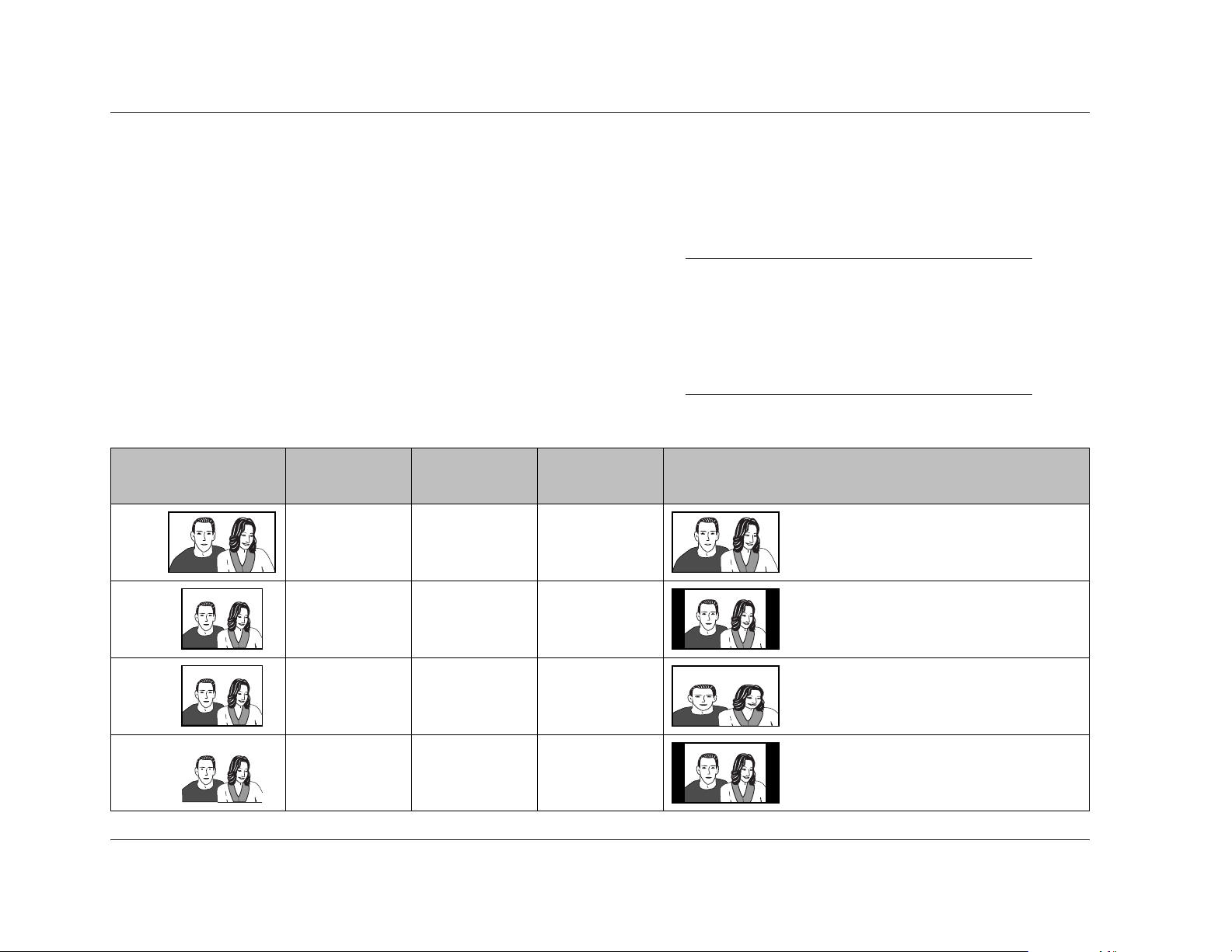
Setup Menus
Lexicon
3-26
setting, and the TV Type prompt Standard (4:3) setting is equivalent
to the TV Screen parameter 4:3 (Letter Box) setting. The TV Screen
parameter also offers settings for 16:9 (Compressed) and 4:3
(Pan&Scan) viewing. Refer to the table on pages 3-25 and below
for more information.
Note:
• Some discs do not allow video output format
adjustments.
• Neither the TV Screen parameter nor the TV Type
prompt can be adjusted when the RT-10 is in
playback mode.
Video1 (continued from page 3-25)
TV Screen (continued)
Select 16:9 (Wide) or 16:9 (Compressed) if the associated display
device screen has a 16:9 aspect ratio. Select Standard 4:3 (Letter
Box) or 4:3 (Pan&Scan) if the associated display device screen has
a 4:3 aspect ratio. The appearance of the picture depends on the
TV Screen parameter or TV Type prompt setting, the video output
format, the loaded disc, and display device settings.
The TV Screen parameter is associated with the Setup Navigator TV
Type prompt (3-5). The TV Type prompt Widescreen (16:9)
setting is equivalent to the TV Screen parameter 16:9 (Wide)
Video Recording
Format
TV Screen
Parameter
Display Device
Aspect Ratio
Display Device
Setting
Appearance
Normal (4:3)
Full (16:9)
Full (16:9)
Full (16:9)
16:9
16:9
16:9
16:9
16:9 (Wide)
16:9 (Wide)
Images appear in widescreen (16:9) format.
16:9
Images appear between black bars at either side of
the screen.
Images appear stretched across the screen. It is
recommended to set the display device to Normal
(4:3).
Images appear between black bars at either side of
the screen. This setting is recommended for display
devices with a fixed aspect ratio and a progressivescan component video input connector.
4:3
16:9 (Wide)
16:9 (Compressed)
4:3
4:3
Page 67

Setup Menus
RT-10
3-27
Component Video Progressive, Interlace
Controls component video output format when the RT-10 is using
the component video output connectors. Select Progressive if the
associated display device provides a progressive-scan component
video input connector. Select Interlace if the associated display
device does not provide a progressive-scan component video input
connector.
When Progressive is selected:
• The picture might appear stretched on the associated display
device screen if a video source recorded in 4:3 format is present
and the RT-10 or the display device is configured for a 16:9
aspect ratio. To correct this, configure the RT-10 or the
display device for a 4:3 aspect ratio. Refer to the TV Screen
parameter description on page 3-25 and the table on pages
3-25 and 3-26 for more information.
• The picture will not appear on the associated display device
screen if the display device does not provide a progressive-scan
component video input connector. To correct this, set the
Component Video parameter to Interlace and configure the
RT-10 for a different video output connection to the display
device.
• The RT-10 converts video sources recorded on film to 60
frames-per-second to create a more natural picture. Refer to
the Pure Cinema parameter description on page 3-30 for more
information.
• Progressive-scan component video output is only available
for NTSC discs.
Note:
The RT-10 is not compatible with all high-definition
display devices, which might produce video artifacts
in the picture.
Video Out Video, S-Video, RGB
Controls video output format when the RT-10 is using the Euro or
Peritel (TV A/V) connector. When Video is selected, the RT-10
passes composite video signals to the associated display device.
When S-Video is selected, the RT-10 passes S-video signals to the
associated display device. When RGB is selected, the RT-10 passes
RGB and composite video signals to the associated display device.
The composite video signals serve as sync.
. . . Video1 continues on page 3-28
TV Screen --- 16:9 (Wide)
Component Video --- Progressive
Video Out --- Video
S-Video Out --- S2
Frame Search --- Off
Screen Saver --- Off
Audio1 Language GeneralVideo1A2 V2
Move Exit
SETUP
Progressive
Interlace
Component Video
TV Screen --- 16:9 (Wide)
Component Video --- Progressive
Video Out --- Video
S-Video Out --- S2
Frame Search --- Off
Screen Saver --- Off
Audio1 Language GeneralVideo1A2 V2
Move Exit
SETUP
Video
S-Video
RGB
Video Out
Page 68

Setup Menus
Lexicon
3-28
Video1 (continued from page 3-27)
TV Screen --- 16:9 (Wide)
Component Video --- Progressive
Video Out --- Video
S-Video Out --- S2
Frame Search --- Off
Screen Saver --- Off
Audio1 Language GeneralVideo1A2 V2
Move Exit
SETUP
S1
S2
S-Video Out
TV Screen --- 16:9 (Wide)
Component Video --- Progressive
Video Out --- Video
S-Video Out --- S2
Frame Search --- Off
Screen Saver --- Off
Audio1 Language GeneralVideo1A2 V2
Move Exit
SETUP
On
Off
Frame Search
S-Video Out S1, S2
Determines the trigger control signal present when the RT-10 is
using the S-video output connector, providing control of
anamorphic display switching. Select the S1 setting to enable
automatic switching between 16:9 and 4:3 video output formats.
Select the S2 setting to enable automatic switching between 16:9,
4:3 standard, and 4:3 letter box video output formats.
The S-Video Out parameter controls anamorphic display
switching when all of the following conditions are met:
• The RT-10 has an S-video output connection to the associated
display device.
• The associated display device is compatible with the selected
anamorphic trigger control signal.
• The loaded disc supports the selected anamorphic trigger
control signal.
It is recommended to toggle between the S1 and S2 settings if the
picture appears stretched or otherwise distorted on the display
device screen.
Frame Search On, Off
Enables and disables the time and time & frame search modes
(4-28). When On is selected, these search modes are enabled for
compatible disc formats. When Off is selected, these search modes
are disabled for all disc formats.
Screen Saver On, Off
Activates and deactivates the Lexicon screen saver. When On is
selected, the Lexicon screen saver appears on the on-screen display
when a still frame image has appeared on the display device screen
for more than 5 minutes. When Off is selected, the Lexicon screen
saver does not appear on the on-screen display.
Note:
Still frame images displayed on CRT display devices
for long periods of time can "burn in" or create "ghost
images" on the screen. When the RT-10 is connected
to a CRT display device, it is recommended to set
the Screen Saver parameter to On to prevent the
appearance of "ghost images" on the screen.
TV Screen --- 16:9 (Wide)
Component Video --- Progressive
Video Out --- Video
S-Video Out --- S2
Frame Search --- Off
Screen Saver --- Off
Audio1 Language GeneralVideo1A2 V2
Move Exit
SETUP
On
Off
Screen Saver
Page 69

Setup Menus
RT-10
3-29
VIDEO2
Includes parameters that control video output format and
on-screen display appearance.
Background Gray, Black
Determines the background color of Setup menu screens when
resume or stop mode is activated. The video output signal appears
behind Setup menu screens when playback or pause mode is
activated.
Video Adjust Start
Opens the Video Adjust bar shown above, which can be used to
make exact, detailed adjustments of video settings such as
luminance (YNR), chrominance (CNR), mosquito (MNR), and black
(BNR) noise reduction, as well as sharpness, white, black, gamma,
hue, and chroma levels. Refer to the Video Adjust parameter
descriptions that begin on the next page for more information.
Note:
The remote control VIDEO ADJ button can also be
used to open the Video Adjust bar.
. . . Video2 continues on page 3-30
Possible SettingsDefault SettingParameter
Background Gray
Video Adjust N/A N/A
Still Picture* Auto • Field
• Frame
• Auto
On-Screen Display* On
•On
•Off
Angle Indicator* Off • On
•Off
•Gray
• Black
* These parameters only appear when the Setup menu is displayed in expert mode
(3-9 and 3-42).
Background --- Gray
Video Adjust
Still Playback --- Auto
On Screen Display --- On
Angle Indicator --- On
Audio1 Language GeneralV1A2 Video2
Move Exit
SETUP
Gray
Black
Background
Video Memory Select
Video Adjust
The loaded disc might cause the Video Adjust
bar to exceed on-screen display margins. If this
occurs, close the Video Adjust bar and remove
the loaded disc from the disc drawer. Then,
open the Video Adjust bar again.
Video Memory Select
Page 70

Video2 (continued from page 3-29)
Pure Cinema Auto1, Auto2, On, Off
Controls DVD-V frame rate to simulate cinema screen picture
quality. Video sources can be recorded on video or film. Sources
recorded on video have a 30 frames-per-second (NTSC) rate, and
sources recorded on film have a 24 frames-per-second rate. When
the Component parameter is set to Progressive, the RT-10 converts
sources recorded on film to 60 frames-per-second to create a more
natural picture.
Select Auto1 for most video sources. If the picture on the display
device screen appears unnatural, select another setting. Repeat this
process to achieve the best picture quality.
YNR (Luminance Noise Reduction) off to max
Controls the amount of noise reduction applied to the Y component
(luminance) present in video signals.
CNR (Chrominance Noise Reduction) off to max
Controls the amount of noise reduction applied to the C component
(chrominance) present in video signals.
MNR (Mosquito Noise Reduction) off to max
Controls the amount of noise reduction applied to mosquito (dot
crawl) noise present in video signals, which produces video artifacts
around picture edges as a result of MPEG compression.
BNR (Black Noise Reduction) off to max
Controls the amount of noise reduction applied to black noise
present in video signals.
Sharpness High soft to fine
Controls the sharpness of high-frequency (finely detailed) video
signals.
Sharpness Mid soft to fine
Controls the sharpness of mid-frequency (less detailed) video signals.
Detail off to max
Controls the sharpness of details around picture edges.
White Level min to max
Controls the white level of video signals.
Black Level min to max
Controls the black level of video signals.
Black Setup 0 IRE, 7.5 IRE
Corrects floating black color. Settings are based on International
Radio Engineer (IRE) units: 0 IRE is equivalent to 0.286V and 7.5 IRE
is equivalent to 0.339V.
Setup Menus
Lexicon
3-30
Page 71

Parameter
Setup Menus
RT-10
3-31
TV (CRT) PDP
Professional
Default Setting
Possible Settings
Pure Cinema
YNR
CNR
MNR
BNR
Sharpness High
Auto1
442
4
4
Sharpness Mid
Detail
White Level
Black Level
Black Setup
Gamma
4
444
4
444
Hue 444
Chroma Level 444
Chroma Delay
Memory
Prog. Motion
4
444
Off Off Off
44
7.5 IRE 7.5 IRE 7.5 IRE
44
6
4
4
0000
000
42
2
2
2
Auto1 Auto1 Auto1, Auto2, On, Off
off to max (8 increments)
off to max (8 increments)
off to max (8 increments)
off to max (8 increments)
soft to fine (8 increments)
soft to fine (8 increments)
off to max (8 increments)
min to max (8 increments)
min to max (8 increments)
0 IRE, 7.5 IRE
+ to – (8 increments)
green to red (8 increments)
min to max (8 increments)
+ to – (8 increments)
Off, 1, 2, 3
fast to slow (8 increments)
The RT-10 is manufactured for sale in several different countries. The default Video Adjust
parameter settings listed in the table shown above might differ among versions.
. . . Video2 continues on page 3-32
Page 72

Setup Menus
Lexicon
3-32
Chroma Delay min to max
Compensates for misalignment of the Y (luminance) and C
(chrominance) components present in video signals.
Memory Off, 1, 2, 3
Determines the memory bank in which user-defined Video Adjust
settings are stored. The RT-10 includes three memory banks called
1, 2, and 3.
To configure and store memory banks:
1. Press the remote control VIDEO ADJ button to open the Video
Adjust bar shown above (first column, first row).
Video Adjust (continued )
Gamma + to –
Controls the brightness of darker picture elements.
Hue green to red
Controls the red-to-green color balance of video sources.
Chroma Level min to max
Controls the color saturation of video sources.
Video2 (continued from page 3-31)
Video Memory Select
Video Adjust
Video Setup
PureCinema Auto1 Auto2 On Off
Move Select Check
Auto1
DISPLAYENTER
YNR Off max
Move Select Check
DISPLAYENTER
Detail Off max
Move Select Check
DISPLAYENTER
CNR Off max
Move Select Check
DISPLAYENTER
MNR Off max
Move Select Check
DISPLAYENTER
BNR Off max
Move Select Check
DISPLAYENTER
Sharpness High soft fine
Move Select Check
DISPLAYENTER
Sharpness Mid soft fine
Move Select Check
DISPLAYENTER
White Level min max
Move Select Check
DISPLAYENTER
Black Level min max
Move Select Check
DISPLAYENTER
Chroma Level min max
Move Select Check
DISPLAYENTER
Gamma + –
Move Select Check
DISPLAYENTER
Chroma Delay + –
Move Select Check
DISPLAYENTER
Prog. Motion fast slow
Move Select Check
DISPLAYENTER
Hue green red
Move Select Check
DISPLAYENTER
Black Setup 0IRE 7.5IRE
Move Select Check
7.5IRE
DISPLAYENTER
Memory Off 1 2 3
Move Select Check
Off
DISPLAYENTER
Page 73

Setup Menus
RT-10
3-33
2. When the Video Adjust bar opens, press the remote control
and arrows to highlight the Video Setup option. Then, press
the remote control ENTER button to select this option.
3. When the Video Setup bar opens:
• Proceed to step 4 to configure memory banks from the
Video Setup bars shown on the previous page. The Video
Setup bars allow Video Adjust parameters to be viewed on
17 separate bars.
• Press the remote control DISPLAY button to configure
memory banks from the Video Setup screens shown above.
The Video Setup screens allow Video Adjust parameters to
be viewed on two screens.
4. When the desired Video Setup view is selected, press the
and arrows to scroll through Video Adjust parameters.
• When a Video Setup bar is open, the selected parameter
appears on the bar.
• When a Video Setup screen is open, the selected parameter
is highlighted. The cursor automatically toggles between
the two screens when the last parameter on Page 1/2 or
the first parameter on Page 2/2 is passed.
Page 1/2
Prog. Motion fast slow
PureCinema Auto1 Auto2 On Off
YNR off max
CNR off max
MNR off max
BNR off max
Sharpness High soft fine
Sharpness Mid soft fine
Memory Off 1 2 3
Auto1PureCinema
Off
Page 2/2
Detail off max
White Level min max
Black Level min max
Black Setup 0IRE 7.5IRE
Gamma + –
Hue green red
Chroma Level min max
Chroma Delay + –
Memory Off 1 2 3
Detail
Off
7.5IRE
5. When the desired parameter is selected, press the and
arrows to adjust the setting. When the desired setting is selected,
press the and arrows to continue scrolling through Video
Adjust parameters.
6. Repeat steps 4 and 5 until all desired parameter settings have
been selected.
7. When all desired parameter settings have been selected, press
the and arrows to select the Memory parameter. Then,
press the and arrows to highlight the desired memory
bank (1, 2, or 3).
8. When the desired memory bank is highlighted, press the
ENTER button to select that bank. Its settings will be applied to
pictures on the display device screen until another Video Adjust
bank is selected or factory-default settings are restored.
• When Off is selected, the selected settings are applied to
the picture on the display device screen until a Video
Adjust bank is selected, factory-default settings are
restored, or the RT-10 is powered off with the front panel
On/Off button.
. . . Video2 continues on page 3-34
Page 74

Setup Menus
Lexicon
3-34
Video Adjust (continued )
Prog. Motion fast to slow
Controls the still picture quality when the RT-10 is using the
component video output connectors. This parameter is not
available unless the RT-10 is using the component video output
connectors.
Selecting Video Adjust Banks
The Video Memory Select bar shown above can be used to select
the desired Video Adjust bank. The RT-10 offers six banks of Video
Adjust settings, including three preset banks for CRT, plasma, and
professional display devices and three memory banks for storage of
user-defined Video Adjust settings. The Professional bank is
automatically selected when factory-default settings are restored.
To select a Video Adjust bank:
1. Press the remote control VIDEO ADJ button to open the Video
Adjust bar shown above (left).
2. When the Video Adjust bar opens, press the remote control
and arrows to highlight the Video Memory Select option.
Then, press the ENTER button to select this option.
3. When the Video Memory Select bar opens, press the , , ,
and arrows to highlight the desired Video Adjust bank.
• When a bank is highlighted, its settings are automatically
applied to the picture on the display device screen,
allowing for previewing of bank settings. These settings are
automatically unapplied when a new bank is selected or
the Video Memory Select bar is closed.
Note:
Depending on the loaded disc and the associated
display device, previewed Video Adjust bank settings
might not be unapplied when a new bank is
highlighted. If this occurs, it is required to select a new
Video Adjust bank to cancel the previewed settings.
The selected bank settings will be automatically
applied to the picture on the display device screen.
4. When the desired Video Adjust bank is highlighted, press
the ENTER button to select this bank. Its settings will be
automatically applied to the picture on the display device
screen.
Video2 (continued from page 3-33)
Video Memory Select
Video Adjust
Video Memory Select
TV(CRT) PDP Professional
Memory1 Memory2 Memory3
Professional
ENTER
Page 75

Angle Indicator On, Off
Activates and deactivates the indicator. When set to On, the
indicator appears on the front panel display when playback of a
scene recorded from multiple camera angles is in progress. When
set to Off, the indicator does not appear on the front panel
display when playback of a scene recorded from multiple camera
angles is in progress.
Note:
The remote control ANGLE button can be used to
select the desired camera angle for scenes recorded
from multiple camera angles (4-9).
Setup Menus
RT-10
3-35
Still Picture Field, Frame, Auto
Controls the appearance of still frame images. When Field is
selected, the RT-10 produces tight, stable, and generally shake-free
still frame images. When Frame is selected, the RT-10 produces
sharper, but shakier still frame images. When Auto is selected, the
RT-10 automatically selects the best viewing method for still frame
images.
On Screen Display On, Off
Controls the appearance of DVD top menus. When On is selected,
pressing the remote control TOP MENU button opens a DVD top
menu when the loaded DVD includes a top menu. (In some cases,
the remote control MENU button can also be pressed.) When Off
is selected, pressing the TOP MENU or MENU button does not
open a DVD top menu, even if the loaded DVD includes a top
menu. Refer to the Navigating Disc Menus section that begins on
page 4-3 for more information.
Background --- Gray
Video Adjust
Still Playback --- Auto
On Screen Display --- On
Angle Indicator --- On
Audio1 Language GeneralV1A2 Video2
Move Exit
SETUP
Field
Frame
Auto
Still Picture
Background --- Gray
Video Adjust
Still Playback --- Auto
On Screen Display --- On
Angle Indicator --- On
Audio1 Language GeneralV1A2 Video2
Move Exit
SETUP
On
Off
On Screen Display
Background --- Gray
Video Adjust
Still Playback --- Auto
On Screen Display --- On
Angle Indicator --- On
Audio1 Language GeneralV1A2 Video2
Move Exit
SETUP
On
Off
Angle Indicator
Page 76

Setup Menus
Lexicon
3-36
OSD Language English, français, Deutsch, Italiano, Español
Determines the language in which RT-10 on-screen display menus
appear. The OSD Language parameter is associated with the Setup
Navigator OSD Language prompt (3-4).
LANGUAGE
Includes parameters that can be used to determine RT-10 on-screen
display menu, disc menu, subtitle, and audio language.
Possible SettingsDefault SettingParameter
OSD Language English • English
• français
• Deutsch
• Italiano
• Español
Audio Language English • Refer to the table that
begins on page A-14
Subtitle Language English • Refer to the table that
begins on page A-14
Auto Language On • On
•Off
Subtitle Display* On
•On
•Off
• Assist Subtitle
Subtitle Off* Selected Subtitle
• With Audio
• Selected Subtitle
DVD Language* On
• w/ Subtitle Language
• Refer to the table that
begins on page A-14
* These parameters only appear when the Setup menu is displayed in expert mode
(3-9 and 3-42).
OSD Language --- English
Audio Language --- English
Subtitle Language --- English
Auto Language --- On
DVD Language --- English
Subtitle Display --- On
Subtitle Off --- Selected Subtitle
Audio1 Language GeneralVideo1A2 V2
Move Exit
SETUP
English
francais
Deutsch
Italiano
Espanol
OSD Language
Page 77

Setup Menus
RT-10
3-37
Audio Language Refer to the table on pages A-14 and A-15
Determines the language in which audio is heard. If the selected
audio language is available on the loaded DVD, the RT-10 selects
the audio track that includes that language. If the selected audio
language is not included on the loaded DVD, the RT-10 selects the
default disc audio language.
Select Other to choose a language other than English, French,
German, Italian, or Spanish. The DVD format recognizes 136
different languages, which are listed in the table that begins on
page A-14. When Other is selected, the Audio Language screen
shown above opens on the on-screen display.
To select an "Other" language:
1. When the Audio Language screen opens, use one of the
following methods to select the desired language:
a. Press the remote control and arrows to scroll through
the complete list of available languages. When the desired
language is highlighted, press the remote control ENTER
button to select this language and return to the Language
tab.
b. Press the remote control arrow to move the cursor to
the first character space that appears on the right of the
on-screen display. Then, use the remote control number
buttons to enter the numeric code for the desired
language. Refer to the table that begins on page A-14 to
determine the appropriate numeric code. When the
desired language is selected, press the remote control
ENTER button to return to the Language tab.
Note the following:
• If the Auto Language parameter (3-39) is set to On, the RT-10
automatically selects the default disc audio track, regardless of
the Audio Language parameter setting.
• The remote control AUDIO button can be used to select the
desired audio track (audio language and output format) on the
loaded DVD. Refer to page 4-7 for more information.
. . . Language continues on page 3-38
OSD Language --- English
Audio Language --- English
Subtitle Language --- English
Auto Language --- On
DVD Language --- English
Subtitle Display --- On
Subtitle Off --- Selected Subtitle
Audio1 Language GeneralVideo1A2 V2
Move Exit
SETUP
English
French
German
Italian
Spanish
Other
Audio Language
List of Languages Code (0~2)
Audio Language
0
Audio1 Language GeneralVideo1A2 V2
Move Select Exit
+/– Return
en:English
ENTER SETUP
5 1 4
Page 78

Setup Menus
Lexicon
3-38
b. Press the remote control arrow to move the cursor to
the first character space that appears on the right of the
on-screen display. Then, use the remote control number
buttons to enter the numeric code for the desired
language. Refer to the table that begins on page A-14 to
determine the appropriate numeric code. When the
desired language is selected, press the remote control
ENTER button to return to the Language tab.
Note the following:
• In most cases, subtitles do not appear on the on-screen display
when the Subtitle Display parameter (3-40) is set to Off,
regardless of the Subtitle Language and Auto Language (next
page) parameter settings.
• If the Auto Language parameter is set to On, the RT-10
automatically selects the default disc subtitle language,
regardless of the Subtitle Language parameter setting.
• If the loaded disc does not include subtitles, subtitles do not
appear on the on-screen display, regardless of Language tab
parameter settings.
Subtitle Language Refer to the table on pages A-14 and A-15
Determines the language in which subtitles appear. If the selected
subtitle language is available on the loaded DVD, the RT-10 selects
that language. If the selected subtitle language is not included on
the loaded DVD, the RT-10 selects the default disc subtitle language.
Select Other to choose a language other than English, French,
German, Italian, or Spanish. The DVD format recognizes 136
different languages, which are listed in the table that begins on
page A-14. When Other is selected, the Subtitle Language screen
shown above opens on the on-screen display.
To select an "Other" language:
1. When the Subtitle Language screen opens, use one of the
following methods to select the desired language:
a. Press the remote control and arrows to scroll through
the complete list of available languages. When the desired
language is highlighted, press the remote control ENTER
button to select this language and return to the Language
tab.
Language (continued from page 3-37)
List of Languages Code (0~2)
Subtitle Language
0
Audio1 Language GeneralVideo1A2 V2
Move Select Exit
+/– Return
en:English
ENTER SETUP
5 1 4
OSD Language --- English
Audio Language --- English
Subtitle Language --- English
Auto Language --- On
DVD Language --- English
Subtitle Display --- On
Subtitle Off --- Selected Subtitle
Audio1 Language GeneralVideo1A2 V2
Move Select Exit
SETUPENTER
English
French
German
Italian
Spanish
Other
Subtitle Language
Other
Page 79

Setup Menus
RT-10
3-39
• The remote control SUBTITLE button can be used to select the
desired subtitle language on the loaded DVD. Refer to page
4-8 for more information.
Auto Language On, Off
Controls audio track and subtitle language selection. When On is
selected, the RT-10 automatically selects the default disc audio
track and subtitle language, regardless of the Audio Language
(3-37) and Subtitle Language (previous page) parameter settings.
When Off is selected, the RT-10 selects audio track and subtitle
language based on the Audio Language and Subtitle Language
parameter settings.
Note the following:
• In most cases, subtitles do not appear on the on-screen display
when the Subtitle Display parameter (3-40) is set to Off,
regardless of the Subtitle Language (previous page) and Auto
Language parameter settings.
• If the loaded disc does not include subtitles, subtitles do not
appear on the on-screen display, regardless of Language tab
parameter settings.
DVD Language Refer to the table on pages A-14 and A-15
Determines the language in which DVD menus and top menus
appear. If the selected DVD menu language is available on the
loaded DVD, the RT-10 selects that language. If the selected DVD
menu language is not included on the loaded DVD, the RT-10
selects the default disc menu language. When w/ Subtitle
Language is selected, DVD menus appear in the selected subtitle
language.
Select Other to choose a language other than English, French,
German, Italian, or Spanish. The DVD format recognizes 136
different languages, which are listed in the table that begins on
page A-14. When Other is selected, the DVD Language screen
shown above opens on the on-screen display.
. . . Language continues on page 3-40
List of Languages Code (0~2)
DVD Language
0
Audio1 Language GeneralVideo1A2 V2
Move Select Exit
+/– Return
en:English
ENTER SETUP
5 1 4
OSD Language --- English
Audio Language --- English
Subtitle Language --- English
Auto Language --- On
DVD Language --- English
Subtitle Display --- On
Subtitle Off --- Selected Subtitle
Audio1 Language GeneralVideo1A2 V2
Move Select Exit
SETUP
ENTER
w/Subtitle Language
English
French
German
Italian
Spanish
Other
DVD Language
Other
OSD Language --- English
Audio Language --- English
Subtitle Language --- English
Auto Language --- On
DVD Language --- English
Subtitle Display --- On
Subtitle Off --- Selected Subtitle
Audio1 Language GeneralVideo1A2 V2
Move Exit
SETUP
On
Off
Auto Language
Page 80

Setup Menus
Lexicon
3-40
Note:
Some DVDs allow menu language to be selected from
the disc menu. Refer to page 4-3 for more
information.
Subtitle Display On, Off, Assist Subtitle
Controls the appearance of subtitles on the on-screen display.
Select On to display subtitles when playback mode is activated.
Select Off to prevent subtitles from displaying when playback
mode is activated. Select Assist Subtitle to display more extensive
subtitles when playback mode is activated.
Note the following:
• In most cases, subtitles do not appear on the on-screen display
when the Subtitle Display parameter is set to Off, regardless of
the Subtitle Language (3-38) and Auto Language (3-39)
parameter settings.
To select an "Other" language:
1. When the DVD Language screen opens, use one of the
following methods to select the desired language:
a. Press the remote control and arrows to scroll through
the complete list of available languages. When the desired
language is highlighted, press the remote control ENTER
button to select this language and return to the Language
tab.
b. Press the remote control arrow to move the cursor to
the first character space that appears on the right of the
on-screen display. Then, use the remote control number
buttons to enter the numeric code for the desired
language. Refer to the table that begins on page A-14 to
determine the appropriate numeric code. When the
desired language is selected, press the remote control
ENTER button to return to the Language tab.
Language (continued from page 3-39)
OSD Language --- English
Audio Language --- English
Subtitle Language --- English
Auto Language --- On
DVD Language --- English
Subtitle Display --- On
Subtitle Off --- Selected Subtitle
Audio1 Language GeneralVideo1A2 V2
Move Exit
SETUP
On
Off
Assist Subtitle
Subtitle Display
OSD Language --- English
Audio Language --- English
Subtitle Language --- English
Auto Language --- On
DVD Language --- English
Subtitle Display --- On
Subtitle Off --- Selected Subtitle
Audio1 Language GeneralVideo1A2 V2
Move Exit
SETUP
With Audio
Selected Subtitle
Subtitle Off
Page 81

• If the loaded disc does not include subtitles, subtitles do not
appear on the on-screen display, regardless of Language tab
parameter settings.
Subtitle Off With Audio, Selected Subtitle
Determines the language in which subtitles appear if the loaded
disc displays subtitles when the Subtitle Display parameter
(previous page) is set to Off. In most cases, subtitles do not appear
on the on-screen display when the Subtitle Display parameter is set
to Off, regardless of the Subtitle Language (3-38) and Auto
Language (3-39) parameter settings.
Select With Audio to display subtitles in the language selected with
the Audio Language parameter. Select Selected Subtitle to display
subtitles in the language selected with the Subtitle Language
parameter. If the loaded disc does not include the selected subtitle
language, the RT-10 selects the default disc subtitle language.
Setup Menus
RT-10
3-41
Possible SettingsDefault SettingParameter
Setup Menu Mode Expert • Expert
• Basic
Setup Navigator N/A N/A
Parental Lock N/A N/A
Bonus Group* N/A N/A
Auto Disc Menu* On
•On
•Off
Group Playback* Single
• All
• Single
* These parameters only appear when the Setup menu is displayed in expert mode
(3-9 and 3-42).
. . . General continues on page 3-42
GENERAL
Includes parameters that can be used to configure general RT-10
settings, such as Setup menu display mode, parental lock controls,
and DVD-A playback.
Page 82

Possible SettingsDefault SettingControl
Setup Menus
Lexicon
3-42
Parental Lock Password, Level, Country Code
Opens the Password, Level, and Country Code controls, which can
be used to assign a user-defined password that must be entered
before the RT-10 will activate playback mode when a disc encoded
with a user-defined security level is loaded. These controls have no
effect when a disc that is not encoded with a security level or
country code is loaded.
Setup Menu Mode Expert, Basic
Determines the mode in which the Setup menu is displayed. Select
Expert to display the Setup menu in expert mode, which includes
all available parameters. The Setup menu is shown in expert mode
at the top of page 3-10. Select Basic to display the Setup menu in
basic mode, which only includes parameters that are required to
configure the most common RT-10 settings. When displayed in
basic mode, the Setup menu also includes a tutorial to describe the
highlighted menu item. The Setup menu is shown in basic mode
at the bottom of page 3-10.
Setup Navigator Start
Activates and deactivates the Setup Navigator, which can be used
to configure basic RT-10 settings without navigating through the
entire Setup menu. Select Start to activate the Setup Navigator and
proceed to the OSD Language prompt (3-4). The Setup Navigator
parameter is associated with the Setup Navigator prompt (3-4).
General (continued from page 3-41)
Setup Menu Mode --- Expert
Setup Navigator
Parental Lock --- Off(us)
Bonus Group
Auto Disc Menu --- On
Group Playback --- Single
Audio1 Language GeneralVideo1A2 V2
Move Exit
SETUP
Expert
Basic
Setup Menu Mode
Setup Menu Mode --- Expert
Setup Navigator
Parental Lock --- Off(us)
Bonus Group
Auto Disc Menu --- On
Group Playback --- Single
Audio1 Language GeneralVideo1A2 V2
Move Exit
SETUP
StartSetup Navigator
Password None • None
• User-Defined*
Level off(us) • off(country code)
• 1 to 8
Country Code us(2119) • Refer to the table on page
A-16
* A user-defined password must be selected before the Level and Country Code controls
can be adjusted.
Page 83

Setup Menus
RT-10
3-43
Password
Assigns a user-defined password that must be entered before the
RT-10 will activate playback mode when a disc encoded with a
user-defined security level or country code is loaded. A user-defined
password must be assigned before the Level and Country Code
controls can be adjusted. User-defined passwords are automatically
deleted when factory-default settings are restored.
To assign a password:
When the Password parental control is selected for the first time,
the Register Code Number screen shown above opens on the
on-screen display. This screen can be used to assign a user-defined
password.
1. When the Register Code Number screen opens, use the remote
control number buttons to enter the desired password. All
passwords must consist of four numbers between 0 and 9.
• When a number is entered, the cursor automatically
advances to the next character space. Press the arrow to
return to the previous character space or the arrow to
advance to the next character space.
2. When a four-number password has been entered, an
ENTER button appears on the on-screen display to indicate
that pressing the remote control ENTER button will assign
the entered password.
. . . General continues on page 3-44
Parental Lock: Register Code Number
–
Audio1 Language GeneralVideo1A2 V2
Move Exit
+/– Return
SETUP
– – –
Setup Menu Mode --- Expert
Setup Navigator
Parental Lock --- Off(us)
Bonus Group
Auto Disc Menu --- On
Group Playback --- Single
Audio1 Language GeneralVideo1A2 V2
Move Select Exit
SETUPENTER
Password
Level
Country Code
Parental Lock Password
Parental Lock: Register Code Number
1
Audio1 Language GeneralVideo1A2 V2
Move Exit
+/– Return
ENTER
SETUP
2 3 4
ENTER
ENTER
3
21
6
54
+10
9
87
0
Page 84

Setup Menus
Lexicon
3-44
• When a number is entered, the cursor automatically
advances to the next character space. Press the arrow to
return to the previous character space or the arrow to
advance to the next character space.
• The number entered in the selected character space
appears as an actual number. Numbers entered in
unselected character spaces appear as asterisks as shown
above.
2. When the assigned password has been entered, an ENTER
button appears on the on-screen display to indicate that
pressing the remote control ENTER button will confirm the
password.
• If the assigned password has been entered, pressing the
ENTER button closes the Confirm Code Number screen
and opens the appropriate control screen.
• If an incorrect password has been entered, pressing the
ENTER button does not close the Confirm Code Number
screen. Instead, the ENTER button grays and the cursor
returns to the first character space.
Password (continued)
To confirm the user-defined password:
When a user-defined password is assigned, that password must be
entered before the RT-10 will activate playback mode when a disc
encoded with a user-defined security level is loaded. The
user-defined password must also be entered before the Level and
Country Code controls can be adjusted.
Note:
If the assigned password is lost or forgotten, factorydefault settings must be restored to delete the
password (5-16). Then, a new password can be
entered.
1. When the Confirm Code Number screen opens, use the
remote control number buttons to enter the assigned
password.
ENTER
3
21
6
54
+10
9
87
0
Parental Lock: Confirm Code Number
–
Audio1 Language GeneralVideo1A2 V2
Move Exit
+/– Return
SETUP
– – –
Parental Lock: Confirm Code Number
*
Audio1 Language GeneralVideo1A2 V2
Move Exit
+/– Return
ENTER
SETUP
* * *
General (continued from page 3-43)
Page 85

Setup Menus
RT-10
3-45
To assign a new password:
When a user-defined password is assigned, that password must be
entered before a new password can be assigned. When the current
password is confirmed, the Parental Lock: Password Change screen
opens on the on-screen display.
Note:
If the assigned password is lost or forgotten, factorydefault settings must be restored to delete the
password (5-16). Then, a new password can be
entered.
1. When the Parental Lock: Password Change screen opens, use
the remote control number buttons to enter the new
password.
• When a number is entered, the cursor automatically
advances to the next character space. Press the arrow to
return to the previous character space or the arrow to
advance to the next character space.
2. When the new password has been entered, an ENTER button
appears on the on-screen display to indicate that pressing the
remote control ENTER button will assign the password.
Level 1 to 8, off(country code)
Assigns a user-defined security level, requiring the password before
the RT-10 will activate playback mode when a disc encoded with a
user-defined security level is loaded. The Level control has no effect
when a disc that is not encoded with a security level is loaded.
Select a number within the 1 to 8 range to assign a security level.
The 1 setting represents the highest level of security, and the 8
setting represents the lowest level of security. When a security level
is assigned, the RT-10 requires the user-defined password before
activating playback mode when a disc encoded with a higher
security level is loaded.
. . . General continues on page 3-46
Parental Lock: Password Change
–
Audio1 Language GeneralVideo1A2 V2
Move Exit
+/– Return
SETUP
– – –
Parental Lock: Password Change
1
Audio1 Language GeneralVideo1A2 V2
Move Exit
+/– Return
ENTER
SETUP
2 3 4
ENTER
3
21
6
54
+10
9
87
0
Page 86

Setup Menus
Lexicon
3-46
General (continued from page 3-45)
Level 12345678
Parental Lock: Level Change
Audio1 Language GeneralVideo1A2 V2
Move Enter Exit
Return
Off
SETUPSETUP
Setup Menu Mode --- Expert
Setup Navigator
Parental Lock --- Off(us)
Bonus Group
Auto Disc Menu --- On
Group Playback --- Single
Audio1 Language GeneralVideo1A2 V2
Move Select Exit
SETUPENTER
Password
Level
Country Code
Parental Lock
Level
Level (continued)
Select off to use the Country Code control to determine security
level. When off is selected, the RT-10 requires the user-defined
password before activating playback mode when a disc encoded
with an incompatible country code is loaded. The Country Code
parameter has no effect on discs that are not encoded with a
country code, regardless of the Level control setting.
To assign a security level:
When the Level control is selected, the assigned password must be
entered before a security level can be assigned. When the current
password is confirmed, the Parental Lock: Level Change screen
shown above opens on the on-screen display.
1. When the Parental Lock: Level Change screen opens, press the
remote control and arrows to increase and decrease the
assigned security level. The locks that appear on the on-screen
display "lock" when the associated security level is selected and
"unlock" when the associated security level is deselected.
2. When the desired security level has been selected, press the
remote control ENTER button to assign that security level and
close the Parental Lock: Level Change screen.
• If the off(country code) setting is selected, make sure the
desired country code is selected with the Country Code
control. Otherwise, no security level will be assigned.
Note:
The remote control CONDITION MEMO button can
be used to assign a specific security level for the
loaded disc. Refer to page 4-10 for more information.
ENTER
Page 87

Setup Menus
RT-10
3-47
ENTER
Country Code Refer to the table on page A-16
Assigns a security level based on country code, requiring the
password before the RT-10 will activate playback mode when a disc
encoded with an incompatible country code is loaded. The
Country Code control has no effect when the Level control is set
within its 1 to 8 range or when a disc that is not encoded with a
country code is loaded.
To assign a country code:
When the Country Code control is selected, the assigned password
must be entered before a country code can be assigned. When the
current password is confirmed, the Parental Lock: Country Code
screen shown above opens on the on-screen display.
1. When the Parental Lock: Country Code screen opens, use one
of the following methods to select the desired country code:
a. Press the remote control and arrows to scroll through
the complete list of available countries. When the desired
country is highlighted, press the remote control ENTER
button to select that country and return to the General
tab.
b. Press the remote control arrow to move the cursor to
the first character space that appears on the right of the
on-screen display. Then, use the remote control number
buttons to enter the numeric code for the desired country.
Refer to the table on page A-16 to determine the
appropriate numeric code. When the desired country is
selected, press the remote control ENTER button to return
to the General tab.
. . . General continues on page 3-48
Setup Menu Mode --- Expert
Setup Navigator
Parental Lock --- Off(us)
Bonus Group
Auto Disc Menu --- On
Group Playback --- Single
Audio1 Language GeneralVideo1A2 V2
Move Select Exit
SETUPENTER
Password
Level
Country Code
Parental Lock
Country Code
List of Codes Code (0~2)
Country Code
2
Audio1 Language GeneralVideo1A2 V2
Move Select Exit
+/– Return
us
ENTER SETUP
1 1 9
Page 88

Setup Menus
Lexicon
3-48
To enter DVD-A bonus group access codes:
1. When the Bonus Group: Key Number Input screen opens, use
the remote control number buttons to enter the bonus group
access code.
• When a number is entered, the cursor automatically
advances to the next character space. Press the arrow to
return to the previous character space or the arrow to
advance to the next character space.
2. When the access code has been entered, an ENTER button
appears on the on-screen display to indicate that pressing the
remote control ENTER button will confirm the access code.
Bonus Group Start
Opens the Bonus Group: Key Number Input screen shown above,
which can be used to enter DVD-A bonus group access codes. In
most cases, DVD-As include bonus groups that do not require an
access code. Often, these bonus groups can be accessed from the
disc menu. In other cases, DVD-As include bonus groups that
cannot be accessed without a four-number access code, which is
often located on the disc packaging. The Bonus Group parameter
is not available for other disc formats or for DVD-As that include
bonus groups that do not require an access code.
Note:
When playback of a DVD-A bonus group that
requires an access code is attempted, the Bonus
Group: Key Number Input screen automatically opens
if the access code has not been entered since the disc
was loaded, factory-default settings were restored, or
the RT-10 was powered on.
Setup Menu Mode --- Expert
Setup Navigator
Parental Lock --- Off(us)
Bonus Group
Auto Disc Menu --- On
Group Playback --- Single
Audio1 Language GeneralVideo1A2 V2
Move Exit
SETUP
StartBonus Group
General (continued from page 3-47)
Bonus Group: Key Number Input
1
Audio1 Language GeneralVideo1A2 V2
Move Exit
+/– Return
ENTER
SETUP
2 3 4
Bonus Group: Key Number Input
–
Audio1 Language GeneralVideo1A2 V2
Move Exit
+/– Return
SETUP
– – –
ENTER
ENTER
3
21
6
54
+10
9
87
0
Page 89

Setup Menus
RT-10
3-49
Auto Disc Menu On, Off
Enables and disables automatic opening of DVD menus and top
menus. This parameter has no effect on other disc formats or on
DVDs that do not include menus or top menus.
When On is selected, DVD menus and top menus automatically
open on the on-screen display when a DVD that includes menus or
top menus is loaded. When Off is selected, DVD menus and top
menus do not automatically open on the on-screen display when a
DVD that includes menus or top menus is loaded. In either case,
the remote control MENU and TOP MENU buttons can still be used
to open and close disc menus and top menus. Refer to the
Navigating Disc Menus section that begins on page 4-3 for more
information.
Note:
Some DVDs include menus and top menus that
automatically open on the on-screen display when
the disc is loaded, regardless of the Auto Disc Menu
parameter setting.
Group Playback All, Single
Controls playback of DVD-A groups. This parameter has no effect
on other disc formats or on DVD-As that include just one group of
tracks.
DVD-As can include up to nine groups of tracks. Select All to
automatically begin playback of the next group when playback of
the selected group ends. Playback will continue until playback of
the disc ends. Select Single to automatically activate stop mode
when playback of the selected group ends. In some cases, the disc
menu or top menu will open on the on-screen display when
playback ends.
Note:
When the disc menu or top menu is used to select a
group for playback, stop mode is automatically
activated when playback of the selected group ends,
regardless of the Group Playback parameter setting.
Setup Menu Mode --- Expert
Setup Navigator
Parental Lock --- Off(us)
Bonus Group
Auto Disc Menu --- On
Group Playback --- Single
Audio1 Language GeneralVideo1A2 V2
Move Exit
SETUP
On
Off
Auto Disc Menu
Setup Menu Mode --- Expert
Setup Navigator
Parental Lock --- Off(us)
Bonus Group
Auto Disc Menu --- On
Group Playback --- Single
Audio1 Language GeneralVideo1A2 V2
Move Exit
SETUP
All
Single
Group Playback
Page 90

Setup Menus
Lexicon
3-50
• If a shortcut cannot be created for the highlighted
parameter, the icon shown at the right will
appear on the on-screen display. Shortcuts cannot
be created for the Setup menu parameters listed
in the Note: in the previous column.
To use a Setup menu shortcut:
1. If the Setup menu is closed, proceed to step 2. If the Setup
menu is open, press the remote control SETUP button to close
the Setup menu. Setup menu shortcuts cannot be used when
the Setup menu is open.
2. When the Setup menu is closed, press the remote control
F.MEMO button to open the Function Memory tab shown
above. The Function Memory tab lists all Setup menu
parameters for which a shortcut has been created.
3. When the Function Memory tab opens, press the remote
control and arrows to highlight the desired shortcut.
Then, press the remote control ENTER button to select that
shortcut. The Setup menu will open on the on-screen display,
highlighting the corresponding parameter.
SETUP MENU SHORTCUTS
The remote control F.MEMO button can be used to create up to
five shortcuts for Setup menu parameters. These shortcuts provide
convenient access to frequently adjusted Setup menu parameters
without navigating through the entire Setup menu.
Note:
Shortcuts cannot be created for the following Setup
menu parameters: Linear PCM Out, SACD Playback,
TV Screen, Audio Language, Subtitle Language, Auto
Language, DVD Language, Subtitle Display, Subtitle
Off, Setup Navigator, Parental Lock, Bonus Group,
and Group Playback.
To create and delete Setup menu shortcuts:
1. When the Setup menu is open, highlight the desired parameter
for which to create or delete a shortcut.
• Shortcuts can be created for up to five Setup menu
parameters, excluding those listed in the Note: above.
• Shortcuts can be deleted for Setup menu
parameters for which a shortcut has been
created. The icon shown at the right appears
to the left of the parameter label when a
shortcut has been created for that parameter.
2. When the desired parameter is highlighted, press the remote
control F.MEMO button.
• If a shortcut can be created for the highlighted parameter
the icon shown above will appear to the left of the
parameter label.
• If a shortcut has already been created for the highlighted
parameter, the icon will shown above disappear from the
left of the parameter label.
Parameter 1
Parameter 2
Parameter 3
Parameter 4
Parameter 5
Function Memory
Parameter 1
FM
Page 91

Setup Menus
RT-10
3-51
The Advanced Setup menu can be used to configure advanced
RT-10 mode settings for CD, SACD, and MP3 display mode,
standby mode, and remote control command mode. Unlike the
Setup menu, the Advanced Setup menu opens on the front panel
display, which provides one-line viewing of parameters and settings
as shown above.
DISP_MODE DISP_OFF DISP_ON
AUTO_P_OFF
REMOT_CODE
ENTER
OFF ON_30MIN
ENTER
DVD_1 DVD_2
ENTER
ADVANCED SETUP MENU
Possible SettingsDefault SettingParameter
DISP_MODE DISP_OFF • DISP_OFF
• DISP_ON
AUTO_P ON_30MIN • OFF
• ON_30MIN
REMOT_CODE DVD_2 • DVD_1
• DVD_2
. . . Advanced Setup Menu continues on page 3-52
Page 92

Setup Menus
Lexicon
3-52
DISP_MODE DISP_ON, DISP_OFF
Determines the front panel display mode for SACD, CD, and MP3
playback. This parameter setting has no effect when other disc
formats are loaded.
Select DISP_ON to deactivate the front panel display and rear panel
video output connectors during SACD, CD, and MP3 playback.
When SACD, CD, or MP3 playback is activated, press the front
panel Display Off button or the remote control DIMMER button to
activate the front panel display for 3 seconds. When stop mode is
activated, the front panel display remains activated until playback
resumes. The video output connectors remain deactivated until the
DISP_MODE parameter is set to DISP_OFF.
Select DISP_OFF to activate the front panel display and rear panel
video output connectors during SACD, CD, and MP3 playback. The
front panel display and rear panel video output connectors will
function as normal.
Note:
The DISP_MODE parameter might not function as
described with some SACDs, CDs, or MP3s. If this
occurs, set the DISP_MODE parameter to DISP_OFF so
the front panel display and rear panel video output
connectors will function as normal.
AUTO_P ON_30MIN, OFF
Enables and disables automatic standby mode activation. When
ON_30MIN is selected, the RT-10 automatically activates standby
mode after 30 minutes of non-use. When OFF is selected, the RT-10
does not automatically activate standby mode after 30 minutes of
non-use.
Advanced Setup Menu (continued from page 3-51)
To open the Advanced Setup menu:
1. Press the Stop button to activate stop mode. In some cases, the
Stop button must be pressed twice in succession to activate
stop mode.
2. If the Setup menu is closed, proceed to step 3. If the Setup
menu is open, press the remote control Setup button to close
the Setup menu. The Advanced Setup menu is not available
when the Setup menu is open.
3. When stop mode is activated and the Setup menu is closed,
press and hold the SETUP button for about 2 seconds. The
front panel Display Off button LED will begin blinking,
indicating that the Advanced Setup menu is open on the front
panel display.
• When the Advanced Setup menu is open, the DISP_MODE
parameter appears on the front panel display as shown on
the previous page (first column, first row).
To navigate the Advanced Setup menu:
Button Command
ENTER Selects the highlighted parameter or setting.
and Scroll upward and downward through
parameters. When a parameter is selected,
pressing the and arrows scrolls upward
and downward through parameter settings.
SETUP Closes the Advanced Setup menu.
Page 93

Setup Menus
RT-10
3-53
REMOT_CODE DVD_1, DVD_2
Assigns a remote control command mode to the RT-10. When
DVD_1 is selected, the RT-10 can be operated with an RT-10
remote control to which the DVD_1 command mode is also
assigned. When DVD_2 is selected, the RT-10 can be operated with
an RT-10 remote control to which the DVD_2 command mode is
also assigned.
Assigning Remote Control Command Modes
The RT-10 remote control can be used to operate two RT-10s
installed in the same system when the DVD_1 command mode is
assigned to one RT-10 and the DVD_2 command mode is assigned
to the other RT-10. These command modes can also be assigned to
the remote control, allowing the remote control to operate an
RT-10 to which the same command mode is assigned. The remote
control cannot be used to operate an RT-10 to which a different
command mode is assigned, except to configure Advanced Setup
menu parameter settings.
Note:
The DVD_1 command mode is intended for use when
two RT-10s are installed in the same system.
Otherwise, avoid assigning the DVD_1 command
mode to the RT-10 and the RT-10 remote control.
When one RT-10 is installed in the system, follow the instructions
in the next column to assign the DVD_2 command mode to the
remote control and the RT-10. The DVD_2 command mode is
assigned to the RT-10 when factory-default settings are restored.
The command mode assigned to the remote control is not affected
when factory-default settings are restored.
When two RT-10s are installed in the same system, follow the
instructions below to assign the DVD_1 command mode to one
RT-10 and the DVD_2 command mode to the other RT-10. Follow
the instructions below to toggle the command mode assigned to
the remote control, allowing the remote control to provide
independent operation of both RT-10s.
To assign the DVD_2 command mode to the remote control:
Press and hold the remote control STOP and number 2 buttons
for about 5 seconds.
To assign the DVD_1 command mode to the remote control:
Press and hold the remote control STOP and number 1 buttons
for about 5 seconds.
To confirm the command mode assigned to the remote control:
Press and hold the remote control STOP and PAUSE buttons for
about 2 seconds. The command mode assigned to the remote
control will appear on the front panel display.
To assign a command mode to the RT-10:
Follow the navigation instructions on the previous page to set the
REMOT_CODE parameter to the desired command mode.
Page 94

4
Playback Controls
Playback Icons . . . . . . . . . . . . . . . . . . . . . . . . . . . . . . . . . . . . . . . . . . . 4-2
Loading Discs . . . . . . . . . . . . . . . . . . . . . . . . . . . . . . . . . . . . . . . . . . . . 4-2
Navigating Disc Menus . . . . . . . . . . . . . . . . . . . . . . . . . . . . . . . . . . . . . 4-3
Selecting Disc Settings . . . . . . . . . . . . . . . . . . . . . . . . . . . . . . . . . . . . . 4-7
Audio Tracks • Subtitle Languages • Camera Angles • Storing Disc Settings
Playback Modes . . . . . . . . . . . . . . . . . . . . . . . . . . . . . . . . . . . . . . . . . 4-11
Playback • Last Memory Playback • Stop Mode • Resume Mode • Pause Mode • Still
Frame Playback • Frame-by-Frame Playback • Slow Playback • Random Playback •
Repeat Playback • A-B Repeat Playback • Program Mode • Search Mode • Display
Mode
Page 95

Playback Controls
Lexicon
4-2
Note the following:
• The RT-10 is compatible with DVD-V, DVD-A, DVD-RW/R,
SACD, Audio CD, CD-RW/R, Video CD, SVCD, and MP3 formats
that meet the requirements outlined in the Disc Compatibility
section (1-5). The RT-10 is not compatible with DVD-ROM,
DVD-RAM, CD-ROM (except those that include MP3 tracks),
and Photo CD formats.
• The RT-10 is compatible with 5-inch (12cm) and 3-inch (8cm)
conventional, round discs. Do not attempt to load discs with
other size and shape characteristics, such as those shown
below. All discs must align with the circular guide inside the
disc drawer.
PLAYBACK ICONS
• The icon shown at the right appears on the
on-screen display when the RT-10 does not allow the
selected command.
• The icon shown at the right appears on the
on-screen display when the loaded disc does not
allow the selected command.
LOADING DISCS
Discs require special care and handling to ensure optimal
performance. When loading discs, pay particular attention to the
bulleted items that begin in the next column and to other
precautions that appear throughout this user guide. Refer to the
Disc Compatibility (1-5), Disc Care & Handling (1-8), and Disc
Maintenance (5-16) sections for more information.
The RT-10 is a single-disc player. Do not attempt to load more
than one disc in the disc drawer at one time. This might cause
damage to the RT-10, the discs, or both.
Dirty or damaged discs such as those shown below might
affect playback performance or damage the RT-10. Do not
attempt to load cracked, chipped, scratched, warped, dirty, or
otherwise damaged discs in the disc drawer.
CAUTION
• Hold discs at their center hole and outer edges as shown
below. Take care not to leave fingerprints, dirt, or scratches on
disc surfaces.
• Load single-sided discs with the label side facing upward and
double-sided discs with the side intended for playback facing
downward.
• Return discs to their cases when not in use. Discs should be
stored in an upright position out of direct sunlight and
excessive heat, humidity, or cold.
Page 96

Playback Controls
RT-10
4-3
• The RT-10 will attempt to load a disc whenever the disc drawer
is closed, even when the disc drawer is empty.
To load a disc:
1. Review the bulleted items that begin on the previous page.
2. Press the Open/Close button to open the disc drawer.
3. If the disc drawer is not empty, remove the disc loaded in the
disc drawer (if applicable).
• The RT-10 is a single-disc player. Do not attempt to load
more than one disc in the disc drawer at one time. This
might cause damage to the RT-10, the discs, or both.
4. When the disc drawer is empty, load the desired disc in the disc
drawer.
• Load single-sided discs with the label side facing upward
and double-sided discs with the side intended for playback
facing downward. All discs must align with the circular
guide inside the disc drawer.
5. When the desired disc has been loaded, press the Open/Close
button to close the disc drawer. The disc drawer can also be
closed with a gentle press against the front of the disc drawer.
NAVIGATING DISC MENUS
Most discs include on-screen display menus that can be used to
select disc settings, control playback, or view information about the
disc. The descriptions that begin below provide a general overview
of disc menus available for each disc format.
Note:
This descriptions that begin below provide a general
overview of disc menus available for each disc format.
These descriptions might differ for some discs within
each format.
DVD-V
Include menus that can be used to activate playback of specific
scenes and to select disc settings such as audio track (audio
language and output format), subtitle language, and camera
angle. In some cases, certain remote control buttons can also be
used to select these settings without navigating through the disc
menu (4-7).
DVD-A
Include top menus that can be used to activate playback of specific
tracks and to select disc settings such as output format.
DVD-RW/R
Include an Original List screen that provides information about the
contents of the disc as recorded. Some discs also include a Play List
screen that provides information about the contents of the disc as
programmed.
. . . Navigating Disc Menus continues on page 4-4
Page 97

Playback Controls
Lexicon
4-4
No. Description
1 Indicates the numbers of the currently playing folder
and track. The MP3 Navigator does not provide this
information unless playback is activated.
2 Indicates the number of the selected folder and the
number of folders included on the loaded disc. The
RT-10 recognizes a maximum of 250 folders per disc.
It ignores all folders that exceed this number.
3 Indicates the number and name assigned to each
folder on the loaded disc.
4 Indicates the number of the selected track and the
number of tracks included in the selected folder. The
RT-10 recognizes a maximum of 250 tracks per folder.
It ignores all folders that exceed this number.
5 Indicates the number and name assigned to each
track in the selected folder.
To navigate disc menus:
The table on pages 4-5 and 4-6 provides a general overview of
remote control commands that can be used to navigate disc
menus. In most cases, the remote control button must be
pressed while the menu is open. Otherwise, the button executes
the command indicated in the Command Matrix that begins on
page 2-15. In some cases, the command indicated in the
Command Matrix can also be used when the menu is open.
Note the following:
• The table on pages 4-5 and 4-6 provides a general overview of
remote control commands that can be used to navigate disc
menus. Some commands might not be available for all discs
within each format.
Navigating Disc Menus (continued from page 4-3)
SACD, Audio CD, & CD-RW/R
These disc formats do not include disc menus. In some cases,
CD-RW/Rs that include MP3 tracks also include an MP3 Navigator
(below and 4-27).
Video CD & SVCD
Include PBC (Playback Control) menus that can be used to activate
playback of specific tracks. In some cases, the remote control
number buttons can also be used to activate playback of specific
tracks when the PBC menu is open.
MP3
Include an MP3 Navigator similar to the one shown below. The
MP3 Navigator can be used to edit the MP3 program list, activate
playback of specific folders and tracks, and view the MP3 file
structure.
Current: 1-1
1~10 Folder Track 1~4
1.TRACK1-1
2.TRACK2-2
3.TRACK3-3
4.TRACK4-4
MP3 Navigator
Play Exit
MENUENTER
1.FOLDER-1
2.FOLDER-2
3.FOLDER-3
4.FOLDER-4
5.FOLDER-5
6.FOLDER-6
51
2
3
4
Page 98

Button DVD-V & DVD-A DVD-RW/R Video CD & SVCD MP3
Playback Controls
RT-10
4-5
When a DVD-V is loaded, pressing the MENU button
opens and closes the disc menu, provided the
loaded disc includes a menu. In some cases, pressing
the TOP MENU button also opens and closes the
menu. When a DVD-A is loaded, pressing the TOP
MENU button opens and closes the disc top menu,
provided the loaded disc includes a top menu. The
TOP MENU button must be pressed to open and
close DVD-A top menus. Pressing the MENU button
performs no function.
Select the corresponding menu item. When menu
items are numbered, pressing a number button
selects the menu item with the corresponding
number. When menu items are not numbered,
pressing a number button selects the menu item in
the corresponding position. For instance, pressing
the number 1 button selects the first menu item.
Refer to page 2-15 for instructions to select menu
items 10 and above.
Perform no function. Same as DVD-V & DVD-A. In
some cases, pressing a number
button activates playback of
corresponding track when the
PBC menu is open.
Opens and closes the PBC menu,
provided the loaded disc includes
a PBC menu.
Perform no function.
Pressing the MENU button opens
and closes the disc menu,
provided the loaded disc includes
a menu. Pressing the TOP MENU
button performs no function.
Perform no function. Pressing the MENU button opens
and closes the MP3 Navigator,
provided the loaded disc
includes an MP3 Navigator.
Pressing the TOP MENU button
performs no function.
MENU &
TOP MENU
Number
Buttons
Performs no function.
Performs no function.
Selects the highlighted disc menu item.
Performs no function. Performs no function.
Performs no function.
Performs no function.
Same a DVD-V & DVD-A.
Performs no function.
Performs no function.
Closes the MP3 Navigator.
Deletes the selected track from
the MP3 program list (4-27).
Adds the selected track to the
MP3 program list (4-27).
Activates playback of the selected
track or the first track in the
selected folder.
CLEAR
PROGRAM
ENTER
Closes the current disc menu screen and opens the
previous menu screen. When the first menu screen is
open, pressing the RETURN button performs no
function. When a DVD-A is loaded, pressing the
RETURN button opens the browsable pictures,
provided the loaded disc includes browsable
pictures.
RETURN
Disc Menu Command Matrix
. . . Disc Menu Command Matrix continues on page 4-6
Page 99

Playback Controls
Lexicon
4-6
Button DVD-V & DVD-A DVD-RW/R Video CD & SVCD MP3
Scroll upward and downward through disc menu
items. In some cases, pressing the and arrows
scrolls left and right through menu items
Scroll left and right through disc menu items. In
some cases, pressing the and arrows scrolls
upward and downward through menu items.
Closes the current disc menu screen and opens the
previous menu screen. When the first menu screen is
open, pressing the PREV button performs no
function.
Same as DVD-V & DVD-A.
Same as DVD-V & DVD-A. Same as DVD-V & DVD-A.
Toggle between the Original List
and Play List screens when all of
the following conditions are met:
• The loaded disc includes
Original List and Play List
screens.
• Stop mode is activated.
• No menu items are selected.
When a menu item is selected,
pressing the arrow activates
playback at the first frame of
the selected menu item.
Perform no function.
Perform no function.
Perform no function. Perform no function. Perform no function.
Perform no function.
Same as DVD-V & DVD-A. Same as DVD-V & DVD-A. Perform no function.
When the folder list is selected,
pressing the and arrows
scrolls upward and downward
through the folder list. When the
track list is selected, pressing the
and arrows scrolls upward
and downward through the track
list.
Toggle between the folder and
track lists.
&
&
PREV
Closes the current disc menu screen and opens the
next menu screen. When the last menu screen is
open, pressing the NEXT button performs no
function.
When a DVD-V is loaded, pressing one of these
buttons opens the corresponding menu screen,
provided the loaded disc includes the corresponding
menu screen. When a DVD-A is loaded, pressing one
of these buttons performs no function.
NEXT
SEARCH,
AUDIO,
SUBTITLE, &
ANGLE
Disc Menu Command Matrix (continued from page 4-5)
Page 100

Playback Controls
RT-10
4-7
SELECTING DISC SETTINGS
Some disc menus can be used to select disc settings such as audio
track (audio language and output format), subtitle language, and
camera angle. In some cases, certain remote control buttons can
also be used to select these settings without navigating through
the disc menu.
Note:
Condition memory mode (4-10) stores audio
language, output format, subtitle language, and
camera angle settings for up to 15 DVD-Vs. Once
stored, these settings will be automatically recalled
whenever the disc is loaded.
AUDIO TRACKS
• Pressing the remote control AUDIO button opens one of the
Audio bars shown in the next column, which can be used to
select the desired audio track (audio language and output
format).
• Audio track selection is available for DVD-Vs, Video CDs, and
MP3s recorded with two or more audio tracks. Audio track
selection is not available for other disc formats or for discs
recorded with one audio track. In addition, audio track
selection is not available unless playback is activated.
• DVD-V and Video CD audio tracks include an audio language
and output format. MP3 audio tracks include an output format.
• Audio track selection has no effect on the Audio Language
parameter (3-37) setting.
AUDIO
To select an audio track:
1. When playback is activated, press the AUDIO button to open
one of the Audio bars shown below.
• When a DVD-V or Video CD is loaded, an Audio bar similar
to the one shown below will open at the top of the onscreen display, indicating the audio language and output
format in which the selected audio track was recorded. For
instance, the Audio bar shown below indicates that the
selected audio track was recorded in English in 2-channel
Dolby Digital format.
Dolby Digital
Audio :1 English 2CH
Audio : Stereo
Audio : 1/L
Audio : 2/R
• When an MP3 is loaded, one of the Audio bars shown
below will open at the top of the on-screen display,
indicating the output format in which the selected audio
track was recorded – stereo, mono, or 2-channel.
• If the Audio bar does not open at the top of the on-screen
display, audio track selection might not be available for the
loaded disc.
2. When the Audio bar opens, press the AUDIO button again to
cycle through all audio tracks available on the loaded disc. The
remote control number buttons can also be used to enter the
number of the desired audio track (if known).
. . . Audio Tracks continues on page 4-8
 Loading...