

Level Pro ITC 470 User Manual

USER MANUAL
METER
ITC 450 - ITC 470
ITC 450
ITC 470
Read the user's manual carefully before starting to use the unit or software.
Producer reserves the right to implement changes without prior notice.
www. levelprosales.com
www. levelprosales.com

ITC 450/470
User manual
TABLE OF CONTENTS
1. BASIC REQUIREMENTS AND USER SAFETY
2. GENERAL CHARACTERISTICS
3. TECHNICAL DATA
4. DEVICE INSTALLATION
4.1. UNPACKING
4.2. ASSEMBLY
4.3. CONNECTION METHOD
4.4. MAINTENANCE
5. FRONT PANEL DESCRIPTION
6. PRINCIPLE OF OPERATION
6.1. MEASUREMENT MODE
6.2. DETECTION OF THE PEAK VALUES
6.3. CONTROL OF THE RELAY OUTPUTS
6.3.1. One threshold mode
6.3.2. Two thresholds mode
7. DEVICE PROGRAMMING
7.1. PROGRAMMING MENU
7.2. PARAMETERS EDITION
7.2.1. Numeric parameters (digit change mode)
7.2.2. Numeric parameters (slide change mode)
7.2.3. Switch parameters (“LIST” type)
7.3. MENU DESCRIPTION
7.3.1. “rEL1” menu
7.3.2. “bEEP” menu
7.3.3. “inPt” menu (common parameters)
7.3.4. “inPt” menu (parameters of temperature inputs)
7.3.5. “inPt” menu (parameters of current and voltage inputs)
7.3.6. ”OutP” menu
7.3.7. ”bri” parameter
7.3.8. ”HOLd” menu
7.3.9. ”SECu” menu
7.3.10. ”rS” menu
7.3.11. ”Edit” parameter
7.3.12. ”dEFS” parameter
7.3.13. ”SErv” menu
7.4. MENU STRUCTURE
8. THE ALARM LED
9. OVER-CURRENT PROTECTION
10. DISPLAYED VALUES CALCULATION
10.1. ADDITIONAL CALCULATIONS (USED CONVERSION CHARACTERISTIC)
10.1.1. Linear characteristic
10.1.2. Square characteristic
10.1.3. Square root characteristic
10.1.4. User defined characteristic
10.2. EXAMPLES OF CALCULATIONS
11. THE MODBUS PROTOCOL HANDLING
11.1. LIST OF REGISTERS
11.2. TRANSMISSION ERRORS DESCRIPTION
11.3. EXAMPLES OF QUERY/ANSWER FRAMES
12. DEFAULT AND USER'S SETTINGS LIST
01
02
02
05
05
06
08
16
16
17
17
19
20
21
22
23
23
24
24
25
25
26
26
28
29
29
30
32
33
33
34
34
35
35
35
36
38
38
38
38
39
39
40
40
41
44
45
50
50
53
www. levelprosales.com
ITC 450/470
User manual
Explanation of symbols used in the manual:
This symbol denotes especially important guidelines concerning the installation and operation
of the device. Not complying with the guidelines denoted by this symbol may cause an accident,
damage or equipment destruction.
IF THE DEVICE IS NOT USED ACCORDING TO THE MANUAL THE USER IS
RESPONSIBLE FOR POSSIBLE DAMAGES.
This symbol denotes especially important characteristics of the unit. Read any information
regarding this symbol carefully.
1. BASIC REQUIREMENTS AND USER SAFETY
The manufacturer is not responsible for any damages caused by inappropriate installation, not maintaining the proper
environmental conditions and using the unit contrary to its assignment.
Installation should be conducted by qualified personnel . During installation all available safety requirements should be
considered. The fitter is responsible for executing the installation according to this manual, local safety and EMC regulations.
If the device is equipped with PE connector, it should be connected to PE wire. Otherwise PE wire should be connected to
GND connector.
unit must be properly set-up, according to the application. Incorrect configuration can cause defective operation, which
The
can lead to unit damage or an accident.
If in the case of a unit malfunction there is a risk of a serious threat to the safety of people or property additional,
independent systems and solutions to prevent such a threat must be used.
The unit uses dangerous voltage that can cause a lethal accident. The unit must be switched off and disconnected from the
power supply prior to starting installation of troubleshooting (in the case of malfunction).
Neighbouring and connected equipment must meet the appropriate standards and regulations concerning safety and be
equipped with adequate overvoltage and interference filters.
Do not attempt to disassemble, repair or modify the unit yourself. The unit
has no user serviceable parts. Defective units must be disconnected and submitted for repairs at an authorized service centre.
In order to minimize fire or electric shock hazard, the unit must be protected against atmospheric precipitation and excessive
humidity.
Do not use the unit in areas threatened with excessive shocks, vibrations, dust, humidity, corrosive gasses and oils.
Do not use the unit in areas where there is risk of explosions.
Do not use the unit in areas with significant temperature variations, exposure to condensation or ice.
Do not use the unit in areas exposed to direct sunlight.
Make sure that the ambient temperature (e.g. inside the control box) does not exceed the recommended values. In such
cases forced cooling of the unit must be considered (e.g. by using a ventilator).
The unit is designed for operation in an industrial environment and must not be used in a household
environment or similar.
www. levelprosales.com
www. levelprosales.com
01

ITC 450/470
User manual
2. GENERAL CHARACTERISTICS
The ITC 450/470 meter is equipped with one current input (0-20mA), two voltage inputs (0-10V and 0-150
mV), one RTD input (Pt 100/500/1000) and one TC input (thermocouple: K, S, J, T, N, R, B, E). Temperature of
cold ends is compensated automatically. RTD and TC inputs are fully linearised. It is allowed to use only one
input at the same time. Input ranges are described in the next chapter. Result is showed on 4-digit LED
display.
The device can be equipped with two or four relay (or OC type) outputs. Optionally ITC 450/470 with two
relays (or OC type) outputs can be equipped with active current output, passive isolated current output or
active voltage output. Device ITC 450/470 is equipped with RS-485 / Modbus RTU communication interface
and sensor supply output. The meter can be ordered in two power supply versions.
ITC 450/470 can be used for controlling and regulation of processes need proportional and threshold control
like: temperature processes (heating or cooling), valves controlling or other.
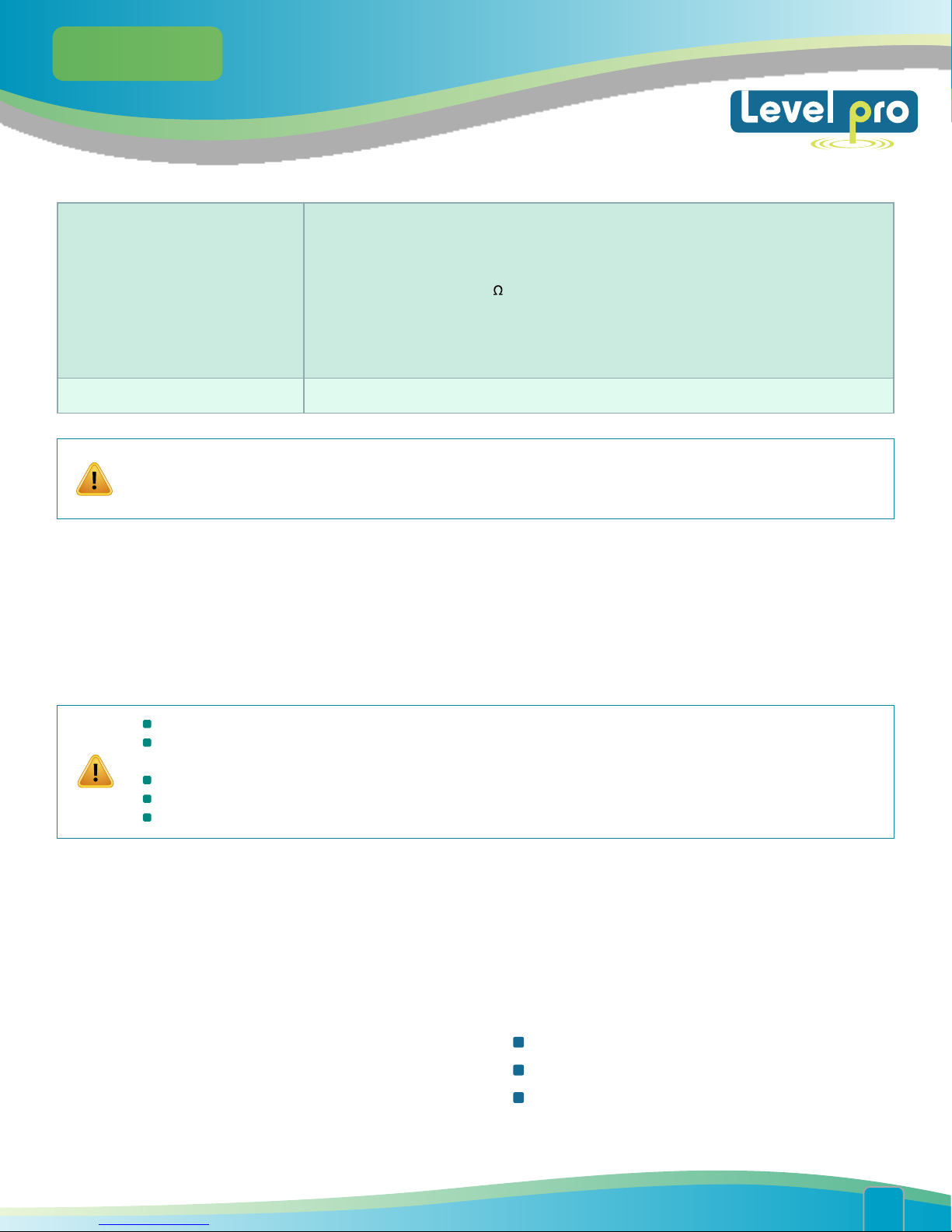
3. TECHNICAL DATA
Power supply voltage
(depending on version)
External fuse (required)
Power consumption
Current input (20 mA)
Current measurement accuracy
Current input resistance
Accepted prolonged
input overload
Voltage input (10V range)
Voltage measurement accuracy
Voltage input resistance
Accepted prolonged
input overload
85...230...260V AC/DC; 50 ÷ 60 Hz (separated)
or 19...24...50V DC and 16...24...35V AC (separated)
T - type, max. 2 A
max. 6.5 VA @ 85 ÷ 260V AC/DC
max. 6.5 VA @ 16V ÷ 35V AC
max. 6.5 W @ 19V ÷ 50V DC
0÷20 mA, 4÷20 mA overload protected, input current is limited to 50 mA (typically)
± 0.1% @ 25°C; ± one digit (for 0÷20 mA range)
< 65 (typical 30 )
20%
0÷5 V, 1÷5 V, 0÷10 V, 2÷10 V
± 0.1% @ 25°C; ± one digit (for 0÷10 V range)
> 100 kW (while maintaining correct polarization)
20%
Voltage input (150mV range)
Voltage measurement accuracy
Voltage input resistance
Accepted prolonged
input overload
0÷60 mV, 0÷75 mV, 0÷100 mV, 0÷150 mV
± 0.1% @ 25°C; ± one digit (for 0÷150 mV range)
> 1,5 M
20%
www. levelprosales.com
www. levelprosales.com
02

ITC 450/470
User manual
RTD input (resistive)
Measurement range
Measurement accuracy
Measurement wires resistance
Thermocouple input
Thermocouple input range
Measurement accuracy
Accuracy of cold ends
temperature compensation
Sensor power supply output
Pt 100, Pt 500,Pt 1000
-100°C ÷ +600°C
± 0,1% @ 25°C; ± one digit
max. 20 (every wire)
K, S, J, T, N, R, B, E
K: -200°C ÷ +1370¢ªC
S: -50°C ÷ +1768¢ªC
-210°C ÷ +1200¢ªC
J:
T: -200°C ÷ +400¢ªC
-200°C ÷ +1300¢ªC
N:
-50°C ÷ +1768¢ªC
R:
+250°C ÷ +1820¢ªC
B:
E: -200°C ÷ +1000¢ªC
K, J, E :± 0.1% @ 25°C; ± one digit
N :± 0.2% @ 25°C; ± one digit
T, R, B:± 0.5% @ 25°C; ± one digit
S,
± 1°C
24V +5%, -10% / max. 100 mA, stabilized
Relay output
OC-type output
Active current output
(optional, for two relays or two
OC-type output version only)
Load resistance max.
Passive isolated current output
(optional, for two relays or two
OC-type output version only)
Supply voltage
Load resistance max.
Active voltage output
(optional, for two relays or two
OC-type output version only)
Load resistance min.
0, 2 or 4 NO, 1A/250V AC (cos Ø = 1)
0, 2 or 4; 30mA / 30VDC / 100mW
range max. 0 ÷ 24 mA
700
range max. 2.8 ÷ 24 mA
Us = 9.5 ÷ 36V
(Us – 9.5V) / 24mA [k ]
range max. 0 ÷ 11V
2000
www. levelprosales.com
www. levelprosales.com
03

ITC 450/470
User manual
Temperature stability
Temperature stability
Communication interface
Baud rate
ITC 450 Display
(depending on version)
ITC 470 Display
(depending on version)
Data memory
Front panel protection
Terminals protection
Housing type
Housing material
50 ppm / °C
-999 ÷ 9999, plus decimal point
RS-485, 8N1 and 8N2, Modbus RTU, not separated
1200 bit/s ÷ 115200 bit/s
LED, 4 digit, 20mm height, red or
LED, 4 digit, 20mm height, green
LED, 4 digit, 20mm height, red or
LED, 4 digit, 20mm height, green
non-volatile memory, EEPROM type
IP 65
optional version with panel cut-out sealing available
IP 20
panel
NORYL - GFN2S E1
Housing dimensions
Mounting hole
Assembly depth
Panel thickness
Operating temperature
(depending on version)
Storage temperature
(depending on version)
Humidity
Altitude
Screws tightening max. torque
Max. connection leads
cross section
96 x 48 x 100 mm
90.5 x 43 mm
102 mm
max. 5 mm
0°C to +50°C
or -20°C to +50°C
-10°C to +70°C
or -20°C to +70°C
5 to 90% no condensation
up to 2000 meters above sea level
0,5 Nm
2,5 mm
2
www. levelprosales.com
www. levelprosales.com
04
ITC 450/470
User manual
Safety requirements
according to: PN-EN 61010-1
installation category: II
pollution deg
voltage
insulation resistance:
insulation stren
input/output ter
insulation stren
1min. @ 1350V
ree: 2
in relation to ground: 300V AC
>20M
gth between power supply and
minal: 1min. @ 2300V
gth between relays terminal:
EMC
This is a class A unit. In a residential or a similar area it can cause radio frequency interference. In such
cases the user can be requested to use appropriate preventive measures.
according to: PN-EN 61326-1
4. DEVICE INSTALLATION
The unit has been designed and manufactured in a way assuring a high level of user safety and resistance to
interference occurring in a typical industrial environment. In order to take full advantage of these
characteristics installation of the unit must be conducted correctly and according to the local regulations.
Read the basic safety requirements on page 3 prior to starting the installation.
Ensure that the power supply network voltage corresponds to the nominal voltage stated on the unit’s
identification label.
The load must correspond to the requirements listed in the technical data.
All installation works must be conducted with a disconnected power supply.
Protecting the power supply connections against unauthorized persons must be taken into consideration.
4.1. UNPACKING
After removing the unit from the protective packaging, check for transportation damage. Any transportation
damage must be immediately reported to the carrier. Also, write down the unit serial number located on the
housing and report the damage to the manufacturer.
Attached with the unit please find:
User’s manual,
Warranty,
Assembly bracket
www. levelprosales.com
www. levelprosales.com
s - 2 pieces.
05

ITC 450/470
User manual
4.2. ASSEMBLY
The unit is designed for mounting inside housings (control panel, switchboard) insuring
appropriate protection against surges and interference. Metal housings must be connected to
ground in a way that complies with the governing regulations.
Disconnect the power supply prior to starting assembly.
Chec
k the connections are wired correctly prior to switching the unit on.
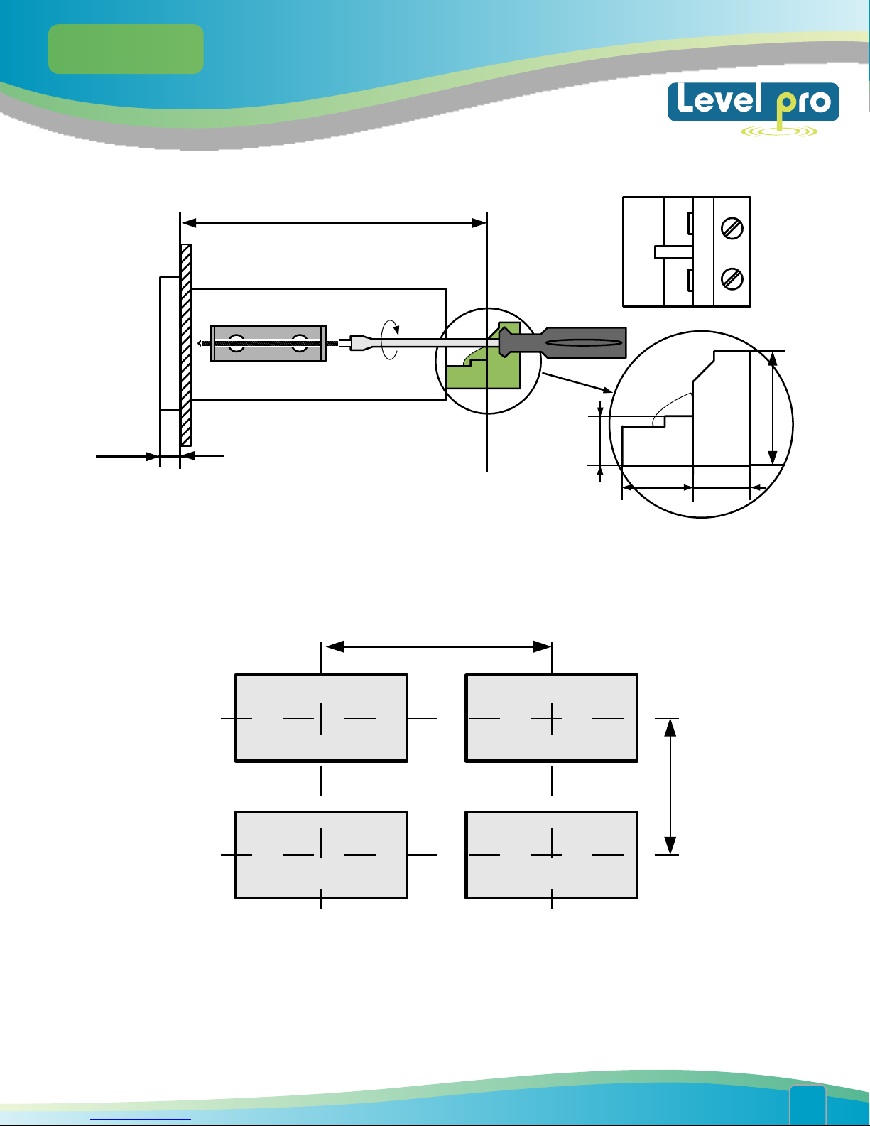
In order to install the unit, a 90.5 x 43 mm mounting hole (Figure 4.1, 4.2) must be prepared. The thickness of the
material of which the panel is made must not exceed 5mm. When preparing the mounting hole take the grooves
for catches located on both sides of the housing into consideration (Figure 4.1, 4.2). Place the unit in the
mounting hole inserting it from the front side of the panel, and then fix it using the brackets (Figure 4.3). The
minimum distances between the centre points of multiple
units - due to the thermal and mechanical conditions of operation - are 115 mm x 67mm (Figure 4.4).
90,5 mm
13 mm
8 mm
13 mm
1 mm
8 mm
1 mm
43 mm
max. 5 mm
Figure 4.1. Recommended mounting hole dimensions
92 mm
Figure 4.2. Allowable mounting hole dimensions
43 mm
max. 5 mm
www. levelprosales.com
www. levelprosales.com
06
ITC 450/470
User manual
5 mm
92 mm
8,5 mm
12 mm
16 mm
10 mm
Figure 4.3. Installing of brackets, and dimensions of connectors
115 mm
67 mm
Figure 4.4. Minimum distances when assembly of a number of units
www. levelprosales.com
www. levelprosales.com
07

ITC 450/470
User manual
4.3. CONNECTION METHOD
Installation should be conducted by qualified personnel . During installation all available safety
requirements should be considered. The fitter is responsible for executing the installation
according to this manual, local safety and EMC regulations.
The unit is not equipped with an internal fuse or power supply circuit breaker. Because of this
an external time-delay cut-out fuse with a small nominal current value must be used
(recommended bipolar, max. 2A) and a power supply circuitbreaker located near the unit. In
the case of using a monopolar fuse it must be mounted on the phase cable (L).
The power supply network cable diameter must be selected in such a way that in the case of a
short circuit of the cable from the side of the unit the cable shall be protected against
destruction with an electrical installation fuse.
Wiring must meet appropriate standards and local regulations and laws.
In order to secure against accidental short circuit the connection cables must be terminated
with appropriate insulated cable tips.
Tighten the clamping screws. The recommended tightening torque is 0.5 Nm. Loose screws can
cause fire or defective operation. Over tightening can lead to damaging the connections inside
the units and breaking the thread.
In
the case of the unit being fitted with separable clamps they should be inserted into
appropriate connectors in the unit, even if they are not used for any connections.
Unused terminals (marked as n.c.) must not be used for connecting any connecting cables
(e.g. as bridges), because this can cause damage to the equipment or electric shock.
If the unit is equipped with housing, covers and sealing to, protecting against water intrusion,
pay special attention to their correct tightening or clamping. In the case of any doubt consider
using additional preventive measures (covers, roofing, seals, etc.). Carelessly executed
assembly can increase the risk of electric shock.
After
the installation is completed do not touch the unit’s connections when it is switched on,
because it carries the risk of electrical shock.
Due to possible significant interference in industrial installations appropriate measures assuring correct
operation of the unit must be applied. To avoid the unit of improper indications keep recommendations
listed below.
www. levelprosales.com
www. levelprosales.com
08
ITC 450/470
User manual
Avoid running signal cables and transmission cables together with power supply cables and cables
controlling inductive loads (e.g. contactors). Such cables should cross at a right angle.
Contactor coils and inductive loads should be equipped with interference protection systems, e.g. RCtype.
Use of screened signal cables is recommended. Signal cable screens should be connected to the earthing
only at one of the ends of the screened cable.
In the case of magnetically induced interference the use of twisted pair of signal cables is recommended.
Twisted pair (best if shielded) must be used with RS-485 serial transmission connections.
In the case of measurement or control signals are longer than 30m or go outside of the building then
additional safety circuits are required.
In the case of interference from the power supply side the use of appropriate interference filters is
recommended. Bear in mind that the connection between the filter and the unit should be as short as
possible and the metal housing of the filter must be connected to the earth with the largest possible
surface. The cables connected to the filter output must not be run with cables with interference (e.g.
circuits controlling relays or contactors).
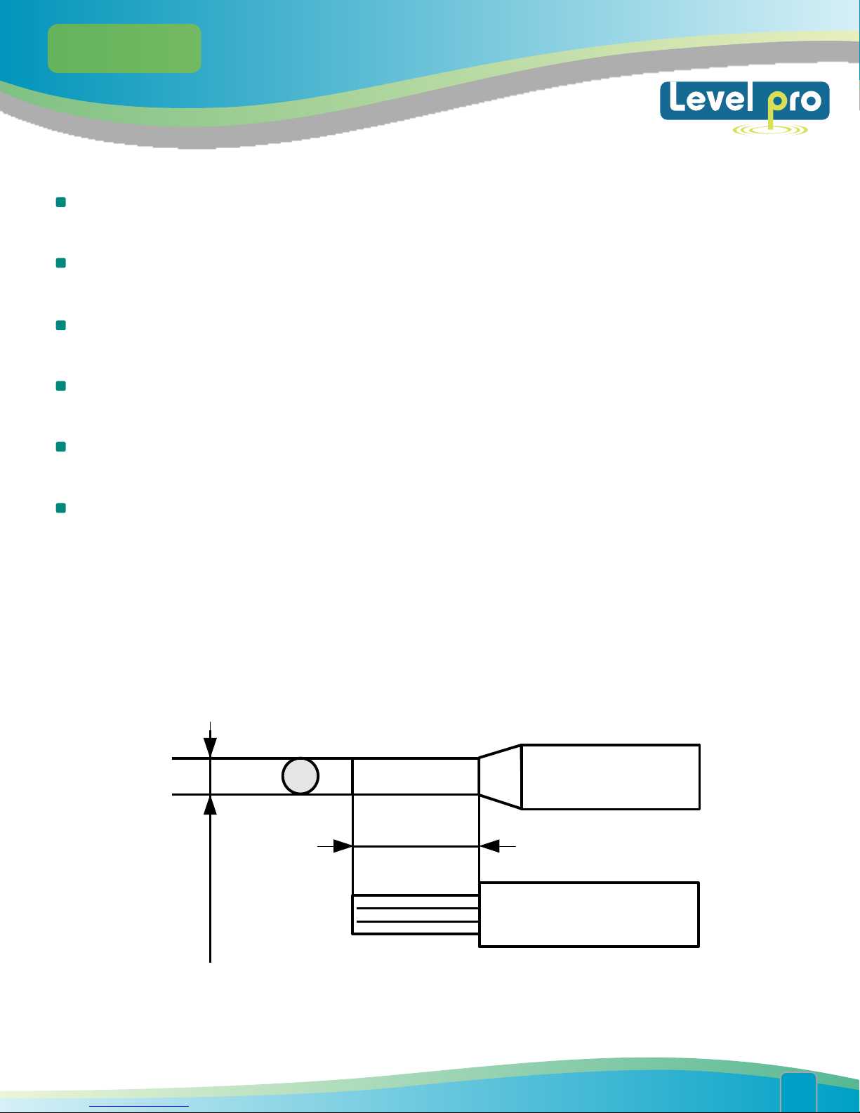
Connections of power supply voltage and measurement signals are executed using the screw connections
on the back of the unit’s housing.
6-7 mm
max. 2 mm
Figure 4.5. Method of cable insulation replacing and cable terminals
www. levelprosales.com
www. levelprosales.com
09
ITC 450/470
User manual
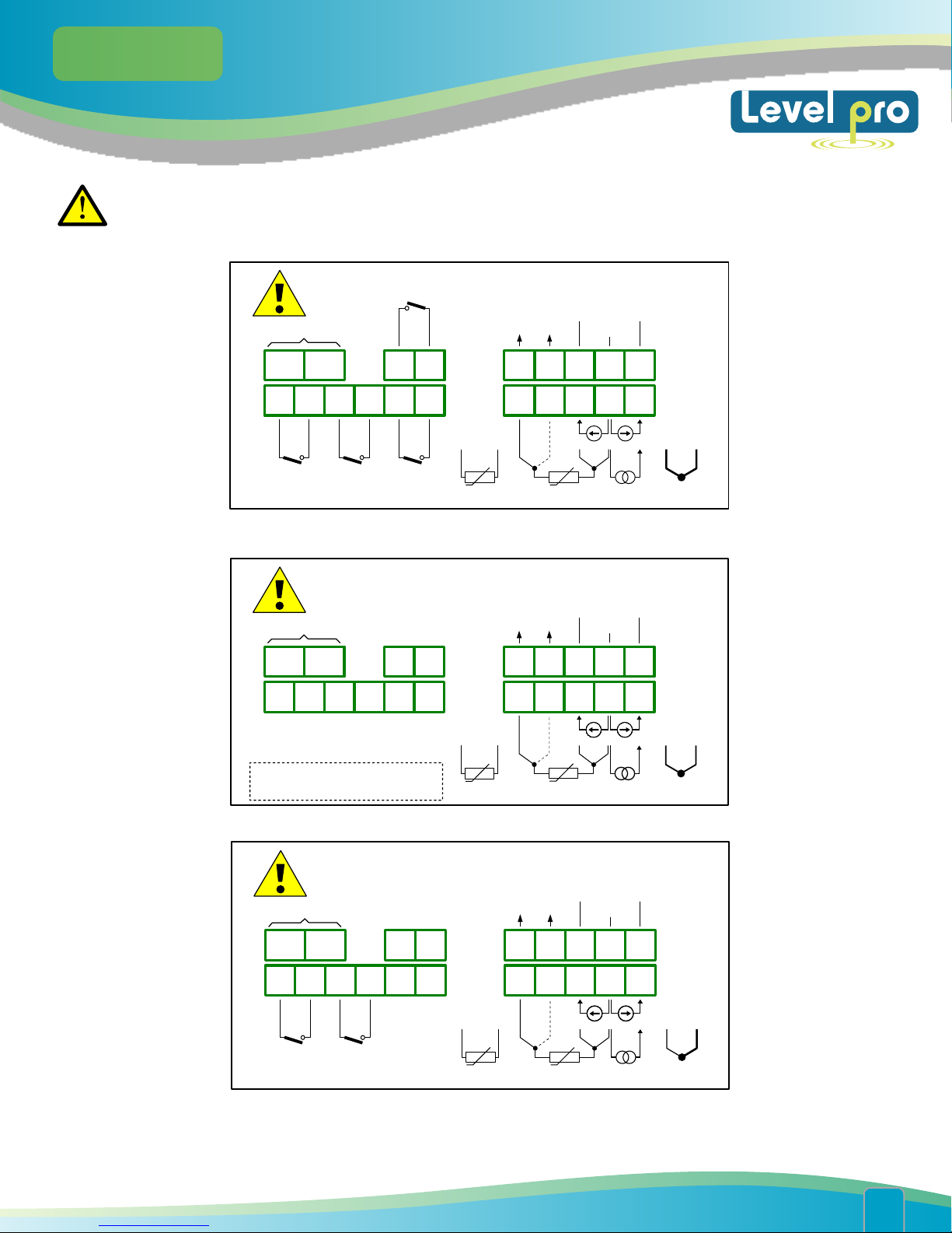
All connections must be made while power supply is disconnected !
Power
supply
(depending on version)
1 2 5 6 7 8 9
10 1 1 12 13 14 15
R1
(optional)R2(optional)
R4
(optional)
3 4
R3
(optional)
+24V +5%, -10%
Imax = 100mA
+
31 32 33 34 35
31 34
RTD
Uo
-
Figure 4.6. Terminals description (relay outputs)
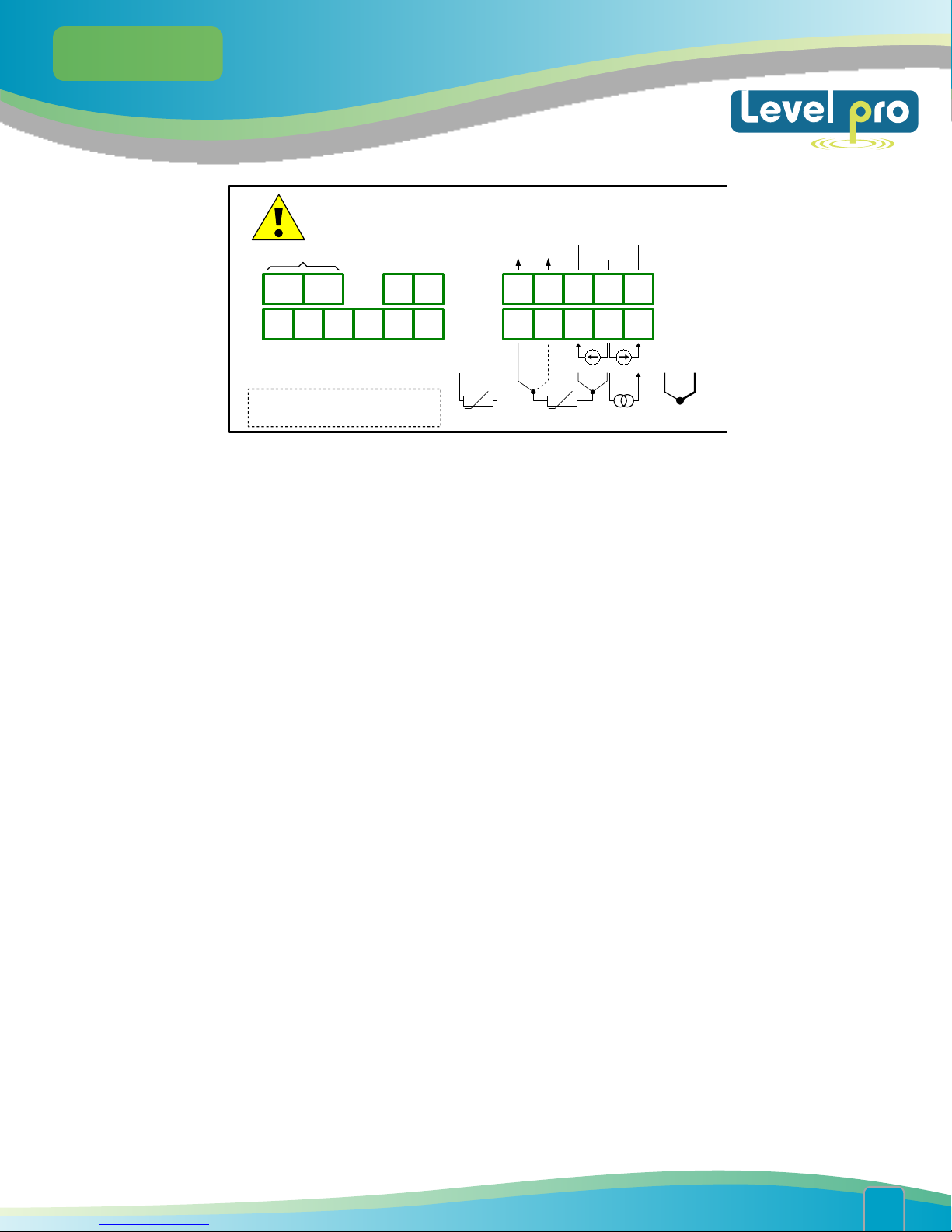
Power
supply
(depending on version)
1 2 5 6 7 8 9
(optional)
OC4
+ -
3 4
10 1 1 12 13 14 15
- + - + - +
OC1
(optional) (optional) (optional)
OC1 ÷ OC4: Umax = 30V DC,
Imax = 30mA, Pmax = 100mW
OC2
OC3
+24V +5%, -10%
Imax = 100mA
+
31 32 33 34 35
31 34
RTD
-
DATA-
;
+D
RTD
mA
RS - 485
GND DATA+
DATA
+
mV
RTD
mA
RS - 485
DATA+GND
;
D
+
V
33 34
+
TC
33 34
+
TC
-
-
Figure 4.7. Terminals description (OC-type outputs)
Power
supply
(depending on version)
1 2 5 6 7 8 9
10 1 1 12 13 14 15
R1
(optional) (optional)
Figure 4.8. Terminals description (relay and active current outputs)
R2
ACTIVE
current output
(optional)
- +
3 4
ALMLALML
+24V +5%, -10%
Imax = 100mA
+
31 32 33 34 35
31 32
RTD
GND DATA+
Uo
-
RTD
RS - 485
DATA
&
91
&
33 34
1
-
+
mA
TC
www. levelprosales.com
www. levelprosales.com
10
ITC 450/470
User manual
Power
supply
(depending on version)
ACTIVE
current output
(optional)
+24V +5%, -10%
Imax = 100mA
Uo
-
+
GND DATA+
DATA
RS- 485
- +
1 2 5 6 7 8 9
10 1 1 12 13 14 15
OC1
(opcja)
OC1 ÷ OC2: Umax = 30V DC,
Imax = 30mA, Pmax = 100mW
Figure 4.9. Terminals description (OC-type and active current outputs)
+
+
OC2
(opcja)
-
3 4
n.c. n.c.
31 34
RTD
31 32 33 34 35
+
RTD
mV
V
mA
+
33 34
+
TC
-
www. levelprosales.com
www. levelprosales.com
11

ITC 450/470
User manual
www. levelprosales.com
www. levelprosales.com
12

ITC 450/470
User manual
Temperature sensor can be connected to the device in typical 4-wire circuit (Figure 4.17a) or 3-wire circuit
(Figure 4.17b). Due to precision of measurement 4-wire circuit is recommended.
If 2 wire circuit is used, the resistance of wires should be as small as possible, to avoid of measurement
errors. Measured value can be corrected (constant correction) using „toFS” parameter from menu
„inPt”. Due to low precision 2-wire connection is not recommended.
When 4-wires or 2-wires connection is used, the resistance of particular wires (Ra ÷ Rd) CAN BE DIFFERENT.
When 3-wires connection is used, the resistance of particular wires (Ra ÷ Rd) MUST BE IDENTICAL to enable
proper compensation of it's resistance. The resistance of particular wire should not be greater than 20 .
a) b) c)
31 32 33 34
Ra
Rb Rc : Rd
RTD
Ra, Rb, Rc, Rd can be different
a) 4-wires circuit; b) 3-wires circuit; c) 2-wires circuit
31 32 33 34
n.c.
Ra Rc : Rd
RTD
Ra = Rc = Rd
Figure 4.17. Connection of RTD sensors:
31 32 33 34
n.c. n.c.
Ra Rc
RTD
Ra, Rc can be different
www. levelprosales.com
www. levelprosales.com
13

ITC 450/470
User manual
The connection circuit should not be changed while unit is powered. While using TC, RTD or voltage
inputs (0-150mV) the device is able to detect wire breaks. Wire breaks are detected within about 2
seconds. For connectors number 32 and 33 of RTD input it may take up to about 7 seconds. During
detection measurements will be incorrect. If wire break is detected "S.Err" (sensor error) message is
displayed.
Contacts of relay outputs are not equipped with spark suppressors. While use the relay outputs for
switching of inductive loads (coils, contactors, power relays, electromagnets, motors etc.) it is required to
use additional suppression circuit (typically capacitor 47nF/ min. 250VAC in series with 100R/5W resistor),
connected in parallel to relay terminals or (better) directly on the load. In consequence of using the
suppression circuit, the level of generated electromagnetic disturbances is lower, and the life of relay
contacts rises.
www. levelprosales.com
www. levelprosales.com
14

ITC 450/470
User manual
www. levelprosales.com
www. levelprosales.com
15
ITC 450/470
User manual
4.4. MAINTENANCE
The unit does not have any internal replaceable or adjustable components available to the user. Pay attention
to the ambient temperature in the room where the unit is operating. Excessively high temperatures cause
faster ageing of the internal components and shorten the fault-free time of the unit's operation.
In cases where the unit gets dirty do not clean with solvents. For cleaning use warm water with small amount
of detergent or in the case of more significant contamination ethyl or isopropyl alcohol.
Using any other agents can cause permanent damage to the housing.
Product marked with this symbol should not be placed in municipal waste. Please check local
regulations for disposal and electronic products.
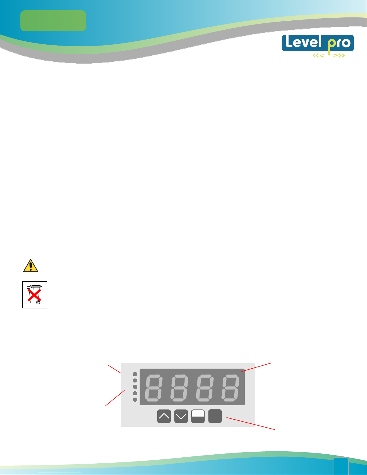
5. FRONT PANEL DESCRIPTION
alarm LED indicator (AL)
Thresholds exceeding
LED indicators (R)
AL
R1
R2
R3
R4
$$
ESC
MENU
ENTER
display
programming
pushbuttons
www. levelprosales.com
www. levelprosales.com
16
 Loading...