

Page 1

Operating Manual
Sensors
1. General information
www.levelprosales.com
1.1 Information on the operating manual
This operating manual contains important information on proper usage of the device. Read this
operating manual carefully before installing and starting up the pressure measuring device.
Adhere to the safety notes and operating instructions which are given in the operating manual.
Additionally applicable regulations regarding occupational safety, accident prevention as well as
national installation standards and engineering rules must be compiled with.
This operating manual is copyrighted. The contents of this operating manual reflect the version
available at the time of printing. It has been issued to our best knowledge. However, errors may have
occurred. Levelpro is not liable for any incorrect statements and their effects.
1.2 Symbols used
DANGER! – dangerous situation, which may result in death or serious injuries
WARNING! – potentially dangerous situation, which may result in death or serious injuries
CAUTION! – potentially dangerous situation, which may result in minor injuries
CAUTION! – potentially dangerous situation, which may result in physical damage
NOTE – tips and information to ensure a failure-free operation
1.3 Target group
WARNING! To avoid operator hazards and damages of the device, the following instructions
have to be worked out by qualified technical personnel.
1.4 Limitation of liability
-Technical modifications reserved-
By non-observance of the operating manual, inappropriate use, modification or damage, no
liability is assumed and warranty claims will be excluded.
www.levelprosales.com
Page 2
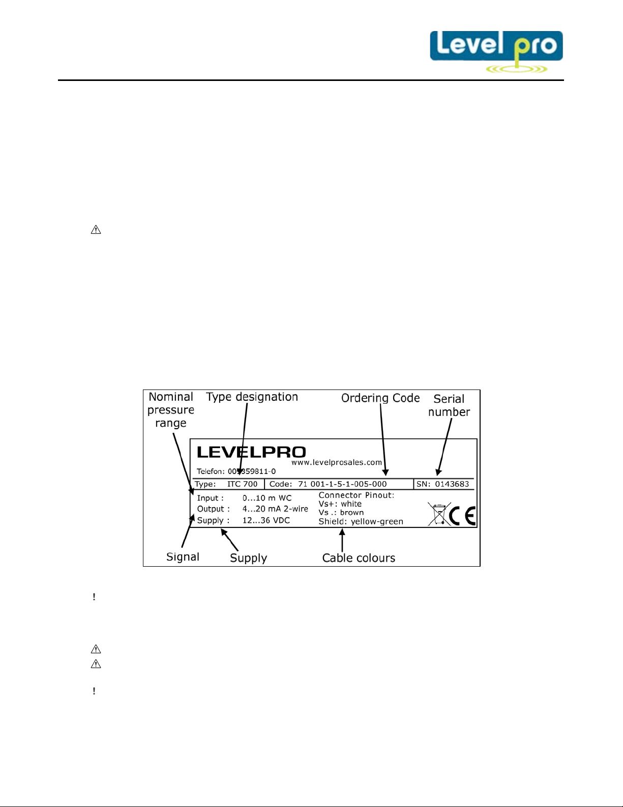
Fig. 1 manufacturing label
1.5 Intended use
− The probes have been developed for continuous level measurement. It is the operator’s
responsibility to check and verify the suitability of the device for the intended application. If
any doubts remain, please contact our sales department in order to ensure proper usage.
Levelpro is not liable for any incorrect selections and their effects!
− Permissible media are gases or liquids (no solids and frozen media), specified in the data
sheet. In addition it has to be ensure, that this medium is compatible with the media wetted
parts.
− The technical data listed in the current data sheet are engaging and must be complied with.
− If the data sheet is not available, please order or download it from our homepage.
(www.levelprosales.com)
WARNING! – Danger through improper usage!
1.6 Package contents
Please verify that all listed parts are undamaged included in the delivery and check for consistency
specified in your order:
− probe
− mounting instructions
− with option SIL2 version:
Functional Safety Manual, Functional Safety Data Sheet, SIL Declaration of Conformity
2. Product Identification
The device can be identified by its manufacturing label. It provides the most important data. By
the ordering code the product can be clearly identified.
The manufacturing label must not be removed from the device!
3. Mechanical Installation
3.1 Mounting and safety instructions
WARNING! Install the device only when depressurized and currentless!
WARNING! This device may only be installed by qualified technical personnel who has read
and understood the operating manual!
Handle this h igh-sensitive electronic precision measuring device with care, both in packed and
unpacked condition!
www.levelprosales.com
Page 3

There are no modifications/changes to be made on the device.
Do not throw the package/device!
To avoid damaging the diaphragm, remove packaging and protective cap directly before
starting assembly. The delivered protective cap has to be stored
Place the protective cap on the pressure port again immediately after disassembling.
Handle the unprotected diaphragm very carefully – it is very sensitive and may be easily
damaged.
Do not use any force when installing the device to prevent damage of the device and the
plant!
When placing the device into operation or after maintenance work, the probe has to be
submerged slowly into the medium! A rough immersion into the medium can damage or
destroy the diaphragm.
If there is any danger of damage by lightning or overpressure when the device is installed
outdoor, we suggest putting a sufficiently dimensioned overpressure protection between the
supply or switch cabinet and the device.
3.2 Installation steps for probe
− Carefully remove the pressure measuring device from the package and dispose of the package
properly.
− Mount the device according to your demands.
Usually, the probe has been delivered without mounting accessories. For different mounting
demands, Levelpro offers as accessories mounting clamps, terminal clamps and mounting
flanges.
3.3 Installation steps for flange version
(LMK 382 / LMK 382 H)
− Carefully remove the pressure measuring device from the package and dispose of the package
properly.
− Please ensure that the mounting thread is clean and free of damage.
− Check to ensure that the O-ring fits properly in t he groove.
− Screw in the mounting thread of the transmitter in the transmitter flange.
− Next, tighten it by an op en-end wrench, (approx… 25 Nm)
− Install the flange according to your demands.
If a new transmitter flange is needed, it can be ordered from Levelpro.
3.4 Removing the protecting cap (if existing)
For the protection of the diaphragm, some of the probes have a plugged-on protection cap. If the
device shall be used in high-viscosity media such as sludge, a removal of the cap before start-up
is necessary. Thus, the sensor becomes flush and the medium will attain quickly to the diaphragm.
If it is necessary for your application to remove the protection cap, this has to be done with
utmost care. To prevent a damage of the diaphragm, please follow these instructions.
Removal by hand
− Hold the probe in a way that the protection cap points upwards.
− Hold the probe with one hand on the sensor section (1).
− Remove the protection cap (2) with the other hand.
www.levelprosales.com
Page 4
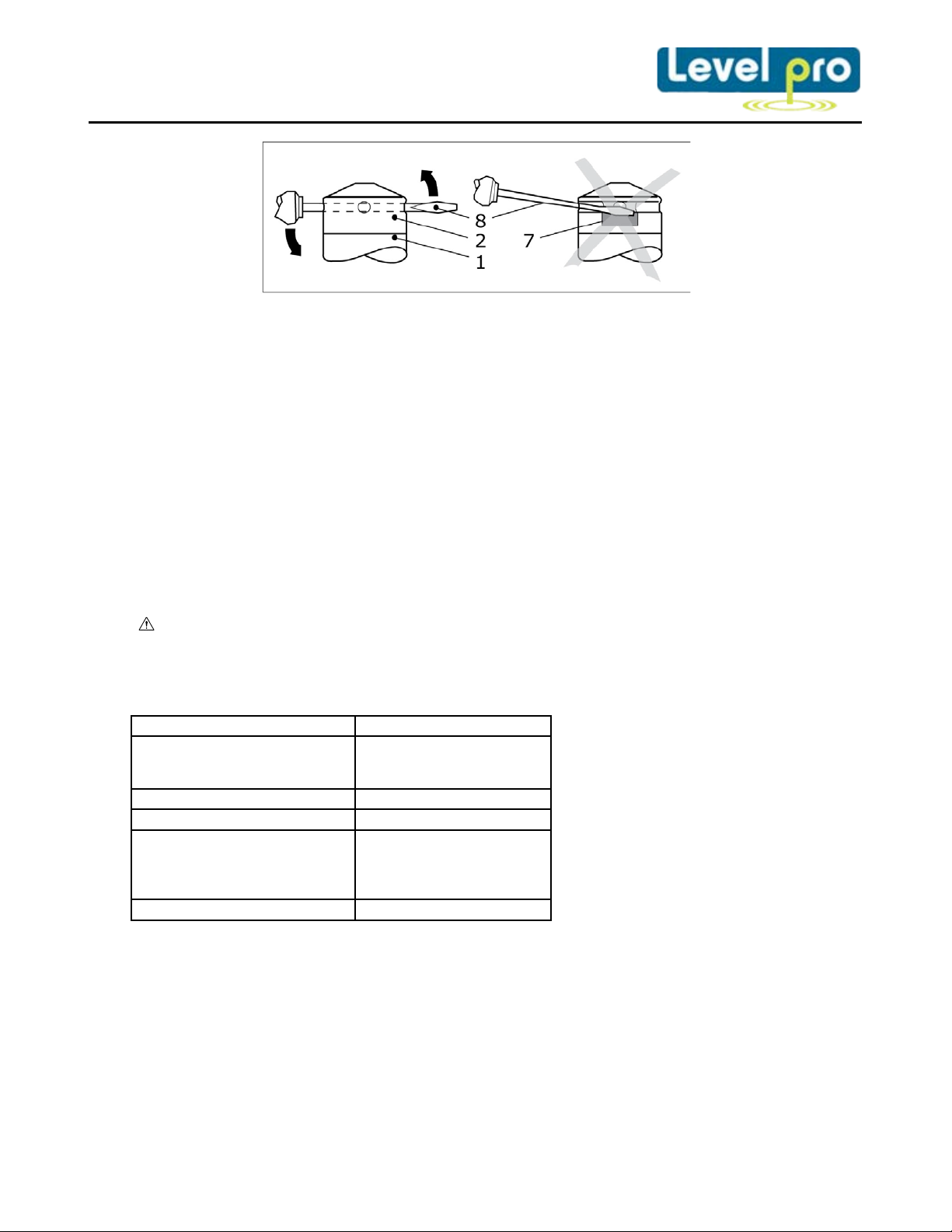
Fig. 2 removal of protection cap
Suppy +
Signal + (on ly 3-wire)
wh (white)
gn (green)
LMK 307T and LMP 037T
cable colours
Supply P+
Supply T-
wh (white)
pn (pink)
Shield
gn/ye (yellow / green)
− Hold the probe in a way that the protection cap points upwards.
− Slide a small tool such as a screwdriver (8) straight through two opposite drill holes in the
protective cap (2)
− Lever it off by moving up the handle of the screwdriver.
Make sure that the sensor (7) under the protection cap will not be damaged!
3.5 Cable protection (optional)
On order, the probe has been delivered with cable protection; if the device has optionally been
prepared for mounting with stainless steel or PVC pipe, a suitable cable protection has to be
mounted by the customer.
The probe must be installed in such a way that rubbing or impact of the device, e.g. against a
tank wall, is prevented, it is also important to consider the operating conditions such as flow
conditions.
4. Electrical Installation
WARNING! Install the device only when currentless!
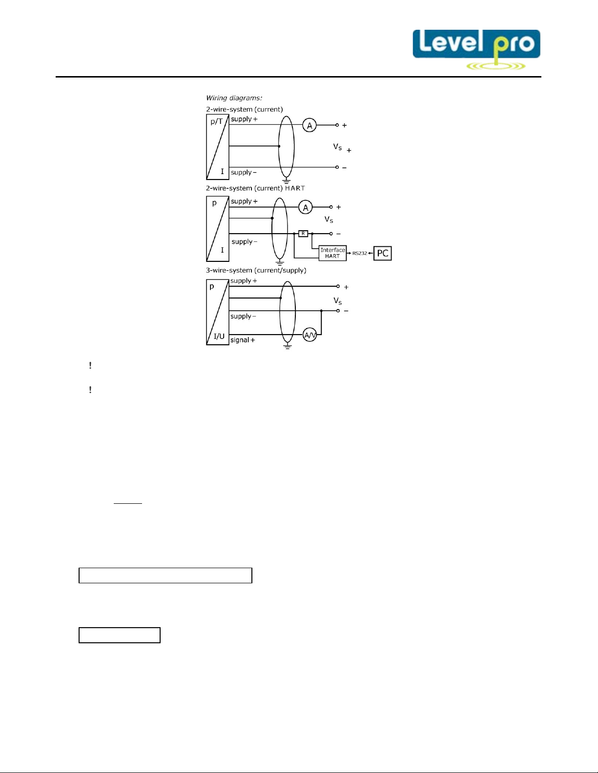
Establish the electrical connection of the device according to the technical data shown on the
manufacturing label, the following table and the wiring diagram.
Pin configuration:
Electrical connections Cable colours
Supply –
Shield gn/ye (green / yellow)
Suppy P-
Supply T+
bn (brown)
bn (brown)
gr (gray)
www.levelprosales.com
Page 5
A minimum static bending radius has to be complied with. For static installation use the 10-
fold cable diameter, for dynamic applications use the 20-fold diameter.
Prevent the damage or removal of the PTFE filter which is fixed over the end of the air tube on
devices with cable outlet and integrated air tube.
For the electrical connection a shielded and twisted multicore cable is recommended.
If a transition is desired from a probe cable w ith gauge tube to a cable without gauge tube, we
recommend our terminal box KL 1 or KL 2.
Usually, the required cable is included in the scope of delivery. If it is although necessary to
connect an existing or special cable, the total resistance will increase. For application, where
this additional resistance of the connecting cable could cause problems, this cable has to be
checked with the following calculation.
2
=
with RL: resistance of connecting cable in
V
= (RL1 + RL2 + … + R
tot
with V
: specific resistant in mm
l: cable length in m
A: cross section of conductor in mm
)· 0.02 A
load
: total voltage drop
tot
R
: load resistance (to be taken out of the current data sheet)
load
2
/m
2
the following condition has to be fulfilled:
Vs > V
tot
+ V
s min
with Vs: planned s upply voltag e
V
s min:
minimal supply voltage (to be taken out of the current data sheet)
www.levelprosales.com
Page 6
5. Characteristic
Disassembly
Assembly
5.1 HART communication (in H-devices)
The analogue output signal is overridden by an additional signal according to the HART –
specification. The device can be configured via a HART – communication device. Therefore we
suggest our programming kit CIS 155 (available as accessory). It consists of HART –modem,
connecting cables as well as configuration of all parameters. (The software is compatible will all
Windows – systems from Windows 98 and higher.)
To ensure a trouble-free operating the following requirements should be fulfilled:
Maximal cable length between device and power supply:
65 10
=
whereas L
max
R
: resistance of the cable together with
v
40 10
: maximum length of cable in [m]
the load resistance in []
C
: capacity of the cable in [pF/m]
v
resistance R:
12
=
0.024
whereas U: power supply in [VDC]
The resistance must be at least 240 .
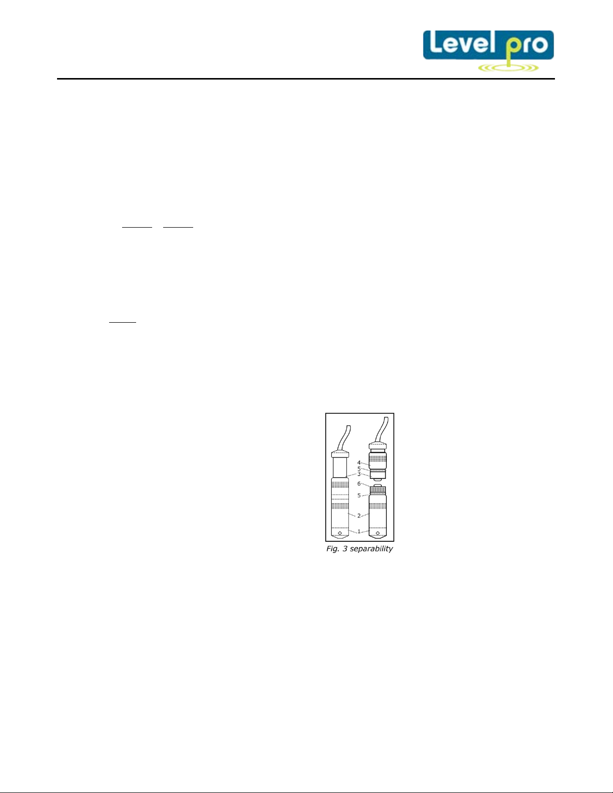
5.2 Separable probes
In order to facilitate stock keeping and maintenance, the probe head is plugged to the cable
assembly with a connector and can be easily changed.
− Hold the probe on the sensor section
− While screwing and pulling of the sensor
− Check the o-rings (5,6) and exchange damaged o-rings if necessary.
− Lubricate the radial o-rings (5) wit h Vaseline or o-ring grease.
− Remove any grease residue from the axial o-ring (6).
− Plug the cable section (3) straight into the plug of the sensor section (2)
− Hold the probe onto the sensor section (2) with one hand. Screw on and tighten the nut (4)
(2) with one hand and turn the nut (4)
carefully to the left with the other hand.
Prevent torsion of the cable section (3)
against the housing!
section (2) from the cable section (3),
hold it straight to prevent damages on
the plugs.
carefully with the other hand. Prevent torsion of the cable section (3) against the housing!
www.levelprosales.com
Page 7
Pin configuration
Electrical
connections
Binder series 723
(5-pin)
Binder series 723
(7-pin)
2-wire system
Supply +
Supply -
3 1 3
1
3-wire system
Supply +
3
3
Shield
5
2
Communication interface
RxD
-
4
5.3 Accuracy 0.1 % FSO
Shield 5 2
Supply –
Signal +
Devices with an accuracy of 0.1 % FSO have micro-controlled electronics for processing and
improving th e signal. As a matter of principle, the processing takes more time than for analogue
sensors, which have only an amplifier. Due to this longer response time, the output signal follows
the measured value discontinuously. For relatively stable measuring values, this characteristic is
secondary. Please compare the specification for the response time in the data sheet.
5.4 Communication interface (i-devices)
Intelligent devices with an optional communication interface can also be configured with these
electronics. Offset, span and damping are programmable within the limits given in the data sheet.
For configuration, the programming kit CIS 155 consisting of Adapt 1, power supply and Windows
compatible programming software is necessary. This can be ordered as accessory from Levelpro.
6. Initial start-up
WARNING! Before s tart-up, the user has to check for proper installation and for any visible
defects.
WARNING! The device can be started and operated by authorized personnel only, who have
read and understood the operating manual!
WARNING! The device has to be used within the technical specifications, only (compare the
data in the data sheet)!
TxD
GND
4
1
-
-
1
6
5
7
7. Placing out of service
WARNING! When dismantling the device, it must always be done in the depressurized and
currentless condition! Check also if the medium has to be drained off before dismantling!
WARNING! Depending on the medium, it may cause danger for the user. Comply therefore
with adequate precautions for purification.
www.levelprosales.com
Page 8

8. Maintenance
electronic equipment may not be disposed by domestic refuse!
In principle , this device is maintenance-free. If desired, the housing of the device can be cleaned
when switched off using a damp cloth and non-aggressive cleaning solutions.
Depending on the measuring medium, however, the diaphragm may be polluted or coated with
deposit. If the medium is known for such tendencies, the user has to set appropriate cleaning
intervals. After placing the device out of service correctly, the diaphragm can usually be cleaned
carefully with a non-aggressive cleaning solution and a soft brush or sponge. If the diaphragm is
calcified, it is recommended to send the device to Levelpro for decalcification. Please read
therefore chapter “Service / Repair” below.
An incorrect cleaning can cause irreparable damages on the diaphragm. Never use spiky
objects or pressured air for cleaning the diaphragm.
9. Service / Repair
9.1 Recalibration
During the life-time of a probe, the value of offset and span may shift. As a consequence, a
deviating signal value in reference to the nominal pressure range starting point or end point may
be transmitted. If one of these two phenomena occurs after prolonged use, a recalibration is
recommended to ensure furthermore high accuracy.
9.2 Return
Before every return of your device, whether for recalibration, decalcification, modifications or
repair, it is necessary to contact us to ensure a fast handling of your request. It is necessary to
contact us to ensure a fast handling of your request. Please inform us by calling us at: 1-855-
879-4266 include the number of devices sent and request a RMA. Then clean the device and pack
it shatterproof before send it to Levelpro indicating the RMA.
10. Disposal
The device must be disposed according to the European Directives 2002/96/EG and
2003/108/EG (on waste electrical and electronic equipment) Waste of electrical and
11. Warranty conditions
The warranty conditions are subject to the legal warranty period of 24 months from the date of
delivery. In case of improper use, modifications of or damages to the device, we do not accept
warranty claims. Damaged diaphragms will also not be accepted. Furthermore, defects due to
normal wear are not subject to warranty services.
WARNING! Depending on the measuring medium, deposit on the device may cause danger for
the user and the environment. Comply with adequate precautions for purification and dispose
of it properly.
www.levelprosales.com
 Loading...