

Page 1

1
V1.0_20161125
LevelOne
User Manual
WRE-8011E
AC1200 Wireless Range Extender
Page 2

2
Table of Contents
1 Introduction ............................................................ 5
2 Getting to know the device ................................... 7
Features .................................................................................. 5
Device Requirements ............................................................. 5
Using this Document .............................................................. 6
Notational conventions ................................................... 6
Typographical conventions ............................................ 6
Special messages .......................................................... 6
Getting Support ....................................................................... 6
Computer / System requirements .......................................... 7
Package Contents .................................................................. 7
LED meanings & activations .................................................. 7
Top Side .......................................................................... 7
Rear and Left Panel and bottom Side ........................... 8
3 Computer configurations under
different OS, to obtain IP address
automatically ......................................................... 9
For Windows 98SE / ME / 2000 / XP .................................... 9
For Windows Vista-32/64 ..................................................... 12
For Windows 7-32/64 ........................................................... 15
For Windows 8/8.1-32/64 ..................................................... 19
For Windows 10-32/64 ......................................................... 24
4 Connecting your device ...................................... 28
Connecting the Hardware .................................................... 28
WPS Pairing between WRE-8011E and
Wireless xDSL/Cable Modem ........................................... 29
5 Advanced Configuration ..................................... 30
Advanced Configuration ....................................................... 30
Repeater Mode (Extend your Wireless Network)
............................................................................................. 30
AP Mode (Extend your Wired Network to allow
wireless devices to connect your wired
network using Wi-Fi) .......................................................... 31
Wireless Connection ............................................................. 32
6 What the Internet/WAN access of your
own Network now is ............................................ 34
Internet/WAN access is the DHCP client ............................ 36
Internet/WAN access is the Static IP ................................... 37
Internet/WAN access is the PPPoE client........................... 39
Page 3

3
7 Getting Started with the Web pages .................. 40
Accessing the Web pages ................................................... 40
Testing your Setup ................................................................ 41
Default device settings ......................................................... 41
8 Quick Setup ......................................................... 43
Repeater Mode (Extend your Wireless Network)
............................................................................................. 44
AP Mode (Extend your Wired Network to allow
wireless devices to connect your wired
network using Wi-Fi) .......................................................... 45
9 LAN Interface ...................................................... 47
LAN Interface Setup ............................................................. 47
Changing the LAN IP address and subnet
mask .................................................................................... 49
DHCP Static IP Configuration .............................................. 52
10 Wireless Network - 5GHz ................................... 54
Wireless Basics ..................................................................... 54
Advanced Settings ................................................................ 57
Security .................................................................................. 59
WEP + Encryption Key ................................................. 61
WEP + Use 802.1x Authentication .............................. 62
WPA2/WPA Mixed + Personal (Pre-
Shared Key)............................................................... 63
WPA2/WPA Mixed + Enterprise (RADIUS) ................ 64
Wireless Access Control Mode ............................................ 66
Allow Listed ................................................................... 67
Deny Listed ................................................................... 68
WPS ....................................................................................... 69
11 Wireless Network – 2.4GHz ............................... 71
Wireless Basics ..................................................................... 71
Advanced Settings ................................................................ 74
Security .................................................................................. 76
WEP + Encryption Key ................................................. 78
WEP + Use 802.1x Authentication .............................. 80
WPA2/WPA Mixed + Personal (Pre-
Shared Key)............................................................... 81
WPA2/WPA Mixed + Enterprise (RADIUS) ................ 82
Wireless Access Control Mode ............................................ 84
Allow Listed ................................................................... 85
Deny Listed ................................................................... 85
WPS ....................................................................................... 87
Page 4

4
12 Status .................................................................. 89
13 Statistics .............................................................. 90
14 Firmware Upgrade .............................................. 91
About firmware versions ....................................................... 91
Manually updating firmware ................................................. 91
15 Backup/Restore Settings .................................... 93
Save Settings to File ............................................................. 93
Load Settings from File......................................................... 94
Resetting to Defaults ............................................................ 95
16 Password............................................................. 97
A Configuring your Computers .............................. 98
Configuring Ethernet PCs .................................................... 98
Before you begin ........................................................... 98
Windows® XP PCs ...................................................... 98
Windows 2000 PCs ...................................................... 98
Windows Me PCs ....................................................... 100
Windows 95, 98 PCs .................................................. 100
Windows NT 4.0 workstations ................................... 101
Assigning static Internet information to
your PCs .................................................................. 102
B IP Addresses, Network Masks, and
Subnets ............................................................. 103
IP Addresses ....................................................................... 103
Structure of an IP address ......................................... 103
Network classes .......................................................... 103
Subnet masks ..................................................................... 104
C UPnP Control Point Software on
Windows ME/XP ............................................... 106
UPnP Control Point Software on Windows ME ................ 106
UPnP Control Point Software on Windows XP
with Firewall ...................................................................... 107
SSDP requirements .................................................... 107
D Troubleshooting ................................................ 110
Troubleshooting Suggestions ............................................ 110
Diagnosing Problem using IP Utilities ............................... 112
ping .............................................................................. 112
nslookup ...................................................................... 113
E LICENSE STATEMENT / GPL CODE
STATEMENT .................................................... 114
Page 5

5
1 Introduction
Congratulations on becoming the owner of the Portable
Repeater. You will now be able to access the Internet using
your high-speed xDSL/Cable modem connection.
This User Guide will show you how to connect your Portable
Repeater, and how to customize its configuration to get the
most out of your new product.
Features
The list below contains the main features of the device and may
be useful to users with knowledge of networking protocols. If
you are not an experienced user, the chapters throughout this
guide will provide you with enough information to get the most
out of your device.
Features include:
10/100Base-T Ethernet router to provide Internet
connectivity to all computers on your LAN
User-friendly configuration program accessed via a web
browser
The Portable Repeater has the internal Ethernet switch
allows for a direct connection to a 10/100BASE-T Ethernet
network via an RJ-45 interface, with LAN connectivity for
both the Portable Repeater and a co-located PC or other
Ethernet-based device.
Device Requirements
In order to use the Portable Repeater, you must have the
following:
One RJ-45 Broadband Internet connection via cable
modem or xDSL modem
Instructions from your ISP on what type of Internet access
you will be using, and the addresses needed to set up access
One or more computers each containing an Ethernet card
(10Base-T/100Base-T network interface card (NIC))
TCP/IP protocol for each PC
For system configuration using the supplied
a. web-based program: a web browser such as Internet
Explorer v4 or later, or Netscape v4 or later. Note that
version 4 of each browser is the minimum version
requirement – for optimum display quality, use Internet
Explorer v5, or Netscape v6.1
Page 6
6
Note
You do not need to use a hub or switch in order to connect more
than one Ethernet PC to your device. Instead, you can connect
up to four Ethernet PCs directly to your device using the ports
labeled Ethernet on the rear panel.
Note
Provides clarifying or non-essential information on the current
topic.
Definition
Explains terms or acronyms that may be unfamiliar to many
readers. These terms are also included in the Glossary.
WARNING
Provides messages of high importance, including messages
relating to personal safety or system integrity.
Using this Document
Notational conventions
Acronyms are defined the first time they appear in the text
and also in the glossary.
For brevity, the Portable Repeater is referred to as “the device”.
The term LAN refers to a group of Ethernet-connected
computers at one site.
Typographical conventions
Italic text is used for items you select from menus and drop-
down lists and the names of displayed web pages.
Bold text is used for text strings that you type when prompted
by the program, and to emphasize important points.
Special messages
This document uses the following icons to draw your attention to
specific instructions or explanations.
Getting Support
Supplied by:
Helpdesk Number:
Website:
Page 7

7
2 Getting to know the device
Computer / System requirements
Windows 98SE, Windows Me, Windows 2000, Windows
XP, Windows Vista, Windows 7, Windows 8, Windows 8.1
and Windows 10.
Package Contents
1. WRE-8011E
2. Quick Installation Guide
3. Ethernet Cable (RJ-45)
LED meanings & activations
Top Side
The Top Side contains lights called Light Emitting Diodes (LEDs)
that indicate the status of the unit.
Figure 1: Top Side and LEDs
Page 8

8
Label
Color
Function
Wifi Signal
Green
On Wireless Signal Strength
Off: No WLAN link
Wireless
Green
On: WLAN link established and active
Blink: Valid Wireless packet being transferred
WPS
Green
Off: WPS link isn’t established and active
Blink: Valid WPS packet being transferred
Ethernet
Green
On: LAN link established and active
Off: No LAN link
Blink: Valid Ethernet packet being transferred
Label
Function
Ethernet
Connects the device via LAN Ethernet to a PC
WPS / RESET
WPS
Press this button for 3 full seconds and the
WPS LED will flash to start WPS.
Now go to the wireless adapter or device and
press its WPS button. Make sure to press the
button within 120 seconds (2 minutes) after
pressing the router's WPS button.
RESET
Reset button. RESET the WRE-8011E to its default
settings.
Press this button for at least 10 full seconds to RESET
device to its default settings.
Rear and Left Panel and bottom Side
The rear and right panel and bottom side contains a Restore
Defaults button, the ports for the unit's data and power
connections.
Page 9
9
3 Computer configurations under different OS,
to obtain IP address automatically
Before starting the WRE-8011E configuration, please kindly
configure the PC computer as below, to have automatic IP
address / DNS Server.
For Windows 98SE / ME / 2000 / XP
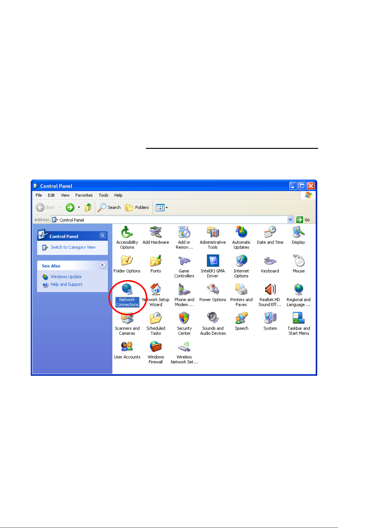
1. Click on "Start" -> "Control Panel" (in Classic View). In
the Control Panel, double click on "Network Connections"
to continue.
Page 10
10
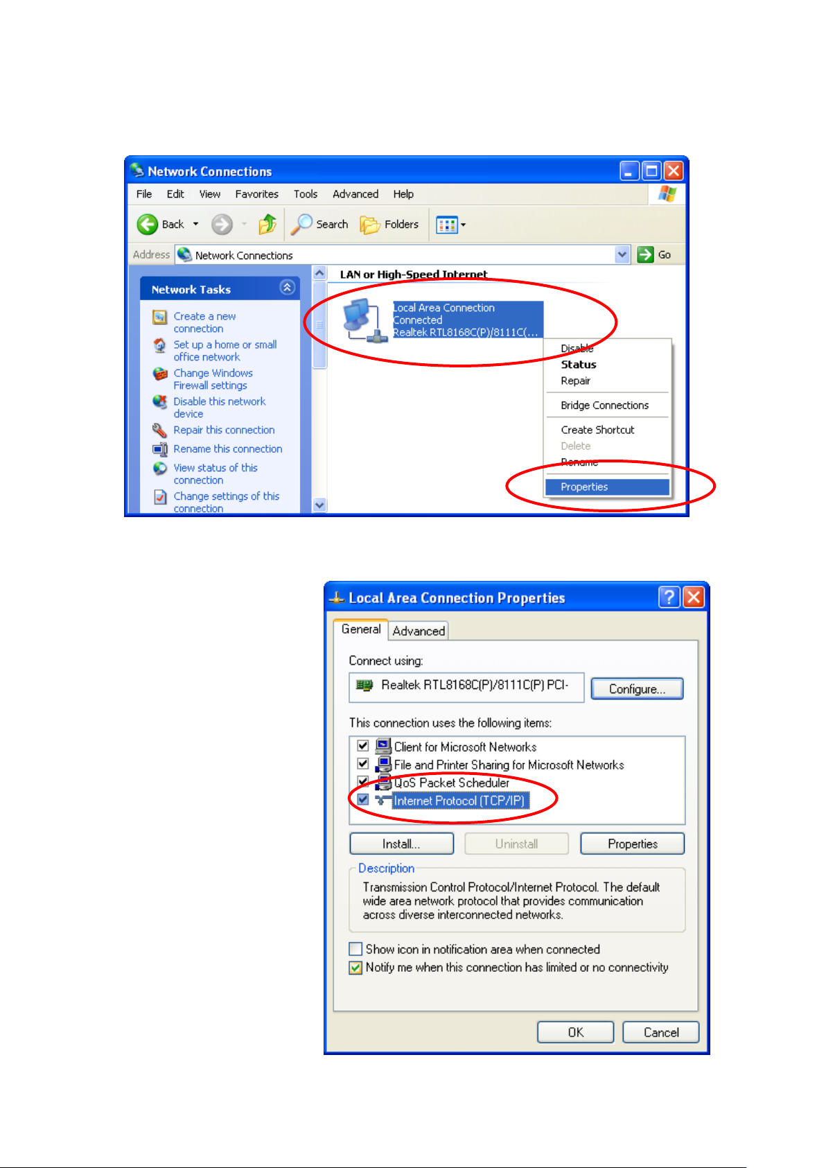
2. Single RIGHT click on "Local Area connection", then click
"Properties".
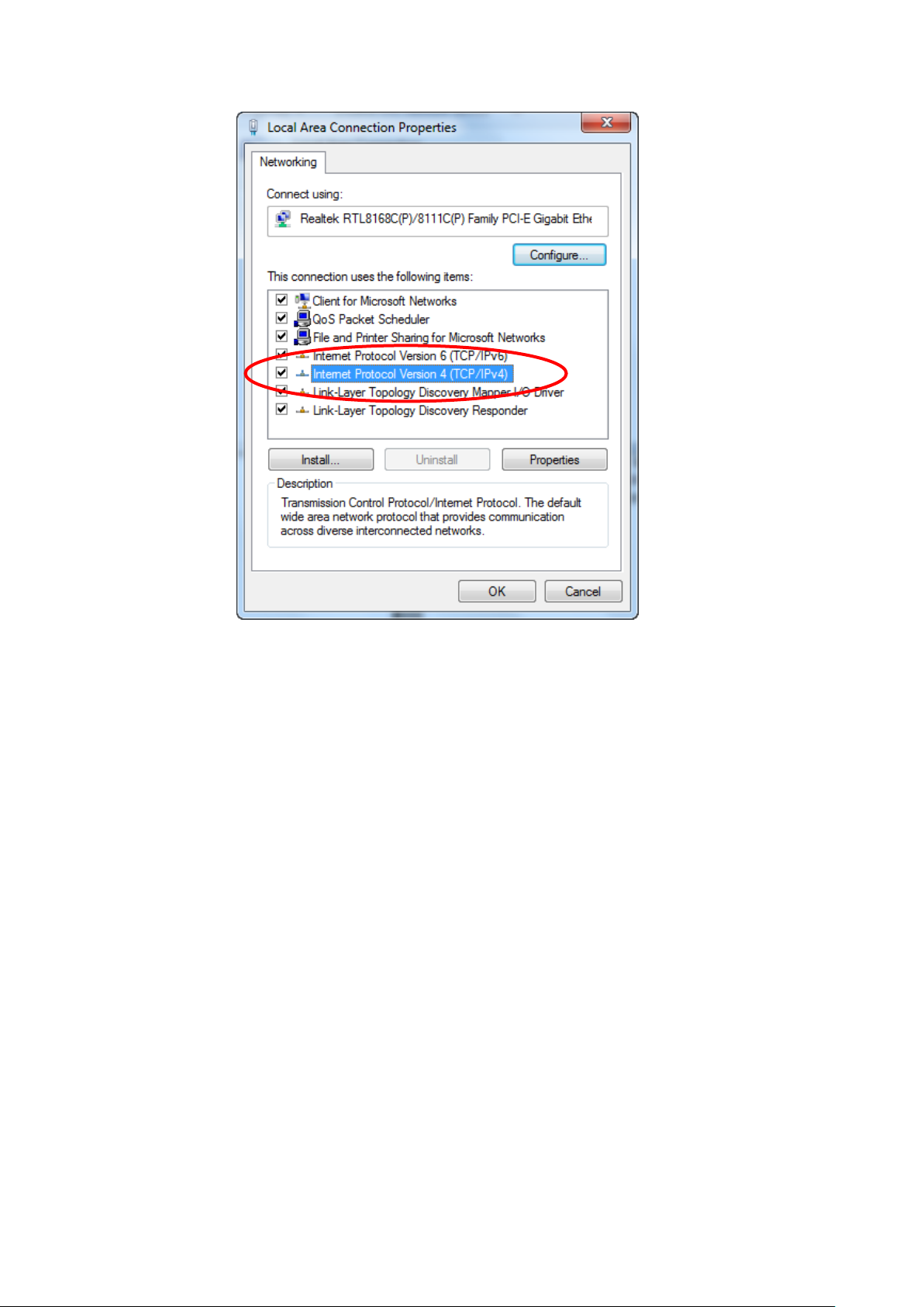
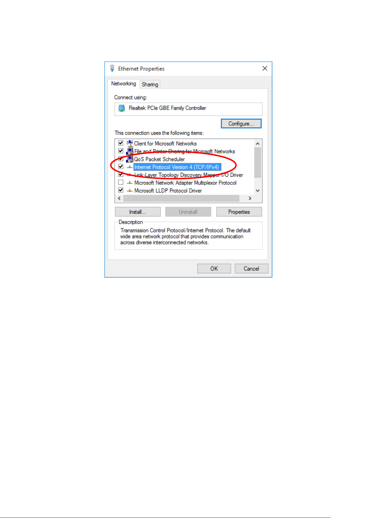
3. Double click on "Internet Protocol (TCP/IP)".
Page 11
11
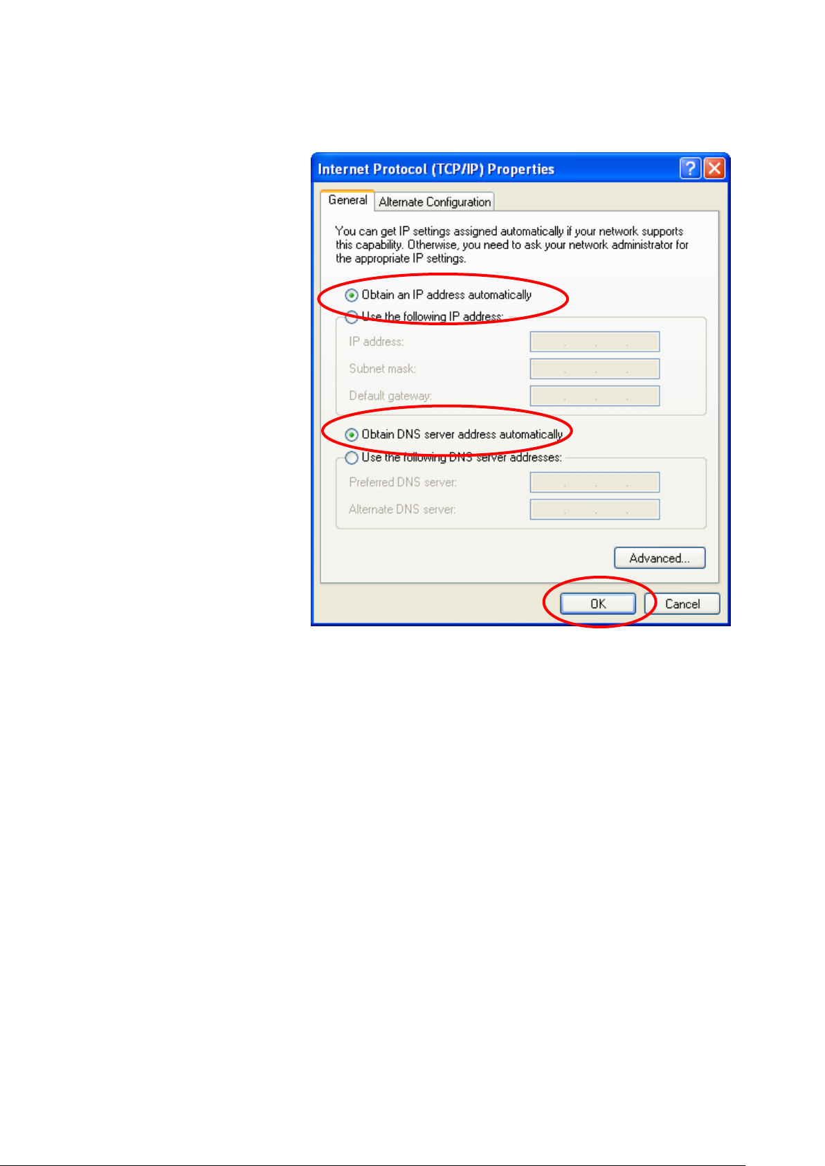
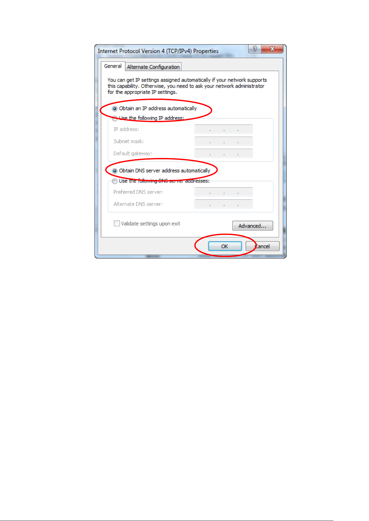
4. Check "Obtain an IP address automatically" and "Obtain
DNS server address automatically" then click on "OK" to
continue.
5. Click "Show icon in notification area when connected"
(see screen image in 3. above) then Click on "OK" to
complete the setup procedures.
Page 12
12
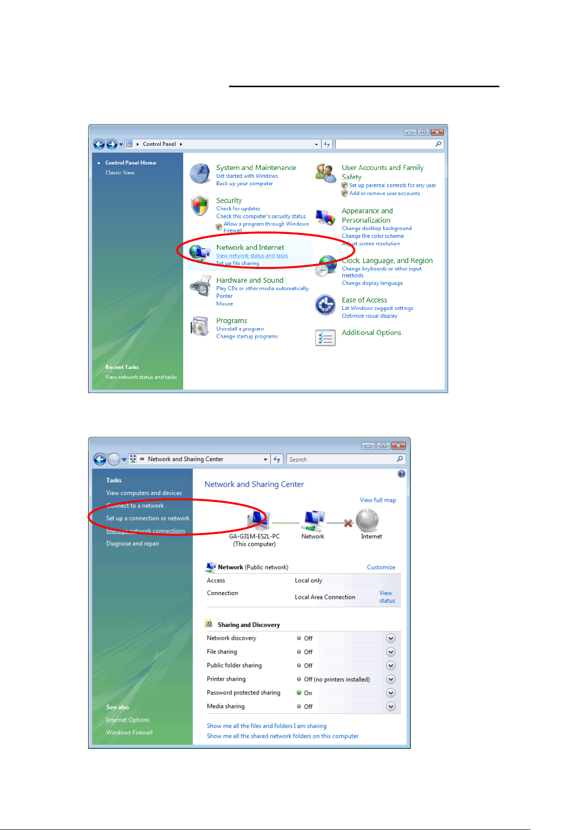
For Windows Vista-32/64
1. Click on “Start” -> “Control Panel” -> “View network
status and tasks”.
2. In the Manage network connections, click on “Manage
network connections” to continue.
Page 13
13
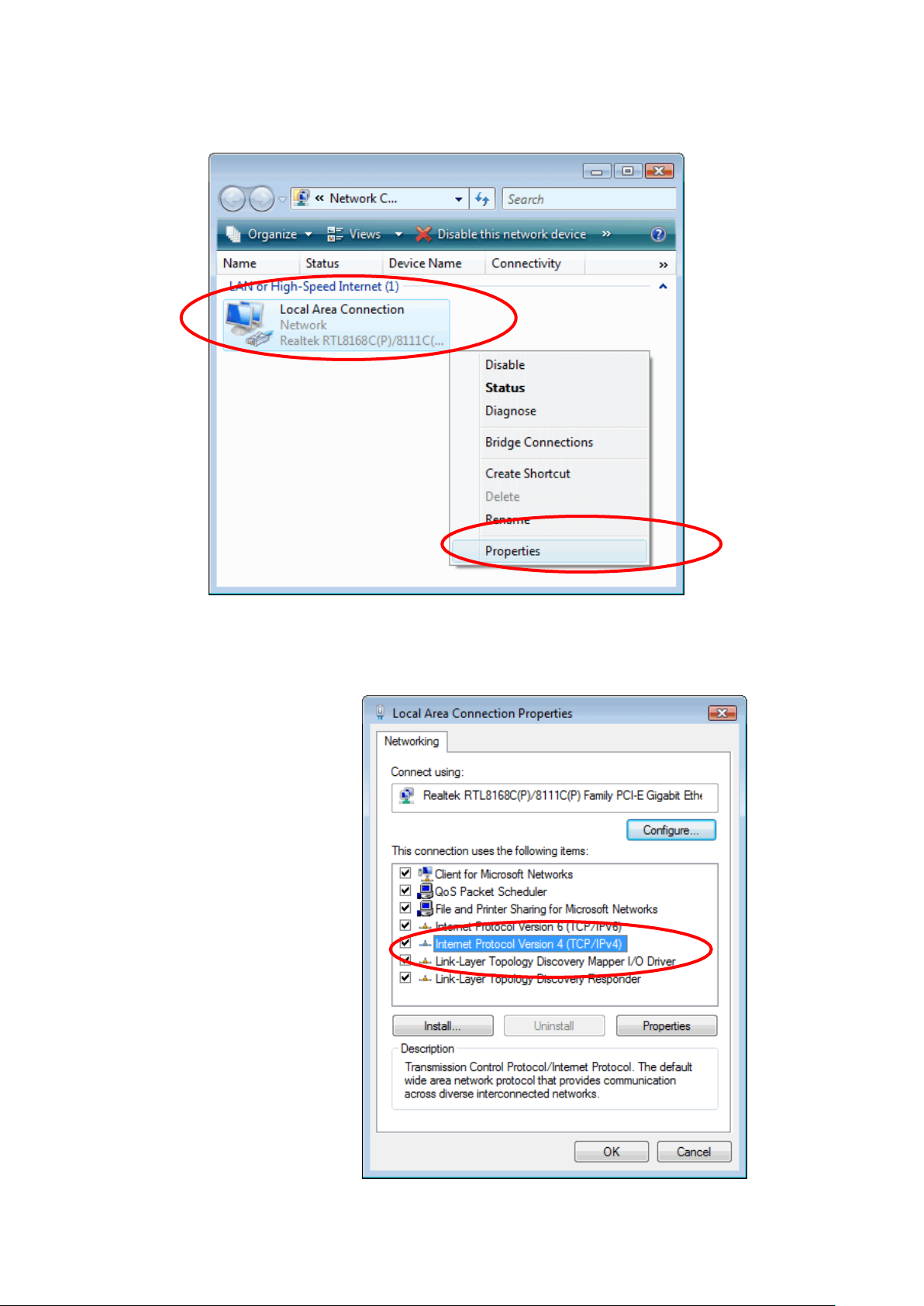
3. Single RIGHT click on "Local Area connection", then click
"Properties".
4. The screen will display the information "User Account
Control" and click "Continue" to continue.
5. Double click on "Internet Protocol Version 4 (TCP/IPv4)".
Page 14
14
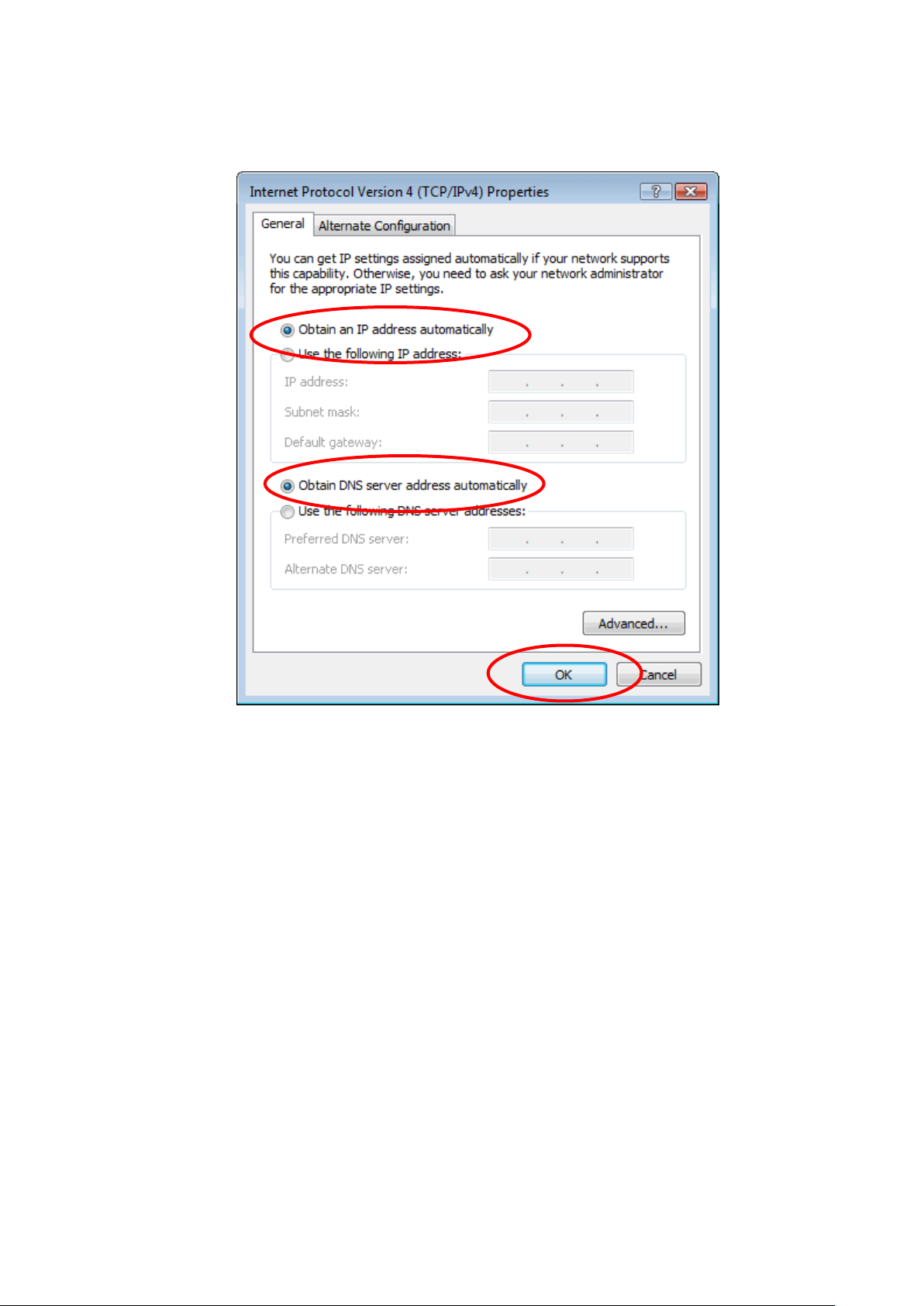
6. Check "Obtain an IP address automatically" and "Obtain
DNS server address automatically" then click on "OK" to
continue.
Page 15

15
For Windows 7-32/64
7. Click on “Start” -> “Control Panel” (in Category View) ->
“View network status and tasks”.
8. In the Control Panel Home, click on “Change adapter
settings” to continue.
Page 16
16
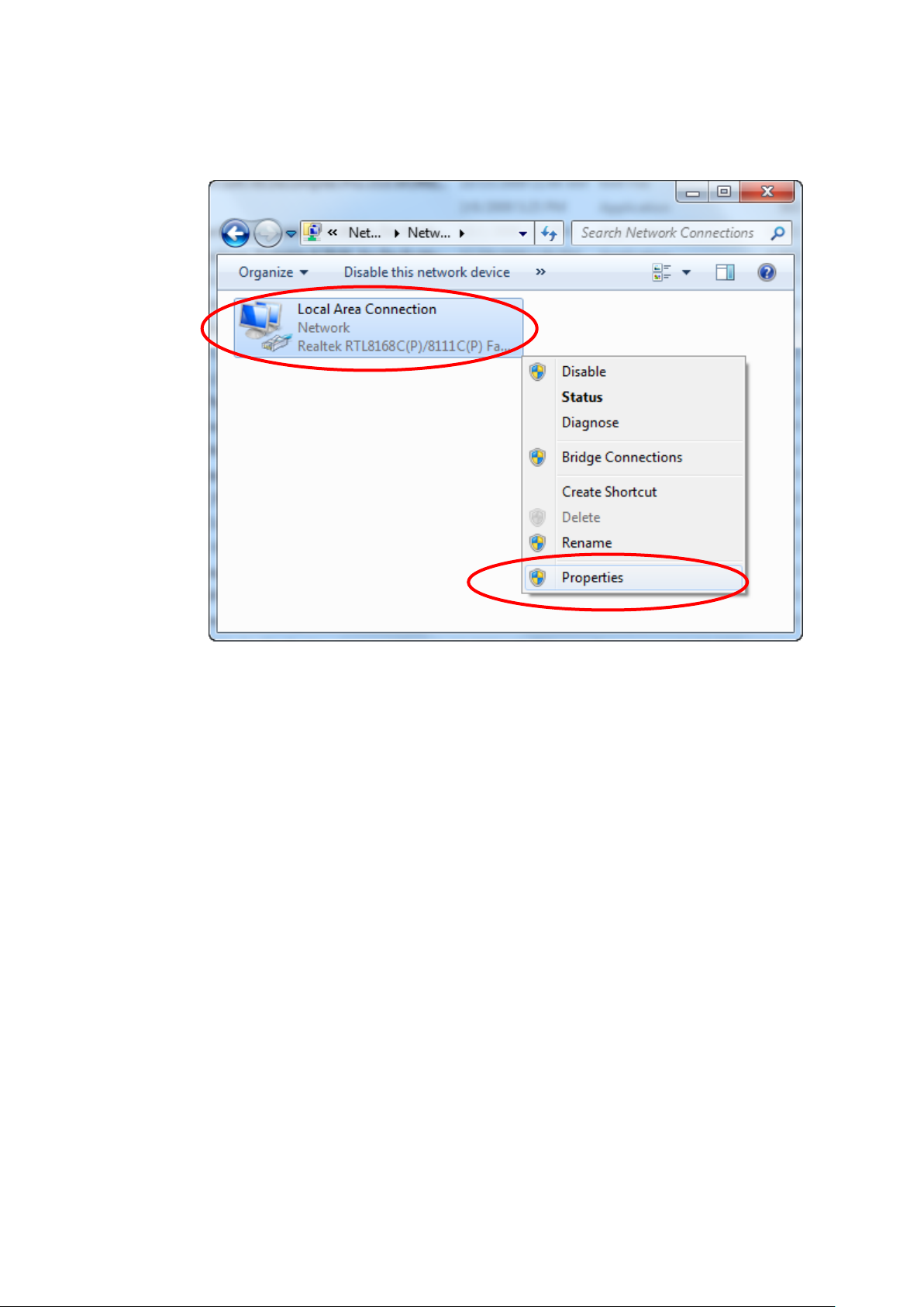
9. Single RIGHT click on “Local Area Connection”, then click
“Properties”.
10. Double click on "Internet Protocol Version 4 (TCP/IPv4)".
Page 17
17
11. Check "Obtain an IP address automatically" and "Obtain
DNS server address automatically" then click on "OK" to
continue.
Page 18
18
Page 19
19
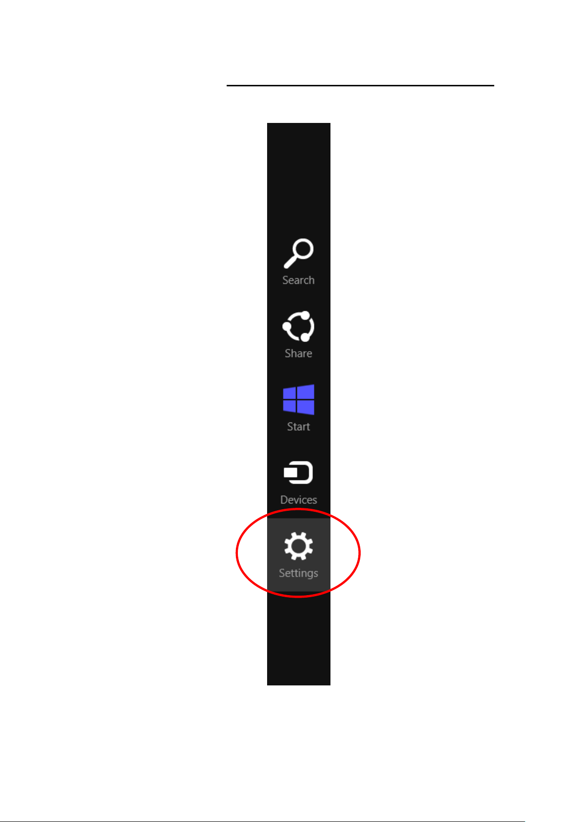
For Windows 8/8.1-32/64
1. Move the mouse or tap to the upper right corner and click
on “Settings”.
Page 20
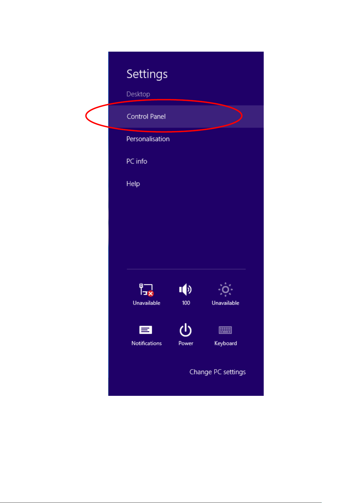
20
2. Click on “Control Panel”.
Page 21
21
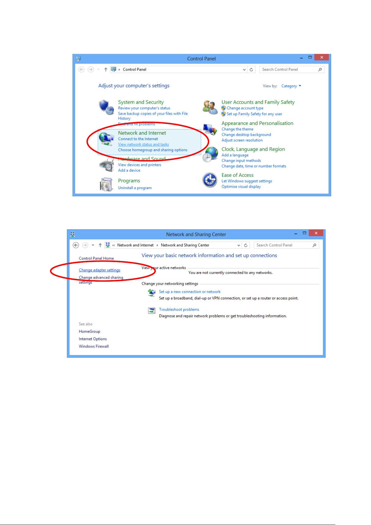
3. Click on “View network status and tasks”.
4. In the Control Panel Home, click on “Change adapter
settings” to continue.
Page 22

22
5. Single RIGHT click on “Ethernet", then click "Properties".
6. Double click on "Internet Protocol Version 4 (TCP/IPv4)".
Page 23
23
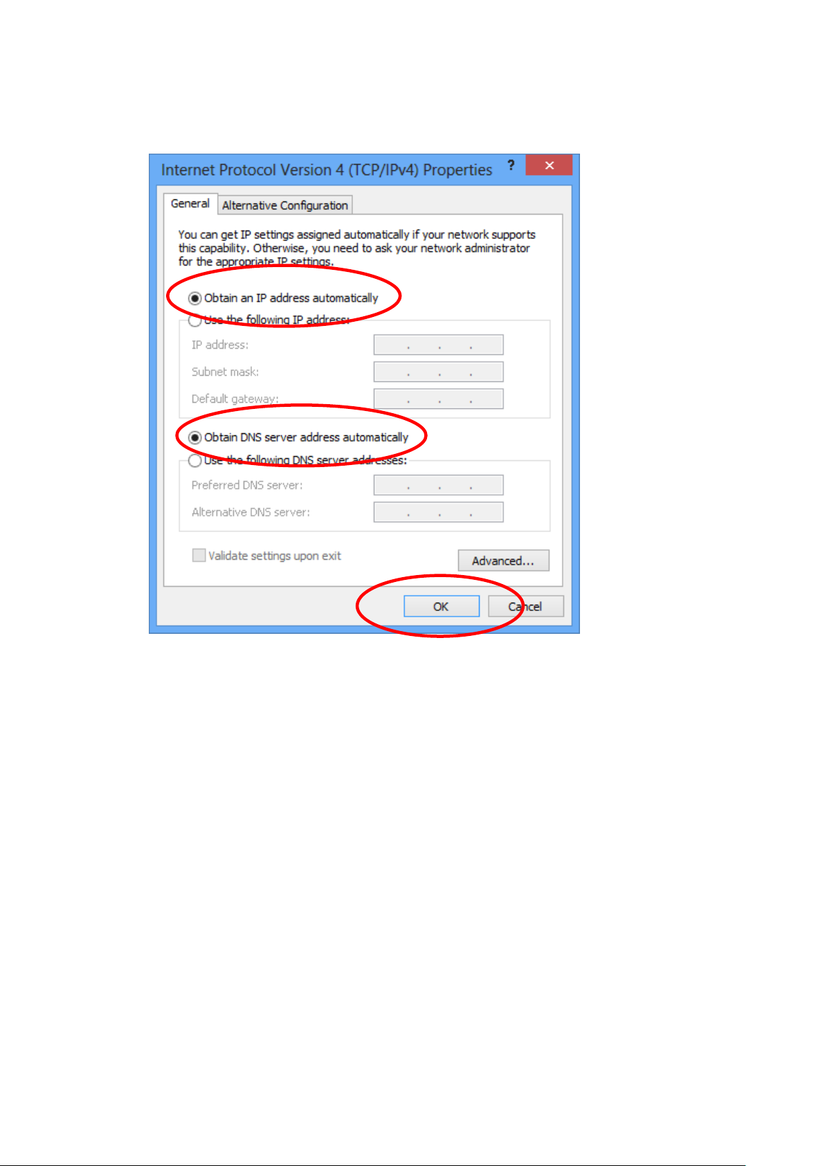
7. Check "Obtain an IP address automatically" and “Obtain
DNS server address automatically” then click on "OK" to
continue.
Page 24
24
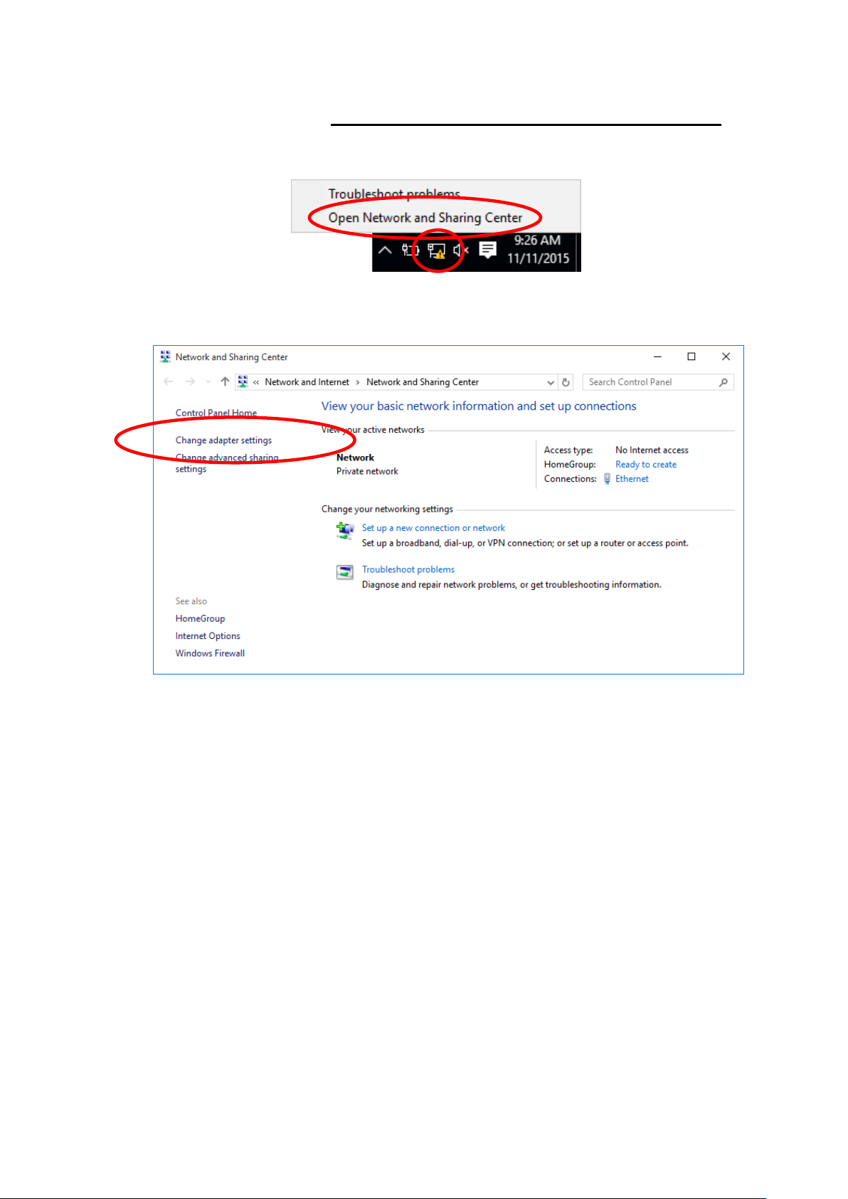
For Windows 10-32/64
1. Right click on Network icon , then click "Open Network
and Sharing Center".
2. In the Control Panel Home, click on “Change adapter
settings” to continue.
Page 25
25
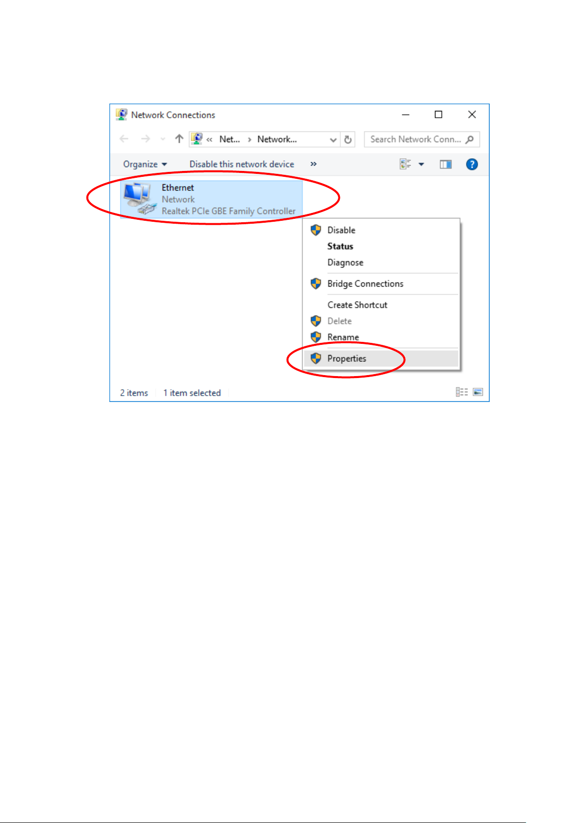
3. Single RIGHT click on “Ethernet", then click "Properties".
Page 26
26
4. Double click on "Internet Protocol Version 4 (TCP/IPv4)".
Page 27
27
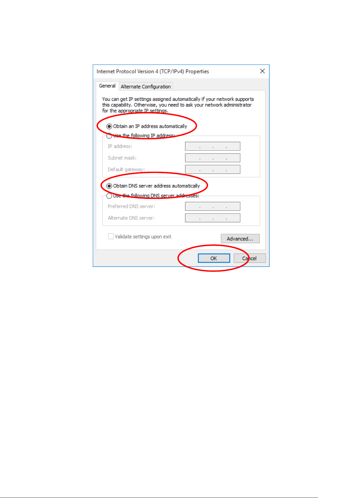
5. Check "Obtain an IP address automatically" and “Obtain
DNS server address automatically” then click on "OK" to
continue.
Page 28
28
WARNING
Before you begin, turn the power off for all devices. These
include your computer(s), your LAN hub/switch (if applicable),
and the Portable Repeater.
4 Connecting your device
This chapter provides basic instructions for connecting the
Portable Repeater to a computer or LAN and to the Internet.
In addition to configuring the device, you need to configure the
Internet properties of your computer(s). For more details, see
the following sections:
Configuring Ethernet PCs
This chapter assumes that you have already established a
DSL/Cable service with your Internet service provider (ISP).
These instructions provide a basic configuration that should be
compatible with your home or small office network setup. Refer
to the subsequent chapters for additional configuration
instructions.
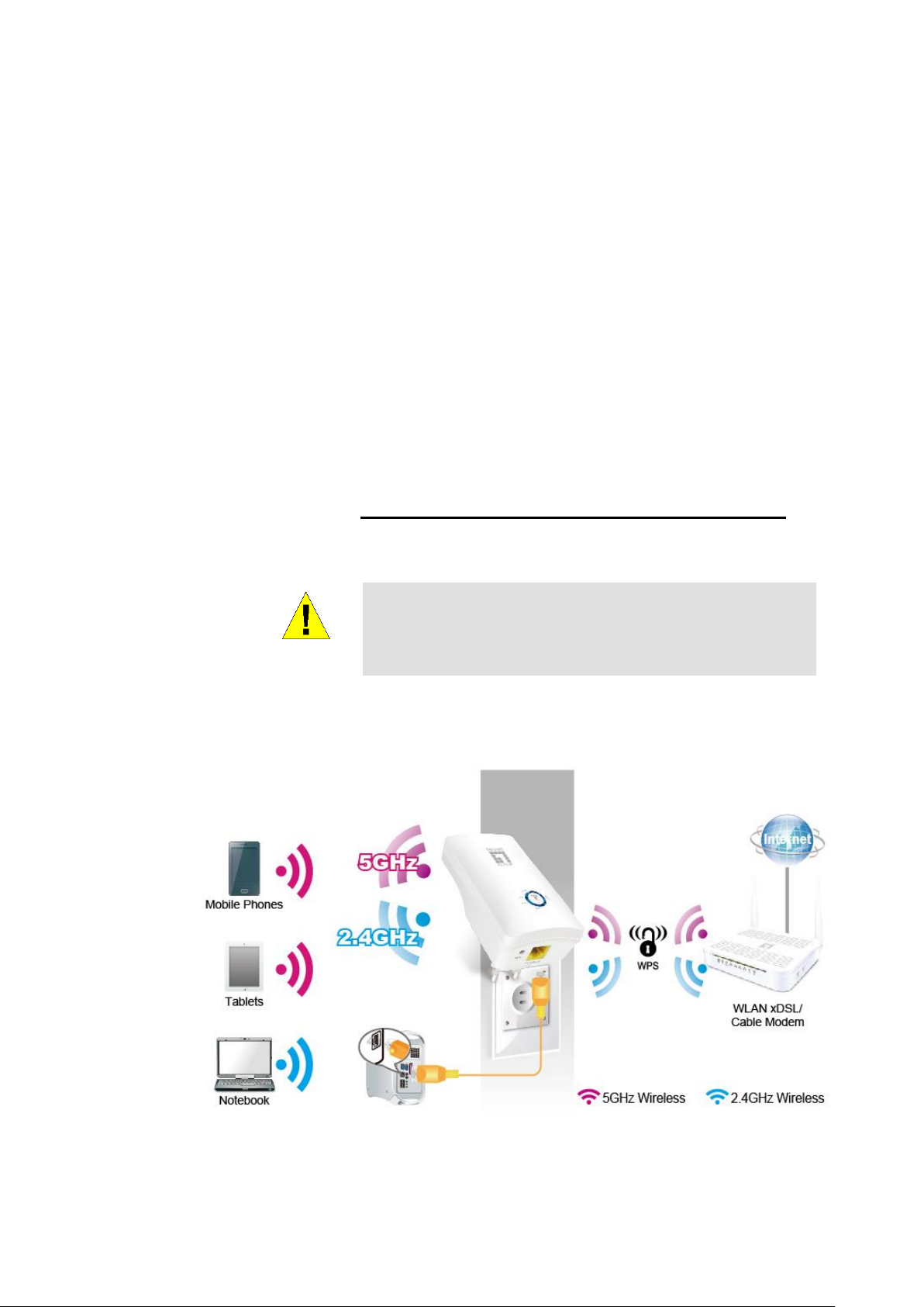
Connecting the Hardware
This section describes how to connect the device to the wall
phone port, the power outlet and your computer(s) or network.
The diagram below illustrates the hardware connections. The
layout of the ports on your device may vary from the layout
shown. Refer to the steps that follow for specific instructions.
Step 1. Connect the Ethernet cable to LAN Port
Connect the supplied RJ45 Ethernet cable from your PC's
Ethernet port to any of the WRE-8011E LAN Port.
Page 29
29
Step 2. Connect the WRE-8011E to your wall-mounted
power outlet
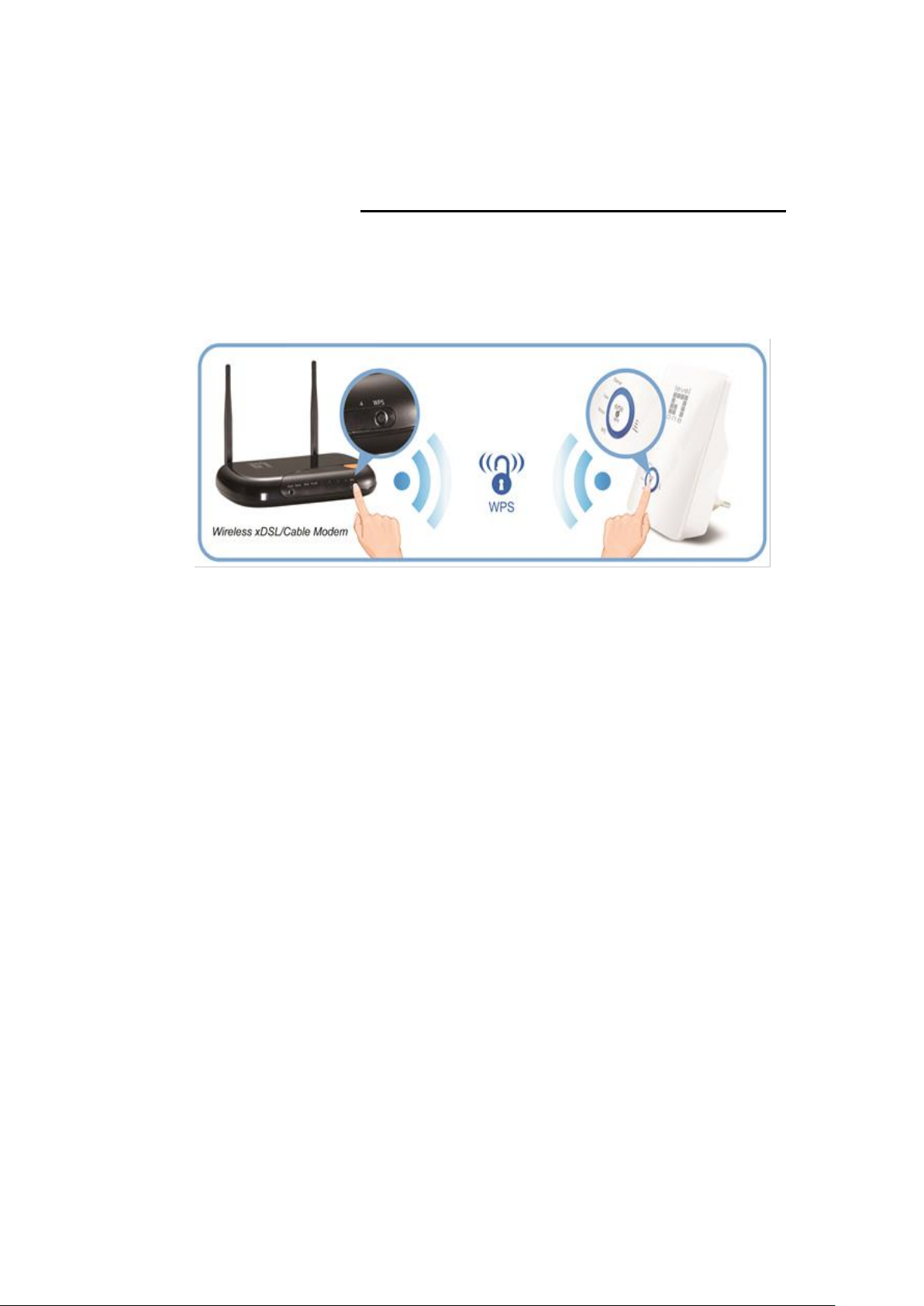
WPS Pairing between WRE-8011E and Wireless
xDSL/Cable Modem
This section describes how to do WPS Pairing between WRE8011E and Wireless xDSL/Cable.
The diagram below illustrates the hardware connections. The
layout of the ports on your device may vary from the layout
shown. Refer to the steps that follow for specific instructions.
Step 1. Press WPS button on Wireless xDSL/Cable Modem.
Step 2. Press WPS button on WRE-8011E for 3 seconds
and release WPS button. Now the WPS LED is blinking and
the WRE-8011E is donig WPS Pairing with Wireless
xDSL/Cable Modem.
Make sure to press the button within 120 seconds (2
minutes) after pressing the Wireless xDSL/Cable Modem's
WPS button.
Step 3. Once the WRE-8011E finished doing WPS Pairing
with Wireless xDSL/Cable Modem, the Wifi Signal Strength
LED is ON. The status of Wifi signal strength LED varies
depending on the Wifi signal strength between WRE-8011E
and Wireless xDSL/Cable Modem.
Step 4. Check if the Wifi Signal Strength LED of WRE8011E is ON, the WRE-8011E is connected and suitable for
Internet Connections.
Step 5. Check if the Wifi Signal Strength is OFF, the WRE8011E isn’t connected and suitable for Internet
Connections. Please repeat steps of WPS Pairing or follow
next step to have it connected and suitable for Internet
Connections.
Page 30
30
5 Advanced Configuration
Advanced Configuration
1. From any of the LAN computers connected to , launch your
web browser, type the following URL in the web address (or
location) box, and press [Enter] on your keyboard:
http://repeater.nw
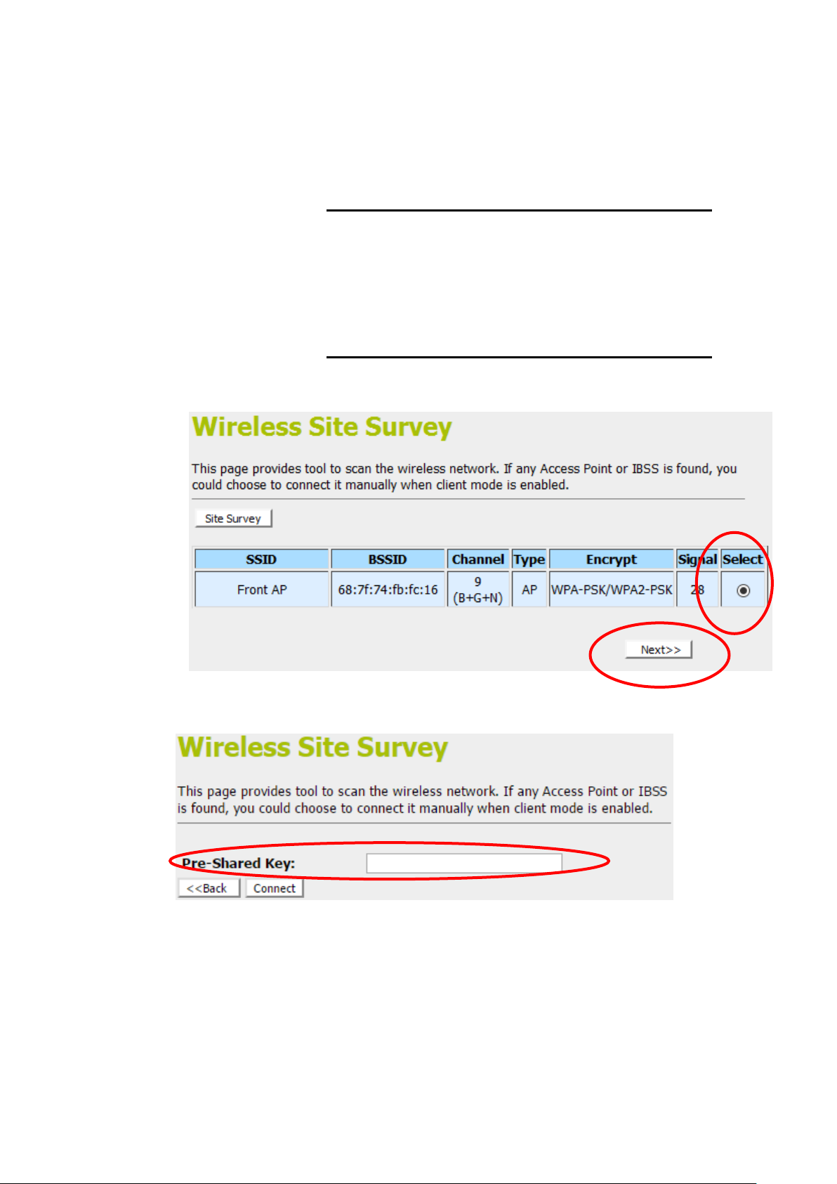
Repeater Mode (Extend your Wireless Network)
2. Check on “Select” ratio of SSID of the front AP and click on
“Next>>” button.
3. Enter Wifi password of the front AP and then click on
“Connect” button.
Page 31

31
4. Please wait... 140 s
AP Mode (Extend your Wired Network to allow
wireless devices to connect your wired network
using Wi-Fi)
5. Click on “TCP/IP Settings -> LAN SETTING” from left
menu.
6. Select on “Client” from DHCP drop-down list.
7. Click on “Save & Apply” button.
Page 32

32
8. Change setting successfully! Do not turn off or reboot the
Device during this time. Please wait 20 seconds ...
9. Please disconnect the Ethernet Cable from PC and connect
it to the LAN port of xDSL/Cable Modem.
10. Please wait for 2 minutes.
11. Now, the WRE-8011E has been configured completed, and
suitable for Wireless and Internet Connections.
Wireless Connection
For easy installation it is saved to keep the settings. You can
later change the wireless settings via the wireless configuration
menu.
1. Double click on the network icon on your computer and
search for the wireless network that you enter SSID name.
2. Click on the wireless network that you enter SSID name
(the default settings, Wireless Network = Enable, Default
Channel = Auto, SSID = LevelOne 5G for 5GHz and
LevelOne 2.4G for 2.4GHz) to connect.
3. If the wireless network isn’t encrypted, click on "Connect "
to connect.
Page 33

33
4. If the wireless network is encrypted, enter your own
wireless password at least 8 characters for example
12345678 in the key field / Network key field / Confirm
Network key field (the default settings Security Mode =
None). You can later change this network key via the
wireless configuration menu.
5. Click on "Next".
6. Now you are ready to use the Wireless Network to Internet
or intranet.
Page 34

34
6 What the Internet/WAN access of your own
Network now is
Now you could check what the Internet/WAN access of your
network is to know how to configure the WAN port of Portable
Repeater.
Please follow steps below to check what the Internet/WAN
access if your own Network is DHCP Client, Static IP or PPPoE
Client.
1. Click Start -> Control Panel
Page 35

35
2. Double click Network Connections
Page 36

36
Internet/WAN access is the DHCP client
If you cannot see any Broadband Adapter in the Network
Connections, your Internet/WAN access is DHCP Client or
Static IP.
3. Click Local Area Connection in LAN or High-Speed
Internet and you could see string Assigned by DHCP in
Details.
Page 37

37
Internet/WAN access is the Static IP
If you cannot see any Broadband Adapter in the Network
Connections, your Internet/WAN access is DHCP Client or
Static IP.
4. Click Local Area Connection in LAN or High-Speed
Internet and you could see string Manually Configured in
Details.
Page 38

38
5. Right click Local Area Connection and click Properties
and then you could get the IP settings in detail and write
down the IP settings as follow:
IP Address: 192.168.10.110
Subnet mask: 255.255.255.0
Default gateway: 192.168.10.100
Preferred DNS server: 192.168.10.100
Alternate DNS Server: If you have it, please also write it
down.
Page 39

39
Internet/WAN access is the PPPoE client
If you can see any Broadband Adapter in the Network
Connections, your Internet/WAN access is PPPoE Client.
6. Click Broadband Adapter in Broadband and you could
see string Assigned by Service Provider in Details.
For PPPoE configuration on Portable Repeater, you’ll need
following information that you could get from your Telecom, or
by your Internet Service Provider.
Username of PPPoE: 1234 for example
Password of PPPoE: 1234 for example
Page 40

40
Note
If you receive an error message or the Welcome page is not
displayed, see Troubleshooting Suggestions.
7 Getting Started with the Web pages
The Portable Repeater includes a series of Web pages that
provide an interface to the software installed on the device. It
enables you to configure the device settings to meet the needs
of your network. You can access it through your web browser
from any PC connected to the device via the LAN ports.
Accessing the Web pages
To access the Web pages, you need the following:
A PC or laptop connected to the LAN port on the device.
A web browser installed on the PC. The minimum browser
version requirement is Internet Explorer v4 or Netscape v4.
For the best display quality, use latest version of Internet
Explorer, Netscape or Mozilla Fire fox. From any of the LAN
computers, launch your web browser, type the following
URL in the web address (or location) box, and press [Enter]
on your keyboard:
http://repeater.nw
The Quick Setup homepage for the web pages is displayed:
Figure 2: Homepage
1. You are now ready to configure your device.
This is the first page displayed each time you log in to the Web
pages.
Page 41

41
Label
Color
Function
POWER
green
On: device is powered on
Off: device is powered off
WLAN
green
On: WLAN link established and active
Blink: Valid Wireless packet being transferred
LAN
green
On: LAN link established and active
Off: No LAN link
Blink: Valid Ethernet packet being transferred
WARNING
We strongly recommend that you contact your ISP prior to
changing the default configuration.
Testing your Setup
Once you have connected your hardware and configured your
PCs, any computer on your LAN should be able to use the DSL
/Cable connection to access the Internet.
To test the connection, turn on the device, wait for 30 seconds
and then verify that the LEDs are illuminated as follows:
Table 1. LED Indicators
If the LEDs illuminate as expected, test your Internet connection
from a LAN computer. To do this, open your web browser, and
type the URL of any external website (such as
http://www.yahoo.com). The LED labeled WAN should blink
rapidly and then appear solid as the device connects to the site.
If the LEDs do not illuminate as expected, you may need to
configure your Internet access settings using the information
provided by your ISP. For details, see Internet Access. If the
LEDs still do not illuminate as expected or the web page is not
displayed, see Troubleshooting Suggestions or contact your
ISP for assistance.
Default device settings
In addition to handling the xDSL / Cable modem connection to
your ISP, the Portable Repeater can provide a variety of
services to your network. The device is preconfigured with
default settings for use with a typical home or small office
network.
The table below lists some of the most important default settings;
these and other features are described fully in the subsequent
chapters. If you are familiar with network configuration, review
these settings to verify that they meet the needs of your network.
Follow the instructions to change them if necessary. If you are
unfamiliar with these settings, try using the device without
modification, or contact your ISP for assistance.
Page 42

42
Option
Default Setting
Explanation/Instructions
WAN Port IP
Address
DHCP Client
This is the temporary public IP address of the WAN
port on the device. It is an unnumbered interface that
is replaced as soon as your ISP assigns a ‘real’ IP
address. See Network Settings -> WAN Interface.
LAN Port
IP Address
Assigned static IP address:
192.168.1.1
Subnet mask:
255.255.255.0
This is the IP address of the LAN port on the device.
The LAN port connects the device to your Ethernet
network. Typically, you will not need to change this
address. See Network Settings -> LAN Interface.
DHCP (Dynamic
Host Configuration
Protocol)
DHCP server enabled with the
following pool of addresses:
192.168.1.100
through
192.168.1.200
The Portable Repeater maintains a pool of private IP
addresses for dynamic assignment to your LAN
computers. To use this service, you must have set up
your computers to accept IP information dynamically,
as described in Configuring Ethernet PCs.
Page 43

43
8 Quick Setup
The Quick Setup page displays useful information about the
setup of your device, including:
details of the device’s Internet access settings
details of the device’s VoIP settings
details of the device’s Wireless settings
To display this page:
From the head menu, click on Setup. The following page is
displayed:
Figure 3: Quick Setup page
Page 44

44
Repeater Mode (Extend your Wireless Network)
1. Check on “Select” ratio of SSID of the front AP and click on
“Next>>” button.
2. Configure related parameters and then click on “Connect”
button.
3. Please wait....
Page 45

45
4. Click on “Reboot Now” button.
5. Change setting successfully! Do not turn off or reboot the
Device during this time. Please wait 20 seconds ...
AP Mode (Extend your Wired Network to allow
wireless devices to connect your wired network
using Wi-Fi)
6. Click on “TCP/IP Settings -> LAN SETTING” from left
menu.
7. Select on “Client” from DHCP drop-down list.
8. Click on “Save & Apply” button.
Page 46

46
9. Change setting successfully! Do not turn off or reboot the
Device during this time. Please wait 20 seconds ...
10. Please disconnect the Ethernet Cable from PC and connect
it to the LAN port of xDSL/Cable Modem.
11. Now, the WRE-8011E has been configured completed, and
suitable for Wireless and Internet Connections.
Page 47

47
Note
You should only change the addressing details if your ISP asks
you to, or if you are familiar with network configuration. In most
cases, you will not need to make any changes to this
configuration.
9 LAN Interface
This chapter is to configure the parameters for local area
network which connects to the LAN port of your Access Point.
Here you may change the setting for IP address, subnet mask,
DHCP, etc...
LAN Interface Setup
To check the configuration of LAN Interface:
1. From the left-hand menu, click on TCP/IP Settings -> LAN
SETTING. The following page is displayed:
Page 48

48
Field
Description
IP Address
The IP address of your router on the local area network. Your local
area network settings are based on the address assigned here.
Subnet Mask
The subnet mask of your router on the local area network.
DHCP Mode
Once your router is properly configured and DHCP Server is
enabled, the DHCP Server will manage the IP addresses and other
network configuration information for computers and other devices
connected to your Local Area Network. There is no need for you to
do this yourself.
The computers (and other devices) connected to your LAN also
need to have their TCP/IP configuration set to "DHCP" or "Obtain an
IP address automatically".
IP Pool Range
These two IP values (from and to) define a range of IP addresses
that the DHCP Server uses when assigning addresses to computers
and devices on your Local Area Network. Any addresses that are
outside of this range are not managed by the DHCP Server; these
could, therefore, be used for manually configured devices or
devices that cannot use DHCP to obtain network address details
automatically.
Your router, by default, has a static IP address of 192.168.0.1. This
means that addresses 192.168.0.2 to 192.168.0.254 can be made
available for allocation by the DHCP Server.
Max Lease Time
The amount of time that a computer may have an IP address before
it is required to renew the lease. The lease functions just as a lease
on an apartment would. The initial lease designates the amount of
time before the lease expires. If the tenant wishes to retain the
address when the lease is expired then a new lease is established. If
the lease expires and the address is no longer needed then another
tenant may use the address.
Domain Name
Domain name for the dhcp server scope.
IP Address
The IP address to be configured for your computer or device on the
local area network.For example, 192.168.0.2.
Mac Address
The mac address of your computer or device on the local area
network.
Page 49

49
Changing the LAN IP address and subnet mask
To Change the configuration of LAN Interface:
1. From the left-hand menu, click on TCP/IP Settings -> LAN
Interface. The following page is displayed:
Page 50

50
2. Change the IP Address and Subnet Mask and DHCP Client
Range.
3. Click Save & Apply.
4. Change setting successfully! Do not turn off or reboot the
Device during this time. Please wait 15 seconds ....
Page 51

51
Note
If you change the LAN IP address of the device while connected
through your Web browser, you will be disconnected. You must
open a new connection by entering your new LAN IP address as
the URL.
You may also need to renew your DHCP lease:
Windows 95/98
a. Select Run... from the Start menu.
b. Enter winipcfg and click OK.
c. Select your ethernet adaptor from the pull-down menu
d. Click Release All and then Renew All.
e. Exit the winipcfg dialog.
Windows NT/Windows 2000/Windows XP
a. Bring up a command window.
b. Type ipconfig /release in the command window.
c. Type ipconfig /renew.
d. Type exit to close the command window.
Linux
a. Bring up a shell.
b. Type pump -r to release the lease.
c. Type pump to renew the lease.
Page 52

52
DHCP Static IP Configuration
If you need to assign static ip for your computer or device on the
local area network, configure static ip with the mac address.:
1. From the left-hand menu, click on TCP/IP Settings -> LAN
Interface. The following page is displayed:
2. Click Set Static DHCP
3. Enable Static DHCP.
4. Enter the IP Address.
5. Enter the Mac Address.
6. Click Add.
Page 53

53
7. Click Reboot Now.
8. The DHCP Static IP Configuration that you created has
been added in the DHCP Static IP Table.
Page 54

54
10 Wireless Network - 5GHz
This chapter assumes that you have already set up your
Wireless PCs and installed a compatible Wireless card on your
device. See Configuring Wireless PCs.
Wireless Basics
The Wireless Network page allows you to configure the
Wireless features of your device. To access the Wireless Basics
page:
From the Wireless menu, click on WLAN1 -> BASIC SETTING.
The following page is displayed:
Page 55

55
Page 56

56
Field
Description
Disable
Wireless LAN
Interface
Enable/Disable the Wireless LAN Interface.
Default: Disable
Band
Specify the WLAN Mode to 802.11b/g Mixed mode, 802.11b mode or
802.11g mode
Mode
Configure the Wireless LAN Interface to AP, Client, WDS, AP + WDS,
MESH or AP + MESH mode
Network Type
Configure the Network Type to Infrastructure or Ad hoc.
SSID
Specify the network name.
Each Wireless LAN network uses a unique Network Name to identify the
network. This name is called the Service Set Identifier (SSID). When you
set up your wireless adapter, you specify the SSID. If you want to
connect to an existing network, you must use the name for that
network. If you are setting up your own network you can make up your
own name and use it on each computer. The name can be up to 20
characters long and contain letters and numbers.
Channel Width
Choose a Channel Width from the pull-down menu.
Control
Sideband
Choose a Control Sideband from the pull-down menu.
Channel
Number
Choose a Channel Number from the pull-down menu.
Broadcast SSID
Broadcast or Hide SSID to your Network.
Default: Enabled
WMM
Enable/disable the Wi-Fi Multimedia (WMM) support.
Data Rate
Select the Data Rate from the drop-down list
Associated
Clients
Show Active Wireless Client Table
This table shows the MAC address, transmission, receiption packet
counters and encrypted status for each associated wireless client.
Enable Mac
Clone (Single
Ethernet Client)
Enable Mac Clone (Single Ethernet Client)
Enable
Universal
Repeater Mode
Acting as AP and client simultaneously
SSID of
Extended
Interface
When mode is set to “AP” and URM (Universal Repeater Mode ) is
enabled, user should input SSID of another AP in the field of “SSID of
Extended Interface”. Please note, the channel number should be set to
the one, used by another AP because 8186 will share the same channel
between AP and URM interface (called as extended interface hereafter).
Figure 4: Wireless Network page
Page 57

57
Field
Description
Fragment
Threshold
When transmitting a packet over a network medium, sometimes the
packet is broken into several segments, if the size of packet exceeds
that allowed by the network medium.
The Fragmentation Threshold defines the number of bytes used for the
fragmentation boundary for directed messages.
RTS Threshold
RTS stands for “Request to Send”. This parameter controls what size
data packet the low level RF protocol issues to an RTS packet. The
default is 2347.
Advanced Settings
These settings are only for more technically advanced users
who have a sufficient knowledge about wireless LAN. These
settings should not be changed unless you know what effect the
changes will have on your Access Point. To access the
Wireless Network Advanced Settings page:
From the left-hand Wireless menu, click on WLAN1 ->
Advanced Settings. The following page is displayed:
Page 58

58
Beacon Interval
Choosing beacon period for improved response time for wireless http
clients.
Preamble Type
Specify the Preamble type is short preamble or long preamble
IAPP
Disable or Enable IAPP
Protection
A protection mechanism prevents collisions among 802.11g nodes.
Aggregation
Disable or Enable Aggregation
Short GI
Disable or Enable Short GI
WLAN Partition
Disable or Enable WLAN Partition
STBC
Disable or Enable STBC
20/40MHz
Coexist
Disable or Enable 20/40MHz Coexist
RF Output
Power
TX Power measurement.
Page 59

59
Field
Description
Select SSID
Select the SSID
Encryption
Configure the Encryption to Disable, WEP, WPA , WPA2 or WPA-Mixed
Use 802.1x
Authentication
Use 802.1x Authentication by WEP 64bits or WEP 128bits
Authentication
Configure the Authentication Mode to Open System, Shared Key or
Auto
Key Length
Select the Key Length 64-bit or 128-bit
Key Format
Select the Key Format ASCII (5 characters), Hex (10 characters), ASCII
(13 characters) or Hex (26 characters)
Encryption Key
Enter the Encryption Key
WPA
Authentication
Mode
Configure the WPA Authentication Mode to Enterprise (RADIUS) or
Personal (Pre-Shared Key)
WPA Cipher
Suite
Configure the WPA Cipher Suite to AES
Field
Description
WPA2 Cipher
Suite
Configure the WPA2 Cipher Suite to AES
Pre-Shared Key
Configure the Pre-Shared Key Format to Passphrase or HEX (64
Security
This page allows you setup the wireless security. Turn on WEP
or WPA by using Encryption Keys could prevent any
unauthorized access to your wireless network. To access the
Wireless Network Security page:
From the left-hand Wireless menu, click on WLAN1 -> Security.
The following page is displayed:
Page 60

60
Format
characters)
Pre-Shared Key
Type the Pre-Shared Key
Enable PreAuthentication
According to some of the preferred embodiments, a method for
proactively establishing a security association between a mobile node
in a visiting network and an authentication agent in another network to
which the mobile node can move includes: negotiating preauthentication using a flag in a message header that indicates whether
the communication is for establishing a pre-authentication security
association; and one of the mobile node and the authentication agent
initiating pre-authentication by transmitting a message with the flag set
in its message header, and the other of the mobile node and the
authentication agent responding with the flag set in its message header
only if it supports the pre-authentication. Enable/disable preauthentication support. Default: disable.
Authentication
RADIUS Server
Port: Type the port number of RADIUS Server
IP address: Type the IP address of RADIUS Server
Password: Type the Password of RADIUS Server
Page 61

61
WEP + Encryption Key
WEP aims to provide security by encrypting data over radio
waves so that it is protected as it is transmitted from one end
point to another. However, it has been found that WEP is not as
secure as once believed.
1. From the Encryption drop-down list, select WEP setting.
2. From the Key Length drop-down list, select 64 -bit or 128-bit
setting.
3. From the Key Format drop-down list, select ASCII (5
characters), Hex (10 characters), ASCII (13 characters) or
Hex (26 characters) setting.
4. Enter the Encryption Key value depending on selected
ASCII or Hexadecimal.
5. Click Save & Apply button.
6. Click OK button.
Page 62

62
7. Change setting successfully! Do not turn off or reboot the
Device during this time. Please wait 20 seconds ...
WEP + Use 802.1x Authentication
WEP aims to provide security by encrypting data over radio
waves so that it is protected as it is transmitted from one end
point to another. However, it has been found that WEP is not as
secure as once believed.
1. From the Encryption drop-down list, select WEP setting.
2. Check the option of Use 802.1x Authentication.
3. Click on the ratio of WEP 64bits or WEP 128bits.
4. Enter the Port, IP Address and Password of RADIUS
Server:
5. Click Save & Apply button.
Page 63

63
6. Click OK button.
7. Change setting successfully! Do not turn off or reboot the
Device during this time. Please wait 20 seconds ...
WPA2/WPA Mixed + Personal (Pre-Shared Key)
Wi-Fi Protected Access (WPA and WPA2) is a class of systems
to secure wireless (Wi-Fi)
computer networks. WPA is designed to work with all wireless
network interface cards, but not necessarily with first generation
wireless access points. WPA2 implements the full standard, but
will not work with some older network cards. Both provide good
security, with two significant issues:
Either WPA or WPA2 must be enabled and chosen in
preference to WEP. WEP is usually presented as the first
security choice in most installation instructions.
In the "Personal" mode, the most likely choice for homes
and small offices, a pass phrase is required that, for full
security, must be longer than the typical 6 to 8 character
passwords users are taught to employ.
1. From the Encryption drop-down list, select WPA2 or WPA
Mixed setting.
2. Click on the ratio of Personal (Pre-Shared Key).
3. Check the option of AES in WPA2 Cipher Suite if your
Encryption is WPA2:
Page 64

64
4. Check the option of TKIP and/or AES in WPA/WPA2
Cipher Suite if your Encryption is WPA Mixed:
5. From the Pre-Shared Key Format drop-down list, select
Passphrase or Hex (64 characters) setting.
6. Enter the Pre-Shared Key depending on selected
Passphrase or Hex (64 characters).
7. Click on Save & Apply button to confirm and return.
8. Change setting successfully! Do not turn off or reboot the
Device during this time. Please wait 20 seconds ...
WPA2/WPA Mixed + Enterprise (RADIUS)
Wi-Fi Protected Access (WPA and WPA2) is a class of systems
to secure wireless (Wi-Fi) computer networks. WPA is designed
to work with all wireless network interface cards, but not
necessarily with first generation wireless access points. WPA2
implements the full standard, but will not work with some older
network cards. Both provide good security, with two significant
issues:
Either WPA or WPA2 must be enabled and chosen in
preference to WEP. WEP is usually presented as the first
security choice in most installation instructions.
In the "Personal" mode, the most likely choice for homes
and small offices, a pass phrase is required that, for full
security, must be longer than the typical 6 to 8 character
passwords users are taught to employ.
1. From the Encryption drop-down list, select WPA2 or WPA
Mixed setting.
Page 65

65
2. Click on the ratio of Enterprise (RADIUS).
3. Check the option of AES in WPA2 Cipher Suite if your
Encryption is WPA2:
4. Check the option of TKIP and/or AES in WPA/WPA2
Cipher Suite if your Encryption is WPA Mixed:
5. Enter the Port, IP Address and Password of RADIUS
Server:
6. Click on Save & Apply button to confirm and return.
7. Change setting successfully! Do not turn off or reboot the
Device during this time. Please wait 20 seconds ...
Page 66

66
Wireless Access Control Mode
For security reason, using MAC ACL's (MAC Address Access
List) creates another level of difficulty to hacking a network. A
MAC ACL is created and distributed to AP so that only
authorized NIC's can connect to the network. While MAC
address spoofing is a proven means to hacking a network this
can be used in conjunction with additional security measures to
increase the level of complexity of the network security
decreasing the chance of a breach.
MAC addresses can be add/delete/edit from the ACL list
depending on the MAC Access Policy.
If you choose 'Allowed Listed', only those clients whose wireless
MAC addresses are in the access control list will be able to
connect to your Access Point. When 'Deny Listed' is selected,
these wireless clients on the list will not be able to connect the
Access Point. To access the Wireless Network Access Control
page:
From the left-hand Wireless menu, click on WLAN1 -> Access
Control. The following page is displayed:
Page 67

67
Allow Listed
If you choose 'Allowed Listed', only those clients whose wireless
MAC addresses are in the access control list will be able to
connect to your Access Point.
1. From the Wireless Access Control Mode drop-down list,
select Allowed Listed setting.
2. Enter the MAC Address.
3. Enter the Comment.
4. Click Save & Apply button.
5. Click OK button.
6. Change setting successfully! Do not turn off or reboot the
Device during this time. Please wait 20 seconds ...
7. The MAC Address that you created has been added in the
Current Access Control List.
Page 68

68
Deny Listed
When 'Deny Listed' is selected, these wireless clients on the list
will not be able to connect the Access Point.
1. From the Wireless Access Control Mode drop-down list,
select Deny Listed setting.
2. Enter the MAC Address.
3. Enter the Comment.
4. Click Save & Apply button.
5. Change setting successfully! Do not turn off or reboot the
Device during this time. Please wait 20 seconds ...
Page 69

69
Field
Description
Disable WPS
Checking this box and clicking “Save & Apply” will disable Wi-Fi
Protected Setup. WPS is turned on by default.
Self-PIN Number
“Self-PIN Number” is AP’s PIN. Whenever users want to change
AP’s PIN, they could click “Regenerate PIN” and then click “ Save &
Apply”. Moreover, if users want to make their own PIN, they could
enter four digit PIN without checksum and then click “ Save &
Apply”. However, this would not be recommended since the
registrar side needs to be supported with four digit PIN.
WPS
This page allows you to change the setting for WPS (Wi-Fi
Protected Setup). Using this feature could let your wireless
client automatically syncronize its setting and connect to the
Access Point in a minute without any hassle. To access the
Wireless Network WPS page:
From the left-hand Wireless menu, click on WLAN1 -> WPS.
The following page is displayed:
Page 70

70
Field
Description
Push Button
Configuration
Clicking this button will invoke the PBC method of WPS. It is only
used when AP acts as a registrar.
Save & Apply
Whenever users want to enable/disable WPS or change AP’s PIN,
they need to apply this button to commit changes.
Reset
It restores the original values of “Self-PIN Number” and “Client PIN
Number”.
Client PIN Number
It is only used when users want their station to join AP’s network.
The length of PIN is limited to four or eight numeric digits. If users
enter eight digit PIN with checksum error, there will be a warning
message popping up.
If users insist on this PIN, AP will take it.
Page 71

71
11 Wireless Network – 2.4GHz
This chapter assumes that you have already set up your
Wireless PCs and installed a compatible Wireless card on your
device. See Configuring Wireless PCs.
Wireless Basics
The Wireless Network page allows you to configure the
Wireless features of your device. To access the Wireless Basics
page:
From the Wireless menu, click on WLAN2 -> BASIC SETTING.
The following page is displayed:
Page 72

72
Figure 5: Wireless Network page
Page 73

73
Field
Description
Disable
Wireless LAN
Interface
Enable/Disable the Wireless LAN Interface.
Default: Disable
Band
Specify the WLAN Mode to 802.11b/g Mixed mode, 802.11b mode or
802.11g mode
Mode
Configure the Wireless LAN Interface to AP, Client, WDS, AP + WDS,
MESH or AP + MESH mode
Network Type
Configure the Network Type to Infrastructure or Ad hoc.
SSID
Specify the network name.
Each Wireless LAN network uses a unique Network Name to identify the
network. This name is called the Service Set Identifier (SSID). When you
set up your wireless adapter, you specify the SSID. If you want to
connect to an existing network, you must use the name for that
network. If you are setting up your own network you can make up your
own name and use it on each computer. The name can be up to 20
characters long and contain letters and numbers.
Channel Width
Choose a Channel Width from the pull-down menu.
Control
Sideband
Choose a Control Sideband from the pull-down menu.
Channel
Number
Choose a Channel Number from the pull-down menu.
Broadcast SSID
Broadcast or Hide SSID to your Network.
Default: Enabled
WMM
Enable/disable the Wi-Fi Multimedia (WMM) support.
Data Rate
Select the Data Rate from the drop-down list
Associated
Clients
Show Active Wireless Client Table
This table shows the MAC address, transmission, receiption packet
counters and encrypted status for each associated wireless client.
Enable Mac
Clone (Single
Ethernet Client)
Enable Mac Clone (Single Ethernet Client)
Enable
Universal
Repeater Mode
Acting as AP and client simultaneously
SSID of
Extended
Interface
When mode is set to “AP” and URM (Universal Repeater Mode ) is
enabled, user should input SSID of another AP in the field of “SSID of
Extended Interface”. Please note, the channel number should be set to
the one, used by another AP because 8186 will share the same channel
between AP and URM interface (called as extended interface hereafter).
Page 74

74
Field
Description
Fragment
Threshold
When transmitting a packet over a network medium, sometimes the
packet is broken into several segments, if the size of packet exceeds
that allowed by the network medium.
The Fragmentation Threshold defines the number of bytes used for the
fragmentation boundary for directed messages.
RTS Threshold
RTS stands for “Request to Send”. This parameter controls what size
data packet the low level RF protocol issues to an RTS packet. The
Advanced Settings
These settings are only for more technically advanced users
who have a sufficient knowledge about wireless LAN. These
settings should not be changed unless you know what effect the
changes will have on your Access Point. To access the
Wireless Network Advanced Settings page:
From the left-hand Wireless menu, click on WLAN2 ->
ADVANCED. The following page is displayed:
Page 75

75
default is 2347.
Beacon Interval
Choosing beacon period for improved response time for wireless http
clients.
Preamble Type
Specify the Preamble type is short preamble or long preamble
IAPP
Disable or Enable IAPP
Protection
A protection mechanism prevents collisions among 802.11g nodes.
Aggregation
Disable or Enable Aggregation
Short GI
Disable or Enable Short GI
WLAN Partition
Disable or Enable WLAN Partition
STBC
Disable or Enable STBC
20/40MHz
Coexist
Disable or Enable 20/40MHz Coexist
RF Output
Power
TX Power measurement.
Page 76

76
Field
Description
Select SSID
Select the SSID
Encryption
Configure the Encryption to Disable, WEP, WPA , WPA2 or WPA-Mixed
Use 802.1x
Authentication
Use 802.1x Authentication by WEP 64bits or WEP 128bits
Authentication
Configure the Authentication Mode to Open System, Shared Key or
Auto
Key Length
Select the Key Length 64-bit or 128-bit
Key Format
Select the Key Format ASCII (5 characters), Hex (10 characters), ASCII
(13 characters) or Hex (26 characters)
Encryption Key
Enter the Encryption Key
WPA
Authentication
Mode
Configure the WPA Authentication Mode to Enterprise (RADIUS) or
Personal (Pre-Shared Key)
WPA Cipher
Suite
Configure the WPA Cipher Suite to AES
Field
Description
WPA2 Cipher
Suite
Configure the WPA2 Cipher Suite to AES
Pre-Shared Key
Configure the Pre-Shared Key Format to Passphrase or HEX (64
Security
This page allows you setup the wireless security. Turn on WEP
or WPA by using Encryption Keys could prevent any
unauthorized access to your wireless network. To access the
Wireless Network Security page:
From the left-hand Wireless menu, click on WLAN2 -> Security.
The following page is displayed:
Page 77

77
Format
characters)
Pre-Shared Key
Type the Pre-Shared Key
Enable PreAuthentication
According to some of the preferred embodiments, a method for
proactively establishing a security association between a mobile node
in a visiting network and an authentication agent in another network to
which the mobile node can move includes: negotiating preauthentication using a flag in a message header that indicates whether
the communication is for establishing a pre-authentication security
association; and one of the mobile node and the authentication agent
initiating pre-authentication by transmitting a message with the flag set
in its message header, and the other of the mobile node and the
authentication agent responding with the flag set in its message header
only if it supports the pre-authentication. Enable/disable preauthentication support. Default: disable.
Authentication
RADIUS Server
Port: Type the port number of RADIUS Server
IP address: Type the IP address of RADIUS Server
Password: Type the Password of RADIUS Server
Page 78

78
WEP + Encryption Key
WEP aims to provide security by encrypting data over radio
waves so that it is protected as it is transmitted from one end
point to another. However, it has been found that WEP is not as
secure as once believed.
1. From the Encryption drop-down list, select WEP setting.
2. From the Key Length drop-down list, select 64 -bit or 128-bit
setting.
3. From the Key Format drop-down list, select ASCII (5
characters), Hex (10 characters), ASCII (13 characters) or
Hex (26 characters) setting.
4. Enter the Encryption Key value depending on selected
ASCII or Hexadecimal.
5. Click Save & Apply button.
6. Click OK button.
Page 79

79
7. Change setting successfully! Do not turn off or reboot the
Device during this time. Please wait 20 seconds ...
Page 80

80
WEP + Use 802.1x Authentication
WEP aims to provide security by encrypting data over radio
waves so that it is protected as it is transmitted from one end
point to another. However, it has been found that WEP is not as
secure as once believed.
1. From the Encryption drop-down list, select WEP setting.
2. Check the option of Use 802.1x Authentication.
3. Click on the ratio of WEP 64bits or WEP 128bits.
4. Enter the Port, IP Address and Password of RADIUS
Server:
5. Click Save & Apply button.
6. Change setting successfully! Do not turn off or reboot the
Device during this time. Please wait 20 seconds ...
Page 81

81
WPA2/WPA Mixed + Personal (Pre-Shared Key)
Wi-Fi Protected Access (WPA and WPA2) is a class of systems
to secure wireless (Wi-Fi)
computer networks. WPA is designed to work with all wireless
network interface cards, but not necessarily with first generation
wireless access points. WPA2 implements the full standard, but
will not work with some older network cards. Both provide good
security, with two significant issues:
Either WPA or WPA2 must be enabled and chosen in
preference to WEP. WEP is usually presented as the first
security choice in most installation instructions.
In the "Personal" mode, the most likely choice for homes
and small offices, a pass phrase is required that, for full
security, must be longer than the typical 6 to 8 character
passwords users are taught to employ.
1. From the Encryption drop-down list, select WPA2 or WPA
Mixed setting.
2. Click on the ratio of Personal (Pre-Shared Key).
3. Check the option of AES in WPA2 Cipher Suite if your
Encryption is WPA2:
4. Check the option of TKIP and/or AES in WPA/WPA2
Cipher Suite if your Encryption is WPA Mixed:
5. From the Pre-Shared Key Format drop-down list, select
Passphrase or Hex (64 characters) setting.
6. Enter the Pre-Shared Key depending on selected
Passphrase or Hex (64 characters).
7. Click on Save & Apply button to confirm and return.
Page 82

82
8. Change setting successfully! Do not turn off or reboot the
Device during this time. Please wait 20 seconds ...
WPA2/WPA Mixed + Enterprise (RADIUS)
Wi-Fi Protected Access (WPA and WPA2) is a class of systems
to secure wireless (Wi-Fi) computer networks. WPA is designed
to work with all wireless network interface cards, but not
necessarily with first generation wireless access points. WPA2
implements the full standard, but will not work with some older
network cards. Both provide good security, with two significant
issues:
Either WPA or WPA2 must be enabled and chosen in
preference to WEP. WEP is usually presented as the first
security choice in most installation instructions.
In the "Personal" mode, the most likely choice for homes
and small offices, a pass phrase is required that, for full
security, must be longer than the typical 6 to 8 character
passwords users are taught to employ.
1. From the Encryption drop-down list, select WPA2 or WPA
Mixed setting.
2. Click on the ratio of Enterprise (RADIUS).
3. Check the option of AES in WPA2 Cipher Suite if your
Encryption is WPA2:
4. Check the option of TKIP and/or AES in WPA/WPA2
Cipher Suite if your Encryption is WPA Mixed:
5. Enter the Port, IP Address and Password of RADIUS
Server:
Page 83

83
6. Change setting successfully! Do not turn off or reboot the
Device during this time. Please wait 20 seconds ...
Page 84

84
Wireless Access Control Mode
For security reason, using MAC ACL's (MAC Address Access
List) creates another level of difficulty to hacking a network. A
MAC ACL is created and distributed to AP so that only
authorized NIC's can connect to the network. While MAC
address spoofing is a proven means to hacking a network this
can be used in conjunction with additional security measures to
increase the level of complexity of the network security
decreasing the chance of a breach.
MAC addresses can be add/delete/edit from the ACL list
depending on the MAC Access Policy.
If you choose 'Allowed Listed', only those clients whose wireless
MAC addresses are in the access control list will be able to
connect to your Access Point. When 'Deny Listed' is selected,
these wireless clients on the list will not be able to connect the
Access Point. To access the Wireless Network Access Control
page:
From the left-hand Wireless menu, click on WLAN2 -> Access
Control. The following page is displayed:
Page 85

85
Allow Listed
If you choose 'Allowed Listed', only those clients whose wireless
MAC addresses are in the access control list will be able to
connect to your Access Point.
1. From the Wireless Access Control Mode drop-down list,
select Allowed Listed setting.
2. Enter the MAC Address.
3. Enter the Comment.
4. Click Save & Apply button.
5. Click OK button.
6. Change setting successfully! Do not turn off or reboot the
Device during this time. Please wait 20 seconds ...
7. The MAC Address that you created has been added in the
Current Access Control List.
Deny Listed
When 'Deny Listed' is selected, these wireless clients on the list
will not be able to connect the Access Point.
Page 86

86
1. From the Wireless Access Control Mode drop-down list,
select Deny Listed setting.
2. Enter the MAC Address.
3. Enter the Comment.
4. Click Save & Apply button.
5. Change setting successfully! Do not turn off or reboot the
Device during this time. Please wait 20 seconds ...
Page 87

87
WPS
This page allows you to change the setting for WPS (Wi-Fi
Protected Setup). Using this feature could let your wireless
client automatically syncronize its setting and connect to the
Access Point in a minute without any hassle. To access the
Wireless Network WPS page:
From the left-hand Wireless menu, click on WLAN2 -> WPS.
The following page is displayed:
Page 88

88
Field
Description
Disable WPS
Checking this box and clicking “Save & Apply” will disable Wi-Fi
Protected Setup. WPS is turned on by default.
Self-PIN Number
“Self-PIN Number” is AP’s PIN. Whenever users want to change
AP’s PIN, they could click “Regenerate PIN” and then click “ Save &
Apply”. Moreover, if users want to make their own PIN, they could
enter four digit PIN without checksum and then click “ Save &
Apply”. However, this would not be recommended since the
registrar side needs to be supported with four digit PIN.
Field
Description
Push Button
Configuration
Clicking this button will invoke the PBC method of WPS. It is only
used when AP acts as a registrar.
Save & Apply
Whenever users want to enable/disable WPS or change AP’s PIN,
they need to apply this button to commit changes.
Reset
It restores the original values of “Self-PIN Number” and “Client PIN
Number”.
Client PIN Number
It is only used when users want their station to join AP’s network.
The length of PIN is limited to four or eight numeric digits. If users
enter eight digit PIN with checksum error, there will be a warning
message popping up.
If users insist on this PIN, AP will take it.
Page 89

89
12 Status
This page displays the current information for the device. It will
display the LAN, WAN, and system firmware information.
1. From the Management -> Status menu. The following page
is displayed:
Page 90

90
13 Statistics
This page shows the packet statistics for transmission and
reception regarding to network interface.
1. From the Management -> Statistics menu. The following
page is displayed:
Page 91

91
Note
If there is a firmware update available you are strongly advised to
install it on your device to ensure that you take full advantage of
any new feature developments.
14 Firmware Upgrade
About firmware versions
Firmware is a software program. It is stored as read-only
memory on your device.
Your device can check whether there are later firmware
versions available. If there is a later version, you can download
it via the Internet and install it on your device.
Manually updating firmware
You can manually download the latest firmware version from
provider’s website to your PC’s file directory.
Once you have downloaded the latest firmware version to your
PC, you can manually select and install it as follows:
1. From the MANAGEMENT -> Firmware Upgrade menu. The
following page is displayed:
2. Click on the Browse… button.
3. Once you have selected the file to be installed, click Open.
The file’s directory path is displayed in the New Firmware
Image: text box.
4. Click Upload.
Figure 6: Manual Update Installation section
(Note that if you are using certain browsers (such as Opera
7) the Browse button is labeled Choose.)
Use the Choose file box to navigate to the relevant directory
where the firmware version is saved.
Page 92

92
5. Change setting successfully! Do not turn off or reboot the
Device during this time. Please wait 105 seconds ...
Page 93

93
Option
Description
Save Settings
to File
Save the Settings to a File
Load Settings
from File
Load Settings from a File
15 Backup/Restore Settings
This page allows you save current settings to a file or reload the
settings from the file which was saved previously.
Besides, you could reset the current configuration to factory
default.
If you do make changes to the default configuration but then
wish to revert back to the original factory configuration, you can
do so by resetting the device to factory defaults.
Save Settings to File
It allows you save current settings to a file.
1. From the MANAGEMENT -> Save/Reload Settings menu.
The following page is displayed:
Figure 7: Reset to Defaults page
2. Click on Save….
Page 94

94
3. If you are happy with this, click Save and then browse to
where the file to be saved. Or click Cancel to cancel it.
Load Settings from File
It allows you to reload the settings from the file which was saved
previously.
4. From the MANAGEMENT -> Backup/Restore menu. The
following page is displayed:
5. Click on Choose File to browse to where the config.img is.
Page 95

95
Note
If you reset your device to factory defaults, all previous
configuration changes that you have made are overwritten by the
factory default configuration.
6. If you are happy with this, click Upload to start to load
settings from file.
7. Change setting successfully! Do not turn off or reboot the
Device during this time. Please wait 45 seconds ...
Resetting to Defaults
If you do make changes to the default configuration but then
wish to revert back to the original factory configuration, you can
do so by resetting the device to factory defaults.
Software Reset:
1. From the left-hand Management menu, click on Reset
factory default. The following page is displayed:
Figure 8: Reset to Defaults page
Page 96

96
2. Click on Reset
3. This page reminds you that resetting to factory defaults
cannot be undone – any changes that you have made to
the basic settings will be replaced. If you are happy with this,
click OK. Or click Cancel to cancel it.
4. Reload setting successfully! The Router is booting. Do not
turn off or reboot the Device during this time. Please wait 60
seconds ...
Page 97

97
16 Password
This page is used to set the account to access the web server
of Access Point. Empty user name and password will disable
the protection.
To change the default password:
1. From the left Management menu, click on Password. The
following page is displayed:
Figure 9: Currently Defined Administration Password: Setup page
Page 98

98
Note
In some cases, you may want to assign Internet information
manually to some or all of your computers rather than allow the
Portable Repeater to do so. See Assigning static Internet
information to your PCs for instructions.
A Configuring your Computers
This appendix provides instructions for configuring the Internet
settings on your computers to work with the Portable Repeater.
Configuring Ethernet PCs
Before you begin
By default, the Portable Repeater automatically assigns the
required Internet settings to your PCs. You need to configure
the PCs to accept this information when it is assigned.
If you have connected your LAN PCs via Ethernet to the
Portable Repeater, follow the instructions that correspond to
the operating system installed on your PC:
Windows® XP PCs
Windows 2000 PCs
Windows Me PCs
Windows 95, 98 PCs
Windows NT 4.0 workstations
Windows® XP PCs
1. In the Windows task bar, click the Start button, and then
click Control Panel.
2. Double-click the Network Connections icon.
3. In the LAN or High-Speed Internet window, right-click on the
icon corresponding to your network interface card (NIC) and
select Properties. (Often, this icon is labeled Local Area
Connection).
The Local Area Connection dialog box is displayed with a
list of currently installed network items.
4. Ensure that the check box to the left of the item labeled
Internet Protocol TCP/IP is checked and click Properties.
5. In the Internet Protocol (TCP/IP) Properties dialog box, click
the radio button labeled Obtain an IP address automatically.
Also click the radio button labeled Obtain DNS server
address automatically.
6. Click OK twice to confirm your changes, and then close the
Control Panel.
Windows 2000 PCs
First, check for the IP protocol and, if necessary, install it:
1. In the Windows task bar, click the Start button, point to
Settings, and then click Control Panel.
2. Double-click the Network and Dial-up Connections icon.
Page 99

99
3. In the Network and Dial-up Connections window, right-click
the Local Area Connection icon, and then select Properties.
The Local Area Connection Properties dialog box is
displayed with a list of currently installed network
components. If the list includes Internet Protocol (TCP/IP),
then the protocol has already been enabled. Skip to step 10.
4. If Internet Protocol (TCP/IP) does not display as an installed
component, click Install…
5. In the Select Network Component Type dialog box, select
Protocol, and then click Add…
6. Select Internet Protocol (TCP/IP) in the Network Protocols
list, and then click OK.
You may be prompted to install files from your Windows
2000 installation CD or other media. Follow the instructions
to install the files.
7. If prompted, click OK to restart your computer with the new
settings.
Next, configure the PCs to accept IP information assigned by
the Portable Repeater:
8. In the Control Panel, double-click the Network and Dial-up
Connections icon.
9. In the Network and Dial-up Connections window, right-click
the Local Area Connection icon, and then select Properties.
10. In the Local Area Connection Properties dialog box, select
Internet Protocol (TCP/IP), and then click Properties.
11. In the Internet Protocol (TCP/IP) Properties dialog box, click
the radio button labeled Obtain an IP address automatically.
Also click the radio button labeled Obtain DNS server
address automatically.
12. Click OK twice to confirm and save your changes, and then
close the Control Panel.
Page 100

100
Windows Me PCs
1. In the Windows task bar, click the Start button, point to
Settings, and then click Control Panel.
2. Double-click the Network and Dial-up Connections icon.
3. In the Network and Dial-up Connections window, right-click
the Network icon, and then select Properties.
The Network Properties dialog box displays with a list of
currently installed network components. If the list includes
Internet Protocol (TCP/IP), then the protocol has already
been enabled. Skip to step 11.
4. If Internet Protocol (TCP/IP) does not display as an installed
component, click Add…
5. In the Select Network Component Type dialog box, select
Protocol, and then click Add…
6. Select Microsoft in the Manufacturers box.
7. Select Internet Protocol (TCP/IP) in the Network Protocols
list, and then click OK.
You may be prompted to install files from your Windows Me
installation CD or other media. Follow the instructions to
install the files.
8. If prompted, click OK to restart your computer with the new
settings.
Next, configure the PCs to accept IP information assigned by
the Portable Repeater:
9. In the Control Panel, double-click the Network and Dial-up
Connections icon.
10. In Network and Dial-up Connections window, right-click the
Network icon, and then select Properties.
11. In the Network Properties dialog box, select TCP/IP , and
then click Properties.
12. In the TCP/IP Settings dialog box, click the radio button
labeled Server assigned IP address. Also click the radio
button labeled Server assigned name server address.
13. Click OK twice to confirm and save your changes, and then
close the Control Panel.
Windows 95, 98 PCs
First, check for the IP protocol and, if necessary, install it:
1. In the Windows task bar, click the Start button, point to
Settings, and then click Control Panel.
2. Double-click the Network icon.
The Network dialog box displays with a list of currently
installed network components. If the list includes TCP/IP,
and then the protocol has already been enabled. Skip to
step 9.
3. If TCP/IP does not display as an installed component, click
Add…
The Select Network Component Type dialog box displays.
4. Select Protocol, and then click Add…
The Select Network Protocol dialog box displays.
 Loading...