

Page 1

LevelOne
User Manual
WNC-0301
WPC-0301
11g Wireless LAN Adapter
Ver. 6.0.0-0712
i
Page 2

Safety
FCC WARNING
This equipment may generate or use radio frequency energy. Changes or modifications to this equipment may cause harmful interference unless the
modifications are expressly approved in the instruction manual. The user could lose the authority to operate this equipment if an unauthorized change or
modification is made.
This equipment has been tested and found to comply with the limits for a Class B digital device, pursuant to Part 15 of the FCC Rules. These limits are
designed to provide reasonable protection against harmful interference in a residential installation. This equipment generates, uses, and can radiate
radio frequency energy and, if not installed and used in accordance with the instructions, may cause harmful interference to radio communications.
However, there is no guarantee that interference will not occur in a particular installation. If this equipment does cause harmful interference to radio or
television reception, which can be determined by turning the equipment off and on, the user is encouraged to try to correct the interference by one or
more of the following measures:
1) Reorient or relocate the receiving antenna.
2) Increase the separation between the equipment and receiver.
3) Connect the equipment into an outlet on a circuit different from that to which the receiver is connected.
4) Consult the dealer or an experienced radio/TV technician for help.
CE Declaration of conformity
This equipment complies with the requirements relating to electromagnetic compatibility, EN 55022 class B for ITE, the essential protection requirement
of Council Directive 89/336/EEC on the approximation of the laws of the Member States relating to electromagnetic compatibility.
CE Marking Warning
Hereby, Digital Data Communications, declares that this (Model-no. WNC-0301/WPC-0301) is in compliance with the essential requirements and other
relevant provisions of Directive 1999/5/EC.
The CE-Declaration of Conformity can be downloaded at:
http://www.levelone.eu/support.php
ii
Page 3

Table of Content
TABLE OF CONTENT.................................................................................................................V
INTRODUCTION .........................................................................................................................1
USER MANUAL OVERVIEW............................................................................................................ 1
UNPACKING AND SETUP..........................................................................................................3
FEATURES .................................................................................................................................. 3
PACKAGE CONTENTS ................................................................................................................... 3
SETUP ........................................................................................................................................4
HARDWARE INSTALLATION ....................................................................................................5
INSTALLATION PROCEDURE FOR PCI............................................................................................. 5
INSTALLATION PROCEDURE FOR CARDBUS .................................................................................... 7
INDICATOR FOR PCI............................................................................................................. 7
LED
LED
INDICATOR FOR CARDBUS ....................................................................................................7
CHECK THE INSTALLATION ............................................................................................................8
SOFTWARE INSTALLATION .....................................................................................................7
WINDOWS 2000/XP/VISTA UTILITY INSTALLATION..........................................................................7
WINDOWS VISTA WIRELESS UTILITY SETTING.....................................................................9
LINK INFORMATION ...................................................................................................................... 9
CONFIGURATION........................................................................................................................ 10
SITE SURVEY ............................................................................................................................12
PROFILE ...................................................................................................................................13
ABOUT...................................................................................................................................... 14
WINDOWS XP/2000 WIRELESS UTILITY SETTING................................................................15
LINK INFORMATION .................................................................................................................... 15
CONFIGURATION........................................................................................................................ 16
ADVANCED................................................................................................................................ 18
ITE SURVEY ............................................................................................................................22
S
A
BOUT...................................................................................................................................... 24
TECHNICAL SPECIFICATIONS ...............................................................................................25
Page 4

Introduction
Congratulations on your purchase of LevelOne11g Wireless LAN Adapter.
This manual helps to get familiar with the LevelOne 11g Wireless LAN Adapter. This manual contains
detailed instructions in operation of this product. Please keep this manual for future reference.
With a Wireless LAN Adapter, a laptop computer or a station can communicate with another
computer in a wireless way. Easy-to-use utilities are bundled with Wireless LAN Adapter for
configuration, monitoring, and diagnosis purposes.
Wireless LAN Adapter can wirelessly transmit and receive data, with the Wireless LAN Adapter, you
can locate your Notebook PC or station wherever you want without wires and cables.
Wireless LAN Adapter provides users with an access to real-time information anywhere in their
organization. The mobility provides productivity and service, which are not available under wired
networks. The Wireless LAN Adapter configuration is easy to change from peer-to-peer networks,
suitable for a small number of users, to full infrastructure networks of thousands of users that allow
roaming around a broad area.
User Manual Overview
Introduction
Unpacking and Setup
Hardware Installation
Software Installation
Technical Specifications
Describes 11g Wireless LAN Adapter.
Helps user to get started with the basic installation of the 11g
Wireless LAN Adapter.
Describes the LED indicators of the 11g Wireless LAN Adapter.
Tells how to setup the driver and the utility setting.
Lists the technical (general, physical and environmental)
specifications of the 11g Wireless LAN Adapter.
1
Page 5

Unpacking and Setup
This chapter provides the package contents and setup information for the 11g Wireless LAN Adapter.
Features
z Works with both IEEE 802.11b and IEEE 802.11g products.
z High-speed transfer data rate - up to 54Mbps.
z High throughput supports multi-media data bandwidth requirement.
z Supports 64/128-bit WEP Data Encryption, WPA/WPA2 (TKIP with IEEE 802.1x) and AES.
z Automatic fallback increases data security and reliability.
z Supports the most popular operating system: Windows 2000/XP/Vista.
z Supports 32-bit PCI interface – WNC-0301
z Supports 32-bit CardBus interface – WPC-0301
Package Contents
Open the box of the.11g Wireless LAN Adapter and carefully unpack it. The box should contain the
following items:
z 11g Wireless LAN Adapter
WNC-0301 11g Wireless PCI Card or WPC-0301 11g Wireless CardBus Adapter
z Antenna (WNC-0301 11g Wireless PCI Card Only)
z Quick Installation Guide
z CD Manual/Driver/Utility
If any item is found missing or damaged, please contact your local reseller for replacement.
3
Page 6

Setup
The setup of the Wireless LAN Adapter can be performed using the following steps:
z Visually inspect the CardBus/PCI Adapter and make sure that it is fully plugged in to the
CardBus/PCI slot.
z Make sure that there is a well environment that there is no much intrusion to have a better
connection.
4
Page 7

Hardware Installation
Installation Procedure for PCI
Please shut down your Computer and install the Wireless PCI Card BEFORE installs the supplied
software.
Note
The following installation was operated under Windows XP. (Procedures are
similar for Windows 2000.)
Note
If you have installed the Wireless PC Card driver & utility before, please uninstall
the old version first.
Hardware installation steps
z Find an empty PCI expansion slot from your desktop computer.
z Press the PCI Card firmly into the slot and screw on the bracket.
z Connect the supplied antenna to the connectors on the PCI Card.
z Power on your desktop computer.
5
Page 8
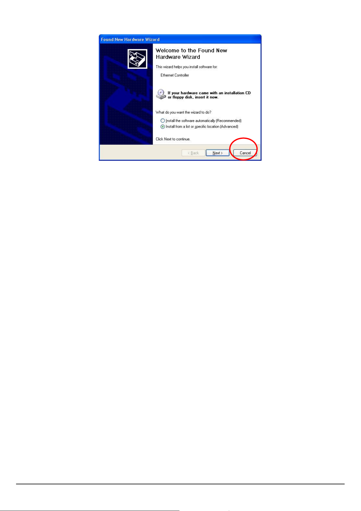
z The Windows "New Hardware" wizard will then prompt. Please click Cancel
6
Page 9

Installation Procedure for CardBus
You should install the supplied software BEFORE inserting the Wireless Adapter when using
Windows 2000 or XP.
When using Windows Vista, please insert the card first, and then run the software utility.
Note
The following installation was operated under Windows XP. (Procedures are
similar for Windows 2000.)
Note
If you have installed the Wireless PC Card driver & utility before, please uninstall
the old version first.
LED Indicator for PCI
Link
The Link LED indicator lighted green when the 11g Wireless LAN Adapter is connected to wireless
network successfully.
LED Indicator for CardBus
Link
The Link LED indicator lighted green when the 11g Wireless LAN Adapter is connected to wireless
network successfully.
ACT (Activity)
When the 11g Wireless LAN Adapter is transmitting or receiving data, the ACT LED indicator blinking
in green.
Page 10

Check the installation
The LEDs of the Wireless LAN Adapter are clearly visible and the status of the network link can be
seen instantly:
1. Once the device is plugged to the station’s CardBus/PCI slot, the LED of the Wireless LAN
Adapter will light up indicating a normal status.
2. When the device plugged to the station’s CardBus/PCI slot and the driver was installed, the ACT
will start alternate blinking; it means that the device is starting to scan the wireless devices near
the Wireless LAN Adapter.
3. While the Wireless LAN Adapter linked up and transmitting data to the Access Point or to other
Wireless LAN station, the Link LED will lighted green.
8
Page 11

Software Installation
This section will lead you to install the driver and utility of the Wireless LAN Adapter.
Windows 2000/XP/Vista Utility Installation
1. Insert the 11g Wireless LAN Adapter Utility CD into the computer and then the Auto-run screen
will appear. Alternatively, open a file browser and double click on the autorun.exe file located in
the CD directory.
2. Select model than Click “Utility” to install the driver and utility. Select “XP/2000” or “Vista”,
depending on your operating system, and the install wizard will begin installing the software.
Follow the install wizard instructions to complete the installation.
7
Page 12

3. Follow the Install Shield Wizard Instructions. Click “Next” to continue and finish it.
The installation program will help you to setup the Wireless LAN utility. Be noted that the Windows
XP and Vista have its own Wireless Utility; you can either use the utility of Windows XP/Vista
or the provided utility.
When the Wireless LAN Adapter utility is installed properly, you will see the icon on the Windows task
bar. The user can configure the wireless settings using the Wireless Adapter Configuration Utility.
Double-click the utility icon that appears in the taskbar
When the icon in the toolbar represents in full blue color then the signal strength has an excellent
performance with the AP, if it represents in half blue color then the signal strength has a fair
performance with the AP, and if the icon represents in low blue, then the signal strength has a worst
performance with the wireless station.
Excellent Wireless Signal Strength
Adequate Wireless Signal Strength
Low Wireless Signal Strength
Wireless Card inactive
8
Page 13

Windows Vista Wireless Utility Setting
Link Information
This is the default screen after launching the Utility program.
Status: Shows the associated BSSID, which can be used to identify the wireless access point.
SSID: Shows the current SSID, which must be the same on the wireless client and AP in order for
communication to be established.
Wireless Mode: Shows the current wireless mode used for wireless communication.
Encryption: Hoes the current encryption mode used on the wireless network.
TX Rate: Shows the current data rate used for transmitting.
Channel: Shows the current channel for communication.
Signal Strength of Percentage: Shows the wireless signal strength of the connection between the
Wireless LAN USB 2.0 Adapter with the Access Point.
TX/RX: Shows the statistics of data transfer, and the calculation is based on the number of packets
transmitted and received. It also shows the link quality of the Wireless LAN Adapter with the Access
Point when operation under Infrastructure mode.
9
Page 14

Configuration
This screen is where you set the basic wireless settings for the Wireless LAN Adapter.
Profile Name: The default name is the same as the SSID of the platform which you connected and
you can change the name you favor (the key length is limited 1~32 bits).
SSID: Service Set Identifier, which is a unique name shared among all client in a wireless network.
The SSID must be identical for client in the wireless network.
Wireless Mode: There are two modes available for selection
z Infrastructure –to establish wireless communication with the LAN and other wireless client
through the use of Access Points.
z Ad-Hoc – to establish point- to-point wireless communication directly with other wireless client
device.
10
Page 15

Authentication: The following options are available: Open System, Shared key, WPA-PSK, WPA2PSK, WPA EAP-TLS and WPA2 EPA-TLS.
Select Open System, Shared Key for WEP data encryption feature.
Open System and Shared Key require the users to set a WEP key to exchange data with other
wireless clients that have the same WEP key.
The following will only be activated when Open, Shared Key is enabled:
Default Key: select one of the 4 keys to use.
Network Key: choose the encryption way, either in HEX or ASCII formats, and enter the password in
the blank space.
Key Length: select 64 or 128 bits as the length of the keys.
Key Format: HEX or ASCII
WPA-PSK/ WPA2-PSK: This Passphrase must be the same on each computer that is connected to
the wireless network.
WPA/ WPA2: Please click the “Certificate” button. Then, please select the certificate that user wants
to use
Encryption: Select the encryption type for TKIP or AES encryption type.
Page 16

Site Survey
This screen allows the user to scan for available wireless networks (wireless clients and Access
Points). It also allows the user to establish wireless communications with an available wireless
network.
Available Network – displays the wireless networks (wireless clients and Access Points) that are
within range.
Select any one of the wireless networks by double-clicking on it or clicking on the “Connect” button.
Click the “Refresh” button to scan for available networks.
12
Page 17

Profile
Profile –The user can create and manage the created profiles for home, work or public areas. By
double-clicking on one of the created profile, the setting will adjust to the specific setting such as
SSID, channel, and encryption as saved by that particular profile.
Add: Adds a profile. The following screen will appear. The user can enter the necessary information
required for accessing Access Points or Wireless Router.
Remove: Deletes the selected profile
Edit: To view and change its settings of the profile.
Connect: The current connected profile information
Page 18

About
This screen displays information about the 11g Wireless LAN Adapter, such as the Driver and Utility
version. When a new version of the utility becomes available for upgrade, users will be able to
identify by version numbers.
14
Page 19

Windows XP/2000 Wireless Utility Setting
Link Information
The default page is as below after launching the Utility program.
Status: Shows the associated BSSID, which can be used to identify the wireless network.
SSID: Shows the current SSID, which must be the same on the wireless client and AP in order for
communication to be established.
Frequency: Shows the current frequency used for wireless network.
Wireless Mode: Shows the current wireless mode used for wireless communication.
Encryption: Shows the current encryption mode used for wireless network.
TxRate: Shows the current data rate used for transmitting.
Channel: Shows the current channel for communication.
Link Quality: Shows the link quality of the wireless LAN adapter with the Access Point when
operating under Infrastructure mode.
Signal Strength: Shows the wireless signal strength of the connection between the wireless LAN
adapter with the Access Point.
Page 20

Data Rate: Shows the statistics of data transfer, and the calculation is based on the number of
packets transmitted and received.
Configuration
This screen is where changes the basic wireless settings for the wireless LAN adapter with the
minimum amount of effort to implement a secure wireless network environment.
SSID: Service Set Identifier, which is a unique name shared among all clients and nodes in a
wireless network. The SSID must be identical for each clients and nodes in the wireless network.
Wireless Mode: There are two types available for selection
● Infrastructure: to establish wireless communication with LAN and other wireless clients
through the use of the Access Points.
● Ad-Hoc: to establish point-to-point wireless communication directly with other wireless client
devices such as wireless network PCI Adapter.
AdHoc Band: When using Wireless Mode for Ad-Hoc mode, select the AdHoc Band from drop
down list for 11b only, 11g only or Auto for both of 11b and 11g.
Channel: The channel range of 1 to 11 for North America (FCC) domain and 1 to 13 for European
(ETSI) domain and 1 to 14 for Japanese domain.
16
Page 21

WARNING: Country domain can't be choosing by end-user, because the incorrect region may be in
violation of applicable laws.
Power Mode: There are 3 modes to choose from.
• Continuous Access Mode (default) – the wireless LAN adapter is constantly operating with full
power. This mode consumes the most power.
• Maximum Power Save – the wireless LAN adapter consumes the least power. This mode only
operates when there is wireless network activity.
• Power Save – the wireless LAN adapter consumes moderate level of power.
Preamble: Select Long or Short Preamble type. Preamble is a sequence of bits transmitted at 1Mbps
that allows the PHY circuitry to reach steady-state demodulation and synchronization of bit clock and
frame start. Two different preambles and headers are defined: the mandatory supported Long
Preamble and header, which interoperate with the 1 Mbit/s and 2 Mbit/s DSSS specification (as
described in IEEE Std 802.11), and an optional Short Preamble and header (as described in IEEE
Std 802.11b). At the receiver, the Preamble and header are processed to aid in demodulation and
delivery of the PSDU. The Short Preamble and header may be used to minimize overhead and, thus,
maximize the network data throughput. However, the Short Preamble is supported only from the
IEEE 802.11b (High- Rate) standard and not from the original IEEE 802.11. That means that stations
using Short-Preamble cannot communicate with stations implementing the original version of the
protocol. Click “Apply” for the changes to take effect.
Support Band: There are two modes the user can select, including 11B and 11G. The default setting
is 11B and 11G are enabled, which is interoperable with both 11B and 11G devices.
Note: user must select one of 11B or 11G at least; otherwise the wireless connection will not function.
Page 22

Advanced
This screen is where you configure the Security settings for the 11g Wireless LAN Adapter.
Auth Mode: Select the authentication type from drop down list for Disable, Open System, Shared
Key, WPA, WPA-PSK, WPA2 and WPA2-PSK.
18
Page 23

Open System / Shared Key
WEP Key 1~4: choose the encryption way, either in HEX or ASCII formats, and enter the password
in the blank space.
Page 24

Key Length: select 64 or 128 bits as the length of the keys. If you select 64bit in Hex format, you
must type 10 values in the following range (0~F, hexadecimal), or 64bit in ASCII format, you must
type 5 values in the following range (0~9, A~Z and a~z Alphanumeric); If you select 128bit in Hex
format, you must type 26 values (0~F, hexadecimal), or 128bit in ASCII format, you must type 13
values in the following range (0~9, A~Z and a~z Alphanumeric).
Default Key: select one of the 4 keys to use.
Key Format: ASCII or HEX.
WPA-PSK / WPA2-PSK
If WPA-PSK or WPA2-PSK is selected, the above screen is shown. Please select the encryption type
from drop down menu and press Configuration button to configure the passphrase key.
Encryption: Select the encryption type for TKIP or AES encryption type.
20
Page 25

WPA / WPA2
Page 26

If WPA or WPA2 is selected, the above screen is shown. Please select the encryption type from drop
down menu and press Configuration button to configure parameters for the RADIUS server.
WARNING:WPA, WPA2 don’t support In Windows 98/ME .
Encryption: Select the encryption type for TKIP or AES encryption type.
Site Survey
This screen allows user to scan for available wireless networks (wireless clients and Access Points).
It also allows the user to establish wireless communications with an available wireless network.
Available Network – displays the wireless networks (wireless clients and Access Points) that are in
signal range.
Select any one of them to establish communications by simply
mouse double-click or click on the “Connect” button.
Click “Refresh” button to start scanning for available network again.
Profile – The user can create and manage the created profiles for
home, work or public areas. By double-clicking on one of the
22
Page 27

created profile, the setting will adjust to the specific setting such as SSID, channel, and WEP as
saved by that particular profile.
Add: Adds a profile. Then, the following screen would appear. User can enter the necessary
information required for accessing Access Points or Wireless Router.
Edit: To view and change its settings of the profile.
Remove: Deletes the selected profile
Connect: The current connected profile information.
Page 28

About
This screen displays information about the 11g Wireless LAN Adapter, such as the Driver and Utility
version. Users are able to identify by version numbers when a new version of the utility for upgraded.
24
Page 29

Technical Specifications
General
Radio Technology
Interface WNC-0301: 32-bit PCI bus; WPC-0301: 32-bit CardBus,
Data Transfer Rate 1, 2, 5.5, 6, 9, 11, 12, 18, 24, 36, 48, 54Mbps
Receiver Sensitivity
Transmit Power
Frequency Range
Modulation Schemes DBPSK/DQPSK/CCK/OFDM
Channels
IEEE 802.11b Direct Sequence Spread Spectrum (DSSS)
IEEE 802.11g Orthogonal Frequency Division Multiplexing (OFDM)
54Mbps: Typical -70dBm @ 10% PER (Packet Error Rate)
11Mbps: Typical -86dBm @ 8% PER (Packet Error Rate)
802.11b: 15±2dBm
802.11g: 13±2dBm
2412 ~ 2484 MHz ISM band (channels 1 ~ 14)
2400~2483.5MHz ISM band (channels 1 ~ 11)
1~11 channels (FCC), 1~13 channels (ETSI),
1~14 channels (MKK-Japan)
Media Access
Protocol
Security 64/128-bits WEP Encryption, WPA-PSK, WPA2-PSK, WPA, WPA2
Diagnostic LED
Antenna
CSMA/CA with ACK
CardBus Adapter: Link, ACT
PCI Card: Link
CardBus Adapter: Integrated printed dual diversity antennas
PCI Card: 2dBi dipole antenna
Physical and Environmental
Driver Support Windows 2000, Windows XP, Windows Vista
Temperature Operating: 0° ~ 40° C, Storage: -10° ~ 70° C
Humidity 10% ~ 95% RH, no condensation
Dimensions PC Card:, 115 x 54 x 8.7 mm, PCI Adapter: 13 x 121 x 21.6
Certifications FCC Part 15.247 for US, ETS 300 328 for Europe,
25
 Loading...