

Page 1
LevelOne
WHG-1000
300Mbps Wireless PoE Hotspot Gateway
User Manual
H/W Ver 2.0
2012/11/08
Page 2

tents
Chapter 1. Before You Start............................................................................................... 1
1.1 Preface ........................................................................................................................................ 1
1.2 Package Contents ....................................................................................................................... 1
Chapter 2. System Overview ............................................................................................. 2
2.1 Introduction of WHG-1000 .......................................................................................................... 2
2.2 System Concept .......................................................................................................................... 2
2.3 Specification ................................................................................................................................ 3
Chapter 3. Base Installations ............................................................................................ 9
3.1 Installations ................................................................................................................................. 9
3.1.1 System Requirements ......................................................................................................... 9
3.1.2 Panel Function Descriptions ............................................................................................... 9
3.1.3 Hardware Installation ......................................................................................................... 11
3.2 Software Configuration ............................................................................................................. 12
3.2.1 Getting Start ...................................................................................................................... 12
3.2.2 Quick Configuration .......................................................................................................... 14
3.2.3 Access Internet ................................................................................................................. 19
Chapter 4. Web Interface Configuration ........................................................................ 20
4.1 Connect WHG-1000 to the external Netw ork ......................................................................... 21
4.1.1 Network Requirement ....................................................................................................... 21
4.1.2 Configure WAN Port .......................................................................................................... 21
4.1.3 Configure WAN Traffic ...................................................................................................... 24
4.1.4 Configure Dynamic DNS ................................................................................................... 26
4.1.5 Configure Local(LAN/VLA N) Net w ork .............................................................................. 27
4.2 Create Your Wireless Networ k .................................................................................................. 32
4.2.1 Configure Wireless General Setup ................................................................................... 32
4.2.2 Configure Wireless Advanced Setup ................................................................................ 34
4.2.3 Create Virtual AP............................................................................................................... 37
4.2.3.1 Configure Virtual AP .................................................................................................. 40
4.2.3.2 Block Wireless Clients .............................................................................................. 45
4.2.3.3 Monitor Associated Wireless Clients ......................................................................... 46
4.3 Expand Your Wireless Network ................................................................................................ 47
4.3.1 Create WDS Link .............................................................................................................. 47
4.3.2 View WDS Link Status .................................................................................................... 48
4.4 Manage the System .................................................................................................................. 49
4.4.1 Configure System Time ..................................................................................................... 49
4.4.2 Configure Management .................................................................................................... 50
4.4.3 Configure SNMP ............................................................................................................... 53
4.4.4 Backup / Restore and Reset to Fa ct or y ............................................................................ 54
4.4.5 Firmware Upgrade ............................................................................................................ 55
Page 3

4.4.6 Network Utility ................................................................................................................... 56
4.4.7 Format Database .............................................................................................................. 57
4.4.8 Reboot ............................................................................................................................... 58
4.5 Access To External Network With Servic e Domain .................................................................. 59
4.5.1 Configure Service Domain ................................................................................................ 60
4.5.2 Configure Authentication ................................................................................................... 64
4.5.2.1 Authentication Management ..................................................................................... 64
4.5.2.2 Configure Pregenerated Tickets ............................................................................... 65
4.5.2.3 Configure On-Demand .............................................................................................. 72
4.5.2.3.1 Create Billing Plans ........................................................................................... 73
4.5.2.3.2 Create On-Demand Users ................................................................................ 75
4.5.2.3.3 Configure External Pay m ent G at eway.............................................................. 79
4.5.2.3.4 Configure Thermal Printer ................................................................................. 82
4.5.2.3.5 Billing Plan Report ............................................................................................. 87
4.5.2.3.6 Ticket Customization ......................................................................................... 89
4.5.2.4 Configure Local RADIUS Accounts .......................................................................... 90
4.5.2.5 Configure Remote RADI US Server .......................................................................... 93
4.5.2.6 Configure LDAP Server ............................................................................................ 94
4.5.3 Configure Privilege List ..................................................................................................... 95
4.5.4 Configure Walled Garden ................................................................................................. 96
4.5.5 Configure Blacklist ............................................................................................................ 98
4.5.6 Configure Notification ........................................................................................................ 99
4.5.7 Monitor Online Users ...................................................................................................... 104
4.5.8 Log Information ............................................................................................................... 105
4.6 Restrain the Users and Sharing Your Internal Service ........................................................... 108
4.6.1 Configure Time Policy ..................................................................................................... 108
4.6.2 IP Filter ............................................................................................................................ 109
4.6.3 MAC Filter ........................................................................................................................ 110
4.6.4 Virtual Server (Port / I P Forwarding) ................................................................................. 111
4.6.5 DMZ .................................................................................................................................. 112
4.7 Observer the Status ................................................................................................................. 113
4.7.1 Overview .......................................................................................................................... 113
4.7.2 Extra Info .......................................................................................................................... 114
4.7.3 Event Log ......................................................................................................................... 117
Appendix A. Web GUI valid Characters ................................................................... 118
Appendix B. System Manager Privileges ................................................................ 123
Appendix C. Create PayPal Business Account ....................................................... 124
Appendix D. Examples of Making Payments for End Users .................................. 128
Appendix E. Issue Refund for PayPal ...................................................................... 131
Page 4

Chapter 1. Before You Start
Package Contents
• Ground Cable x 1
1.1 Preface
The WHG-1000 is the mo st economical yet feature-rich Wi r el ess Hotspot Gateway, targeting mini-size
stores who want to provide s m al l, s in gle-point wireless Internet acc ess ser vice. WHG-1000 is a perfect
choice for beginners to ru n hotspot businesses. It does not c ost a fortune to buy a pile of equipment,
nor does it take the skills of an expert to glue multiple appl ications out of multiple freeware. Featurepacked for hotsp ot oper ation, WHG-1000 comes with built-in 802.11n/b/g access point, web server
and web pages for clients to login, easy logo-loading for branding a hotspot store, si m ple
user/visitor account m anagement tool, p ayment plans, PayPal credit card gateway, traffic logs,
IP sharing and etc.
1.2 Package Contents
• WHG-1000 x 1
• Quick Installation G uide x 1
• CD-ROM (with User Manual and QI G ) x 1
• Console Cable x 1
• Ethernet Cable x 1
• Power Adapter DC12V 1A x 1
• Antenna x 2
It is highly recommended to use all the supplies in the package instead of substituting any components by
other suppliers to guarantee best performance.
Page 5
Chapter 2. System Overv iew
2.1 Introduction of WHG-1000
The WHG-1000 – Wireless Hots pot Controller , built-in Wifi-N technology with data rate up to 300 Mbps,
applies to public access n etwork such as WiFi-Hotspot , network management guest access, hospitality
deployments – whi ch r equires reliability, efficiency, and security. I t combines an IP Router /Firewal l,
Multi-WAN/ QoS enforcement and Access Controller for use in wireless hotspot environme nts. One
single WHG-1000 can serv e Suggest 100 simultaneous users, takes control over authent ication,
authorization, accounti ng and routing to the Internet as w ell as to t he operating central. Built -in AAA
system allows hotsp ot owners set up public access serv ices w ithout extra RADIUS server.
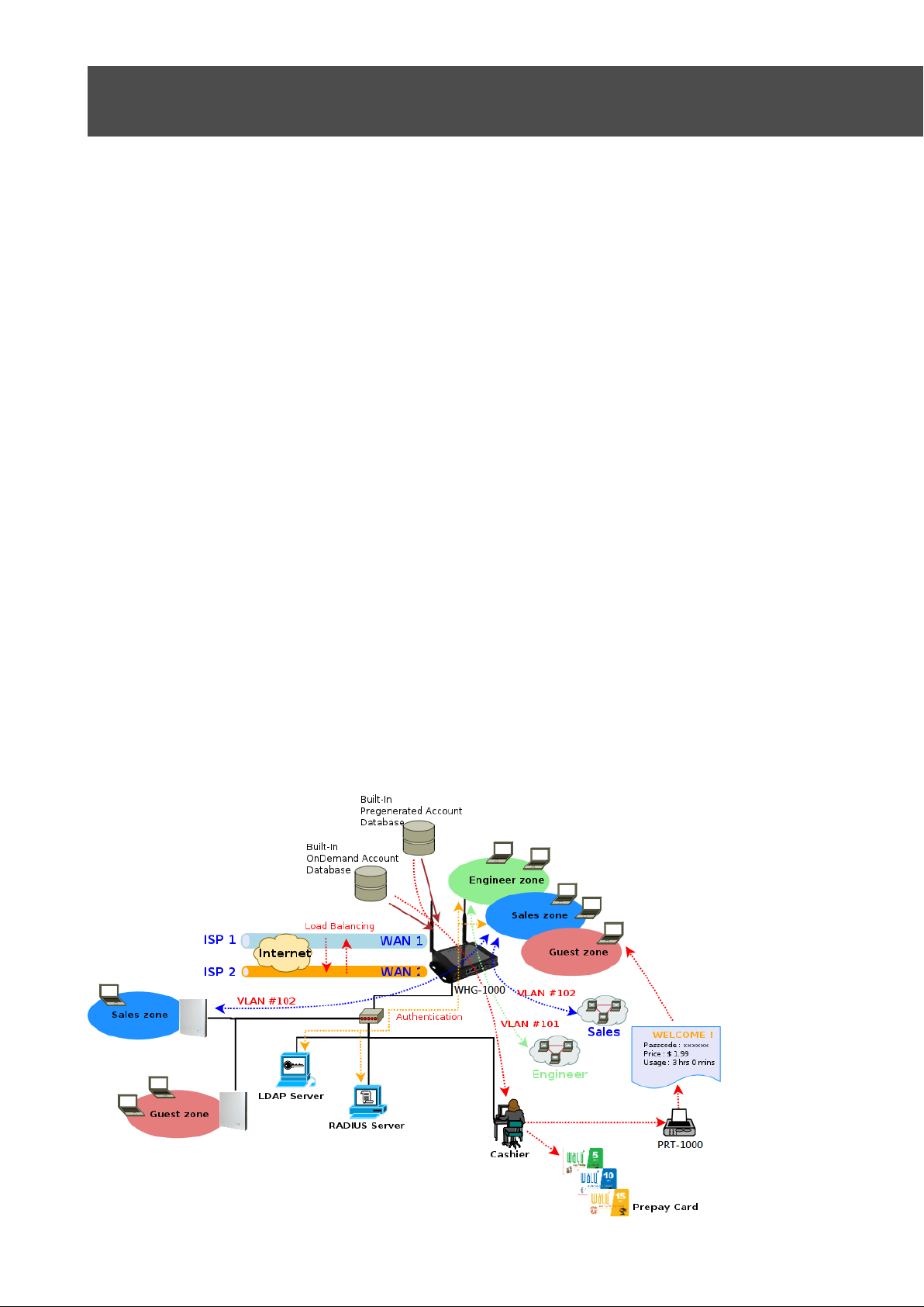
2.2 System Concept
WHG-1000 Wireless Hotspot Controller provides au t hentication, authorization and ac counting for a
wired/or wireless networks. Hotspot technology allows Internet providers to offer Internet access to
customers, while apply ing certain Internet use rules and limitation. It is conv enient f or I nt er net c af es,
hotels, airports, sc hools and universities. The I nt er net provider gets complet e tracking records of per
customer time spent on the net work, data amount sent/ r eceived, real-time accounting a nd more.
To begin browsing, a client must go through a registration process with t he provider, then enter a
Passcode/Username of a cc ess t icket in a browser Login window t hat appears on the attempt to open a
webpage. Hotspot technology proposes providers to establish and administrate a user database, which
can be useful for enterpris e such as airports, hotels or universities that offer wir eless or Ethernet
Internet connectivity t o em ploy ees , st udents, guests or ot her gr oups of users.
Page 6

WHG-1000 300Mbps Wireless PoE Hotspot Gateway
2.3 Specification
Network
Support NAT or Router Mode
Support static IP, Dynamic IP(DHCP Client ), PPPoE and PPTP on WAN connection
DHCP Server Per VLAN; Multiple DHCP Networks
802.3 Bridging
Proxy DNS/Dynamic DNS
Support NAT
IP/Port destination redirection
DMZ server mapping
Virtual server ma ppi ng
Built-in with DHCP server
NTP Client
Binding VLA N w it h Ethernet and Wireless interfa ce
H.323, SIP Pass-through
User's Manual
Support MAC Filter
Support IP Filter
Support URL Filter
Support Walled garden (free sur f in g zone)
Support MAC-address and IP-address pass through
IP Plug a nd Play (IP PnP)
User Management
Suggest 10 0 si m ultaneous authenticati on users
Max 3066 Accounts
Support Pregenerated Users, On-Dem and Users and Local RADIUS Accounts.
Users Session Manage m ent
Configurabl e us er Black list (with Time-based control)
Allows MAC a ddr ess and user identity binding for local user authentication
SSL protected login port al page
Login Sess ion idl e t ime out setting
Session and a ccount expiration control
User Log and t r affic statistic notificati on via automatically email service
Login time frame control
Session limit
Real-Time Online Users Traffic S tatistic Reporting
Support local account roaming
6
Page 7

WHG-1000 300Mbps Wireless PoE Hotspot Gateway
User's Manual
Seamless Mobility : User-centric networking manages wired and wireless users as they roam between
ports or wireless APs
Multiple Service Domain
The network is divided into maximum 8 group, each defined by a pair of VLAN tag and ESSID
Each Domain has its own (1) login portal page (2) authentication options (3) LAN interface IP
address range (4) Session number limit control (5) Traffic shaping (6) IP Plug and Play (IP PnP)
(7) Multiple Authentication
Enable DH CP or not, and DHCP address range
Enable authentication or not
Enable Guest ser vice or not
Types of authentication options (Local RADIU S, Re mote RADIUS, LDAP, On-Demand and Pregenerated)
Bandwidth (Distribution or Individua l)
Scheduling aut hentication service control on different Service D omain
Authentication
Authentication: single sign-on (SSO) client w it h aut hentication integrated into t he local authentication
environment through loc al /domain, LDAP, RADIUS, MAC authentication, and 802.1x
Customizable Login and Logout Portal Pages
Customizable Advertisement Links on Login Porta l Page
User authentication with UAM (Universal Access M ethod), 802.1x /EAPoLAN ,M AC address
Allow MAC ad dres s and users identity binding for local user authentication
Support Multiple Login service on one Accounts
Each group (role) may get different network policies in different Service Domain
Max simult aneous user session (TCP/UDP) limit
Configurabl e us er black list
Export/Import local users list to/from a text file
Web-based Captive Portal for SSL br ow ser-based authenticatio n
Authenticat ion Type
IEEE802.1X(EAP, EAP/TLS, EAP/TTLS, EA P/GTC, EAP/M D5, EAP/MSCHAP-V2)
RFC2865 RADIUS Authentication
RFC3579 RADIUS Su pport for EAP
RFC3748 Extensible Authentication Protocol
MAC Address authentication
Web-based captive portal authentication
7
Page 8

WHG-1000 300Mbps Wireless PoE Hotspot Gateway
User's Manual
Accounting :
Provides bi lling plans for Pregenerated accounts
Provides bi lling plans for On-Demand accounts
Enables ses sion expiration control for both Pregener ated ticket s and On-Demand accounts by Time(Hours)
and Data Volume(MB)
Detai led per-user traffic histor y based on time and data volu me for bot h Pregenerated tickets an d O n-
Demand accounts
Support Loca l R ADIUS, Pregenerated, On-Demand and external RADI US ser v er
Contai n 10 configurable billing plans for O n-Demand accounts
Support credit card billing system by Pap al
Support automatic email network traffic history
Security
Layer 2 User Isolation
Blocks client t o cli ent di scovery within a specified V LAN
Setting for TKIP/CCMP/AES key ’s refreshing periodically
Hidden ESSID support
Setting for “ D eny Any “ connect ion request
MAC Address Filtering (MAC ACL)
Support Data Encryption : WEP(64/12 8-bit), WAP, WAP2
Support v ar ious aut hentic ation methods : WP A-PSK, WPA-RADIUS, IEEE802.1X
No. Of Register ed RADIUS Servers : 2
Support VPN pass-through
Encryptio n Type
WEP: 64, 128 and 152 bit
WAP-TKIP , WPA-PSK –TKIP, WPA-AES, WPS-PSK-AES
WAP2/8 02. 11i :WPA2-AES, WAP2-PSK-AES, WAP2-TKIP, WPA-PSK-TKIP
Secure Socket Layer (SSL ) and TLS : RC4 128-bit and RSA1024-bit and 2048-bit
Dual WAN
Load Balancing
Outbound Fault Tolerance
Outbound load balance
Multiple Domain Support
By Traffic
Bandwidth Management by indiv idu al and distribution on diff er ent net work(Service Domain)
WA N Con necti on Detecti on
8
Page 9

WHG-1000 300Mbps Wireless PoE Hotspot Gateway
QoS Enforcement
Packet classification via DSCP (Differentiated Services code Point )
T r affic Statistics
Diff/TOS
IEEE 802.1Q Tag VLAN priority control
IEEE 802.1 1e WMM
Automatic mapping of WMM priorities to 802.1p and IP DSCP
Upload and Dow nload Traffic M anagement
Wireless
Transmission power control : 7 Levels
Channel se lection : Manual or Auto
No. of associ at ed clients per AP : 32
Setting for ma x no associated clients : Yes
No. of BBSID (Virtual AP) : 8
User's Manual
No. of Max. WDS setting : 4
Preamble set t ing : Short / Long
Setting for 802.11b/g/n mix, 802.11b only or 802.11 b/g only or 802.11n only
Setting for transmission speed
IEEE802. 11f IAPP ( Inter Access Point Protocol ), hand over users to an ot her AP
IEEE802. 11i Preauth (PMSKA Cache)
IEEE802. 11d Multi country roaming
Automatic channel assignment
Coordinated Access ensures optimal perfor m ance of nearby APs on the same channel
Secure wireless bridge connects access points without wire
Monitoring a nd r eporting
System A dmini strati on
Intuitive Web Management Int er face
Three administrator accounts
Provide cust omizable login and logout portal page
CLI access ( Remote Management) via Telnet and SSH
Remote firmware upgrade (via Web)
Utilities to bac k up and restore the system configuration
Remote Link Test – Display connect statistics
Full Statistics and Status Reporting
Real time traffic monitor
9
Page 10

WHG-1000 300Mbps Wireless PoE Hotspot Gateway
Ping Watc hdog
WHG-1000 Hardware Specifications
Base Platform
AR7240+AR9283
CPU Clock Spe e d
400 MHz
Wireless Radio
802.11bgn
Serial Port
1 (DB-9)
USB Port (Optional)
1 (Optional 3G interface r adio with major brands – ODM only)
Reset Switch Built-in
Push-button momentary contact switch
RF Channel Scan Hardware
Button
Hardware Push-button to s can for a better channel to use
Stan dar ds Co nform a nc e
IEEE 802.3 / IEEE 802.3u
Ethernet Configur at ion
10/100BASE-TX auto-n egotiation Ethernet port x 3 (RJ-4 5 connector)
Auto Fail over
SDRAM
On board : 64 Mbytes
Flash
On board : 16 Mbytes
Built-In LED Indicators
1x Power , 2 x WAN ,1x LAN , 1x Status, 1x System, 1x Printer
T r affic history report via email to administrator
Users’ session log can be sent by external Syslog Server or E-mail
Even Syslog
SNMP v1, v2c,v3
SNMP Traps to a list of IP Address
Support MI B-II
S p annin g T ree Protocol
NTP Time Synchroniz ation
Customizable Time D is play Format for System
Administrativ e Access : HTTP / HTTPS
User's Manual
WAN * 2
LAN * 1
Auto MDI/MDI-X enabled , IEEE802.3af Power Over Ethernet Compatible ,
10
Page 11

WHG-1000 300Mbps Wireless PoE Hotspot Gateway
User's Manual
Wireless Specifications
Network Sta ndar ds
Conformance
IEEE802.11 b /g /n compliant
Data T r ansf er Rate
IEEE802.11n : 300 (auto sensing)
Frequency Range
2.457 ~ 2.472 GHz (Franc e)
Media Access Protocol
CSMA / CA with ACK
Modulation Metho d
Operating Cha nnels
802.11b/g/n : 11 for FCC,14 for Japan,13 for Europe, 2 for Sp ain, 4 for France
RF Output Power
100mW
Transmit Power V ariatio n
802.11g/n : Up to 16 dBm
802.11b : up to 18 dBm
Frequency Response fl atness
±1dB over operating rang e
Receiver Sensitiv i ty
802.11b/g /n
-90dBm@1Mbps, -86dBm@6Mbps,-84dBm@11Mbps,-69dBm@54Mbps
Environmental & Mechanical Characteristics
Operating Temperature
-20 °C ~ 50 °C
Storage Temperature
-20 °C ~ 60 °C
Operating Humidity
10% to 80% Non-Condensing
Storage Humidity
5% to 90% Non-Condensing
Antenna Conne c t or
SMA-Type Connector
Power Supply
110 – 220V AC Power ; 12 VDC, 1A input.
Support 802.3af Compl ian t , Power Over Ethernet (48V/0.3 A)
Unit Dimensions
205 x 125 x 35 (mm) (Width x Dept h x He ight)
Unit Weight
600g
Form Factor
Wall Mountable , Metal case co mp li ant w it h I P50 standard
Certifications
FCC,CE, IP50,ROHS compliant
IEEE802.11b:1 / 2 / 5.5 / 11Mbps (auto sens ing)
IEEE802.11g:6 / 9 / 12 / 18 / 24 / 36 / 48 / 54(auto sensing)
IEEE802.11b/g:
2.412 ~ 2.462GHz (USA)
2.412 ~ 2.484GHz (Japan)
2.412 ~ 2.472 GHz (Euro pe E TSI )
2.457 ~ 2.462 GHz (Spain)
IEEE802.11b:DSSS (DBPK,DQPSK,CCK)
IEEE802.11g/n:OFDM(64-QAM,16-QAM,QPSK,BPSK)
11
Page 12
WHG-1000 300Mbps Wireless PoE Hotspot Gateway
Chapter 3. Base Installations
3.1 Installations
3.1.1 System Requirements
Standard 10/100Base T including f iv e net work cables with RJ-45 connector s
All PCs need to install the TCP/IP network protocol
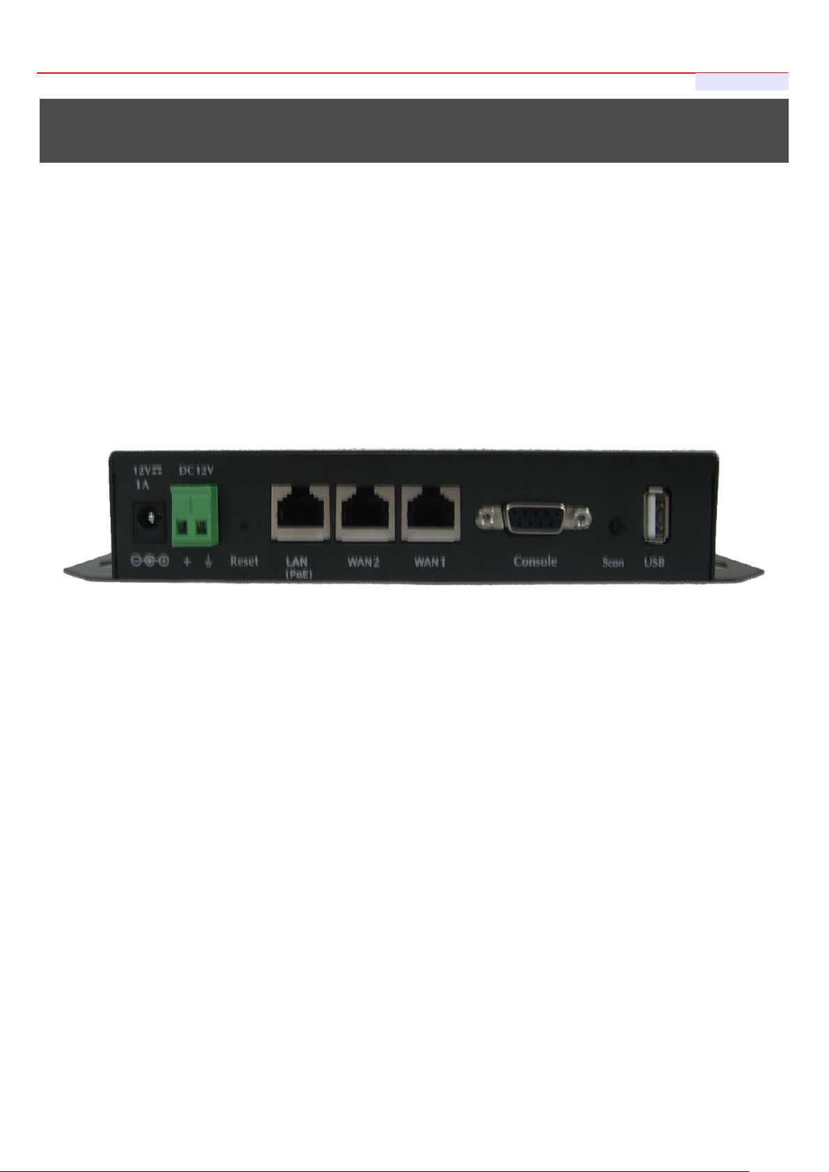
3.1.2 Panel Function Descriptions
Front Panel
User's Manual
1. Power SOCKET (12V DC) : Attach the power socket here.
2. Reset : Press the Reset button once to restart t he system, The LED except Power indicator will be of f
before restarting.
3. LAN(POE) : Clients devices connect to WHG-1000 via LAN ports
4. WAN1/WAN2 : Two WAN ports are availab le on the system.
5. Console : The serial RS-232 DB9 cable attaches here.
6. Scan Button :
Press and hold t he Scan button for 3 seconds unt il STATUS LED FLASH and release to Scan New AP's
Channel.
Press and hold t he Scan button for more than 10 seconds until SYSTEM LED FLASH to reset the
system to default configurations.
7. USB : (option)
12
Page 13
WHG-1000 300Mbps Wireless PoE Hotspot Gateway
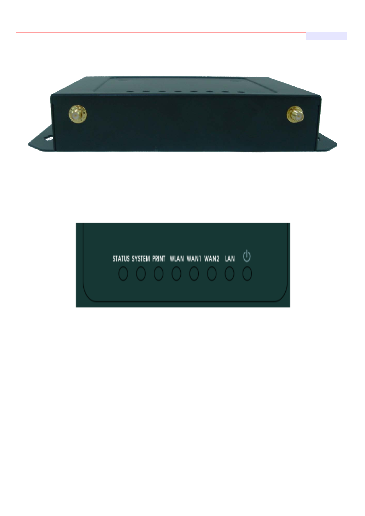
Rear Panel
1. WHG-1000 supports 1 RF interface with 2 SMA connectors for Antenna connection.
LED Panel
User's Manual
1. Power : LED ON indicates power on, OFF indicates power off.
2. WAN1/WAN2/LAN : LED ON indicates connection, OFF indicates disconnection, FLASH indicates packets
transmitting.
3. WLAN : LED ON indicates Wireless ready.
4. PRINT : LED ON indicatesDSA-1000 ready.
5. SYSTEM : LED ON/FLASH indicates Flash busy, OFF indicates Flash Idle
6. STATUS : LED ON indicates System up, OFF indicates down, FLASH indicates Scan button activated.
13
Page 14

WHG-1000 300Mbps Wireless PoE Hotspot Gateway
User's Manual
package. Using a different power adapter
3.1.3 Hardware Installation
Please follow the steps mentioned below to install the hardware of WHG-1000
1. Place the WHG-1000 at a best location.
The best location for WHG-1000 is usually at t he center of your wireless network.
2. Connect WHG-1000 to your outbound networ k device.
Connect one end of the Ethernet cable to the WAN1/WAN2 port of WHG-1000 on the front panel. On your
environment, connect t he ot her end of the cable to the external Inter net . The WAN1/WAN2 LED indicator should be
ON to indicate a proper co nnect i on.
3. Connect WHG-1000 to your network device.
Connect one end of the Ethernet c able to LAN port of WHG-1000 on the front panel. Connect the other end of cable
to a PC for configuring the system. The LAN LED indicator s hould be ON to indicate a proper connection.
4. There are two ways to supply power over to WHG-1000
Connect the DC power ad apt er t o t he WHG-1000 power socket on th e front panel.
Please only use the powe r adapt er supplied with the WHG-1000
may damage this system
WHG-1000 is capable of tr ansmitting DC current via its LAN(PoE) port. Connect an IEEE 802.3af-
compliant PSE device, e. g. A PoE Switch, to the LAN(PoE) port of WHG-1000 w it h t he Et her net cable.
Now, t he har dware installation is completed.
To double verify the wired connection between WHG-1000 and your switch/rou t er / hub, please check the
LED status indicat ion o f t hese network devices.
14
Page 15

WHG-1000 300Mbps Wireless PoE Hotspot Gateway
User's Manual
If you can't get the login screen, you may have incorrectly set your PC to obtain an IP ad dr ess
Please use default IP address such as 192.168.2.xx in y our net work and then try it again.
3.2 Software Configuration
3.2.1 Getting Start
Step :
1. Once the hardware installation is don e, set DHCP in TCP/IP of the administrator's P C to get an I P address
automatically. Connect the PC to the LAN(PoE) port of WHG-1000. An IP address will be assigned to t he
PC automatically via the WHG-1000.
2. Launch a web browser to access the web GUI o f WHG-1000 by ent er ing “http://192.168.2.254” in t he
address field.
3. The following Administ r at or Login Page will appear. Enter “root” in the Username field, and “default” in the
Password field. Click OK button to login.
automatically from LAN port or the IP address used does not have the same subnet as the URL.
15
Page 16
WHG-1000 300Mbps Wireless PoE Hotspot Gateway
User's Manual
You can login as root, admin or operator. The default username and password as follows.
Root : The administrat or can access all area of the WHG-1000
Username : root
Password : default
admin : The admin can a ccess the area under Service Domain, Wireless and Advanced setting (Please see
Appendix B.)
Username : admin
Password : admin
operator : The operator only can access the area of On-Demand authentication to create, edit and print out
the new On-Demand user acc ounts. (Please see Appendix B.)
Username : operator
Password : 1234
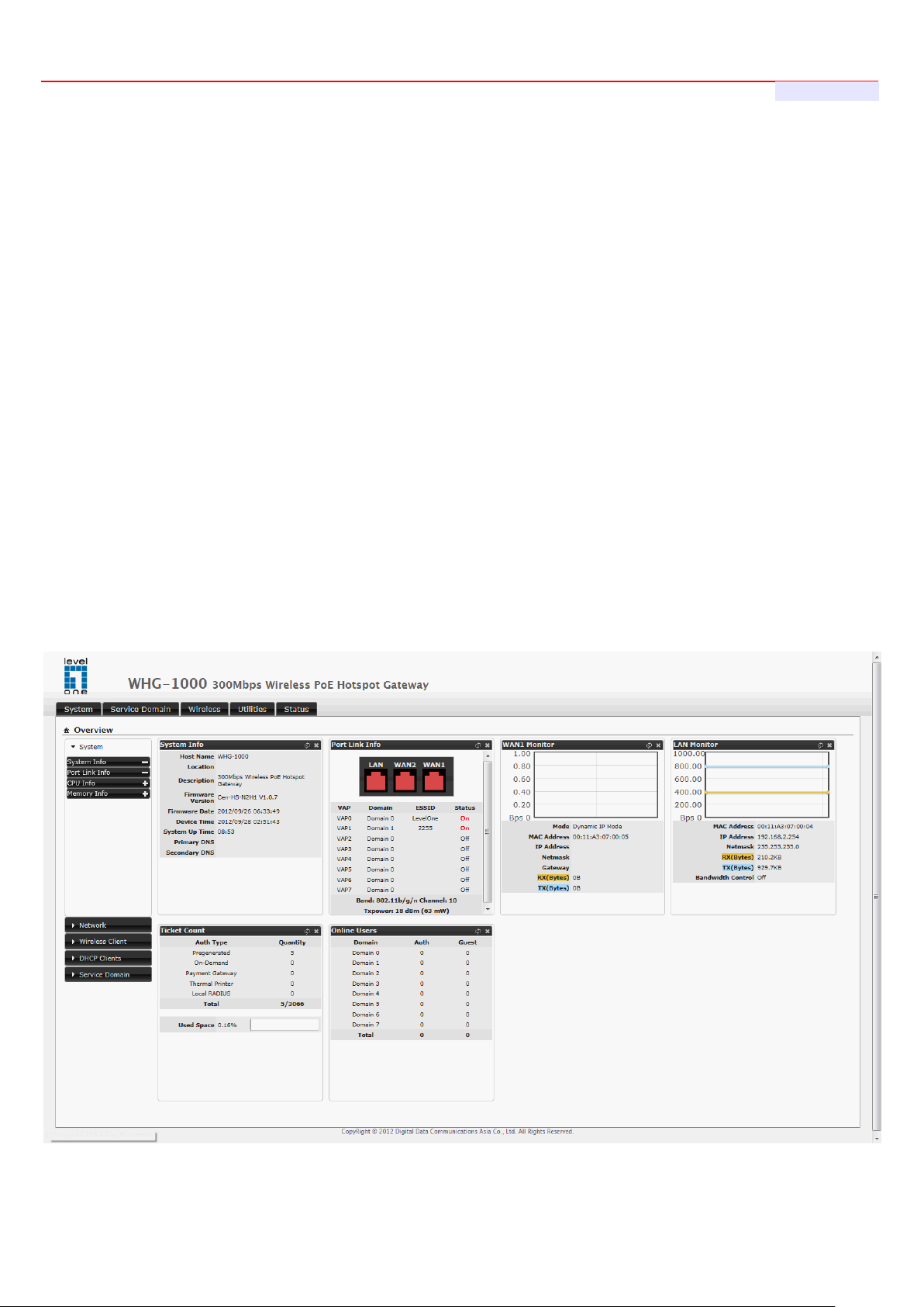
4. After a successful login, the “Home Page” will appear on the screen.
16
Page 17
WHG-1000 300Mbps Wireless PoE Hotspot Gateway
User's Manual
3.2.2 Quick Configuration
WHG-1000 provides wireless an d wired network service with authentication required for clients in Service Domain.
Clients in the each Service Domain are isolated with each other. WHG-1000 supports 8 Serv ice Domains, Domain-0
to Domain-7. Administrator can select authentication type on each Service Domain. If Authentication Re quire d is
enabled, the clients are r equired to get authenticated successfully before access the Inter net .
Configuration Steps :
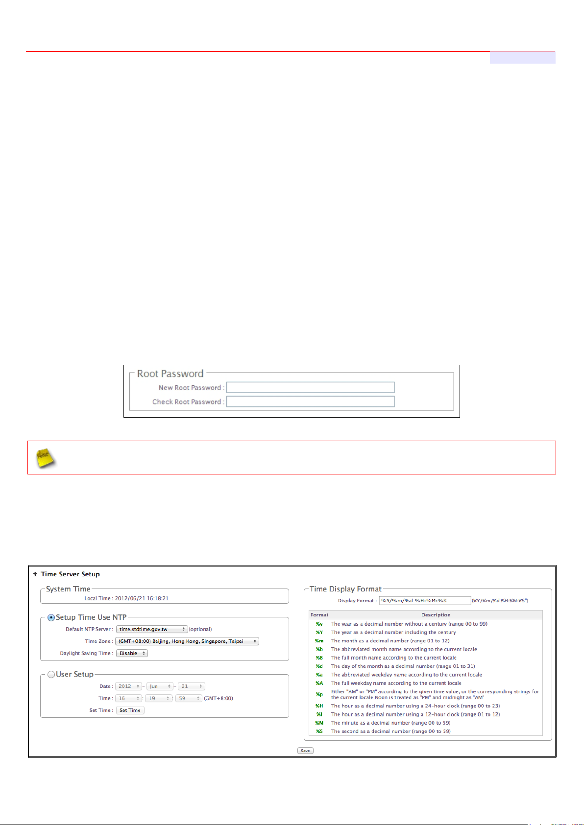
Step 1 : Change Root's Password
Click System → Management, the Management Setup page will ap pear.
Enter a New Root Password for the Root account ad retype in t he C heck Root Password field. (4-30
alphanumeric and specif ic char acters; not support Space)
Click Save button.
For security concern, it is strongly r ecommended to change the Root p assword.
Step 2 : Choose System's Time Zone
Click System → Time Server, the Time Server Setup page will appear.
Select the appropriate set t ing a nd c l ick Save button.
17
Page 18

WHG-1000 300Mbps Wireless PoE Hotspot Gateway
User's Manual
Before Hotspot service active, make sure the Local Time is correctly.
Step 3 : Select Connection Type for WAN1 Port and Set DNS Server
Click System → WAN, the WAN Setup page will appear.
Select the appropriate C onnection Type for WAN1 port, there are four types of WAN1 conne ctions to be
selected from: Static IP, Dynamic IP, PPPoE Client and PPTP Client.
Enter the IP Address of a DNS Server provided by your ISP(Int er net Service Provider). Contact the ISP if the
DNS IP Address is unknown.
Click Save button.
Step 4 : Configure Wireless General Settings
Click Wireless → General Setup, the Wireless General Setup p age will appear.
Select desired wireless Band, Channel.
Click Save button
18
Page 19

WHG-1000 300Mbps Wireless PoE Hotspot Gateway
Step 5 : Set Virtual AP and Select Au thentication Type for Service Domain
Click Service Domain, the Service Domain Setup page will a ppear.
Double-click AP0 Icon, the VAP0 Setup page will appear.
User's Manual
Select desired wireless ESSID and related settings.
Click Tool Icon on Domain0 window, the Service Domain0 Setup page will appear. For each Service
Domain(by default, authentication type is none), authentication type can be selected in Pregenerated Ticket,
On-Demand, Local RADIUS, Remote RADIUS Server and LDAP Server, and select one aut hentication
type for Default Auth Type. Below depicts an example for Local RADIUS.
19
Page 20

WHG-1000 300Mbps Wireless PoE Hotspot Gateway
User's Manual
Select Local RADIUS for Domain0's Authenticat ion Type.
Enter the Redirect URL that user s should be initially directed to when successfully authenticated to the
network.
Configure related settings for the selected Auth Type.
Click Save button.
20
Page 21

WHG-1000 300Mbps Wireless PoE Hotspot Gateway
Step 6 : Add Local RADIUS Accounts
Click Service D om ain → Authentication → Local RADIUS Accounts, the Local RADI U S Accounts
Management page will appear .
User's Manual
A new account can be added into the Local RA DIUS Database. To add a account here, enter the
Username(e.g. test1), Pass w or d( e. g. 11111), MAC Address(optional, to specify the valid MAC addr ess of this
account) and Description.
More accounts can be added by clicking the Save button.
Step 7 : Restart WHG-1000
Click Reboot, the Reboot page wil l app ear
Click Reboot button to start t he r estarting process.
Please don't interrupt the system during the restarti ng pr ocess.
When the “Home Page” appears, it means the rest art process is now completed.
21
Page 22

WHG-1000 300Mbps Wireless PoE Hotspot Gateway
User's Manual
3.2.3 Access Internet
To verify whether the configuration of the new Local RADIUS accounts cr eated via the Quick Configuration has
been completed successfully :
Step :
1. Connect a client device (e.g. Notebook) wit h w ireless interface to scan the configured ESSID of WHG-1000
(e.g. AP00) and get associated with this ESSID.
2. The client device will obtain an IP address automatically via D H CP from WHG-1000. Open a web browser
on a client device, access any URL, and then the Domain1 User Login Pa ge will appear.
3. Enter the Username and Password of a Local RADIUS account prev io usly generated via Quick
Configuration (e.g. “test1” as the Username and “11111” as the Password); then Click Login button.
Congratulation !
The T i mer page will appear after a client has successful ly logged into WHG-1000 and has been authenticated by
the system. Now, you are connected the network and Internet!
22
Page 23

WHG-1000 300Mbps Wireless PoE Hotspot Gateway
User's Manual
OPTION
System
Service Domain
Wireless
Advanced
Utilities
Status
WAN
Service Domain
General Setup
DMZ
Profile Setting
Overview
WAN T raf fic
Authentication
Advanced Setup
IP Filter
Firmware Upgrade
Extra Info
LAN/VLAN
Privilege List
Virtual AP Setup
MAC Filter
Network Util ity
Event Log
DDNS
Walled Garden
Associated Clients
Virtual Server
Format Database
Management
Notification
WDS Status
Time Policy
Reboot
Time Server
Online Users
SNMP
Log Info
After finishing the conf iguration of the settings, please click Save button and p ay attention to see if a
settings to take effect. Al l online users will be disconnected during restart.
Chapter 4. Web Interface Configuration
When Hotspot mod e is ac tivated, the system can be configured as a Wireless Hotspot Gateway. This section
provides information in configuring the Hotspot mod e with graphical illustrations. WHG-1000 provides functions as
stated below where they can be configured via a user-frie ndly web based interface.
Function
Reboot
message appears on the screen. If such message appear s, s ystem must be restarted t o allow the
23
Page 24

WHG-1000 300Mbps Wireless PoE Hotspot Gateway
User's Manual
4.1 Connect WHG-1000 to the external Network
4.1.1 Network Requirement
Basically, in general network environment, the main r ole of WHG-1000 is a Gatew ay. It manages all the network
from internal network to Int er net .
Then, the first step is to prepar e an Internet connection from your I SP and connect it to the WAN or WAN2 port of
WHG-1000.
4.1.2 Configure WAN Port
Here is instruction for how to setup the WAN. There are two WAN port can selected and configured. The connection
types for each WAN port : Static IP, Dynamic IP, PPPoE and PPTP, Please click on System -> WAN and follow the
below setting.
Static IP : The administ r at or can manually setup the W A N I P address when st atic IP is available/ preferred.
IP Address : The IP address of the WAN port.
IP Netmask : The Subnet mask of the WAN port.
IP Gateway : The IP address of the host router which resides on the external network and provides the
point of connection to the next hop t owards the Internet. This can be a DSL modem, C able modem, or a
WISP gateway router. WHG-1000 will direct all the packets to the gateway if the destination host is not
within the local network.
Gateway IP address should be from the same ad dr ess space (on the same net work segment) as the WHG1000's external network interface.
24
Page 25

WHG-1000 300Mbps Wireless PoE Hotspot Gateway
User's Manual
Dynamic IP : This configuration type is applicable when the WAS-103R is connected to a net work with the
presence of a DHCP server; all related IP inform at ion will be provided by the DHCP server automatically. If the
IP Address do not ass igned from DHCP serv er, the system need manual connect to DHCP server.
Hostname : The Hostname o f the WAN port
PPPoE : This configuration type is applicabl e when t he WHG-1000 is con nected to a network with the presenc e
of a PPPoE server.
User Name : Enter User Name for PPPoE connection
Password : Enter Password for PPPoE connection
MTU : MTU stands for Maximum Transmission Unit. For PPPoE connect ion s, you may need to set the MTU
setting in order to work corr ectly with your ISP. Default is 1492 bytes.
PPTP : The Point -to-Point Tunneling Protocol (PPTP) mode e nables the implementation of secure multi-
protocol Virtual Pr ivate Networks (VPNs) through public networks.
Username : Enter User Name for PPTP connection
Password : Enter Password for PPTP connection
PPTP Server IP Address : The IP address of the PPTP server
My WAN IP : The IP address of the WAN port
25
Page 26

WHG-1000 300Mbps Wireless PoE Hotspot Gateway
User's Manual
My WAN IP Netmask : The Subnet mask of the WAN port
MTU : By default, it’s 1460 byt es. M TU stands for Maximum Transmission Unit. Consult with WISP f or a
correct MTU setting.
MPPE Encryption : Microsoft Point-to-Point Encryption (MPPE) encrypts data in Point-to-Point Protocol(P P P) -
based dial-up connections or Point-to-Point Tunneling Protocol (PPTP) virtual private network (VPN) connections.
128-bit key (strong) and 40-bit key (standard) MPPE encryption schemes are supported. MPPE provides data
security for the PPTP connection that is between the VPN client and the VPN server.
DNS : Check “No Default DNS Server” or “Specify DNS Server IP” radial button as desired to set up system
DNS.
Primary : The IP address of the primary DNS server.
Secondary : The IP address of the secondary DNS server.
MAC Clone : The MAC address is a 12-digit HEX code uniquely assigned to hardwar e as identification. Some
ISPs require you to register a MAC address in order to acces s t o I nt er net. If not, you could use default MA C or
clone MAC from a PC.
Keep Default MAC A ddress : Keep the default MAC address of WAN port on the system.
Clone MAC Address : I f y ou want to clone the MAC address of the PC, t hen click the Clone MAC Address
button. The system wi l l automatically detect your PC's MAC address.
The Clone MAC Address field will display MAC address of the PC con nected to system. Click Save button
can make clone MAC ef fective.
Manual MAC Address : Enter the MAC address registered with your I SP.
Change these settings as described here and click Save button to save your changes. Click Reboot button to
activate your changes
26
Page 27

WHG-1000 300Mbps Wireless PoE Hotspot Gateway
User's Manual
4.1.3 Configure WAN Traffic
The section is for administr ators to configure the control over t he entire system’s traffic though the WAN interface
(WAN1 and WAN2 ports).
Traffic Setup :
Primary WAN Interface : Select desired primary WAN int erface for system.
Traffic Mode : There are three types : None, Load Balance and Backup.
Load Balance : Outbound load balancing is supported by the system. When enabled, t he system will
allocate traffic betw een WAN1 and WAN2 dynamically according to designed algorithms based on the
Bandwidth.
WAN1 Max. Bandwidth : Specify t he ma ximum download and upload bandwidth that can be
shared by clients of the WAN1 port.
WAN2 Max. Bandwidth : Specify the maxi m um download and upload bandwidth that can be
shared by clients of the WAN2 port.
On the Load Balance traffic mode, the primary WAN port is W A N1. When the WAN1 connection is down,
the WAN2 w il l bac kup automatically.
Backup : When pri mary WAN interface is WAN1 and WAN2 is availabl e, WAN1's traffic will be routed
to WAN2 whe n WAN1 connection is down. When WAN1 connection is up, the route traffic will be
connected back to WAN1 automatically.
Connection Detect : The connect detect s ets the WHG-1000 Device to continuously ping a user defin ed I P
address (it can be the Internet gat ew ay for example). If it is unable to ping un der the user defined constraints,
the WHG-1000 device will chang e Primary WAN interface to secondary WAN interface automatically . This
option only for “Load Balance” or “Backup” traffic mode.
27
Page 28

WHG-1000 300Mbps Wireless PoE Hotspot Gateway
User's Manual
if “Connection Detection” i s disabled and the P HY 's connection status show s Red(Status → Port Link
Service : By default, it's “Disable”. To “Enable” to activate this fu nct ion.
IP Address To Ping : specify an IP addr ess of the target host which will be m onitor ed
Ping Interval : specify time interval (in seconds) between the ICMP “echo requests” are sent. Default is 60
seconds.
Startup Delay : specify initial ti m e delay (in seconds) until first ICMP “echo requests” are sent. The value of
Star t up Delay should be at least 60 seconds as the network interface and w ireless connection initial ization
takes considerabl e amount of time if the device is reboot ed. Default is 60 seconds.
Failure Count : specify the number of ICMP “echo response” replies. I f the specified number of ICMP
“echo response” packets is not received cont in uously, the primary WAN traffic will be rout ed secondary
WAN.
If Connection Detect is disabl ed on “
Info). the system will dete ct PHY on every 5 seconds. When system detect fail ur e 1 times, the traffic of
package will routed v ia Secondary W A N I nt erface. When Primary WAN Interface detect 1 time success,
the traffic of package will routed via Primary WAN Interface.
If “Connection Detection” i s disabled and the P HY 's connection is Green(Status → Port Link Info), the
system will detect remote G at ew ay IP address of Primary WAN on every 5 seconds. When system detect
failure 3 times, the traffic of pac ka ge w i ll routed via Secondary WAN Interface. When Primary WAN
Interface detect 1 time success, t he t r affic of package will routed via Primary WAN Interface.
Change these settings as described here and click Save button to save your changes. Click Reboot bu tton to
activate your changes
Load Balance
” or “
Backup
”, the system will use default value.
28
Page 29

WHG-1000 300Mbps Wireless PoE Hotspot Gateway
User's Manual
4.1.4 Configure Dynamic DNS
Dynamic DNS allows you to make an assumed na me as a dynamic IP address to a static hostname. Please click on
System → DDNS and follow the below setting.
Enabled: Select E nable for DDNS function, each t ime your IP address for WAN is changed, t he information will
be updated to DDNS service provider automatically.
Service Provider: Sel ec t t he cor r ect Ser vice Provider from the drop-down list, here included are dyndns, dhs,
ods and tzo embedded in the WHG-1000.
Hostname: This fie ld represents the Host Name y ou register to Dynamic-DNS ser vice and expect to export to
the world.
User Name & Password: User Name and Password is used as an identity to login DDNS service.
Change these settings as described here and click Save button to save your changes. Click Reboot bu tton to
activate your changes
29
Page 30

WHG-1000 300Mbps Wireless PoE Hotspot Gateway
User's Manual
4.1.5 Configure Local(LAN/VLAN) Network
Here is the instruction for how to setup the local LA N/VLAN IP Address and Netmask. P lease click on System →
LAN/VLAN , the LAN/VLAN List should be app ear. This page shows information of LAN's/VLAN's set t ings.
VLAN Setup
VLA N No. : Denote the system's VLAN port .
VLAN Tag(ID) : Denote the VLAN tag of the respective VLAN port. Only for VLAN1 ~ VLAN7
VAP0-VAP7 : Select specify the LAN/VL AN port for VAP. The packet s from VAP to LAN will insert specify
VLAN tag
WDS : Select specify t he LAN/VLAN port for WDS. The packets from WDS to LAN will insert specify VLAN
tag
LAN/VLAN List
VLA N No. : Denote the system's VLAN port .
VLAN Tag(ID) : Denote the VLAN tag of the respectiv e VLAN port. Only for VLAN1 ~ VLAN7
IP Address : Denote the IP address o f t he res pective LAN/VLAN port.
Individual : Denote the Individual Max. Up load/Download of the respective LAN/VLAN port.
Group : Denote the Group Upload/Download of the respective LAN/VLAN port.
Distribut i on : Denote the Distribution Upload/Download of the respective LAN/VL AN port.
Session : Denote the Ses si on of the respective LAN/VLAN port.
DHCP : Denote the D HCP server stat us of t he r espective LAN/VLAN.
Acti ons : Click this option to configure LAN/V LAN's settings, the setup pa ge should be appear. Below
depicts an example for LAN.
30
Page 31

WHG-1000 300Mbps Wireless PoE Hotspot Gateway
User's Manual
IP Setup :
VLAN Tag(ID) : Virtual LAN, the system supports 7 tagged VLA N port ( VLAN1 ~ VLAN7). The vali d values
are from 1 to 4094. The default VLA N1 's tag ~ VLAN7's tag are from 101 to 107.
Some system and VLAN switch do not support VLAN tag 1
IP A ddress : The IP addr es s of the LAN/VLAN port; The default LAN's IP address as 192.168.2.254, and
the default VLAN1's ~ VL AN 7's IP address as 192.168.101.1 ~ 192.168.107.1.
IP Netm ask : The Subnet mask of the VLAN port; default Net m ask is 255.255.255.0
Bandwid th Co ntr ol : By default, it's “Disable”. To “Enable” to use bandwidt h control.
Type : Enable the desire option among “Ev en Di str ibut ion of Band wi d th” or “Individual Bandwid t h”
Even Dist r ibution of Bandwidth : Set users distribute Total Max. Upload/ Do wnload. Below depicts an
example for Even Distribution of Bandwidth, set Total Max. Upload or Download to 9 Mbps, if one user
access Internet, the maximu m upload or download is 9 Mbps; if three us er s access Internet at the same
time, the maximum upload or dow nload is 3 Mbps by each user.
31
Page 32

WHG-1000 300Mbps Wireless PoE Hotspot Gateway
User's Manual
If the system does not enable any authentication function, a ll us er s of the bandwidth control will be based
uncontrolled
by Even Distributio n of Bandwidth
Total Max. Upload : The Total Max. Up load is in the range of 0~102400 Kbit/s, 0 indicates unlimited,
default is 512 Kbit/s
Total Max. Download : The Total Max. Download is in the range of 0~102400 Kbit/s, 0 indicates
unlimited, default is 512 Kbit/s
by the “
If the system enable authent ication function and user in the privilege list, the user of bandwid t h will be
Tot al Max. Upload
” and “
T otal Max. Download
”
Individual Bandwidth : Set each users Individual Uplo ad/ D ownload. Below depicts an ex ample for
Individual Bandwidth, set Group Uploa d or Dow nload to 6 Mbps and Indiv idu al U pl oad or Download to 3
Mbps, if one user access Internet, the maximum upl oad or download is 3 Mbps; if three users access
Internet at the same time, the ma xi m um upload or download is 3 Mbp s by each user.
32
Page 33

WHG-1000 300Mbps Wireless PoE Hotspot Gateway
User's Manual
Individual Upl oad : The Individual Uplo ad is in the range of 0~102400 Kbit/s, 0 indicates unlimited,
default is 512 Kbit/s
Individual Download : The Individual Download is in the range of 0~102400 Kbit/ s, 0 indicates unlimited,
default is 512 Kbit/s
Group Total Limit : By default, it's “Disable”. To “Enable” to activate Group Total Limit.
Group Upload : The Group Upload is in the r ange of 0~102400 Kbit/s, 0 indicates unlimited, default
is 512 Kbit/s
Group Download : The Group Dow nl oad is in the range of 0~102400 Kb it/s, 0 indicates unlimited,
default is 512 Kbit/s
If the system enable authent ication function and user in the privilege list, the user of bandwidth will be
uncontrolled
by Individual Bandwidth
Guest Service : By default, it's “Disable”. To Enable to activate bandwidth cont r ol ser vice for guest users.
Guest Upload : The Guest Upload is in the range of 0~102400 Kbit/s, 0 indic at es unlimited, default is
512 Kbit/s
Guest Download : The Guest Download is in the range of 0~102400 Kbit/s, 0 indicates unlimited,
default is 512 Kbit/s
Session Li mi t per IP : The number of sessions is in the range of 10~500, 0 indicates unlimited, de fa ult is 0.
STP : By default, it's “Disable”. To “Enable” to activate STP.
The spanning tree netw ork protocol provides a loop free t opology for any bridged LAN/VLA N. The Spanning Tree
Protocol, which is also ref er r ed t o as STP, is defined in the IEEE Standard 802. 1d.
33
Page 34

WHG-1000 300Mbps Wireless PoE Hotspot Gateway
User's Manual
DHCP Server :
Service : Check “Enable” to ac t iv ate DHCP Server on VLAN/LAN port.
Start IP / End IP : Specify the range of IP addresses t o be used by the DHCP serv er when assigning IP
address to clients.
DNS1 / DNS2 IP : The Domain Na m e System (DNS) is an Internet "pho ne book" which translates doma in
names to IP addresse s . These fields identify the server IP addres ses w her e t he DNS requests are
forwarded by the WHG-1000.
DNS1 server IP is mandatory. It is used by the DNS Proxy and for the device management purpose.
DNS2 server IP address is optional. It is used as the fail-over in case the primary DNS server will become unresponsive.
WINS IP : Enter IP address of the Windows Internet Na m e Ser vice (WINS) server; this is optional.
Domain : Enter the domain name for this net work.
Lease T i m e: The IP addresses given out by the DHCP server will only be valid for the durat ion specified by
the lease time. Increasing the time ensure client operation without interrupt, but could int r oduce potential
conflicts. Lowering the lease time will avoid potential addr es s conflicts, but might cause more slight
interruptions to the client w hil e it w il l acquire new IP addresses fr om the DHCP server.
Static Lease : If you w ant a com put er or device to always have the same IP address assigned, you can creat e
a static lease. The system will assign the IP addr ess only to that computer or dev ice. There are maximum 50
rules allowed in this list.
Hostname : Enter the hostname of the computer or device.
IP A ddress : Enter the IP addr ess you want to assign to the computer or device. This IP Address must be
within the DHCP IP Address Range.
MAC A ddress : Enter the MAC address of the computer or device.
Acti ons : Click an action button to perform the appropriate action.
Delete : Click this button to remove the lease for a specific LAN device and free an entr y in the lease
table.
Change these settings as described here and click Save button to save your changes. Click Reboot bu tton to
activate your changes.
34
Page 35

WHG-1000 300Mbps Wireless PoE Hotspot Gateway
User's Manual
4.2 Create Your Wireless Network
The system manager can configure related wireless settings, G eneral Settings, Advanced Settings, Virtual AP
Setting, Security Settings and Access Cont r ol S ettings.
4.2.1 Configure Wireless General Setup
The administrator can cha nge t he data transmission, channel and output power sett ings for the system. Please click
on Wireless → General Setup and follow the below setting.
MAC address : The MAC addres s of the Wireless interface is d isp layed here.
Band Mode : Select an appropr iate wireless band; bands available are 801.11b, 802.11b/g, 80 2. 11b/g/n and
802.11n.
Transmit Rate Control : Select t he desired rate from the drop-down list; the options are auto or ranging from
1Mbps to 54Mbps f or 802.1 1b/g modes, or 1Mbps to 11Mbps for 802.11b mode.
Country : Select the desired count r y code from the drop-down list; t he options are US, ETSI and Japan.
Channel : The channel range will be changed by selecting different count r y code. The channel range from 1 to
11 for US co unt r y code, or 1 to 13 for ETSI country code, or 1 to 14 for Japan(Channel 14 only for 802.11b
Rate).
Auto Scan : Click this button, t he channel will be changed to suitable channel
AP List : Click this bu t t on, t he s ystem will show current all AP list. Click Rescan button to rescan list, click
Close button to close window
35
Page 36

WHG-1000 300Mbps Wireless PoE Hotspot Gateway
User's Manual
Tx Power : You can adjust the output power of the sy s t em to get t he appr opriate coverage for your wire l es s
network. Select LEVEL 1 to LEVEL 7 needed for your environment. If you are not sure of wh ich set t i ng to
choose, then keep the default set t ing, LEVEL 7.
When Band Mode select in 802.11b/g/n or 802.11n, the HT Physical Mode set t ings should be show immediately.
Tx/Rx Stream : By default, it's 2.
Channel Bandwidth : The "20/40” MHz option is usually best. The other option is available for special
circumstances.
Extension Channel : Only for Channel Bandw idth “40” MHz. Select the des ired channel bonding for cont r ol.
MCS : This parameter represents transmis sion rate. By default (Auto) the fastest possible transmission r at e w ill
be selected. You have the option of select ing t he speed if necessary.
Shout GI : Short Guard Interval, by default, it's “Enable”. it's can increase t hr oughput. However, it can also
increase error rate in som e installations, due to increas ed sensitivity to radio-freque ncy reflections. Select the
option that works best for your installation.
Aggregation : By default, it's “Enable”. To “Disable” to deactivated Aggregation.
A p ar t of the 802.11n standard (or draft-standar d) . I t allows sending multiple frames per single access to the medium
by combining frames together into one larger frame. It creates the larger frame by combining s m al ler frames with
the same physical source and destination end points and traffic class (i.e. Qo S) into one large frame with a common
MAC header.
Aggregation Frames : The Aggregation Frames is in the range of 2~64, default is 32. It determines the
number of frames combined on the new larger frame.
Aggregation Size : The Aggregation Size is in the range of 1024~65535, default is 50000. It determines the
size (in Bytes) of the larger frame.
Change these settings as described here and click Save button to save your changes. Click Reboot button to
activate your changes. The items in this page is for AP's RF general settings and will be appli ed t o all VAPs and
WDS Link.
36
Page 37

WHG-1000 300Mbps Wireless PoE Hotspot Gateway
User's Manual
4.2.2 Configure Wireless Advanced Setup
The administrator can cha nge t he Slot Time, ACK Timeout, RTS threshold and frag me ntation threshold settings for
the system. Please click on Wireless → Advanced Setup and follow the below setting.
Slot Time : Slot time is in the range of 9~1489 and set in unit of microsecond. The default value is 9
microsecond.
Slot time is the amount of time a device waits after a collision before retransmit ting a packet. Reducing the slot
time decreases the overal l back-off, which increases throughput. Back-off, which is a multiple of the slot t ime, is
the random length of time a station waits before sending a packet on the LAN. For a sender and receiver own
right of the channel the shor t er slot t i me he lp manage shorter wait time to re-transmit from collision because of
hidden wireless clients or other causes. When collis ion sources can be removed sooner and other senders
attempting to send are list eni ng t he c hannel(CSMA/CA) the own er of the channel should continue ownership
and finish their transmiss ion and release the channel. Then, following ownership o f the channel will be sooner
for the new pair due to sh or ter slot time. However, when long duration of existing collision sources and shorter
slot time exist the owners might experience subsequent collisions. When adjustment to longer slot time can’t
improve performance the n RTS/CTS could supp lement and help improve perfor m ance.
ACK Timeout : ACK timeout is in the range of 1~372 and set in unit of microsecond. The default v alue is 64
microsecond.
All data transmission in 802.11b/g request an “Acknowledgement” (ACK) send by receiving radio. The
transmitter will resend the original packet if corres pondent A CK failed to arrive within specific tim e int er val, also
refer to as “ACK Timeout”.
37
Page 38

WHG-1000 300Mbps Wireless PoE Hotspot Gateway
User's Manual
Slot T ime and ACK Timeo ut settings are for long distanc e l inks. It is important to tw eak sett i ngs t o achieve
ACK Timeout is adjustabl e due t o t he fa c t t hat distance between two radio li nks may vary in different
deployment. ACK Timeout ma k es si gnificant influence in performance of long distance radio link. If A C K
Timeout is set t oo shor t, transmitter will star t to “Resend” packet before ACK is received, and throughput
become low due to exces sively high re-transmission.
ACK Timeout is best determined by distance between the radios, data rate of average environment. The
Timeout value is calculated based on round-t r ip ti m e of packet with a little tolerance, So, if experiencing retransmissions or poor perf orm ance the ACK Time out could be made longer to accom m odat e.
the optimal result based on r equirement.
RSSI Threshold : RSSI(Received Sig nal Strength Indication) Threshold is in the range of -127 ~ 128. The
default value is 24. RSSI Thres hold can be used to control the level o f no ise received by the device.
Beacon Interval : Beacon Interval is in the range of 40~3500 and set in unit of millisecond. The defa ult value is
100 msec.
Access Point (AP) in IEEE 802.11 will send out a special approximated 50-byte frame, called “ Beacon”. Beacon
is broadcast to all the stations, provides the basic inf or m at io n of AP such as SSID, channel, encryption keys,
signal strength, time st amp, support data rate.
All the radio stations received beacon recognizes the existence of such AP, and may proceed next actions if the
information from AP matches the requirement. Beacon is s ent on a periodic basis, the time interv al can be
adjusted.
By increasing the beacon int er val, you can reduce the number of beacons and associated over head, but that
will likely delay the associ at ion and roaming process becaus e stations scanning for avai lable access points may
miss the beacons. You can decrease the be acon interval, which increases t he rate of beacons. This wi ll ma k e
the association and roaming process very responsiv e; how ever, t he net w or k will in cur additional overhead and
throughput will go down.
DTIM Interval : The DTIM interval is in the range of 1~255. The default is 1.
DTIM is defined as Delive r y Traffic Indication Message. It is used to notify the w irele s s stations, which support
power saving mode, when t o wake up to receive multicast frame. DTIM is necessary and critical in wir eless
environment as a mechanism to fulfill power-saving synchronization.
A DTI M inter val is a count of the number of beacon frames that must occur before the access point sends the
buffered multicast frames. For instance, if DTIM I nt er val is set to 3, then the Wi-Fi clients will expect to receive
a multicast frame after r eceiving three Beacon frame. The higher DTIM interval will help power saving and
possibly decrease wireless throughput in multicast a pplications.
38
Page 39

WHG-1000 300Mbps Wireless PoE Hotspot Gateway
User's Manual
Fragment Thresh ol d : The Fragment Threshold is in the range of 256~2346 by t e. The default is 2346 byte.
Each Wi-Fi packet can be divide d into smaller packets , marked with a sequential fragme nt number and reassemble in the receiving ends. The purpose is to make a short frame, instead of long fr ame, transmitting by
radio in a heavy noisy environ m ent . Because of sending smaller frames, corruptions are much less likely to
occur. The pros is obvious, the cons is the overhead for transmission. So, in a clean environment , hi gher
fragment threshold can be an opt ion to increase throughput.
Fragmentation will b e t r iggered by setting the Fragment Threshold, usually in Byte-length. Only when the fra m e
size is over the Thresh old, fragmentation will take place automatically.
RTS Threshol d : T RTS Threshold is in the range of 1~2347 byte. The default is 2347 byte.
The main purpose of enabling RTS by changing RTS threshold is to reduce possi bl e c ol l isi ons due to hidden
wireless clients. RTS in AP will be enabled auto m at ically if the packet size is larger t han the Threshold value. By
default, RTS is disab led in a normal environment su ppor ts non-jumbo frames.
Short Preamble : By default, it’s “Enable”. To Disable is to use Long 128-bit Preamble Synchronization field.
The preamble is used to sign al "here is a train of data coming" t o t he r ec eiver. The short preamble provides 72bit Synchronization field t o improve WLAN transmission efficiency with less overhead.
Tx Burst : By default, it’s “Enable”. To Disable is to deactivate Tx Burst.
With TX burst enable d, AP will send many pac ket s in a burst, without collision detect i on and RTS/CTS for each
packet. TX Bur st have better throughput but cause i nt er ference with other APs in channel.
802.1 1g Protection : Click Enable button to activ at e 802.11g Protection Mode, and Disa bl e to inactivate
802.11g Protection Mode.
Change these settings as described here and click Save button to save your changes. Click Reboot bu tton to
activate your changes. The items in this page is for AP's RF general settings and will be appli ed t o all VAPs and
WDS Link.
39
Page 40

WHG-1000 300Mbps Wireless PoE Hotspot Gateway
User's Manual
4.2.3 Create Virtual AP
The WHG-1000 support broadcasting multiple SSIDs, allow ing t he creation of Virtual Access Points, partition in g a
single physical access point into 8 logical access points, each of which can have a different set of securit y, VLAN
Tag(ID) and network settings. If wirele ss cl ient connect to wired area network with VLAN Tag(ID), the administr at or
can use dump switch or VLAN sw it ch on wired area network, a Figur e 4 -1 shows multiple SSIDs w ith different
VLAN settings use dump switch connect to wired area. a Figure 4-2 shows multiple SSIDs with different VLAN
settings use VLAN switch connect to wired area.
Figure 4-1 Multip le S SI D s with different VLAN set tings use dump switch connect t o w ired ar ea.
40
Page 41

WHG-1000 300Mbps Wireless PoE Hotspot Gateway
User's Manual
Figure 4-2 Multip le S SI D s with different VLAN set tings use VLAN switch connec t t o w ired ar ea.
The administrator can create Virtual AP via this page. Please click on Wireless → Virtual AP Setup an d fo llow t he
below setting.
41
Page 42

WHG-1000 300Mbps Wireless PoE Hotspot Gateway
User's Manual
VAP : Indicate the system's Virtual AP.
MAC Address : The MAC address of the VAP Interface is displayed here. When you enable AP and reboot
system, the MAC address w ill display here.
ESSID : Indicate the ES SI D of the respective Virtual AP
Status : Indicate the current Status of the respective Virtual AP. The VAP0 always on.
Security Type : Indicate an used security type of the respective Virtual AP.
MAC Filter : Indicate an used MAC filter of the respective Virtual AP. Click this option to configure MAC Filter of
the respective Virt ual AP.
Edit : Click this option to configure Virtual AP's settings.
42
Page 43

WHG-1000 300Mbps Wireless PoE Hotspot Gateway
User's Manual
4.2.3.1 Configure Virtual AP
For each Virtual AP, administrators can configure general set t ings and security type.
Click Wireless → Virtual AP, click “Edit” of Virtual AP List and then Virtual AP Configuration page appears.
ESSID : Extended Serv ice Set I D in di cates the SSID which the clients used to connect to the VAP. ESSID will
determine the service type of a c lie nt which is assigned to the specified VAP.
Enable AP : By default, it’s “Disable” for VAP1 ~ VAP7. The V AP0 always enabled.
Select “Enable” to activate VAP or click “Disable” to deactivate this function
Hidden SSID : Select this option to enable the SSID to broadcast in your network. When configur ing the
network, it is suggested to enable this function but disable it when the configuration is complet e. With this
enabled, someone could easi ly obtain the SSID infor mation with the site survey sof t w ar e and get unauthorized
access to a private network. With this disabled, network secur ity is enhanced and can prevent the SSID from
begin seen on networked.
Client Isolation : Select Enable, all clients will be isolated from each other, that means all clients can not reach
to other clients.
WMM : Select Enable, the packets w ith Q oS WMM will has higher pr iority.
IAPP Supp or t : Inter Access-Point Protoco l is d esigned for the enforcement of un ique association throughout a
ESS(Extended Service Set) and for secure exchang e of station's security context bet ween current access point
(AP) and new AP during hand off period.
IAPP only used on WAP2 security type. Only one of VAPs can be enabled
Maximum Clients : Enter maximum number of clients to a desired number. For example, while the number of
client is set to 32, only 32 client s are allowed to connect with this V AP.
43
Page 44

WHG-1000 300Mbps Wireless PoE Hotspot Gateway
User's Manual
Service Domain : Select the desired Ser vice Domain from the drop-down list.
Security Type : Select the desired security type from the drop-down list; the options are WEP , WPA-PSK,
WPA2-PSK, WPA -Enterpr ise, WPA2-Enterprise and WEP 802.1X.
Disable : Data are unencrypted during tran smission when this option is selected.
WEP : WEP, Wired Equivalent Privacy, is a data encryption mech anism based on a 64-bit, 128-bit or 152-
bit shared key. Select WEP as the security type from the drop down list as d esired.
Key Length : Select t he desire option are 64 bits, 128 bit s or 152 bits from drop-down list.
WEP aut h Method : Enable the desir e opt i on among Open system or Shared.
Key Index : Select key index used to designate the WEP key during dat a t r ansm ission. 4 different
WEP keys can be configured at the same time, but only one is used. Effective key is set w ith a c hoice
of WEP Key 1, 2, 3, or 4.
WEP Key : Enter HEX format WEP key v alue; t he system support up to 4 set s of WEP keys.
WPA-PSK (or WPA2-PSK) : WPA (or WP A2) Algor ithms, allows the system accessing the network by
using the WPA-PSK (WPA2-PSK) protected access.
44
Page 45

WHG-1000 300Mbps Wireless PoE Hotspot Gateway
User's Manual
Cipher Suite : Check on the respected button to e nable either AES or TKIP cipher suite s; default is
TKIP.
Group Key Update Perio d : This time interval for re-keying GTK (broadcast/mult ic ast encryption
keys) in seconds. Enter the t ime-length required; the defa ult t ime is 600 seconds.
Master Key Update Period : This time inter val for re-keying GMK (master k ey used internally to
generate GTKs) in seconds. Enter the time-length required; the default time is 83400 seconds.
Key Type : Check on the r espected button to enable either ASCII or HEX for mat for the Pre-shared
Key.
Pre-shared Key : Enter the informat ion for pr e-shared key; the format of the information shall
according to the key type sele ct ed.
Pre-shared key can be either enter ed as a 256-bit secret in 64 HEX digits format, or 8 to 63 ASCII
characters.
WPA-Enterprise (or WPA2-Enterprise): The RADIUS authentication and encryption will be both enabled if
this selected. The WHG-1000 support two 802.1x Authentication/ Accounting RADIUS Server
WPA General Settings :
Cipher Suite : Check on the respected button to enable either AES or TKIP cipher suites.
Group Key Update Period : This ti me int er val for re-keying GTK (broadcast/ multicast encryption
keys) in seconds. Enter the t ime-length required; the defa ult time is 600 seconds.
45
Page 46

WHG-1000 300Mbps Wireless PoE Hotspot Gateway
User's Manual
Master Key Update Period : This time interval for re-keying GMK (master key used internally to
generate GTKs) in seconds. Enter the time-length required; the default time is 83400 seconds.
EAP Reauth Period : EAP re-authentication period in seconds; default is 3600; 0 indicates
disable re-authentication.
Authentication RADIUS Server Settings :
Authentication Server : Enter the IP address of the Authenticat ion RADI US serv er.
Port : The port number used by Authentication RADIUS server. Use the default 1812 or enter port
number specified.
Shared secret : The secret key for syst em to communicate with Authentication RADIUS server.
Support 1 to 64 characters.
Accounting RA DI US Server : Check on the respected but t on t o enable either Enable or Disable
accounting RADIUS server .
Accounting Serv er Settings :
Accounting Server : Enter t he IP address of the Accounting RADIUS server.
Port : The port number used by Accounting RADIUS server. Use the default 1813 or enter port
number specified.
Shared Secret : The secret key for syst em to communicate with Accounting RADIUS server.
Support 1 to 64 character s.
WEP 802.1X : When WEP 802.1x Authentication is enabled, please r ef er to the following Dynamic WEP
and RADIUS settings to com plete the configuration.
Dynamic WEP Settings :
WEP Key length : Check on the respe ct ed but ton to enable either 64bits or 128bits key length.
The system will automatic ally generate WEP keys for encr yption.
46
Page 47

WHG-1000 300Mbps Wireless PoE Hotspot Gateway
User's Manual
WEP Key Upd ate Period : The time interval WEP will then be updated; the unit is in s econds;
default is 300 seconds; 0 indicates no re-key.
EAP Reauth Period : EAP re-authentication period in seconds; default is 3600; 0 indicates
disable re-authentication.
Authentication RADIUS Server Settings :
Authentication Server : Enter the IP address of the Authentication RADIUS server.
Port : The port number used by Authentication RADIUS server. Use the default 1812 or enter port
number specified.
Shared Secret : The secret key for syst em to communicate with Accounting RADIUS server.
Support 1 to 64 character s.
Accounting RA DI US Server : Check on the respected but t on t o enable either Enable or Disable
accounting RADIUS server .
Accounting Serv er Settings :
Accounting Server : Enter the IP address of the Accounting RADIUS ser ver.
Port : The port number used by Accounting RADIUS ser ver. Use the def ault 1813 or enter port
number specified.
Shared Secret : The secret key for system to co m m unicate with Accounting RADIUS server.
Support 1 to 64 character s.
Change these settings as described here and click Save button to save your changes. Click Reboot bu tton to
activate your changes
47
Page 48

WHG-1000 300Mbps Wireless PoE Hotspot Gateway
User's Manual
4.2.3.2 Block Wireless Clients
In this function, the administrator can be allow or reject clients to access Virtual AP. Please cl ick on Wireless →
Virtual AP Setup, then click button on c olu m n of MAC Filter Setup. The MAC Filter Configuration p age appears.
Follow the below setting.
Action : Select the des ired access control type from t he dr op-down list; the options are “Disabled”, “Only
Deny List MAC” or “Only Allow List MAC”.
define certain wireless clients in the list which will have denied access to the Access Point while the access will be
granted for all the remaining clients – Action is set to Only Deny List MAC.
define certain wire less clients in the list which wil l ha ve granted access to the Access Point while the access will
be denied for all the remainin g clients – Action is set to Only Allow List MAC.
MAC A ddress : Enter M A C address in this field. There ar e maximum 20 clients users allowe d in this MAC
address list.
The MAC Address of the wireless clients can be added and removed t o the MAC Filter List using the Add and
Delete buttons. Click Reboot button to activat e your changes
MAC Access Control is the weakest se cur it y approach. WPA or WPA2 security methods should be used
when possible.
48
Page 49

WHG-1000 300Mbps Wireless PoE Hotspot Gateway
User's Manual
4.2.3.3 Monitor Associated Wireless Clients
The administrator can obtain detai le d wireless information and all as sociated clients status via this page. Please
click on Wireless → Associated Clients. The the Associated Clients Status appears.
Wireless Information : Display the Virtual AP configuration information of the system.
VAP : Display number of system's Virtual AP .
ESSID : Extended Service Set ID of the Vir t ual AP.
Status : Display Virtual AP status currently.
Security Ty pe : Security type activ at ed by the Virtual AP.
Clients : Number of clients currently assoc iated to the Virtual AP.
Associated Client St at us : Display the Virtual AP configuration information of the system.
AP : Virtual AP which the device is associated with.
RSSI : Denote the RSSI of the respect ive client's association.
TX/RX Rate : Denote the TX/RX Rate of the respective client's association.
TX/RX SEQ : Denote the TX/RX sequence of the respective client's association.
TX/RX Byt es : Denote the TX/ RX Bytes of the respective client's ass ociation.
Actions : Click an action button to perform the appropriate action.
Disconnect : Click this button to kick out specific client fro m a ccessing the AP
49
Page 50

WHG-1000 300Mbps Wireless PoE Hotspot Gateway
4.3 Expand Your Wireless Network
4.3.1 Create WDS Link
The administrator can create WDS Links for expan ding wireless network via this page.
Please click on Wireless → Virtual AP Setup → VAP0 Setup and follow the below set t ing.
User's Manual
Service : By default, it's “Disable”. To “Enable” to activate WDS.
Enable : Click Enable to create WDS link.
WDS Peer's MAC Address : Enter the MAC address of WDS peer.
Description : Description of WDS link.
If WDS activate, the Security Type only support “WEP” on VAP0
Change these settings as described here and click Save button to save your changes. Click Reboot bu tton to
activate your changes.
50
Page 51

WHG-1000 300Mbps Wireless PoE Hotspot Gateway
4.3.2 View WDS Link Status
Peers MAC Address, received signal strength and TX/RX rate for each WDS ar e available.
MAC Address : Display MAC address of WDS peer.
RSSI : Denote the RSSI of the respectiv e WDS's link.
User's Manual
TX/RX Rate :
TX/RX SEQ :
TX/RX Bytes : Denote the TX/RX Bytes of the respective WDS's link.
Actions : Click an action button to perf orm the appropriate action.
Disconnect : Clic k this button to kick out specific WDS 's link
Denote the TX/RX Rate of the respective WDS's link.
Denote the TX/RX sequence of the respective WDS's link.
51
Page 52

WHG-1000 300Mbps Wireless PoE Hotspot Gateway
User's Manual
4.4 Manage the System
4.4.1 Configure System Time
System time can be configured via this page where manual setting and NTP server c onf iguration are both
supported. Please click o n System → Time Server and follow the be low setting.
System Time : Display the current t i me o f the system.
Setup Time Use NTP : Enab le Network Ti m e Pr ot ocol, NTP, to synchronize the system tim e with NTP server.
Default NTP Server : Select the NTP Server from the drop-down list.
Time Zone : Please set a time zone from where t he ac cur at e t i m e can be supplied, (GMT+08:00) Taipei
for example.
Daylight saving time : Enable Daylight sav ing time from where the accurate time needed.
If Ti me s er ver setting selected in “Setup Time User NT P” , ple as e verify system's Default Gateway and
DNS setting first.
User Setup : Administrator can set Time man ual ly. Click Set Time button and Save button to change Local
Time.
Time Display Format : Administrator can set syst em' s t ime format. Enter a desired time format or use the
default provided.
Change these settings as described here and click Save button to save your changes. Click Reboot bu tton to
activate your changes
52
Page 53

WHG-1000 300Mbps Wireless PoE Hotspot Gateway
User's Manual
4.4.2 Configure Management
The administrator can late r obtain the geographical location of the system via the information configured here. The
administrator also can change system password and configure system login m et hods. Please click System ->
Management an d follow the below settings.
System Information
System Name : Enter a desired name or use the default provided.
Description : Denote furt her in formation of the system.
Location : Enter related geogra phi c al location information of the sys t em; administrator/manager w il l be
able to locate the system easi ly.
Root Password : Log in as a root user and is allowed to change it s own. Root user also can change admin
user's and operator user's passw ord. Click Save button to activate the new password.
New Password : Please input t he new password of administrat or.
Check New Password : Please input again the new passw or d of administrator.
Admin Password : Log in as a ad m in user and is allowed to change its ow n. Admin user also can change
operator user's passwor d. Cl ic k Save button to activate the new password.
New Password : Please input the new password of administr at or.
Check New Password : Please input again the new password of administrat or.
53
Page 54

WHG-1000 300Mbps Wireless PoE Hotspot Gateway
User's Manual
operator Password : Log in as a operator user and is not allowed to change its own. Cl ic k Save button to
activate the new password.
New Password : Please input t he new password of administrat or.
Check New Password : Please input again the new password of administrat or.
Admin Login Methods : The admin manager can enable or disable system login methods, it also can change
services port. Click Save button to activ ate the admin login methods.
Enable HTTP : Select Enable HTTP to activ at e HTTP Service
HTTP Port : Please input 1 ~ 65535 value to set HTTP Port; default value is 80
Enable HTTPS : Select Enable HTTPS to activate HTTPS Service
HTTPS Port : Please input 1 ~ 65535 value to set H TTPS Port; default value is 443
If you already have an SSL Certificate, please click UploadKey button to select the file and upload it.
Enable Telnet : Select Enable Telnet to activate Telnet Service
Telnet Port : Please input 1 ~ 65535 value to set Telnet Port; default v alue is 23
Enable SSH : Select Enable SSH to act iv at e SSH Service
SSH Port : Please input 1 ~ 65535 v alue to set SSH Port; default value is 22
Click
GenerateKey
will be show content of RSA key.
button to generate RSA private key. The “Display the host key footprint” gray blank
E-main SMTP Relay : Select Enable Service to activate Email SMT P Relay function. Enter SM TP relay server
in IP Address/ Domain fiel d.
Ping Watc hd og : The p in g watchdog sets the WHG-1000 Device to continuously ping a user defined IP
address (it can be the Internet gat ew ay for example). If it is unable to ping un der the user defined constraints,
the WHG-1000 device will autom at ic ally reboot. This option cre ates a kind of "fail-proof" mechanism.
Ping Watchdog is dedicated for continuou s m onitoring of the particular connection to remote host using the Ping
tool. The Ping works by sending ICMP “echo request” packets to the target host and listening for ICMP “echo
response” replies. If the defined number of replies is not received, the tool reboots the device.
Enable Ping Watchd og : cont rol will enable Ping Watchdog Tool.
IP Address To Ping : specify an IP address of the target host w hich will be monitored by Ping Watchdog
Tool.
54
Page 55

WHG-1000 300Mbps Wireless PoE Hotspot Gateway
User's Manual
Ping Interval : specify time interval (in seconds) between the ICMP “echo requests” are sent by the Ping
Watchdog Tool. Default is 300 seconds.
Startup Delay : specify in itial time delay (in seconds) unt il first I CMP “echo requests” are sent by the Ping
Watchdog Tool. The value of Startup Delay sho uld b e at least 60 seconds as the networ k inter face and
wireless connection in itialization takes consider able amount of time if the device is rebo oted. Default is 300
seconds.
Failure Count T o Reboot : speci fy t he num ber of ICMP “echo respons e” replies. If the specified number of
ICMP “echo respons e” packets is not received continuously, the Ping Watchdog Tool will reboot the device.
Change these settings as described here and click Save button to save your changes. Click Reboot bu tton to
activate your changes
Without a valid certificate, users may encounter the following problem in IE8 when they t r y t o acc ess WHG-1000's
https://192.168.2.254). There will be a “Certificate Error”, because the browser treats WHG-1000 as an illegal
GUI (
website.
Click “Conti nue to this website” to access the WHG-1000's GUI. The WHG-1000's Home page will be appear.
55
 Loading...