


Web Management Guide
( IGP-1061 )

1
Content
1. WEB PAGE OVERVIEW ..................................................................................................... 2
1.1 WEB Access Features ........................................................................................... 2
1.2 System Requirements for WEB Browsing ............................................................. 2
1.3 Login to the WEB Browsing Session ..................................................................... 3
1.4 WEB Page Basic Composition .............................................................................. 4
1.5 Navigation Tree Structure ...................................................................................... 4
1.6 Page Button Introduction ....................................................................................... 5
1.7 Error Message ....................................................................................................... 5
1.8 Entry Field ............................................................................................................. 6
1.9 State Field ............................................................................................................. 6
2. WEB PAGE INTRODUCTION ............................................................................................... 7
2.1 Login Dialog Box ................................................................................................... 7
2.2 Main Page ............................................................................................................. 7
2.3 System Configuration ............................................................................................ 8
2.4 Port Configuration ................................................................................................ 13
2.5 MAC Binding ........................................................................................................ 18
2.6 MAC Filtering ....................................................................................................... 19
2.7 VLAN Configuration ............................................................................................. 20
8. SNMP configuration ............................................................................................... 22
9. Qos configuration .................................................................................................. 23
10. ACL configuration ................................................................................................ 24
11. IP b a s i c c o n f i guration ........................................................................................... 28
12. AAA configuration ................................................................................................ 30
13.MSTP configuration .............................................................................................. 33
14.IGMPSNOOPING Configuration ........................................................................... 35
15. GMRP configuration ............................................................................................ 35
16. EAPS Configuration ............................................................................................. 37
17. RMON Configuration ........................................................................................... 37
18. The Cluster Configuration .................................................................................... 40
19. Log management ................................................................................................. 42
20. PoE management ................................................................................................ 43
(1) Poe port configuration .......................................................................................... 43
(2) Poe Policy Configuration ...................................................................................... 43
(3) PD Query Configuration ....................................................................................... 44

2
WEB Page Operation Manual
Hardware and software
System requirements
CPU
Pentium 586 above
Memory
128MB above
Resolution
800x600 above
Color
Color 256 above
Browser
IE4.0 above or Netscape4.01 above
Operating system
Microsoft® ,Windows95®,Windows98®,WindowsNT®,
Windows2000®,WindowsXP®,WindowsME®, WindowsVista®,
Linux,Unix operating systems .
This manual mainly describes the WEB page of the switch, users can go through the switch
WEB pages are managed on switches.This manual is only a brief introduction to the operation
of each WEB page, each switch
Please refer to the user manual for the function introduction.This manual mainly includes the
following contents:
1. Overview of WEB pages
2. Introduction to the WEB page
1. WEB Page Overview
1.1 WEB Access Features
This switch provides the user with a web access function. The user can access the switch
through the web browser and manage and configure the switch. The main features of WEB
access are:
l Easy to access: users can easily access the switch from anywhere in the network.
l The user can access the WEB page of the switch by using the familiar Netscape
Communicator and Microsoft Internet Explorer. The WEB page is presented to the
user in a graphical and tabular form.
l The switch provides a rich web page that allows users to configure and manage most
of the capabilities of the switch through these web pages.
l The classification and integration of the function of the WEB page is convenient for
users to find relevant pages for configuration and management.
1.2 System Requirements for WEB Browsing
The system requirements for Web browsing are shown in Table 1.
Table 1:

3
Note:
Microsoft®,Windows95®,Windows98®,WindowsNT®,Windows2000®,WindowsXP
®,Windows ME®, WindowsVista®are registered trademarks of Microsoft Corporation, all other
product names, trademarks, registered trademarks and service marks, copyrighted by their
respective owners.
1.3 Login to the WEB Browsing Session
The user needs to confirm before starting the Web browsing session:
l The switch has an IP configuration for the switch, by default, the interface IP address
of the switch's VLAN1 is 192.168.1.1.
l The subnet mask is 255.255.255.0.
l The server has connected a host with a web browser to the network and the host is
able to ping the switch.
l After the above two tasks are completed, the user enters the address of the switch in
the address bar of the browser and enters the switch Web login page according to the
carriage return, as shown in Figure 1. When the multi-user management is not
enabled, the user needs to perform the password verification of the anonymous user
(admin) when the user logs in the Web. Only the correct password is input to access
the Web. The anonymous user password is null.
If multi-user management is enabled and privilege user is configured, anonymous user
password will not take effect. User access to Web does not do anonymous user password
authentication, but multi-user managed user name and password authentication.
Figure 1. The login page of the web browsing session

4
1.4 WEB Page Basic Composition
As shown in Fig. 2, WEB page is mainly composed of three parts:title page, navigation tree
page and main page.
Figure 2. Basic composition of the web page of the switch
Title page: Used to display logo and real-time port status as shown below;
The green light indicates that the port is connected;
The grey light indicates that the port is not connected;
The red light indicates that the port is closed (see figure 17 for specific Settings).
Navigation tree page WEB page node, the user can open the tree folder, from which to
select the page to open.
Main page Used to display the page selected by the user from the navigation tree.
1.5 Navigation Tree Structure
Figure 3 shows the organizational structure of the navigation tree. The navigation tree is
located at the lower left of each page, and the node of the WEB page is displayed in a tree
mode, and the user can easily find the WEB page to be managed. It is divided into different
groups according to the different functions of the web pages, and one or more pages are
included in each group. The web name in most navigation trees is the abbreviation of the web
page title at the top of the corresponding web page.
5
Figure 3. Organization structure page of the switch navigation tree
Button
Action
Refresh
Update all fields on the page
Application
Put the updated value into memory.Because error checking is
done by the Web server,there is no error checking before the
user selects the button .
Delete
Delete the current record
Help
Open the help page and view the configuration instructions for
each page .
1.6 Page Button Introduction
There are some general buttons on the page, which generally work the same way, as
described in Table 2.
Table 2:
1.7 Error Message
If the WEB server of the switch has an error processing user request, the corresponding error
message is displayed in a dialog box. For example, figure 4 shows an error message dialog
box.
Figure 4 Error message page

6
1.8 Entry Field
There are some pages in the leftmost column of the table with an entry field, which, as shown
in Figure 5, can access different rows in the table. When you select a value for the entry field,
the corresponding information for that line is displayed on the first line, and only the row can be
edited, which is also called the active line. When a page is initially loaded, the entry field
displays new and the active behavior is empty.
If you want to join a new row, select new from the drop-down menu in the entry field, enter new
line information, and press the Apply key.
If you want to edit the existing line, select the appropriate line number from the drop-down
menu in the entry field, edit the line as needed, and then press the Apply key to see that the
corresponding changes are shown in the table.
If you want to delete a row, select the appropriate line number from the drop-down menu in the
entry field and press the Delete key, which will disappear from the table.
Figure 5. Entry domain page
1.9 State Field
Some pages have a status field in the most right column of the table, as shown in Figure 6,
which displays the row status. The status field is read-only because the change in all row
states is done internally. Once all of the domain information in a row takes effect, the line state
automatically becomes active.
Figure 6. Status Field Page

7
2. WEB Page Introduction
The WEB page of the switch is organized into groups, each group including one or more WEB
pages. Each page is described one by one.
2.1 Login Dialog Box
Figure 7 shows the login dialog box that is displayed when the user first logs in to the web
page. The user enters the user name and password in the corresponding field, and then click
OK to log in to the web server of the switch. The password is case-sensitive, the anonymous
user password can be set up to 16 characters, and the multi-user name and password are up
to 16 characters. The default user name for the switch is the anonymous user name admin.
The default password is the anonymous user password. The anonymous user password is the
default.
Figure 7. The login page of the web browsing session
2.2 Main Page
The page is displayed after the user logs in to the page.
Figure 8. Switch main page

8
2.3 System Configuration
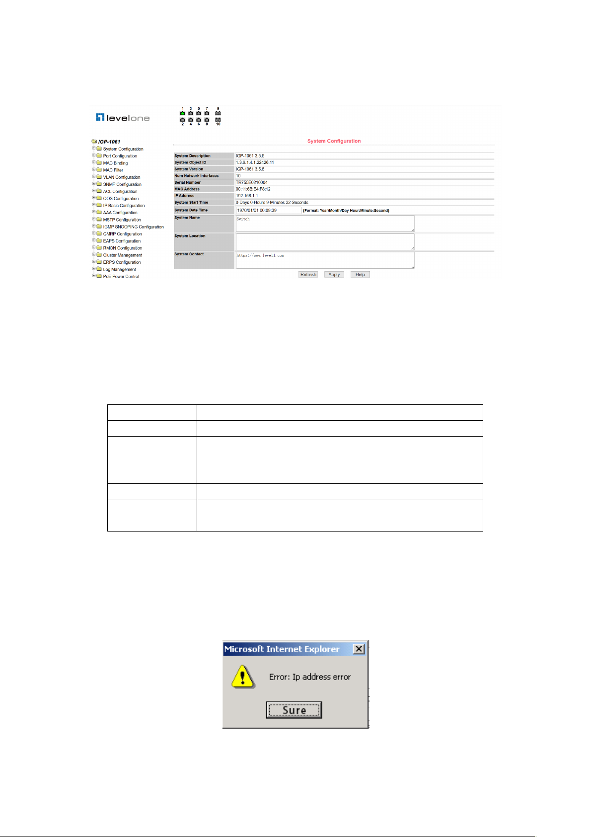
2.3.1 Basic information page
Figure 9 is the basic information configuration page through which users can configure the
basic information of the switch.
The system description shows the description of the relevant parameters of the system.
The system description symbol shows the identity of the system in network management.
The system version number shows the version number of the software currently in use by the
switch.
The number of network interfaces displays the current number of network interfaces in the
switch.
The system boot time shows the time the switch has started up to the present time.
The system clock shows the current clock of the system, and the user can modify the current
clock of the system, and the year, month, day, hour, minute, and second parameters are
required.
The system name displays the system name of the switch in the network, and the user can
modify the system name.
The system location displays the physical location of the switch in the network and the user
can modify the system location.
The system contact displays the contact and contact information of the current node, and the
user can modify the system contact.
Figure 9. Basic Information Page
9
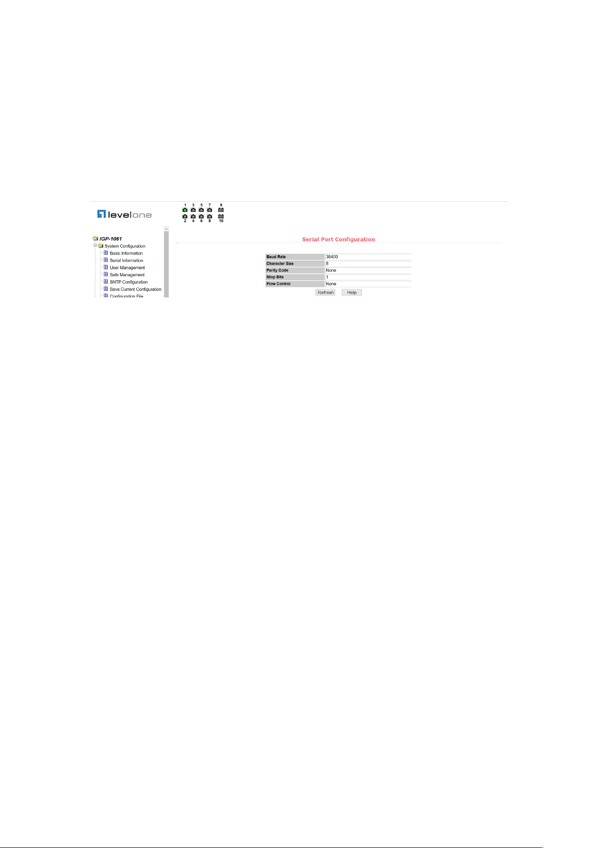
2.3.2 Serial port information page
Figure 10 is the serial port configuration page, which shows the serial port baud rate and other
serial port related information. When the host manages the switch through the serial port
terminal (such as the super terminal of Windows), the COM port configuration on the serial port
terminal must be consistent with the information on this page.
Figure 10. Serial port information page
2.3.3 User management page
Figure 11 is a user management page through which users can modify the anonymous user
(admin) password for the switch, and both Telnet and Web use the same anonymous user
password when multiple users are not enabled. The password is case-sensitive and can be set
to up to 16 characters. If you want to modify the password, the user needs to enter two new
passwords, and once the user clicks the application key, the new password is activated, and if
the switch does not enable the multi-user, the login dialog box is displayed (as shown in Figure
7), and the user is required to log in to the page again. The user must enter a new anonymous
user password to log in to the WEB page.
At the same time, users can configure multiple users through this page. The switch defaults to
no multi-user, that is, the multi-user management function is not enabled by default, and the
user name and password verification of the multi-user are not required at this time. For Telnet,
the multi-user management function is enabled when a user name is added, and the multi-user
management function is turned off when all users are deleted. For Web, when a user name is
added, the multi-user management function is enabled if it is a privileged user, and the
multi-user management function is turned off when all of the privileged users are deleted.
Anonymous when multi-user management is enabled User passwords will not take effect,
login to Telnet and Web requires multi-user user name and password authentication. When
the multi-user management function is turned off, if the anonymous user password is
configured, login to Telnet and Web requires anonymous user password authentication.

10
Figure 11. User management page
2.3.4 Security management page
Figure 12 is a security management configuration page through which the administrator can
control the network management service TELNET, WEB, and SNMP, can open (enable) or
disable the services, and can connect these services with the ACL group of the IP standard to
implement the source IP address control, Control the host's access to these services.
By default, the TELNET, WEB, and SNMP services are open and no ACL filtering, that is, all
hosts can access the three services of the switch. If an administrator does not want to provide
one or more of these services to other users for security, one or more of these services may be
shut down. If an administrator only wants a particular host to access one or more of these
services, one or more of these services can be ACL filtered. When a service is to be filtered by
an ACL, this service needs to be opened and an IP standard ACL group (1- 99) The ACL
group must exist at this time.
It is to be noted that if the administrator controls the WEB service on this page (such as closing
the WEB service), the user can not use the WEB page again, at this time, the switch can be
logged in by other means and the WEB service can be controlled to enable the user to use the
WEB page (such as opening the WEB service).
Figure 12. Security management page
2.3.5 SNTP configuration page
Figure 13 is the SNTP configuration page, through which the administrator can configure and
view the system clock.

11
Figure 13. SNTP configuration page
2.3.6 Current configuration page
Figure 14 is the current configuration page. This page allows users to view the current
configuration of the switch. The memory key stores the current configuration of the system in a
configuration file. Because the storage operation needs to erase the FLASH chip, this will take
a certain amount of time. When the user has configured the page and wants these
configurations not to be lost after restarting the switch, the memory key must be clicked in the
current configuration page in front of the exit page.
Figure 14. Current configuration page
2.3.7 Profile page
Figure 15 is the profile page. This page allows users to view the initial configuration of the
system. The initial configuration is actually a configuration file in FLASH, and when there is no
configuration file in FLASH, the system starts with the default configuration. The delete key is
used to delete the configuration file in FLASH. Click the delete key, a dialog box will pop up,
the dialog box prompts the user if you want to delete the configuration file, if so, press the

12
confirm key on the dialog box, otherwise press cancel key. The download key is used to
download the configuration file to the PC. Click on the download button, and a dialog box will
pop up, and the user will select the directory path and Save the configuration file. The file
name of the downloaded profile is a switch.cfg.
Figure 15. Profile page
2.3.8 File upload page
Figure 16 is a file upload page through which users can upload configuration files and image
files to the switch. Click the browse key to select the directory path of the uploaded
configuration file or image file on PC. Click the upload key to upload the configuration file or
image file, the suffix to the configuration file must be * .CFG, the image file must be supplied by
the manufacturer and the file name suffix must be *. Img. Do not click on another page or
restart the switch until the transfer results page returns; otherwise, the file transfer failure will
cause the system to crash.
Figure 16. File Upload Page
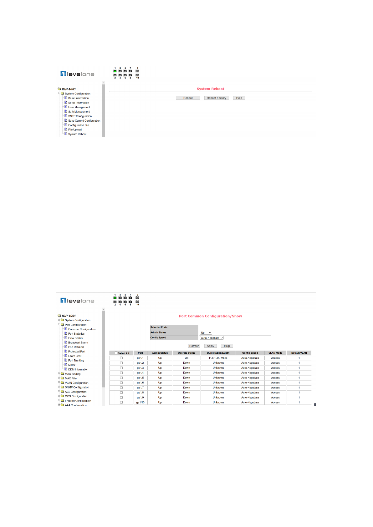
2.3.9 System reset page
Figure 17 is the system reset page through which the user restarts the switch. When the
restart key is clicked, a dialog box appears to prompt the user if he is sure to restart the switch.
If so, press OK, otherwise press cancel. You will no longer be able to open the Web page
when you restart.
13
Figure 17. System reset page
2.4 Port Configuration
2.4.1 Port configuration / port display page
Figure 18 is the port configuration / port display page. Users can enable or disable ports
through this page, set port speed, or view the basic information for all ports.
To set up a particular port, the user needs to select the appropriate port name from the
drop-down menu of the port. The port status defaults to up, which disables the port by
selecting down from the drop-down menu. Users can also choose to set the speed drop-down
menu to set the speed of the port, such as forced half-duplex 10m (half-10) on the port. Users
can view other basic information about all ports through this page.
Figure 18. Port configuration and port display page
2.4.2 Port statistics page
Figure 19 is a port statistics page. To view a specific port, the user needs the appropriate port
name from the drop-down menu of the port. The user can view the statistics of the port receive

14
and receive package through this page.
Figure 19. Port statistics page
2.4.3 Flow control page
Figure 20 is the flow control page. Users can open and close flow control for each port through
this page.
Turn on or off a port flow control by the pull on or off of the flow control. At the same time, you
can view the flow control status of all ports through this page.
Figure 20. Flow control page
2.4.4 Broadcast storm control page
Figure 21 is the broadcast storm control page. This page is used to configure broadcast
packets, multicast packets, and DLF packet suppression on ports.
Select the port you want to configure from the drop-down bar of the port. On and off are used
to turn on and off port broadcast suppression, multicast suppression and DLF suppression.
The suppression rate item is used to configure the suppression rate of the port in the range of
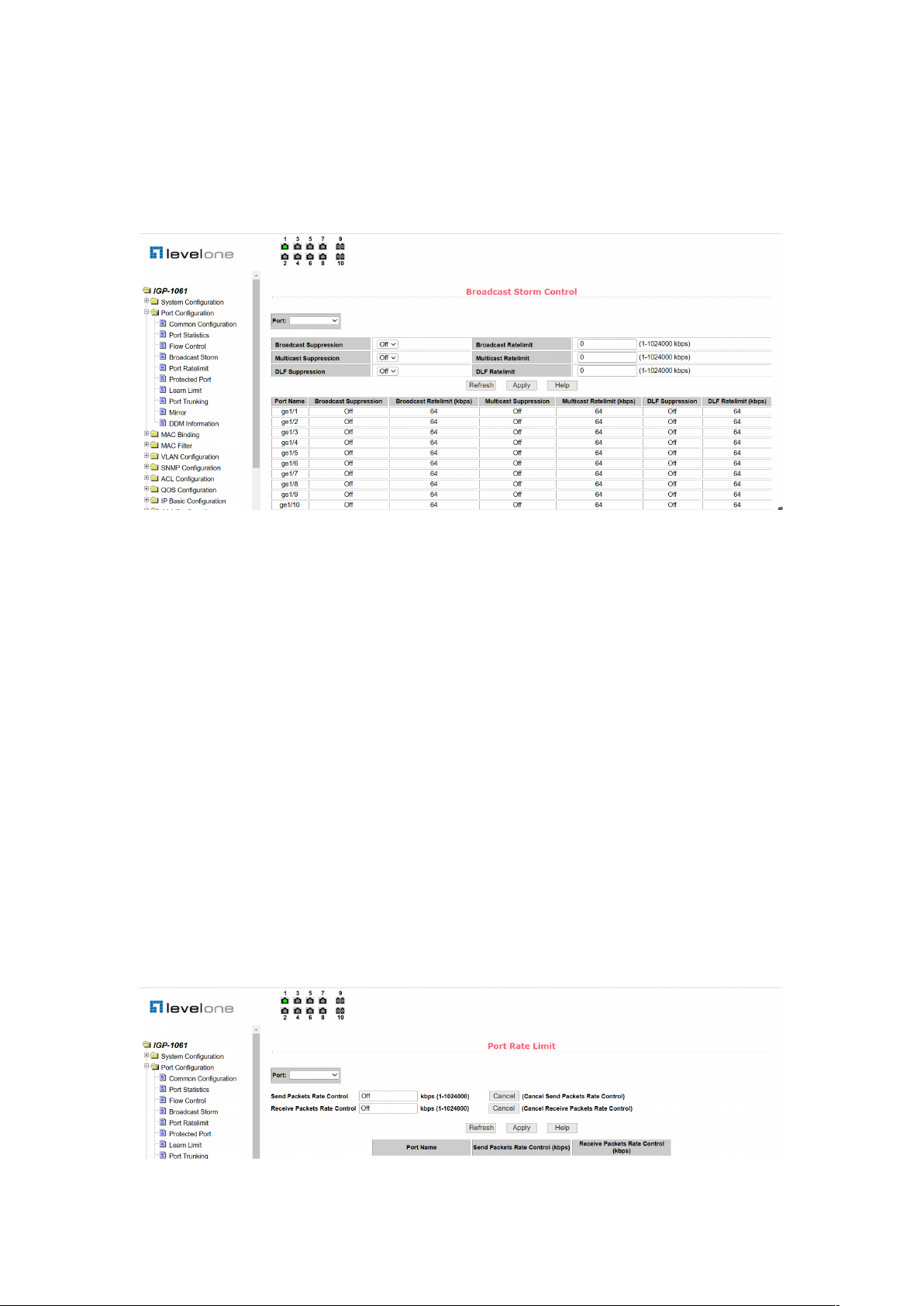
15
1!1024000 in kbits. The suppression rates of broadcast suppression, multicast suppression
and DLF suppression on the same port are the same. At the same time, through this page, you
can view the broadcast storm control configuration of all ports.
Figure 21. Broadcast storm control page
2.4.5 Port speed limit page
Figure 22 is the port speed limit page. This page is used to configure the rate at which ports
are sent and received.
Select the port you want to configure from the drop-down bar of the port. Sending packet
bandwidth control is used to configure and display the bandwidth control of sending packets,
the range is 1!1024000, and the unit is kbits, input and press the application key to take effect.
If the port is not configured with bandwidth control, it appears as off. The corresponding cancel
key is used to cancel the bandwidth control of the sending packet. The received packet
bandwidth control is used to configure and display the bandwidth control of the received
packet, the range is 1!1024000, and the unit is kbits, input and press the application key to
take effect. If the port is not configured with bandwidth control, it appears as off.
Correspondence The cancel key is used to cancel the bandwidth control of the received
packet.
If the bandwidth control is configured, it is displayed in the list.
Figure 22. Port speed limit page

16
2.4.6 Protection port page
Figure 23 is a protection port page. This page is used to configure the protection port.
Figure 23. Protection port page
2.4.7 Port learning limit page
Figure 24 is a port learning restriction page. The page is used to limit the number of MAC
addresses that the port can learn, in the range of 0-8191. The default value is 8191 and the
maximum value, indicating that the port does not have a learning limit. The study limit for all
ports is shown in the list.
Figure 24. Port learning limit page
2.4.8 Port aggregation configuration page
Figure 25 is a port aggregation configuration page. This page allows the user to configure port
aggregation. This page consists of four parts: Trunk Group ID selection, setting aggregation
method, configurable port, and group member port.
To create or modify a port aggregation, the user needs to select a trunk group ID from 1 to 8.
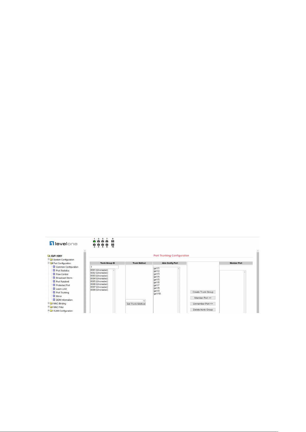
17
The user clicks the corresponding Trunk Group ID in the list box, and the information for the
trunk group is displayed in the group member port. To create a trunk group, select the
appropriate ID in the Trunk Group ID, click the key "Create a Trunk Group", and if the creation
is successful, the bracket dimension is created in the ID display column. If a trunk group is not
created, a bracket dimension is not created in the ID display column. to set up the port
aggregation method, select in the drop-down box above the list One of the aggregation
methods, click the key "Set up the aggregation method". To increase the port for aggregation,
select the aggregated port in the configurable port, and click the "Member Port =>" key. To
remove a port from an existing converged port, select the aggregated port in the group
member port and click the "Non-member port <=" key. To delete the entire trunk group, click
the "Delete Trunk Group" key.
The aggregation method configured during the page configuration is that the aggregation
method can only be configured for the existing trunk group corresponding to the selected trunk
group ID; only the member port can be added or deleted on the already existing trunk; in the
absence of a member port, a trunk group can be deleted.
The switch provides six port aggregation modes: based on source MAC address, destination
MAC address, source and destination MAC address, source IP address, destination IP
address, source and destination IP address based on destination IP address.
The switch supports up to 8 groups of port aggregation, each group of port aggregation
supports up to 8 ports, and each Trunk group can configure its own port aggregation method.
Figure 25. Port aggregation configuration page
2.4.9 Port mirror configuration page
Figure 26 is the port mirror configuration page, which allows the user to configure port mirror.
Port mirroring is listening for packets output by mirrored output ports and packets input by
mirrored input ports through mirrored ports. Only one mirrored port can be selected, while
multiple mirrored output ports and mirrored input ports can be selected. The page consists of
four parts: listening port, configurable port, listening direction and mirror configuration
information. When configuring a mirror port, configure the mirror port from the listening port,

18
the mirror port can only have one, then select the mirrored port from the configured port, select
the listening direction from the listening direction, the most Press the application key to take
effect, and the results are displayed in the mirror configuration information.
When the RECEIVE in the listening direction is selected, it means listening for the received
packets, TRANSMIT means listening for all packets sent and received, BOTH means listening
for all packets sent and received, NOT_RECEIVE means canceling listening for received
packets, NOT_TRANSMIT means canceling listening for packets sent, and NEITHER means
canceling listening for received and sending packets, that is, canceling the monitored port.
Figure 26. Port mirror configuration page
2.5 MAC Binding
2.5.1 MAC binding configuration page
Figure 27 is the MAC binding configuration page. This page is used to bind the port to the MAC
address.
The MAC entry on the page is used to enter the bound MAC address, VLAN ID entry to enter
the VLAN. to which the MAC address belongs.
Figure 27. MAC binding configuration page

19
2.5.2 MAC binding automatic conversion page
Figure 28 is the MAC binding automatic conversion page. This page is used to enable ports to
automatically bind MAC addresses.
Displays the existing dynamic MAC address of the port in the layer 2 hardware forwarding
table and the VLAN. to which it belongs You can select the entries and convert them to static
bindings.
Figure 28. MAC binding auto conversion page
2.6 MAC Filtering
2.6.1 MAC filter configuration page
Figure 29 is the MAC filtering configuration page. This page is used to configure port filtering of
MAC addresses.
The MAC entry on the page is used to enter the filtered MAC address, VLAN ID entry to enter
the VLAN. to which the MAC address belongs.
Figure 29. MAC filter configuration page
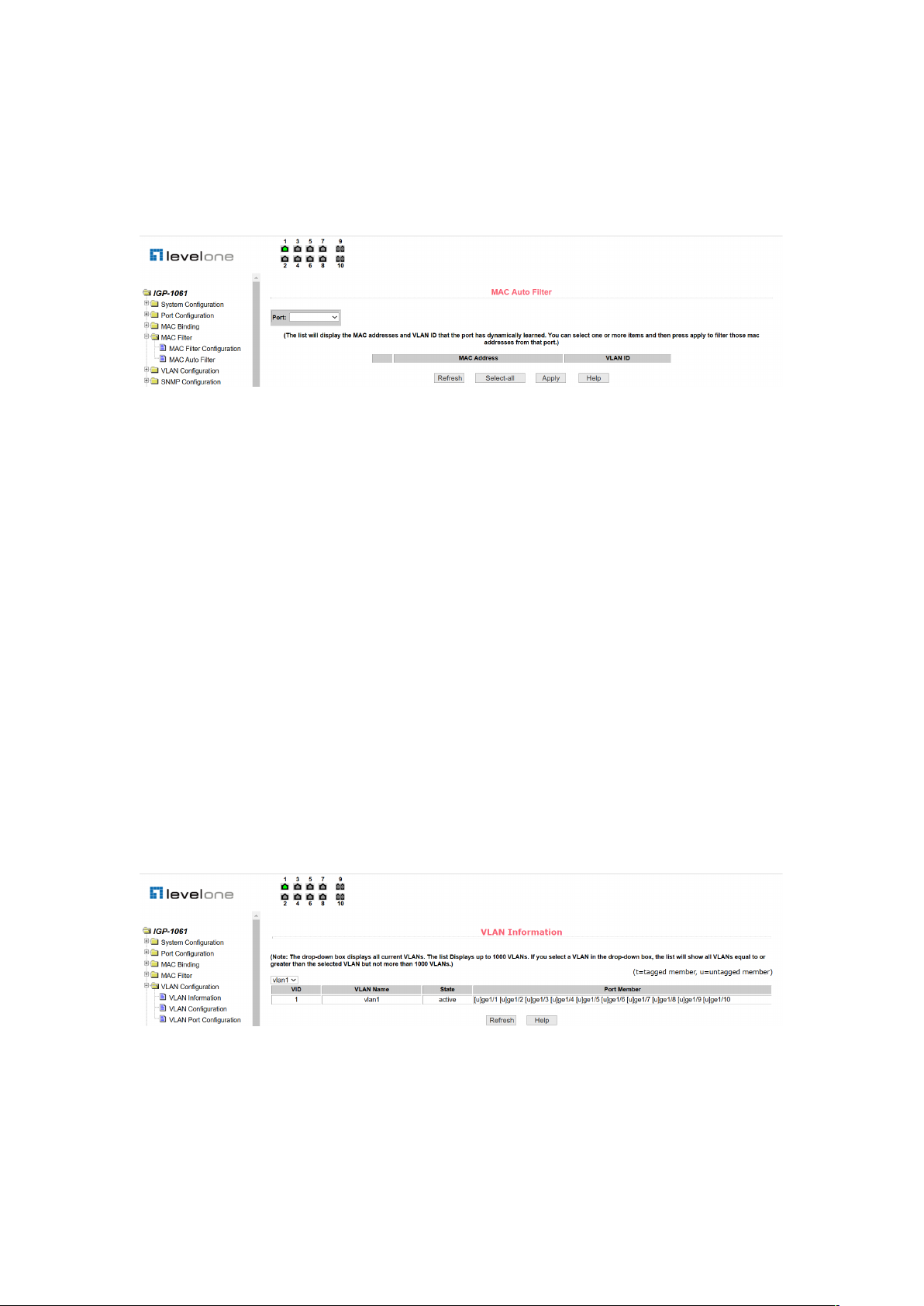
2.6.2 MAC filtering automatic conversion page
Figure 30 is the MAC filter automatic conversion page. This page is used to enable ports to
automatically bind MAC addresses.
20
Displays the existing dynamic MAC address of the port in the layer 2 hardware forwarding
table and the VLAN. to which it belongs You can select the entries and convert them to static
filtering configurations.
Figure 30. MAC filtering automatic conversion page
2.7 VLAN Configuration
2.7.1 VLAN information page
Figure 31 shows the current VLAN information page. The page is a read-only page that shows
the status of the current VLAN,VLAN and port members of the VLAN. The drop-down box
displays the VID, status and port members of up to 30 vlan in all current vlan, lists. Selecting a
vlan, list from the drop-down box displays information about up to 30 vlan whose VID is greater
than the vlan. However, if all vlan is not more than 30, no matter which vlan, list is selected
from the drop-down box, all vlan information is displayed.
A port can not be a member of VLAN, can be a tagged member of VLAN or a member of
untagged. The character meaning before the port of the page is as follows:
T tagged the port is a tagged member of this VLAN
U untagged this port is a untagged member of this VLAN
Figure 31 VLAN information page
2.7.2 Static VLAN configuration page
Figure 32 is a static VLAN configuration page that allows users to create VLAN.

21
If you want to create a new VLAN, user entering a VID, range from 2 to 4094.VLAN on the
active line, the system generates it according to VLAN ID and cannot be modified. Click the
application key, and the list box displays the VID and VLAN names of the user-created VLAN.
The switch creates VLAN1, by default and VLAN1 cannot be deleted.
If you want to delete an VLAN, user, you need to click on the corresponding VLAN in the list
box. The VLAN will be displayed in the active row, and click the delete (Delete) key to delete
the VLAN, and the information for the VLAN will be removed from the list box.
Figure 32. Static VLAN configuration page
2.7.3 VLAN port configuration page
Figure 33 is the VLAN port configuration page, which is used to configure VLAN on the port
and display the results of the configuration. The page is mainly composed of eight parts: Port,
mode, all current VLAN, ports belong to the VLAN, button "default VLAN = >", "tagged = >",
"untagged = >" and "non-member < =".
The port is the port that specifies the VLAN to be configured.
The mode Access specifies the port's VLAN mode as the ACCESS mode, in which the port is
the untagged member of the VLAN1, the default VLAN for the port is 1. The VLAN mode of the
hybrid specified port is HYBRID mode, and the port is the untagged member of the VLAN1 in
this VLAN mode. the default VLAN for the port is 1. The VLAN mode for the trunk port is
TRUNK mode, and in this VLAN mode the port is the tagged member of VLAN1, The default
VLAN for the port is 1.
All of the current VLANs refer to the currently-created VLAN, which can be configured as a
VLAN, and the user can select a VLAN from the list and select multiple VLANs.
The VLAN to which the port belongs shows the result of the VLAN port configuration. [p]
indicates that the VLAN is the default VLAN, [t] of the port indicates that the port is a tagged
member of the VLAN, and [u] indicates that the port is an unmarked member of the VLAN.
When VLAN is deleted, the user selects VLAN, from the list to select more options.
Press the key "default VLAN =>" to configure the default VLAN, for the port to select a VLAN.
from all the current VLAN.

22
The key "tagged = >" configuration port is a tagged member of the specified VLAN, selecting
one or more VLAN. from all current VLAN.
The key "untagged =>" configuration port is a untagged member of the specified VLAN,
selecting one or more VLAN. from all current VLAN.
Press the key "non-member <=" to remove the port from one or more VLAN specified, no
longer a member of these VLAN, and select one or more VLAN. from the VLAN to which the
port belongs.
Figure 33. VLAN port configuration page
8. SNMP configuration
(1) SNMP community configuration page
Figure 34 is an SNMP community configuration page that allows the user to configure the
name and read and write permissions of the switch's community. A total of eight entries can be
configured.
By default, a switch has a union of public names, which is read-only. Correspondingly, there is
only one active entry on the page, the union name is public, and the permissions are read-only.
When the switch needs to perform network management through SNMP, you need to
configure a shared body with readable and writable permissions.
Figure 34. SNMP community configuration page
23
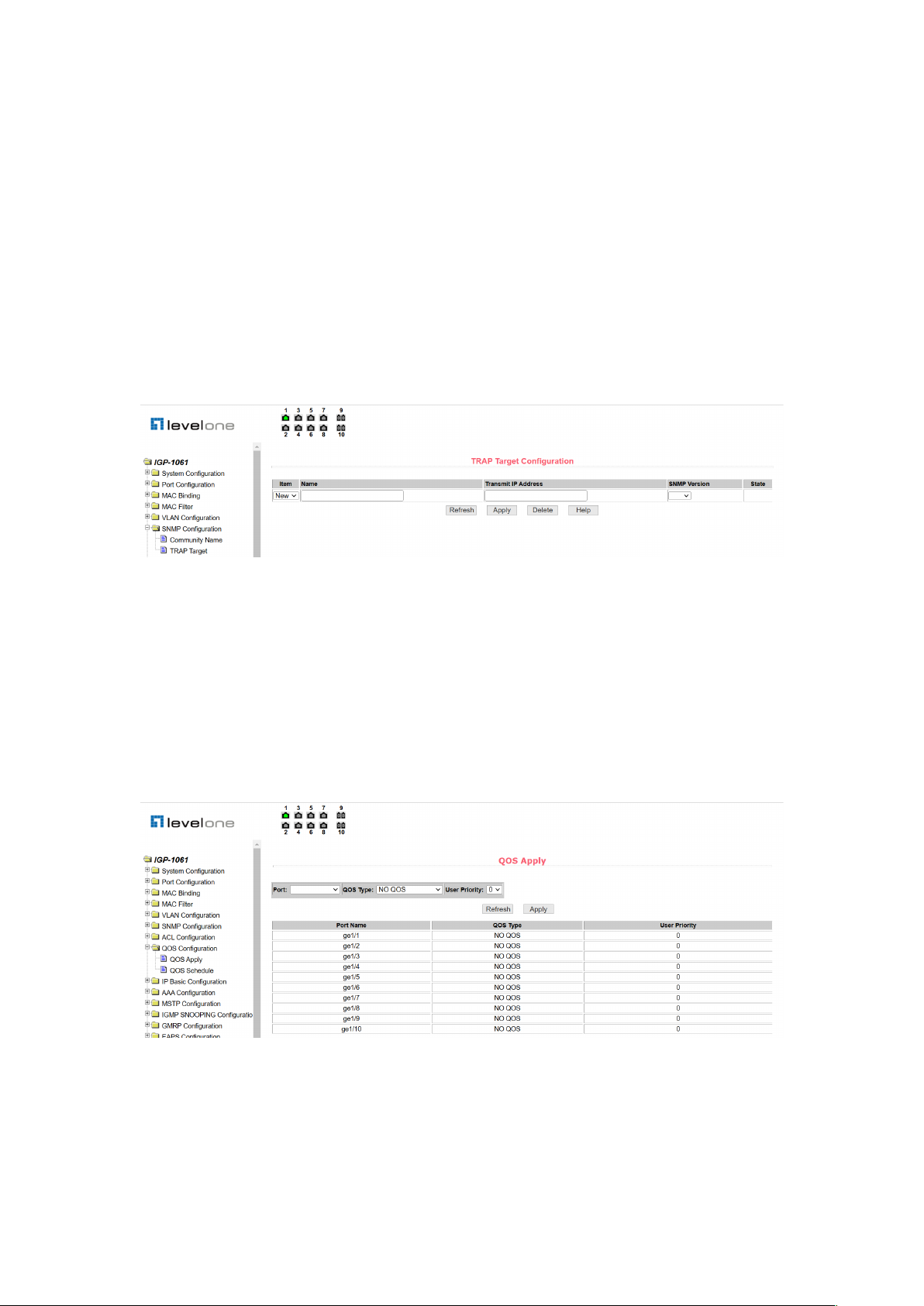
(2) TRAP target configuration page
Figure 35 is a TRAP target configuration page that allows the user to configure the IP address
of the workstation receiving the TRAP message and some parameters of the TRAP protocol
packet.
When configuring an entry, the name is used to enter the TRAP name, the transfer IP address
is used to enter the destination address, and the SNMP version is used to select the version of
the TRAP package. If the setting is successful, the status in the entry will show as active. If the
configuration is successful, the SNMP TRAP function will work. If a link up or link down occurs,
the switch will automatically send a TRAP packet to the destination address.
Figure 35. TRAP target configuration page
9. Qos configuration
(1) Qos application page
Figure 36 is the Qos application page, through which users can configure the Qos type of port
and modify the default user priority. The list is the Qos type of the real-time display port and the
user's default priority.
Figure 36. Qos application page
(2) Qos scheduling page
Figure 37 is the Qos scheduling page, through which users can configure the Qos scheduling

24
type of ports and modify the priority of queues. The list is the real-time display port scheduling
and the weight of each queue.
Figure 37. Qos scheduling page
10. ACL configuration
(1) ACL standard IP configuration page
Figure 38 shows the ACL standard IP configuration page, through which the user can establish
a rule library for the ACL standard IP. The user can select an ACL group number (ranging from
1-99, or 1300-1999) to create one or more rules in that group. The only field that can be
matched in a rule is the source IP address (with mask).
Figure 38. ACL standard IP configuration page
When you configure a rule, the source IP address needs to be masked and the rule can match
the set of IP addresses. The address mask is represented by an inverse code. If the rule
matches the IP address range 192.168.1.0 to 192.168.1.255, the IP address can be
192.168.1.1 and its mask is 0.0.0.255.
When users configures a rule, each rule must have a filtering mode: Allow or Deny.
When users create a rule in a rule group, the system automatically assigns a rule number to

25
the rule. When you delete a rule in a rule group, the other rules are unchanged. The system
automatically assigns a rule to a rule group. Sort. If the user wants to delete the entire rule
group, you can select all and then click the "Delete" button.
(2) ACL extended IP configuration page
Figure 39 shows the ACL extended IP configuration page. The user can establish a rule base
for ACL extended IP. And users can select an ACL group number (ranging between 100-199
or 2000-2699) to create one or more rules in the group. Fields that can be matched in a rule:
active IP address (with mask), destination IP address (with mask), protocol type (such as
ICMP, TCP, UDP, etc.), source port and destination port (for TCP and UDP only) Protocol is
valid), TCP control flag.
Figure 39. ACL extended IP configuration page
When users configure the rules, both the source and destination IP addresses need to be
masked, and the rules can match sets of IP addresses. The address mask is an inverse
representation, and if the rule matches the IP address range 192.168.1.0 to 192.168.1.255, the
IP address can be 192.168.1.1 and the mask is 0.0.0.255.
When users configures a rule, each rule must have a filtering mode: Allow or Deny.
When users create a rule in a rule group, the system will automatically give the rule a rule
number, when deleting a rule in a rule group, other rules remain unchanged, the system will
automatically sort the rules in a rule group. If the user wants to delete the entire rule group, he
can select all of them and then press the"Delete" button.
(3) ACL MAC IP configuration page

26
Figure 40 shows the ACL MAC IP configuration page. Users can establish a rule base for ACL
MAC IP through this page. The user can select an ACL group number (ranging between 700
and 799) and create one or more rules in the group. Field active MAC address (with address
match bit), source IP address (with address match bit), destination IP address (with address
match bit), and VLAN ID that can be matched in one rule.
Figure 40. ACL MAC IP configuration page
When configuring a rule, the source MAC address, source IP address, and destination IP
address must have address matching bits. The rule can match the set of MAC addresses and
IP addresses. For example, if the rule matches the IP address range 192.168.1.0 to 192.168.1.
255, the IP address can be 192.168.1.1 and its mask is 0.0.0.255.
When a user configures a rule, each rule must have a filtering mode: Allow or Deny.
When you create a rule in a rule group, the system automatically assigns a rule number to the
rule. When you delete a rule in a rule group, the other rules are unchanged. The system
automatically assigns a rule to a rule group. Sort. If the user wants to delete the entire rule
group, you can select all and then press the "Delete" button.
When configuring a rule, the VLAN ID must be in the range of 0 to 4094, including 0 and 4094,
where 0 is all.
"4#
ACL MAC ARP configuration page
Figure 41 shows the ACL MAC ARP configuration page. You can use this page to create a rule
base for ACL MAC ARP. The user can select an ACL group number (ranging between
1100-1199) and create one or more rules in the group. The fields that can be matched in a rule
are ARP operation type, sending MAC address (with address matching bit), and sending IP
address (with address matching bit).

27
Figure 41. ACL MAC ARP configuration page
When configuring a rule, the user needs to match the MAC address and the IP address with
the address matching bit. The rule can match the set of MAC address and IP address. For
example, if the rule matches the IP address range 192.168.1.0 to 192.168.1. 255, the IP
address can be 192.168.1.1 and its mask is 0.0.0.255.
When a user configures a rule, each rule must have a filtering mode: Allow or Deny.
When users create a rule in a rule group, the system automatically assigns a rule number to
the rule. When you delete a rule in a rule group, the other rules are unchanged. The system
automatically assigns a rule to a rule group. Sort. If the user wants to delete the entire rule
group, you can select all and then press the "Delete" button.
(5) ACL resource library information page
Figure 42 is an ACL repository information page, which displays all the rules and reference
information configured in the current ACL.
Figure 42. ACL resource library information page
(6) ACL Reference Configuration Page
Figure 43 is an ACL reference configuration page that allows users to select an ACL group for
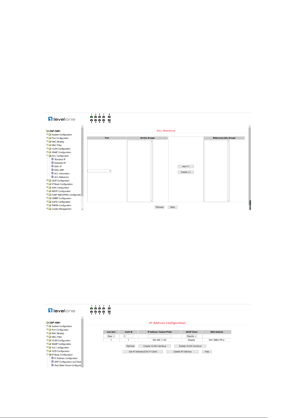
28
a port through the page, and write the rules in this ACL group to port hardware logic to cause
the port to perform an ACL filtering on the received packet in accordance with these rules.
When an ACL group is selected for an interface, you can select the IP standard, IP extension,
MAC IP, and MAC ARP ACL group. The selected ACL group must exist. Select from the ACL
rule group list and press the Add key. When deleting an ACL group, select an ACL group from
the list of referenced rule groups and press the "Delete" button.
Figure 43. ACL reference configuration page
11. IP basic configuration
(1) VLAN interface configuration page
Figure 44 is the VLAN interface configuration page, through which users can configure the
VLAN interface, delete the VLAN interface, configure the interface IP address, delete the
interface IP address and view the interface information. An existing VLAN can be set as an
interface, and the interface address can be configured on the set interface.
Figure 44. VLAN interface configuration page

29
By default, VLAN1 interface that cannot be deleted. Only one interface can be configured for a
VLAN.
(2) ARP configuration and display page
Figure 45 shows the ARP configuration and display page, which can display all the information
of the switch's ARP table. At the same time, users can configure static ARP entries, delete
ARP entries, and change dynamic ARP table entries into static ARP table entries.
When configuring a static ARP entry, the user needs to enter the IP address and MAC address,
which must be unicast MAC address, and then click the "add" button.
When deleting an ARP entry, the user can choose to delete an IP ARP entry, a network
segment ARP entry, all ARP entries, all dynamic ARP entries, and all static ARP entries. For
deleting the ARP table entry of an IP or deleting the ARP table entry of a network segment,
enter the specified IP address or IP network segment in the input box, and then click the
"delete" button.
When a dynamic ARP table is modified to a static ARP table, you can choose to modify the
dynamic ARP table in a network segment or all static ARP tables. For a network segment, you
need to enter the specified network segment in the input box, and then click the "Apply" button.
Figure 45. ARP configuration and display page
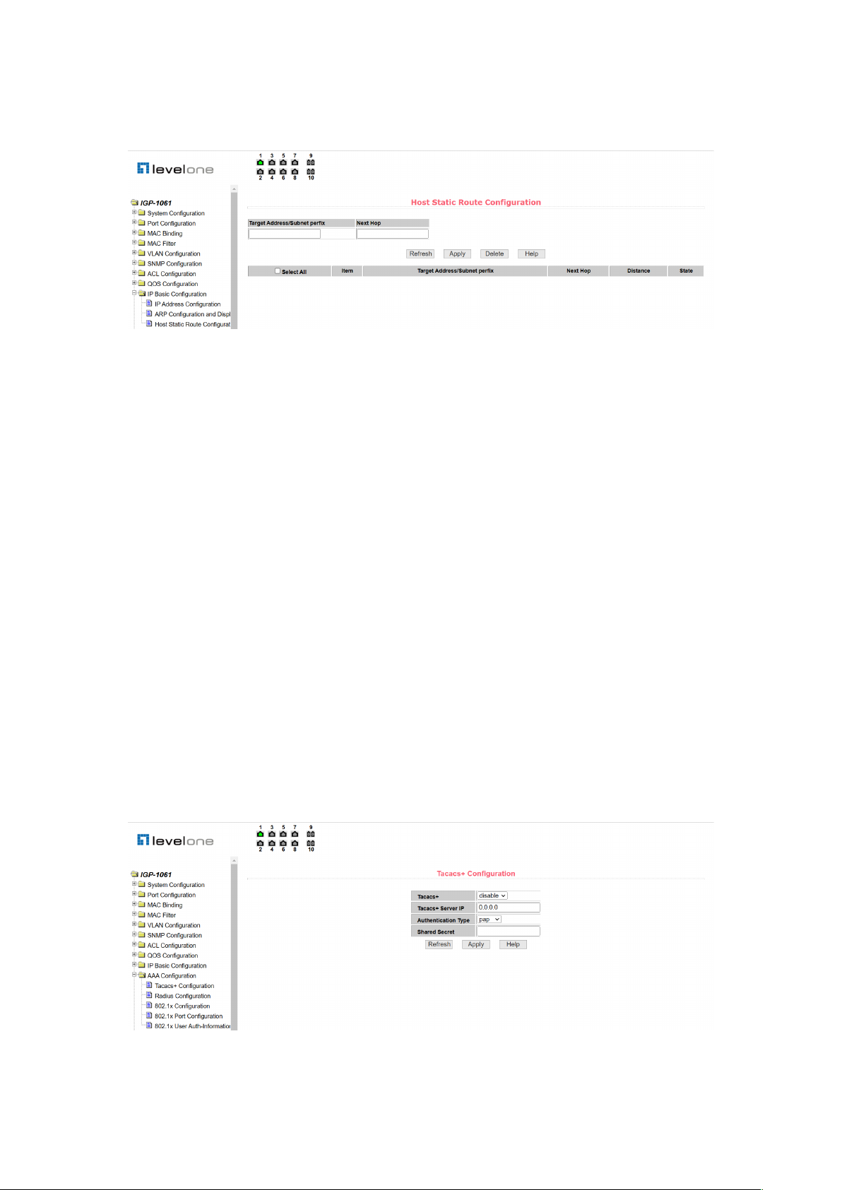
(3) Host static route configuration page
Figure 46 is the host static routing configuration page, through which users can add and delete
the host static routing of switches. By default, the switch does not configure host static routing.
Users can configure the default routing through this page, which means the destination
address/subnet prefix is 0.0.0.0/0.
30
Figure 46. Host static route configuration page
12. AAA configuration
(1) Tacacs+ configuration page
Figure 47 shows the Tacacs+ configuration page. Users can configure information related to
Tacacs+, including enabling Tacacs+ function, configuring the IP address of the Tacacs+
server, certification type, and sharing secret keys.
Before using the Tacacs+ function, you must enable the Tacacs+ function. The default
configuration is not enabled.
Configure the IP address of the Tacacs+ server. This field must be set when using the
Tacacs+ function.
The certification type is PAP and CHAP. The default configuration is PAP certification.
The shared key is used to set the encrypted shared password between the switch and the
Tacacs+ server. This field must be set when doing certification and authorization, and it must
be the same as the setting on the Tacacs+ server.
Figure 47. Tacacs+ configuration page
31
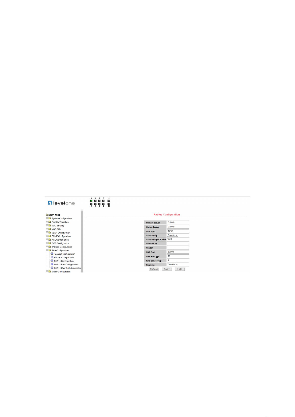
(2) Radius Configuration Page
Figure 48 is Radius configuration page. Users can configure Radius related information,
including:
l The IP address of the Radius server that must be set when doing certification billing.
l Optional Radius server IP address, this field can be set if there is an alternate Radius
server.
l The default value of the certification UDP port is 1812. Generally, the user does not
need to modify it.
l Billing is initiated by default, and billing is generally initiated when doing certification
and billing.
l The default value of the billing UDP port is 1813.
l The shared key is used to set the encrypted shared password between the switch and
the Radius server. This field must be set when doing certification and accounting, and
it must be the same as the setting on the Radius server.
l Vendor-specific information, users generally do not need to modify.
l NAS port, NAS port type, and NAS service type. These three are generally not
modified.
l Whether to enable or disable Radius roaming.
Figure 48. Radius configuration page
(3) 802.1x Configuration Page
Figure 49 is the 802.1x configuration page, through which the user can configure some
information related to 802.1x, including:
l Is the 802.1x protocol started? Be sure to start when doing certification billing.
l Whether the switch uses universal or extended certification.
l Is the recertification function turned on? The default is off, depending on the actual
situation when doing authentication billing. Turning on recertification will make the user
more reliable when using recertification billing, but will increase network traffic slightly.
l The recertification interval is valid only if recertification is enabled, and the default is 3600

32
seconds. This value should be set according to the actual situation when doing
authentication billing, but it should not be too small.
l Quiet Period, users generally do not need to modify this field.
l Quiet Period, users generally do not need to modify this field.
l Server timeout, users generally do not need to modify this field.
l Supplicant timeout, users generally do not need to modify this field.
l Number of "Max Request", users generally do not need to modify this field.
l Display the "Reauth Max" size.
l Client Version.
l Check Client, whether the client timing traffic packet is checked after certification is
passed.
Figure 49. 802.1x configuration page
(4) 802.1x port configuration page
Figure 50 shows the 802.1x port configuration page. You can use this page to configure the
802.1x port mode and the maximum number of supported hosts. You can also view the 802.1x
configuration of each port.
The 802.1x port mode includes four types: N/A state, Auto state, Force-authorized state, and
Force-unauthorized state.
When a port needs to perform 802.1x certification, set the port to the Auto state. If you do not
authenticate, you can access the network and set the port to the N/A state. The other two
states are rarely used in practical applications.

33
Figure 50. 802.1x port configuration page
When doing 802.1x certification, the maximum host number of port access by default is 256.
Users can modify this field, and the maximum number can be supported to 256.
(5) 802.1x user certification information page
Figure 51 is the 802.1x user certification information page, through which the user can view the
status information of all users accessed under a certain port.
Figure 51. 802.1x user certification information page
13.MSTP configuration
(1) MSTP global configuration page
Figure 52 shows the MSTP global configuration page, where users can configure global MSTP
parameters.

34
Figure 52. MSTP global configuration page
"2#
MSTP port configuration page
Figure 53 is the MSTP port configuration page through which the user can configure the port
MSTP parameters.
Figure 53. MSTP port configuration page
(3) MSTP port information page
Figure 54 is the MSTP port information page, through which the user can view the specific
status of the port MSTP.
Figure 54. MSTP port information page

35
14.IGMPSNOOPING Configuration
(1) IGMPsnooping global configuration page
Figure 55 shows the IGMPsnooping global configuration page, through which the user can
enable IGMPsnooping.
Figure 55. IGMPsnooping global configuration page
(2) Multicast group information page
Figure 56 is a multicast group information page. Users can view igmp snooping multicast
program information through this page.
Figure 56. Multicast group information page
15. GMRP configuration
(1) GMRP global configuration page
Figure 57 is the GMRP global configuration page, which allows users to enable GMRP.

36
Figure 57. GMRP global configuration page
(2) GMRP port configuration page
Figure 58 is the GMRP port configuration page, through which users can enable port GMRP
and view port information.
Figure 58. GMRP port configuration page
(3) GMRP state machine page
Figure 59 is a GMRP state machine page, through which the user can view the state machine
information established by the GMRP.
Figure 59. GMRP state machine page

37
16. EAPS Configuration
(1) EAPS configuration page
Figure 60 is the EAPS configuration page through which the user can configure EAPS.
Figure 60. EAPS configuration page
(2) EAPS information page
Figure 61 is an EAPS information page that allows users to view EAPS configuration
information.
Figure 61. EAPS information page
17. RMON Configuration
(1) RMON statistics group configuration page
Figure 62 is the RMON statistics group configuration page, through which users can configure
the RMON statistics group. Select a port from the drop-down list to view/configure the RMON

38
statistics group configuration for that port. When not configured, index number is 0, fill in the
correct index number (range 1 to 100), owner is optional, you can configure the RMON
statistics group for this port. The statistics table shows the port statistics from the successful
configuration.
Figure 62. RMON statistics group configuration page
(2) RMON history group configuration page
Figure 63 shows the RMON history group configuration page through which users can
configure the RMON history group. Select a port from the drop-down list to view/configure the
RMON history group configuration for that port. When not configured, index number is 0, fill in
the correct index number (range 1 to 100), interval, request Buckets, owner is optional, RMON
history group can be configured for this port. Interval refers to the time interval of data
collection, in seconds, with a range of 1-3600.
The requested Buckets are the allocated storage size, indicating how many records are stored
and the range is 1-100. The statistics table shows the historical data collected since the
successful configuration.
Figure 63. RMON history group configuration page

39
"3#
RMON alarm group configuration page
Figure 64 shows the RMON alarm group configuration page. You can create or modify a
RMON alarm group on this page. Select a configured alarm group from the drop-down list to
view/configure its information. Select New to create it.
The index number ranges from 1 to 60, and the interval ranges from 1 to 3600. In seconds, the
monitoring object must fill in the MIB node. The comparison mode can be either absolute or
delta. In addition, the upper and lower valves must be filled in. Value, event index, owner is
optional.
The alarm value is read-only and shows the sampled value when the alarm was last issued.
The event index refers to the index number of the RMON event group and must be configured
in advance.
Figure 64. RMON alarm group configuration page
"4#
RMON event group configuration page
Figure 65 shows the RMON event group configuration page, which allows users to create or
modify RMON event groups.
Select a configured event group from the drop-down list to view/configure its information, or
select New to create it.
The index number ranges from 1 to 60. The description is in the form of a string. You can
select either none (no operation), log (logging), snmp-trap (sending Trap alarm), or
log-and-trap (recording and sending traps). ), the share name does not work in this device, the
owner is optional. The last send time is read-only and shows the time the event was last sent.

40
Figure 65. RMON event group configuration page
18. The Cluster Configuration
"1#
NDP Configuration Page
Figure 66 is an NDP configuration page that allows users to configure NDP. The information
that can be set includes: selecting a port, enabling the port NDP function, enabling the global
NDP function, the interval for sending NDP packets, and the aging time of NDP packets on the
receiving device.
Port selection, port can be selected as needed, and enable port NDP function. For NDP to
work properly, both global and port NDP functions must be enabled.
Configure the aging time of NDP message sent by this device on the receiving device, the
effective time range is 1-4096 seconds, and the default configuration is 180 seconds.
Configure the time interval of NDP message sending, the effective time range is 1-4096
seconds, and the default configuration is 60 seconds.
Figure 66. NDP configuration page
41
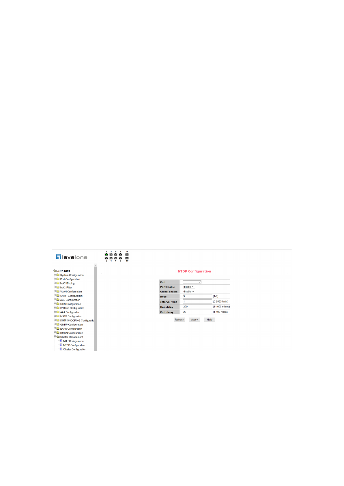
(2) NTDP Configuration Page
Figure 67 shows the NTDP configuration page through which users can configure NTDP.
The configurable information includes: select port, enable port NTDP function, enable global
NTDP function, scope of topology collection, time interval of timing topology collection, delay
time of forwarding packet on the first port, and delay time of forwarding packet on other ports.
Port selection: port can be selected as needed, and enable port NTDP function. NTDP must
enable both global and port NTDP functions to function properly.
Configure the scope of topology collection: the effective range is 1-6. By default, the farthest
device from the topology collection is 3 hops away.
Configure the interval for collecting periodic topology information. The valid range is 0-65535
minutes. The default configuration is 1 minute.
Configure the delay for forwarding packets on the first port. The valid range is 1-1000
milliseconds. The default configuration is 200 milliseconds.
Configure the delay for forwarding packets on the first port. The valid range is 1-100
milliseconds. The default configuration is 20 milliseconds.
Figure 67. NTDP configuration page
(3) Cluster Configuration Page
Figure 68 shows the cluster configuration page, which allows users to configure the cluster
and view the cluster member table. The information that can be set includes: enabling the
cluster function, configuring the management VLAN, the address pool of the cluster, the
interval for sending handshake packets, the effective retention time of the device, the name of
the cluster, the method of joining the cluster, and deleting the cluster.

42
The cluster function is working properly and the cluster function must be enabled first.
Configure the management VLAN. The valid range is 1-4094. The default configuration is
vlan1.
Configure the private IP address range of the member devices in the cluster. The valid range
of the IP address is 0.0.0.0~255.255.255.255. The valid range of the mask length is 0~32.
Configure the interval for sending handshake packets. The valid range is 1-255 seconds. The
default configuration is 10 seconds.
Configure the effective hold time of the device. The valid range is 1-255 seconds. The default
configuration is 60 seconds.
To establish a cluster, you need to configure the cluster name and the method of joining the
cluster. There are two methods: manual and automatic. After the cluster is established, it can
be automatically switched to manual, but manual cannot be switched to automatic. The cluster
name can be changed manually.
After a cluster is created, member devices and candidate devices can be viewed in the cluster
member table. You can delete member devices or add candidate devices to member devices
based on roles.
Figure 68. Cluster configuration page
19. Log management
(1) Log information
Figure 69 is a log information page that allows users to view logs. Select the priority from the

43
drop-down list, you can view the log of this level, click refresh to view the log of the latest
record.
Figure 69. Log information page
20. PoE management
(1) Poe port configuration
Figure 70 shows the POE port configuration page, which can turn on and off the POE function, set
the total power supply power, and restart the POE port separately; You can view the used power,
the percentage of used power, and the usage status of each Poe port.
Figure 70. POE port configuration
(2) Poe Policy Configuration
Figure 71 shows Poe policy configuration, which can set the policy behavior service of each Poe
port.

44
Figure 71. POE Policy Configuration
(3) PD Query Configuration
Figure 72 shows the PD query configuration, turn on and off the POE auto check function, view
the IP address of the PD device, and query the POE auto check function status information of each
Poe port.
Figure 72. PD Query Configuration
 Loading...