

Page 1
IES-1085
4 x 802.3af + 4 x 802.3at + 2 GE SFP Managed Switch -40 to 75C, DIN-rail
User Manual
v1.00 - 1206
Page 2

Preface
This manual describes how to install and use the Industrial Managed PoE (Power over
Ethernet) Ethernet Switch. This switch introduced here is designed to deliver full scalability
with SNMP/RMON web-based management functions by providing:
To get the most out of this manual, you should have an understanding of Ethernet
networking concepts.
In this manual, you will find:
Features on the Industrial Managed PoE Ethernet Switch
Illustrative LED functions
Installation instructions
Management Configuration
Specifications
User Manual Page 2
Page 3

Table of Contents
PREFACE .................................................................................................................................................. 2
TABLE OF CONTENTS .................................................................................................................................... 3
QUICK START GUIDE .............................................................................................................................. 5
PHYSICAL DESCRIPTION ............................................................................................................................................ 5
FUNCTIONAL DESCRIPTION ....................................................................................................................................... 7
CONSOLE CONFIGURATION ....................................................................................................................................... 8
WEB CONFIGURATION ............................................................................................................................................. 9
PRODUCT OVERVIEW ........................................................................................................................... 10
INDUSTRIAL MANAGED ETHERNET SWITCH ................................................................................................................ 10
PACKAGE CONTENTS .............................................................................................................................................. 10
PRODUCT HIGHLIGHTS ........................................................................................................................................... 11
FRONT PANEL DISPLAY ........................................................................................................................................... 13
PHYSICAL PORTS ................................................................................................................................................... 14
SWITCH MANAGEMENT ......................................................................................................................................... 15
INSTALLATION ....................................................................................................................................... 16
SELECTING A SITE FOR THE SWITCH ........................................................................................................................... 16
WIRING DIAGRAM ................................................................................................................................................ 16
DIN RAIL MOUNTING ............................................................................................................................................ 17
CONNECTING TO POWER ........................................................................................................................................ 17
CONNECTING TO YOUR NETWORK ............................................................................................................................ 19
SWITCH MANAGEMENT ....................................................................................................................... 20
MANAGEMENT ACCESS OVERVIEW ........................................................................................................................... 20
ADMINISTRATION CONSOLE (CLI) ............................................................................................................................ 21
WEB MANAGEMENT ............................................................................................................................................. 22
SNMP-BASED NETWORK MANAGEMENT ................................................................................................................. 22
PROTOCOLS ......................................................................................................................................................... 22
MANAGEMENT ARCHITECTURE ................................................................................................................................ 23
SNMP & RMON MANAGEMENT ........................................................................................................... 24
OVERVIEW ........................................................................................................................................................... 24
SNMP AGENT AND MIB-2 (RFC 1213) .................................................................................................................. 24
RMON MIB (RFC 2819) AND BRIDGE MIB (RFC 1493) ........................................................................................... 25
WEB-BASED BROWSER MANAGEMENT ........................................................................................... 27
LOGGING ON TO THE SWITCH ................................................................................................................................... 27
UNDERSTANDING THE BROWSER INTERFACE ............................................................................................................... 28
SYSTEM ............................................................................................................................................................... 30
PORT .................................................................................................................................................................. 40
SWITCHING .......................................................................................................................................................... 44
TRUNKING ........................................................................................................................................................... 48
STP / RING ......................................................................................................................................................... 49
VLAN ................................................................................................................................................................ 56
QOS ................................................................................................................................................................... 60
SNMP ............................................................................................................................................................... 62
802.1X .............................................................................................................................................................. 66
OTHER PROTOCOLS ............................................................................................................................................... 69
COMMAND LINE CONSOLE MANAGEMENT ..................................................................................... 73
User Manual Page 3
Page 4

ADMINISTRATION CONSOLE .................................................................................................................................... 73
SYSTEM ............................................................................................................................................................... 82
PORT .................................................................................................................................................................. 92
SWITCHING .......................................................................................................................................................... 99
TRUNKING ......................................................................................................................................................... 108
STP ................................................................................................................................................................. 109
VLAN .............................................................................................................................................................. 122
QOS ................................................................................................................................................................. 128
SNMP ............................................................................................................................................................. 131
802.1X ............................................................................................................................................................ 138
OTHER PROTOCOLS ............................................................................................................................................. 143
SPECIFICATIONS .................................................................................................................................. 154
APPENDIX A .......................................................................................................................................... 155
APPENDIX B .......................................................................................................................................... 156
User Manual Page 4
Page 5
Quick Start Guide
This quick start guide describes how to install and use the Industrial Managed PoE (Power
over Ethernet) Ethernet Switch. This is the switch of choice for harsh environments
constrained by space.
Physical Description
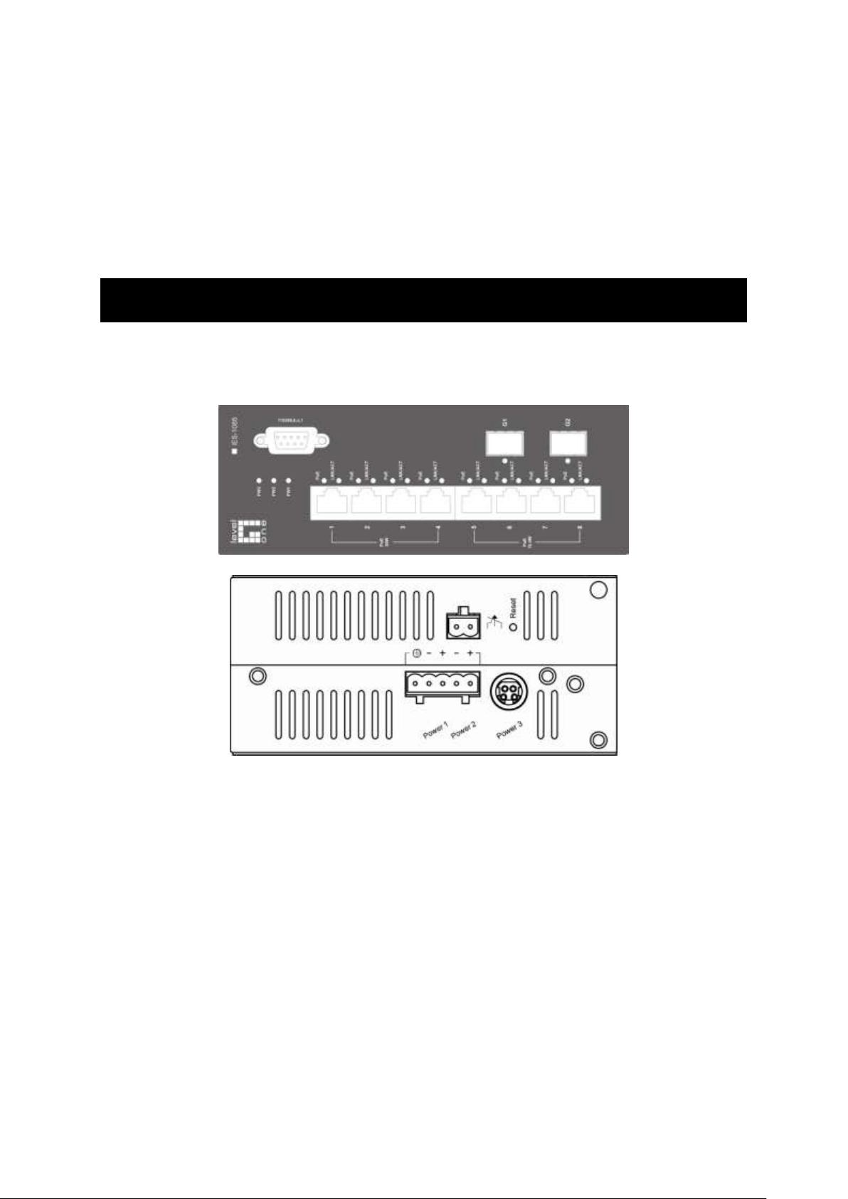
The Port Status LEDs and Power Inputs
User Manual Page 5
Page 6
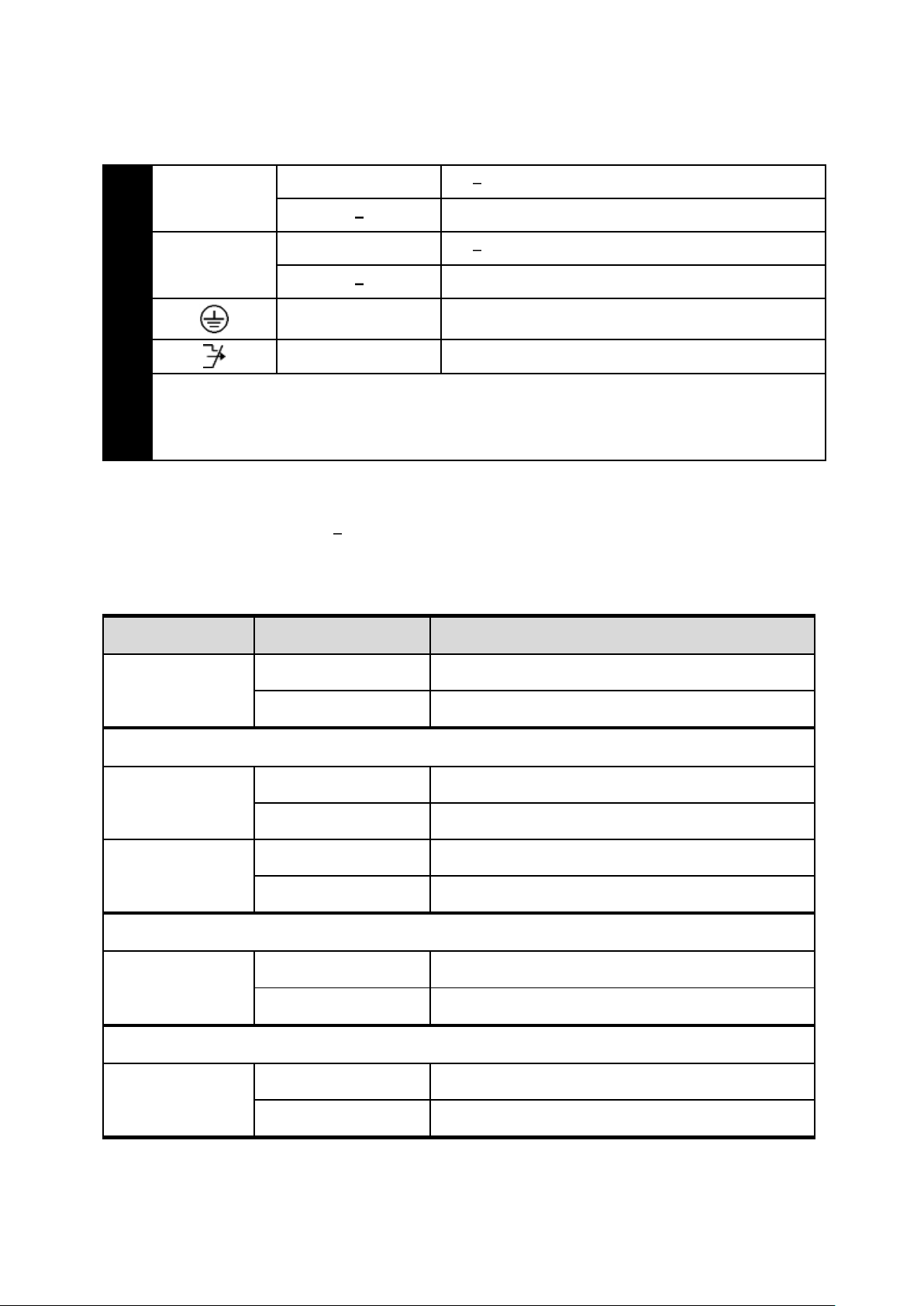
Power Input
Terminal Block
PW1
+
47 57VDC
Power Ground
PW2
+
47 57VDC
Power Ground
Earth Ground
Relay Output
1A @ 250VAC
Relay Alarm warning signal disable for following:
1. The relay contact closes if Power1 and Power2 are both failed but Power3 on
2. The relay contact closes if Power3 is failed but Power1 and Power2 are both on
LED
Status
Description
PW 1,2,3
Steady
Power On
Off
Power Off
10/100Base-TX
LNK/ACT
Steady
Network connection established
Flashing
Transmitting or Receiving data
PoE
Steady
Power Device (PD) is connected
Off
Power Device (PD) is disconnected
100Base-FX
LNK/ACT
Steady
Network connection established
Flashing
Transmitting or Receiving data
10/100/1000Base-TX & 1000Base-FX & SFP
LNK/ACT
Steady
Network connection established
Flashing
Transmitting or Receiving data
There are three power inputs can be used. Redundant power function is supported
PW3 is DC Jack type with 47 57VDC input
LED Status
User Manual Page 6
Page 7

Functional Description
Meets NEMA TS1/TS2 Environmental requirements such as temperature, shock, and
vibration for traffic control equipment.
Meets EN61000-6-2 & EN61000-6-4 EMC Generic Standard Immunity for industrial
environment.
RS-232 console, Telnet, SNMP v1 & v2c & v3, RMON, Web Browser, and TFTP
management.
Supports Command Line Interface in RS-232 console.
Supports 8192 MAC addresses. Provides 2M bits memory buffer.
Port 1 ~ Port 4 support IEEE802.3at Power over Ethernet (PoE) Power Sourcing
Equipment (PSE) and/or Port 5 ~ Port 8 support IEEE802.3af Power over Ethernet (PoE)
Power Sourcing Equipment (PSE).
Supports IEEE802.3/802.3u/802.3ab/802.3z/802.3x. Auto-negotiation,
1000Mbps-full-duplex, 10/100Mbps-full/half-duplex, Auto MDI/MDIX.
100Base-FX: Multi mode or Single mode duplex LC type. 100Base-BX: WDM Multi mode
or Single mode single LC type.
1000Base-SX/LX: Multi mode or Single mode duplex LC type. 1000Base-BX: WDM Multi
mode or Single mode single LC type.
Store-and-forward mechanism. Full wire-speed forwarding rate.
Alarms for power and port link failure by relay output.
Power Supply: Redundant 47-57VDC Terminal Block power inputs or 47-57VDC DC Jack
power input.
Field Wiring Terminal: Use Copper Conductors Only, 60/75℃, 12-24 AWG torque value 7
lb-in.
Operating voltage and Max. current consumption: 0.31A @ 48VDC. Power
consumption: Power consumption: 230W Max. (Full load with PoE), 15W Max. (Without
PoE).
-40℃ to 75℃ (-40℉ to 167℉) operating temperature range. Tested for functional
operation @ -40℃ to 85℃ (-40℉ to 185℉). UL508 Industrial Control Equipment
certified Maximum Surrounding Air Temperature @ 75℃ (167℉).
For use in Pollution Degree 2 Environment.
Industrial metal case.
Supports Din-Rail or Panel Mounting installation.
User Manual Page 7
Page 8
Console Configuration
Connect to the switch console:
Connect the DB9 straight cable to the RS-232 serial port of the device and the RS-232
serial port of the terminal or computer running the terminal emulation application.
Direct access to the administration console is achieved by directly connecting a
terminal or a PC equipped with a terminal-emulation program (such as HyperTerminal)
to the switch console port.
Configuration settings of the terminal-emulation program:
Baud rate: 115,200bps
Data bits: 8
Parity: none
Stop bit: 1
Flow control: none
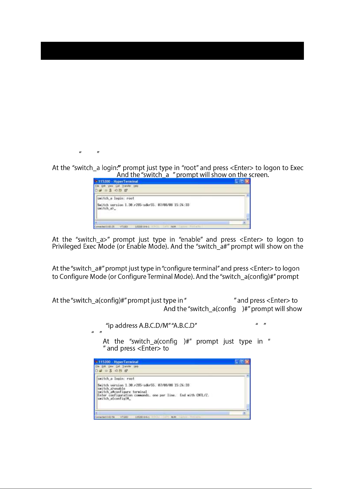
Press the Enter key. The Command Line Interface (CLI) screen should appear as below:
Logon to Exec Mode (View Mode):
Mode (or View Mode). >
Logon to Privileged Exec Mode (Enable Mode):
screen.
Logon to Configure Mode (Configure Terminal Mode):
will show on the screen.
Set new IP address and subnet mask for Switch:
interface vlan1.1
logon to vlan 1 (vlan1.1 means vlan 1). -if
on the screen.
Command Syntax: . specifies IP address. M specifies IP
subnet mask. M = 8: 255.0.0.0, 16:255.255.0.0, or 24: 255.255.255.0.
For example, -if ip address
192.168.1.10/24 set new IP address (192.168.1.10) and new IP
subnet mask (255.255.255.0) for Switch.
User Manual Page 8
Page 9
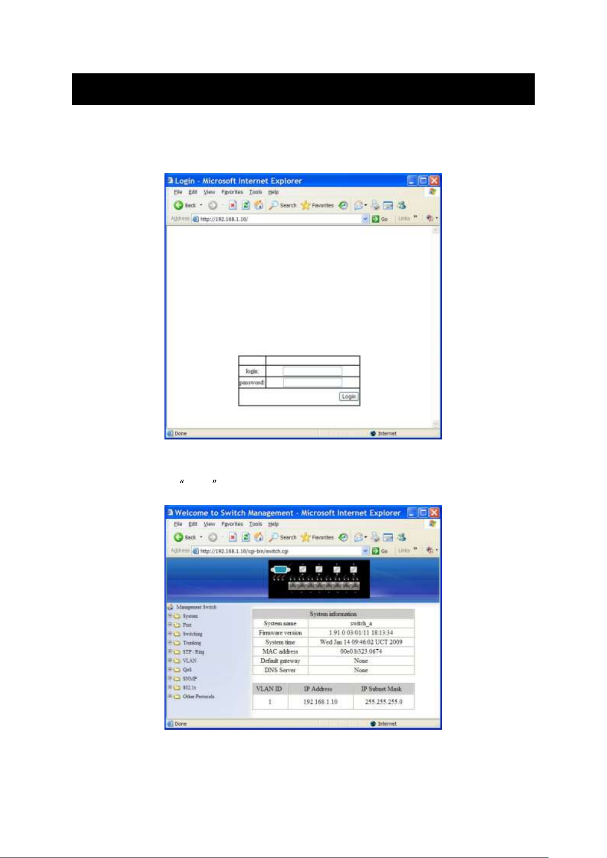
Web Configuration
Login the switch:
Specify the default IP address (192.168.1.10) of the switch in the web browser. A login
window will be shown as below:
Enter the factory default login ID: root.
Enter the factory default password (no password).
Then click on the Login button to log on to the switch.
User Manual Page 9
Page 10

Product Overview
Industrial Managed Ethernet Switch
Front View
Package Contents
When you unpack the product package, you shall find the items listed below. Please
inspect the contents, and report any apparent damage or missing items immediately to
your authorized reseller.
IES-1085
Quick Installation Guide
CD User Manual
RS-232 cable
User Manual Page 10
Page 11

Product Highlights
Basic Features
Meets NEMA TS1/TS2 Environmental requirements such as temperature, shock, and
vibration for traffic control equipment.
Meets EN61000-6-2 & EN61000-6-4 EMC Generic Standard Immunity for industrial
environment.
RS-232 console, Telnet, SNMP v1 & v2c & v3, RMON, Web Browser, and TFTP
management.
Supports Command Line Interface in RS-232 console.
Supports 8192 MAC addresses. Provides 2M bits memory buffer.
Port 1 ~ Port 4 support IEEE802.3at Power over Ethernet (PoE) Power Sourcing
Equipment (PSE) and/or Port 5 ~ Port 8 support IEEE802.3af Power over Ethernet (PoE)
Power Sourcing Equipment (PSE).
Supports IEEE802.3/802.3u/802.3ab/802.3z/802.3x. Auto-negotiation,
1000Mbps-full-duplex, 10/100Mbps-full/half-duplex, Auto MDI/MDIX.
100Base-FX: Multi mode or Single mode duplex LC type. 100Base-BX: WDM Multi mode
or Single mode single LC type.
1000Base-SX/LX: Multi mode or Single mode duplex LC type. 1000Base-BX: WDM Multi
mode or Single mode single LC type.
Store-and-forward mechanism. Full wire-speed forwarding rate.
Alarms for power and port link failure by relay output.
Power Supply: Redundant 47-57VDC Terminal Block power inputs or 47-57VDC DC Jack
power input.
Field Wiring Terminal: Use Copper Conductors Only, 60/75℃, 12-24 AWG torque value 7
lb-in.
Operating voltage and Max. current consumption: 0.31A @ 48VDC. Power
consumption: Power consumption: 230W Max. (Full load with PoE), 15W Max. (Without
PoE).
-40℃ to 75℃ (-40℉ to 167℉) operating temperature range. Tested for functional
operation @ -40℃ to 85℃ (-40℉ to 185℉). UL508 Industrial Control Equipment
certified Maximum Surrounding Air Temperature @ 75℃ (167℉).
For use in Pollution Degree 2 Environment.
Industrial metal case.
Supports Din-Rail or Panel Mounting installation.
Management Support
VLAN
Port-based VLAN
IEEE802.1Q tagged VLAN
User Manual Page 11
Page 12

TRUNKING
Port Trunking
PORT-SECURITY
Per-port programmable MAC address locking
Up to 24 Static Secure MAC addresses per port
PORT-MIRRORING
Port-mirroring
QOS (IEEE802.1p Quality of Service)
4 priority queues
INTERNETWORKING PROTOCOLS
Bridging:
IEEE802.1s Multiple Spanning Tree
IEEE802.1w Rapid Spanning Tree
IEEE802.1D Spanning Tree compatible
IEEE802.1Q GVRP
Ring
IP Multicast:
IGMP Snooping
Rate Control
NTP
NETWORK MANAGEMENT METHODS
Console port access via RS-232 cable (CLI, Command Line Interface)
Telnet remote access
SNMP agent:
MIB-2 (RFC1213)
Bridge MIB (RFC1493)
RMON MIB (RFC2819) statistics, history, alarm and events
VLAN MIB (IEEE802.1Q/RFC2674)
Private MIB
Web browser
TFTP software-upgrade capability
User Manual Page 12
Page 13
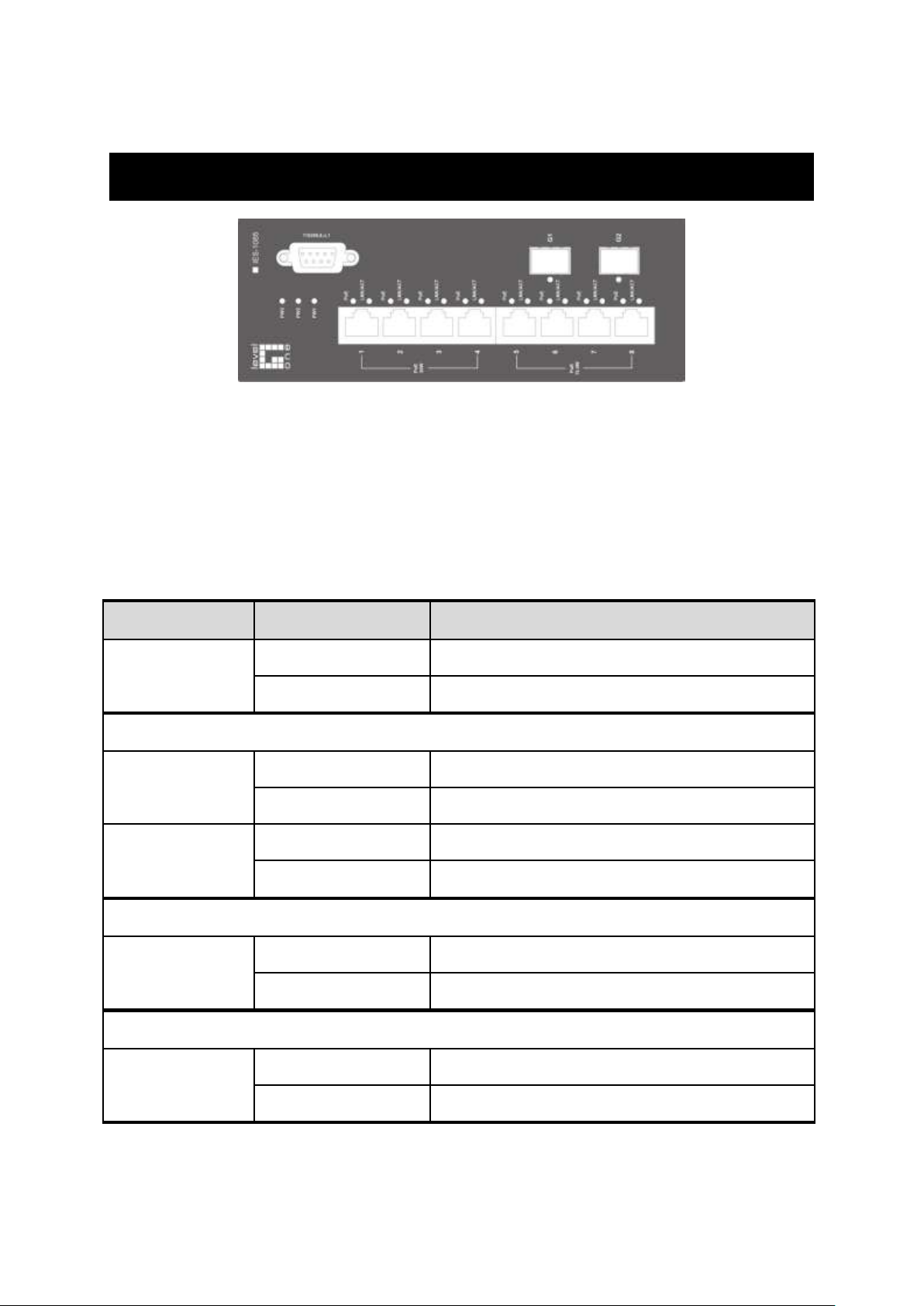
LED
Status
Description
PW 1,2,3
Steady
Power On
Off
Power Off
10/100Base-TX
LNK/ACT
Steady
Network connection established
Flashing
Transmitting or Receiving data
PoE
Steady
Power Device (PD) is connected
Off
Power Device (PD) is disconnected
100Base-FX
LNK/ACT
Steady
Network connection established
Flashing
Transmitting or Receiving data
10/100/1000Base-TX & 1000Base-FX & SFP
LNK/ACT
Steady
Network connection established
Flashing
Transmitting or Receiving data
Front Panel Display
POWER
This LED comes on when the switch is properly connected to power and
turned on.
Port Status LEDs
The LEDs are located on the front panel, displaying status for each respective
port. Please refer to the following table for more details.
User Manual Page 13
Page 14

Physical Ports
Number of ports
10/100Base-TX (802.3at)
4
10/100Base-TX (802.3af)
4
100Base SFP:
10/100Base-TX
100Base-FX/BX
0
1000Base SFP:
10/100/1000Base-TX
1000Base-SX/LX/BX
2
The Industrial Managed Ethernet Switch provides:
CONNECTIVITY
RJ-45 connectors on TX ports
Single or Duplex LC connectors on SFP 100Base-FX/BX fiber transceiver
Single or Duplex LC connectors on SFP 1000Base-SX/LX/BX fiber transceiver
MODE SELECTION
10Base-T full-duplex mode
10Base-T half-duplex mode
100Base-TX full-duplex mode
100Base-TX half-duplex mode
100Base-FX full-duplex mode
1000Base-T/SX/LX full-duplex mode
Auto-negotiating mode
User Manual Page 14
Page 15

Switch Management
Web-based browser interface
The switch also boasts a point-and-click browser-based interface that lets user access full
switch configuration and functionality from a Netscape or Internet Explorer browser.
Administration console via RS-232 serial port (CLI)
The switch provides an onboard serial port, which allows the switch to be configured via a
directly connected terminal.
External SNMP-based network management
application
The switch can also be configured via SNMP.
User Manual Page 15
Page 16

Installation
This chapter gives step-by-step instructions about how to install the switch:
Selecting a Site for the Switch
As with any electric device, you should place the switch where it will not be subjected to
extreme temperatures, humidity, or electromagnetic interference. Specifically, the site you
select should meet the following requirements:
-The ambient temperature should be between -40℃ to 75℃ (-40℉ to 167℉).
-The relative humidity should be less than 95 percent, non-condensing.
-Surrounding electrical devices should not exceed the electromagnetic field (RFC)
standards.
-Make sure that the switch receives adequate ventilation. Do not block the ventilation
holes on each side of the switch.
Wiring Diagram
Field Wiring Terminal Markings: Use Copper Conductors Only, 60/75℃, wire range 12-24
AWG, torque value 7 lb-in.
User Manual Page 16
Page 17
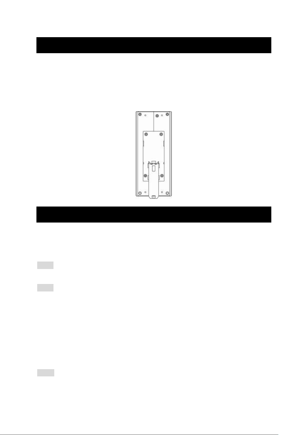
DIN Rail Mounting
Fix the DIN rail attachment plate to the back panel of the Media Converter.
Installation: Place the Media Converter on the DIN rail from above using the slot. Push the
front of the Media Converter toward the mounting surface until it audibly snaps into place.
Removal: Pull out the lower edge and then remove the Media Converter from the DIN rail.
Connecting to Power
Redundant DC Terminal Block Power Inputs or DC Jack Power Input:
47-57VDC Jack
Step 1: Connect the supplied AC to DC power adapter to the receptacle on the topside of
the switch.
Step 2: Connect the power cord to the AC to DC power adapter and attach the plug into a
standard AC outlet with the appropriate AC voltage.
Redundant 47-57VDC DC Terminal Block Power
Inputs
There are two pairs of power inputs for use with redundant power sources. You only need
to have one power input connected to run the switch.
Step 1: Connect the DC power cord to the plug-able terminal block on the switch, and
then plug it into a standard DC outlet.
User Manual Page 17
Page 18
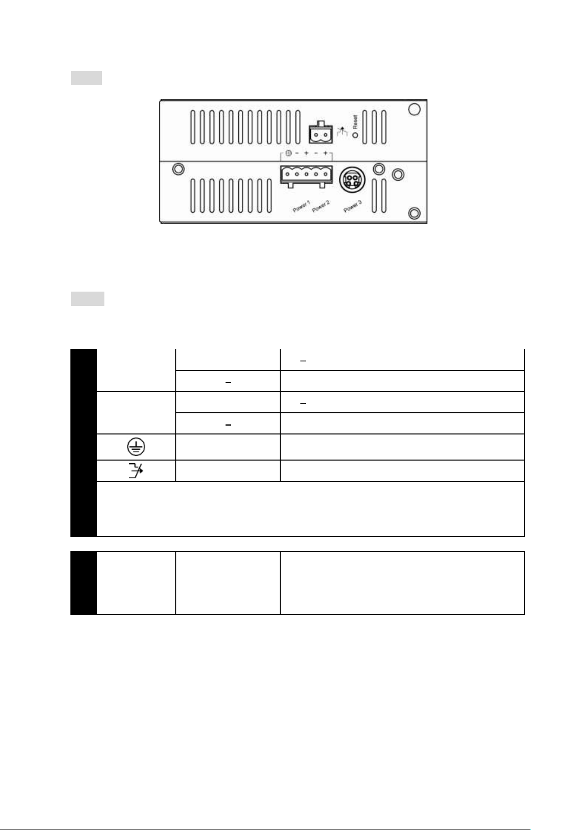
Step 2: Disconnect the power cord if you want to shut down the switch.
Terminal Block
PW1
+
47 57VDC
Power Ground
PW2
+
47 57VDC
Power Ground
Earth Ground
Relay Output
1A @ 250VAC
Relay Alarm warning signal disable for following:
3. The relay contact closes if Power1 and Power2 are both failed but Power3 on
4. The relay contact closes if Power3 is failed but Power1 and Power2 are both on
DC Jack
PW3
DC Jack
47 to 57VDC
Back View
Alarms for Power Failure
Step 1: There are two pins on the terminal block used for power failure detection. It
provides the normally closed output when the power source is active. Use this as a
dry contact application to send a signal for power failure detection.
Special note:
The relay output is normal open position when there is no power to the switch.
Please do not connect any power source to this terminal to prevent shorting your
power supply.
User Manual Page 18
Page 19
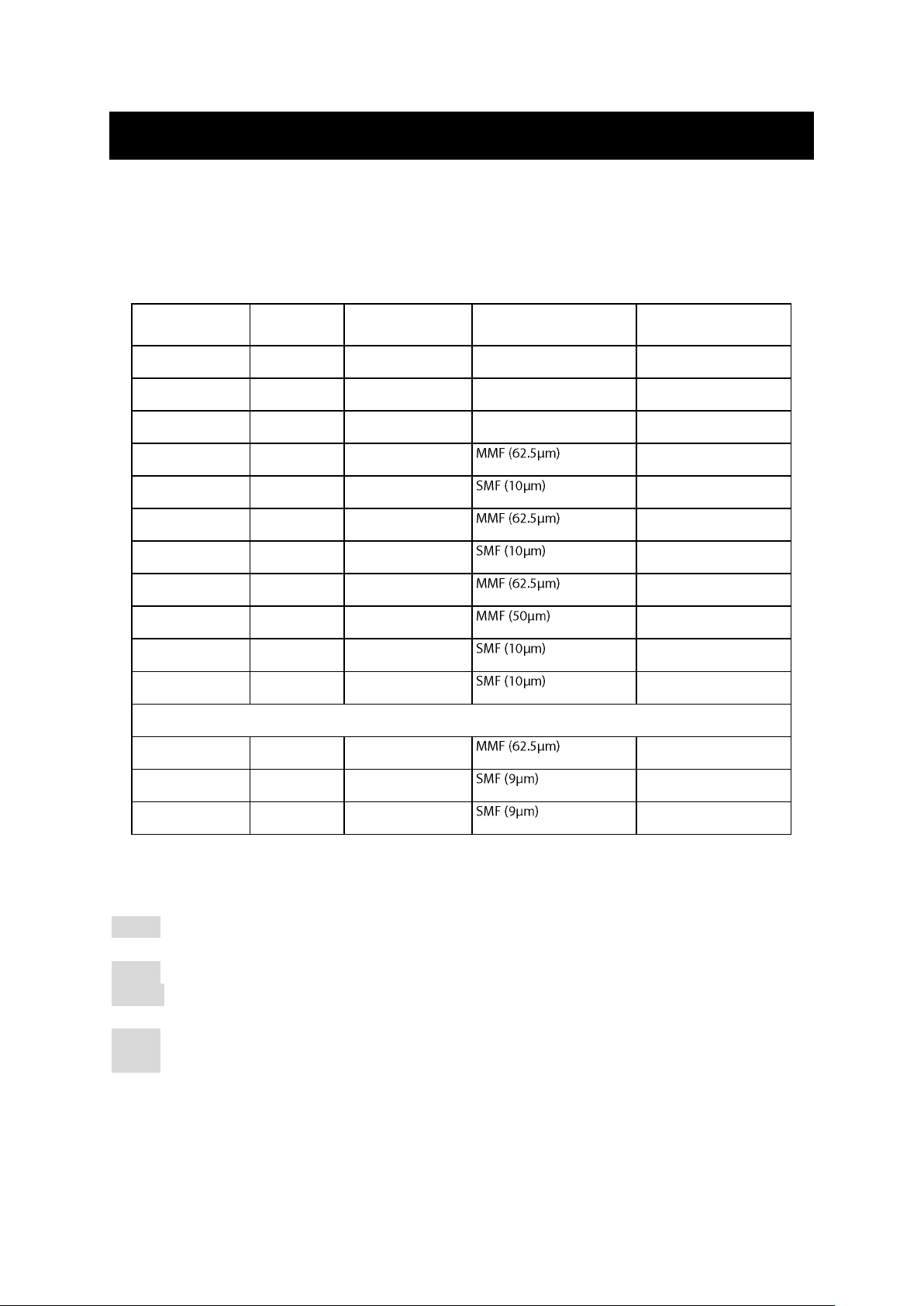
Connecting to Your Network
Speed
Connector
Port Speed
Half/Full Duplex
Cable
Max. Distance
10Base-T
RJ-45
10/20 Mbps
2-pair UTP/STP Cat. 3, 4, 5
100 m
100Base-TX
RJ-45
100/200 Mbps
2-pair UTP/STP Cat. 5
100 m
1000Base-T
RJ-45
2000 Mbps
4-pair UTP/STP Cat. 5
100 m
100Base-FX
ST, SC
200 Mbps
2 km
100Base-FX
ST, SC
200 Mbps
20, 40, 75, 100 km
100Base-BX
SC
200 Mbps
2, 5 km
100Base-BX
SC
200 Mbps
20, 40 km
1000Base-SX
SC
2000 Mbps
220 m, 2 km
1000Base-SX
SC
2000 Mbps
550 m
1000Base-LX
SC
2000 Mbps
10, 20, 50 km
1000Base-BX
SC
2000 Mbps
20, 40 km
SFP
1000Base-SX
Duplex LC
2000 Mbps
550 m, 2 km
1000Base-LX
Duplex LC
2000 Mbps
10, 40, 60 km
1000Base-BX
Duplex LC
2000 Mbps
70 km
Cable Type & Length
It is necessary to follow the cable specifications below when connecting the switch to your network. Use appropriate
cables that meet your speed and cabling requirements.
Cable Specifications
Cabling
Step 1: First, ensure the power of the switch and end devices are turned off.
<Note> Always ensure that the power is off before any installation.
Step 2: Prepare cable with corresponding connectors for each type of port in use.
Step 3: Consult Cable Specifications Table on previous page for cabling requirements
Step 4: Connect one end of the cable to the switch and the other end to a desired device.
Step 5: Once the connections between two end devices are made successfully, turn on the
User Manual Page 19
based on connectors and speed.
power and the switch is operational.
Page 20

Switch Management
This chapter explains the methods that you can use to configure management access to
the switch. It describes the types of management applications and the communication
and management protocols that deliver data between your management device
(workstation or personal computer) and the system. It also contains information about
port connection options.
This chapter covers the following topics:
Management Access Overview
Key Concepts
Key Guidelines for Implementation
Web Management Access
Administration Console Access
SNMP Access
Standards, Protocols, and Related Reading
Management Access Overview
The switch gives you the flexibility to access and manage the switch using any or all of the
following methods.
The web browser interface and administration console (CLI) support are embedded in the
switch software and are available for immediate use.
User Manual Page 20
Page 21

Administration Console (CLI)
The administration console is an internal, character-oriented, Command Line Interface (CLI)
for performing system administration such as displaying statistics or changing option
settings. Using this method, you can view the administration console from a terminal,
personal computer, Apple Macintosh, or workstation co
port. There are two ways to use this management method: direct access or modem access.
The following sections describe these methods.
Direct Access
Direct access to the administration console is achieved by directly connecting a terminal
or a PC equipped with a terminal-emulation program (such as HyperTerminal) to the
switch console port.
When using the management method, configure the terminal-emulation program to use
the following parameters (you can change these settings after login):
[DEFAULT PARAMETERS]
115,200bps
8 data bits
No parity
1 stop bit
This management method is often preferred because you can remain connected and
monitor the system during system reboots. Also, certain error messages are sent to the
serial port, regardless of the interface through which the associated action was initiated. A
Macintosh or PC attachment can use any terminal-emulation program for connecting to
the terminal serial port. A workstation attachment under UNIX can use an emulator such
as TIP.
Modem Access
external modem attached to the console port. The switch management program provides
Console Port screen, accessible from the Basic Management screen that lets you
configure parameters for modem access.
When you have configured the external modem from the administration console, the
switch transmits characters that you have entered as output on the modem port. The
switch echoes characters that it receives as input on the modem port to the current
administration console session. The console appears to be directly connected to the
external modem.
User Manual Page 21
Page 22

Web Management
The switch provides a browser interface that lets you configure and manage the switch
remotely.
applications directly in your web browser by entering the IP address of the switch. You can
then use your web browser to list and manage switch configuration parameters from one
SNMP-Based Network Management
You can use an external SNMP-based application to configure and manage the switch. This
management method requires the SNMP agent on the switch and the SNMP Network
Management Station to use the same community string. This management method, in fact,
uses two community strings: the get community string and the set community string. If
the SNMP Network management station only knows the set community string, it can read
and write to the MIBs. However, if it only knows the get community string, it can only read
MIBs. The default get and set community strings for the switch are public.
Protocols
The switch supports the following protocols:
VIRTUAL TERMINAL PROTOCOLS, SUCH AS TELNET
A virtual terminal protocol is a software program, such as Telnet, that allows
you to establish a management session from a Macintosh, a PC, or a UNIX
workstation. Because Telnet runs over TCP/IP, you must have at least one IP
address configured on the switch before you can establish access to it with a
virtual terminal protocol.
<Note> Terminal emulation is different from a virtual terminal protocol in that you must
connect a terminal directly to the console port.
SIMPLE NETWORK MANAGEMENT PROTOCOL (SNMP)
SNMP is the standard management protocol for multivendor IP networks.
SNMP supports transaction-based queries that allow the protocol to format
messages and to transmit information between reporting devices and
data-collection programs. SNMP runs on top of the User Datagram Protocol
(UDP), offering a connectionless-mode service.
User Manual Page 22
Page 23

Management Architecture
All of the management application modules use the same Messaging Application
Programming Interface (MAPI). By unifying management methods with a single MAPI,
configuration parameters set using one method (e.g. console port) are immediately
displayed the other management methods (e.g. SNMP agent of web browser).
The management architecture of the switch adheres to the IEEE open standard. This
compliance assures customers that the switch is compatible with, and will interoperate
with other solutions that adhere to the same open standard.
User Manual Page 23
Page 24

SNMP & RMON Management
Remote Monitoring (RMON) capabilities.
Overview
RMON is an abbreviation for the Remote Monitoring MIB (Management Information Base).
RMON is a system defined by the Internet Engineering Task Force (IETF) document RFC
2819, which defines how networks can be monitored remotely.
RMONs typically consist of two components: an RMON probe and a management
workstation:
- The RMON probe is an intelligent device or software agent that continually
collects statistics about a LAN segment or VLAN. The RMON probe transfers
the collected data to a management workstation on request or when a
pre-defined threshold is reached.
- The management workstation collects the statistics that the RMON probe
gathers. The workstation can reside on the same network as the probe, or it
can have an in-band or out-of-band connection to the probe.
The switch provides RMON capabilities that allow network administrators to set
parameters and view statistical counters defined in MIB-II, Bridge MIB, and RMON MIB.
RMON activities are performed at a Network Management Station running an SNMP
network management application with graphical user interface.
SNMP Agent and MIB-2 (RFC 1213)
The SNMP Agent running on the switch manager CPU is responsible for:
- Retrieving MIB counters from various layers of software modules according
to the SNMP GET/GET NEXT frame messages.
- Setting MIB variables according to the SNMP SET frame message.
- Generating an SNMP TRAP frame message to the Network Management
Station if the threshold of a certain MIB counter is reached or if other trap
conditions (such as the following) are met:
User Manual Page 24
Page 25

WARM START
COLD START
LINK UP
LINK DOWN
AUTHENTICATION FAILURE
RISING ALARM
FALLING ALARM
TOPOLOGY ALARM
MIB-II defines a set of manageable objects in various layers of the TCP/IP protocol suites.
MIB-II covers all manageable objects from layer 1 to layer 4, and, as a result, is the major
SNMP MIB supported by all vendors in the networking industry. The switch supports a
complete implementation of SNMP Agent and MIB-II.
RMON MIB (RFC 2819) and Bridge MIB (RFC 1493)
The switch provides hardware-based RMON counters in the switch chipset. The switch
manager CPU polls these counters periodically to collect the statistics in a format that
complies with the RMON MIB definition.
RMON Groups Supported
The switch supports the following RMON MIB groups defined in RFC 2819:
- RMON Statistics Group maintains utilization and error statistics for the
switch port being monitored.
- RMON History Group gathers and stores periodic statistical samples from
the previous Statistics Group.
- RMON Alarm Group allows a network administrator to define alarm
thresholds for any MIB variable. An alarm can be associated with Low
Threshold, High Threshold, or both. A trigger can trigger an alarm when the
value of a specific MIB variable exceeds a threshold, falls below a threshold,
or exceeds or falls below a threshold.
- RMON Event Group allows a network administrator to define actions
based on alarms. SNMP Traps are generated when RMON Alarms are
triggered. The action taken in the Network Management Station depends on
the specific network management application.
User Manual Page 25
Page 26
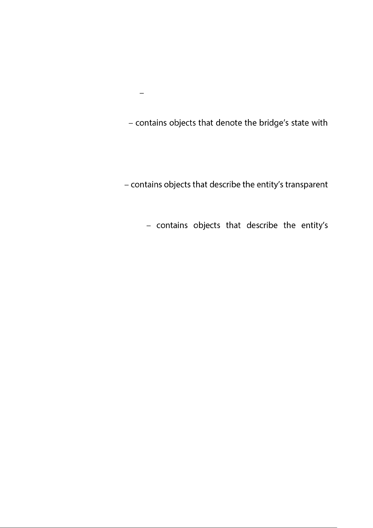
Bridge Groups Supported
The switch supports the following four groups of Bridge MIB (RFC 1493):
- The dot1dBase Group a mandatory group that contains the objects
applicable to all types of bridges.
- The dot1dStp Group
respect to the Spanning Tree Protocol. If a node does not implement the
Spanning Tree Protocol, this group will not be implemented. This group is
applicable to any transparent only, source route, or SRT bridge that
implements the Spanning Tree Protocol.
- The dot1dTp Group
bridging status. This group is applicable to transparent operation only and
SRT bridges.
- The dot1dStatic Group
destination-address filtering status. This group is applicable to any type of
bridge which performs destination-address filtering.
Page 27
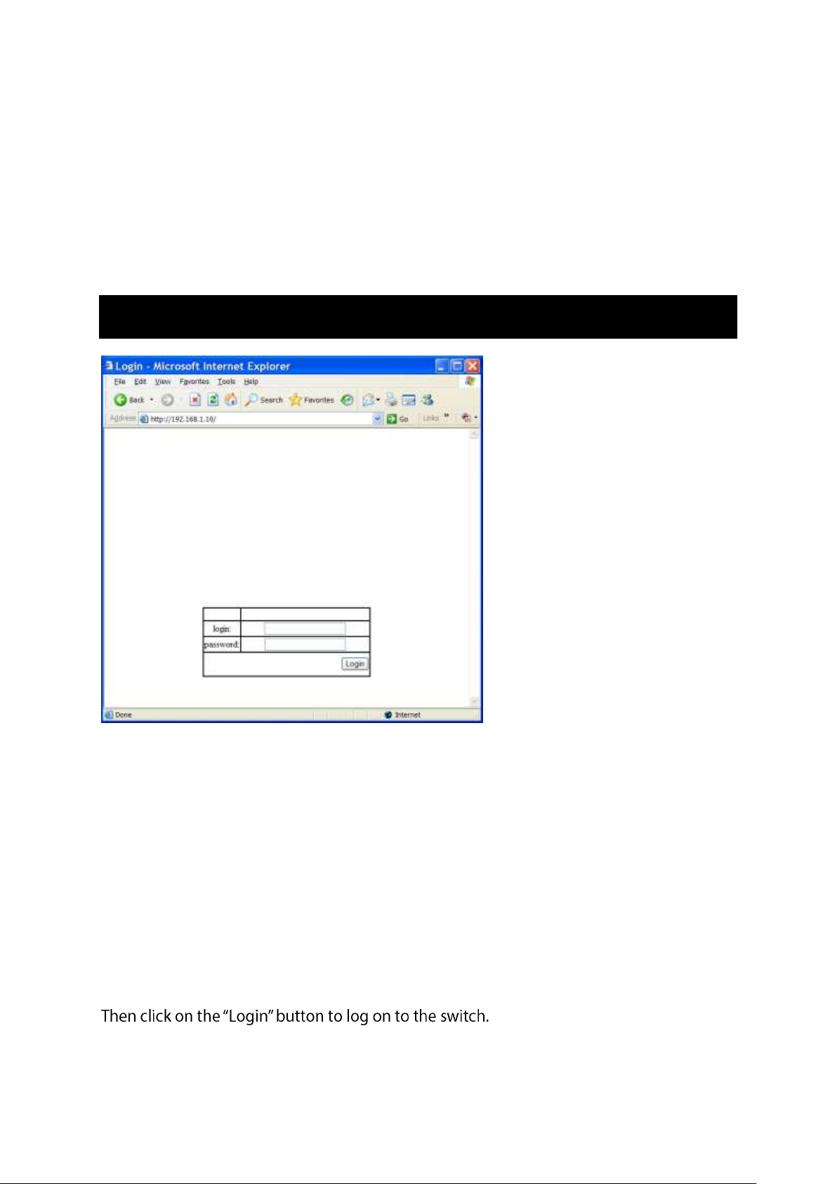
Web-Based Browser Management
The switch provides a web-based browser interface for configuring and managing the
switch. This interface allows you to access the switch using a preferred web browser.
This chapter describes how to configure the switch using its web-based browser interface.
Logging on to the switch
SWITCH IP ADDRESS
In your web browser, specify the IP address of the switch. Default IP address is
192.168.1.10.
LOGIN
Enter the factory default login ID: root.
PASSWORD
Enter the factory default password (no password).
Or enter a user-defined password if you followed the instructions later and changed the
factory default password.
User Manual Page 27
Page 28
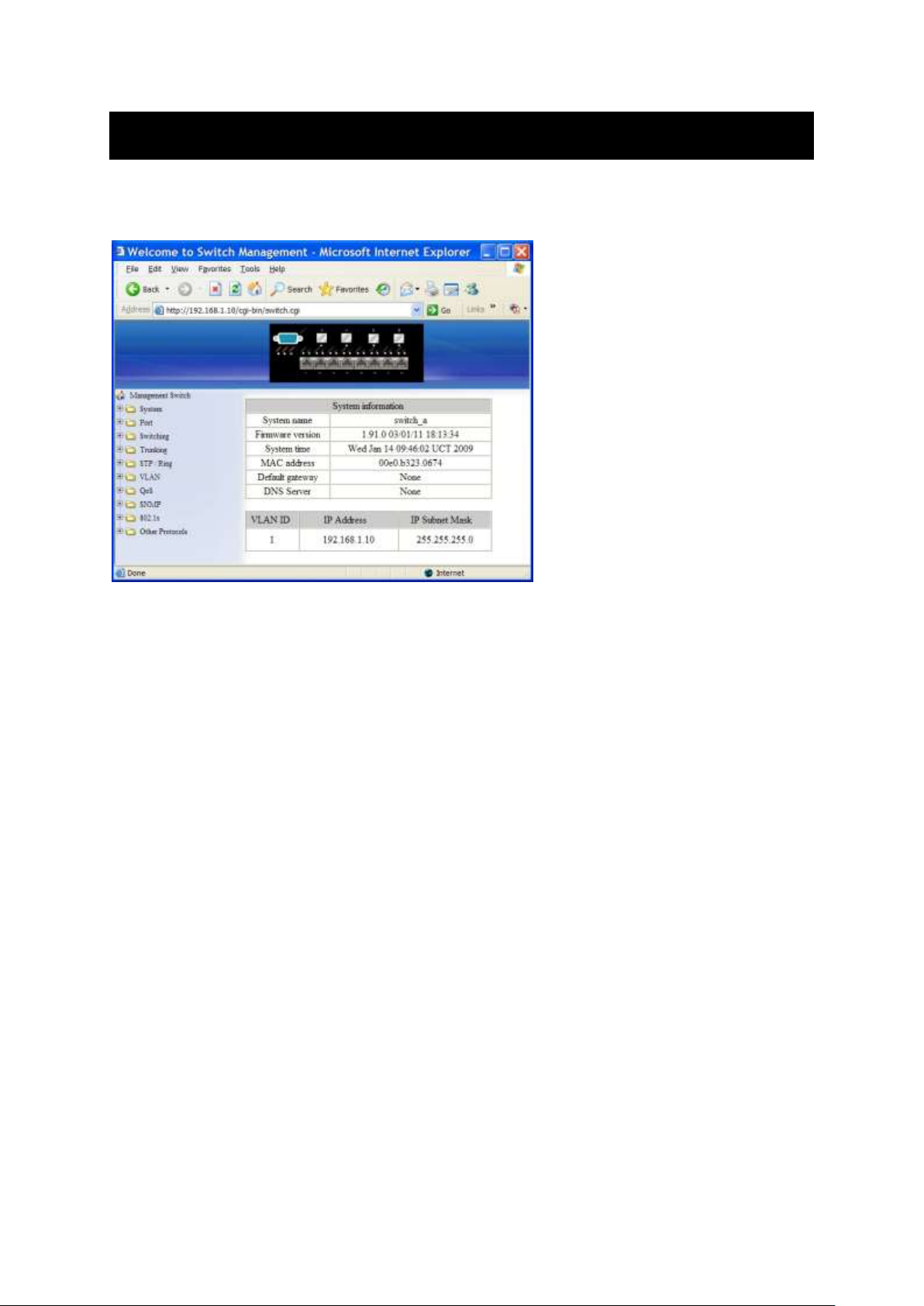
Understanding the Browser Interface
The web browser interface provides groups of point-and-click buttons at the left field of
the screen for configuring and managing the switch.
SYSTEM
System Information, System Name/Password, IP Address, ARP Table, Route
Table, Save Configuration, Firmware Upgrade, Alarm Setting, Reboot, Logout
PORT
Configuration, Port Status, Rate Control, RMON Statistics, Per Port Vlan
Activities
SWITCHING
Bridging, Static MAC Entry, Port Mirroring, PoE, PoE Scheduling
TRUNKING
Port Trunking
STP / RING
Global Configuration, RSTP Port Setting, MSTP Properties, MSTP Instance Setting, MSTP
Port Setting, Ring Setting
VLAN
VLAN Mode Setting, 802.1Q VLAN Setting, 802.1Q Port Setting, Port Based
VLAN
User Manual Page 28
Page 29

QOS
Global Configuration, 802.1p Priority, DSCP
SNMP
SNMP General Setting, SNMP v1/v2c, SNMP v3
802.1X
Radius Configuration, Port Authentication
OTHER PROTOCOLS
GVRP, IGMP Snooping, NTP
User Manual Page 29
Page 30
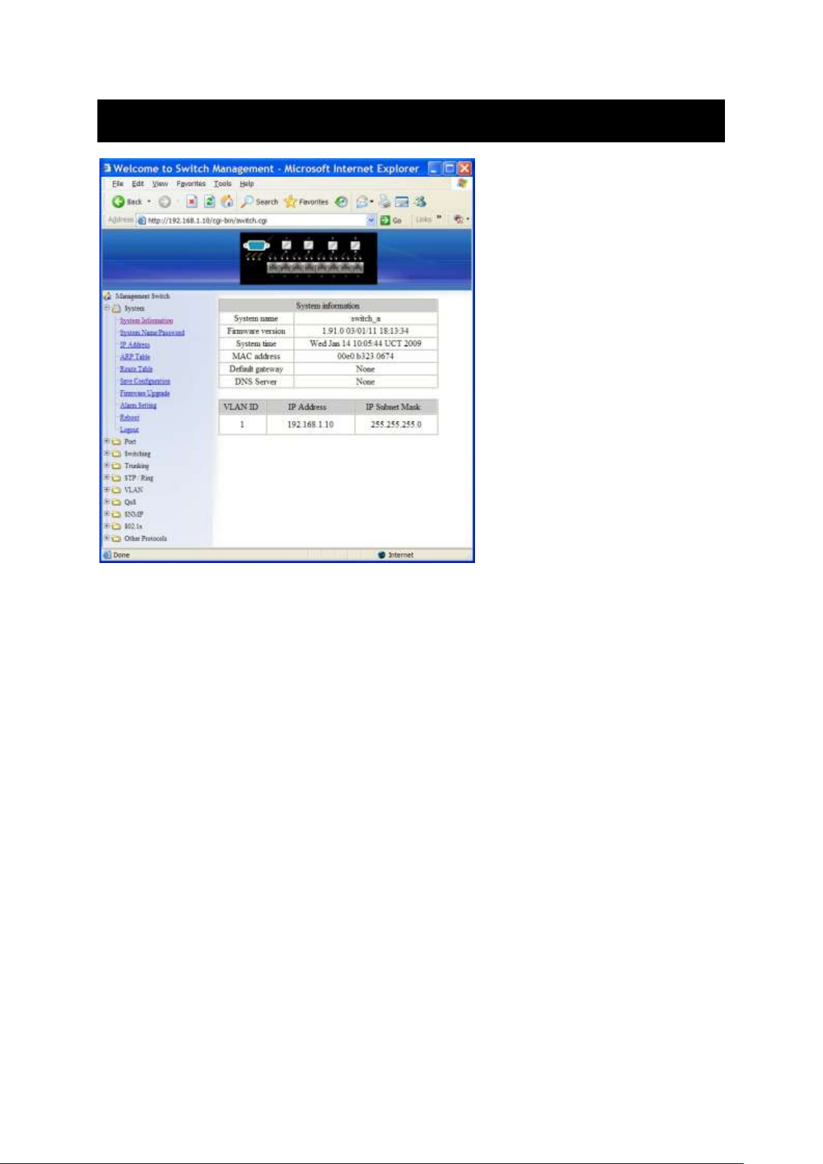
System
System Information
The System name, Firmware version, System time, MAC address, Default gateway, DNS
Server, VLAN ID, IP Address, and IP Subnet Mask of Switch.
User Manual Page 30
Page 31
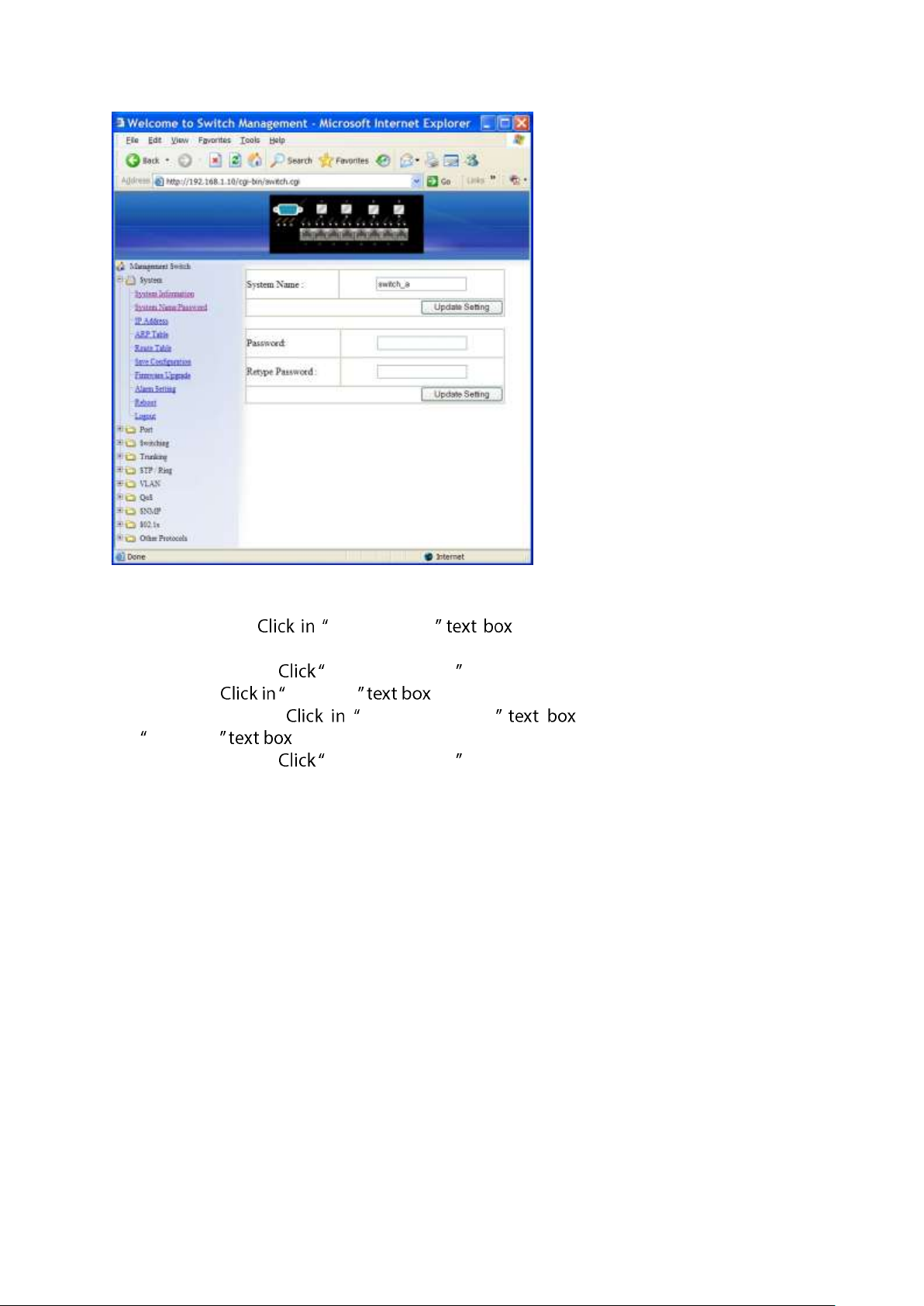
System Name/Password
1. System Name: System Name . Type a system name if it is blank, or
replace the current system name with a new one.
2. Updating setting: Updating setting button to update your settings.
3. Password: Password . Type a password.
4. Retype Password: Retype Password . Type the same password in
Password again to verify it.
5. Updating setting: Updating setting button to update your settings.
User Manual Page 31
Page 32
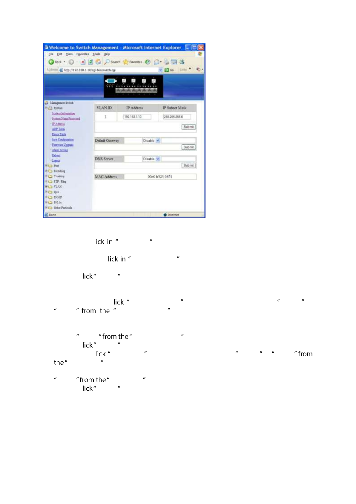
IP Address
1. IP Address: C IP Address text box and type a new address to change the IP
Address.
2. IP Subnet Mask: C IP Subnet Mask text box and type a new address to change
the IP Subnet Mask.
3. Submit: C Submit button when you finished these selections.
4. You need to enter the new IP address on the browser and reconnect to the switch after
IP or subnet mask are changed.
5. Default Gateway: C Default Gateway drop-down menu to choose Disable or
Enable Default Gateway drop-down list to disable or enable Default
Gateway Setting for the switch.
Click the text box and type a new address to change the Default Gateway. (Need to
choose Enable Default Gateway drop-down menu.)
6. Submit: C Submit button when you finished Default Gateway.
7. DNS Server: C DNS Server drop-down menu to choose Disable or Enable
DNS Server drop-down list to disable or enable DNS Server Setting for the switch.
Click the text box and type a new address to change the DNS Server. (Need to choose
Enable DNS Server drop-down menu.)
8. Submit: C Submit button when you finished DNS Server.
User Manual Page 32
Page 33
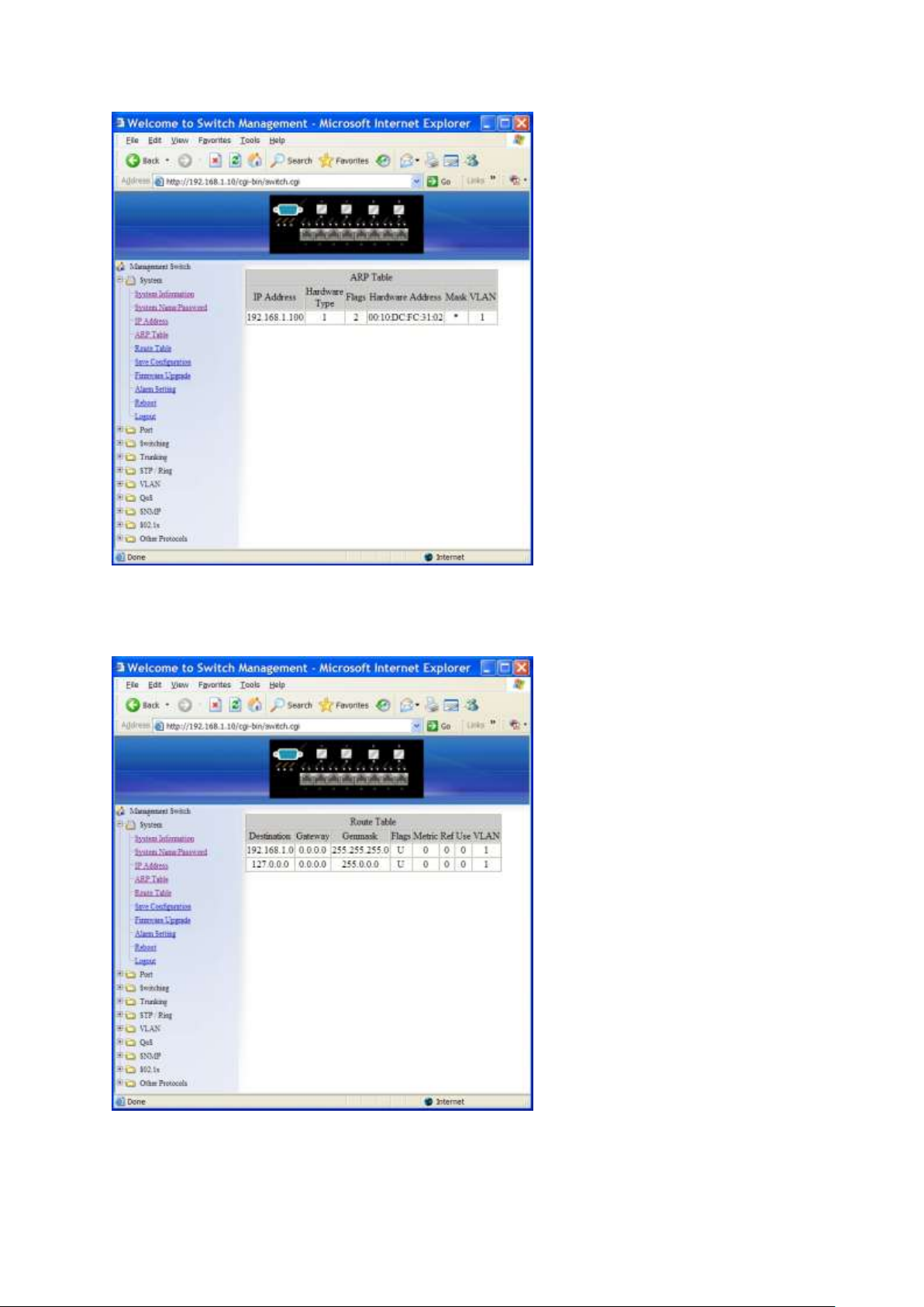
ARP Table
Click ARP Table to view ARP Table.
Route Table
Click Route Table to view Route Table.
User Manual Page 33
Page 34
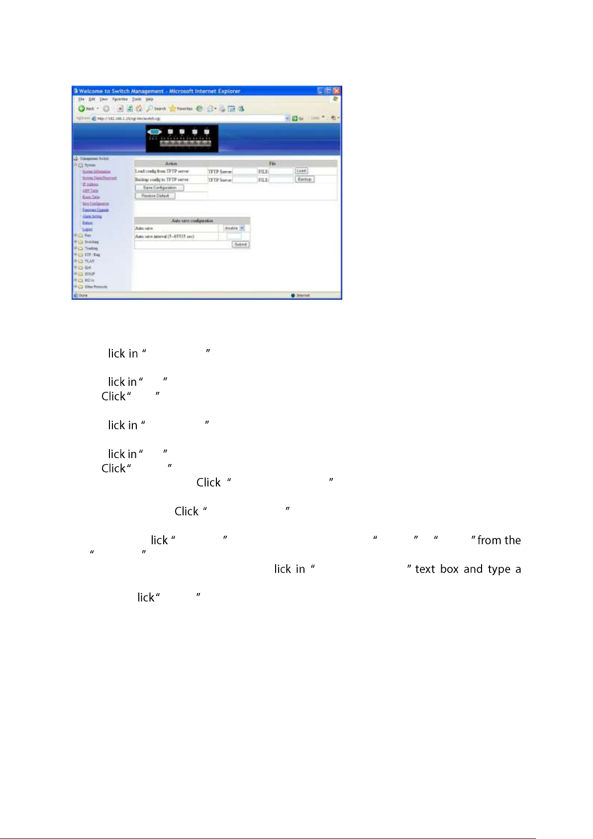
Save Configuration
1. Load config from TFTP server:
C TFTP Server text box and type the TFTP server IP address from where the
file will be obtained.
C FILE text box and type the name of the file that will be obtained.
Load button to load the file from the TFTP server.
2. Backup config to TFTP server:
C TFTP Server text box and type the TFTP server IP address to where the file
will be back upped.
C FILE text box and type the name of the file that will be back upped.
Backup button to backup the file to the TFTP server.
3. Save Configuration: Save Configuration button to save your configuration
settings.
4. Restore Default: Restore Default button to restore the default settings of the
switch.
5. Auto save: C Auto save drop-down menu to choose Disable or Enable
Auto save drop-down list to disable or enable Auto save for the switch.
6. Auto save interval (5~65536 sec): C Auto save interval
decimal number between 5 and 65536.
7. Submit: C Submit button when you finished Auto save configuration.
User Manual Page 34
Page 35
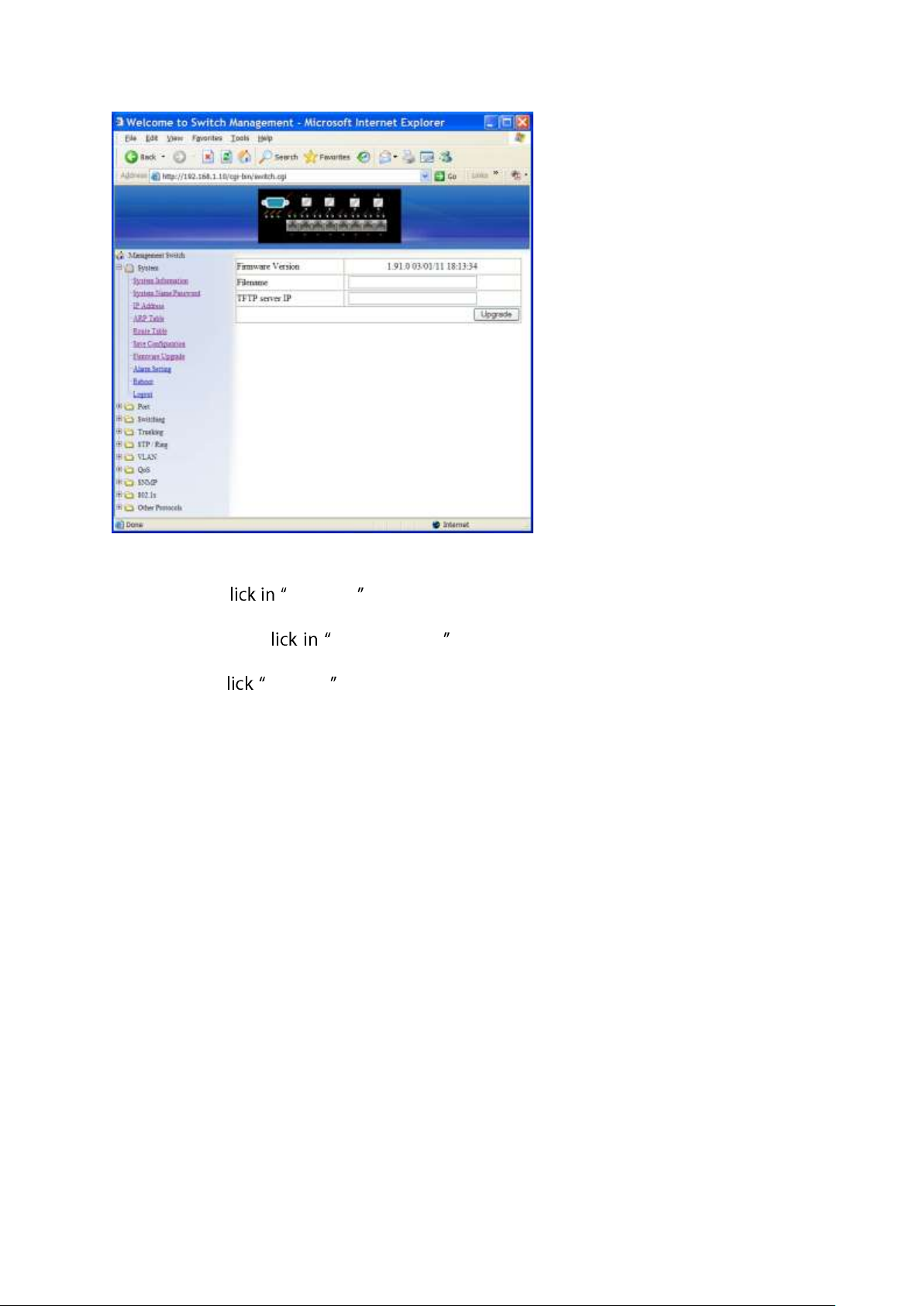
Firmware Upgrade
1. Filename: C Filename text box and type the name of the file that you intend to
upgrade it to the switch.
2. TFTP server IP: C TFTP server IP text box and type the TFTP server IP address
from where the file will be obtained.
3. Upgrade: C upgrade button to upgrade firmware to the switch. Please follow the
message on the screen during the firmware upgrade process. Do not turn off the
power or perform other functions during this period of time. Reboot the switch after
completing the upgrade process.
User Manual Page 35
Page 36

Please follow the message on the screen during the firmware upgrade process. Do not
turn off the power or perform other functions during this period of time.
User Manual Page 36
Page 37
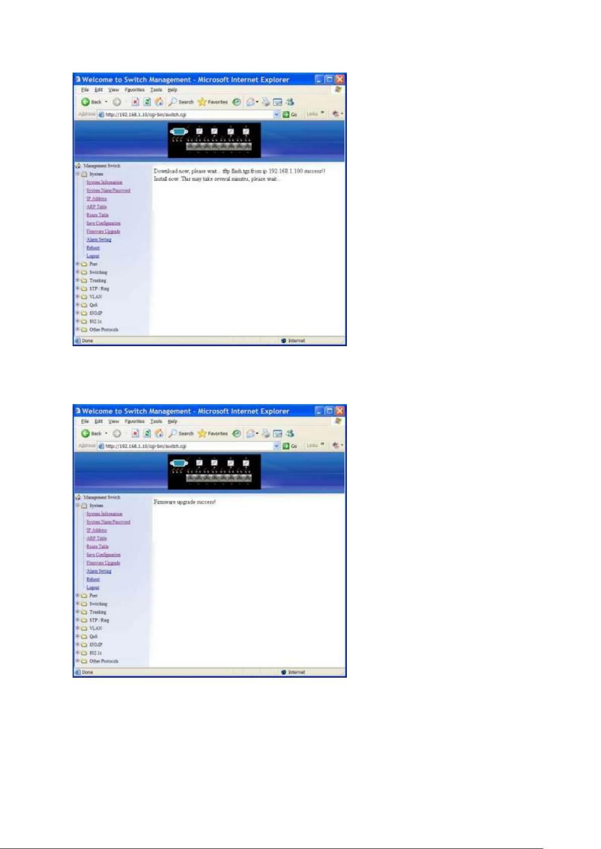
Firmware has been upgraded successfully to the switch. Reboot the switch after
completing the upgrade process.
User Manual Page 37
Page 38
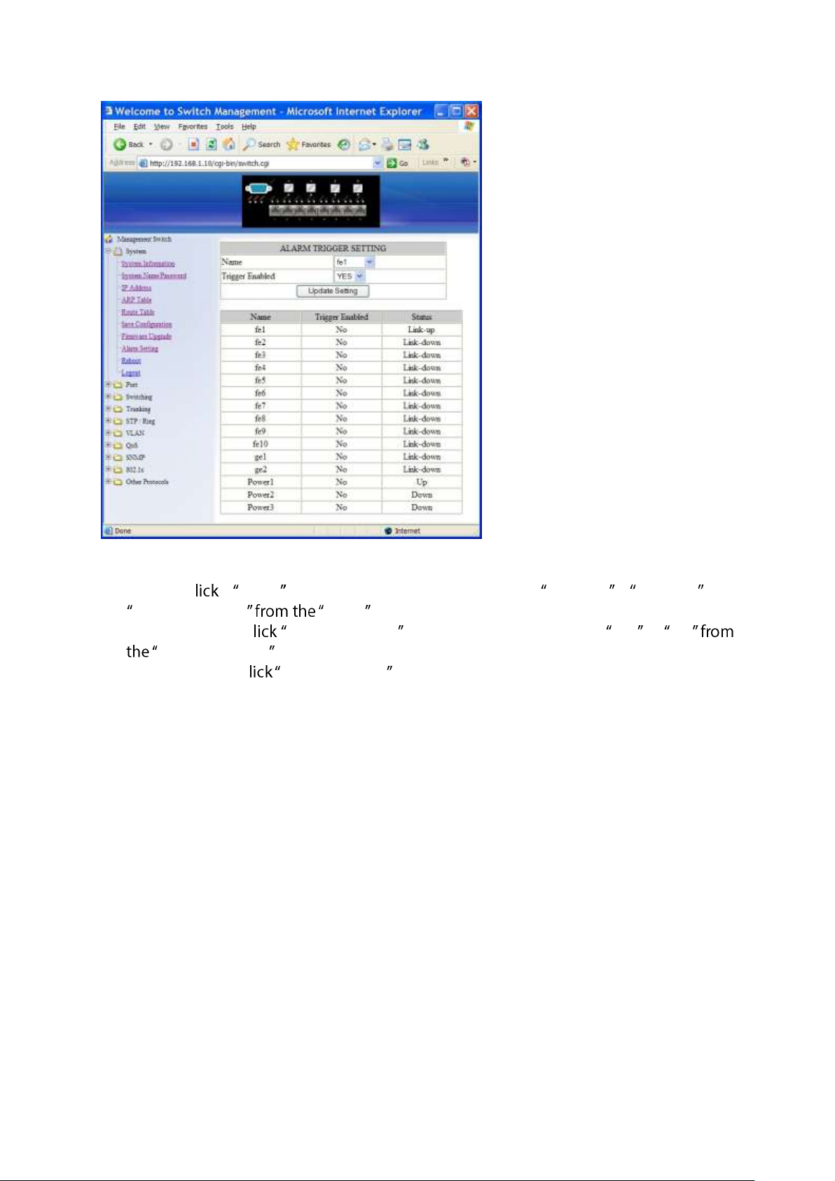
Alarm Setting
1. Name: C Name drop-down menu to choose fe1~fe10, ge1~ge2, or
Power1~Power3 Name drop-down list.
2. Trigger Enabled: C Trigger Enabled drop-down menu to choose YES or NO
Trigger Enabled drop-down list to enable or disable Trigger.
3. Update Setting: C Update Setting button to update settings to the switch.
User Manual Page 38
Page 39
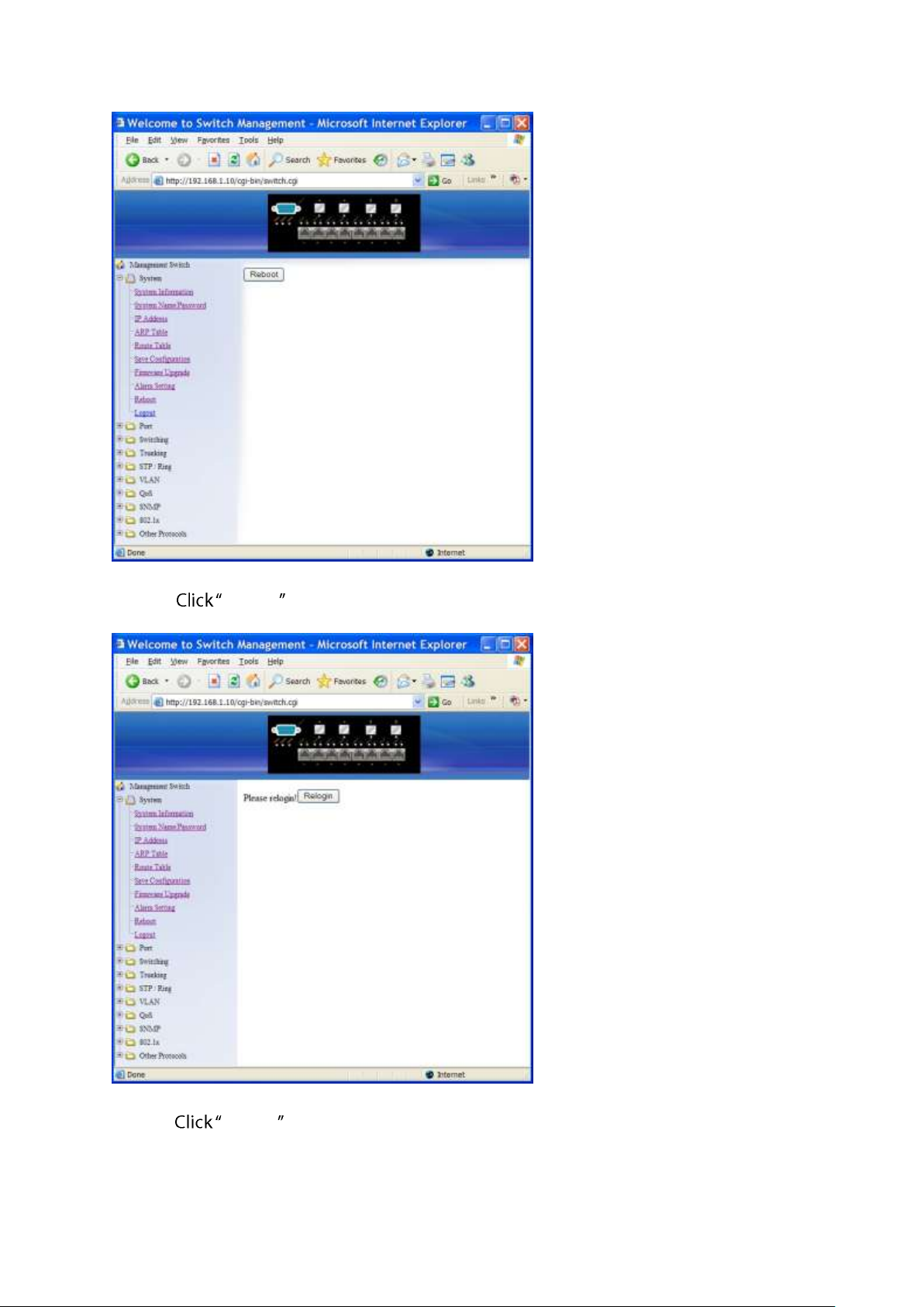
Reboot
Reboot: Reboot button to restart the switch.
Logout
Logout: Logout button to logout of the switch.
User Manual Page 39
Page 40
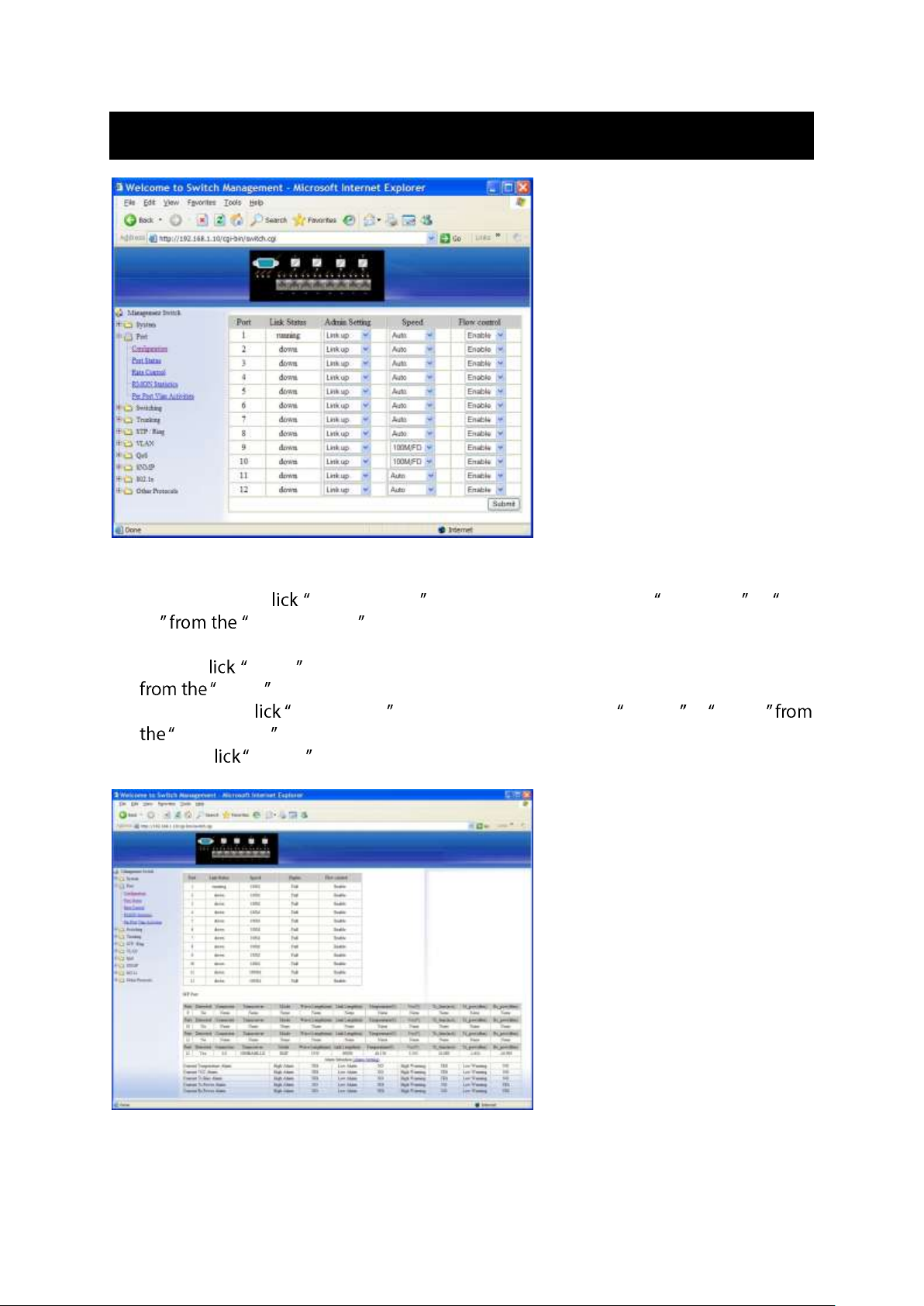
Port
Configuration
1. Admin Setting: C Admin Setting drop-down menu to choose Link down or Link
up Admin Setting drop-down list to disable or enable Admin Setting for the
port.
2. Speed: C Speed drop-down menu to change the line speed and duplex settings
Speed drop-down list for the port.
3. Flow control: C Flow control drop-down menu to choose Disable or Enable
Flow control drop-down list to disable or enable Flow control for the port.
4. Submit: C Submit button when you finished configurations.
User Manual Page 40
Page 41
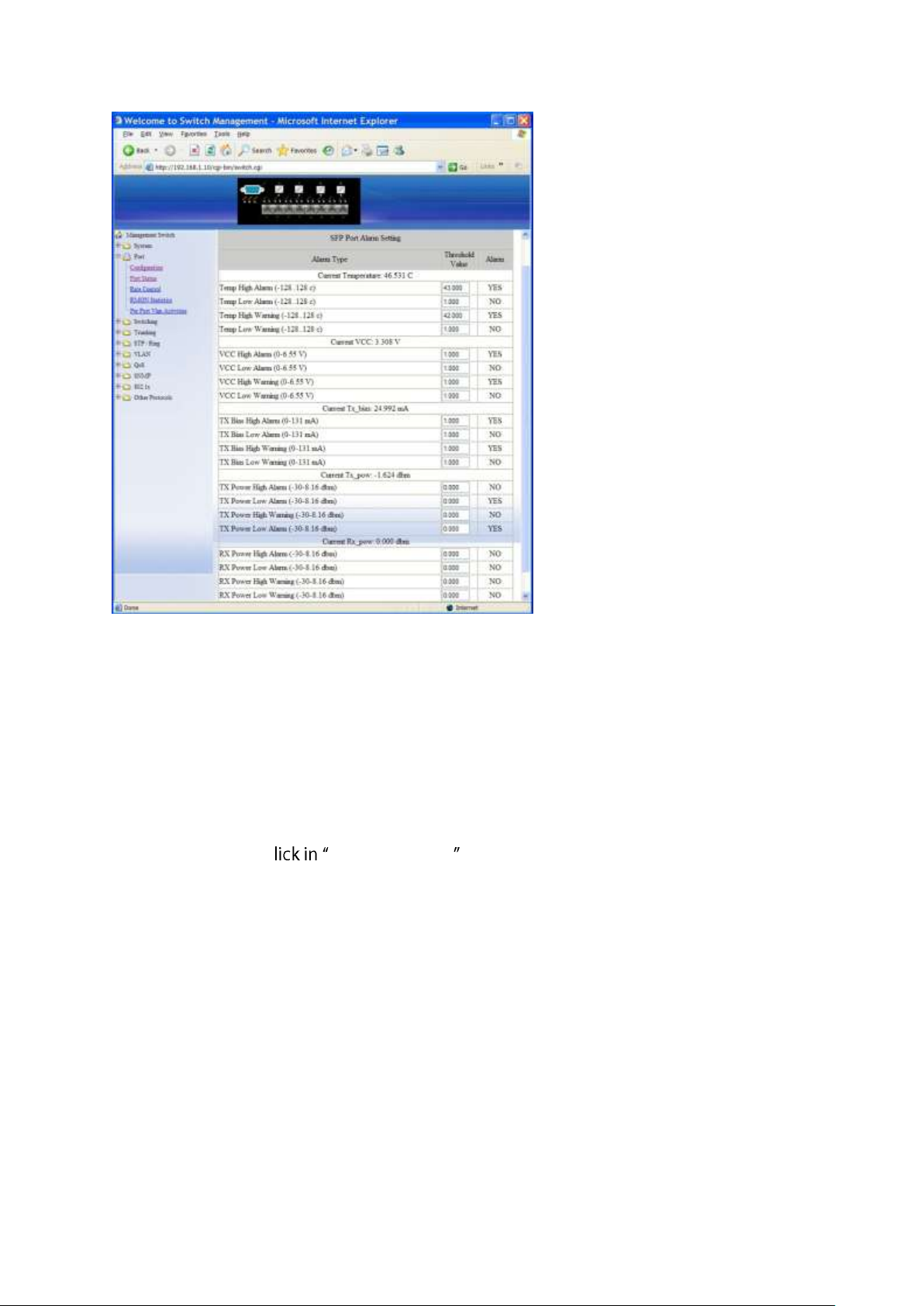
Port Status
View the Link Status, Speed, Duplex, and Flow control status for all ports.
SFP Port:
1. View the Detected, Connector, Transceiver, Mode, Wave Length (nm), Link Length (m),
Temperature (C), Vcc (V), Tx_bias (mA), Tx_pow (dbm), and Rx_pow (dbm) information
for SFP ports.
2. Alarm Situation: View Current Temperature Alarm, Current VCC Alarm, Current Tx Bias
Alarm, Current Tx Power Alarm, and Current Rx Power Alarm.
3. Alarm Setting: C Threshold Value text boxes and type new Threshold Values for
Temp High Alarm, Temp Low Alarm, Temp High Warning, Temp Low Warning, VCC
High Alarm, VCC Low Alarm, VCC High Warning, VCC Low Warning, TX Bias High Alarm,
TX Bias Low Alarm, TX Bias High Warning, TX Bias Low Warning, TX Power High Alarm,
TX Power Low Alarm, TX Power High Warning, TX Power Low Warning, RX Power High
Alarm, RX Power Low Alarm, RX Power High Warning, RX Power Low Warning.
User Manual Page 41
Page 42
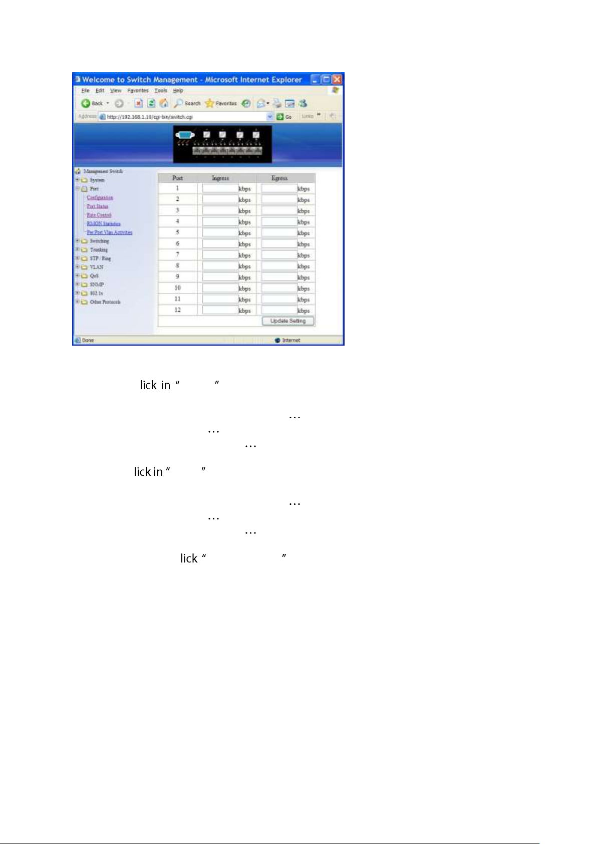
Rate Control
1. Ingress: C Ingress text box and type a new Rate to change the Ingress Rate
Control for the port.
Rate Values: 64kbps, 128kbps, 192kbps, , 1792kbps.
2Mbps, 3Mbps, 4Mbps, , 100Mbps.
104Mbps, 112Mbps, 120Mbps, , 1000Mbps.
<Note>: M = 1024k.
2. Egress: C Egress text box and type a new Rate to change the Egress Rate Control
for the port.
Rate Values: 64kbps, 128kbps, 192kbps, , 1792kbps.
2Mbps, 3Mbps, 4Mbps, , 100Mbps.
104Mbps, 112Mbps, 120Mbps, , 1000Mbps.
<Note>: M = 1024k.
3. Update setting: C Update setting button when you finished these Rate Control
settings.
User Manual Page 42
Page 43
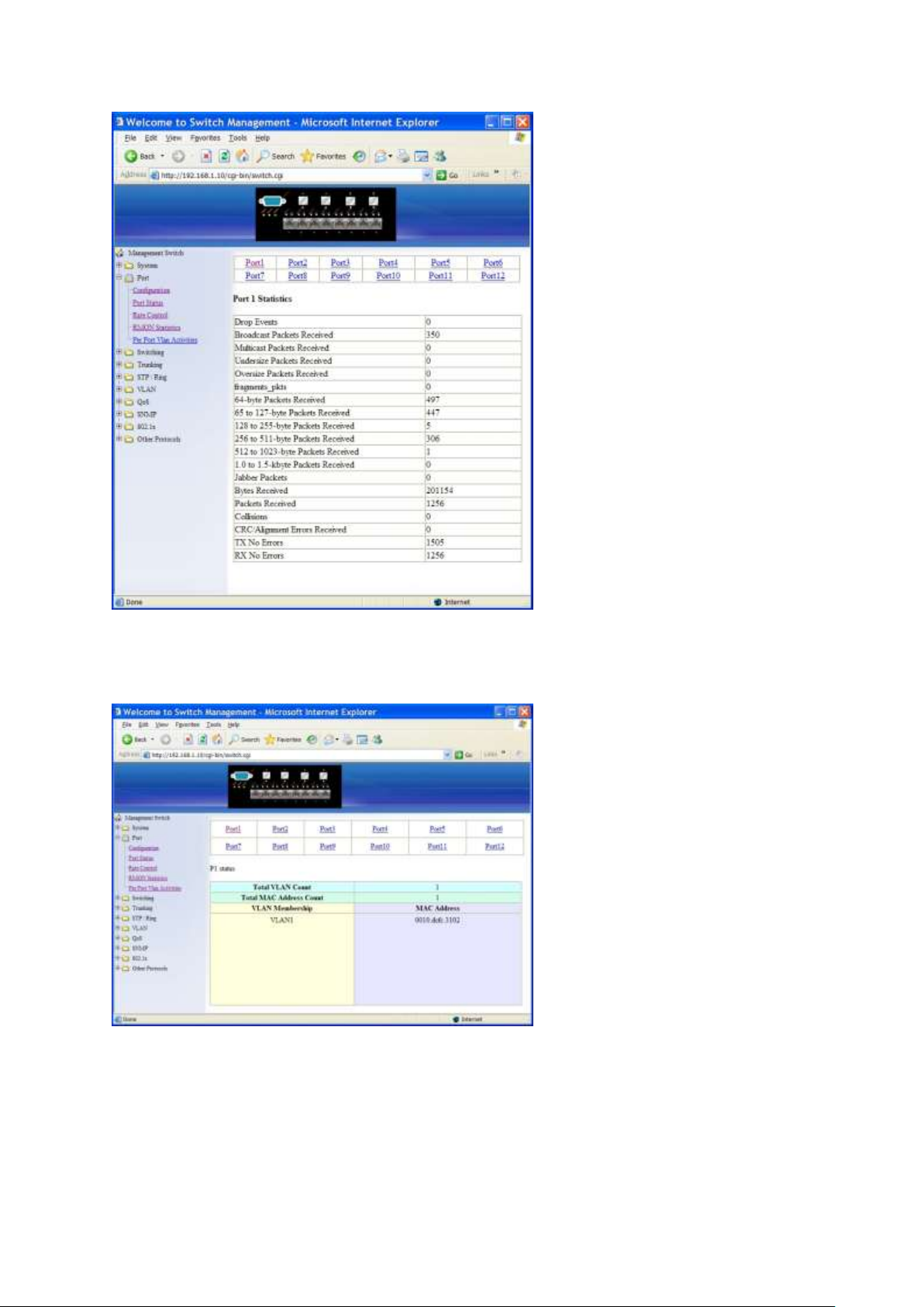
RMON Statistics
Click Port 1 ~ Port 12 to view corresponding RMON Statistics.
Per Port Vlan Activities
Click Port 1 ~ Port 12 to view corresponding vlan activities.
User Manual Page 43
Page 44
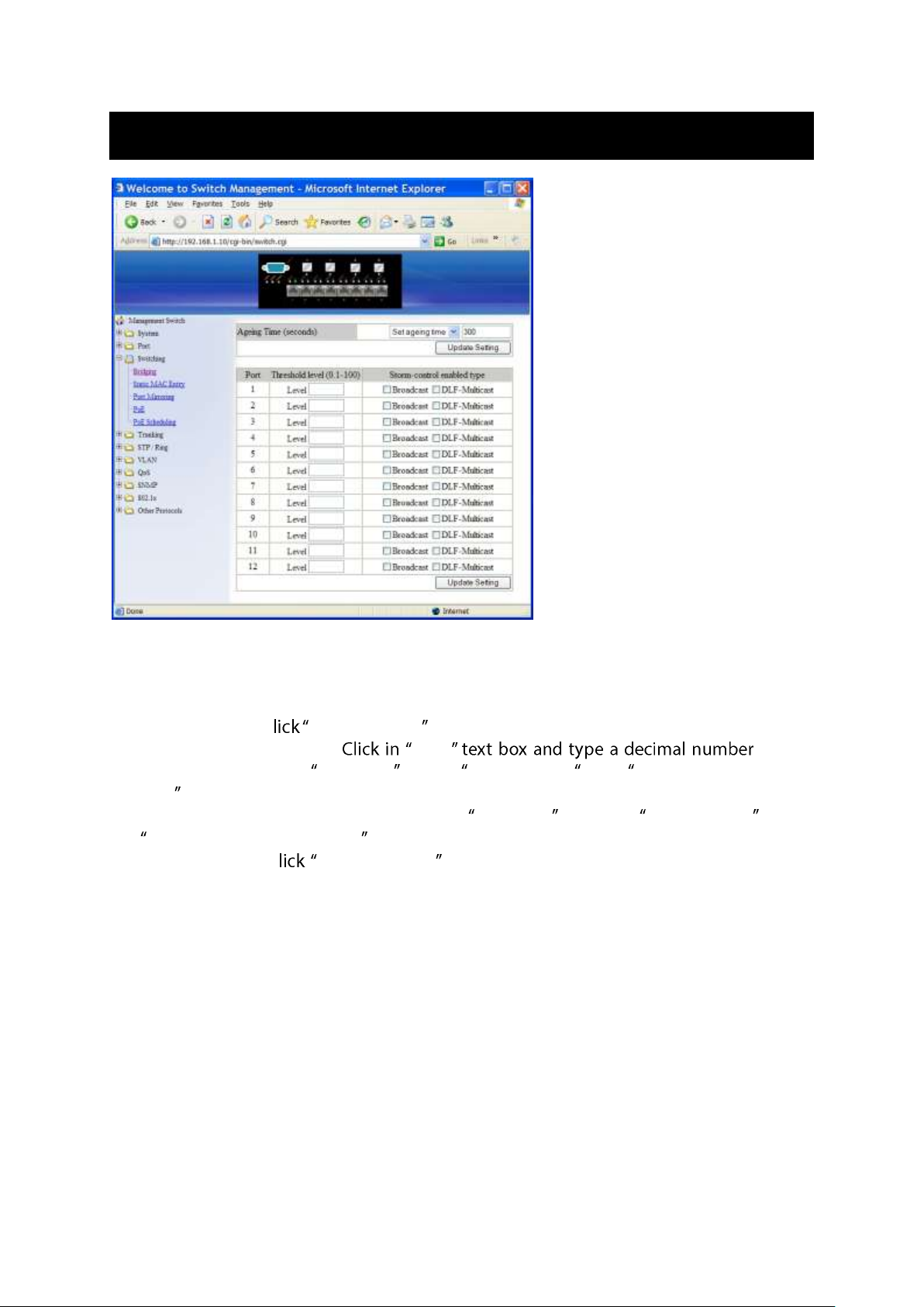
Switching
Bridging
1. Aging Time (seconds): Click the text box and type a decimal number as Bridging Aging
Time in seconds.
2. Update setting: C update setting button when you finished Aging Time settings.
3. Threshold level (0.1-100): Level for the
port. Need to choose Broadcast and/or DFL-Multicast from Storm-control enabled
type for the port. DLF (Destination Lookup Failure).
4. Storm-control enabled type: Choose Broadcast and/or DLF-Multicast from
Storm-control enabled type for the port.
5. Update Setting: C Update Setting button when you finished Threshold level and
Storm-control enabled type settings.
User Manual Page 44
Page 45
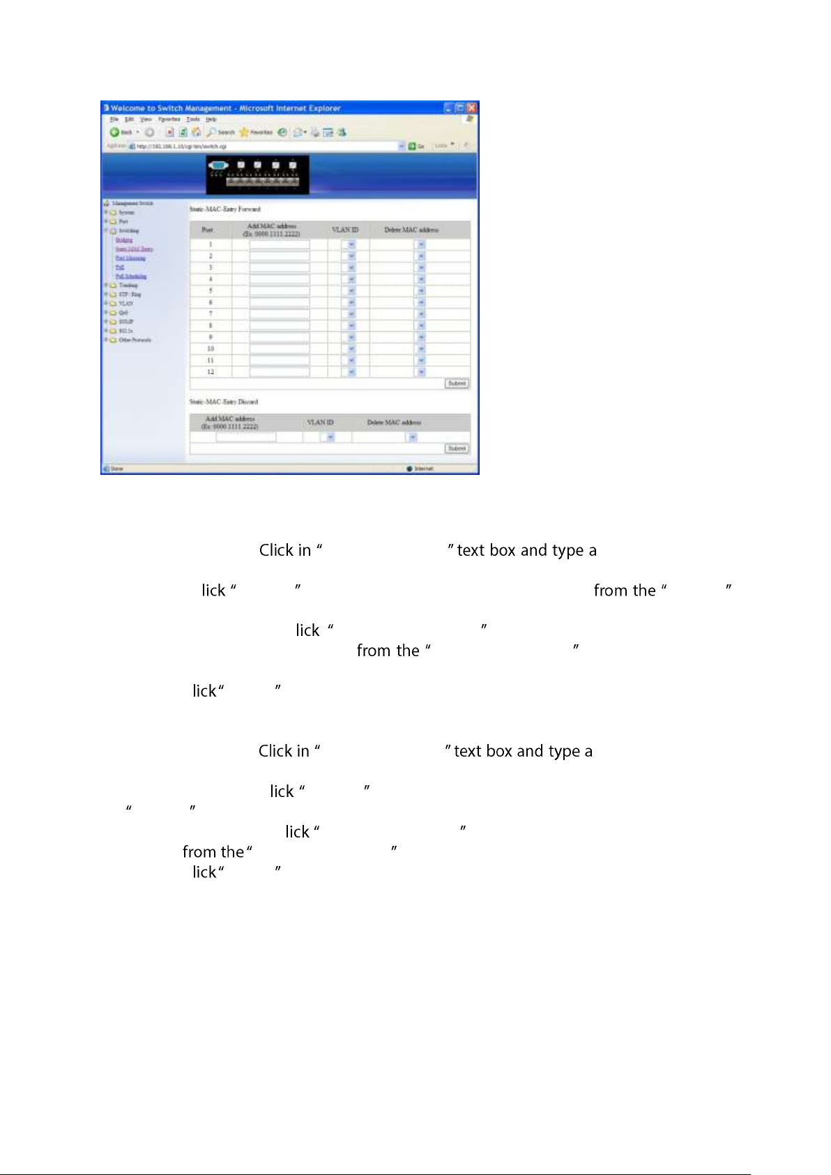
Static MAC Entry
Static-MAC-Entry Forward:
1. Add MAC address: Add MAC address locked forwarding
MAC address for the port.
2. VLAN ID: C VLAN ID drop-down menu and choose a VLAN ID VLAN ID
drop-down list.
3. Delete MAC address: C Delete MAC address drop-down menu and choose a
locked forwarding MAC address Delete MAC address drop-down list to be
deleted from the port.
4. Submit: C Submit button when you finished Static-MAC-Entry Forward settings.
Static-MAC-Entry Discard:
1. Add MAC address: Add MAC address MAC address to be
discarded for the VLAN.
2. VLAN ID: VLAN ID: C VLAN ID drop-down menu and choose a VLAN ID from the
VLAN ID drop-down list.
3. Delete MAC address: C Delete MAC address drop-down menu and choose a MAC
address Delete MAC address drop-down list to be discarded from the VLAN.
4. Submit: C Submit button when you finished Static-MAC-Entry Discard settings.
User Manual Page 45
Page 46
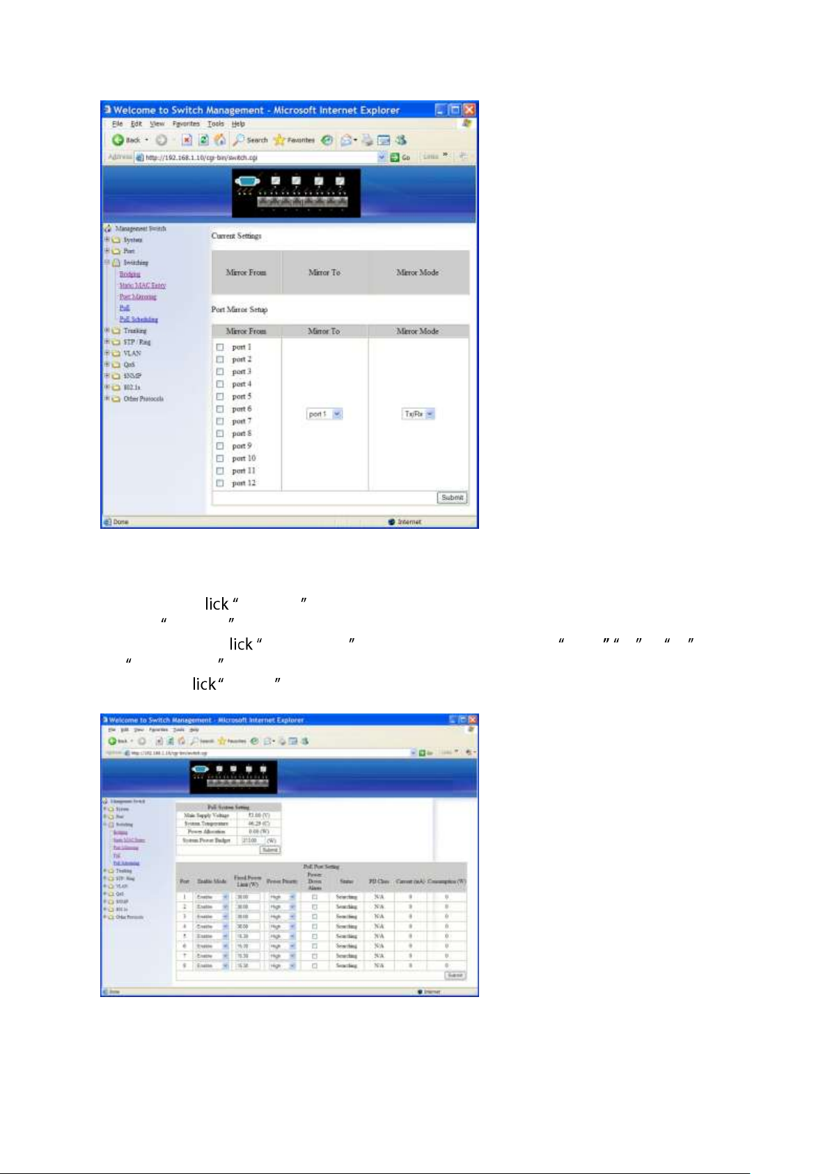
Port Mirroring
1. Mirror From: Choose Mirror From port from Port 1 ~ Port 12.
2. Mirror To: C Mirror To drop-down menu to Choose Mirror To port (Port 1 ~ Port 12)
from Mirror To drop-down list.
3. Mirror Mode: C Mirror Mode drop-down menu to Choose Tx/Rx , Tx , or Rx from
Mirror Mode drop-down list.
4. Submit: C Submit button when you finished Port Mirroring settings.
PoE
PoE System Setting:
User Manual Page 46
Page 47
1. System Power Budget: System Power Budget new system
power budget for Switch.
2. Submit: C Submit button when you finished PoE System Setting.
PoE Port Setting:
1. Enable Mode: C Enable Mode drop-down menu to choose Disable or Enable
from Enable Mode drop-down list to disable or enable this port to discover Powered
Device (PD) connected to this port.
2. Fixed Power Limit (W): C Fixed Power Limit (W) and type a new fixed
power limit for this port to provide power to PD.
3. Power Priority: C Power Priority drop-down menu to choose High , Medium, or
Low Power Priority drop-down list to determine power priority of this port.
4. Power Down Alarm: Check or uncheck Power Down Alarm to enable or disable power
down alarm on this port.
5. Submit: C Submit button when you finished PoE Port Setting.
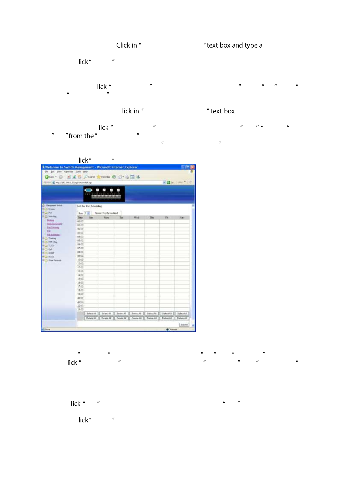
PoE Scheduling
First click on Switching from main menu. Then click on PoE from Switching. In PoE Port
Setting, c Enable Mode drop-down menu to choose Scheduling from Enable Mode
drop-down list to schedule this port to discover Powered Device (PD) connected to this
port.
PoE Per Port Setting:
1. Port: C Port drop-down menu to choose a port from Port drop-down list and
configure PoE scheduling to this port.
2. Submit: C Submit button when you finished PoE Scheduling for this port.
User Manual Page 47
Page 48
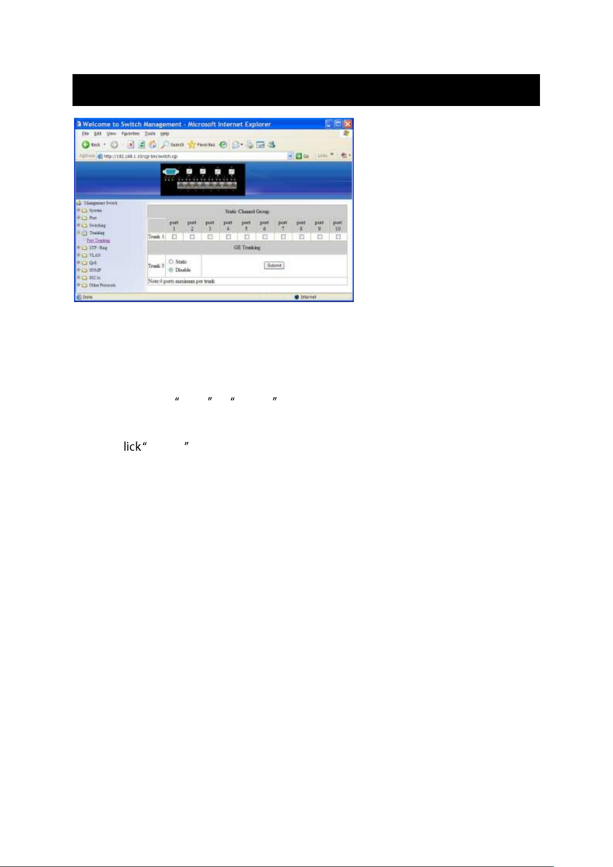
Trunking
Port Trunking
Static Channel Group:
1. Trunk 1: Click Port 1 ~ Port 10 to assign ports to Trunk 1. (Maximum 4 ports per Trunk.)
GE Trunking:
1. Trunk 3: Check Static or Disable to enable or disable Trunk 3 for Gigabit Ethernet
ports.
Submit: C Submit button when you finished Port Trunking settings.
User Manual Page 48
Page 49
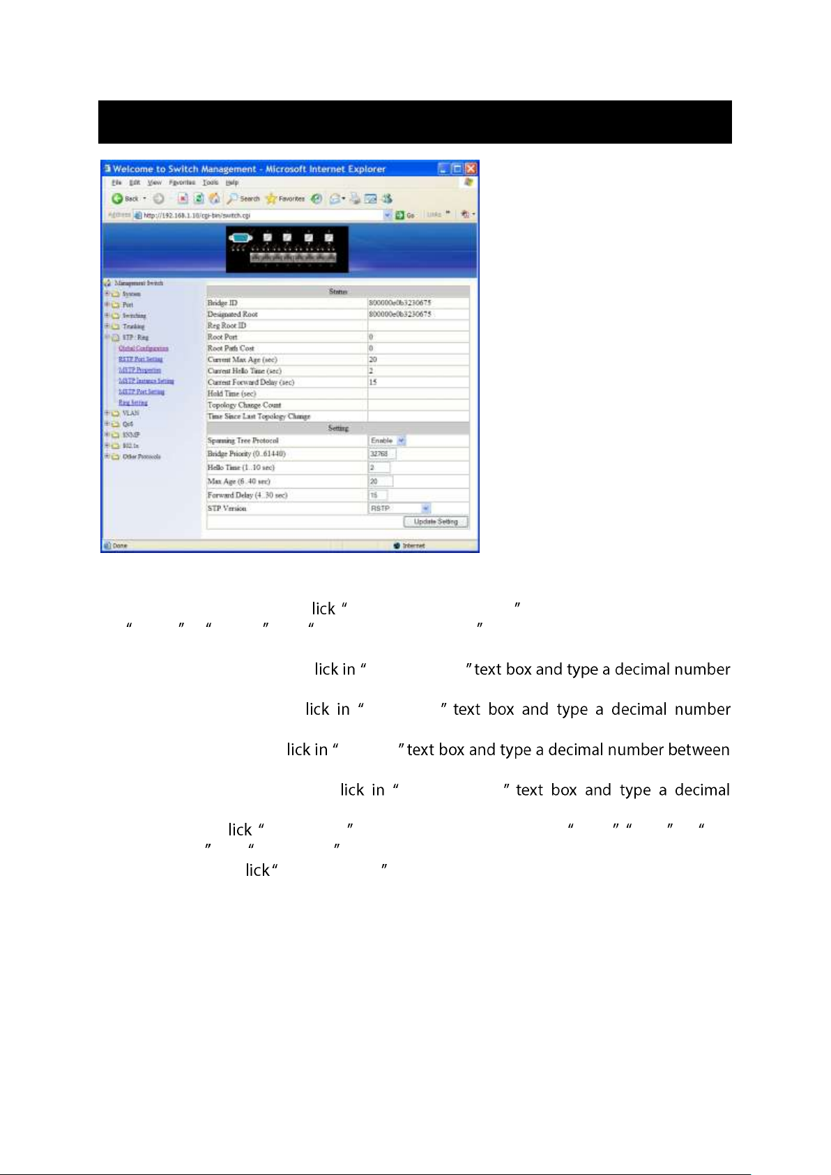
STP / Ring
Global Configuration
1. Spanning Tree Protocol: C Spanning Tree Protocol drop-down menu to Choose
Enable or Disable from Spanning Tree Protocol drop-down list to enable or disable
Spanning Tree Protocol.
2. Bridge Priority (0..61440): C Bridge Priority
between 0 and 61440.
3. Hello Time (sec) (1..9): C Hello Time
between 1 and 9.
4. Max Age (sec) (6..28): C Max Age
6 and 28.
5. Forward Delay (sec) (4..30): C Forward Delay
number between 4 and 30.
6. STP Version: C STP Version drop-down menu to choose MSTP , RSTP or STP
compatible from STP Version drop-down list.
7. Update setting: C Update setting button when you finished Global Configuration.
User Manual Page 49
Page 50
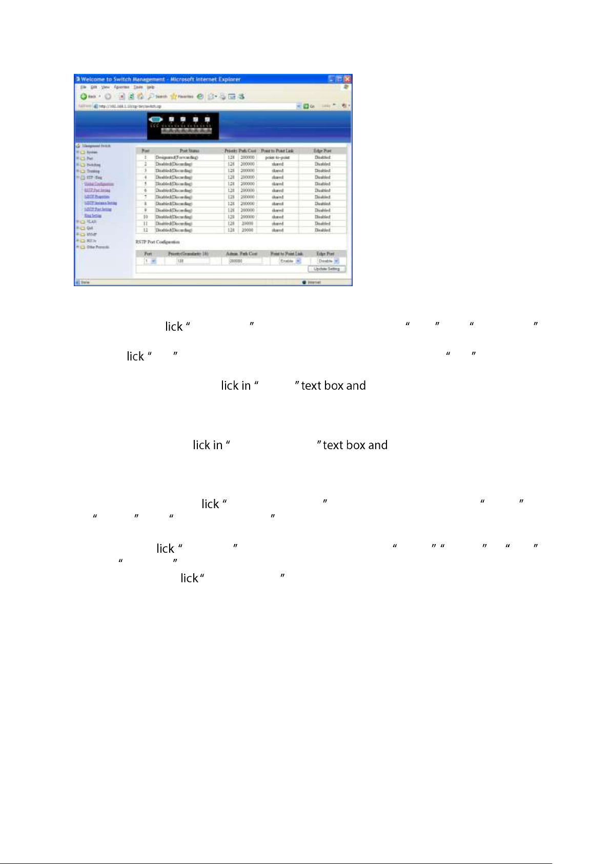
RSTP Port Setting
1. STP Version: C STP Version drop-down menu to choose RSTP from STP Version
drop-down list.
2. Port: C Port drop-down menu to Choose Port 1 ~ Port 12 from Port drop-down
list.
3. Priority(Granularity 16): C Priority enter a value between 0 and 240
to set the priority for the port. A higher priority will designate the port to forward
packets first. A lower number denotes a higher priority. This entry must be divisible by
16. The default priority setting is 128.
4. Admin. Path Cost: C Admin. Path Cost enter a value between 0 and
2000000 to set the Admin. Path Cost for the port. 0 (auto) - Setting 0 for the Admin.
Path Cost will automatically set the speed for forwarding packets to the port for
optimal efficiency. Default port cost: 100Mbps port = 200000. Gigabit port = 20000.
5. Point to Point Link: C Point to Point Link drop-down menu to Choose Enable or
Disable from Point to Point Link drop-down list to enable or disable Point to Point
Link for the port.
6. Edge Port: C Edge Port drop-down menu to Choose Enable, Disable, or Auto
from Edge Port drop-down list to set Enable, Disable, or Auto Edge Port for the port.
7. Update setting: C Update setting button when you finished RSTP Port Setting.
User Manual Page 50
Page 51
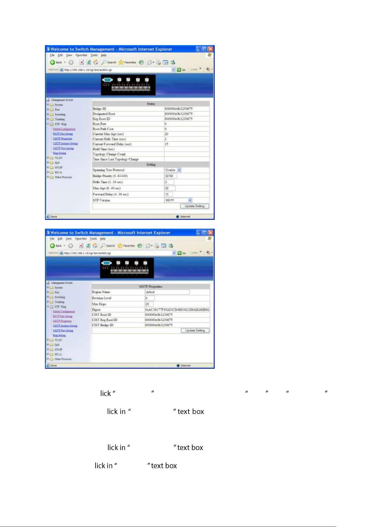
MSTP Properties
1. STP Version: C STP Version drop-down menu to choose MSTP from STP Version
drop-down list.
2. Region Name: C Region Name to create an MST region and specify a
name to it. MST bridges of a region form different spanning trees for different VLANs.
By default, each MST bridge starts with the region name as its bridge address. This
means each MST bridge is a region by itself, unless specifically added to one.
3. Revision Level: C Revision Level to specify the number for configuration
information. The default value of revision number is 0.
4. Max Hops: C Max Hops to specify the maximum allowed hops for BPDU
in an MST region. This parameter is used by all the instances of the MST. Specifying the
User Manual Page 51
Page 52
max hops for a BPDU prevents the messages from looping indefinitely in the network.
When a bridge receives a MST BPDU that has exceeded the allowed max-hops, it
discards the BPDU.
5. Update setting: C Update setting button when you finished MSTP Properties
setting.
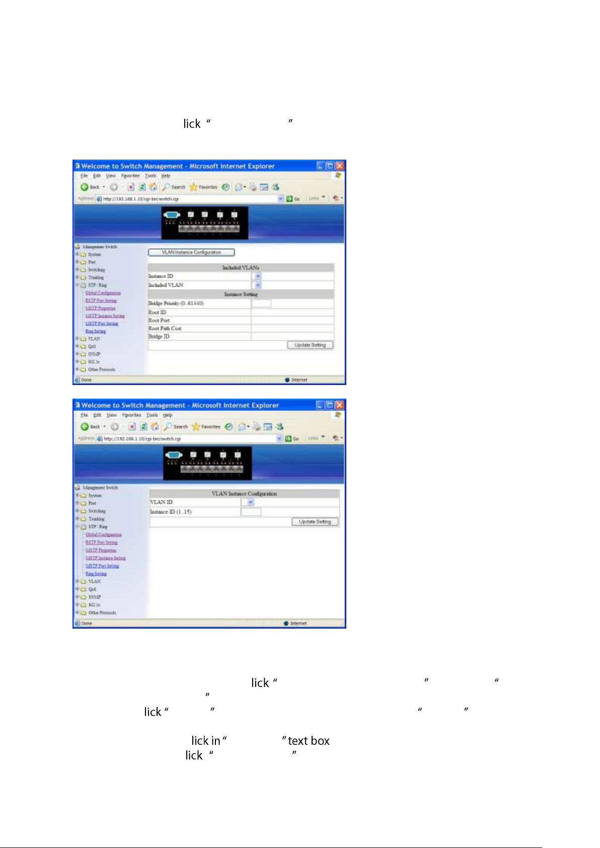
MSTP Instance Setting
VLAN Instance Configuration
1. VLAN Instance Configuration: C VLAN Instance Configuration button. The VLAN
Instance Configuration window appears.
2. VLAN ID: C VLAN ID drop-down menu to choose VLAN from VLAN ID drop-down
list to simultaneously add multiple VLANs for the corresponding instance of a bridge.
3. Instance ID (1..15): C Instance ID to specify the instance ID.
4. Update setting: C Update setting button when you finished VLAN Instance
User Manual Page 52
Page 53
Configuration.
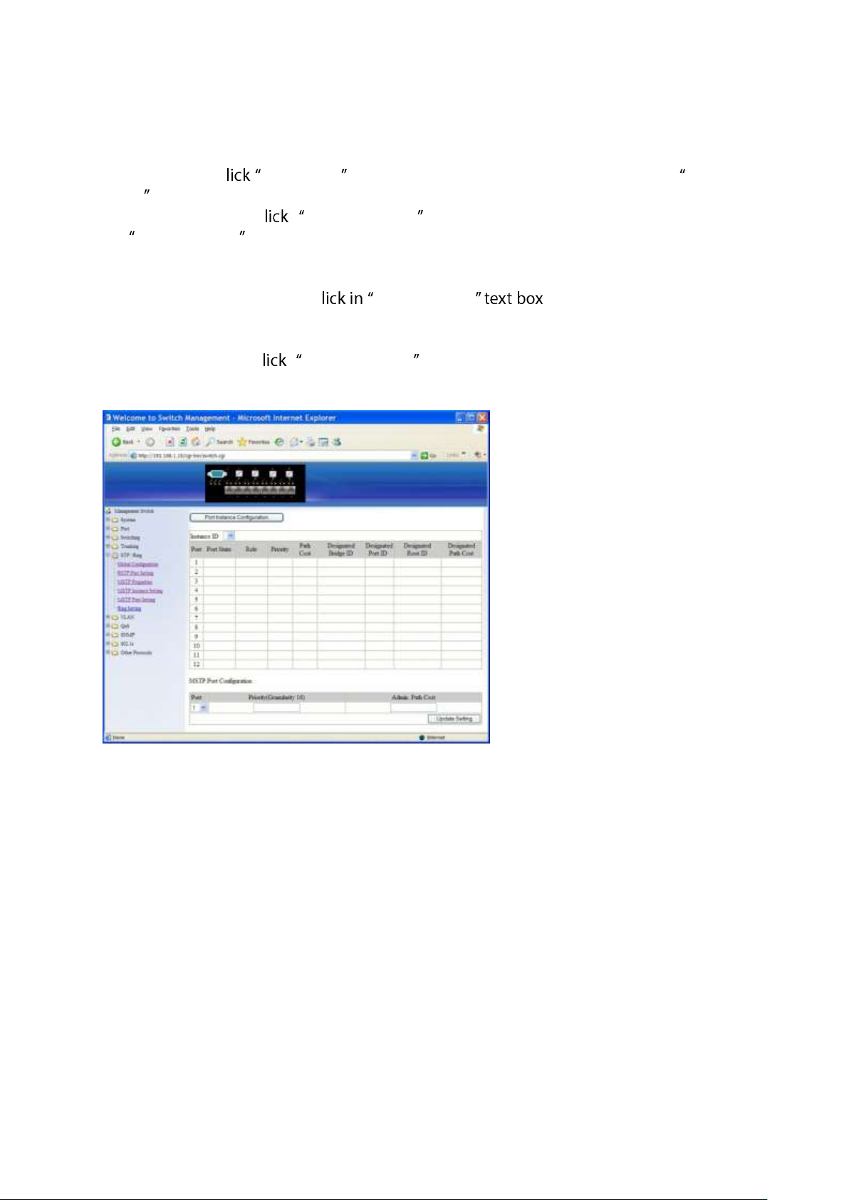
Included VLANs
1. Instance ID: C Instance ID drop-down menu to choose instance ID from Instance
ID drop-down list.
2. Included VLAN: C Included VLAN drop-down menu to choose VLAN from
Included VLAN drop-down list.
Instance Setting
1. Bridge Priority (0..61440): C Bridge Priority to set the bridge priority for
an MST instance to the value specified. The lower the priority of the bridge, the better
the chances are the bridge becoming a root bridge or a designated bridge for the LAN.
2. Update setting: C Update setting button when you finished VLAN Instance
Configuration.
User Manual Page 53
Page 54
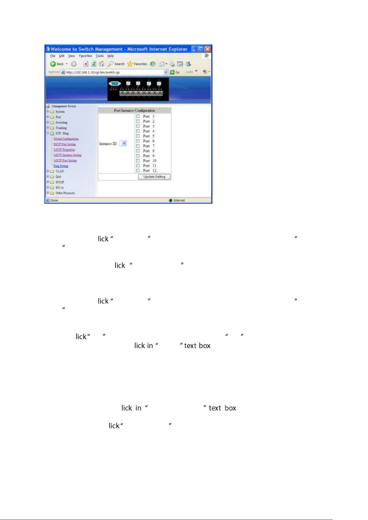
MSTP Port Setting
Port Instance Configuration
1. Instance ID: C Instance ID drop-down menu to choose instance ID from Instance
ID drop-down list.
2. Click Port 1 ~ Port 12 to assign ports to the corresponding instance ID.
3. Update setting: C Update setting button when you finished Port Instance
Configuration.
Instance ID
1. Instance ID: C Instance ID drop-down menu to choose instance ID from Instance
ID drop-down list.
MSTP Port Configuration
1. Port: C Port drop-down menu to choose port from Port drop-down list.
2. Priority(Granularity 16): C Priority to set the port priority for a bridge
group. The Multiple Spanning Tree Protocol uses port priority as a tiebreaker to
determine which port should forward frames for a particular instance on a LAN, or
which port should be the root port for an instance. A lower value implies a better
priority. In the case of the same priority, the interface index will serve as the tiebreaker,
with the lower-numbered interface being preferred over others. The permitted range
is 0-240. The priority values can only be set in increments of 16.
3. Admin. Path Cost: C Admin. Path Cost to set the cost of a path
associated with an interface.
4. Update setting: C Update setting button when you finished MSTP Port Setting.
User Manual Page 54
Page 55
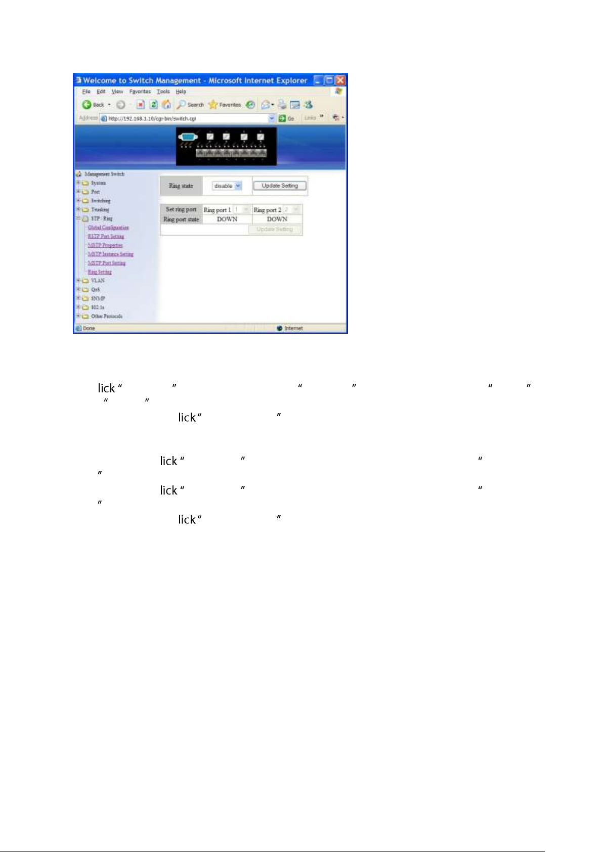
Ring Setting
Ring state
1. C Ring state drop-down menu from Ring state drop-down list to choose Enable
or Disable to enable or disable Ring state.
2. Update setting: C Update setting button when you finished Ring state setting.
Set ring port
1. Ring port 1: C Ring port 1 drop-down menu to choose Ring port 1 from Ring port
1 drop-down list.
2. Ring port 2: C Ring port 2 drop-down menu to choose Ring port 2 from Ring port
2 drop-down list.
3. Update setting: C Update setting button when you finished Set ring port.
User Manual Page 55
Page 56
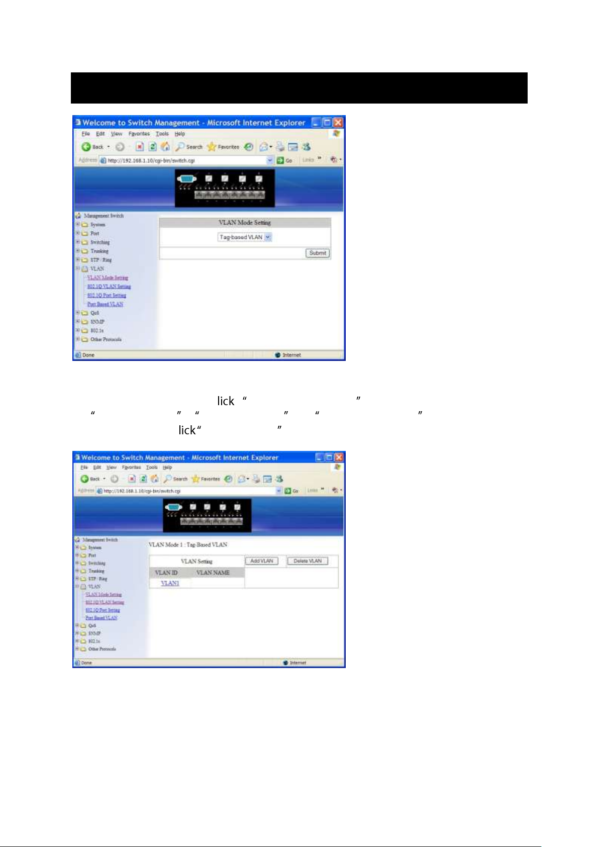
VLAN
VLAN Mode Setting
1. VLAN Mode Setting: C VLAN Mode Setting drop-down menu to Choose
Tag-based VLAN or Port-based VLAN from VLAN Mode Setting drop-down list.
2. Update Setting: C Update Setting button when you finished VLAN Mode Setting.
User Manual Page 56
Page 57
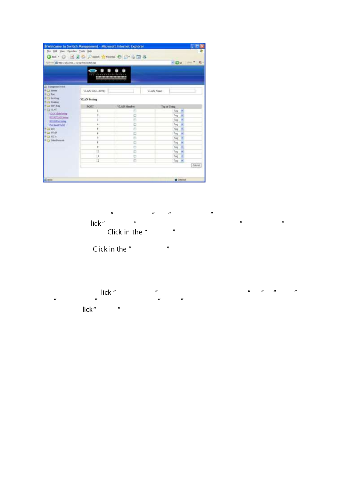
802.1Q VLAN Setting
Add VLAN:
1. VLAN setting: Click VLAN setting. The VLAN Setting window appears.
2. Add VLAN: C Add VLAN button to create a new VLAN from VLAN Setting window.
3. VLAN ID(2-4094): VLAN ID textbox and specify a new VLAN ID number
from 2 ~ 4094.
4. VLAN Name: VLAN Name textbox and type a name for this newly created
VLAN.
Add port to or delete port from VLAN:
1. VLAN Member: Choose the port to be added to or deleted from the VLAN.
2. Tag or Untag: C Tag or Untag drop-down menu to Choose Tag or Untag from
Tag or Untag drop-down list for a Hybrid port.
3. Submit: C Submit button when you finished VLAN setting.
User Manual Page 57
Page 58
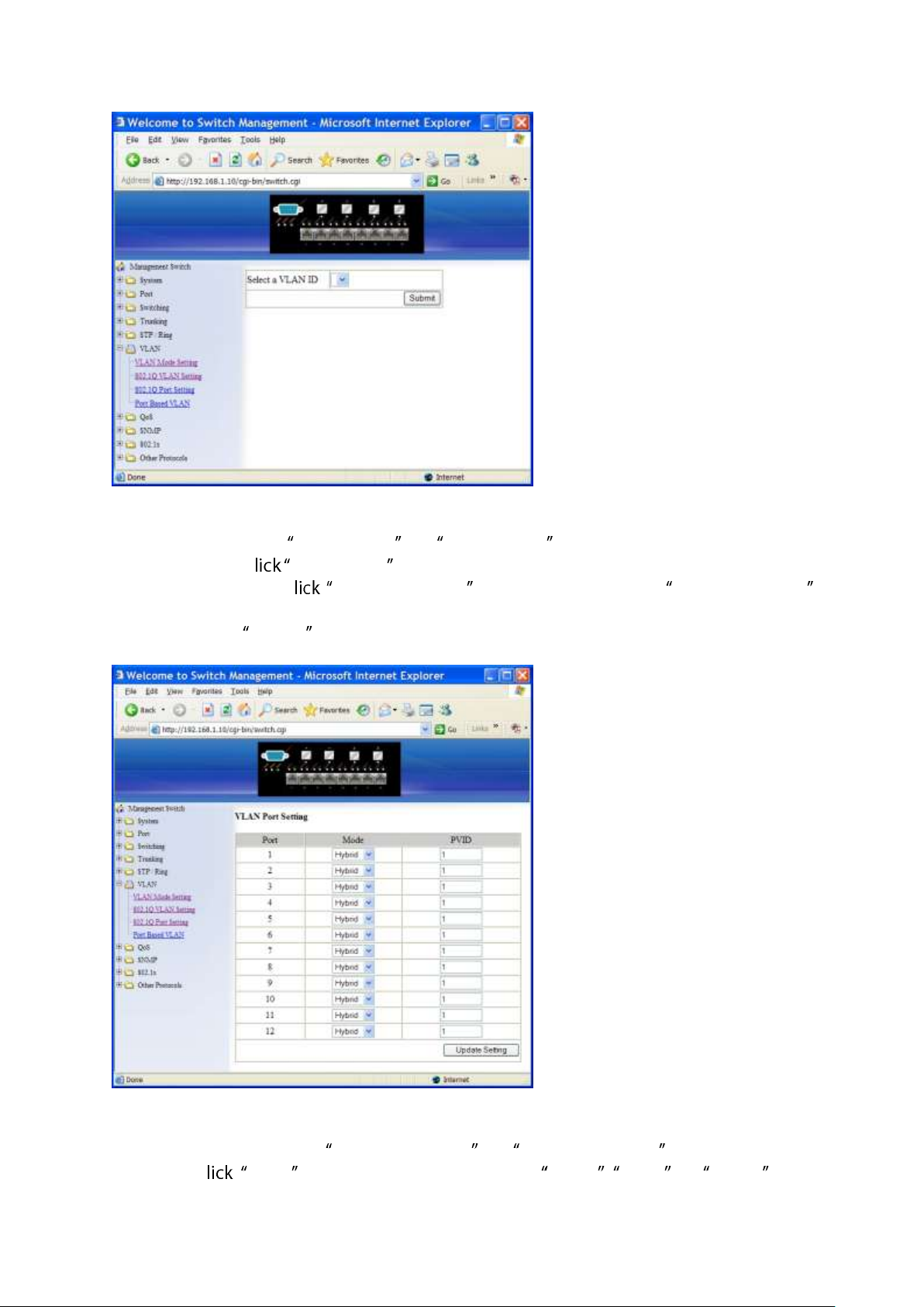
Delete VLAN:
1. VLAN setting: Click VLAN setting. The VLAN Setting window appears.
2. Delete VLAN: C Delete VLAN button.
3. Select a VLAN ID: C Select a VLAN ID drop-down menu from Select a VLAN ID
drop-down list to choose the VLAN to be deleted.
4. Submit: Click Submit button when you finished VLAN setting.
VLAN Port Setting
1. VLAN Port Setting: Click VLAN Port Setting. The VLAN Port Setting window appears.
2. Mode: C Mode drop-down menu to Choose Access, Trunk , or Hybrid from
User Manual Page 58
Page 59
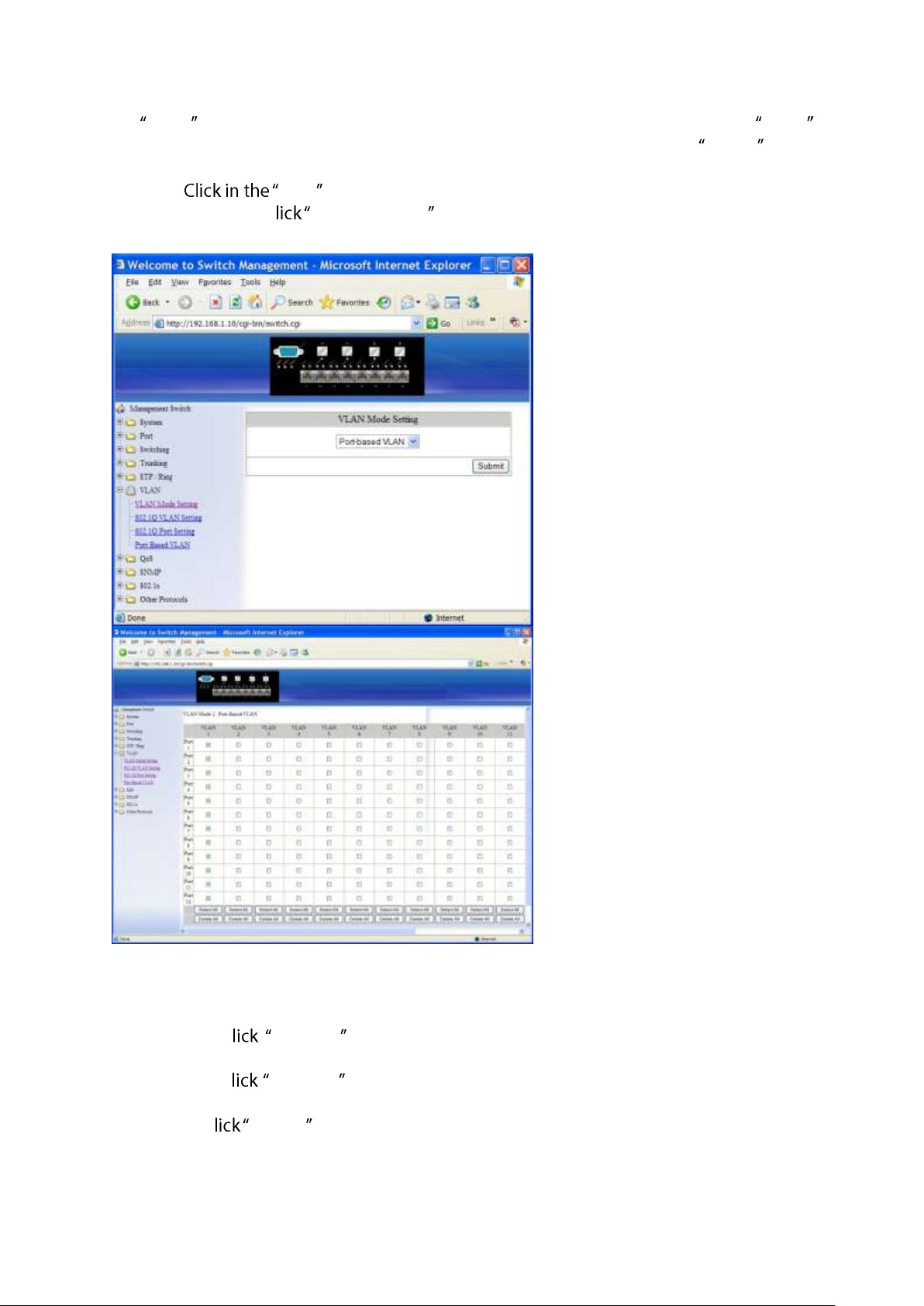
Mode drop-down list for the port. The port will be Tag port if you choose Trunk
Mode for the port. And the port will be Tag or Untag port if you choose Hybrid Mode
for the port.
3. PVID: PVID textbox and specify a new PVID number for the port.
4. Update Setting: C Update Setting button when you finished VLAN Port Setting.
Port Based VLAN
1. VLAN: Choose the port to be added to or deleted from the VLAN.
2. Select all: C select all button to choose Port 1 ~ Port 12 all to be added to the
VLAN.
3. Delete all: C delete all button to choose Port 1 ~ Port 12 all to be deleted from the
VLAN.
4. Submit: C Submit button when you finished Port Based VLAN setting.
User Manual Page 59
Page 60
QoS
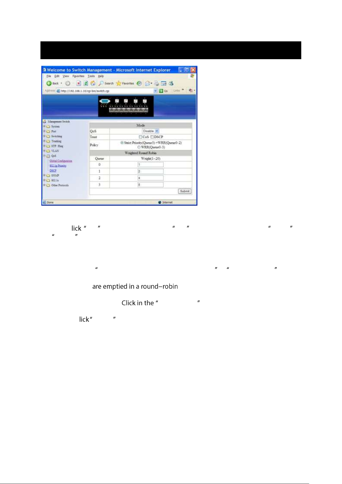
Global Configuration
1. QoS: C QoS drop-down menu from QoS drop-down list to choose Enable or
Disable to enable or disable QoS.
2. Trust: Enable or disable the switch port to trust the CoS (Class of Service) labels of all
traffic received on that port. Enable or disable a routed port to trust the DSCP
(Differentiated Service Code Point) labels of all traffic received on that port.
3. Policy: Choose Strict Priority(Queue3) + WRR(Queue0-2) or WRR(Queue0-3) . A strict
priority queue is always emptied first. The queues that are used in the WRR (Weighted
Round Robin) fashion, and you can configure the weight
for each queue.
4. Weighted Round Robin: Weight(1~55) textbox and specify a new number
from 1 ~ 55 for Queue 0 ~ 3.
5. Submit: C Submit button when you finished Global Configuration.
User Manual Page 60
Page 61
802.1p Priority
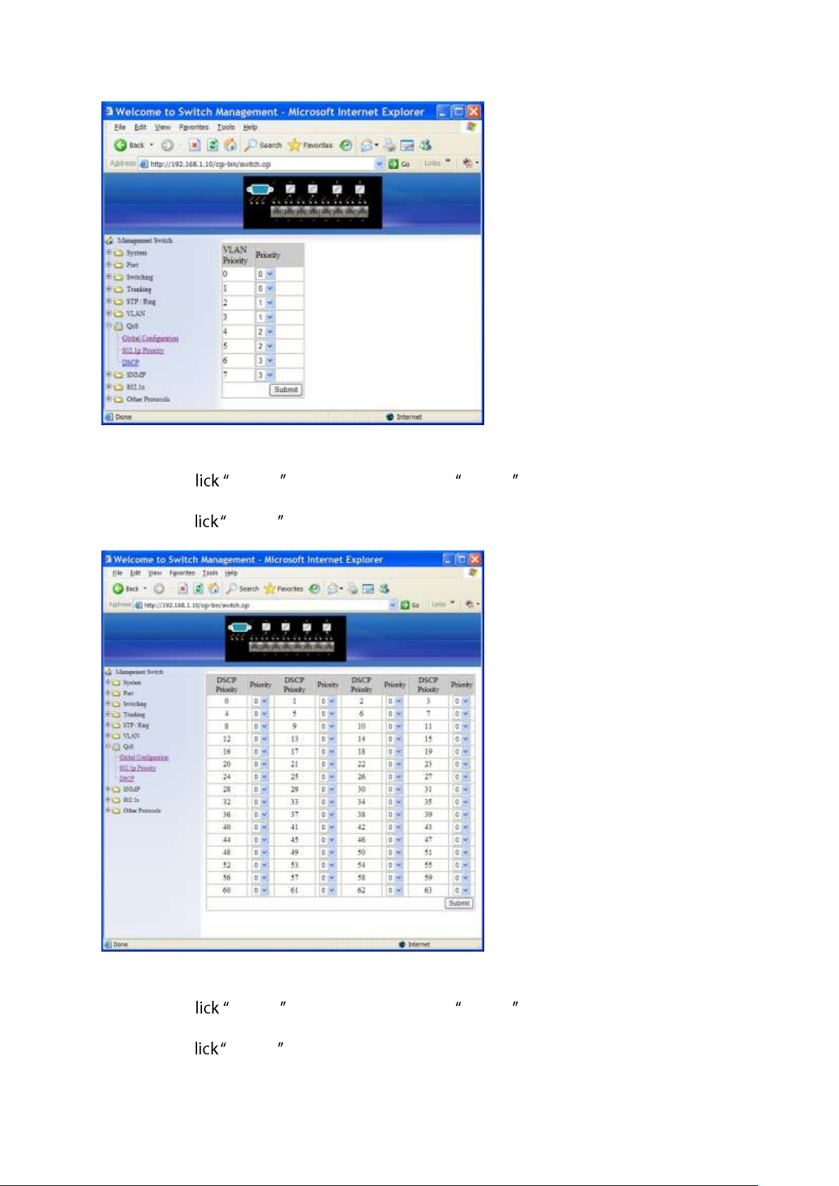
1. Priority: C Priority drop-down menu from Priority drop-down list to choose 0 ~ 3
for VLAN Priority 0 ~ 7.
2. Submit: C Submit button when you finished 802.1p priority.
DSCP
1. Priority: C Priority drop-down menu from Priority drop-down list to choose 0 ~ 3
for DSCP Priority 0 ~ 63.
2. Submit: C Submit button when you finished DSCP.
User Manual Page 61
Page 62
SNMP
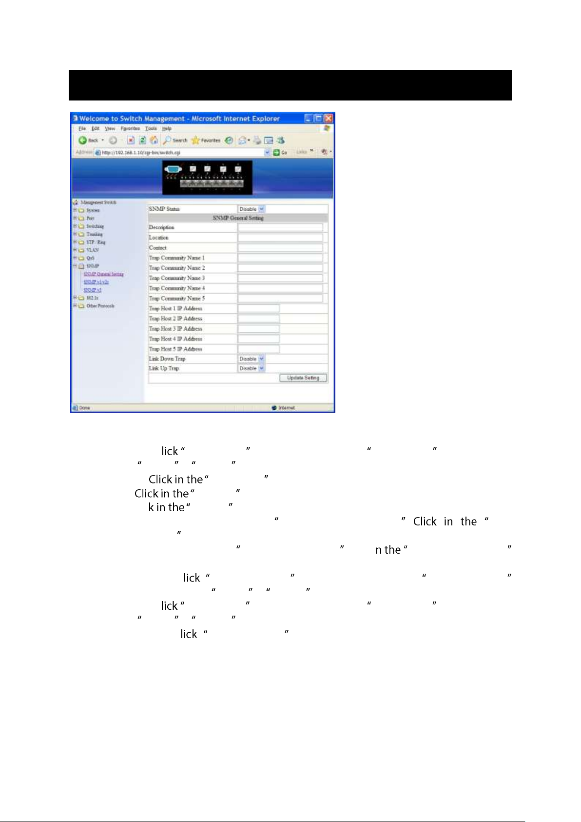
SNMP General Setting
1. SNMP Status: C SNMP Status drop-down menu from SNMP Status drop-down list
to choose Enable or Disable to enable or disable SNMP.
2. Description: Description textbox and specify a new description for SNMP.
3. Location: Location textbox and specify a new location for SNMP.
4. Contact: Clic Contact textbox and specify a new contact for SNMP.
5. Trap Community Name: For each Trap Community Name, Trap
Community Name textbox and specify a trap community name.
6. Trap Host IP Address: For each Trap Host IP Address, Click i Trap Host IP Address
textbox and specify a trap host IP address.
7. Link Down Trap: C Link Down Trap drop-down menu from Link Down Trap
drop-down list to choose Enable or Disable to enable or disable link down trap.
8. Link Up Trap: C Link Up Trap drop-down menu from Link Up Trap drop-down list
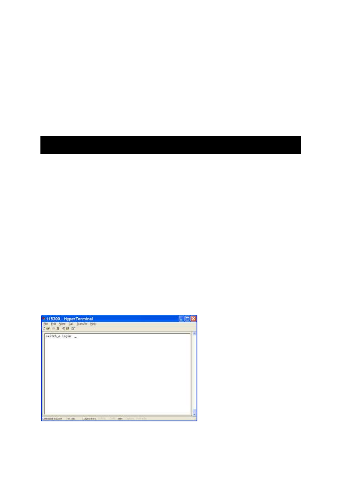
to choose Enable or Disable to enable or disable link up trap.
9. Update Setting: C Update Setting button when you finished SNMP General
Setting.
User Manual Page 62
Page 63
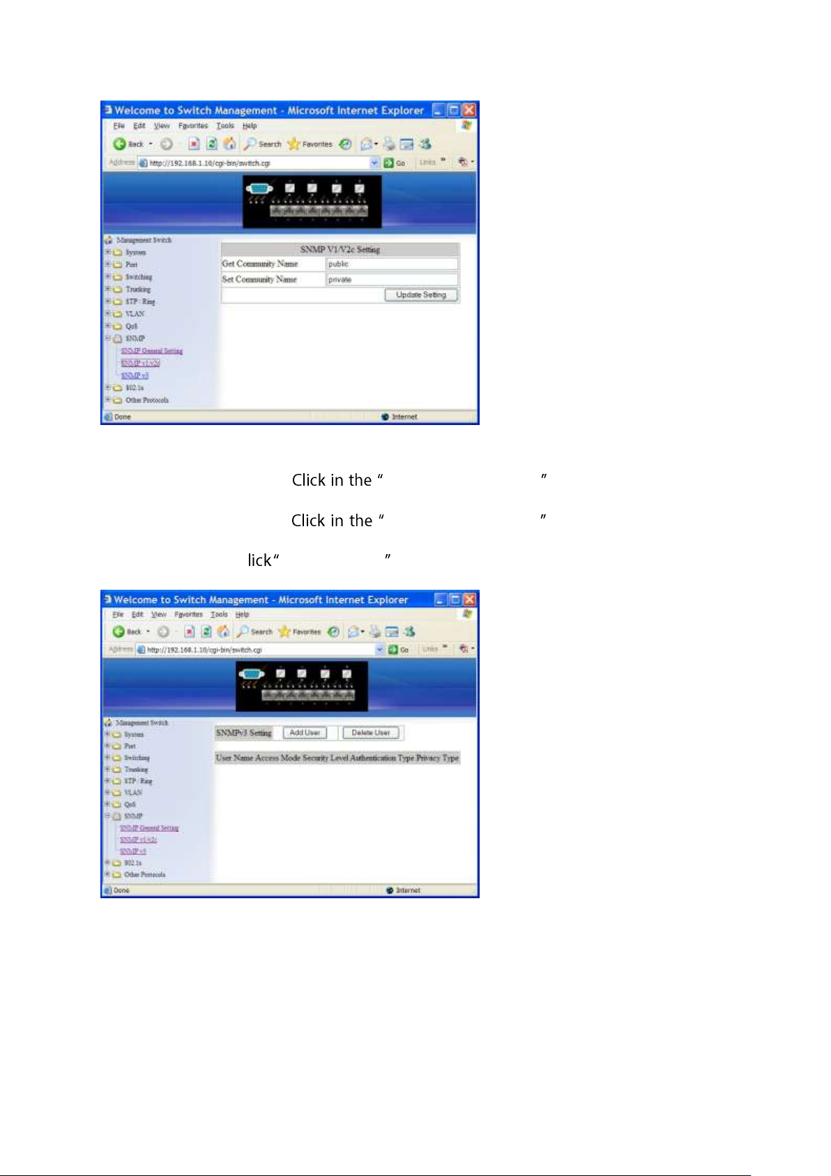
SNMP v1/v2c
1. Get Community Name: Get Community Name textbox and specify a get
community name.
2. Set Community Name: Set Community Name textbox and specify a set
community name.
3. Update Setting: C Update Setting button when you finished SNMP V1/V2c Setting.
User Manual Page 63
Page 64
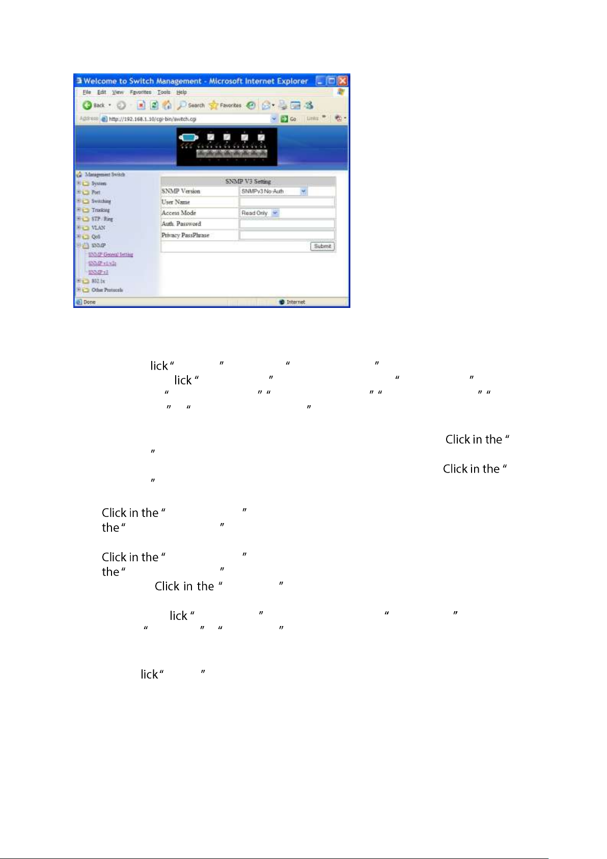
SNMP v3
Add User:
1. Add User: C Add User button. The SNMP V3 Setting window appears.
2. SNMP Version: C SNMP Version drop-down menu from SNMP Version drop-down
list to choose SNMPv3 No-Auth, SNMPv3 Auth-MD5 , SNMPv3 Auth-SHA, SNMPv3
Priv Auth-MD5, or SNMPv3 Priv Auth-SHA.
SNMPv3 No-Auth: Add a user using SNMP v3 without authentication.
SNMPv3 Auth-MD5: Add a user using SNMP v3 with authentication. Auth.
Password textbox and specify an authentication password.
SNMPv3 Auth-SHA: Add a user using SNMP v3 with authentication. Auth.
Password textbox and specify an authentication password.
SNMPv3 Priv Auth-MD5: Add a user using SNMP v3 with authentication and privacy.
Auth. Password textbox and specify an authentication password. Click in
Privacy PassPhrase textbox and specify a privacy pass phrase.
SNMPv3 Priv Auth-SHA: Add a user using SNMP v3 with authentication and privacy.
Auth. Password textbox and specify an authentication password. Click in
Privacy PassPhrase textbox and specify a privacy pass phrase.
3. User Name: User Name textbox and specify a user name for user using
SNMP v3.
4. Access Mode: C Access Mode drop-down menu from Access Mode drop-down list
to choose Read Only or Read/Write.
Read Only: Add a user using SNMP v3 with read-only access mode.
Read/Write: Add an user using SNMP v3 with read-write access mode
5. Submit: C Submit button when you finished SNMP V3 Setting.
User Manual Page 64
Page 65
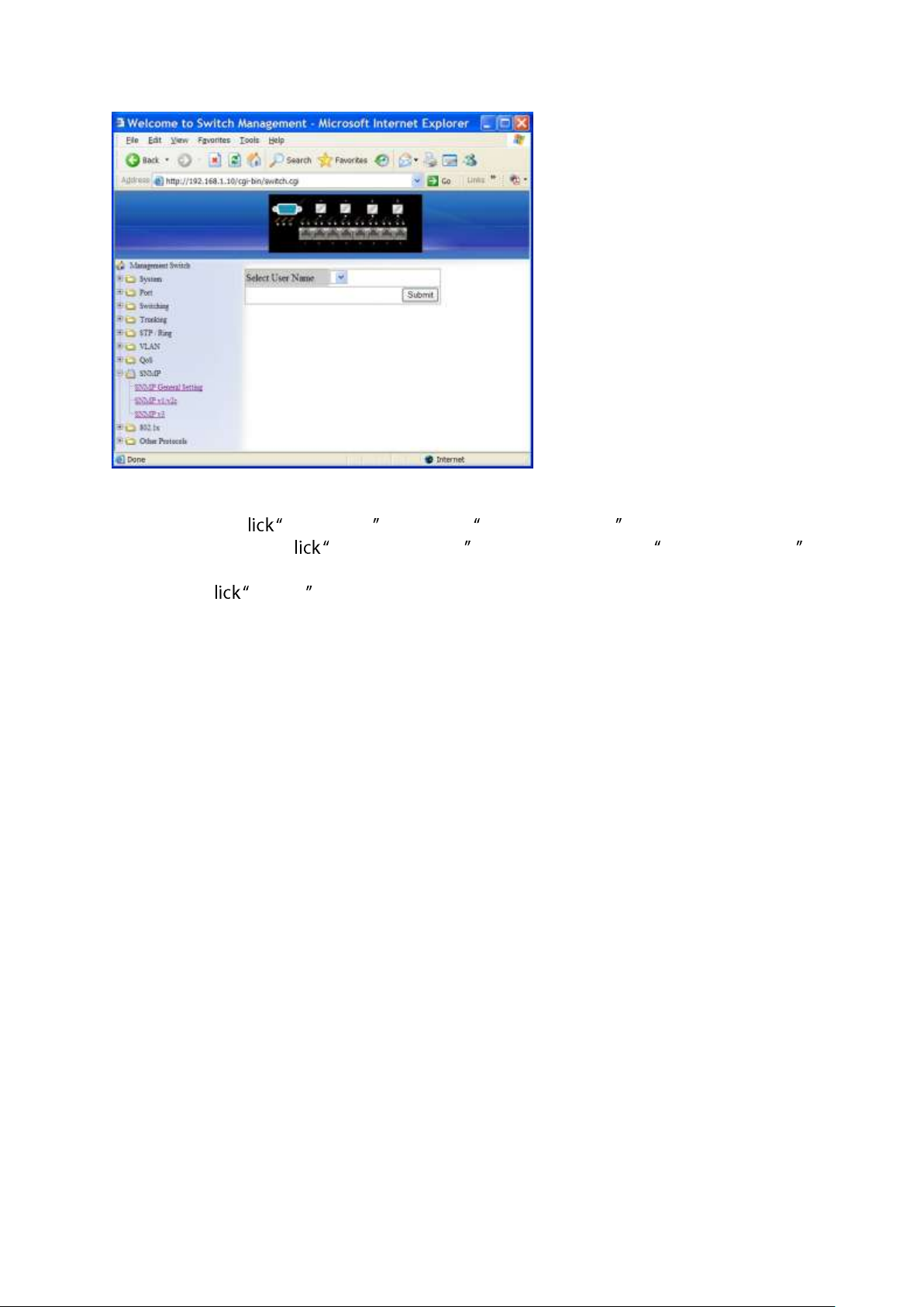
Delete User:
1. Delete User: C Delete User button. The Select User Name window appears.
2. Select User Name: C Select User Name drop-down menu from Select User Name
drop-down list to choose the user to be deleted from using SNMP v3.
3. Submit: C Submit button when you finished user deletion.
User Manual Page 65
Page 66
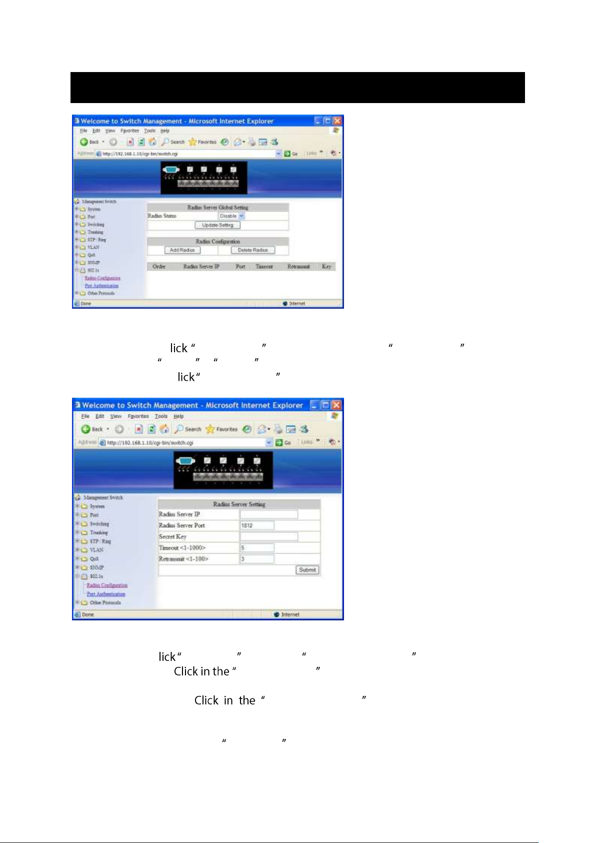
802.1x
Radius Configuration
1. Radius Status: C Radius Status drop-down menu from Radius Status drop-down
list to choose Enable or Disable to globally enable or disable authentication.
2. Update Setting: C Update Setting button when you finished Radius Status Setting.
Add Radius:
1. Add Radius: C Add Radius button. The Radius Server Setting window appears.
2. Radius Server IP: Radius Server IP textbox and specify the IP address of the
remote radius server host.
3. Radius Server Port: Radius Server Port textbox and specify the UDP
destination port for authentication requests. The host is not used for authentication if
set to 0.
4. Secret Key: Click in the Secret Key textbox and specify the authentication and
encryption key for all radius communications between the Switch and radius server.
User Manual Page 66
Page 67
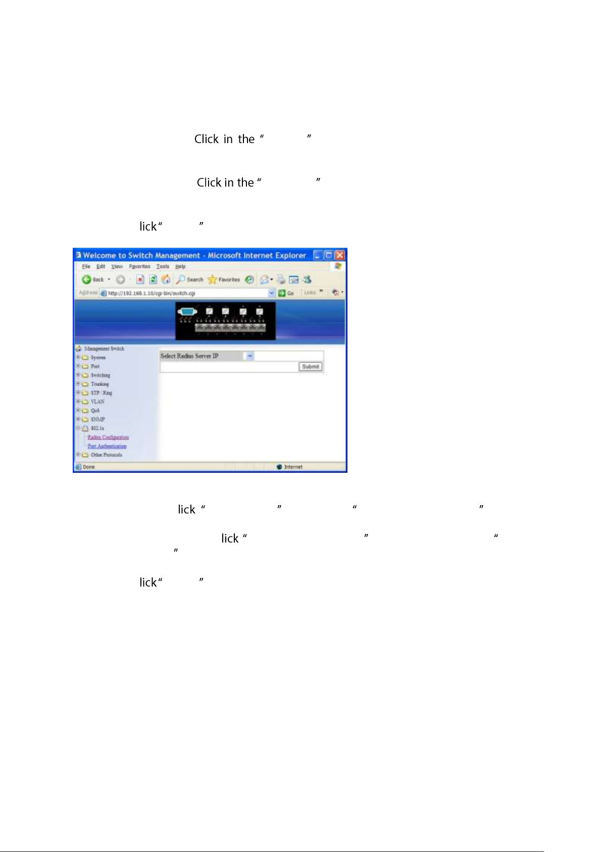
This key must match the encryption used on the radius daemon. All leading spaces are
ignored, but spaces within and at the end of the key are used. If spaces are used in the
key, do not enclose the key in quotation marks unless the quotation marks themselves
are part of the key.
5. Timeout <1-1000>: Timeout textbox and specify the time interval (in
seconds) that the Switch waits for the radius server to reply before retransmitting.
Enter a value in the range 1 to 1000.
6. Retransmit <1-100>: Retransmit textbox and specify the number of times
a radius request is resent to a server if that server is not responding or responding
slowly. Enter a value in the range 1 to 100.
7. Submit: C Submit button when you finished Radius Server Setting.
Delete Radius:
1. Delete Radius: C Delete Radius button. The Select Radius Server IP window
appears.
2. Select Radius Server IP: C Select Radius Server IP drop-down menu from Select
Radius Server IP drop-down list to choose the IP address of the remote radius server
host to be deleted.
3. Submit: C Submit button when you finished radius server deletion.
User Manual Page 67
Page 68
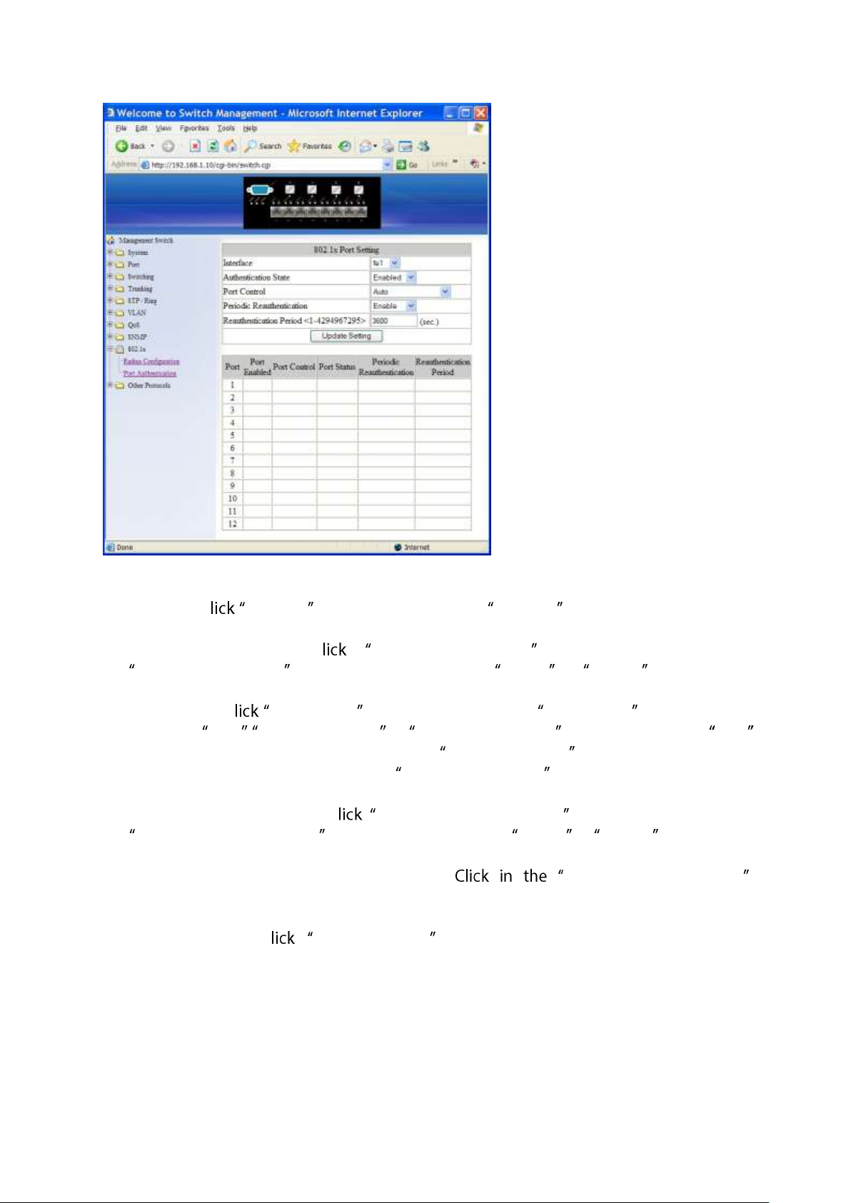
Port Authentication
1. Interface: C Interface drop-down menu from Interface drop-down list to choose
the port to be set port-based authentication.
2. Authentication State: C Authentication State drop-down menu from
Authentication State drop-down list to choose Enable or Disable to enable or
disable authentication state.
3. Port Control: C Port Control drop-down menu from Port Control drop-down list
to choose Auto, Force Authorized, or Force Unauthorized to force a port state. Auto
specifies to enable authentication on port. Force Authorized specifies to force a port
to always be in an authorized state. Force Unauthorized specifies to force a port to
always be in an unauthorized state.
4. Periodic Reauthentication: C Periodic Reauthentication drop-down menu from
Periodic Reauthentication drop-down list to choose Enable or Disable to enable or
disable periodic reauthentication.
5. Reauthentication Period <1-4294967295>: Reauthentication Period
textbox and specify the seconds between reauthorization attempts. The default time is
3600 seconds.
6. Update Setting: C Update Setting button when you finished port-based
authentication setting.
User Manual Page 68
Page 69
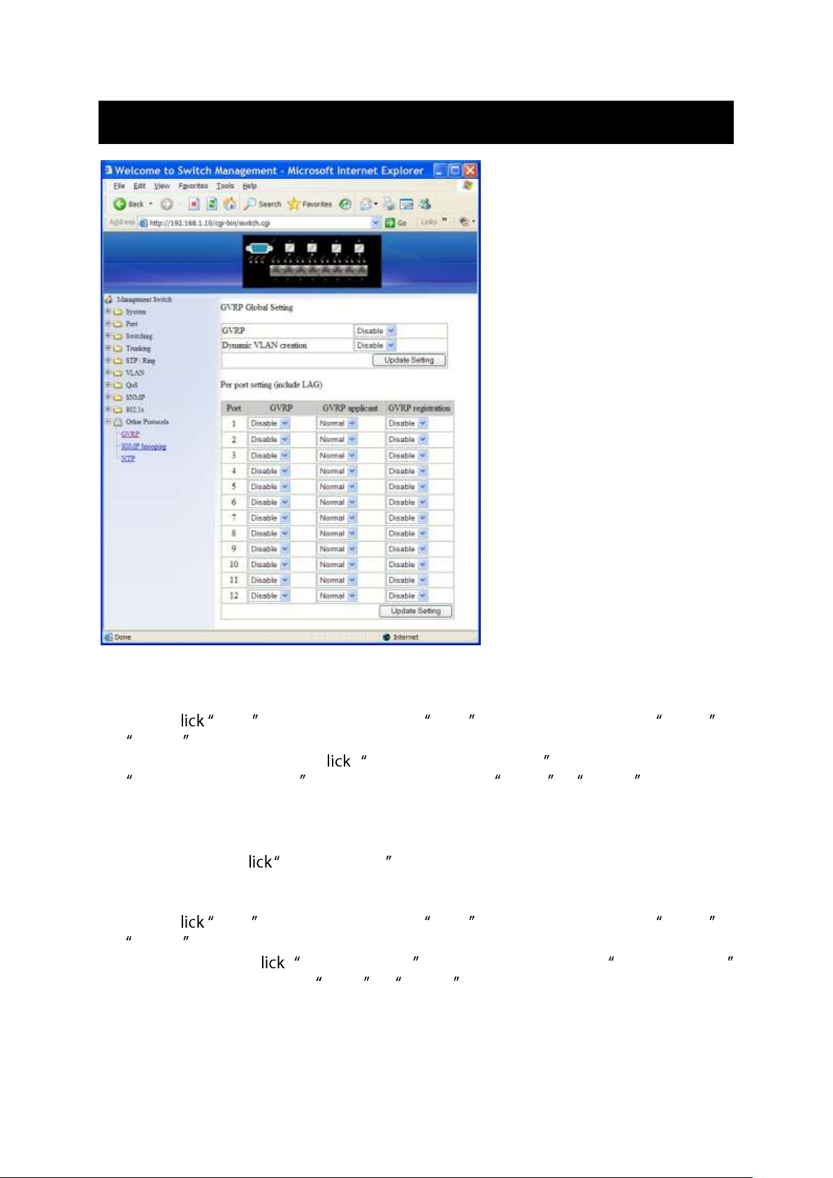
Other Protocols
GVRP
GVRP Global Setting:
1. GVRP: C GVRP drop-down menu from GVRP drop-down list to choose Enable or
Disable to enable or disable GVRP (GARP VLAN Registration Protocol).
2. Dynamic VLAN creation: C Dynamic VLAN creation drop-down menu from
Dynamic VLAN creation drop-down list to choose Enable or Disable to enable or
disable Dynamic VLAN creation. GARP (Generic Attribute Registration Protocol)
provides IEEE802.1Q compliant VLAN pruning and dynamic VLAN creation on
IEEE802.1Q trunk ports.
3. Update Setting: C Update Setting button when you finished GVRP Global Setting.
Per port setting (include LAG):
1. GVRP: C GVRP drop-down menu from GVRP drop-down list to choose Enable or
Disable to enable or disable GVRP for the port.
2. GVRP applicant: C GVRP applicant drop-down menu from GVRP applicant
drop-down list to choose Active or Normal to the port. Ports in the GVRP active
applicant state send GVRP VLAN declarations when they are in the STP (Spanning Tree
Protocol) blocking state, which prevents the STP bridge protocol data units (BPDUs)
from being pruned from the other port. Ports in the GVRP normal applicant state do
not declare GVRP VLANs when in the STP blocking state.
User Manual Page 69
Page 70
3. GVRP registration: C GVRP registration drop-down menu from GVRP registration
drop-down list to choose Enable or Disable to enable or disable GVRP registration to
the port. Configuring an IEEE802.1Q trunk port in registration mode allows dynamic
creation (if dynamic VLAN creation is enabled), registration, and deregistration of
VLANs on the trunk port.
4. Update Setting: C Update Setting button when you finished Per port setting.
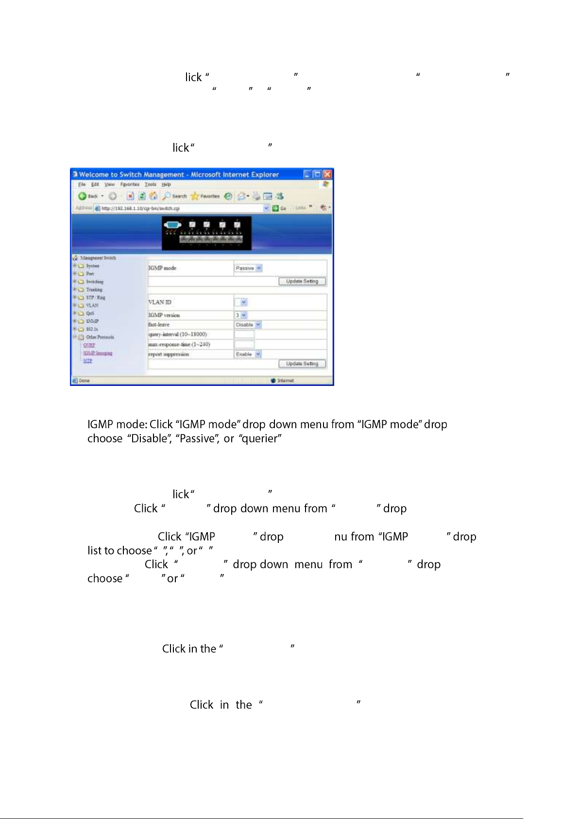
IGMP Snooping
1. - -down list to
for the switch. Disable: Disable IGMP on the
switch. Passive: The switch with only multicast-data-forwarding capability. Querier: The
switch acts as the querier for the network. There is only one querier on a network at
any time.
2. Update Setting: C Update Setting button when you finished IGMP mode settings.
3. VLAN ID: VLAN ID - VLAN ID -down list to choose
the VLAN under configuration for the switch.
4. IGMP version: version -down me version -down
1 2 3 for the switch.
5. Fast-leave: fast-leave - fast-leave -down list to
Enable Disable for the switch. Enable this function will allow members of a
multicast group to leave the group immediately when an IGMP Leave Report Packet is
received by the Switch.
IGMP querier:
1. Query-interval: query-interval textbox and specify a new number from 1 ~
18000. The query-interval field is used to set the time (in seconds) between
transmitting IGMP queries. Entries between 1 and 18000 seconds are allowed. Default
= 125.
2. Max-response-time: max-response-time textbox and specify a new
number from 1 ~ 124. This determines the maximum amount of time in seconds
allowed before sending an IGMP response report. The max-response-time field allows
User Manual Page 70
Page 71
an entry between 1 and 124 (seconds). Default = 10.
IGMP passive snooping:
1. Report suppression: report suppression - report
suppression - Enable Disable for the switch. Use this
command to enable report suppression for IGMP version 1 and version 2. Report
suppression does not apply to IGMP version 3, and is turned off by default for IGMP
version 1 and IGMP version 2 reports. The switch uses IGMP report suppression to
forward only one IGMP report per multicast router query to multicast devices. When
IGMP router suppression is enabled, the switch sends the first IGMP report from all
hosts for a group to all the multicast routers. The switch does not send the remaining
IGMP reports for the group to the multicast routers. This feature prevents duplicate
reports from being sent to the multicast devices.
2. Update Setting: C Update Setting button when you finished IGMP Snooping.
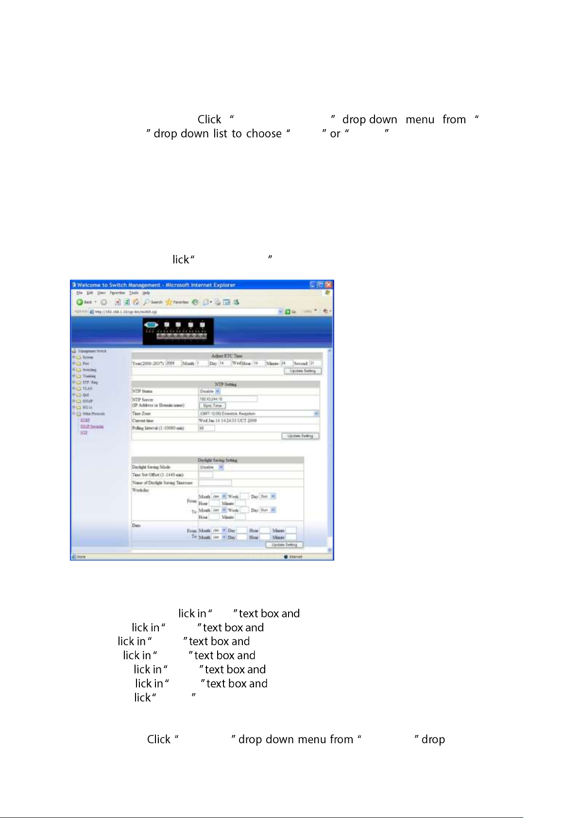
NTP
Adjust RTC Time: Adjust system time for this Switch.
1. Year(2000-2099): C Year specify year 2000 to 2099.
2. Month: C Month specify 1 to 12.
3. Day: C Month specify 1 to 31.
4. Hour: C Month specify 0 to 23.
5. Minute: C Month specify 0 to 59.
6. Second: C Month specify 0 to 59.
7. Submit: C Submit button when you finished Adjust RTC Time.
NTP Setting:
1. NTP Status: NTP Status - NTP Status -down list to
User Manual Page 71
Page 72

Enable Disable to enable or disable NTP for the Switch.
2. NTP Server (IP Address or Domain name): NTP Server textbox and specify
the IP address or Domain name of NTP server.
3. Sync Time: C Sync Time button to synchronize time with NTP server.
4. Time Zone: Time Zone - Time Zone -down list to set
time zone.
5. Polling Interval (1-10080 min): Polling Interval textbox and specify the
polling interval.
6. Update Setting: C Update Setting button when you finished NTP Setting.
Daylight Saving Setting:
1. Daylight Saving Mode: Click "Daylight Saving Mode" drop-down menu from "Daylight
Saving Mode" drop-down list to choose "Disable", "Weekday", or "Date" to choose
disable, weekday, or date daylight saving for the Switch.
2. Time Set Offset (1-1440 min): Click in the "Time Set Offset" textbox and specify the
offset time of daylight saving. For example enter 60 for one hour offset.
3. Name of Daylight Saving Timezone: Click in the " Name of Daylight Saving Timezone"
textbox and specify the daylight saving timezone. This can be any given name in
14-character alpha-numerical. Enter the Daylight-Saving time zone using the following
example:
EDT - East Daylight Saving Time Zone.
CDT - Central Daylight-Saving Time Zone.
MDT - Mountain Daylight-Saving Time Zone.
PDT - Pacific Daylight-Saving Time Zone.
ADT - Alaska Daylight-Saving Time Zone.
4. Weekday: Click in the textboxes and specify the daylight saving period.
Month: Click "Month" drop-down menu from "Month" drop-down list to choose
from January to December.
Week: <1-5> Specifies weekdays from Monday to Friday.
Day: Click "Day" drop-down menu from "Day" drop-down list to choose from
Sunday to Saturday.
Hour: <0-23> Specifies from 0 to 23.
Minute: <0-59> Specifies from 0 to 59.
5. Date: Click in the textboxes and specify the daylight saving period.
Month: Click "Month" drop-down menu from "Month" drop-down list to choose
from January to December.
Day: <1-31> Specifies from 1 to 31.
Hour: <0-23> Specifies from 0 to 23.
Minute: <0-59> Specifies from 0 to 59.
6. Update Setting: Click "Update Setting" button when you finished Daylight Saving
Setting.
<Note> T W , Hour , Minute , Day s would not accept the
alphabetic characters (Like Jan, Feb, sun, mon). They only accept the two digit
numbers (0 through 9).
User Manual Page 72
Page 73
Command Line Console Management
The switch provides a command line console interface for configuration purposes. The
switch can be configured either locally through its RS-232 port or remotely via a Telnet
session. For the later, you must specify an IP address for the switch first.
This chapter describes how to configure the switch using its console by Commend Line.
Administration Console
Connect the DB9 straight cable to the RS-232 serial port of the device to the RS-232 serial
port of the terminal or computer running the terminal emulation application.
Direct access to the administration console is achieved by directly connecting a terminal
or a PC equipped with a terminal-emulation program (such as HyperTerminal) to the
switch console port.
When using the management method, configure the terminal-emulation program to use
the following parameters (you can change these settings after login):
[Default parameters]
115,200bps
8 data bits
No parity
1 stop bit
Exec Mode (View Mode)
Logon to Exec Mode (View Mode)
User Manual Page 73
Page 74
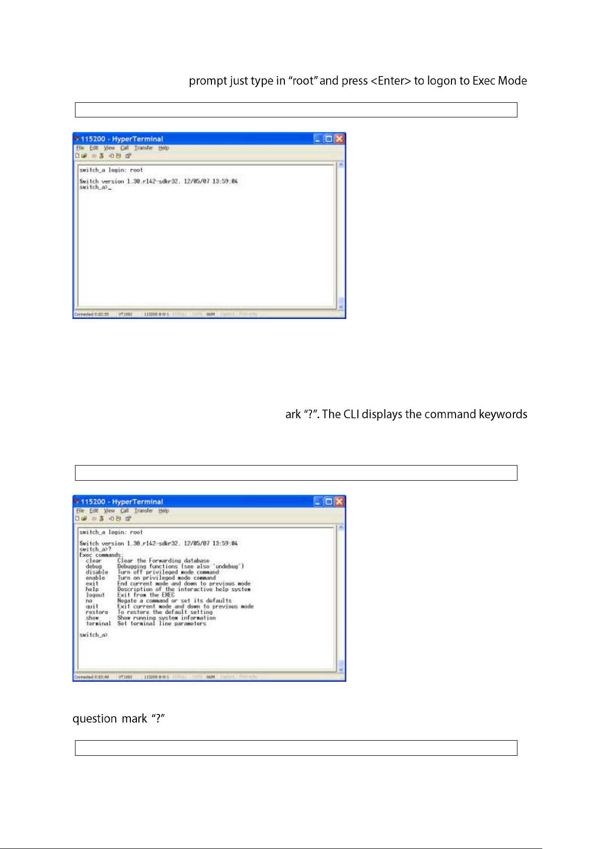
At the switch_a login:
switch_a login: root
switch_a>?
switch_a>show ?
(or View Mode).
Basic commands
Exec Mode (or View Mode) is the base mode from where users can perform basic
commands like:
clear, debug, disable, enable, exit, help, logout, no, quit, show, terminal
The CLI contains a text-based help facility. Access this help by typing in the full or partial
command string then typing a question m
or parameters along with a short description.
At the switch_a> prompt just press <?> to list the above basic commands.
At the switch_a> prompt just type in the full or partial command string then typing a
to display the command keywords or parameters along with a short
description.
User Manual Page 74
Page 75
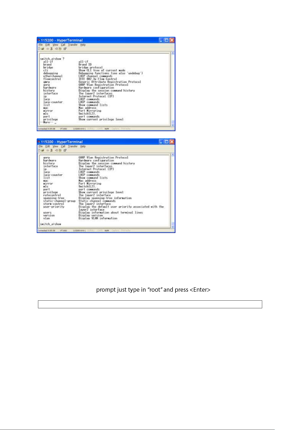
switch_a login: root
Login timed out
The login session to Exec Mode (or View Mode) has timed out due to an extended period
of inactivity (60 seconds) to indicate authentication attempt timed out. And the switch_a
login: prompt will show on the screen.
Logon back to Exec Mode (View Mode)
At the switch_a login: to logon back to Exec
Mode (or View Mode).
User Manual Page 75
Page 76
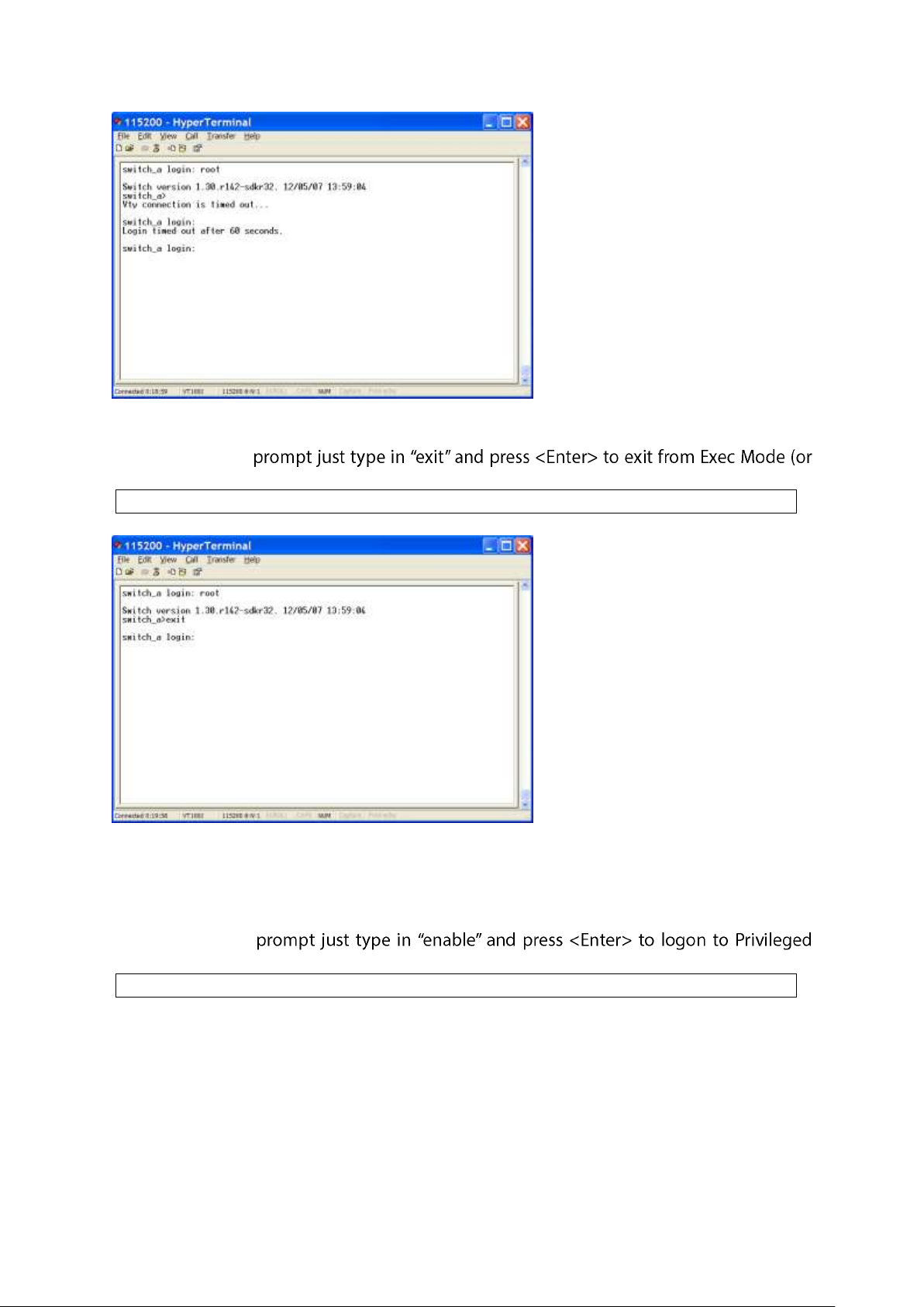
switch_a>exit
switch_a>enable
Exit from Exec Mode (View Mode)
At the switch_a>
View Mode).
Privileged Exec Mode (Enable Mode)
Logon to Privileged Exec Mode (Enable Mode)
At the switch_a>
Exec Mode (or Enable Mode). And the switch_a# prompt will show on the screen.
User Manual Page 76
Page 77
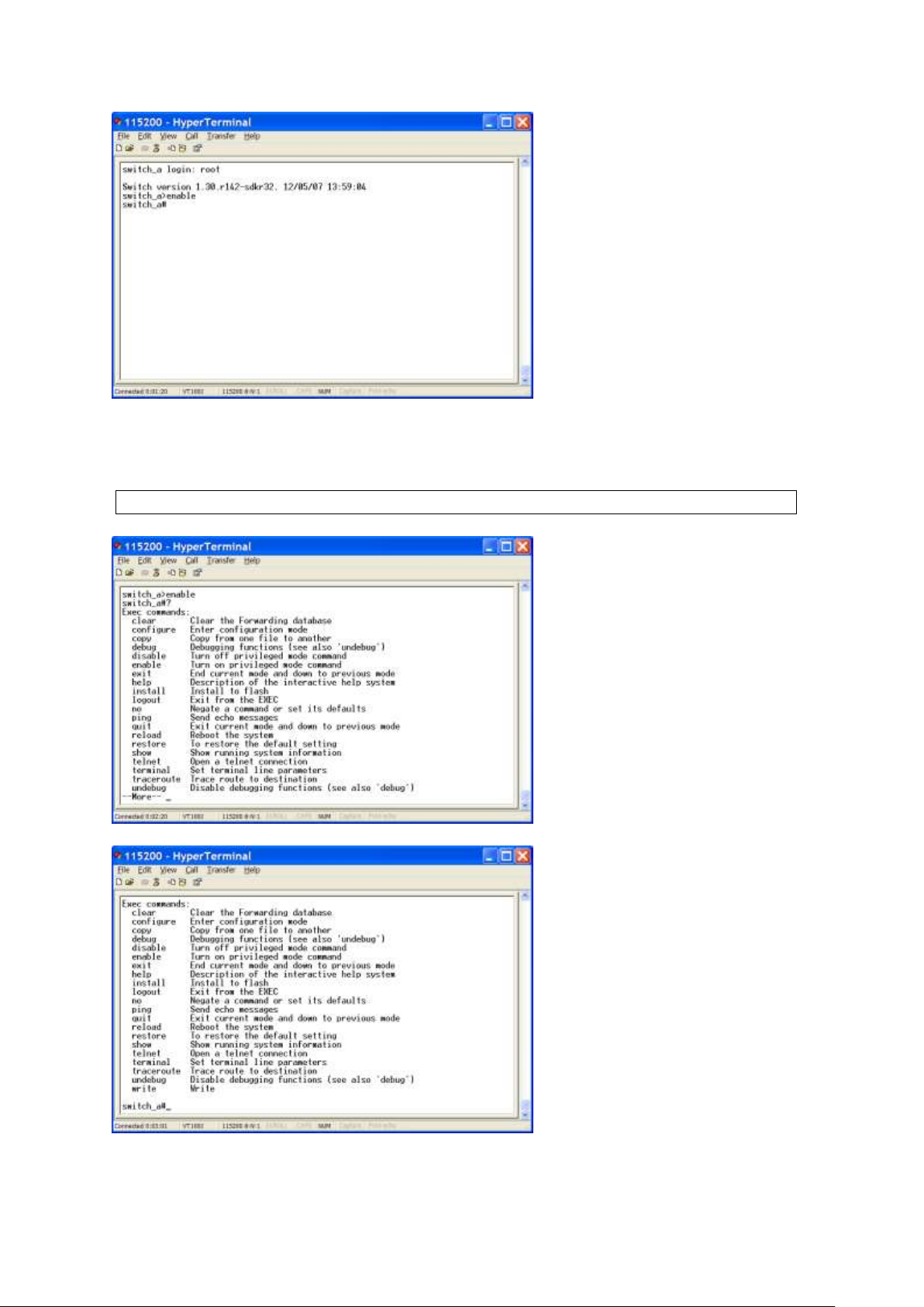
switch_a#?
Commands
Privileged Exec Mode (or Enable Mode) allows users to run commands as following.
At the switch_a# prompt just press <?> to list the commands.
At the switch_a# prompt just type in the full or partial command string then typing a
User Manual Page 77
Page 78
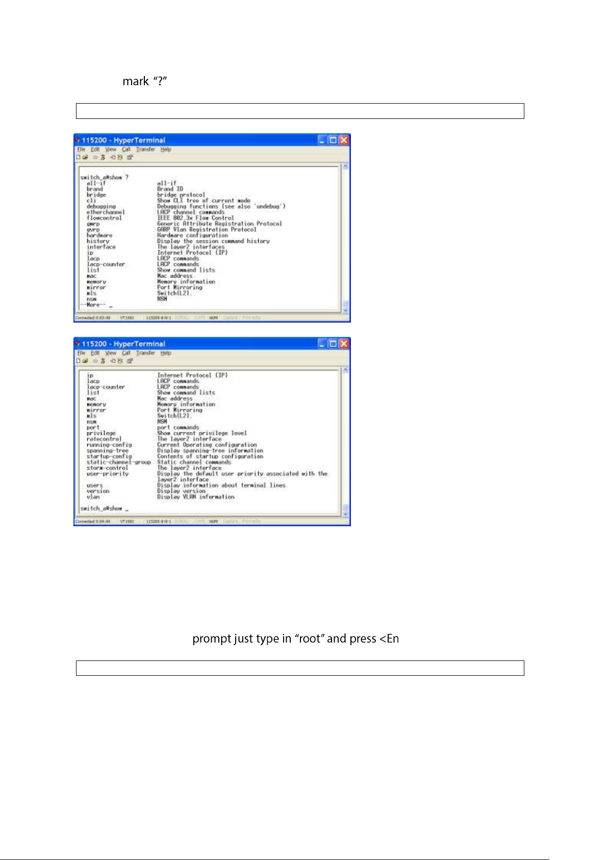
question to display the command keywords or parameters along with a short
switch_a#show ?
switch_a login: root
description.
Login timed out
The login session to Privileged Exec Mode (or Enable Mode) has timed out due to an
extended period of inactivity (60 seconds) to indicate authentication attempt timed out.
And the switch_a login: prompt will show on the screen.
Logon back to Exec Mode (View Mode)
At the switch_a login: ter> to logon back to Exec
Mode (or View Mode).
User Manual Page 78
Page 79
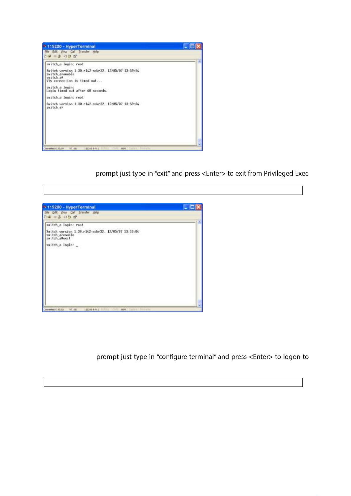
switch_a#exit
switch_a#configure terminal
Exit from Privileged Exec Mode (or Enable Mode)
At the switch_a#
Mode (or Enable Mode).
Configure Mode (Configure Terminal Mode)
Logon to Configure Mode (Configure Terminal Mode)
At the switch_a#
Configure Mode (or Configure Terminal Mode). And the switch_a(config)# prompt will
show on the screen.
User Manual Page 79
Page 80
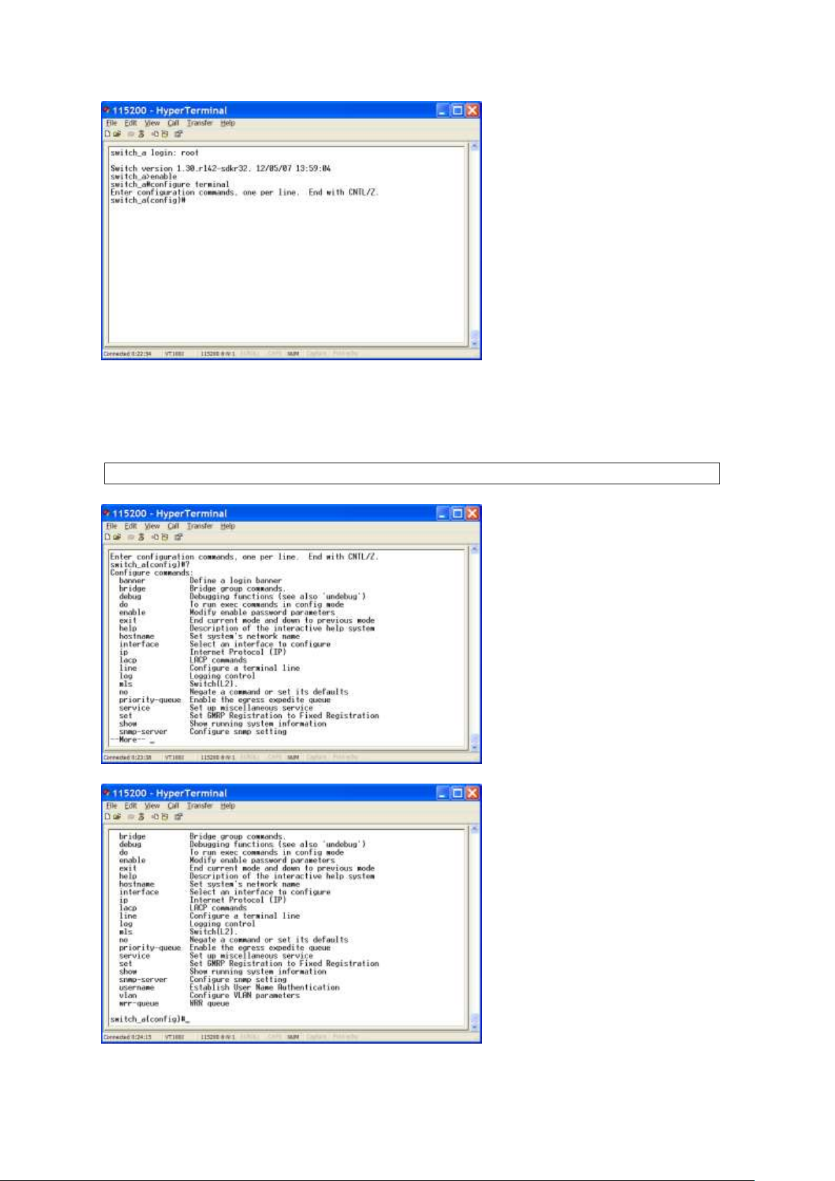
switch_a(config)#?
Commands
Configure Mode (or Configure Terminal Mode) serves as a gateway into the modes as
following.
At the switch_a(config)# prompt just press <?> to list the commands.
User Manual Page 80
Page 81
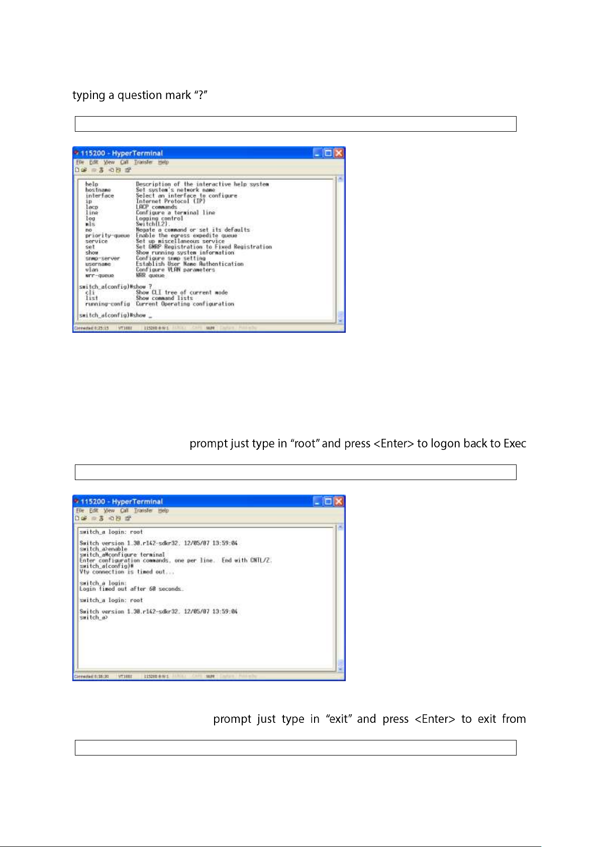
At the switch_a(config)# prompt just type in the full or partial command string then
switch_a(config)#show ?
switch_a login: root
switch_a(config)#exit
to display the command keywords or parameters along with a
short description.
Login timed out
The login session to Configure Mode (or Configure Terminal Mode) has timed out due to
an extended period of inactivity (60 seconds) to indicate authentication attempt timed out.
And the switch_a login: prompt will show on the screen.
Logon back to Exec Mode (View Mode)
At the switch_a login:
Mode (or View Mode).
Exit from Configure Mode (or Configure Terminal Mode)
At the switch_a(config)#
Configure Mode (or Configure Terminal Mode).
User Manual Page 81
Page 82
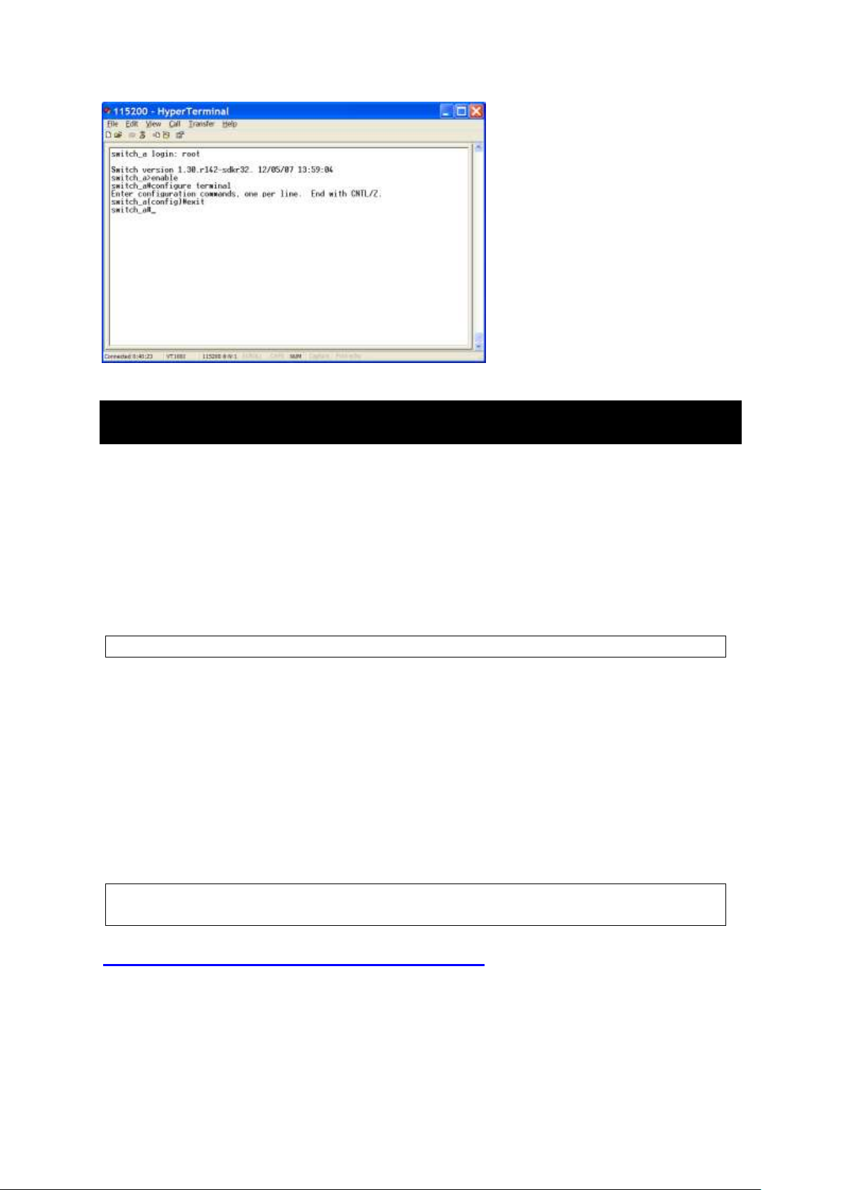
switch_a(config)#
switch_a(config)#hostname switch
switch(config)#
System
System Information, System Name/Password, IP Address, ARP Table, Route
Table, Save Configuration, Firmware Upgrade, Alarm Setting, Reboot, Logout
System Name/Password
System Name:
1. Command Mode: Configure mode
Logon to Configure Mode (Configure Terminal Mode).
The switch_a(config)# prompt will show on the screen.
2. Usage:
Use hostname command to set or change the network server name.
Use the no hostname command to disable this function.
3. Command Syntax:
(no) hostname HOSTNAME
HOSTNAME specifies the network name of the system.
4. Example:
The following example sets the hostname to switch, and shows the change in the prompt:
Password:
1. Command Mode: Configure mode
Logon to Configure Mode (Configure Terminal Mode).
The switch_a(config)# prompt will show on the screen.
User Manual Page 82
Page 83
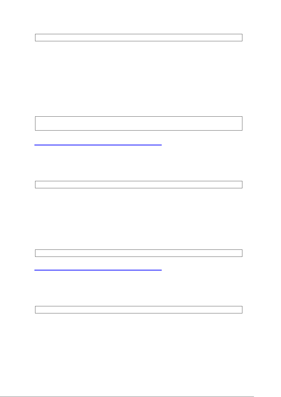
switch_a(config)#
switch_a(config)#enable password mypasswd
switch_a(config)#
switch_a(config)#
switch_a#show arp-table
switch_a(config)#
2. Usage:
Use enable password command to modify or create a password to be used when
entering the Enable mode.
3. Command Syntax:
enable password PASSWORD
PASSWORD specifies the new password of the system.
4. Example:
The following example sets the new password mypasswd to switch:
ARP Table
1. Command Mode: Privileged Exec mode
Logon to Privileged Exec Mode (Enable Mode).
The switch_a# prompt will show on the screen.
2. Usage:
Use show arp-table command to view ARP Table.
3. Command Syntax:
show arp-table
4. Example:
The following example shows the ARP Table of switch:
Route Table
1. Command Mode: Privileged Exec mode
Logon to Privileged Exec Mode (Enable Mode).
The switch_a# prompt will show on the screen.
2. Usage:
Use show route-table command to view Route Table.
3. Command Syntax:
show route-table
User Manual Page 83
Page 84
4. Example:
switch_a#show route-table
switch_a(config)#interface vlan1.1
switch_a(config-if)#
switch_a(config)#interface vlan1.1
switch_a(config-if)#ip address 192.168.1.10/24
switch_a(config-if)#
switch_a(config)#
The following example shows the Route Table of switch:
IP Address
IP Address/IP Subnet Mask:
1. Command Mode: Interface mode
Logon to Configure Mode (Configure Terminal Mode).
Then logon to Interface mode.
vlan1.1 means vlan 1.
The switch_a(config-if)# prompt will show on the screen.
2. Usage:
Use ip address command to set the IP address of an interface.
Use the no ip address command to remove the IP address from an interface.
3. Command Syntax:
ip address IP-ADDRESS
no ip address IP-ADDRESS
no ip address
IP-ADDRESS A.B.C.D/M specifies the IP address and prefix length of an interface.
M specifies IP subnet mask, 8: 255.0.0.0, 16:255.255.0.0, 24: 255.255.255.0.
4. Example:
The following example sets the new IP address 192.168.1.10 and new IP subnet mask
255.255.255.0 to switch:
Default Gateway:
1. Command Mode: Configure mode
Logon to Configure Mode (Configure Terminal Mode).
The switch_a(config)# prompt will show on the screen.
2. Usage:
Use ip default-gateway command to set the IP address of the default gateway.
Use the no ip default-gateway command to remove the IP address of the default
gateway.
User Manual Page 84
Page 85

3. Command Syntax:
switch_a(config)#ip default-gateway 192.168.1.254
switch_a(config)#
switch_a(config)#
switch_a(config)#ip dns 192.168.1.100
switch_a(config)#
switch_a#
ip default-gateway IP-ADDRESS
no ip default-gateway
IP-ADDRESS A.B.C.D specifies the IP address of the default gateway.
4. Example:
The following example sets the default gateway 192.168.1.254 to switch:
DNS Server:
1. Command Mode: Configure mode
Logon to Configure Mode (Configure Terminal Mode).
The switch_a(config)# prompt will show on the screen.
2. Usage:
Use ip dns command to set the IP address of the DNS server.
Use the no ip dns command to remove the IP address of the DNS server.
3. Command Syntax:
ip dns IP-ADDRESS
no ip dns
IP-ADDRESS A.B.C.D specifies the IP address of the DNS server.
4. Example:
The following example sets the DNS server 192.168.1.100 to switch:
Save Configuration
Load config from TFTP server:
1. Command Mode: Privileged Exec mode
Logon to Privileged Exec Mode (Enable Mode).
The switch_a# prompt will show on the screen.
2. Usage:
Use install image command to load configuration file from tftp server to switch.
3. Command Syntax:
install image IP-ADDRESS WORD
IP-ADDRESS specifies the IP address of tftp server.
User Manual Page 85
Page 86
WORD specifies the file name to be loaded to switch.
switch_a#install image 192.168.1.100 flash.tgz
switch_a#
switch_a#
switch_a#write config-file 192.168.1.20
switch_a#
switch_a#
switch_a#copy running-config startup-config
4. Example:
The following example specifies upgrading firmware (file name: flash.tgz) from tftp server
(IP address: 192.168.1.100) to switch:
Load config to TFTP server:
1. Command Mode: Privileged Exec mode
Logon to Privileged Exec Mode (Enable Mode).
The switch_a# prompt will show on the screen.
2. Usage:
Use write config-file command to backup configuration file to tftp server.
3. Command Syntax:
write config-file IP-ADDRESS
IP-ADDRESS specifies the IP address of tftp server.
4. Example:
The following example backups configuration file to tftp server (IP address: 192.168.1.20):
Save Configuration:
1. Command Mode: Privileged Exec mode
Logon to Privileged Exec Mode (Enable Mode).
The switch_a# prompt will show on the screen.
2. Usage:
Use copy running-config startup-config command to write configurations to the file to
be used at startup. This is the same as the write memory command.
3. Command Syntax:
copy running-config startup-config
4. Example:
The following example specifies writing configurations to the file to be used at startup to
switch:
User Manual Page 86
Page 87
switch_a#
switch_a#
switch_a#restore default
switch_a#
switch_a(config)#
switch_a(config)#service auto-config enable
switch_a(config)#no service auto-config enable
switch_a(config)#
Restore Default:
1. Command Mode: Privileged Exec mode
Logon to Privileged Exec Mode (Enable Mode).
The switch_a# prompt will show on the screen.
2. Usage:
Use restore default command to restore default setting of the switch.
3. Command Syntax:
restore default
4. Example:
The following example restores default setting of the switch:
Auto Save:
1. Command Mode: Configure mode
Logon to Configure Mode (Configure Terminal Mode).
The switch_a(config)# prompt will show on the screen.
2. Usage:
Use this command to enable auto save configuration function. The configuration will be
automatically saved at every configured interval while this command is enabled. Use the
no form of this command to disable this feature.
3. Command Syntax:
service auto-config enable
no service auto-config enable
4. Example:
The following example enables or disables auto save configuration to switch:
Auto Save Interval (5~65536 sec):
User Manual Page 87
Page 88
1. Command Mode: Configure mode
switch_a(config)#
switch_a(config)#service auto-config interval 10
switch_a(config)#
switch_a#
switch_a#install image 192.168.1.100 flash.tgz
switch_a#
Logon to Configure Mode (Configure Terminal Mode).
The switch_a(config)# prompt will show on the screen.
2. Usage:
Use this command to set the interval when the configuration would be automatically
saved. The range of interval value is from 5 to 65535. And the default value is 30 seconds.
3. Command Syntax:
service auto-config interval WORD
WORD specifies the interval value.
4. Example:
The following example sets the interval WORD (10) when the configuration would be
automatically saved to switch:
Firmware Upgrade
1. Command Mode: Privileged Exec mode
Logon to Privileged Exec Mode (Enable Mode).
The switch_a# prompt will show on the screen.
2. Usage:
Use install image command to upgrade firmware from tftp server to switch.
3. Command Syntax:
install image IP-ADDRESS WORD
IP-ADDRESS specifies the IP address of tftp server.
WORD specifies the file name to be upgraded to switch.
4. Example:
The following example specifies upgrading firmware (file name: flash.tgz) from tftp server
(IP address: 192.168.1.100) to switch:
Please follow the message on the screen during the firmware upgrade process. Do not
turn off the power or perform other functions during this period of time.
User Manual Page 88
Page 89
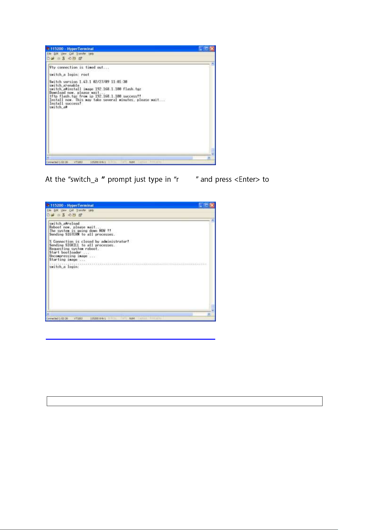
switch_a(config)#
# eload reboot the switch
after completing the upgrade process.
Alarm Setting
Alarm-trigger if:
1. Command Mode: Configure mode
Logon to Configure Mode (Configure Terminal Mode).
The switch_a(config)# prompt will show on the screen.
2. Usage:
Use this command to enable or disable alarm trigger on interface.
3. Command Syntax:
(no) alarm-trigger if INTERFACE
INTERFACE specifies the interface.
User Manual Page 89
Page 90

4. Example:
switch_a(config)#alarm-trigger if fe1
switch_a(config)#
switch_a(config)#
switch_a(config)#alarm-trigger power 1
switch_a(config)#
switch_a#
switch_a#reload
switch_a login:
The following example enables alarm trigger on interface fe1 to switch:
Alarm-trigger power:
1. Command Mode: Configure mode
Logon to Configure Mode (Configure Terminal Mode).
The switch_a(config)# prompt will show on the screen.
2. Usage:
Use this command to enable or disable alarm trigger of power source.
3. Command Syntax:
(no) alarm-trigger power POWER
POWER specifies the power source.
4. Example:
The following example enables alarm trigger of power 1 to switch:
Reboot
1. Command Mode: Privileged Exec mode
Logon to Privileged Exec Mode (Enable Mode).
The switch_a# prompt will show on the screen.
2. Usage:
Use reload command to restart switch.
3. Command Syntax:
reload
4. Example:
The following example specifies restarting switch:
User Manual Page 90
Page 91

Logout
switch_a>
switch_a#
switch_a>logout
switch_a login:
1. Command Mode: Exec mode or Privileged Exec mode
Logon to Exec Mode (View Mode) or Privileged Exec Mode (Enable Mode).
The switch_a> or switch_a# prompt will show on the screen.
2. Usage:
Use logout command to exit from the Exec mode or Privileged Exec mode.
3. Command Syntax:
logout
4. Example:
The following example specifies to exit from the Exec mode or Privileged Exec mode.
User Manual Page 91
Page 92
Port
switch_a(config)#interface fe1
switch_a(config-if)#
switch_a(config)#interface fe1
switch_a(config-if)#shutdown
switch_a(config-if)#
switch_a(config)#interface fe1
switch_a(config-if)#
Configuration, Port Status, Rate Control, RMON Statistics, Per Port Vlan
Activities
Configuration
Admin Setting:
1. Command Mode: Interface mode
Logon to Configure Mode (Configure Terminal Mode).
Then logon to Interface mode.
fe1 means port 1.
The switch_a(config-if)# prompt will show on the screen.
2. Usage:
Use the shutdown command to shut down the selected interface.
Use the no shutdown to disable this function.
3. Command Syntax:
(no) shutdown
4. Example:
The following example shows the use of the shutdown command to shut down the
interface fe1 (port 1):
Duplex:
1. Command Mode: Interface mode
Logon to Configure Mode (Configure Terminal Mode).
Then logon to Interface mode.
fe1 means port 1.
The switch_a(config-if)# prompt will show on the screen.
2. Usage:
Use duplex command to specify the duplex mode to be used for each interface.
Use the no duplex to disable this function.
3. Command Syntax:
(no) duplex MODE
User Manual Page 92
Page 93
MODE specifies the duplex mode: auto, full, half.
switch_a(config)#interface fe1
switch_a(config-if)#duplex full
switch_a(config-if)#
switch_a(config)#interface fe1
switch_a(config-if)#
switch_a(config)#interface fe1
switch_a(config-if)#flowcontrol on
switch_a(config-if)#
switch_a>
switch_a#
4. Example:
The following example shows the use of duplex MODE (full) to the interface fe1 (port 1):
Flow control:
1. Command Mode: Interface mode
Logon to Configure Mode (Configure Terminal Mode).
Then logon to Interface mode.
fe1 means port 1.
The switch_a(config-if)# prompt will show on the screen.
2. Usage:
Use flowcontrol on command to enable flow control, and configure the flow control
mode for the port.
Use the no flowcontrol to disable this function.
3. Command Syntax:
flowcontrol on
no flowcontrol
4. Example:
The following example shows the use of flowcontrol on to the interface fe1 (port 1):
Port Status
1. Command Mode: Exec mode or Privileged Exec mode
Logon to Exec Mode (View Mode) or Privileged Exec Mode (Enable Mode).
The switch_a> or switch_a# prompt will show on the screen.
2. Usage:
Use the show interface command to display interface configuration and status.
User Manual Page 93
Page 94

3. Command Syntax:
switch_a>show interface fe1
switch_a#
switch_a#show sfp-alarm-trigger ge1
switch_a(config)#
show interface IFNAME
IFNAME specifies the name of the interface for which status and configuration
information is desired.
4. Example:
The following example shows the use of show interface to display interface configuration
and status of the interface fe1 (port 1):
Alarm Situation:
1. Command Mode: Privileged Exec mode
Logon to Privileged Exec Mode (Enable Mode).
The switch_a# prompt will show on the screen.
2. Usage:
Use the show sfp-alarm-trigger command to show the information of SFP alarm trigger
including temperature, Vcc, Tx_bias, Tx_pow and Rx_pow.
3. Command Syntax:
show sfp-alarm-trigger IFNAME
IFNAME specifies the name of the interface for which status and configuration
information is desired.
4. Example:
The following example shows the use of show sfp-alarm-trigger to display the
information of SFP alarm trigger of the interface ge1 (port G1):
Temperature Alarm (Warning) Threshold:
1. Command Mode: Configure mode
Logon to Configure Mode (Configure Terminal Mode).
The switch_a(config)# prompt will show on the screen.
2. Usage:
Use this command to set temperature alarm (warning) threshold for SFP transceiver.
3. Command Syntax:
sfp set-temp IFNAME high-alarm|high-warning|low alarm|low warning LEVEL
IFNAME specifies the name of the interface for which status and configuration
information is desired.
User Manual Page 94
Page 95
LEVEL Threshold value -128 ~ 128℃.
switch_a(config)#sfp set-temp ge1 high-alarm 100
switch_a(config)#
switch_a(config)#
switch_a(config)#sfp set-vcc ge1 high-alarm 6
switch_a(config)#
switch_a(config)#
4. Example:
The following example sets high temperature alarm threshold 100℃ for SFP transceiver
of interface ge1 (port G1):
Voltage Alarm (Warning) Threshold:
1. Command Mode: Configure mode
Logon to Configure Mode (Configure Terminal Mode).
The switch_a(config)# prompt will show on the screen.
2. Usage:
Use this command to set voltage alarm (warning) threshold for SFP transceiver.
3. Command Syntax:
sfp set-vcc IFNAME high-alarm|high-warning|low alarm|low warning LEVEL
IFNAME specifies the name of the interface for which status and configuration
information is desired.
LEVEL Threshold value 0 ~ 6.55 volts.
4. Example:
The following example sets high voltage alarm threshold 6 volts for SFP transceiver of
interface ge1 (port G1):
Tx-bias Alarm (Warning) Threshold:
1. Command Mode: Configure mode
Logon to Configure Mode (Configure Terminal Mode).
The switch_a(config)# prompt will show on the screen.
2. Usage:
Use this command to set transmitter laser bias alarm (warning) threshold for SFP
transceiver.
3. Command Syntax:
sfp set-tx-bias IFNAME high-alarm|high-warning|low alarm|low warning LEVEL
IFNAME specifies the name of the interface for which status and configuration
information is desired.
User Manual Page 95
Page 96
LEVEL Threshold value 0 ~ 131 mA.
switch_a(config)#sfp set-tx-bias ge1 high-alarm 131
switch_a(config)#
switch_a(config)#
switch_a(config)#sfp set-tx-pow ge1 high-alarm 8.16
switch_a(config)#
switch_a(config)#
4. Example:
The following example sets high transmitter laser bias alarm threshold 131 mA for SFP
transceiver of interface ge1 (port G1):
Tx-pow Alarm (Warning) Threshold:
1. Command Mode: Configure mode
Logon to Configure Mode (Configure Terminal Mode).
The switch_a(config)# prompt will show on the screen.
2. Usage:
Use this command to set transmitted output power alarm (warning) threshold for SFP
transceiver.
3. Command Syntax:
sfp set-tx-pow IFNAME high-alarm|high-warning|low alarm|low warning LEVEL
IFNAME specifies the name of the interface for which status and configuration
information is desired.
LEVEL Threshold value -30 ~ 8.16 dbm.
4. Example:
The following example sets high transmitted output power alarm threshold 8.16 dbm for
SFP transceiver of interface ge1 (port G1):
Rx-pow Alarm (Warning) Threshold:
1. Command Mode: Configure mode
Logon to Configure Mode (Configure Terminal Mode).
The switch_a(config)# prompt will show on the screen.
2. Usage:
Use this command to set received optical power alarm (warning) threshold for SFP
transceiver.
3. Command Syntax:
sfp set-rx-pow IFNAME high-alarm|high-warning|low alarm|low warning LEVEL
IFNAME specifies the name of the interface for which status and configuration
User Manual Page 96
Page 97
information is desired.
switch_a(config)#sfp set-rx-pow ge1 high-alarm 8.16
switch_a(config)#
switch_a(config)#interface fe1
switch_a(config-if)#
switch_a(config)#interface fe1
switch_a(config-if)#rate-control ingress 10m
switch_a(config-if)#
switch_a>
LEVEL Threshold value -30 ~ 8.16 dbm.
4. Example:
The following example sets high received optical power alarm threshold 8.16 dbm for SFP
transceiver of interface ge1 (port G1):
Rate Control
1. Command Mode: Interface mode
Logon to Configure Mode (Configure Terminal Mode).
Then logon to Interface mode.
fe1 means port 1.
The switch_a(config-if)# prompt will show on the screen.
2. Usage:
Use this command to specify the ingress/egress rate to be used for each interface. The
bandwidth value is in bits.
Use the no parameter with this command to remove the ingress/egress rate to be used for
each interface.
3. Command Syntax:
(no) rate-control ingress/egress VALUE
VALUE
<1-10000000000 bits> (usable units: k, m, g)
<1-999>k|m for 1 to 999 kilo bits or mega bits.
1g for 1 giga bits.
4. Example:
The following example shows the use of rate-control ingress VALUE (10 mega bits) to the
interface fe1 (port 1):
RMON Statistics
1. Command Mode: Exec mode or Privileged Exec mode
Logon to Exec Mode (View Mode) or Privileged Exec Mode (Enable Mode).
The switch_a> or switch_a# prompt will show on the screen.
User Manual Page 97
Page 98

switch_a#
switch_a>show interface statistics fe1
switch_a>
switch_a#
switch_a>show vlan 2
2. Usage:
Use the show interface statistics command to display RMON statistics of interface.
3. Command Syntax:
show interface statistics IFNAME
IFNAME specifies the name of the interface for which RMON statistics is desired.
4. Example:
The following example shows the use of show interface statistics to display RMON
statistics of the interface fe1 (port 1):
Per Port Vlan Activities
1. Command Mode: Exec mode or Privileged Exec mode
Logon to Exec Mode (View Mode) or Privileged Exec Mode (Enable Mode).
The switch_a> or switch_a# prompt will show on the screen.
2. Usage:
Use show vlan command to display information about a particular VLAN by specifying the
VLAN ID.
3. Command Syntax:
show vlan <2-4094>
<2-4094> VLAN ID.
4. Example:
The following is an output of show vlan command displaying information about VLAN 2:
User Manual Page 98
Page 99
Switching
switch_a(config)#
switch_a(config)#bridge 1 ageing-time 1000
switch_a(config)#
switch_a(config)#interface fe1
switch_a(config-if)#
Bridging, Static MAC Entry, Port Mirroring, PoE, PoE Scheduling
Bridging
Aging Time (seconds):
1. Command Mode: Configure mode
Logon to Configure Mode (Configure Terminal Mode).
The switch_a(config)# prompt will show on the screen.
2. Usage:
Use this command to specify an ageing-out time for a learned MAC address. The learned
MAC address will persist till this specified time.
3. Command Syntax:
Bridge GROUP ageing-time AGEINGTIME
no bridge GROUP ageing-time
Group = <1-1> The ID of the bridge-group that this ageing time is for.
AGEINGTIME = <10-1000000> The number of seconds of persistence.
4. Example:
The following example sets the new AGEINGTIME (1000) to bridge GROUP (1):
Threshold level (0-100):
1. Command Mode: Interface mode
Logon to Configure Mode (Configure Terminal Mode).
Then logon to Interface mode.
fe1 means port 1.
The switch_a(config-if)# prompt will show on the screen.
2. Usage:
Use storm-control level command to specify the rising threshold level for broadcasting,
multicast, or destination lookup failure traffic. The storm control action occurs when traffic
utilization reaches this level.
3. Command Syntax:
storm-control level LEVEL
LEVEL <0-100> specifies the percentage of the threshold; percentage of the maximum
speed (pps) of the interface.
User Manual Page 99
Page 100
switch_a(config)#interface fe1
switch_a(config-if)#storm-control level 30
switch_a(config-if)#
switch_a(config)#interface fe1
switch_a(config-if)#
switch_a(config)#interface fe1
switch_a(config-if)#storm-control broadcast enable
switch_a(config-if)#
switch_a(config)#interface fe1
switch_a(config-if)#
4. Example:
The following example shows setting storm-control level LEVEL (30) to the interface fe1
(port 1):
Broadcast:
1. Command Mode: Interface mode
Logon to Configure Mode (Configure Terminal Mode).
Then logon to Interface mode.
fe1 means port 1.
The switch_a(config-if)# prompt will show on the screen.
2. Usage:
Use storm-control broadcast enable command to enable broadcast traffic.
Use no storm-control broadcast command to disable broadcast traffic.
3. Command Syntax:
storm-control broadcast enable
no storm-control broadcast
4. Example:
The following example shows setting storm-control broadcast enable to the interface
fe1 (port 1):
Multicast:
1. Command Mode: Interface mode
Logon to Configure Mode (Configure Terminal Mode).
Then logon to Interface mode.
fe1 means port 1.
The switch_a(config-if)# prompt will show on the screen.
2. Usage:
Use storm-control multicast enable command to enable multicast traffic.
User Manual Page 100
 Loading...