

Page 1

LevelOne
GSW-0504
GSW-0804
5/8-Port Gigabit Switch
with internal power
User Manual
Version 2.0-0710
Page 2

Page 3

Table of Contents
Introduction.................................................................. 1
Features......................................................................................................1
Package Contents.......................................................................................2
Hardware Description.................................................. 3
Front Panel.................................................................................................. 3
Rear Panel.................................................................................................. 3
LED Indicators............................................................................................. 4
Installation.................................................................... 6
Network Application.................................................... 7
Technical Specification............................................... 8
Appendix..................................................................... 10
10 /100BASE-TX Pin outs.........................................................................10
10/100Base-TX Cable Schematic .............................................................11
10/100/1000Base-TX Pin outs .................................................................. 12
10/100/1000Base-TX Cable Schematic ....................................................12
Page 4

Introduction
The GSW-0504/0804 5/8-Port Gigabit Switch is an ideal solution for
solving traffic block at the core of the network. It offers 5/8 auto-negotiation
10/100/1000Base-T Gigabit Ethernet ports which can significantly improve
your network backbone performance. Besides, this Switch will fit into any
enterprise level network to act as an exit to the backbone switch.
The GSW-0504/0804 5/8-Port Gigabit Switch features Auto MDI/MDIX
function for each port. [In general, MDI means connecting to another Hub
or Switch while MDIX means connecting to a workstation or PC. Therefore,
Auto MDI/MDIX means that you can connect to another switch or
workstation without changing non-crossover or crossover cabling. ]
Besides, it also features a store-and-forward switching and can auto-learn
and store source address on a 4K MAC address table.
Features
Conforms to IEEE 802.3, 802.3u, 802.3ab and 802.3x
5 / 8-port 10/100/1000 Mbps Gigabit Switch with internal power
Automatic MDI/MDIX crossover for all ports
4K entry MAC address table
1Mbit Memory buffer
Back-plane:
¾ 5 port: 10Gbps back-plane
¾ 8 port: 16Gbps back-plane
N-Way Auto-Negotiation
Back pressure half duplex
Flow control full duplex
True non-blocking switching
Store-and-Forward architecture support
1
Page 5
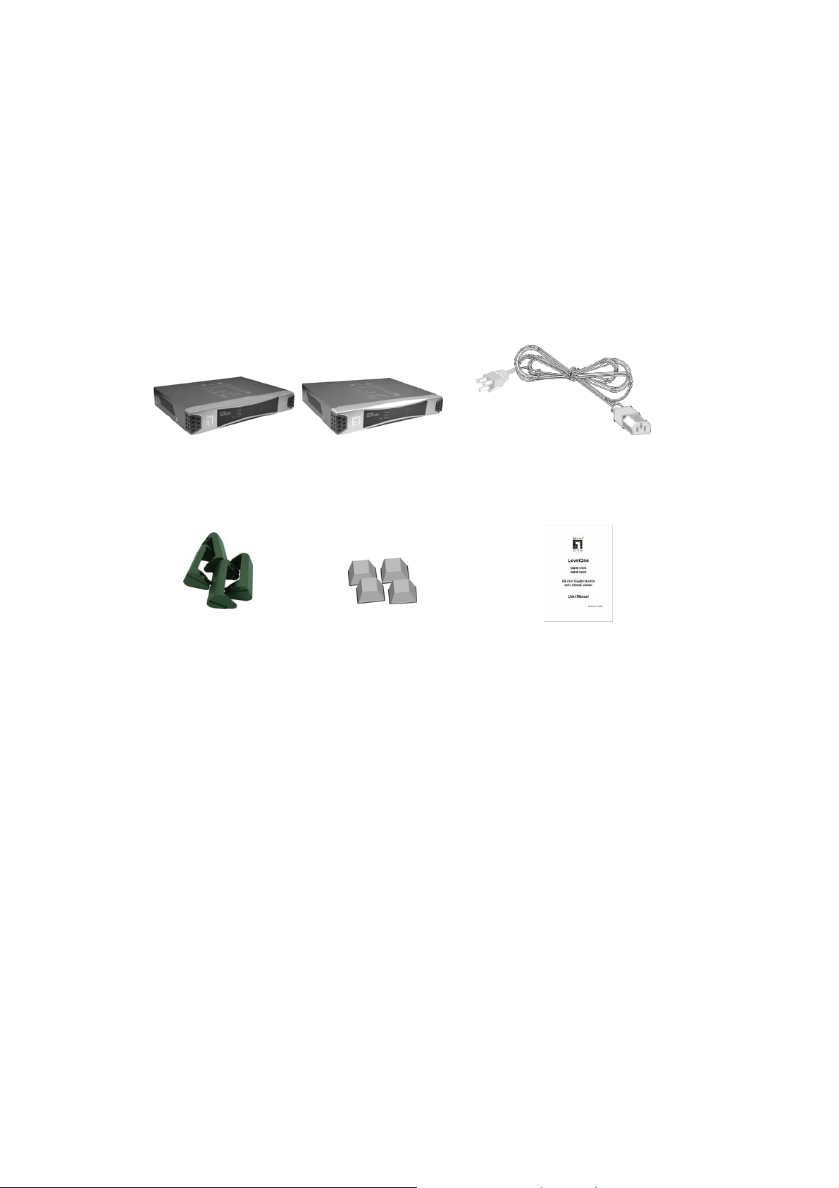
Package Contents
5 / 8-port 10/100/1000 Mbps Gigabit Switch with internal power
Power Cord
Four Rubber Feet
Stackable Kits
User’s Manual
5/8-Port Gigabit Switch w/internal power Power Cord
Stackable Kits Rubber Feet User Manual
Figure 1-1. Package Contents
Compare the contents of your 5 / 8-port 10/100/1000 Mbps Gigabit Switch
package with the standard checklist above. IF any item is missing or
damaged, please contact your local dealer for service.
2
Page 6
Hardware Description
This Section describes the hardware of the 5/8-Port Gigabit Switch.
Front Panel
The Front Panel of the 5/8-Port Gigabit Switch consists of LED-indicators
(100/1000, Link/Activity, Full duplex/Collision) for each Gigabit port and
power LED-indicator for unit. The details of LED indicator description refer
to the LED Indicator section.
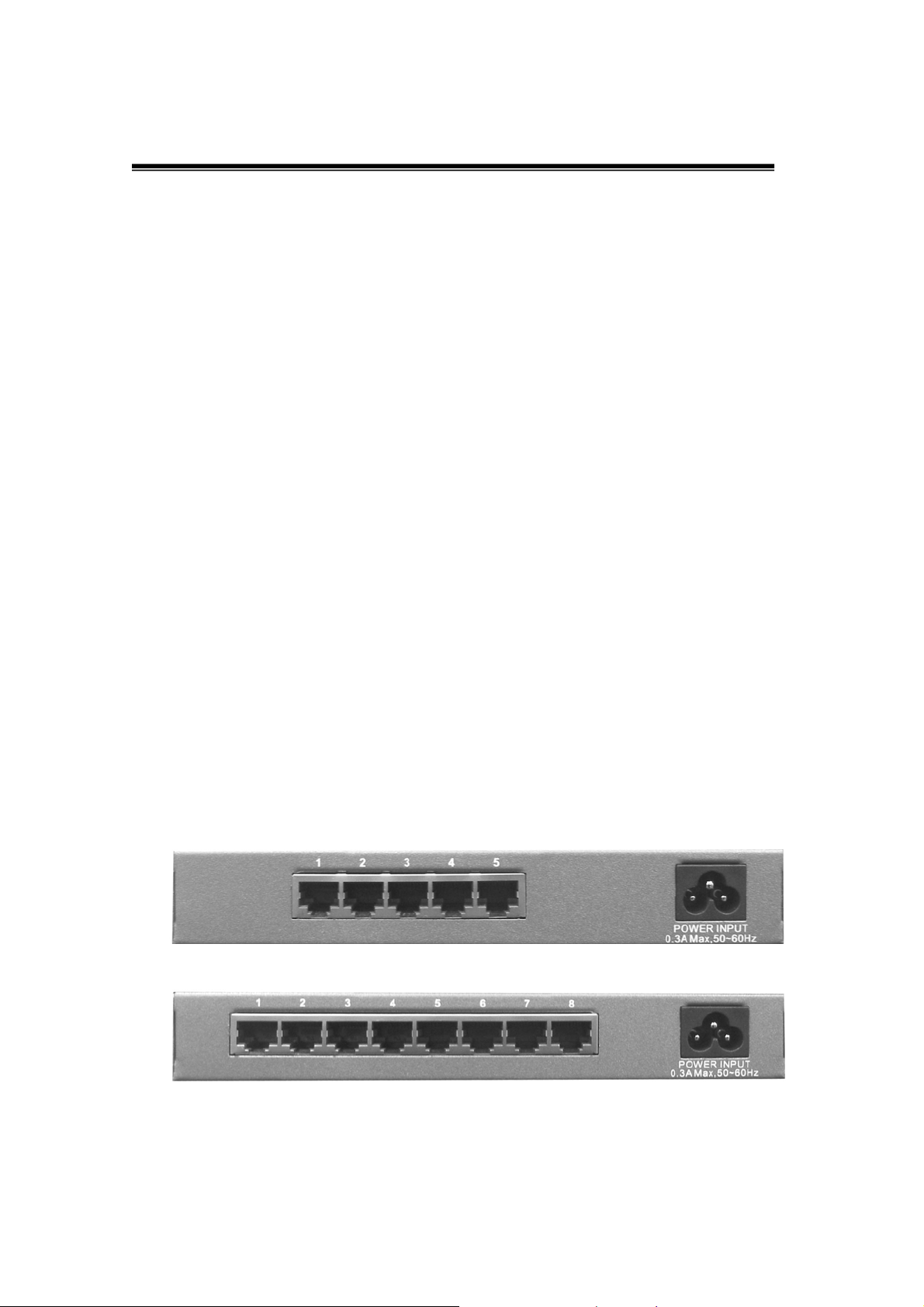
Rear Panel
The Rear Panel of the 5/8-port Gigabit Switch consists of 5/8
auto-negotiation 10/100/1000Mbps Ethernet RJ-45 connectors.
RJ-45 Ports (Auto MDI/MDIX): 5/8-port auto-negotiation 10/100/1000
Mbps Ethernet RJ-45 connectors
[Auto MDI/MDIX means that you can connect to another switch or
workstation without changing straight through or crossover cabling.]
Figure 2-2. The Rear Panel of the 5/8 Port Gigabit Switch
3
Page 7
LED Indicators
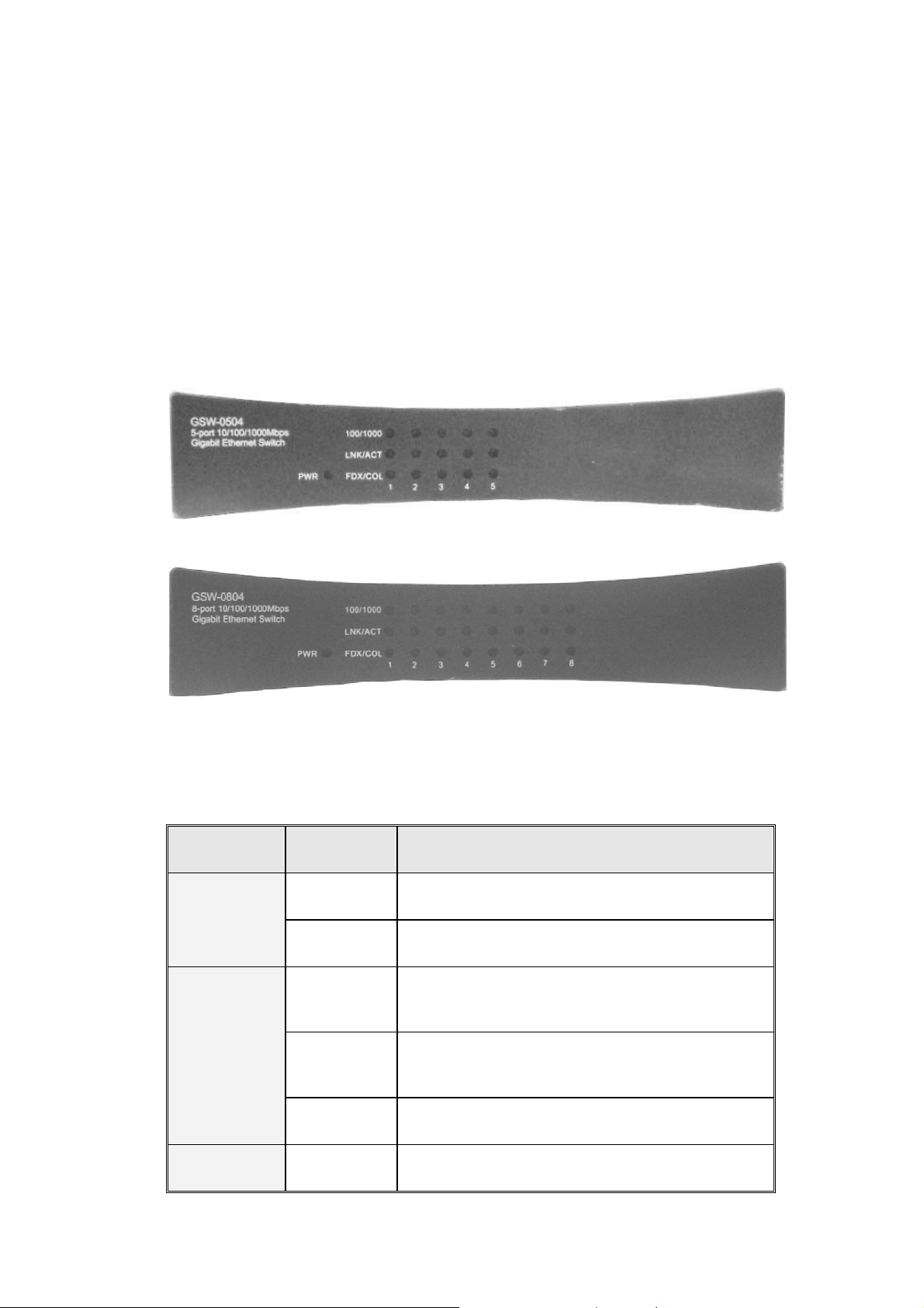
The LED Indicators gives a real-time indication of system operating
statuses. There are 3 LED-indicators (100/1000, LNK/ACT, FDX/COL) for
each Gigabit port and one Power LED for unit. The following table
provides descriptions of LEDs status and their meaning.
Figure 2-3.LED Indicators
LED Status Description
Green Power On
Power
Off Power is not connected
The port is operating at the speed of
Green
1000Mbps.
100/1000
LNK/ACT
The port is operating at the speed of
Orange
100Mbps.
Off No device attached or in 10Mbps mode
Green The port is connecting with the device.
4
Page 8

Blinking The port is receiving or transmitting data.
Off No device attached.
Orange The port is operating in Full-duplex mode.
FDX/COL
Blinking Packet collision occurred on this port.
Off No device attached or in half-duplex mode.
Table 2-1. The Descriptions of LED Indicators
5
Page 9

Installation
This section shows the installation procedures of the switch.
Set the Switch on a sufficiently large flat space with a power outlet nearby.
The surface where you put your Switch should be clean, smooth, level, and
sturdy. Make sure there is enough clearance around the Switch to allow
attachment of cables, power cord and air circulation.
Attaching Rubber Feet
A. Make sure mounting surface on the bottom of the Switch is grease and
dust free.
B. Remove adhesive backing from your Rubber Feet.
C. Apply the Rubber Feet to each corner on the bottom of the Switch.
These footpads can prevent the Switch from shock/vibration.
Power On
Connect the power cord to the power socket on the rear panel of the
Switch. The other side of power cord connects to the power outlet. Check
the power indicator on the front panel to see if power is properly supplied.
6
Page 10

Network Application
This section provides you one sample of network topology in which the
5/8-Port Gigabit Switch is used. In general, the 5/8-Port Gigabit Switch is
designed as a high-bandwidth backbone switch.
You can use the 5/8-Port Gigabit Switch to connect servers, switches,
workstation, and PCs (Of course, the Gigabit 1000Base-T NIC has
installed into the PC) to each other by connecting these devices directly to
the Switch. The Switch automatically learns node address, which are
subsequently used to filter and forward all traffic based on the destination
address.
For enterprise networks where large data broadcast are constantly
processed, this switch is an ideal suitable for departmental switches to
connect to the core switch.
All ports can connect to departmental switches, and the departmental
switches can be connected to the 5/8-Port Gigabit Switch. Then all the
devices in this network can communicate with each other. Connecting
servers to the core switch allow each end station to access the server’s
data.
This switch is an ideal solution for backbone connectivity. In the above
example, servers, department switches, and workstation are directly
connected to the Core Switch, 5/8-Port Gigabit Switch.
7
Page 11
Technical Specification
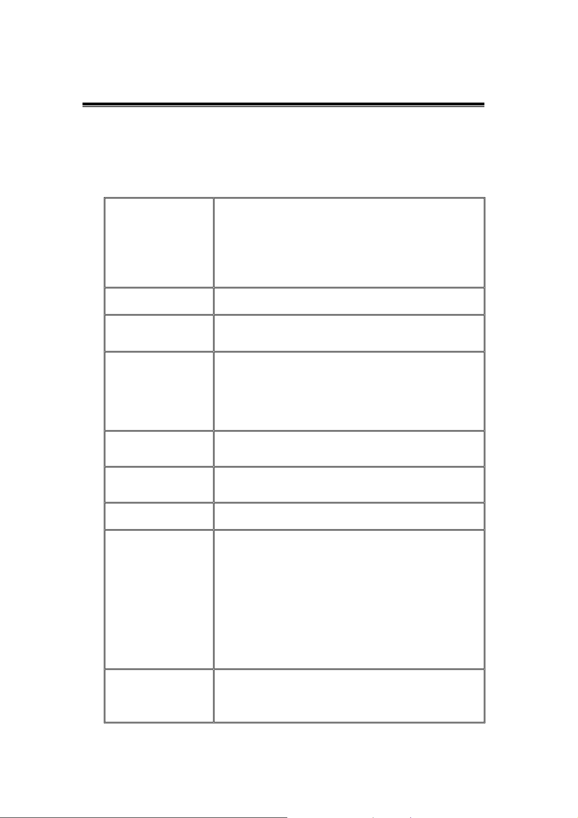
The following table provides the technical specification of 5/8 ports Gigabit
Copper Switch.
IEEE 802.3 10BASE-T Ethernet,
IEEE 802.3u 100BASE-TX Fast Ethernet
Standard
IEEE 802.3ab Gigabit Ethernet
IEEE802.3x Flow Control and Back-pressure
Protocol
Technology
Transfer Rate
Connector
MAC Address
Memory Buffer
CSMA/CD
Store-and-Forward switching architecture
14,880 pps for 10Mbps
148,800 pps for 100Mbps
1,488,000 pps for 1000Mbps
5/8 Gigabit Copper: RJ-45; Auto-MDIX on all ports
8K Mac address table
112KB (GSW-0504); 114KB (GSW-0804)
10BASE-T: 2-pair UTP/STP Cat. 3, 4, 5 cable
EIA/TIA-568 100-ohm (100m)
Network Cable
Back plane
100BASE-TX: 2-pair UTP/STP CAT. 5 cable
EIA/TIA-568 100-ohm (100m)
Gigabit Copper: 4 pair UTP/STP CAT. 5 cable
EIA/TIA 568 100-ohm (100M)
5 port: 10Gbps
8 port: 16Gbps
8
Page 12
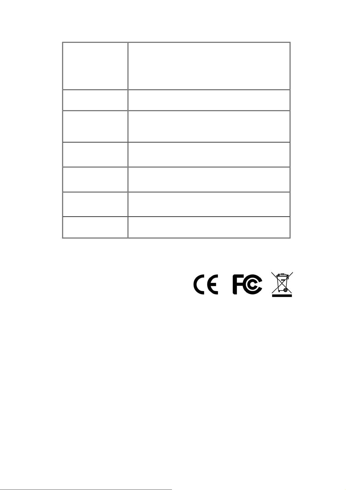
Per port: 100/1000, Link/Activity, Full duplex/
LED
Power Supply
Power
Consumption
Operation
Temperature
Operation
Humidity
Dimension
EMI
Collision
Per unit: Power
100~240VAC, 50~60Hz,internal power
5 port: 9.6Watt (maximum)
8 port: 12.8Watt (maximum)
0℃ to 45℃ (32℉ to 113℉)
10% to 90% (Non-condensing)
199mm x 147mm x 31.5 mm (W x D x H)
CE
9
Page 13
Appendix
10 /100BASE-TX Pin outs
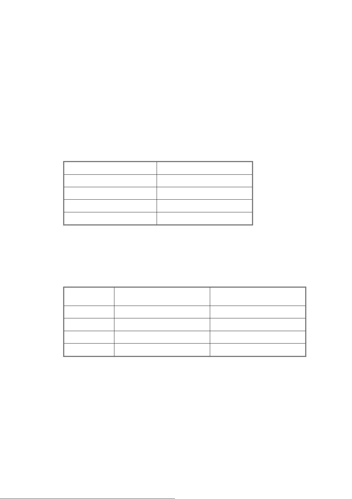
With10 /100BASE-TX cable, pins 1 and 2 are used for transmitting data,
and pins 3 and 6 for receiving data.
RJ-45 Pin Assignments
Pin Number Assignment
1 Tx+
2 Tx3 Rx+
6 Rx-
Note: “+” and “-” signs represent the polarity of the wires that make up
each wire pair.
The table below shows the 10 / 100BASE-TX MDI and MDI-X port pin outs.
Pin MDI-X Signal Name MDI Signal Name
1 Receive Data plus (RD+) Transmit Data plus (TD+)
2 Receive Data minus (RD-) Transmit Data minus (TD-)
3 Transmit Data plus (TD+) Receive Data plus (RD+)
6 Transmit Data minus (TD-) Receive Data minus (RD-)
10
Page 14
10/100Base-TX Cable Schematic
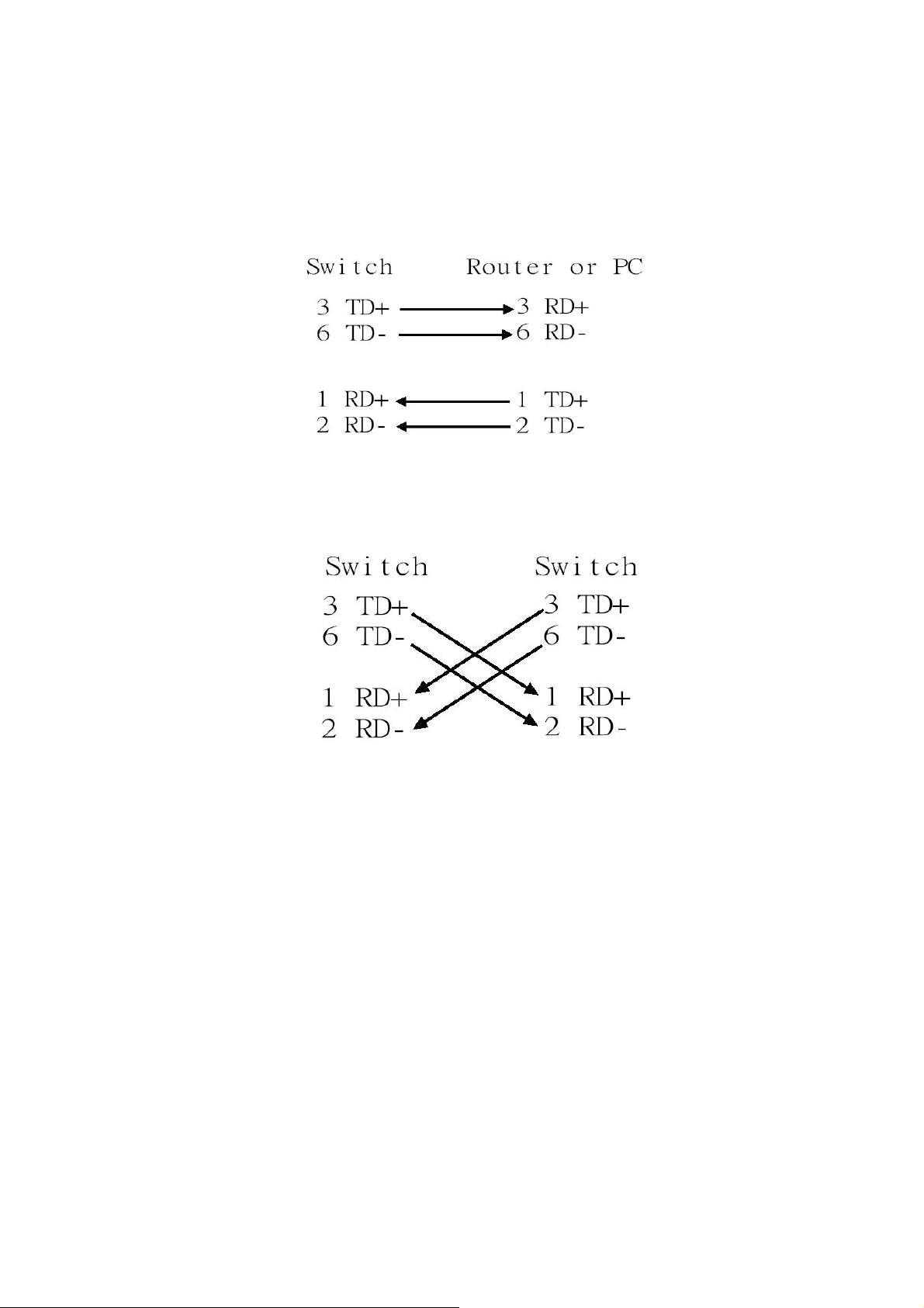
The following two figures show the 10/100Base-TX cable schematic.
Straight-through cable schematic
Cross over cable schematic
11
Page 15
10/100/1000Base-TX Pin outs
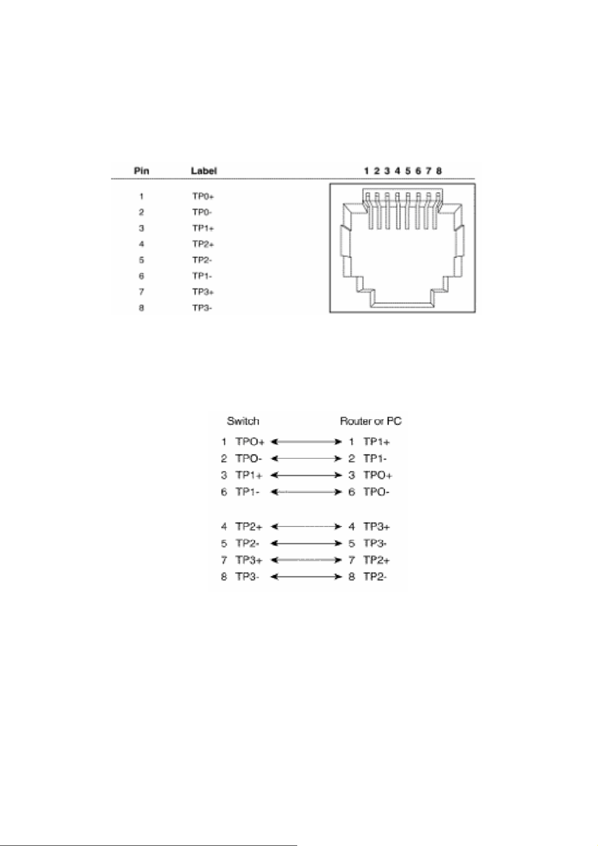
The following figure shows the 10/100/1000 Ethernet RJ-45 pin outs.
10/100/1000Base-TX Cable Schematic
Straight through cables schematic
12
Page 16
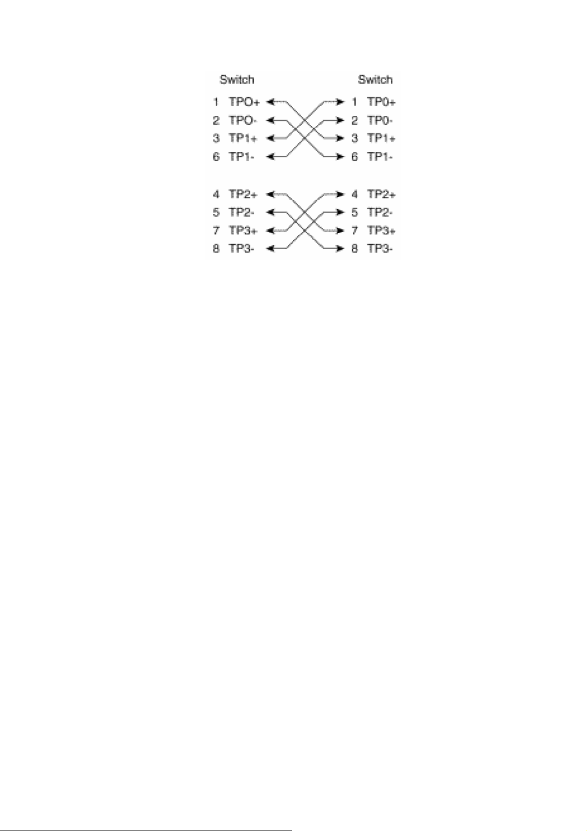
Cross over cables schematic
13
 Loading...