

Page 1

LevelOne GSW-0800TXM
Expandable 10/100/1000 Mbps
Managed Switch
User’s Manual
Page 2

Preface
FCC Warning
This device has been tested and found to comply with limits for a Class A
digital device, pursuant to Part 15 of the FCC Rules. These limits are
designed to provide reasonable protection against harmful interference when
the equipment is operated in a commercial environment. This equipment
generates, uses and can radiate radio frequency energy and, if not installed
and used in accordance with the user’s manual, may cause interference in
which case the user will be required to correct the interference at his own
expense.
CE Mark Warning
This is a Class A product. In a domestic environment, this product may cause
radio interference in which case the user may be required to take adequate
measures.
Notice
1. Product Name Alias
The convention of this manual will refer to this product as Expandable
10/100/1000 Mbps Managed Switch or simply as the Switch, instead of the
original product model name.
2. Specifications issue
Specifications are subject to change without notice.
Page 3

Table of Contents
CHAPTER 1 INTRODUCTION..................................................... 1-2
About LevelOne GSW-0800TXM Expandable 10/100/1000 Mbps
Managed Switch..................................................................... 1-2
Key Features ..................................................................................................... 1-3
Front Panel Display Highlights.........................................................................1-3
Optional Modules ................................................................... 1-4
MDU-2101SX ...................................................................................................1-4
MDU-2801TX...................................................................................................1-4
MDU-2802FXC................................................................................................ 1-5
MDU-2401FXC................................................................................................ 1-5
Unit Overview......................................................................... 1-6
Front Panel Layout............................................................................................1-6
Front Panel Display........................................................................................1-6
Rear Panel Layout.............................................................................................1-7
CHAPTER 2 INSTALLATION ...................................................... 2-2
Rack Mounting ....................................................................... 2-2
Installing Optional Modules ..................................................... 2-3
Quick Configuration ................................................................ 2-4
Front Panel Display Configuration ................................................................... 2-5
Console Management Configuration ................................................................ 2-7
Console Screens ............................................................................................. 2-8
Connecting Network Devices..................................................2-10
Connecting Fast Ethernet Hubs.......................................................................2-10
Connecting Workstations................................................................................2-12
Connecting Fiber Ports....................................................................................2-13
Connecting Gigabit Devices ...........................................................................2-14
CHAPTER 3 FRONT PANEL DISPLAY MANAGEMENT .............. 3-2
User Interface ........................................................................ 3-2
Front Panel Display Features............................................................................3-2
Front Panel Display Key Usage ........................................................................3-3
Front Panel Display Main Menu Circle ............................................................ 3-4
Message Zone ....................................................................... 3-4
Port Group Indicators .............................................................. 3-5
Observing Basic Port Information ............................................ 3-7
Port Indicator Definitions..................................................................................3-8
Power-On Self Test ................................................................ 3-8
Menu Tree ............................................................................. 3-9
Exiting the Menu Tree .................................................................................... 3-12
Page 4

Utilization ..............................................................................3-12
Collision ................................................................................3-14
Select Group.........................................................................3-15
Statistics ...............................................................................3-16
Statistics Counters........................................................................................3-19
Port Status ............................................................................3-20
Status Indicators...........................................................................................3-21
All Ports Status................................................................................................3-22
Single Port Status............................................................................................3-23
Port Setting ...........................................................................3-24
Auto-Negotiation ............................................................................................ 3-24
Port Setting Options.....................................................................................3-25
Configuring Port Settings................................................................................3-25
User Authentication ..................................................................................... 3-26
Selecting a Port ............................................................................................3-26
Unit Configuration..................................................................3-28
Unit Configuration Options............................................................................3-29
User Authentication ..................................................................................... 3-29
Loop Detect.....................................................................................................3-30
Console Lock ..................................................................................................3-31
Lock the Console .........................................................................................3-31
Unlock the Console......................................................................................3-32
Network Configuration ................................................................................... 3-33
Network Configuration Options...................................................................3-33
Configuring the Parameters .........................................................................3-33
IP Address....................................................................................................3-34
Subnet Mask.................................................................................................3-35
Default Gateway .......................................................................................... 3-35
Set Password ...................................................................................................3-35
System Restart.................................................................................................3-36
System Default................................................................................................3-37
System Information................................................................3-38
CHAPTER 4 SETTING-UP FOR CONSOLE MANAGEM ENT........ 4-2
Managing The Switch ............................................................. 4-2
Console Program...............................................................................................4-2
Setting-Up the Terminal Program..................................................................4-3
Power On Self Test........................................................................................4-7
Navigating the Console Program Screens.........................................................4-8
Login Screen .....................................................................................................4-9
User Name and Password .............................................................................. 4-9
Main Menu...................................................................................................4-10
POST Download Menu...................................................................................4-11
TFTP Server IP Address..............................................................................4-12
Network Configuration ................................................................................ 4-12
Page 5

Boot ROM Code Download.........................................................................4-12
System Software & Web Pages Database Download .................................. 4-12
POST Commands.........................................................................................4-12
CHAPTER 5 CONSOLE MANAGEMENT..................................... 5-2
Introduction ............................................................................ 5-2
Using a Telnet Session......................................................................................5-2
Navigating the Console Program Screens.........................................................5-3
Getting Started....................................................................... 5-3
Login Screen.......................................................................... 5-3
User Name and Password ................................................................................. 5-4
Main Menu ............................................................................. 5-5
Help Menu ............................................................................. 5-5
System Information................................................................. 5-6
Management Setup ................................................................ 5-8
Network Configuration ..................................................................................... 5-9
Serial Port Configuration ................................................................................ 5-10
SNMP Community Setup................................................................................5-11
Trap Receiver Menu........................................................................................5-13
Management Capability Setup........................................................................5-14
Trap Filter Setup .............................................................................................5-15
Device Control.......................................................................5-16
Switch Configuration ...................................................................................... 5-17
Switch Port Configuration ..............................................................................5-18
Switch Port Configuration Overview Menu ................................................ 5-18
Switch Port Configuration Menu.................................................................5-20
Permanent Address Configuration .................................................................. 5-21
Permanent Address Configuration Menu (View) ........................................5-22
Permanent Address Configuration Menu (Edit)..........................................5-22
Spanning Tree Protocol Configuration ........................................................... 5-24
Spanning Tree Protocol Port Configuration....................................................5-26
Port Statistics...................................................................................................5-27
User Authentication ...............................................................5-29
User Authentication Menu (Edit)................................................................. 5-30
User Authentication Menu -2-.....................................................................5-32
System Utility........................................................................5-33
System Restart.................................................................................................5-34
System Restart Menu (Confirm)..................................................................5-35
Factory Reset...................................................................................................5-36
Factory Reset Menu (Confirm)....................................................................5-38
Login Timeout.................................................................................................5-39
System Download...........................................................................................5-40
System Download Notes..............................................................................5-40
Executing a System Download....................................................................5-41
Technical Specifications .......................................................... A-1
5
Page 6

Menu Tree .............................................................................B-1
Glossary ................................................................................C-1
Index .....................................................................................D-1
Page 7

Chapter
In this chapter, you will be
8Port 10/100Mbps
characteristics of the Switch and
1
Introduction
introduced to the LevelOne
GSW-0800TXM
SNMP Switch. You will find
information about the physical
an introduction to its features.
Page 8
1-2 Introduction
Chapter 1 Introduction
About LevelOne GSW-0800TXM
8 Port 10/100Mbps SNMP Switch
The LevelOne GSW-0800TXM 8Port 10/100 Mbps SNMP Switch is
designed to meet the requirement for today’s growing network. With optional
modules the number and type of ports can be increased from the built-in 8TX ports up to 24 TX and FX ports in combination. It features flexible
management functions using the Front Panel Display, console management
or the Network Management Interface. Users can monitor utilization,
collision ratio, statistic counters, port status, and configure the switch.
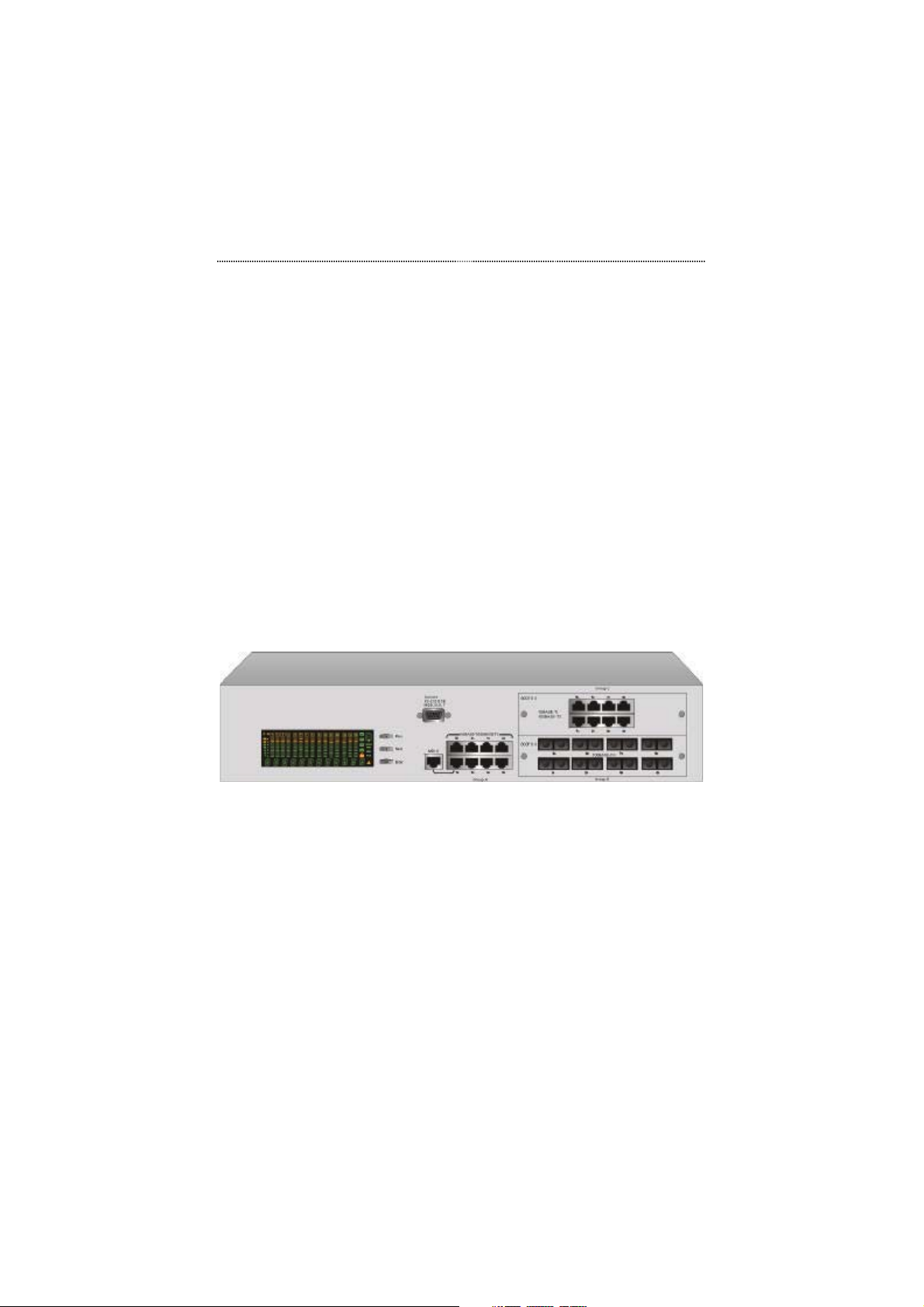
Figure 1.1 LevelOne GSW-0800TXM 8 Port 10/100 Mbps SNMP Switch
The LevelOne GSW-0800TXM 8 Port 10/100 Mbps SNMP Switch provides
8 10/100 Mbps ports and one shared Uplink port for flexible system
integration. 8-TX ports, 1-SX ports,4-FX ports or 8-FX ports can be added
with optional modules and be automatically configured by the system.
The LevelOne GSW-0800TXM 8 Port 10/100 Mbps SNMP Switch is fully
Plug and Play compliant.
Page 9

Introduction
1-3
Key Features
Designed for high-performance, high port density and cost-effectiveness, the
LevelOne GSW-0800TXM 8 Port 10/100 Mbps Managed Switch provides
the following key features:
• 2-Optional Module Slots
• One Uplink port shared with port 1
• 8 10/100 Mbps Ports (auto negotiation, half/full, store-and-forward
modes)
• Smart Front Panel Display operation for easy configuration and
monitoring.
• Flow control to prevent packet loss
• MAC addresses learning capability - Up to 12K
• Password locking function prevents unauthorized access.
• Non-blocking architecture
• Self-diagnostics
• 128K per port RAM buffer
• 4.8Giga-bps system-wide bandwidth
• Web-based management
• Optional Modules:
MDU-2101SX: 1 port Gigabit module
MDU-2801TX: 8 port 100BASE-TX module
MDU-2802FXC: 8 port 100BASE-FX module
MDU-2401FXC: 4 port 100BASE-FX module
Front Panel Display Highlights
• Device and port configuration, management & statistics monitoring
through an easy to use menu
• Traffic utilization and collision ratio indication on all the ports
• Status monitoring such as; speed, duplex mode, switching mode, on all
ports
• Panel Keys to perform all Front Panel Display functions
• Password locking of the Front Panel Display to prevent unauthorized
access
Page 10
1-4 Introduction
Optional Modules
The Switch provides you with the following four module options.
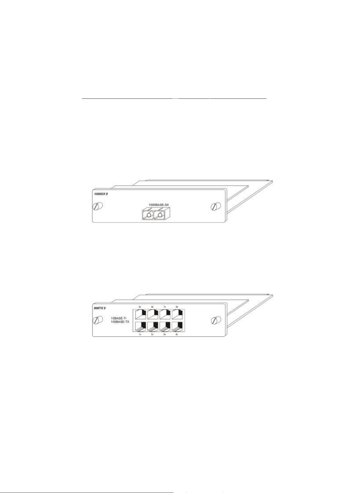
MDU-2101SX
Figure 1.2 The MDU-2101SX
The MDU-2101SX uses gigabit technology to provide you with 1000 Mbps
backbone connections. The module features a single MMF SC connector.
MDU-2801TX
Figure 1.3 MDU-2801TX
The dual speed MDU-2801TX provides you with 8 100BASE-TX/ 10BASET Ethernet switch ports. All ports use a standard RJ-45 connector.
Page 11
Introduction
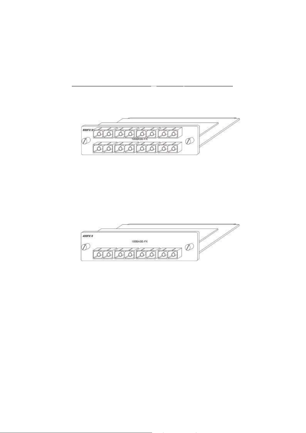
MDU-2802FXC
Figure 1.4 MDU-2802FXC
The MDU-2802FXC provides you with 8 100BASE-FX Fast Ethernet switch
ports. This module is excellent for connecting downstream switch hubs. All
ports use SC fiber connectors.
MDU-2401FXC
1-5
Figure 1.5 MDU-2401FXC
The MDU-2401FXC provides you with 4 100BASE-FX Fast Ethernet switch
ports. All ports use SC fiber connectors.
Page 12
1-6 Introduction
Unit Overview
Front Panel Layout
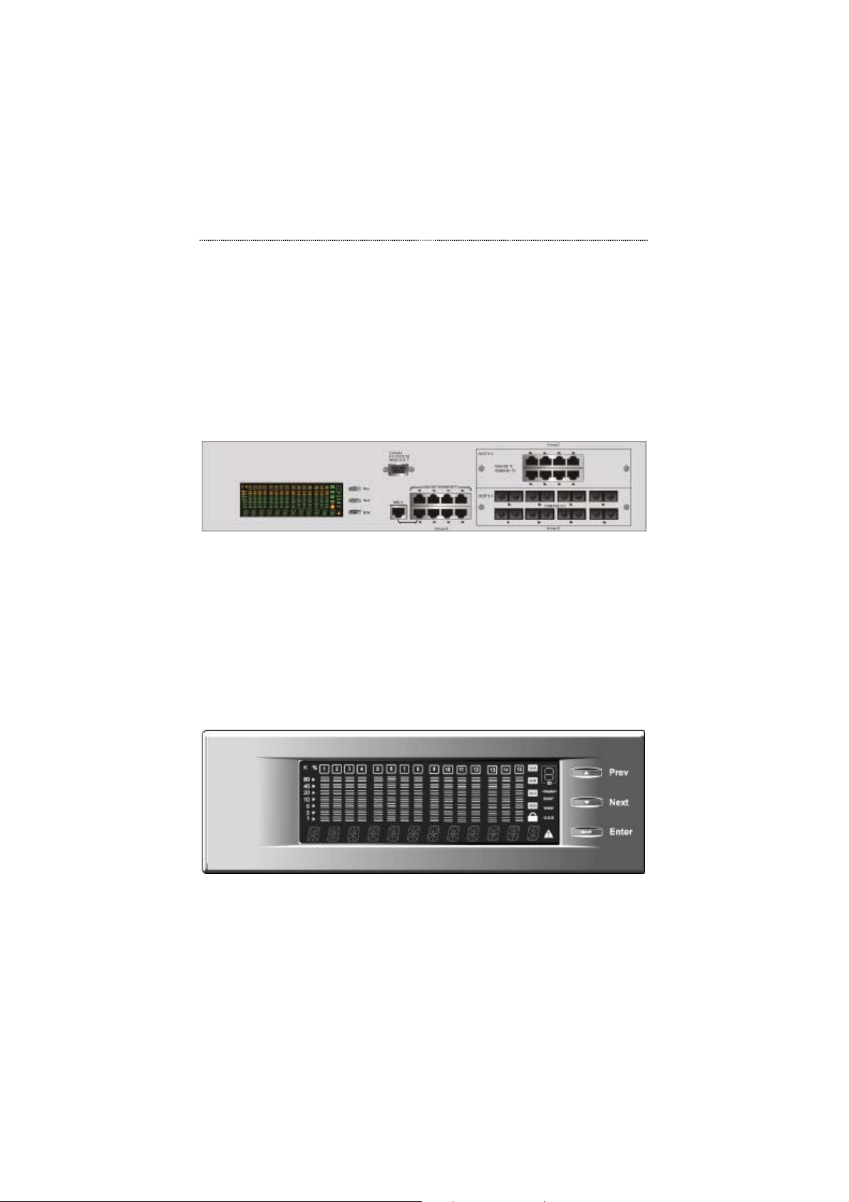
The front panel features the Front Panel Display, Panel Keys and ports.
Figure 1.6 Ethernet Switch Front Panel
Front Panel Display
The Front Panel Display includes a high definition display and the Panel
Keys that enable users to easily monitor and configure the system. The Front
Panel Display provides diagnostic functions that include port settings, status
monitoring, traffic utilization, collision and error rate.
Figure 1.7 Front Panel Display
Using the Panel Keys, users are able to configure all the ports simultaneously
Page 13
Introduction
or individually and monitor all switch settings.
Rear Panel Layout
The AC power socket is located on the rear panel.
Figure 1.8 Rear Panel
1-7
Page 14

Chapter
This chapter will provide you with
set the Switch up and offer some
2
Installation
detailed information on how to
rack-mount the Switch, quickly
connectivity suggestions.
Page 15
2-2 Installation
Chapter 2 Installation
Rack Mounting
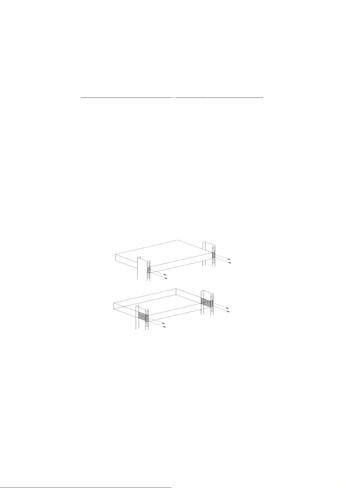
Rack mounting brackets are provided to mount the Switch in standard EIA
19-inch racks.
Align the mounting brackets on the sides of the unit with the slit over the
holes. Secure the screws tightly to affix the brackets to the device. Then,
place the device into the 19” rack and secure it tightly. Please ensure that the
ventilation holes are not blocked.
Figure 2.1 Rack Mounting
Page 16
Installation 2-3
Installing Optional Modules
Power down Switch before installing an optional module. No hardware or
software configuration settings are required. Please read this section carefully
before installing modules.
To install an option module, perform the following steps.
Note: Modules are not hot-swapable. You must remove power from the
switch before installing or replacing a module.
1. Remove the power from the Switch by disconnecting the power
cable from the AC outlet.
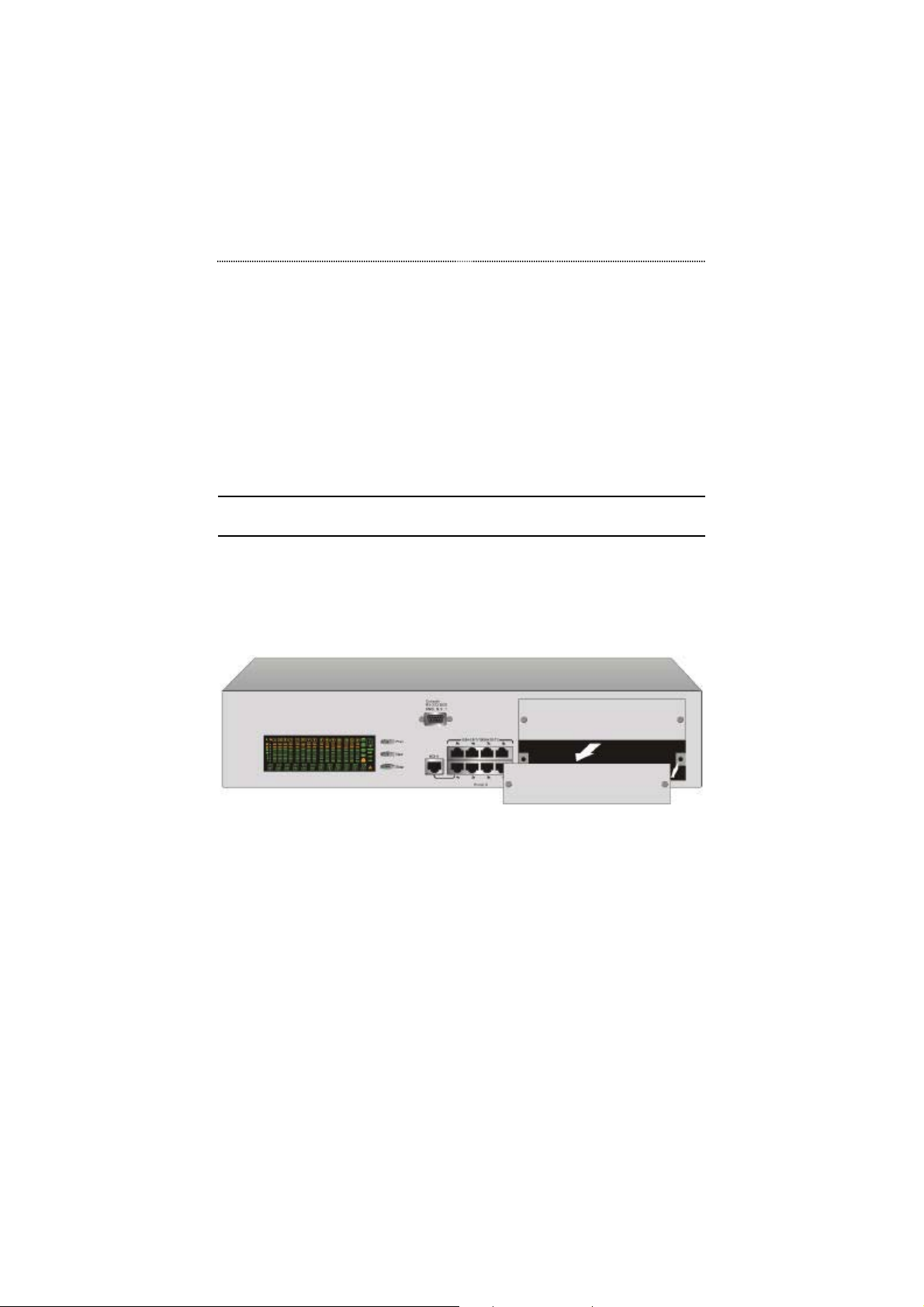
2. Remove blank cover from the module slot by turning the two
knobs on the front counterclockwise as shown in Figure 2.2.
Figure 2.2 Removing the Blank Module Panel
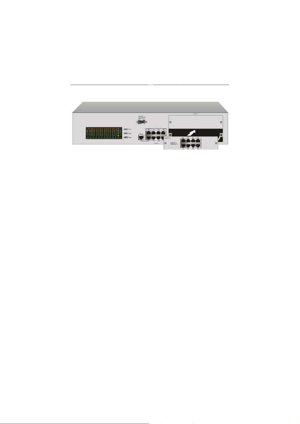
3. Insert the new module, ensuring that the edges slide through the
guides, as shown in Figure 2.3
Page 17
2-4 Installation
Figure 2.3 Insert the Module
4. Turn the two knobs on the new module until they are securely
attached to the Switch.
5. Connect AC power to the switch.
6. Connect the appropriate communication cable to the new
module.
Quick Configuration
Three basic parameters must be set in order to configure the Switch into your
network. The parameters include the IP address, subnet mask and default
gateway. These parameters can be configured via the Front Panel Display or
the Console Management program.
The following two sections provide you with brief configuration instructions
using the Front Panel Display and the Console Management program. For
more detailed instruction, please refer to the appropriate subsequent chapters.
Page 18
Installation 2-5
Front Panel Display Configuration
Menu
Selection
Digit
Input
Enable/
Disable
Using the Front Panel Display Keys
Prev: Scroll backward through menu items
Next: Scroll forward through menu items
Enter: Enter selected menu item
Prev: Scroll through digits (0-9, -)
Next: Select current digit and move to next digit
Enter: Enter selected string of digits
Prev: Scroll backward through menu items
Next: Scroll forward through menu items
Enter: Select current menu item (* displayed)
Page 19
2-6 Installation
g
Figure 2.4 The Main Menu Items
Configuring the Basic Parameters
1. Enter UNIT CONFIG menu
Unlock
Configure
Restart
2. Enter password digit "0000"
3. You will briefly see the PASSED message
1. Enter NETWORK CONF menu
2. Enter IP ADDRESS menu
3. Input IP address digits and press Enter
4. Repeat steps 2 and 3 for SUBNET MASK and
DEF GATEWAY
1. Enter NETWORK CONF menu
2. Enter SYS RESTART menu
3. Press Enter. You will see SYS REBOOT. The
reboot will take several moments. The Switch
is now confi
ured in your network.
Page 20
Installation 2-7
Console Management Configuration
To start using the Console Management program, first connect an EIA-232
serial cable to a COM port on a PC or notebook computer and to the Console
Port on the front panel of the Switch. Note: do not us a null modem cable.
Terminal Program
Baud: 9600
Parity: None
Data bits: 8
Stop bits: 1
Flow control: None
Navigating the Console Program Screens with the
Terminal Keyboard
Tab Key Use the Tab key to select screen menus.
Enter Key
Esc Key Return to the previous menu.
HELP
Press the Enter key after selecting a menu item with the Tab
key to view the selection’s sub-menu.
Select HELP at the bottom of the console screens to view
keyboard commands.
Page 21
2-8 Installation
Console Screens
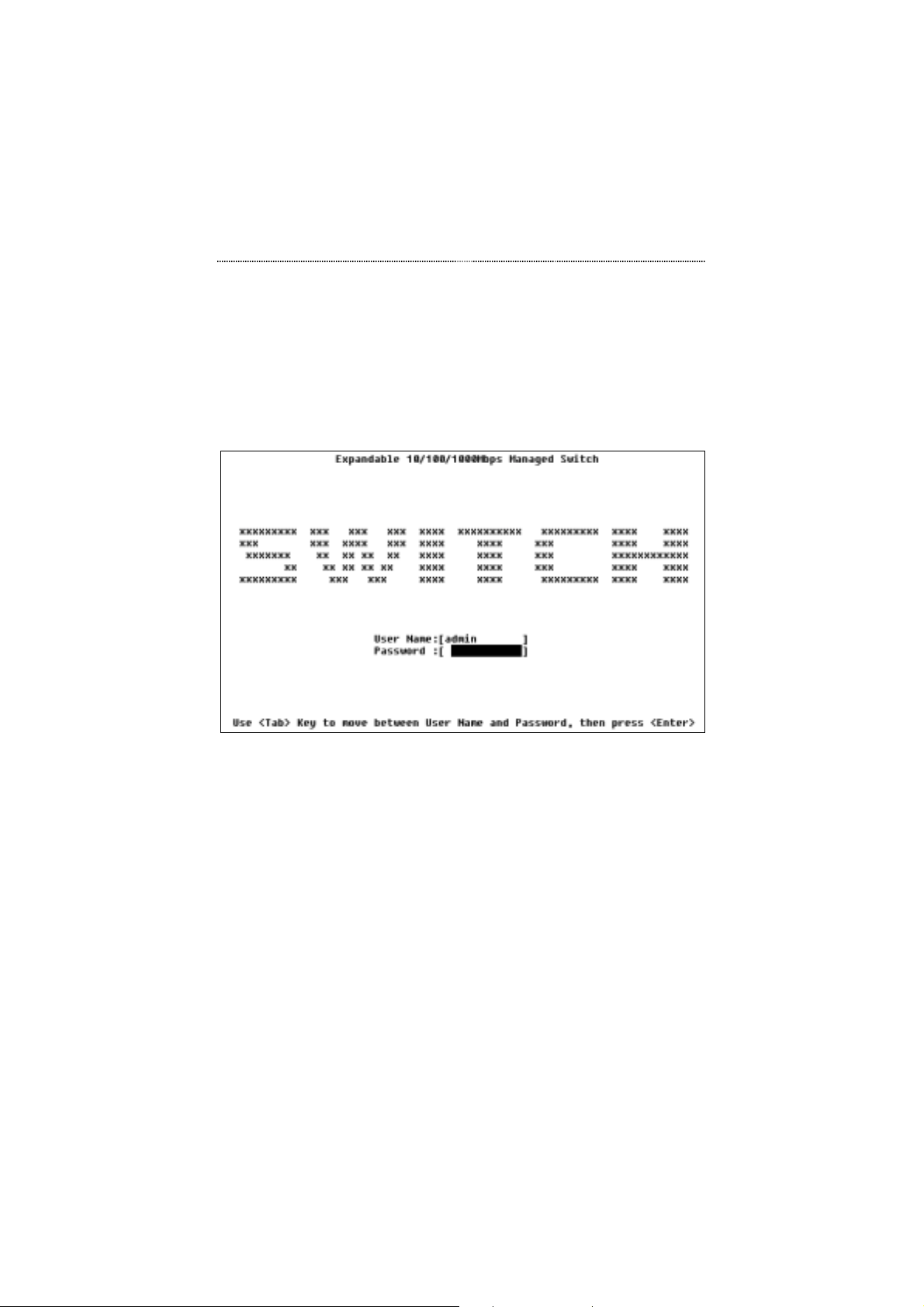
In the Login Screen, you must enter a User Name and Password. The factory
default User name is "admin" and the Password and empty string (i.e. you do
not need to enter a Password).
Figure 2.5 Login Screen
Page 22
Installation 2-9
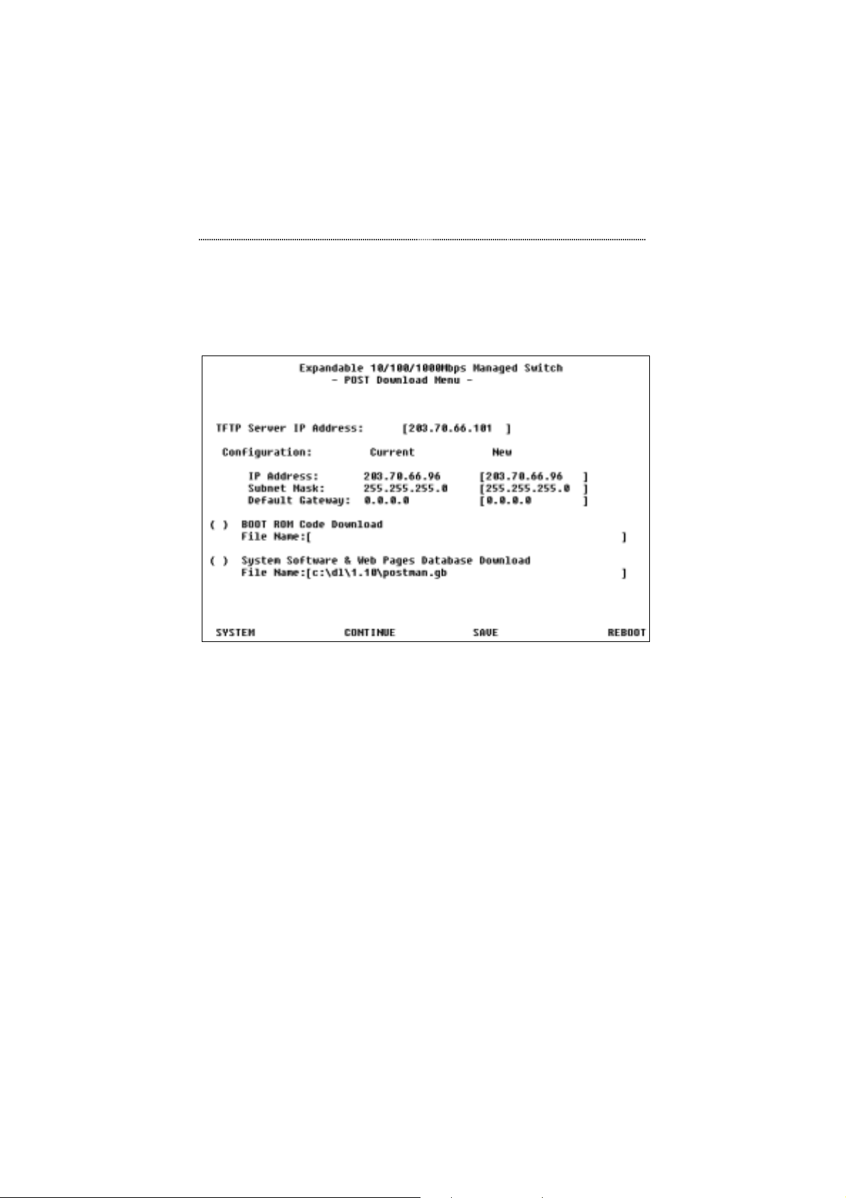
If you are booting the Switch for the first time, you will first see the POST
Download Screen as shown below. This screen allows you to set basic
Switch configurations.
Figure 2.6 POST Download Screen
After the settings are configured, you must restart the Switch. Select
REBOOT in the lower right hand side of the menu to reboot.
For more detailed information, please see Chapter 4, Setting-Up for Console
Management.
Page 23

2-10 Installation
Connecting Network Devices
This section provides you with some connectivity options.
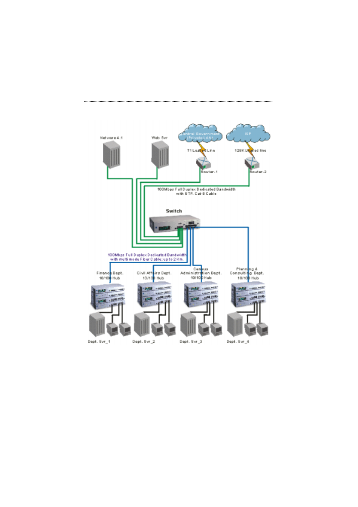
Connecting Fast Ethernet Hubs
The example on page 2-11 shows how 10/100 Mbps hubs can be connected
to the Switch to form a larger network.
Page 24
Installation 2-11
Figure 2.7 Connecting Fast Ethernet Hubs
Page 25
2-12 Installation
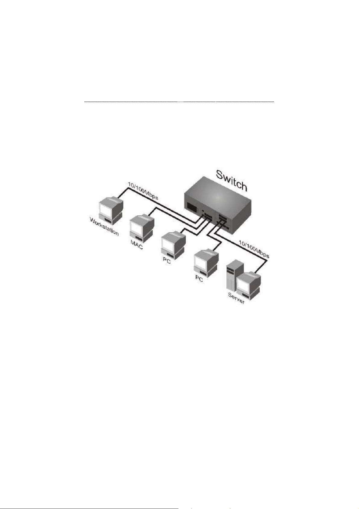
Connecting Workstations
This example shows the Switch directly connected to workstations.
Figure 2.8 Connecting Workstations
Page 26
Installation 2-13
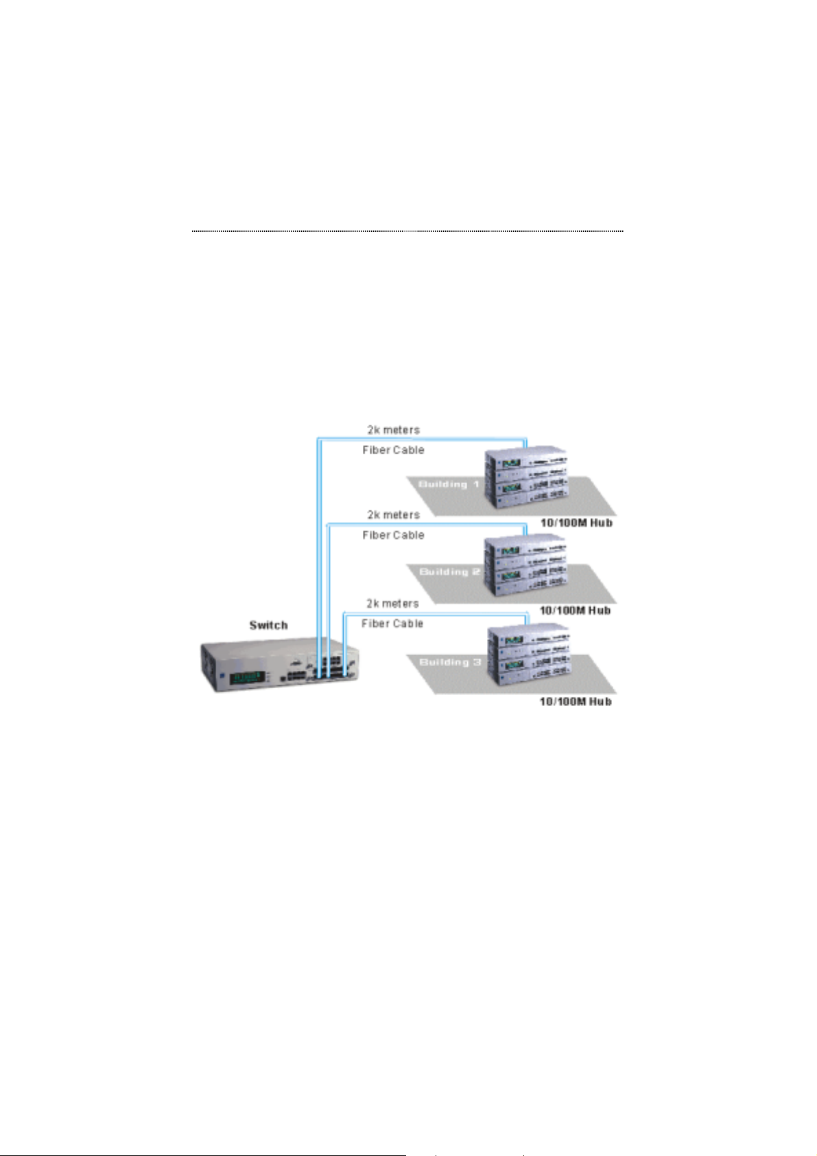
Connecting Fiber Ports
This example shows how the fiber modules can be used for long distance
connections.
Figure 2.9 Connecting Fiber Ports
Page 27
2-14 Installation
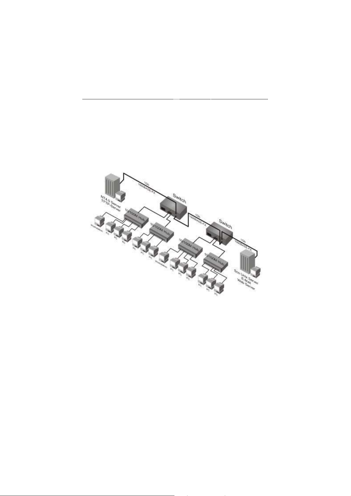
Connecting Gigabit Devices
This example shows how the Gigabit module can be used as a backbone
connection.
Figure 2.10 A Gigabit Backbone Connection
Page 28

Chapter
This chapter will provide you with
he
interface, then take you through
g
3
Front Panel
Display
Mana
complete information about t
Front Panel Display. We will start
with an overview of the
all of the menus and settings.
ement
Page 29
3-2 Front Panel Display Management
Chapter 3 Front Panel Display Management
User Interface
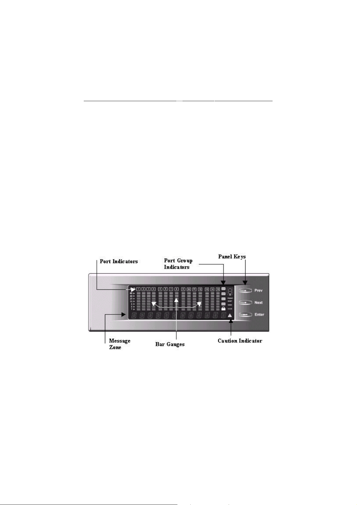
The Front Panel Display is shown in Figure 3.1. It provides you with network
management at your finger tip and allows you to observe real-time traffic and
collision levels at a glance.
Understanding the functions of the Front Panel Display will easily enable the
user to utilize the full power of the Switch to create an efficient network.
Front Panel Display Features
Figure 3.1 Front Panel Display
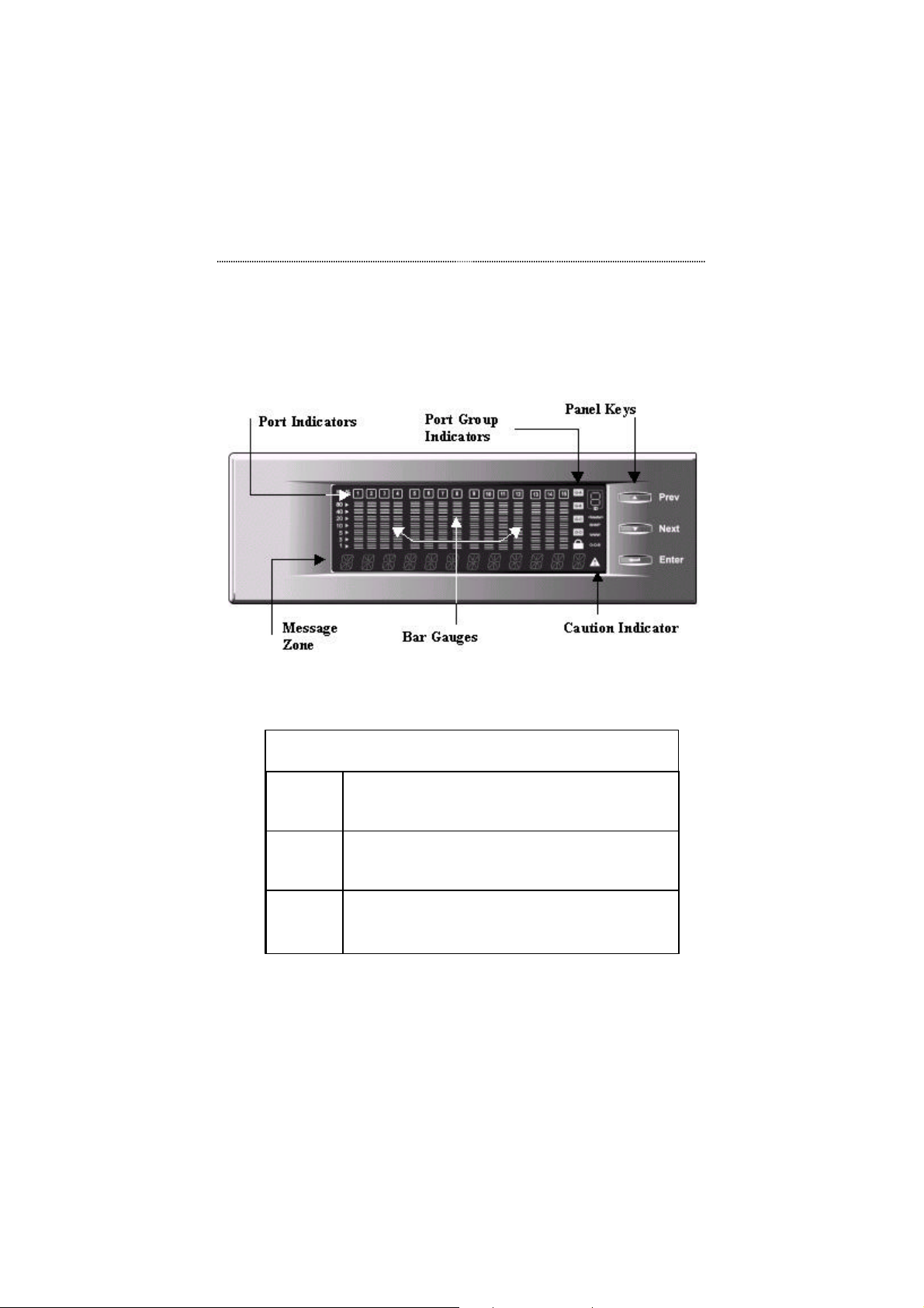
The following table displays the various Front Panel Display indicators and
their meanings.
Page 30

Front Panel Display Management 3-3
Item Indicates
K% Percentage of utilization or collision
Port Indicators Port status information. Please see Observing Basic
Port Information on page 3-7 for more information.
Port Indicator Frame Port status information. Please see Observing Basic
Port Information on page 3-7 for more information.
Bar Gauges Utilization levels, collision levels, status and setting
information depending upon the current menu
Message Zone Displays the menu items and status information
Lock Icon The Front Panel Display is locked or unlocked
Caution Indicator Indicates a device malfunction
G-A Indicates current port icons represent ports in port
group A
G-B Indicates current port icons represent ports in port
group B
G-C Indicates current port icons represent ports in port
group C
Table 3.1 Front Panel Display Indicators
Front Panel Display Key Usage
Menu
Selection
Digit
Input
Enable/
Disable
Using the Front Panel Display Keys
Prev: Scroll backward through menu items
Next: Scroll forward through menu items
Enter: Enter selected menu item
Prev: Scroll through digits (0-9, -)
Next: Select current digit and move to next digit
Enter: Enter selected string of digits
Prev: Scroll backward through menu items
Next: Scroll forward through menu items
Enter: Select current menu item (* displayed)
Table 3.2 Front Panel Display Key Usage
Page 31
3-4 Front Panel Display Management
Front Panel Display Main Menu Circle
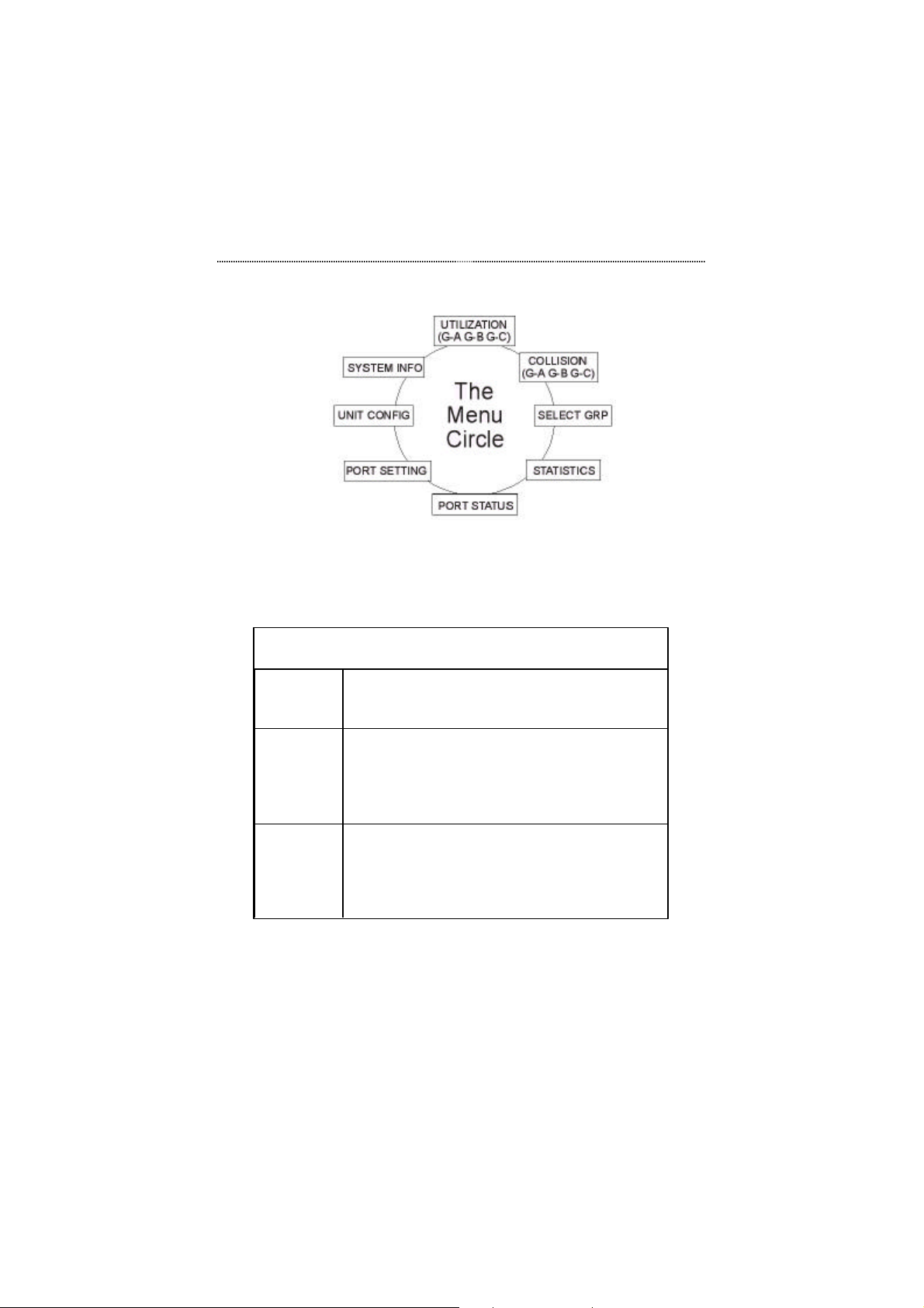
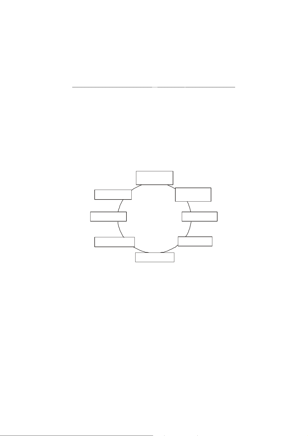
Figure 3.2 shows the Front Panel Display main menu structure. You can
scroll forward or backward through the main menu items by pressing the
Prev or Next keys. Enter menu items by pressing the Enter key.
For a detailed listing of the main menu items and all of their sub-menus,
please see the section titled Menu Tree on page 3-9 or Appendix B, Menu
Tree.
UTILIZATION
(G-A G-B G-C)
SYSTEM INFO
COLLISION
(G-A G-B G-C)
The
UNIT CONFIG
Menu
SELECT GRP
Circle
PORT SETTING
PORT STATUS
Figure 3.2 Front Panel Display Menu Circle
STATISTICS
Message Zone
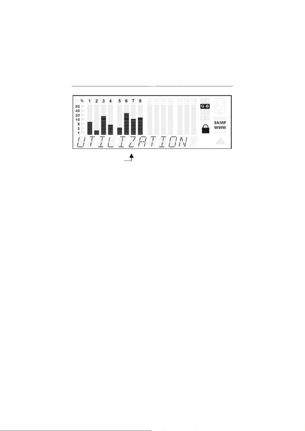
The Message Zone displays the menu items in the menu tree. Figure 3.3
illustrates the UTILIZATION menu in the message zone.
Page 32
Front Panel Display Management 3-5
Message Zone
Figure 3.3 Message Zone
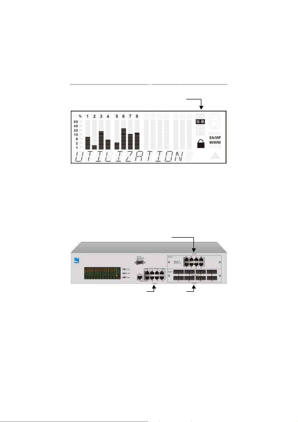
Port Group Indicators
On the right-hand side of the bar gauges, there are four port group indicators
as shown in Figure 3.4. Depending on how many optional modules you
install, there can be up to three port group indicators available: G-A (port
group A), G-B (port group B) and G- C (port group C).
The desired group can be selected in the Select Group main menu item.
Please see Select Group on page 3-15 for more information.
Note that when the Message Zone is in Collision or Utilization mode, the
Enter key can be pressed to scroll between the port groups.
Page 33
3-6 Front Panel Display Management
Port Group Indicators (Group B Selected)
Figure 3.4 Port Group Indicators
When the port group G-A icon is illuminated the Front Panel Display port
indicators 1 through 8 represent the permanent switch ports 1 through 8 as
shown in Figure 3.5. The ports of the module installed in the lower module
slot become port group B. For example, when the port group B icon is
illuminated the Front Panel Display port indicators represent the
corresponding ports of the module installed in the lower module slot. The
ports of the module installed in the upper module slot become port group C.
Port Group C
Port Group A
Figure 3.5 The Port Groups
Port Group B
Page 34
Front Panel Display Management 3-7
Observing Basic Port
Information
The basic port information, such as link up, link down, transmit/receive
activity, enabled/disabled as well as auto partition can be easily monitored
through the Port Indicators located in the first row of the Front Panel
Display.
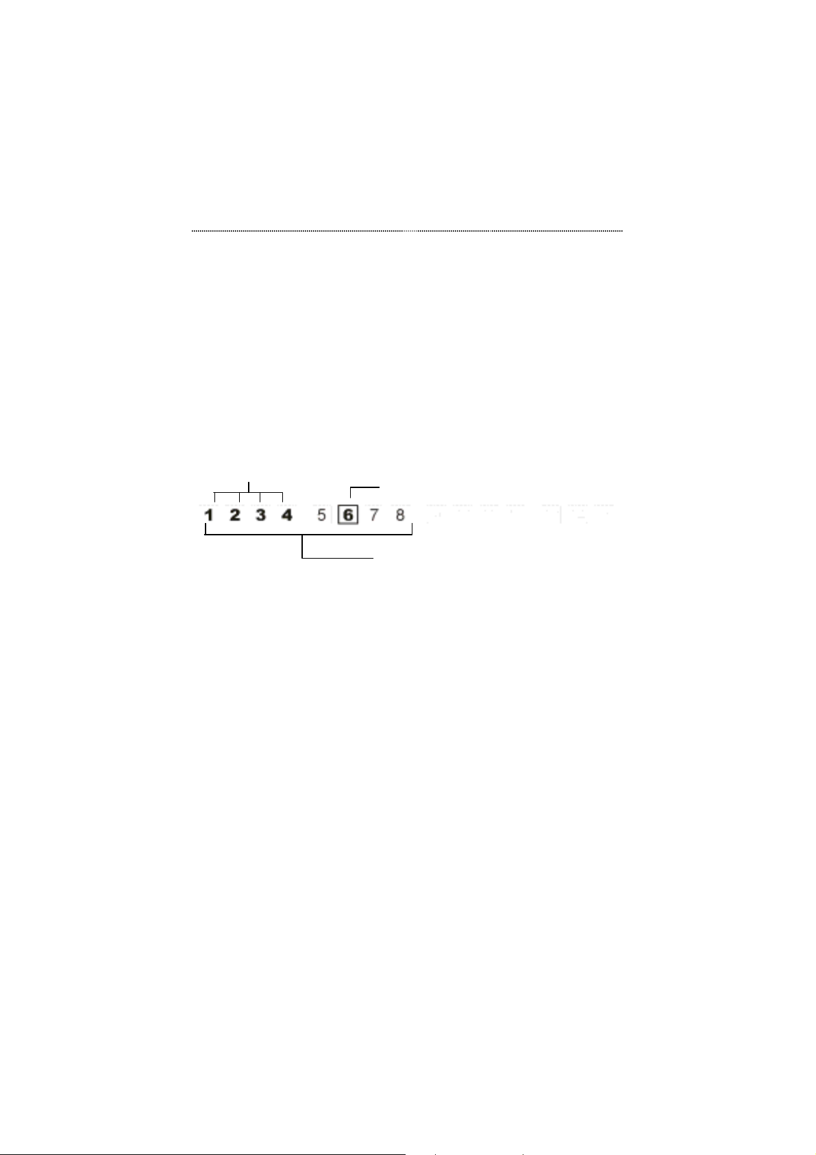
Port Available, Link Up
Figure 3.6 Port Indicators
A Port Indicator shows the activity of a given port such as link up (connected
and functioning properly), link down (not connected, but available), Tx/Rx,
enabled or disabled.
The Port Indicators show the ports that are linked up by intensifying the light
for the ports that are available. The example above shows that ports 1~4 are
linked up and port 6 is disabled.
While the ports are receiving or transmitting data, the port’s number is
flashing.
An amber frame around the port number indicates the administrator has
disabled the port.
If the frame is blinking, it means it has been partitioned automatically due to
an error condition.
Disabled by Administrator
Port Group A, B or C
Page 35
3-8 Front Panel Display Management
Port Indicator Definitions
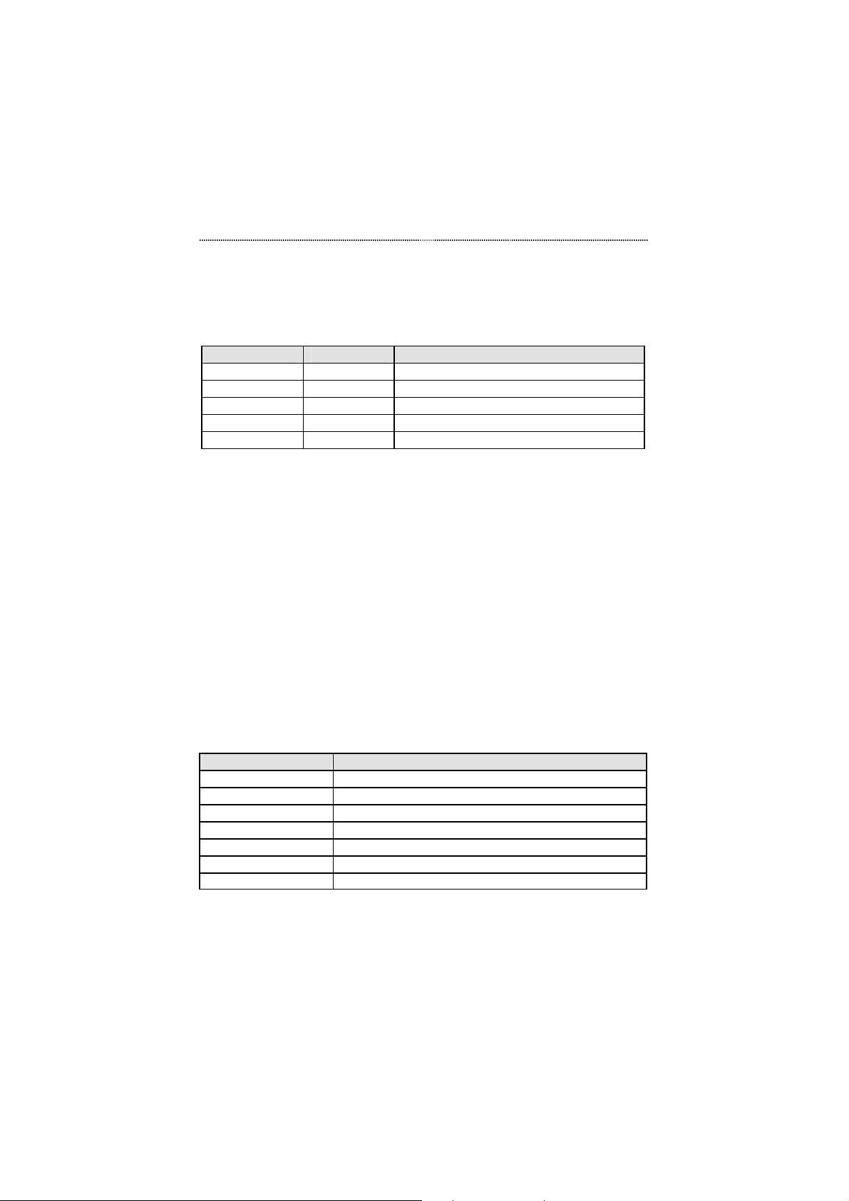
The following table summarizes the definition of the port indicators.
Port Number Frame Indicates
Dimly on Off Port enable, link down
On Off Port available, link up
Flashing Off Link up, transmitting/receiving data
On On Disabled by administrator
On Blinking Partitioned
Table 3.3 Port Indicators
Power-On Self Test
When the system power is turned on, the system automatically runs an
EEPROM TEST and a PCI TEST. This process is known as the Power-On
Self Test, or the POST. When the POST is complete, the UTILIZATION
mode will be displayed. To display other main menu items press the
Next/Prev keys.
The following table displays the messages that may be display during the
POST process.
Message Indicates
TFTP DWNLOAD Conducting TFTP download
TFTP STOP TFTP download has been stopped by user
TFTP FAILED TFTP download has failed
RT-IMG FAIL Runtime image does not exist or is invalid
LOAD RUNTIME Loading system runtime image
REBOOT System is going to reboot
WRITE FLASH Writing downloaded image to ROM
Table 3.4 POST Messages
Page 36

Front Panel Display Management 3-9
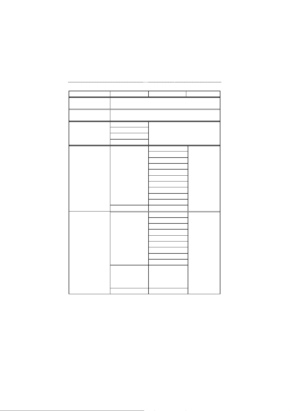
Menu Tree
There are up to four levels in the Menu Tree, main menu, sub-menu and up to
two parameter option levels. To move from a main menu item to its sub
menus, press the Enter console key while the main menu item is displayed in
the Message Zone. Press the Next or Prev key to cycle through all the items
in each menu level and press Enter to move to the next menu level or make a
selection.
Note that the Utilization and Collision menus have no sub menus.
Items appearing in the Front Panel Display with an '*' prefix are the current
configuration settings. In the following Menu Tree table, an '*' indicates
factory default configuration settings.
Page 37
3-10 Front Panel Display Management
Main Menu Sub Menu Parameter Parameter
UTILIZATION
(G-A / G-B / G-C)
COLLISION
(G-A / G-B / G-C)
SELECT GRP
STATISTICS
PORT STATUS
GROUP A
GROUP B
GROUP C
MAIN MENU
PORT 1
Through
PORT X
MAIN MENU
ALL PORTS
PORT 1
Through
PORT X
MA IN MENU
RX FRAMES
RX OCTETS
RX-ALIGN ERR
RX-PKT ERR
OVERSIZE RX
TX FRAMES
TX OCTETS
PACKET LOSS
BACK
MAIN MENU
10M PORTS
100M PORTS
1000M PORTS
HALF DUPLEX
FULL DUPLEX
ENABLED
DISABLED
BACK
MAIN MENU
(port status for
individual ports is
automatically
displayed)
Page 38
Front Panel Display Management 3-11
Main Menu Sub Menu Parameter Parameter
PORT SETTING
UNIT CONFIG
SYSTEM INFO H/W VER,
PORT 1
Through
PORT X
MAIN MENU
LOOP DETECT
CONSOLE
LOCK
NETWORK
CONF
SET PASSWORD
SYS RESTART
SYS DEFAULT
MAIN MENU
S/W VER,
IP ADDRESS,
SUBNET MASK,
DEFAULT GATEWAY
10BASE-T
100BASE-X
1000BASE-SX
*AUTO-NEGO
HALF DUPLEX
FULL DUPLEX
*ENABLED
DISABLED
BACK
MAIN MENU
ENABLED
*DISABLED
BACK
MAIN MENU
ENABLED
DISABLED
BACK
MAIN MENU
IP ADDRESS
SUBNET MASK
DEF GATEWAY
BACK
MAIN MENU
Note: You must enter the four digit password to enter the PORT SETTING
and UNIT CONFIG menus. The default password is "0000".
Page 39

3-12 Front Panel Display Management
Exiting the Menu Tree
To exit a sub-menu, cycle through each menu option until a “MAIN MENU”
or “BACK” is displayed in the Message Zone. Press the Enter key to return
to the Main Menu or previous menu level.
Utilization
Monitoring the traffic load is accomplished by simply selecting a port group
and then UTILIZATION from the main menu. While UTILIZATION is
displayed in the message zone the level of utilization for the enabled ports of
this port group is indicated by the bar gauges moving up and down as the
traffic load varies.
The reference for the level of utilization is based on the speed of the port that
is running. For example, a port that is running in 10Mbps half duplex, the
100% stands for the bandwidth of 10M. The following table shows the
relation for each speed:
SPEED 100% Stands for:
10M half duplex 10M
10M full duplex 20M
100M half duplex 100M
100M full duplex 200M
1000M half duplex 1000M
1000M full duplex 2000M
Table 3.5 Utilization Ratio
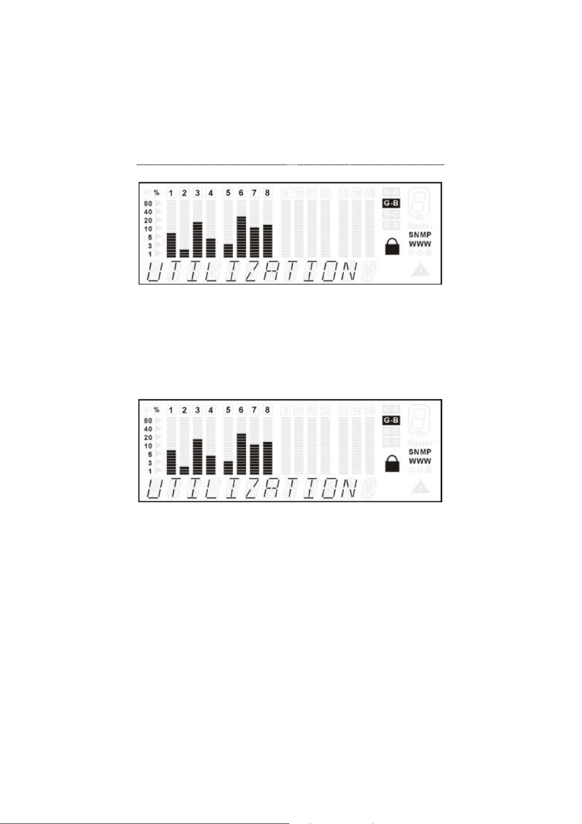
The UTILIZATION menu displays the utilization of all ports, and the port
number indicators indicate the port numbers.
Page 40
Front Panel Display Management 3-13
Figure 3.7 Utilization for Group A Ports
Press Enter to switch between the port groups. The port group indicators
on the right hand side of the Front Panel Display indicate the port
group that you select to view.
Figure 3.7 and Figure 3.8 illustrate the utilization of port group A and port
group B respectively.
Figure 3.8 Utilization for Group B Ports
The port number indicator and frame indicate the status of the ports in real
time. The definitions for the port number indicator and frame are summarized
as follows:
Page 41
3-14 Front Panel Display Management
Port
Number
Dimly on Off Port enable, link down
On Off Port available, link up
Flashing Off Link up, transmitting/receiving data
On On Disabled by administrator
On Blinking Partitioned
Frame Indicates
Table 3.6 Port Indicators
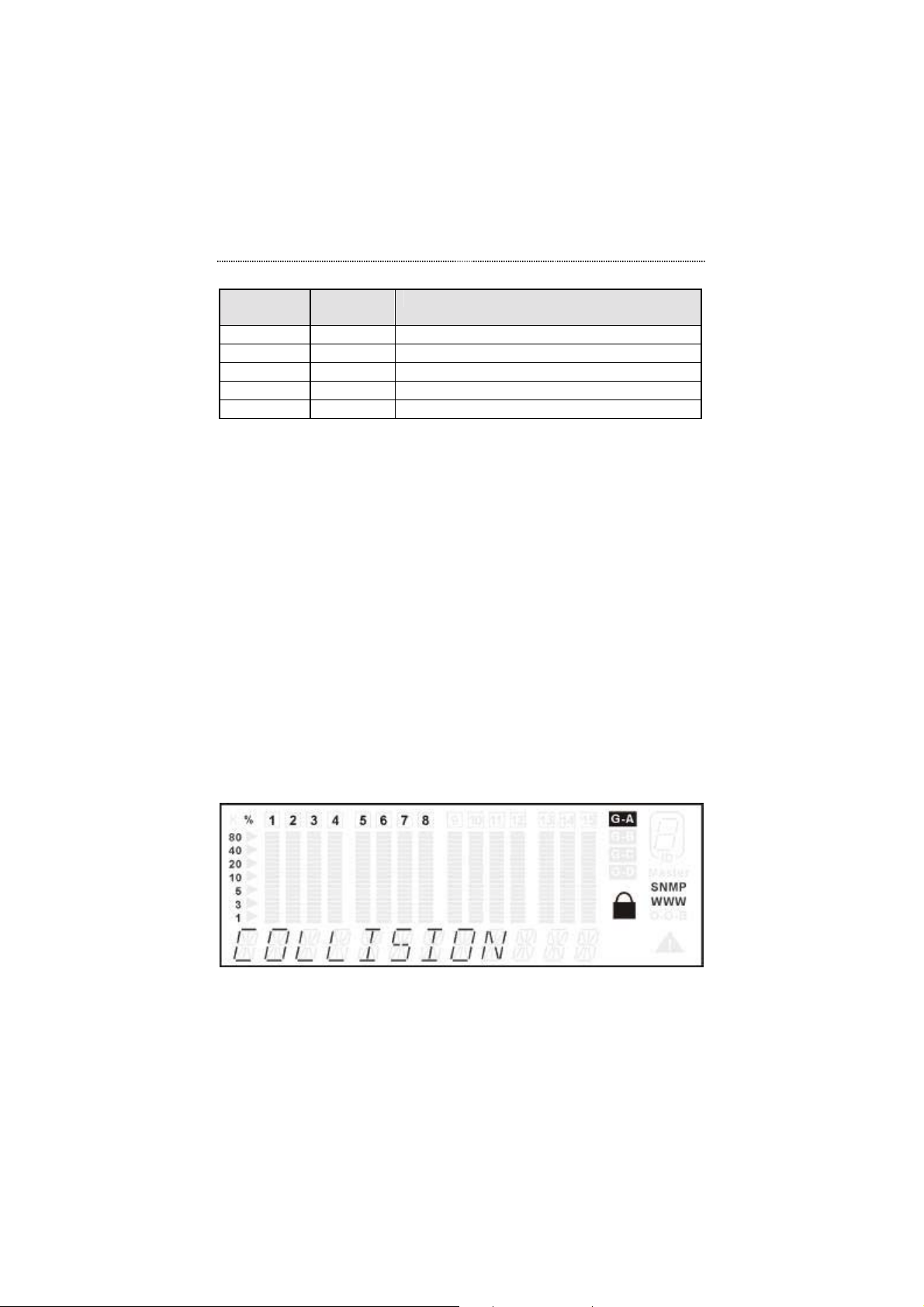
Collision
When COLLISION is the menu item in the Message Zone, the Port Number
will be illuminated for each port that is connected and the bar gauges
continuously move up or down indicating the percentage of Collision for
these ports. A collision occurs when a port, in half-duplex mode, attempts to
send and receive packets at the same time. The Collision percent can be
calculated with the following formula.
Collision Ratio = (number of packets collided / number of packets
transmitted) * 100.
Press Next in the MAIN MENU to sele ct COLLISION.
Figure 3.9 Collision Menu
Page 42
Front Panel Display Management 3-15
Select Group
There are three possible groups in the Switch, group A, B, and C. The 8 builtin ports are represented by group A. Groups B and C represent the optional
modules' ports. When no modules are installed on the switch, there is only
one group (group A).
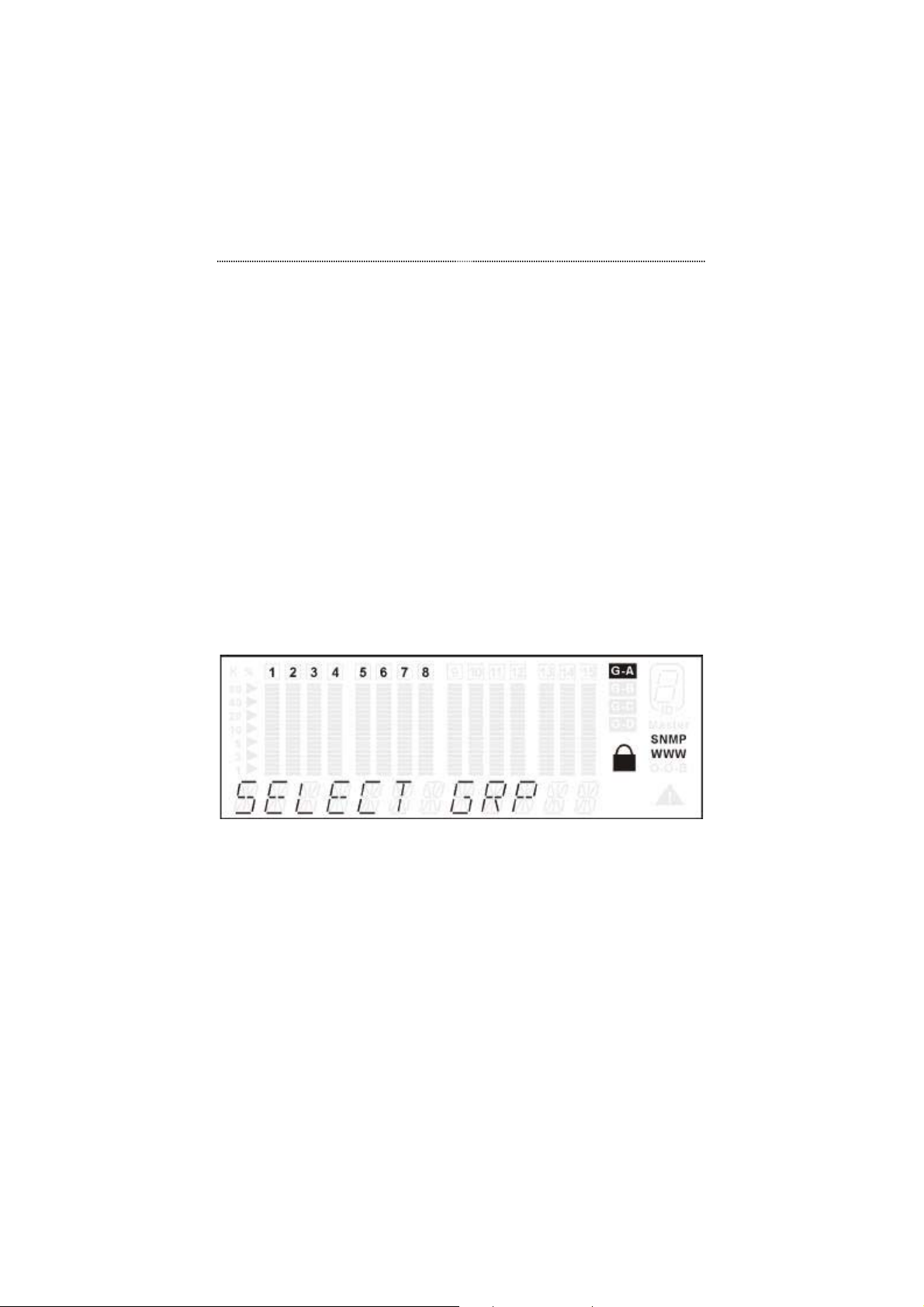
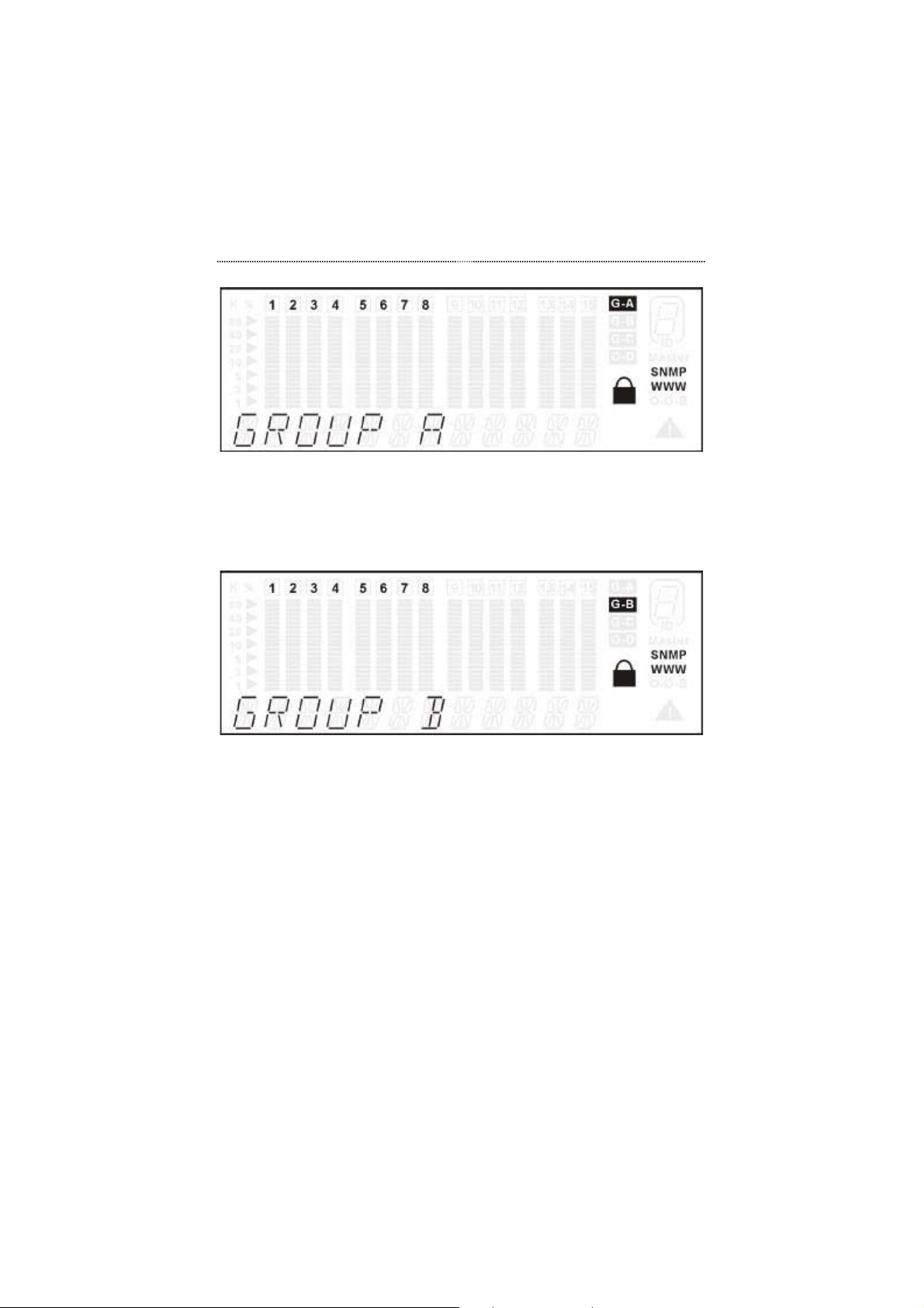
The SELECT GRP menu as shown in Figure 3.10 allows users to select the
port group (A, B, or C) for monitoring the statistics counters and port status,
and for configuring the ports in the group.
Press Next in the MAIN MENU to select SELECT GRP.
Figure 3.10 Select Group Menu
Press Enter to enter the port group selection menu. The currently selected
port group will be displayed on the Front Panel Display as shown in
Figure 3.11.
Page 43
3-16 Front Panel Display Management
Figure 3.11 Select Port Group A
Press Prev and Next to scroll the port groups back and forth.
Press Enter to make a selection as shown in Figure 3.12.
Figure 3.12 Select Port Group B
Statistics
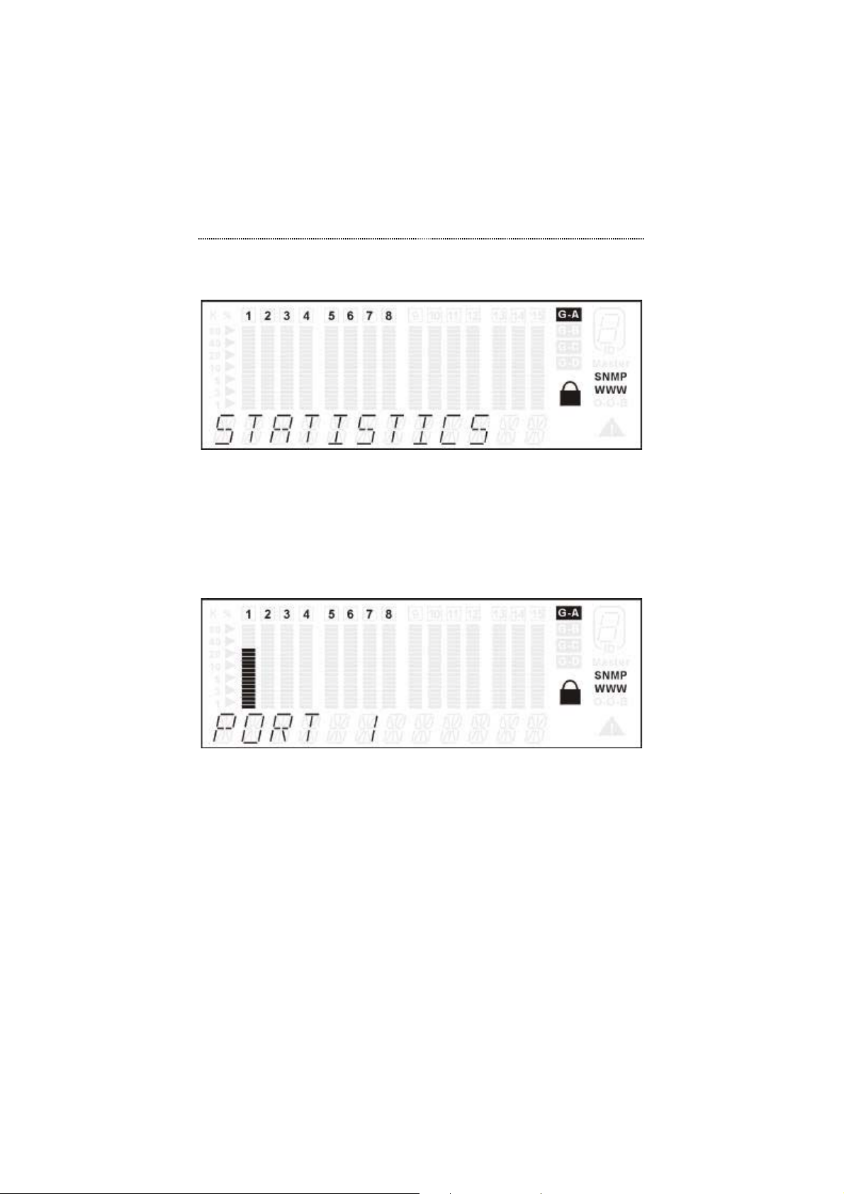
The STATISTICS menu displays the statistic counters of ports. It may be
helpful to look at the counters to isolate network problems. All the counters
display the accumulated value from the time the switch was powered on.
The statistics menu is shown in Figure 3.13.
Page 44
Front Panel Display Management 3-17
Press Next in the MAIN MENU to select STATISTICS.
Figure 3.13 Statistics Main Menu
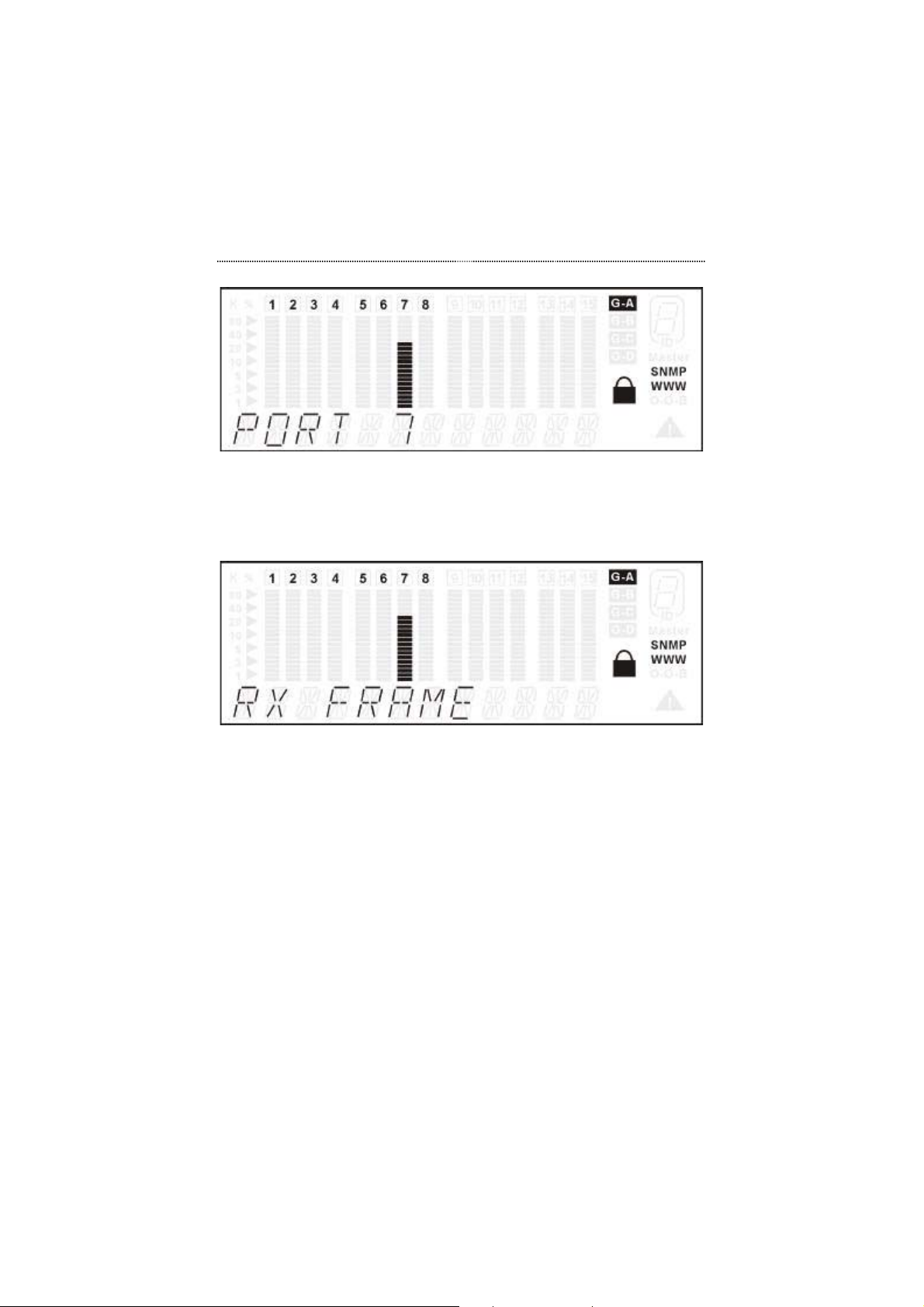
Press Enter to go to the port selection menu. The port selection menu
allows users to select a port in the current port group for monitoring
statistics counters. In the port selection menu, the selected port is
indicated by a lighted bar gauge under the port number and the port
number is indicated in the message zone as shown in Figure 3.14.
Figure 3.14 Port Selection Menu
Press Prev or Next to select the desired port within the given port group
as shown in Figure 3.15.
Page 45
3-18 Front Panel Display Management
Figure 3.15 Selecting Port 7 in Group A
Press Enter to make a port selection. The counter selection menu will
then be displayed as shown in Figure 3.16.
Figure 3.16 Counter Selection Menu
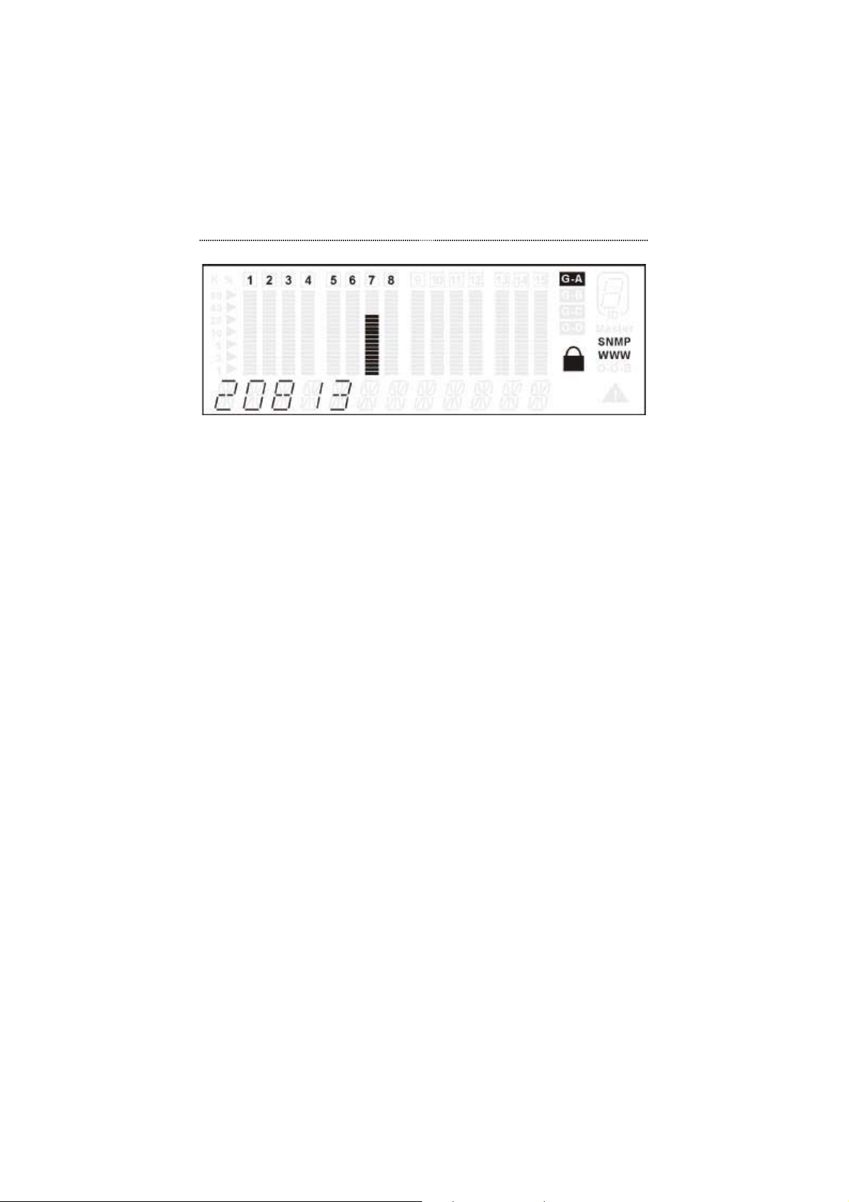
Press Prev and Next to scroll back and forth through the statistics counter
options.
Press Enter to make a selection. The counter value will be displayed as
shown in the Figure 3.17 example.
Page 46
Front Panel Display Management 3-19
Figure 3.17 Readable Frames Counter
Statistics Counters
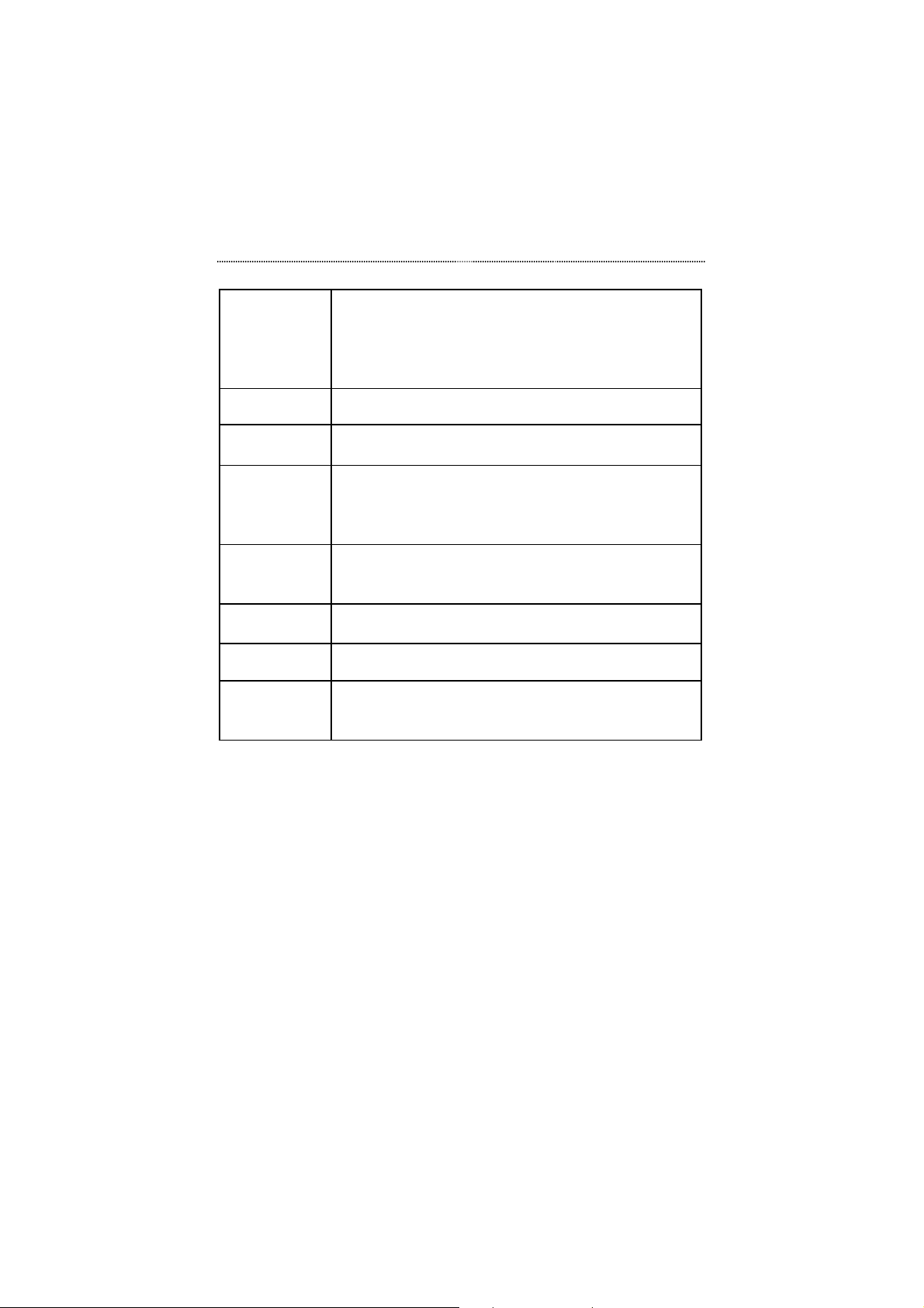
The available statistics counters are listed in Table 3.7.
Page 47
3-20 Front Panel Display Management
RX FRAMES Displays the total number of good packets received
including:
Unicast packets
Broadcast packets
Multicast packets
RX OCTETS To display the count of data and padding octets in frames
that were successfully received.
RX--ALIGN
Displays the number of alignment errors.
ERR
RX--PKT
ERR
Displays Packets received with any of the following
errors:
The packet contains a CRC error
The packet is a runt (undersized)
OVERSIZERXDisplays the number of packets received that were
longer than 1532 octets and were otherwise well
formed.
TX FRAMES Displays the number of packets transmitted
successfully.
TX OCTETS To display the count of data and padding octets of frames
that were successfully transmitted for the selected port.
PACKET
LOSS
Displays the number of error free packets received
by this port that were dropped due to a full transmit
buffer or oversized packets.
Table 3.7 Port Statistics Counters
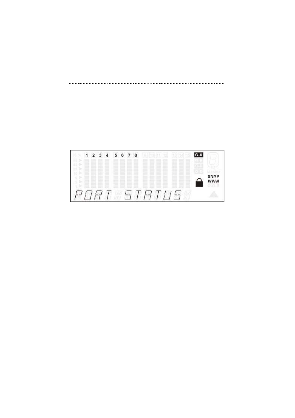
Port Status
The PORT STATUS menu allows you to view port settings. When
monitoring individual ports, the settings are automatically scrolled through
the Message Zone and the bar scales under the port number are illuminated.
When monitoring All Ports, the status is not auto cycled, you must press the
Next key to view each parameter. The bar scales under the port numbers that
Page 48
Front Panel Display Management 3-21
are displayed higher indicate the port is configured to the setting displayed in
the message Zone. The shorter bar scales under the port numbers indicate the
port is not set to the setting displayed in the message zone.
All ports can be running at the same or different settings. It is useful to check
the port setting to see if it has been running in the desired mode.
Press Next in the MAIN MENU to select the PORT STATUS menu as
shown in Figure 3.18.
Figure 3.18 Port Status Menu
Press Enter to go to the port selection menu. The port selection menu
allows users to select “all ports” or “a single port” for monitoring
the port status.
Press Prev and Next to scroll the menu options back and forth.
Press Enter to make a selection. The information will be displayed
automatically.
Status Indicators
The following is a list of the port status indicators:
• 10M PORTS
• 100M PORTS
• 1000M PORTS
• HALF DUPLEX
• FULL DUPLEX
• ENABLED
Page 49
3-22 Front Panel Display Management
• DISABLED
All Ports Status
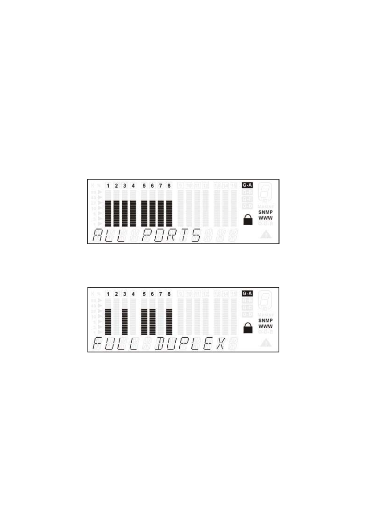
Press Next to select ALL PORTS in the port selection menu as shown in
Figure 3.19.
Figure 3.19 Selecting All Ports
Press Enter to view the status for all ports as shown in the example in
Figure 3.20.
Figure 3.20 Full Duplex Ports
Page 50
Front Panel Display Management 3-23
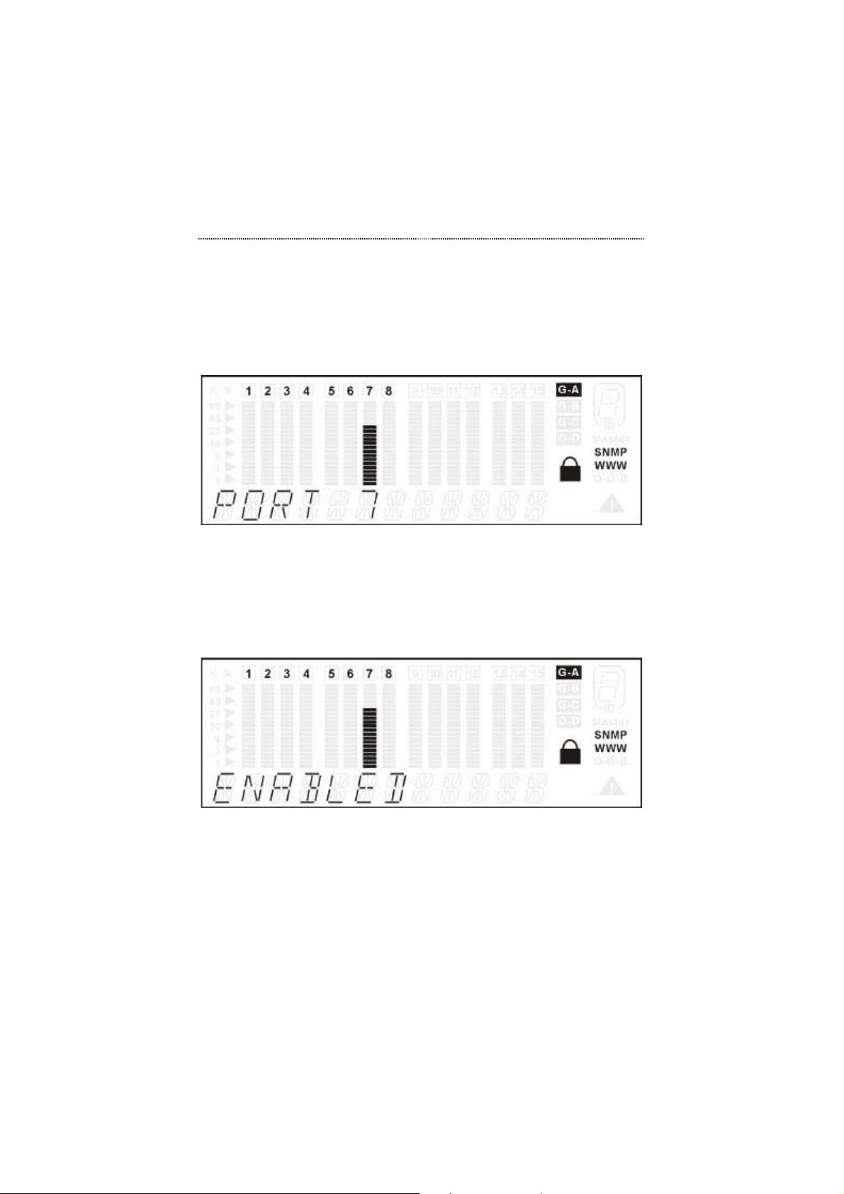
Single Port Status
Press Next to select a single port in the port selection menu as shown in
Figure 3.21.
Figure 3.21 Selecting Port 7
Press Enter to view the status for the port as shown in the example in
Figure 3.22. The six-level bar indicates the port number you select,
the port status applied to this port will be displayed in the message
zone.
Figure 3.22 The Status Of Port 7
Page 51

3-24 Front Panel Display Management
Port Setting
The PORT SETTING menu is used to configure individual ports. This
section will explore several aspects concerning the port setting menu.
Auto-Negotiation
All Switch ports support auto-negotiation. Auto-negotiation is the default
setting for all ports.
In auto-negotiation mode, the switch learns the settings of the link partner
and configures itself to the highest possible transfer rate settings provided
that the link partner also supports auto-negotiation.
In some conditions you should set the connection mode manually, such as
when the link partner does not support auto-negotiation. Please see the
section titled "Configuring Port Settings" on page 3-25 for port setting
information.
Note that if the link partner does not support auto-negotiation, the Switch
may be left in AUTO-NEGO mode. In this situation, the Switch will still be
able to detect the correct speed, but will default to half-duplex mode. It is
therefore recommended that in this situation, the connection mode be set
manually.
While AUTO-NEGO is set, the speed and duplex selections are no longer
available. The speed and duplex will be decided by the result of the
negotiation with the link partner. By contrast, if either the speed or duplex is
selected, the AUTO-NEGO function will not work. It forces the port to run in
the set mode.
Setting the port speed forces the port to use the selected speed only, if the
device being contacted is set at a different speed, the data will not be sent.
When a setting is selected, an asterisk symbol (‘*’) will be added to the first
character of the string. This makes it convenient to check what the settings
for these ports are. These settings can be viewed through the PORT
Page 52
Front Panel Display Management 3-25
SETTING menu. When you see an item that begins with an ‘*’, the port is set
in that mode.
All settings will be saved in the EEPROM.
Port Setting Options
Users may perform the following port settings:
• 10BASE-T
• 100BASE-X
• 1000BASE-SX
• AU TO-NEGO
• HALF DUPLEX
• FULL DUPLEX
• ENABLED
• DISABLED
Configuring Port Settings
The following will explain how to configure individual port settings.
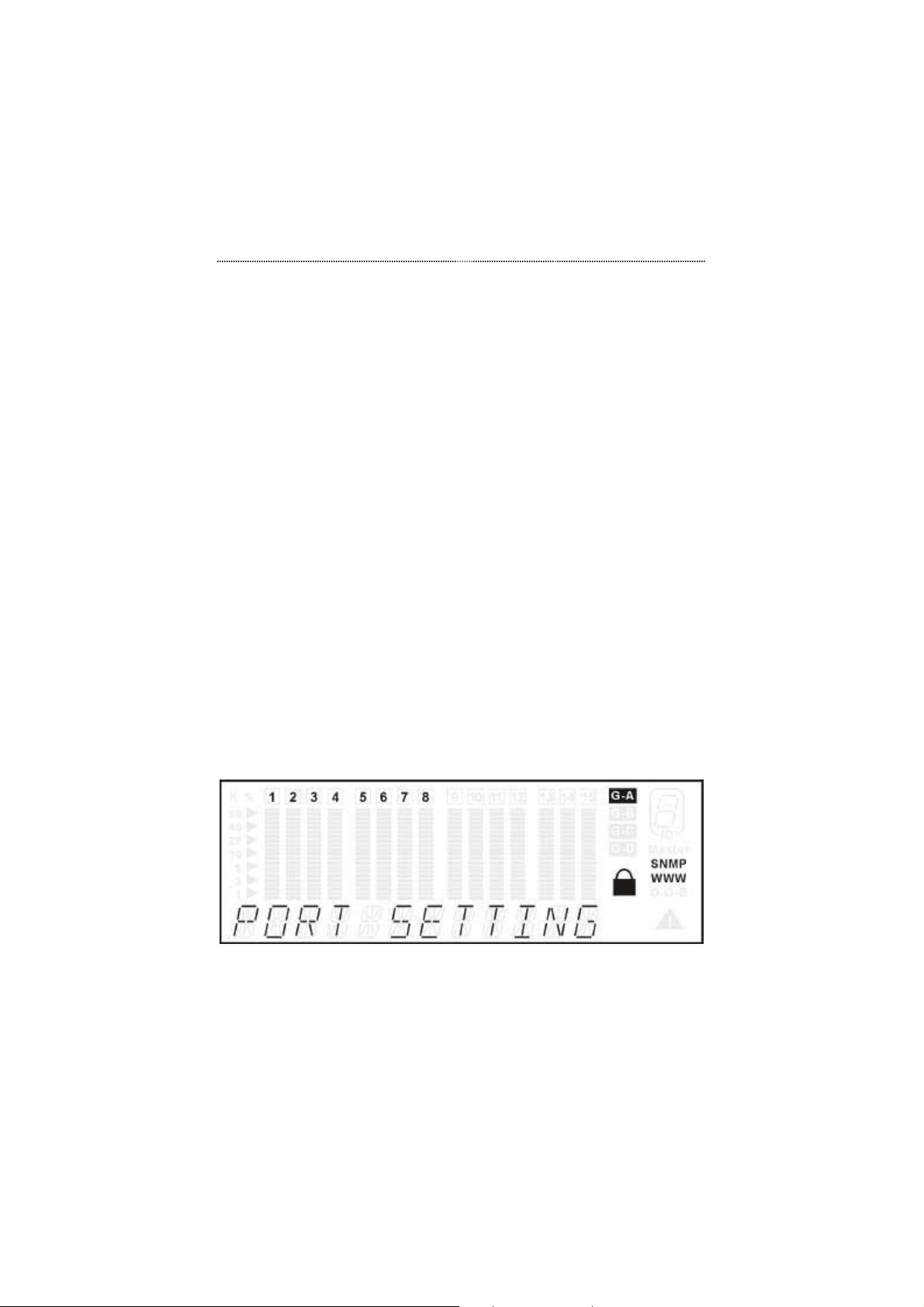
Press Prev or Next in the MAIN MENU to select PORT SETTING.
Figure 3.23 Port Settings Menu
Page 53
3-26 Front Panel Display Management
User Authentication
To configure a port, user authentication is required when the system is locked.
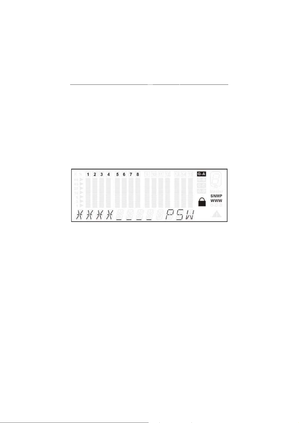
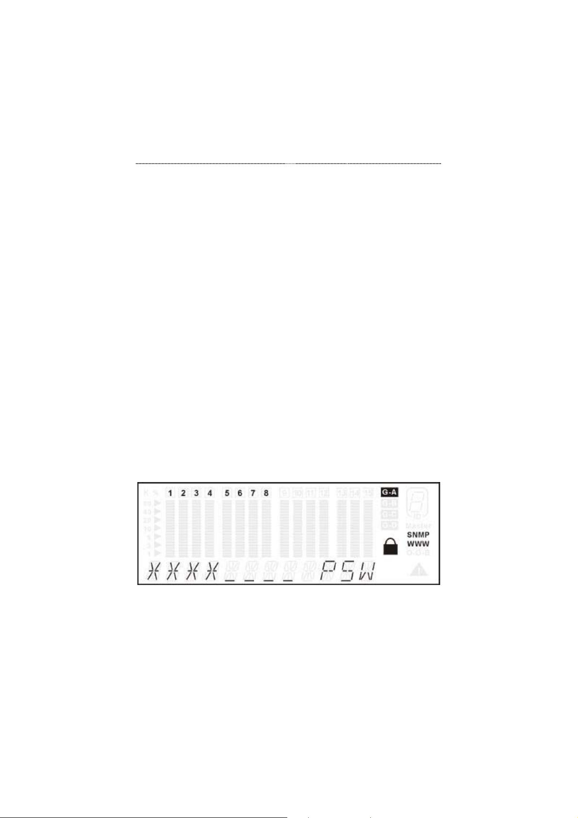
The user will be prompted to enter the password. The password is composed
of four numeric digits represented by the four asterisks as shown in Figure
3.24.
The factory default password is "0000".
Press Enter. You will briefly see the SYS LOCKED message, then the
password request.
Figure 3.24 Password Verification
Press Prev once to select the first digit.
Press Next to select next asterisk.
Press Prev to select the next digit. Repeat to enter the password.
Press Enter. You will briefly see the PASSED message if the password is
correct and the system will be unlocked. If the password is incorrect,
FAIL will be displayed, and the user will have to re-enter the
password.
Selecting a Port
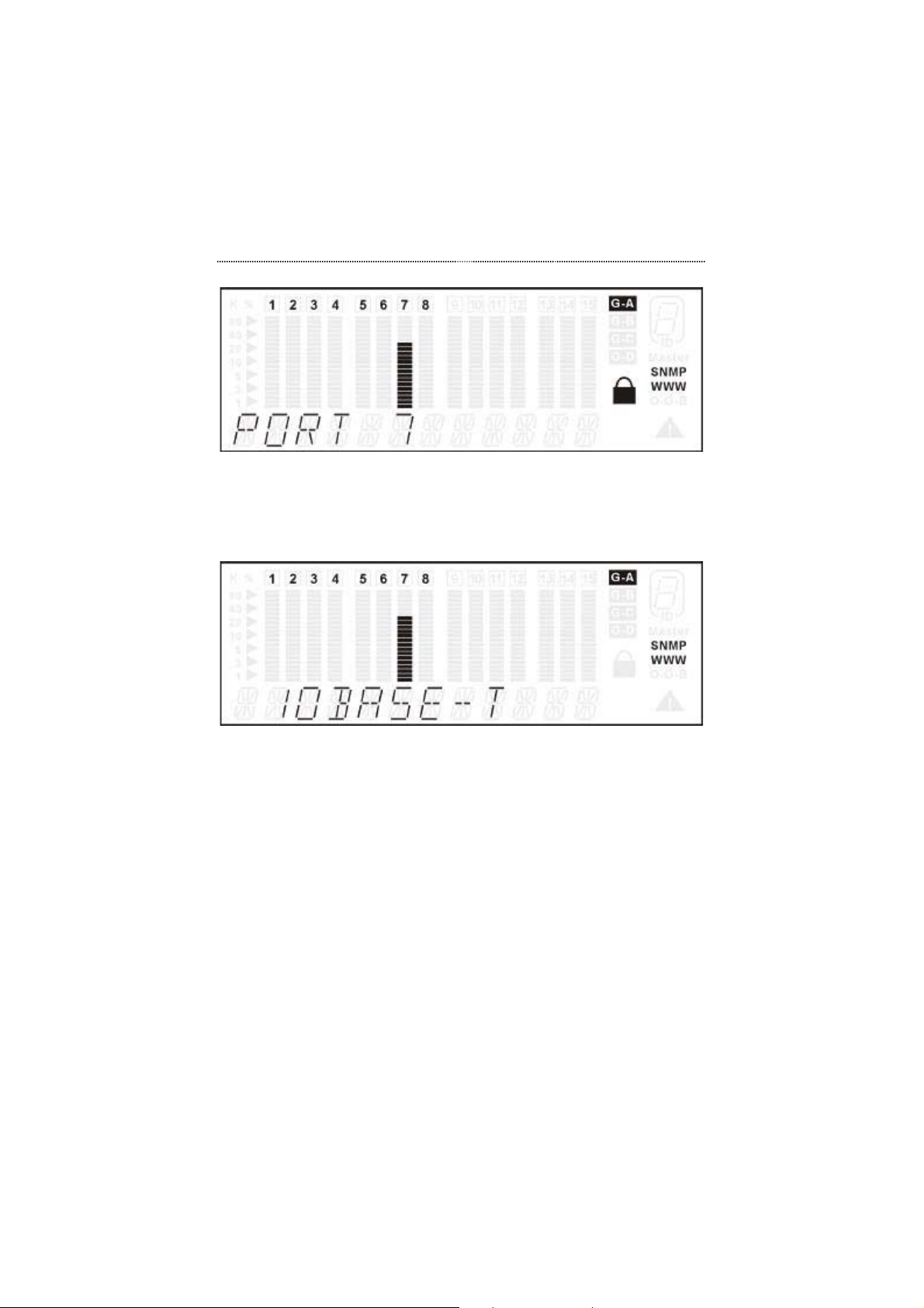
Press Prev or Next to select a port as show in the example in Figure 3.25.
Page 54
Front Panel Display Management 3-27
Figure 3.25 Selecting Port 7
Press Enter to view the setting options as shown in the example in Figure
3.26.
Figure 3.26 Configuring a Port -- Before Setting
Press Prev or Next to scroll through the setting options.
Press Enter once the desired setting is found to apply the configuration to
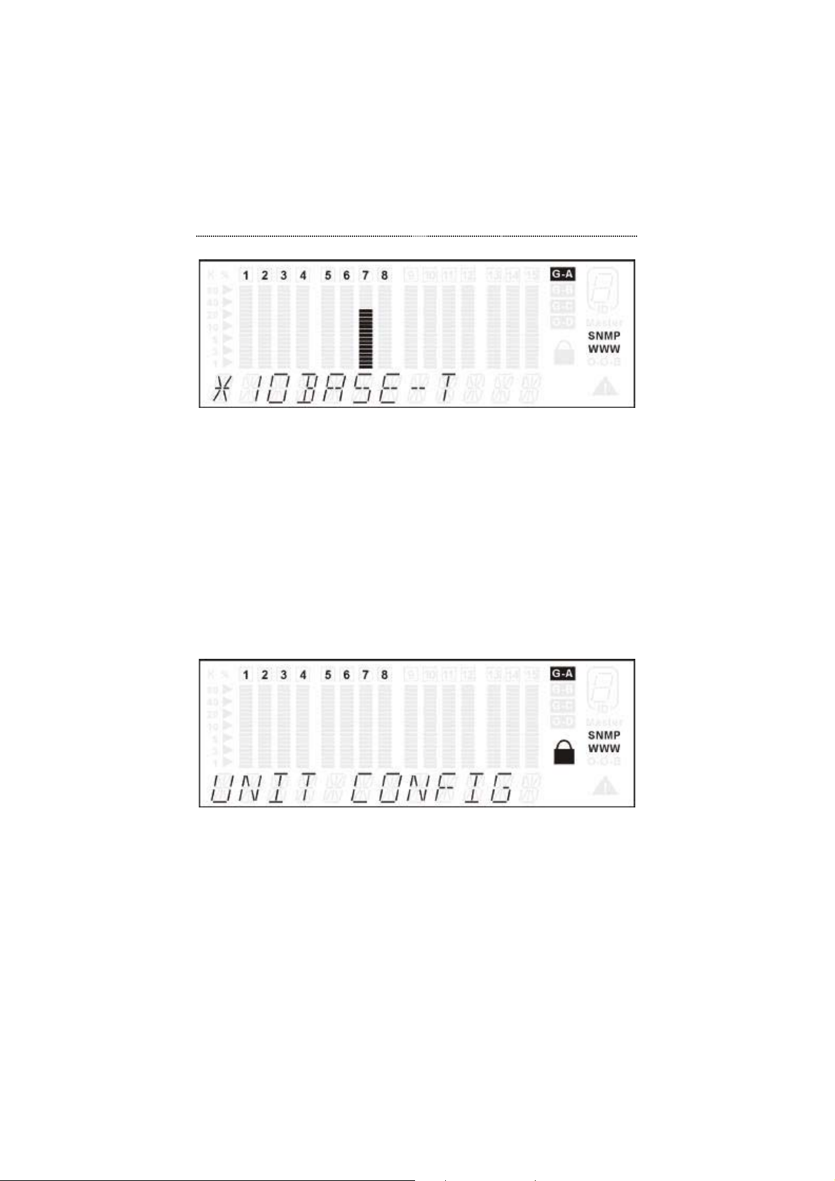
the port as shown in Figure 3.27. An asterisk sign indicates the port
configuration when displayed in the message zone.
Page 55
3-28 Front Panel Display Management
Figure 3.27 Configuring a Port -- After Setting
Unit Configuration
The UNIT CONFIG menu shown in Figure 3.28 allows users to configure the
switch as a whole.
Press Prev or Next in the MAIN MENU to select UNIT CONFIG.
Figure 3.28 Unit Configuration Main Menu
To configure the switch, user authentication is required. Please refer to the
section titled "User Authentication" on page 3-26 if you need information on
how to enter the password.
Page 56
Front Panel Display Management 3-29
Unit Configuration Options
Users may perform the following configurations to the device:
• LOOP DETECT
• CONSOLE LOCK
• NETWORK CONFIGURATION
• IP ADDRESS
• SUBNET MASK
• DEFAULT GATEWAY
• SET PASSWORD
• SYSTEM RESTART
• SYSTEM DEFAULT (i.e. Factory Reset)
User Authentication
To enter the Unit Configuration menu, user authentication is required when
the system is locked. The user will be prompted to enter the password. The
password is composed of four numeric digits represented by the four
asterisks as shown in Figure 3.29. The factory default password is "0000".
Press Enter. In the UNIT CONF menu You will briefly see the SYS
LOCKED message, then the password request.
Figure 3.29 Password Verification
Press Prev to select the first digit.
Page 57
3-30 Front Panel Display Management
Press Next to select next asterisk.
Press Prev to select the next digit. Repeat to enter the password.
Press Enter. You will briefly see the PASSED message if the password is
correct and the system will be unlocked. If the password is incorrect,
FAIL will be displayed, and the user will have to re-enter the
password.
Loop Detect
Loop Detect is an important feature of the Switch. A loop is created if two
ports are inadvertently connected to each other. If a loop is detected, a
message indicating so will be sent to the Console Management menu
Spanning Tree Protocol (STP) Port Configuration. Please see the section
titled Device Control in Chapter 5, Console Management. A message will
also be sent to the same menu in the Web Management interface.
A switching device can not sustain a loop because it produces a broadcast
storm thereby jamming the system with looping packets. The Switch supports
looped port detection. If the function is enabled, the Switch will search for
looped ports when the Port Status is being checked.
Loop Detect is disabled at the time the switch is shipped from manufacturer.
You have to enable the function through the Front Panel Display. The
command sequence is:
UNIT CONFIG > LOOP DETECT > ENABLE><Enter>
After the command is entered, it will be saved in the EEPROM.
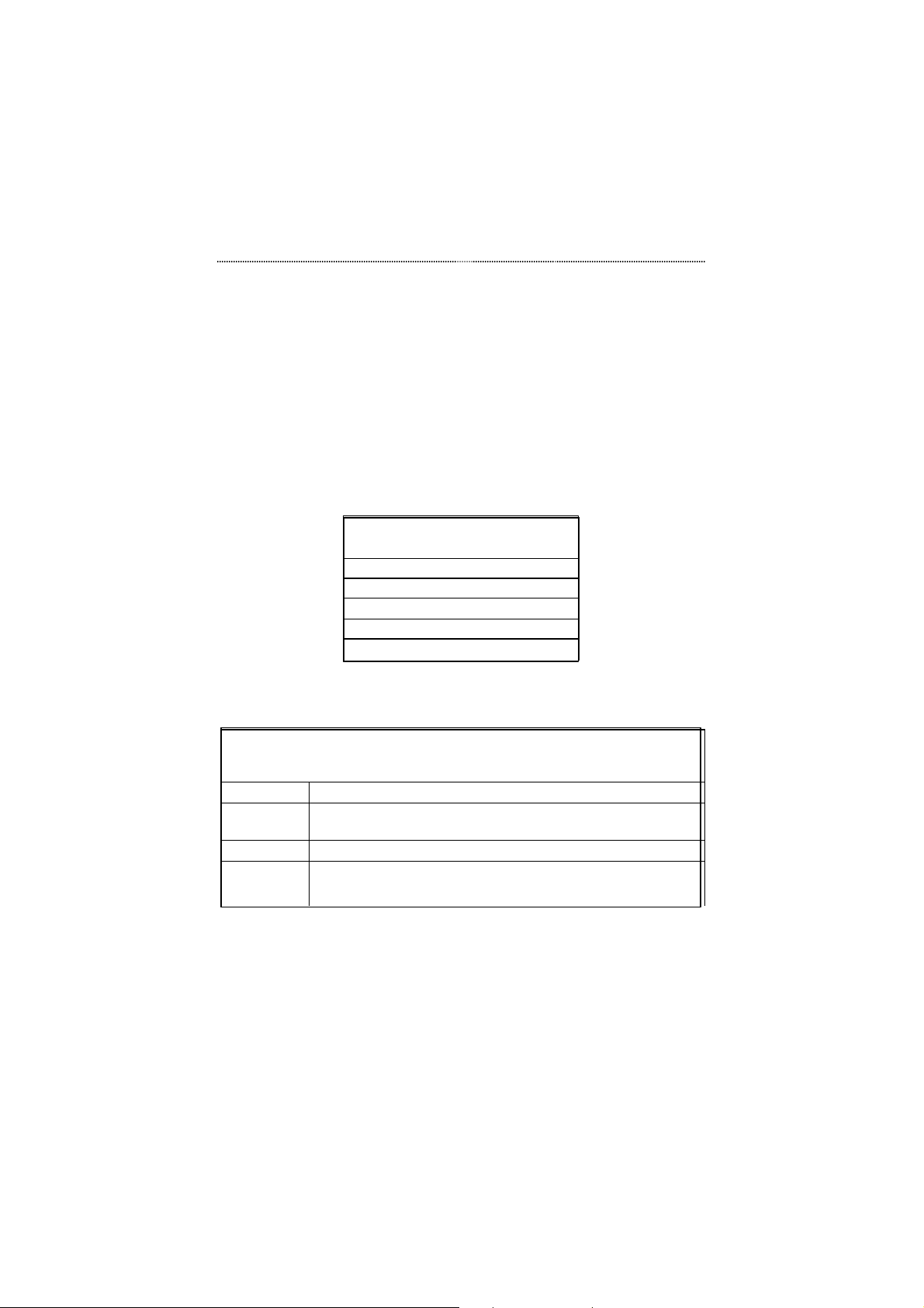
Sub-Menu Command Press to set:
Loop Detect Enable Enter
Disable Enter
Back Enter
Table 3.8 Loop Detect
Page 58
Front Panel Display Management 3-31
Console Lock
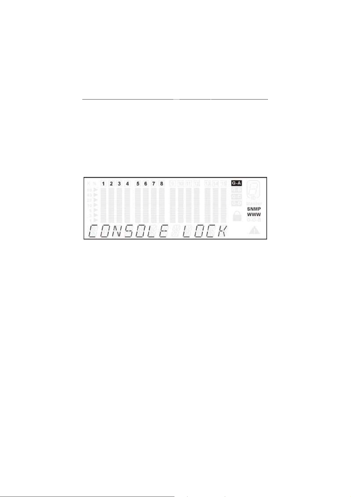
Th e CONSOLE LOCK menu shown in Figure 3.30 allows users enable or
disable the Front Panel Display configuration lock.
Press Prev or Next in the UNIT CONFIG MENU to select CONSOLE
LOCK.
Figure 3.30 Console Lock Menu
The Console Lock prevents unauthorized persons from making configuration
settings to the Switch. Once the console is locked, a password is required to
enter the PORT SETTING or UNIT CONFIG menus.
The lock sign on the Front Panel Display is ON when the console is locked
and OFF when the console is unlocked.
The Switch is shipped with the password "0000".
Lock the Console
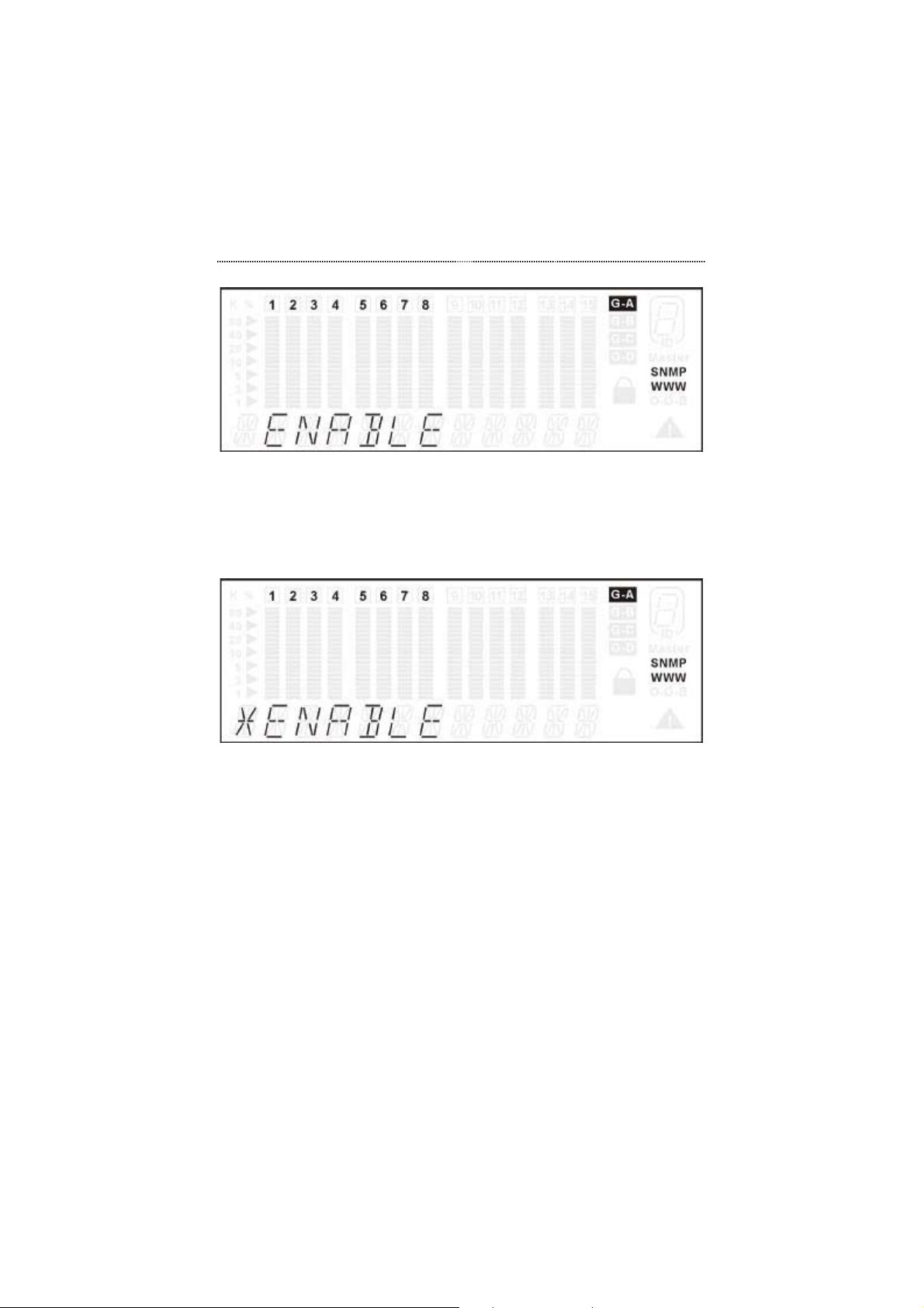
Press Prev or Next to select the ENABLE menu item as shown in Figure
3.31.
Page 59
3-32 Front Panel Display Management
Figure 3.31 Set Console Lock (before setting)
Press Enter to enable the lock. When the device is locked, a lock sign and
an asterisk will be displayed on the Front Panel Display as shown in
Figure 3.32.
Figure 3.32 Set Console Lock (after setting)
Press Next to select BACK or MAIN MENU.
Unlock the Console
Press Prev or Next to select DISABLE in the CONSOLE LOCK menu.
Press Enter. An asterisk will be displayed on the left and the lock icon
will be open to indicate that the Front Panel Display is unlocked.
Press Next to select BACK or MAIN MENU.
Page 60
Front Panel Display Management 3-33
Network Configuration
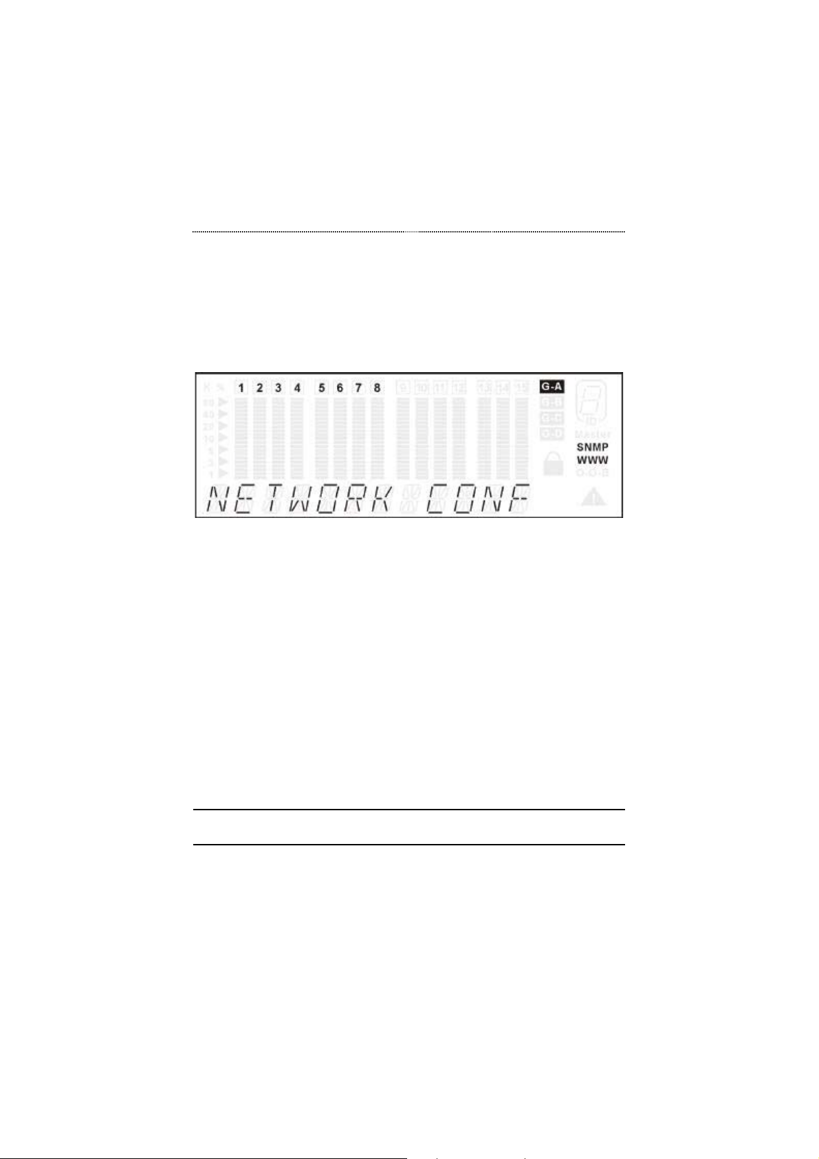
The NETWORK CONF menu, as shown in Figure 3.33, contains the three
parameters that allow you to configure the Switch on your network.
Figure 3.33 Network Configuration Menu
Network Configuration Options
Users may perform the following Network Configuration options:
• IP ADDRESS
• SUBNET MASK
• DEFAULT GATEWAY
Configuring the Parameters
The following will explain how to configure the Network Configuration
parameters.
Note that the Switch must be rebooted before changes in these setting are
configured on the network.
Page 61
3-34 Front Panel Display Management
IP Address
Press Prev or Next in the NETWORK CONF menu to select IP
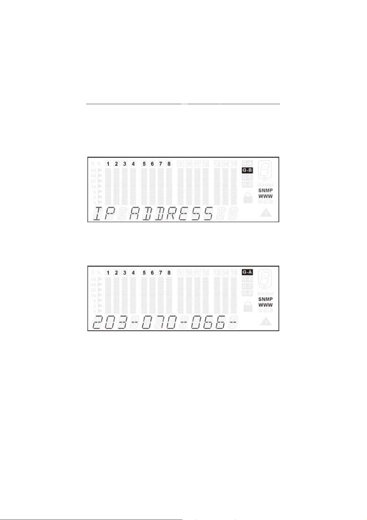
ADDRESS as shown in the example in Figure 3.34.
Figure 3.34 Selecting IP ADDRESS
Press Enter. You will now see the IP ADDRESS menu as shown in
Figure 3.35. The current IP address will be displayed.
Figure 3.35 Setting the IP Address
Press Prev to select the first desired digit.
Press Next to select next digit. Repeat to enter the Switch IP address.
Press Enter. You will briefly see the OK message. The IP ADDRESS
message will then be displayed again.
Press Next to select BACK.
Press Enter. You will see NETWORK CONF.
Page 62

Front Panel Display Management 3-35
Press Next to select SYS RESTART.
Press Enter. You will see SYS REBOOT.
Press Enter to restart the Switch. The reboot will take several moments.
The Switch is now configured in your network.
Subnet Mask
Setting the Subnet Mask involves the same process as setting the IP address.
Please refer to IP Address on page 3-34 for guidance on setting the Subnet
Mask.
Default Gateway
Setting the Default Gateway involves the same process as setting the IP
address. Please refer to IP Address on page 3-34 for guidance on setting the
Default Gateway.
Set Password
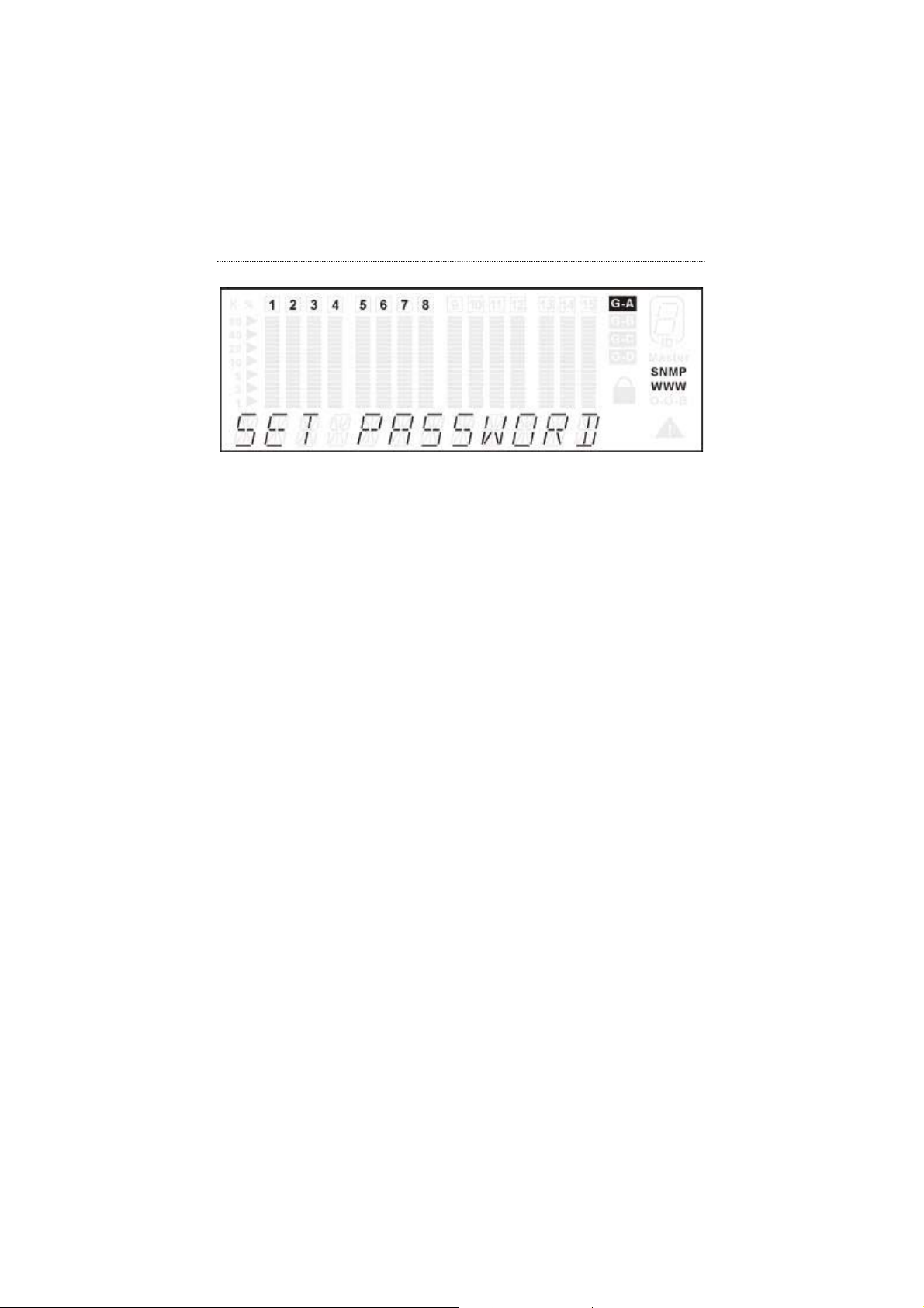
The SET PASSWORD menu as shown in Figure 3.36, allows users to set up
the password. The password consists of four numeric digits (“0”-“9”). The
Switch is shipped with the password "0000".
Press Prev or Next in UNIT CONFIG to select SET PASSWORD.
Page 63
3-36 Front Panel Display Management
Figure 3.36 Set Password Menu
Press Enter. You will see the SET PASSWORD menu as s hown in
Figure 3.36.
Press Prev once to select the first digit.
Press Next to select next asterisk.
Press Prev to select the next digit. Repeat to enter the new password.
Press Enter. You will briefly see the OK message. The new Front Panel
Display password will take effect immediately, so be sure to write it
down.
System Restart
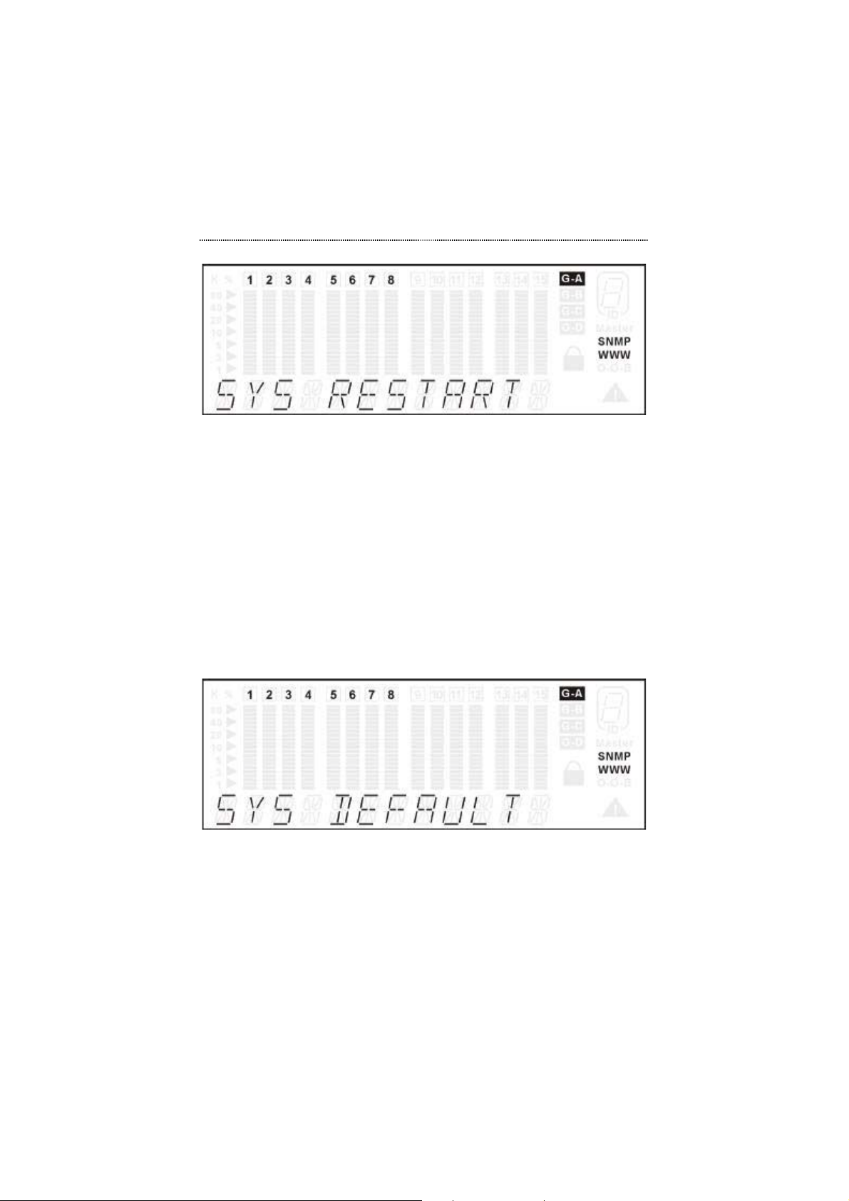
The system restart menu as shown in Figure 3.37 allows users to perform a
warm restart.
Press Prev or Next in UNIT CONFIG to select SYS RESTART.
Page 64
Front Panel Display Management 3-37
Figure 3.37 System Restart Menu
Press Enter in the SYS RESTART menu to perform a warm restart. You
will see SYS REBOOT in the message zone for a few moments
while the Switch is rebooting.
System Default
The system default menu shown in Figure 3.38, allows users to reset the
device to the original factory configuration.
Press Prev or Next in UNIT CONFIG to select SYS DEFAULT.
Figure 3.38 System Default Menu
Press Enter in the SYS DEFAULT menu to perform the factory reset.
The Switch will then automatically restart, with all settings
reverting to the factory defaults.
Page 65
3-38 Front Panel Display Management
System Information
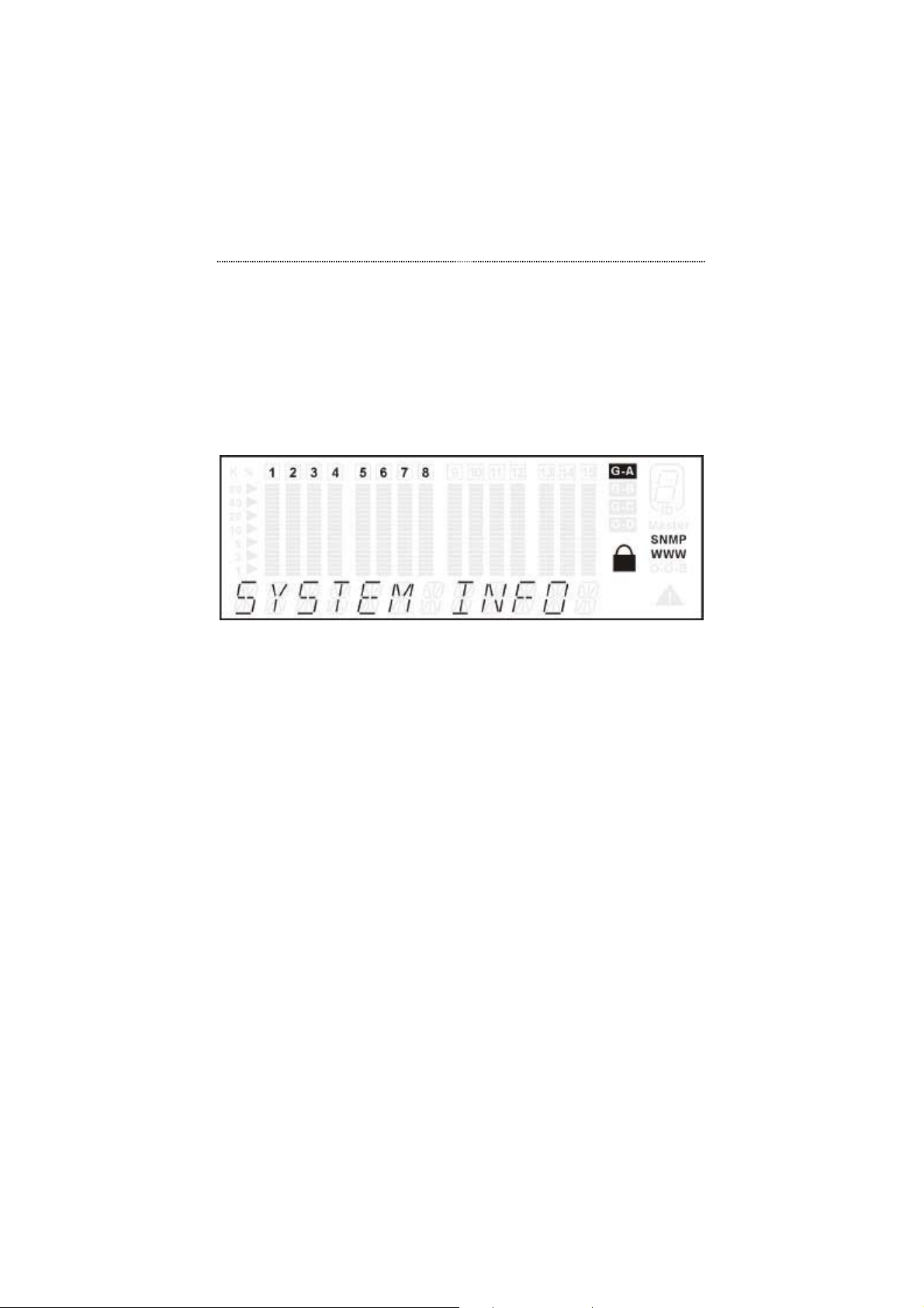
The SYSTEM INFO menu shown in Figure 3.39 allows users to view system
information.
Press Prev or Next in the MAIN MENU to select SYSTEM INFO.
Figure 3.39 System Information Menu
Press Enter to view system information.
The following system information is automatically displayed in the message
zone:
• HARDWARE VERSION
• SOFTWARE VERSION
• IP ADDRESS
• SUBNET MASK
• DEFAULT GATE WAY
Page 66

Chapter
In this chapter, you will learn how
anage
4
Setting-Up for
Console
M
to configure your Switch for
management through the
terminal emulation program.
ment
Page 67

4-2 Setting-Up for Console Management
Chapter 4 Setting-Up for Console Management
Managing The Switch
Several parameters of the Switch must be configured before you are able to
access it via a Telnet session, the Web-Based Management interface or
SNMP. The parameters include the IP address, subnet mask and default
gateway. These parameters can be configured via the Front Panel Display or
the Console program, which is accessed through a PC terminal emulation
program that supports VT100.
The Switch can be managed through the Console Program, Telnet, Web
Management or SNMP. This chapter describes setting up for management,
which is done through the Console program.
Console Program
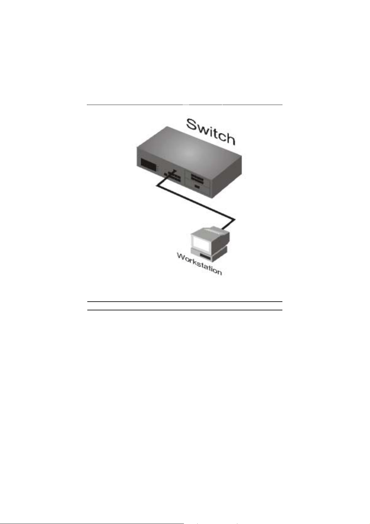
To configure the system, connect an EIA-232 serial cable to a COM port on a
PC or notebook computer and to the Console Port of the Switch as shown in
the following figure.
Page 68
Setting-Up for Console Management 4-3
Figure 4.1 Connecting a PC via Console Port.
Note: Do not use a null modem cable.
Setting-Up the Terminal Program
A Terminal Program is required to communicate with The Switch’s internal
software. An MSDOS based program such as PC-PLUS can make the
connection with the device’s built-in software. The COM port should be
configured as:
Baud: 9600
Parity: None
Data bits: 8
Stop bits: 1
Flow control: None
Page 69
4-4 Setting-Up for Console Management
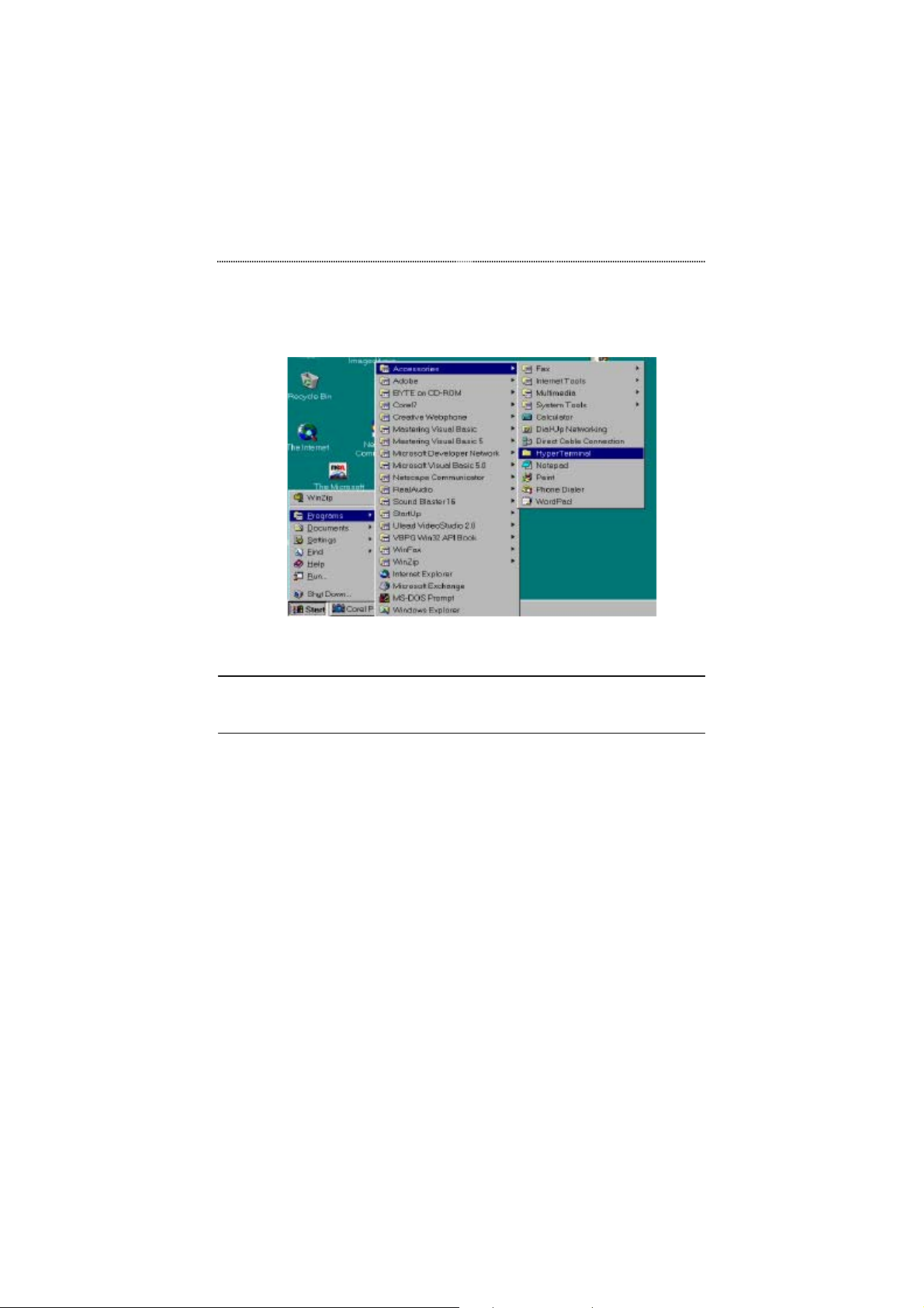
Windows95 provides a suitable program called HyperTerminal and is
accessed from the Start menu. Click START, then Programs, Accessories and
then HyperTerminal.
Figure 4.2 Terminal Program.
An MS-DOS type terminal program can also make the connection with
the Switch’s built in software. However, this section describes using
Windows 95 or 98 HyperTerminal.
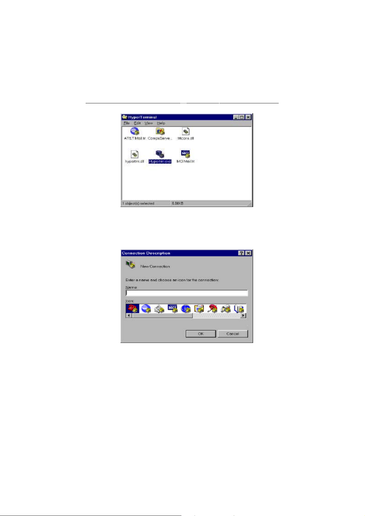
From the HyperTerminal Screen, double click the Hypertrm.exe icon.
Page 70
Setting-Up for Console Management 4-5
Figure 4.3 Hypertrm.exe Icon
The Connection Description Screen is displayed. Type a name in the Name
panel to identify the connection, choose an icon (optional) and click OK.
Figure 4.4 New Connection Screen.
The following screen prompts for your country info, area code, telephone
number and the modem type. Since you won’t be dialing out via a modem
you only need to set the COM port. Click the arrow at the right of the
“Connect using” label. Select the correct COM port and press the keyboard
ENTER key. (Usually COM 2 when a mouse is connected to COM1)
Page 71
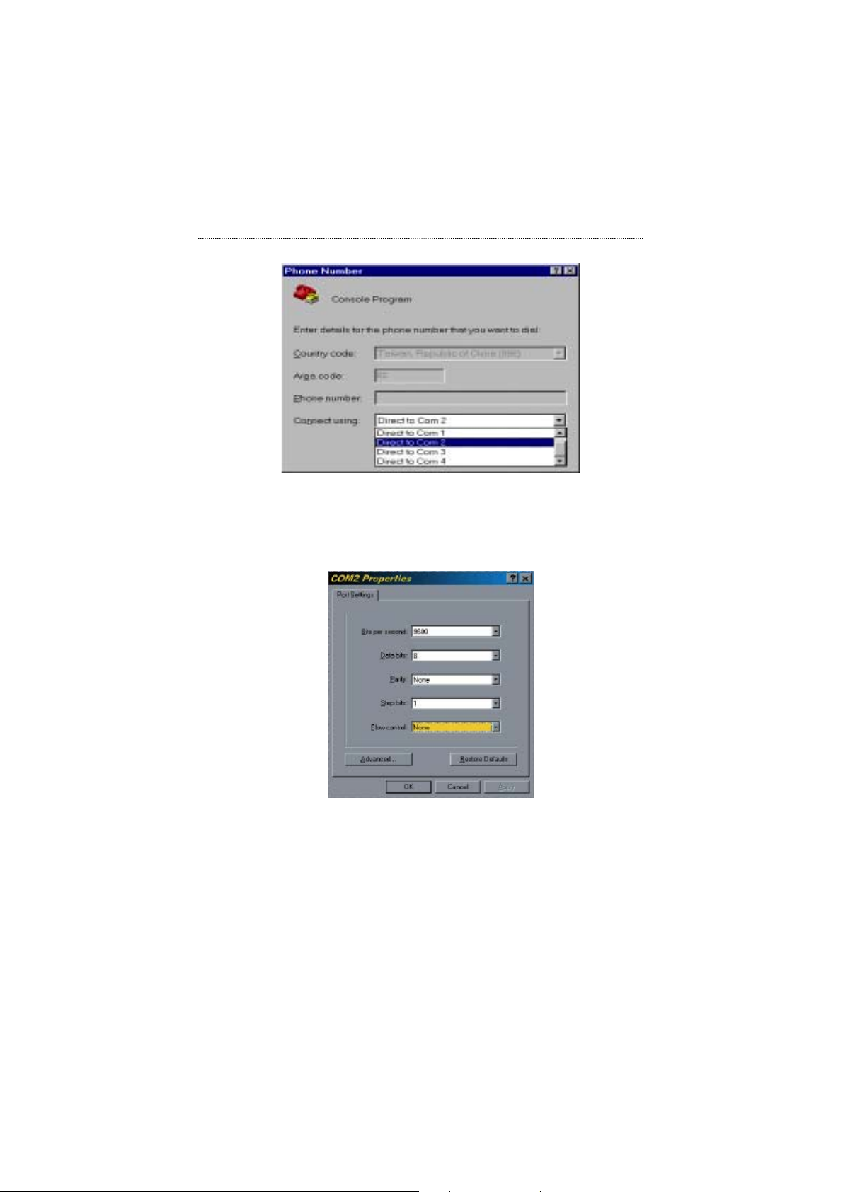
4-6 Setting-Up for Console Management
Figure 4.5 Selecting a COM port.
In the next screen all settings must be set correctly; Bits/sec “9600”, Data bits
“8”, Parity “None”, Stop bits “1” and Flow Control “None” as in the figure
below.
Figure 4.6 Port Settings
Click the OK button and the connection to the terminal program will be
complete.
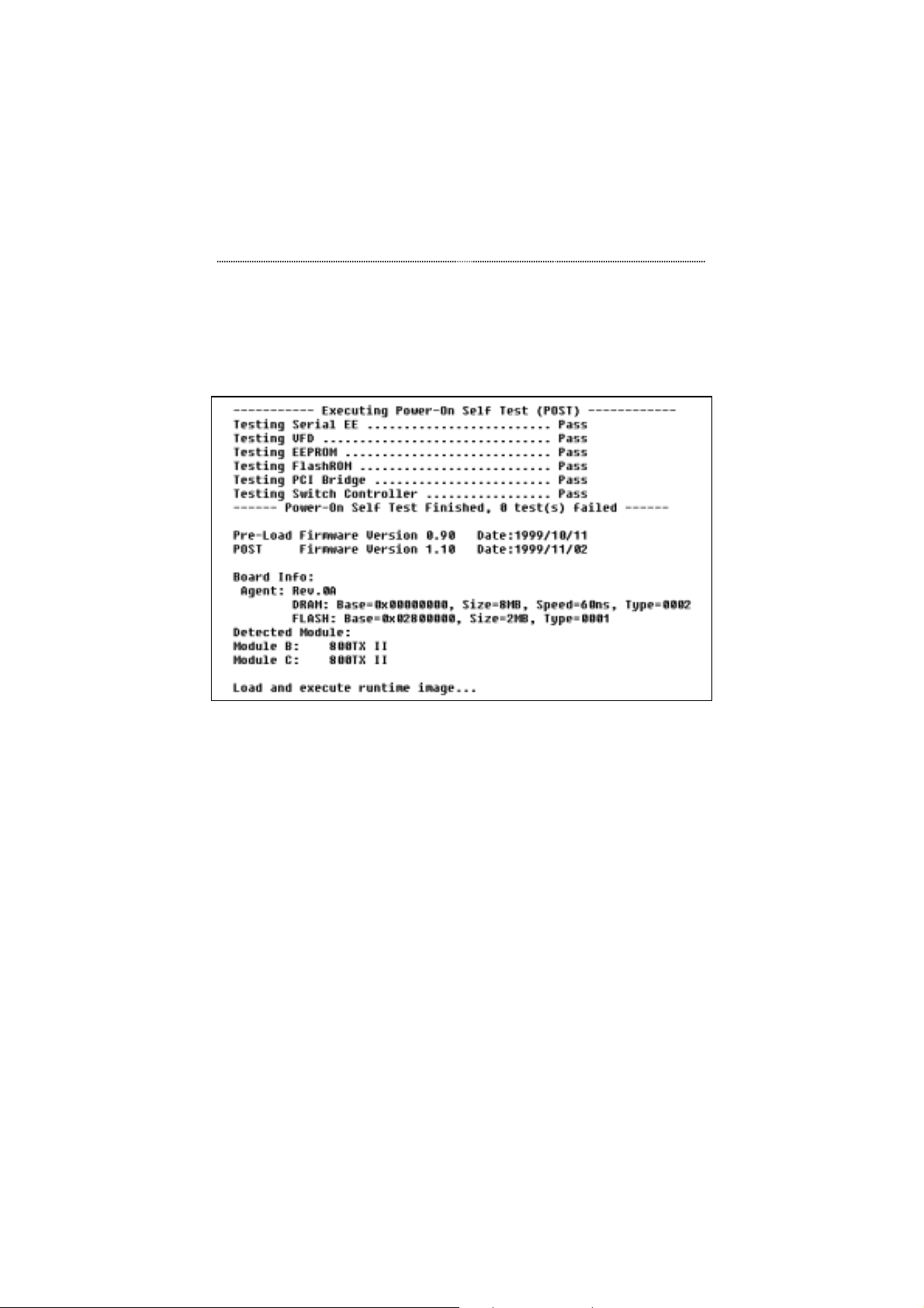
You should now see the POST screen as shown in Figure 4.7.
Page 72
Setting-Up for Console Management 4-7
Power On Self Test
When the Switch is powered up, the Power On Self Test, appears in the
HyperTerminal window as shown in Figure 4.7.
Figure 4.7 Power On Self Test
As the Switch’s tests are run through, the test and their results will be
displayed. These tests can also be seen in the Front Panel Display’s display
on the Switch. After the tests are complete, the Console program’s logon
screen appears.
Note that in some cases, an additional menu will appear before the Login
Screen. See “POST Download Menu” on page 4-11 for more information.
Note that if the Switch was already powered up when HyperTerminal was
started, then the screen will be blank because the Switch’s Power On Self
Test will have run already. Therefore, the screen needs to be refreshed in
order for the Login Screen to appear. Press CTRL + R to refresh the screen.
Page 73
4-8 Setting-Up for Console Management
Navigating the Console Program
Screens
Use the following keyboard keys to navigate through the menu and select a
sub-menu. These keyboard commands are common to all menus.
TAB KEY: Use the TAB key to select screen menus.
ENTER KEY: Press the ENTER key after selecting a menu item
with the TAB key to view the selection’s sub-
menu.
EXIT: Return to the previous menu.
HELP: Select HELP to view keyboard commands.
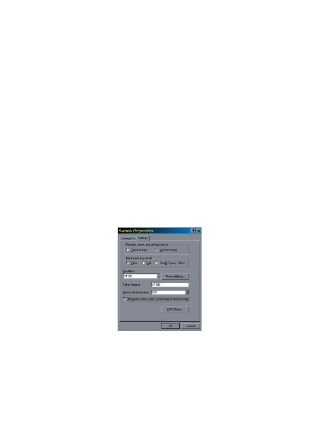
Note that if you are not able to input commands through your PC keyboard,
check to be sure that the Windows keys radio button is selected and the
Emulation is set to VT100 in the File/Properties menu as shown in Figure
4.8.
Figure 4.8 The Terminal Emulation Properties Menu
Page 74
Setting-Up for Console Management 4-9
Login Screen
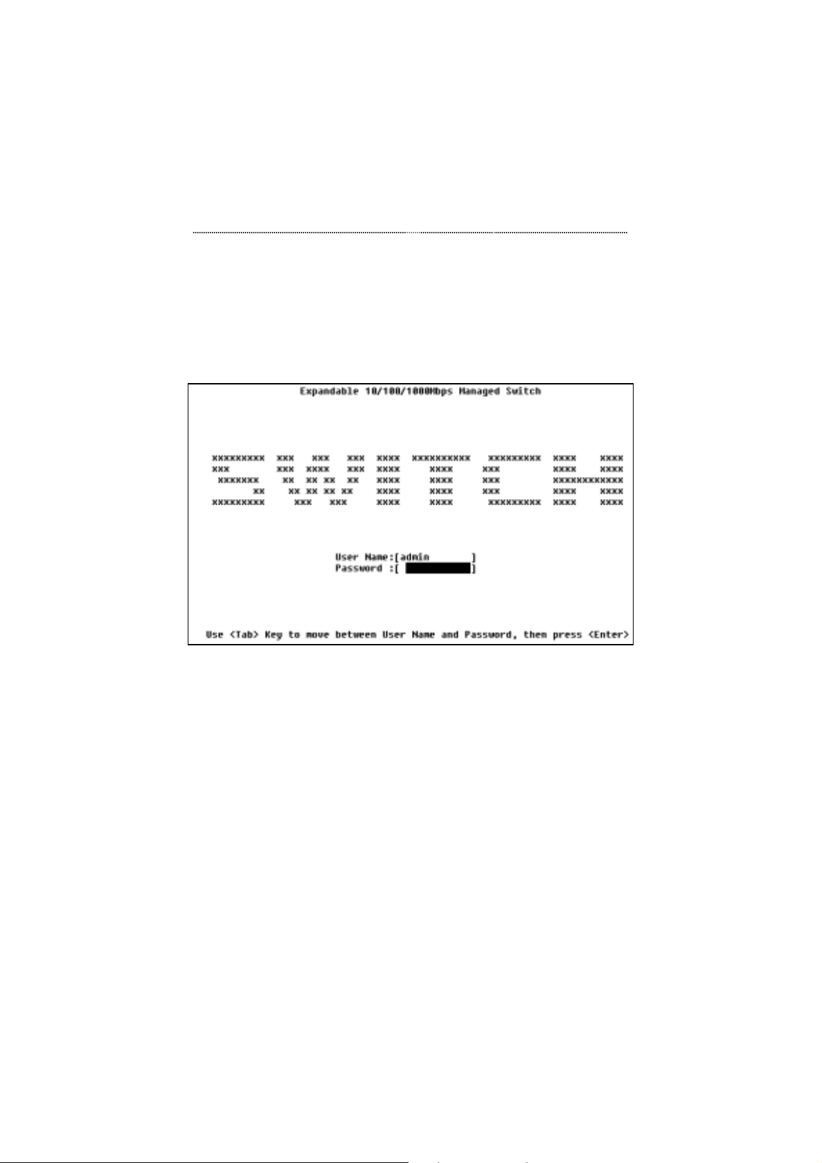
The Login Screen appears as show in Figure 4.9. If there is no text in the
Hyper Terminal screen at this point, press Enter a few times and the Login
Screen will appear.
Figure 4.9 The Login Screen
User Name and Password
The factory default user name is "admin".
The factory default password is an empty string (i.e. you do not need to enter
anything into the Password field).
After entering the user name and pressing Enter in the password field, the
main menu will appear.
Page 75
4-10 Setting-Up for Console Management
Note that if you enter the user name or password incorrectly, when you press
Enter, the field highlight will scroll back to User Name, and access will not
be granted.
Main Menu
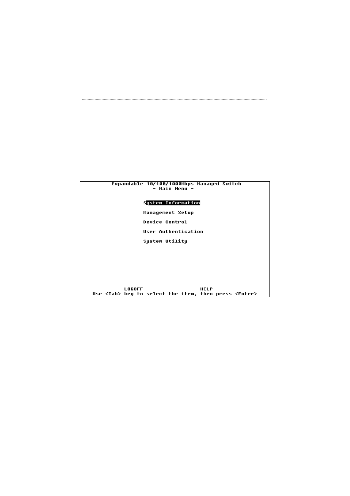
After passing through the login security screen, the Main Menu for console
management is displayed as shown in Figure 4.10.
Figure 4.10 Main Menu
There are 5 sub-menu selections for Switch management: System
Information, Management Setup, Device Control, User Authentication and
System Utility. Please see Chapter 5, Console Management, for complete
instruction.
Page 76
Setting-Up for Console Management 4-11
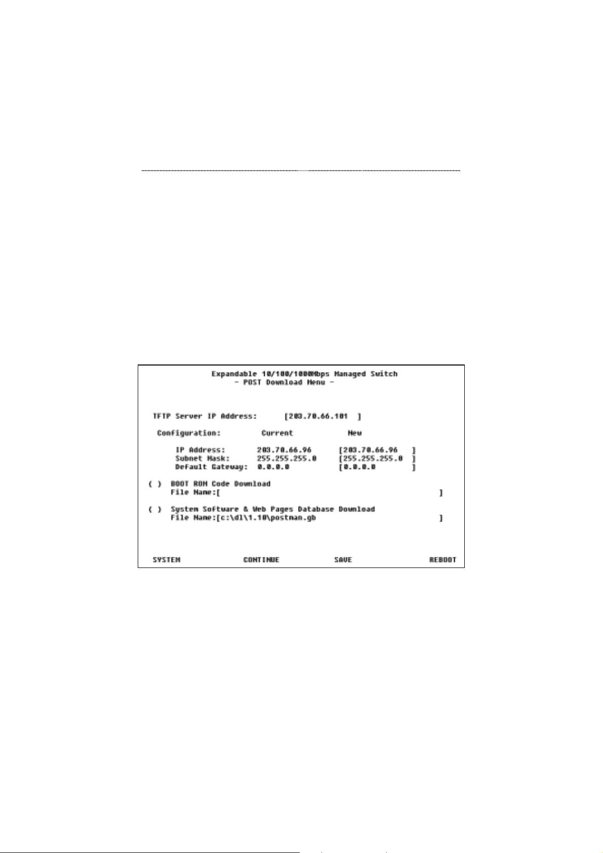
POST Download Menu
The POST Download Menu will appear as shown in Figure 4.11 under the
following circumstances:
• When there is no valid system firmware in the Switch's flash memory
• When a TFTP download operation fails
• When the user presses Ctrl-C during the Power On Self Test
Note that pressing Ctrl-C during the Power On Self Test is a quick and
convenient way to assign new network configurations to the Switch or
download Boot ROM code and system software.
Figure 4.11 POST Download Menu
Page 77

4-12 Setting-Up for Console Management
TFTP Server IP Address
If you want to download system software from a TFTP server, enter the
TFTP server IP address in this field.
Network Configuration
Use the tab key to highlight IP Address listed under the heading New. Enter
the IP address for the switch. Repeat this step for the Subnet Mask and
Default Gateway. Select the SAVE command and press Enter to save your
configuration settings.
Boot ROM Code Download
If you want to request a boot ROM code download for the Switch, place an X
in the check box and enter the path for the file in this field.
System Software & Web Pages Database
Download
If you want to request a system software and web page database download
for the Switch, place an X in the check box and enter the path for the file in
this field.
POST Commands
The following describes the command options that are available at the bottom
of the POST Download Menu screen.
• SYSTEM Closes the POST Download Menu and executes the system
runtime software without performing any configuration changes or
software downloads.
• CONTINUE Executes a software download without rebooting. Note
that Network Configuration changes will not be configured.
Page 78

Setting-Up for Console Management 4-13
• SAVE Saves changes to this screen without exiting.
• REBOOT Reboots the switch, thus configuring all Network
Configuration changes and executes all selected software downloads.
Page 79

Chapter
This chapter will provide you with
g
5
Console
Mana
complete information on using
the powerful console
management interface.
ement
Page 80

5-2 Console Management
Chapter 5 Console Management
Introduction
Console Management is used to manage the switch. It runs from a terminal
program on a computer connected to the switch’s Console port via an RS-232
cable. See Chapter 4, “Setting-Up for Management”, for information about
using a terminal program. Console Management is also used to configure
settings that enabling using the more user-friendly Web-Based management
and for more detailed SNMP management. Some of the configuration
settings will be visible in the Front Panel Display, such as a disabled port.
After configuring this switch with Console Management, it can then be
monitored and configured with the either Console Management, Web-Based
management using a web browser, SNMP using programs such as HP
OpenView or any combination of these three.
Using a Telnet Session
The following management interface is the same, whether you are using the
Console management, or a Telnet session.
In order to conduct a Telnet management session, you must first configure
the Switch’s IP address. This can be done via the Front Panel Display or a
Console management session. Please refer to the respective sections in this
manual for the relevant information on setting the switch’s IP address.
Using any Telnet application that emulates VT100 over a TCP/IP network,
please establish a connection to the Switch. If you need help doing this,
please refer to your Telnet application documentation.
Page 81

Console Management 5-3
Navigating the Console Program
Screens
The Console management uses limited keyboard keys such a Tab, Enter, and
Ctrl + “letter” combinations to execute its commands. A glossary of
commands can be found in the Help menu. These command keys and their
functions are described as:
TAB KEY: Use the TAB key to select screen menus.
ENTER KEY: Press the ENTER key after selecting a menu item
with the TAB key to view the selection’s sub-
menu.
EXIT: Return to the previous menu.
HELP: Select HELP to view keyboard commands.
Getting Started
To start using console management, login through a terminal program. If you
need help establishing a terminal connection, please refer to Chapter 4,
Setting-Up for Console Management.
Login Screen
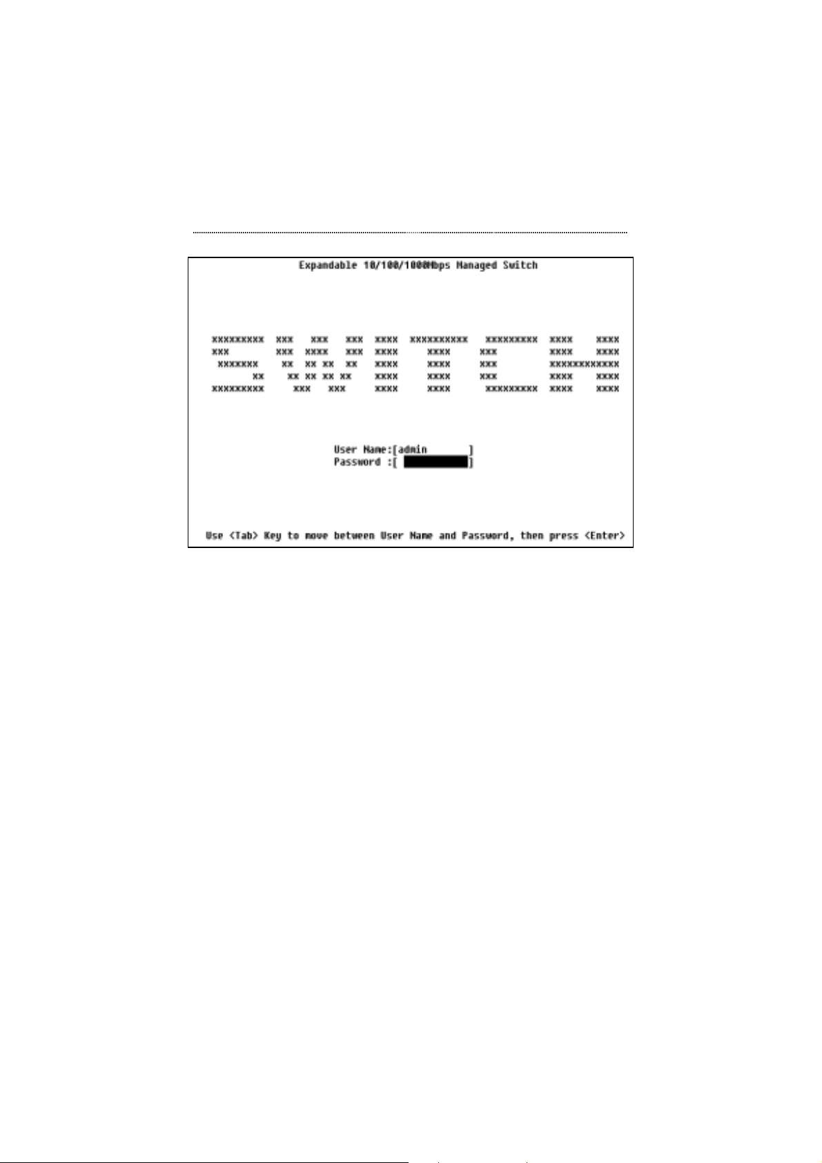
Once you have successfully established a terminal connection, the Login
screen will appear as shown in . You may have to press Enter a couple times
to refresh the screen. If you still don't see the Login screen, please refer to
Chapter 4, Setting-Up for console management for more information.
Page 82
5-4 Console Management
Figure 5.1 Login Screen
User Name and Password
The factory default user name is "admin".
The factory default password is an empty string (i.e. you do not need to enter
anything into the Password field).
After entering the user name and pressing Enter in the password field, the
main menu will appear.
Note that if you enter the user name or password incorrectly, when you press
Enter, the field highlight will scroll back to User Name, and access will not
be granted.
Page 83
Console Management 5-5
Main Menu
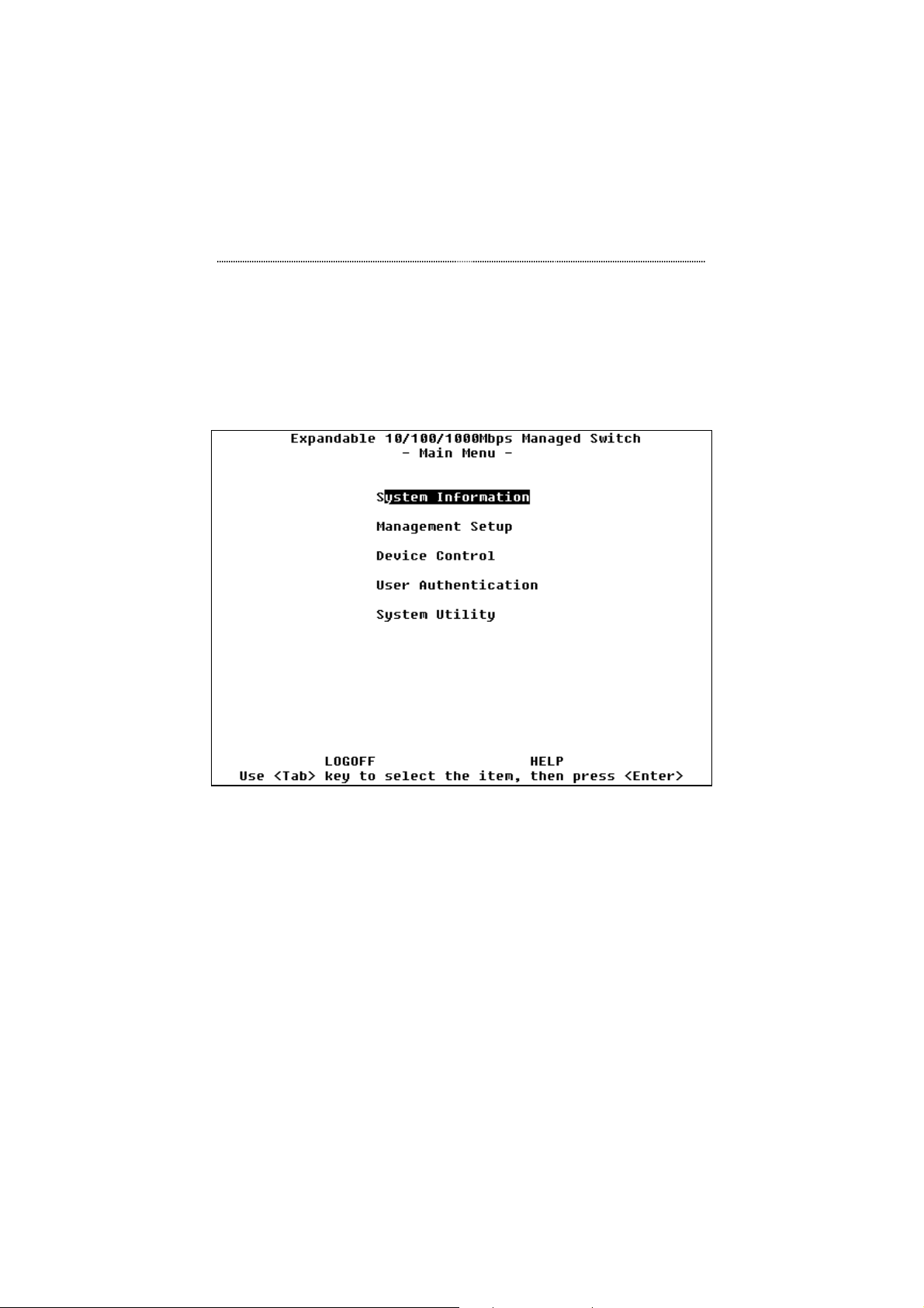
The Main Menu consists of five sub-menus, grouping different system
configuration topics.
Figure 5.2 Main Menu
Help Menu
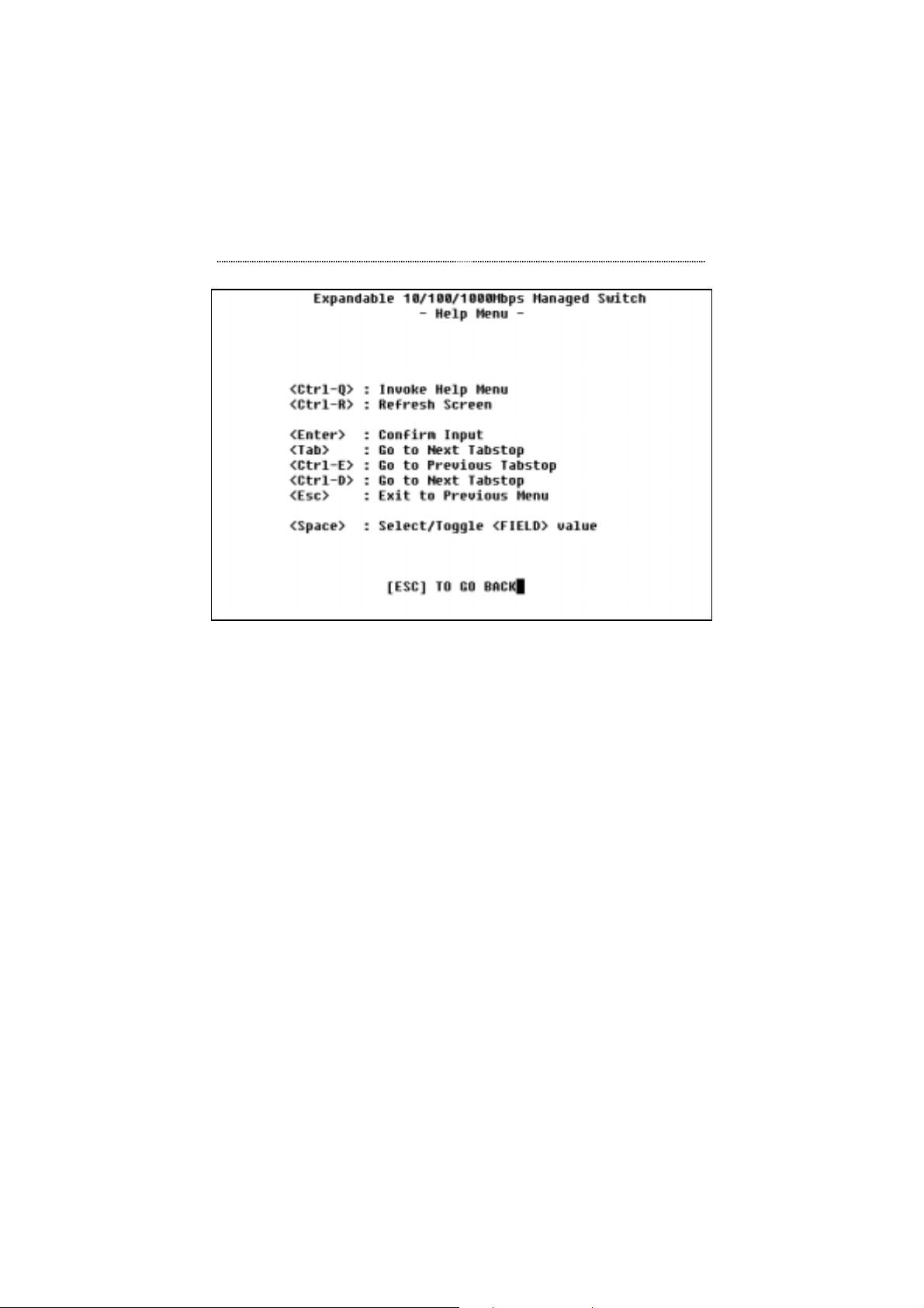
Selecting HELP at the bottom of the menu screens and pressing Enter
accesses the Help Menu. The help menu will appear as shown in Figure 5.3.
Page 84
5-6 Console Management
Figure 5.3 Help Menu
System Information
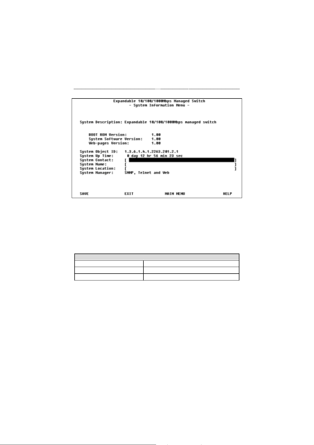
The Main Menu item, System Information, is shown in Figure 5.4.
Page 85
Console Management 5-7
Figure 5.4 System Information Menu
The System Information Menu provides version identification of the systems
built-in software, which may be useful in the-event of any future upgrades
becoming available. It also provides you with common system information.
The following information settings can be edited and saved to memory by
users that login with Read/Write privileges.
System Information
System Contact Up to 64 alpha numeric characters
System Name Up to 64 alpha numeric characters
System Location Up to 64 alpha numeric characters
Table 5.1 System Information
To save and write the system information to memory, select SAVE and press
the Enter keyboard key. The new information is written to memory and
permanently stored until it is edited or changed by users with Read/Write
privileges.
Page 86
5-8 Console Management
Management Setup
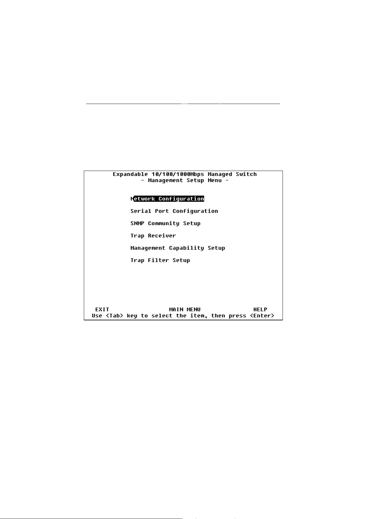
The Main Menu item, Management Setup, has several sub-menus. The
Management Setup Menu is shown in Figure 5.5.
Figure 5.5 Management Setup Menu
The Management Setup Menu has 5 sub-menus for Network configuration
and for configuring the SNMP community and Trap community.
Page 87
Console Management 5-9
Management Setup
Network Configuration Set IP, Subnet Mask and Default Gateway
address.
Serial Port Configuration View management port (RS-232)
configuration.
SNMP Community Setup Configure community names and access.
Trap Receiver Configure addresses to which trap messages
will be sent.
Management Capability
Setup
Trap Filter Setup Configure trap filters
Enable or Disable Web management.
Table 5.2 Management Setup
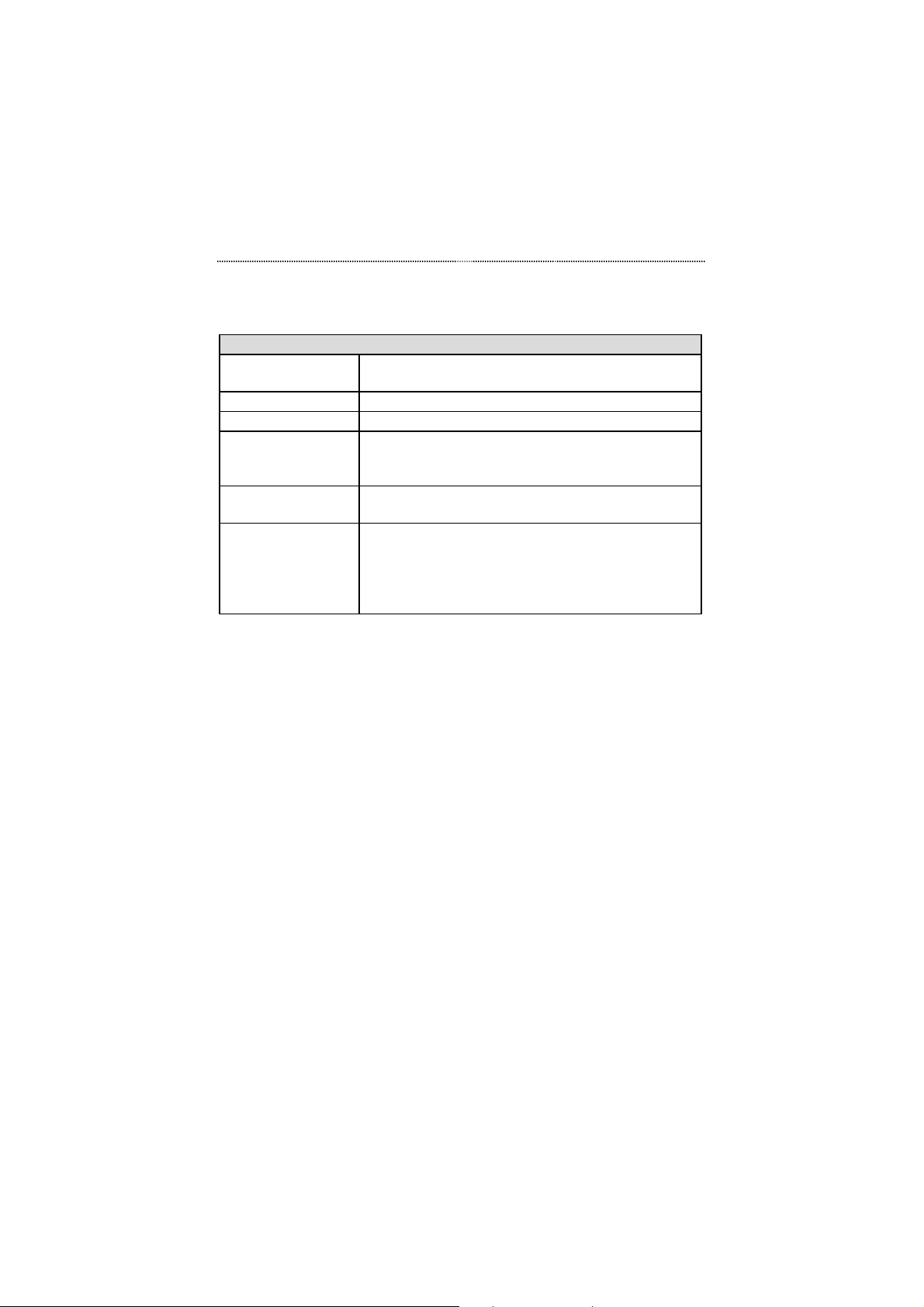
Network Configuration
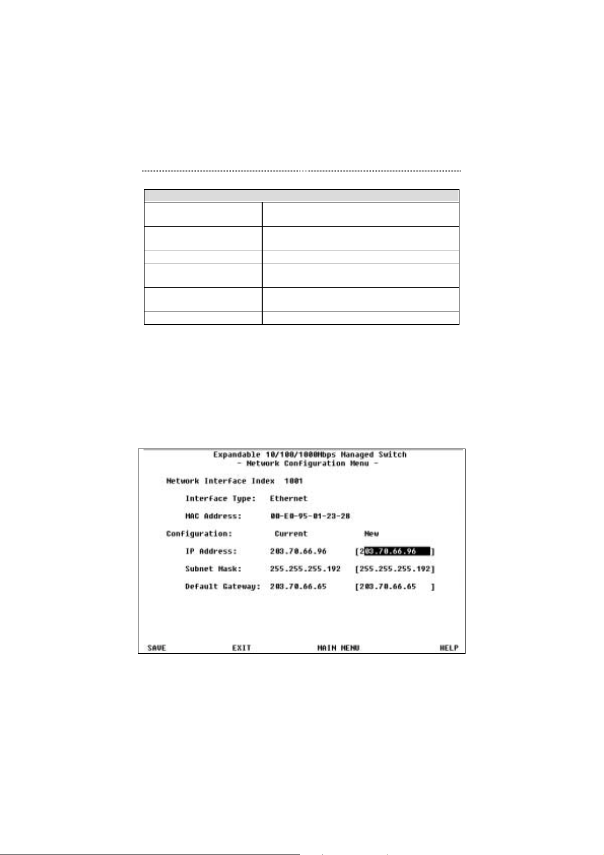
The Management Setup Menu item, Network Configuration, is shown in
Figure 5.6.
Figure 5.6 Network Configuration Menu
Page 88
5-10 Console Management
The Network Configuration Menu is used to configure the IP Address,
Subnet Mask and Default Gateway.
Network Configuration
Network Interface
Index
Interface Type Indicates the current management interface type
MAC Address Indicates the current MAC address
IP Address Internet Protocol address, identifying the switch,
Subnet Mask This number together with the IP address identifies
Default Gateway A gateway is a connection or interchange point that
Indicates Ethernet as the management interface type
consisting of four numbers from 0 to 255, separated
by periods.
the network your computer is on.
connects two networks that would otherwise be
incompatible. For example, a local area network
(LAN) may need a gateway to connect it to a wide
area network (WAN) or to the internet.
Table 5.3 Network Configuration
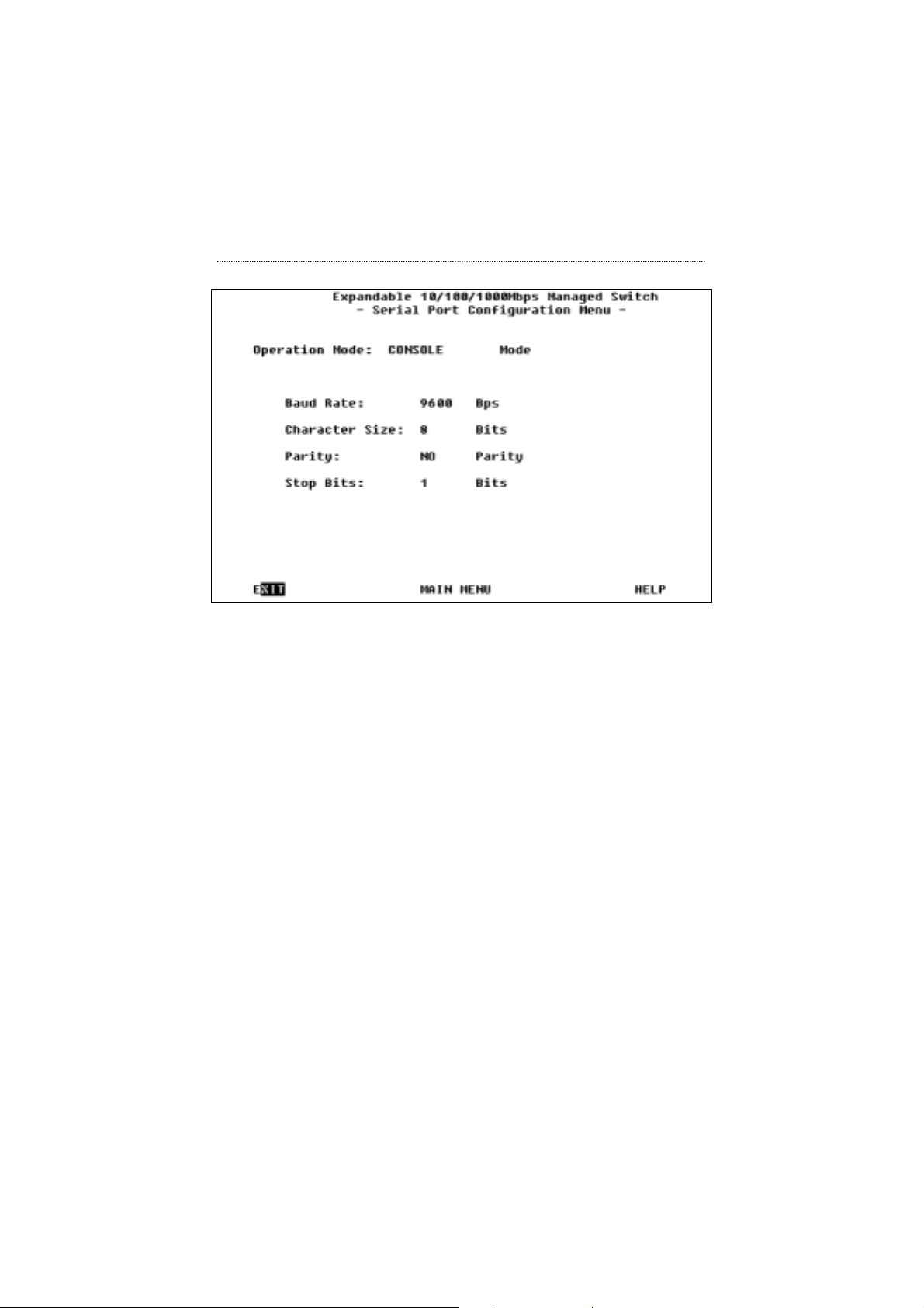
Serial Port Configuration
The Management Setup Menu item, Serial Port Configuration, is shown in
Figure 5.7.
Page 89
Console Management 5-11
Figure 5.7 Serial Port Configuration Menu
The Serial Port Configuration Menu displays the settings that are required for
the terminal connection that allows the Switch to communicate with a
computer via the console port connected by an RS-232 cable to a computer’s
serial port.
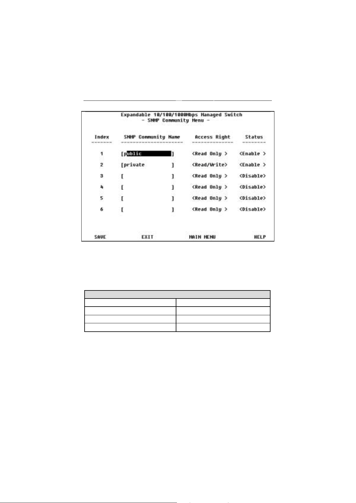
SNMP Community Setup
The Management Setup Menu item, SNMP Community Setup, is shown in
Figure 5.8.
Page 90
5-12 Console Management
Figure 5.8 SNMP Community Setup Menu
The SNMP (Simple Network Management Protocol) Community Setup is
similar to setting up passwords and access rights for Console Management or
Web-Based management. Up to six community names can be configured
with access and status rights.
SNMP Community Setup
Index 1~6
SNMP Community Name A name of up to 16 characters.
Access Rights Read/Write or Read Only
Status Enabled or Disabled
Table 5.4 SNMP Community Setup
To add or edit an SNMP Community entry, highlight the desired fields and
make the appropriate entries. When all settings are configured, highlight
SAVE and press Enter.
Page 91
Console Management 5-13
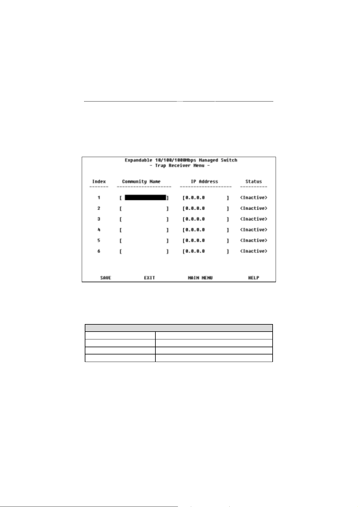
Trap Receiver Menu
The Management Setup Menu item, Trap Receiver, is shown in Figure 5.9.
Figure 5.9 Trap Receiver Menu
Trap messages will be sent to all entries that have an Active status. Entering
their names, setting their IP addresses and enabling their Status configures
the trap receivers.
Trap Receiver Menu
Index 1~6
Community Name Name of a trap receiver up to 16 characters
IP Address IP Address of the trap receiver
Status Inactive or Active
Table 5.5 Trap Receiver Menu Commands
Page 92
5-14 Console Management
To add or edit a trap receiver, press the Tab key to select the desired field and
make the appropriate entries. To save the information, highlight the SAVE
command and press the Enter key.
Management Capability Setup
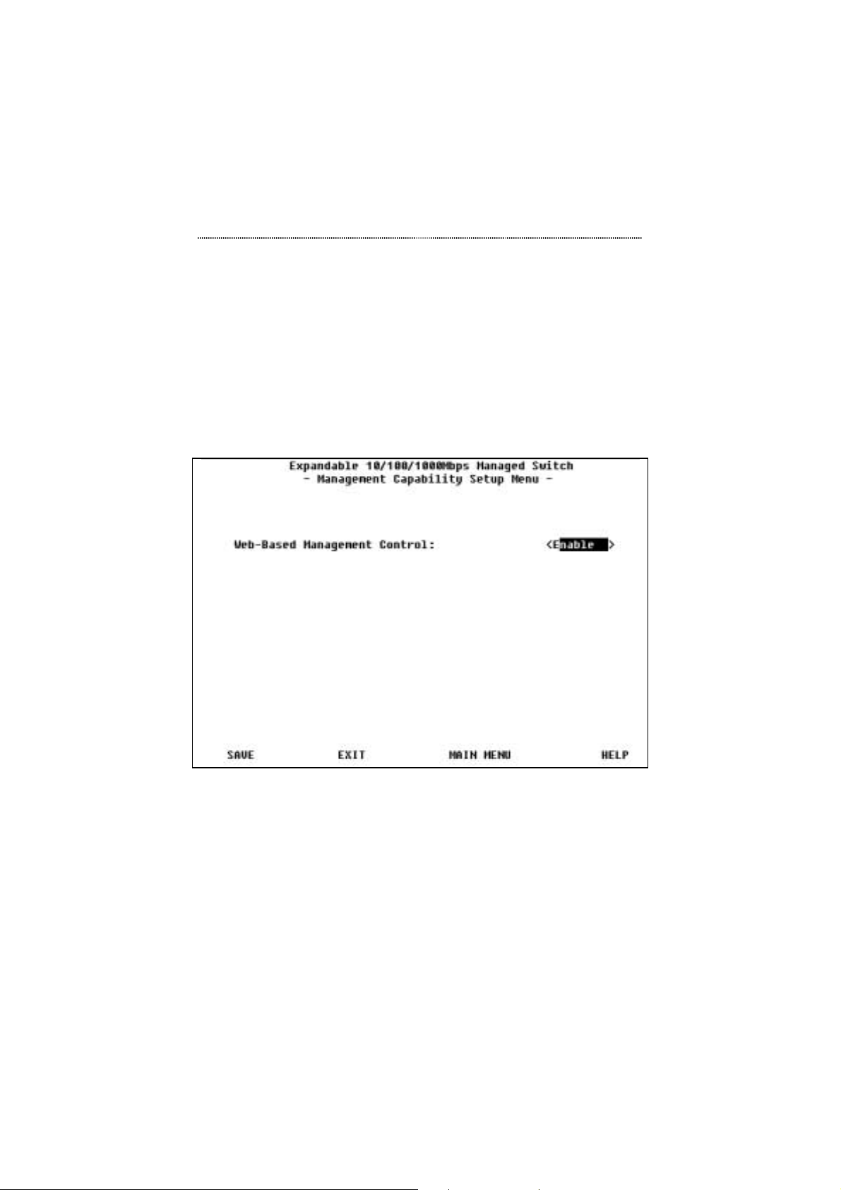
The Management Setup Menu item, Management Capability Setup, is shown
in Figure 5.10.
Figure 5.10 Management Capability Setup Menu
The Management Capability Setup menu is used to enable or disable WebBased management. Highlight and select Enabled to allow access via WebBased management. Select Disabled to block access via Web-Based
management.
Page 93
Console Management 5-15
Trap Filter Setup
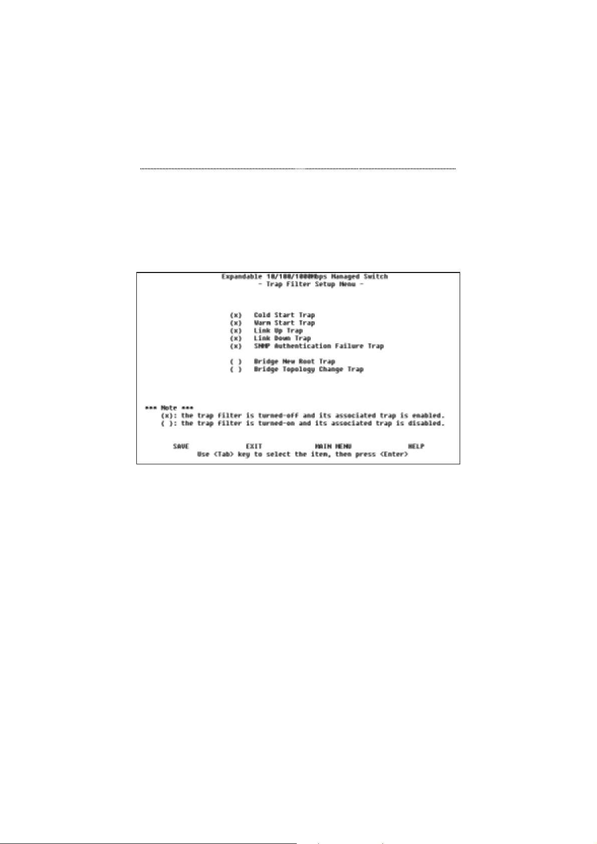
The Management Setup Menu item, Trap Filter Setup, is shown in Figure
5.11.
Figure 5.11 Trap Filter Setup Menu
The Trap Filter Setup Menu allows you to control which traps are sent.
To have a trap message sent when a trap event occurs, place an “X” before
the function listed. To prevent a trap message from being sent when a trap
event occurs, remove the “X” before the function listed. Select SAVE before
exiting to save the new settings.
Page 94
5-16 Console Management
Device Control
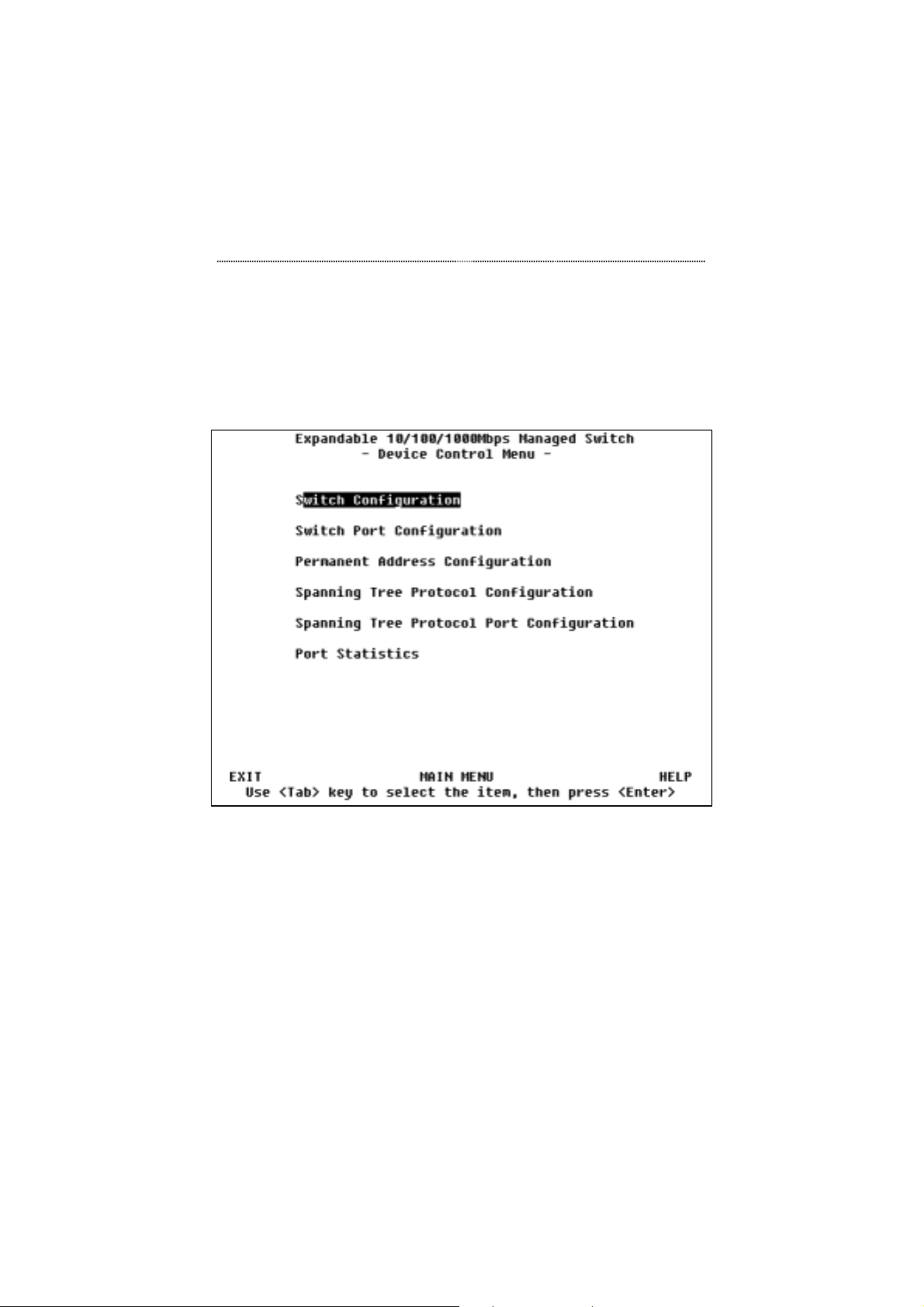
The Main Menu item, Device Control, has several sub-menus. The Device
Control Menu is shown in Figure 5.12.
Figure 5.12 Device Control Menu
The Device Control Menu is used to view and or configure the Switch and
it's ports. The switch’s ports can be configured without regard to any actual
link ups, managed slaves hubs by contrast must be linked before they can be
configured.
The following is a brief overview of the Device Control sub-menus:
Page 95
Console Management 5-17
Device Control
Switch Configuration Set the monitoring port and aging time
of the system
Switch Port Configuration Name ports and set their status
Permanent Address
Configuration
Spanning Tree Protocol
Configuration
Spanning Tree Protocol Port
Configuration
Port Statistics Display the port statistics
Table 5.6 Device Control
Configure the permanent address entry
Configure the Spanning Tree Protocol
parameters and view STP status
Naming and configuring individual
ports within the virtual LANs.
Switch Configuration
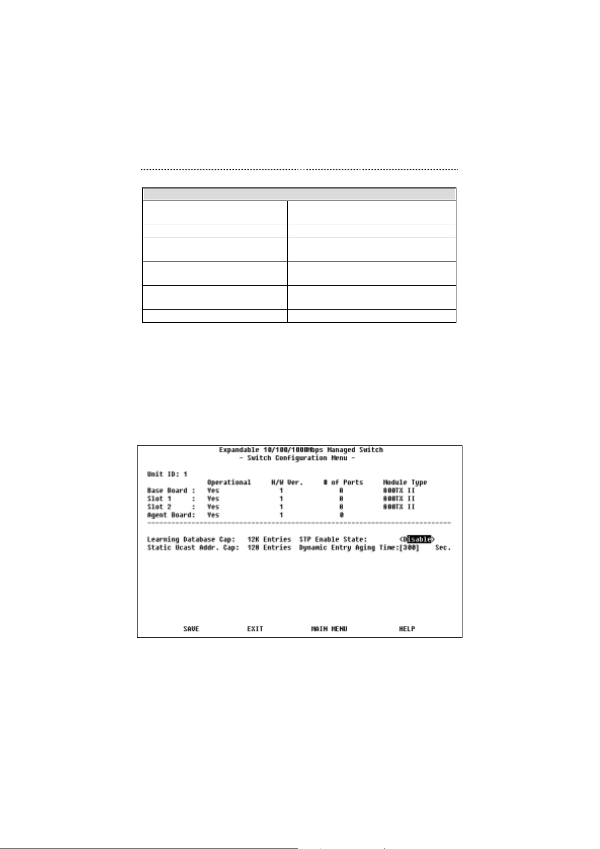
The Device Control Menu item, Switch Configuration, is shown in Figure
5.13.
Figure 5.13 Switch Configuration Menu
Page 96
5-18 Console Management
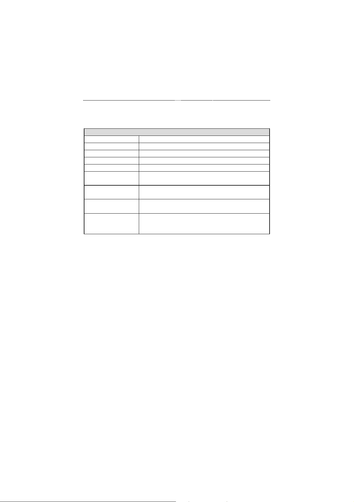
The Switch Configuration Menu displays the settings of the switch and
allows the configuration of several settings.
Switch Configuration Menu
Unit ID The unit ID of the Switch
Operational States the operational status of the associated board
H/W Ver. States the hardware version of the board
# of Ports Number of ports in the associated board
Module Type The module type of the associated board
Learning Database
Capability
Static Unicast
Address Capability
STP Enable State Enables or disables Spanning Tree Protocol for the
Dynamic Entry
Aging Time
The capability of the learning database in the
Switch
The maximum number of static unicast addresses
that the Switch can store
Switch
Specifies the aging time of dynamic entries in the
learning database from 10 to 440 seconds. The
default is 300 seconds.
Table 5.7 Switch Configuration Menu Options
Switch Port Configuration
In the Device Control Menu item, Switch Port Configuration, there are two
menus used to configure the Switch's individual ports: The Switch Port
Configuration Overview Menu and the Switch Port Configuration Menu.
Switch Port Configuration Overview Menu
The Switch Port Configuration Overview Menu is shown in Figure 5.14.
Page 97
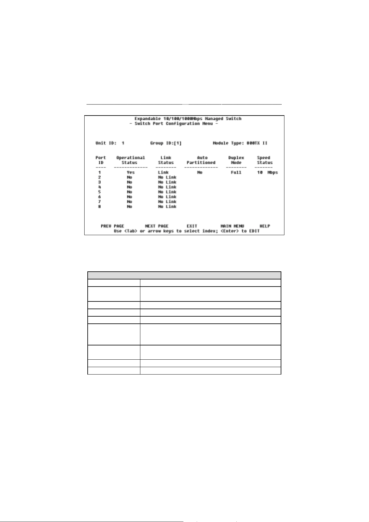
Console Management 5-19
Figure 5.14 Switch Port Configuration Overview Menu
The Switch Port Configuration Overview Menu is used to observe current
individual port status and select individual ports for configuration.
Switch Port Configuration Overview Menu
Unit ID The unit ID of the Switch
Group ID Allows you to select a port group (1=G-A, 2=G-B,
3=G-C)
Module Type States the module type for the selected port group
Port ID The port for which data in that row applies
Operational Status The operational status of the port
Link Status Presents the current link state of the connection. Link
Status is accurate even if a port has been manually
disabled.
Auto Partitioned Shows whether or not the port has been auto-
partitioned
Duplex Mode Shows current duplex mode for the port
Speed Status Shows the current speed of the port
Table 5.8 Switch Port Configuration Overview Menu Options
To select a port for configuration, tab to highlight a Port ID number and press
the Enter key. You will then see the Switch Port Configuration Menu.
Page 98
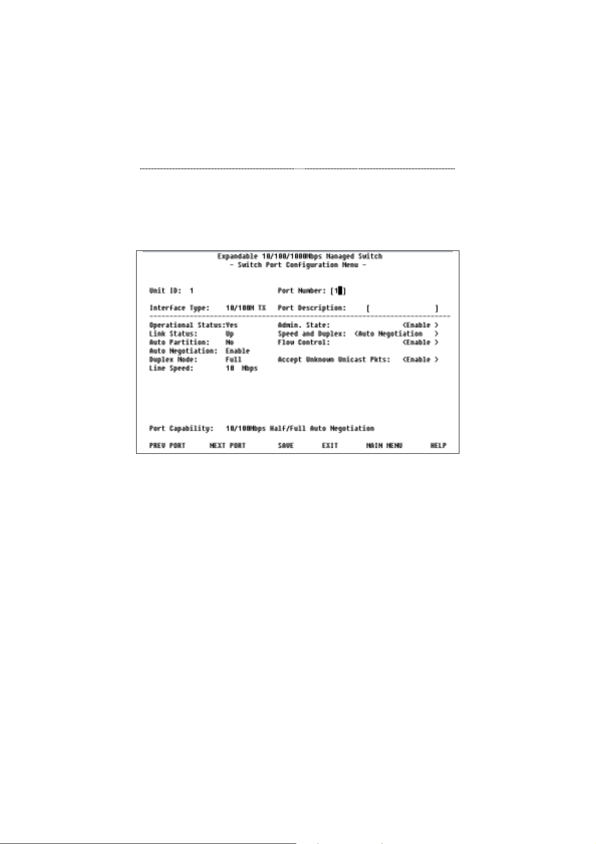
5-20 Console Management
Switch Port Configuration Menu
The Switch Port Configuration Menu is shown in Figure 5.15
Figure 5.15 Switch Port Configuration Menu
The top of this screen describes the selected port. The left side of the screen
displays the current port configuration. The fields on the right side allow you
to configure new settings for the port. The bottom of the screen states the
capabilities of the selected port and allows you to move between ports.Be
sure to select SAVE and press the Enter key before moving to another port if
you want to save the new configuration for the port.
Page 99
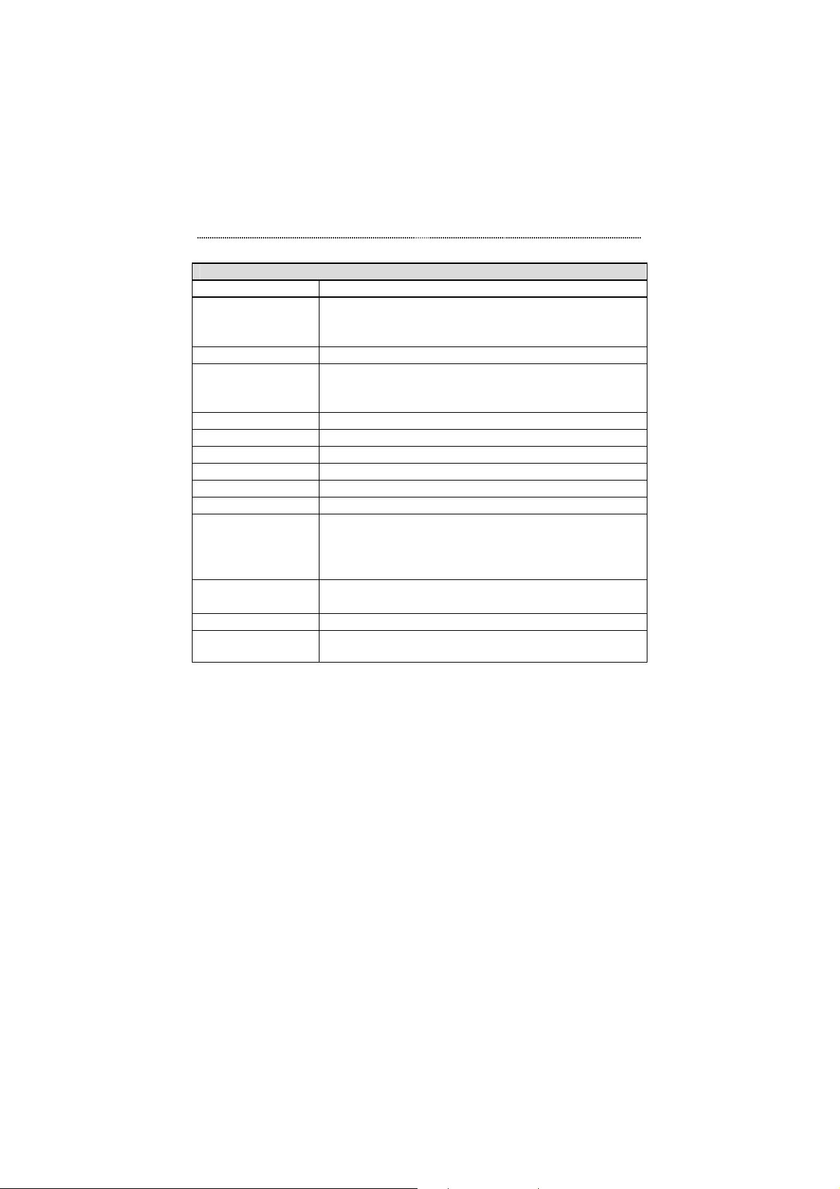
Console Management 5-21
Switch Port Configuration Menu Settings
Unit ID The unit ID of the Switch.
Port Number Specifies which port is displayed. You can enter a
port number here and press the Enter key to select
different ports.
Interface Type The network interface type for the port.
Port Description Specifies the name given to the port that is currently
displayed. You can use up to sixteen characters to
designate a port name.
Operation Status The operational status of the port
Link Status The link status of the port
Auto Partition The auto partition status of the port
Auto Negotiation The auto negotiation status of the port
Duplex Mode The duplex mode of the port
Line Speed The line speed of the port
Admin. State Enables or disables the current port. If Disable is
selected, the port will be partitioned and the amber
frame enclosing the port number on the Front Panel
Display will become lit.
Speed and Duplex The speed and duplex of this port configured by the
user
Flow Control Enable or Disable flow control
Accept Unknown
Unicast Pkts
Specify whether or not to accept unknown unicast
packets.
Table 5.9 Switch Port Configuration Menu Settings
Permanent Address Configuration
In the Device Control Menu item, Permanent Address Configuration, there
are two menus used to configure the Switch's permanent address entries. The
first Permanent Address Configuration Menu is used to view the current
permanent address configurations. The second Permanent Address
Configuration Menu is used to configure new settings.
Page 100
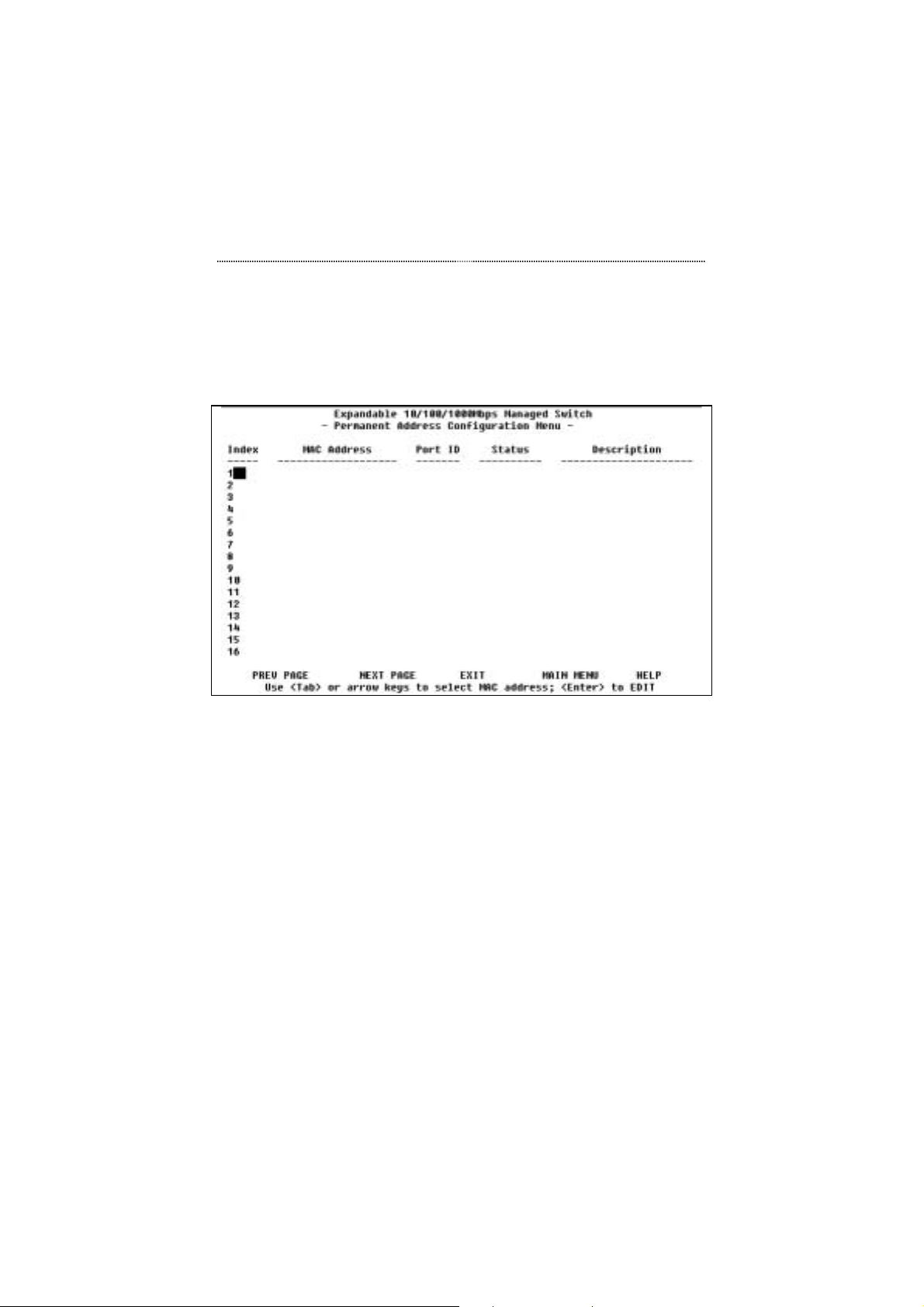
5-22 Console Management
Permanent Address Configuration Menu (View)
The first Permanent Address Configuration Menu for viewing current
configurations is shown in Figure 5.16.
Figure 5.16 Permanent Address Configuration Menu (View)
The Permanent Address Configuration Menu displays current information on
all permanent addresses currently stored in the Switch. To edit a permanent
address, tab to select an Index number and press the Enter key. You will then
see the second Permanent Address Configuration menu.
Permanent Address Configuration Menu (Edit)
The second Permanent Address Configuration Menu for editing
configurations is shown in Figure 5.17.
 Loading...