

Page 1

LevelOne
GSW-0506
GSW-0806
5/8-Port Gigabit Switch
User Manual
Benutzerhandbuch
Version 1.0-0603
Page 2

Page 3

FCC Warning
This equipment has been tested and found to comply
with the regulations for a Class B digital device, pursuant
to Part 15 of the FCC Rules. These limits are designed to
provide reasonable protection against harmful
interference when the equipment is operated in a
commercial environment. This equipment generates,
uses, and can radiate radio frequency energy and, if not
installed and used in accordance with this user’s guide,
may cause harmful interference to radio communications.
Operation of this equipment in a residential area is likely
to cause harmful interference, in which case the user will
be required to correct the interference at his own
expense.
CE Mark Warning
This is a Class B product. In a domestic environment, this
product may cause radio interference, in which case the
user may be required to take adequate measures.
Page 4

Page 5

1
A
BOUT THIS MANUAL
This user manual tells you how to install your
GSW-
0506/0806
5/8-Port Gigabit Switch, how to connect it to
your Gigabit Ethernet network.
Terms
For simplicity, this documentation uses the terms
“Switch” (first letter upper case) to refer to the GSW0506/0806 5/8-Port Gigabit Switch, and “switch” (first
letter lower case) to refer to all Ethernet switches,
including the GSW-0506/0806 5/8-Port Gigabit Switch.
Overview of this User Manual
Introduction.
Describes the Switch and its features.
Unpacking and Setup.
Helps you get started with the
basic installation of the Switch.
Identifying External Components.
Describes the front
panel, rear panel and LED indicators of the Switch.
Technical Specifications.
Lists all the technical
specifications of the Switch.
English
Page 6

2
I
NTRODUCTION
This section describes the features of the Switch, as well
as providing some background information about Gigabit
Ethernet and switching technology.
Gigabit Ethernet Technology
Gigabit Ethernet is an extension of IEEE 802.3 Ethernet
utilizing the same packet structure, format, and support
for CSMA/CD protocol, full duplex, flow control, and
management objects, but with a tenfold increase in
theoretical throughput over 100-Mbps Fast Ethernet and
a hundredfold increase over 10-Mbps Ethernet. Since it is
compatible with all 10-Mbps and 100-Mbps Ethernet
environments, Gigabit Ethernet provides a
straightforward upgrade without wasting a company’s
existing investment in hardware, software, and trained
personnel.
The increased speed and extra bandwidth offered by
Gigabit Ethernet is essential to coping with the network
bottlenecks that frequently develop as computers and
their busses get faster and more users use applications
that generate more traffic. Upgrading key components,
such as your backbone and servers to Gigabit Ethernet
can greatly improve network response times as well as
significantly speed up the traffic between your subnets.
Gigabit Ethernet supports video conferencing, complex
imaging, and similar data-intensive applications. Likewise,
since data transfers occur 10 times faster than Fast
Ethernet, servers outfitted with Gigabit Ethernet NIC’s are
English
Page 7

3
able to perform 10 times the number of operations in the
same amount of time.
Switching Technology
Another key development pushing the limits of Ethernet
technology is in the field of switching technology. A
switch bridges Ethernet packets at the MAC address
level of the Ethernet protocol transmitting among
connected Ethernet or fast Ethernet LAN segments.
Switching is a cost-effective way of increasing the total
network capacity available to users on a local area
network. A switch increases capacity and decreases
network loading by making it possible for a local area
network to be divided into different segments which don’t
compete with each other for network transmission
capacity, giving a decreased load on each.
The switch acts as a high-speed selective bridge
between the individual segments. Traffic that needs to go
from one segment to another is automatically forwarded
by the switch, without inte rfer ing with any other segments.
This allows the total network capacity to be multiplied,
while still maintaining the same network cabling and
adapter cards.
Switching LAN technology is a marked improvement over
the previous generation of network bridges, which were
characterized by higher latencies. Routers have also
been used to segment local area networks, but the cost
of a router and the setup and maintenance required
make routers relatively impractical. Today’s switches are
English
Page 8

4
an ideal solution to most kinds of local area network
congestion problems.
Features
The Switch was designed for easy installation and high
performance in an environment where traffic on the
network and the number of users increase continuously.
5/8-port 10/100/1000 Mbps Gigabit Switch
Conforms to IEEE 802.3, 802.3u,802.3ab and
802.3x
Auto-MDIX on all ports
10/16 Gbps back-plane
N-Way Auto-Negotiation
Back pressure half duplex
Flow control full duplex
Store-and-Forward switching architecture
English
Page 9

5
U
NPACKING AND SETUP
This chapter provides unpacking and setup information for the
Switch.
Unpacking
Open the shipping carton of the Switch and carefully unpack its
contents. The carton should contain the following items:
One Gigabit Switch
Four rubber feet with adhesive backing
One external power adapter
This User Manual
If any item is found missing or damaged, please contact your
local reseller for replacement.
Setup
The setup of the Switch can be performed using the following
steps:
Install the Switch in a fairly cool and dry place. See
Technical Specification
for the acceptable operation
temerature and humidity ranges.
Install the Switch in a site free from strong
electromagnetic source,vibration, dust,and direct sunlight.
Leave at least 10cm of space at the left and right hand
side of the Switch for ventilation.
Visually inspect the DC power jack and make sure that it
is fully secured to the power adapter.
English
Page 10
6
I
DENTIFYING EXTERNAL COMPONENTS
This chapter describes the front panel, rear panel and LED
indicators of the Switch.
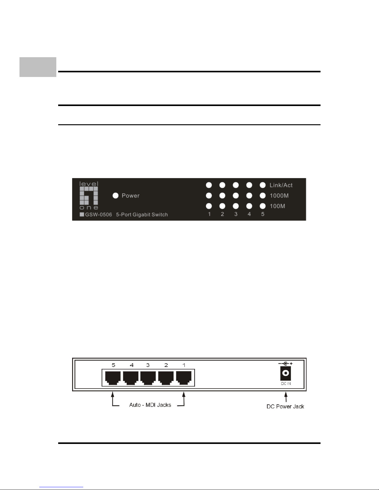
GSW-0506
Front Panel
The figure below shows the front panels of the switch.
Front panel view of the Switch
LED Indicators
Comprehensive LED indicators display the conditions of the
Switch and status of the network. A description of these LED
indicators follows (see LED Indicators).
Rear Panel
The rear panel of the Switch consists of an DC power connector.
The following figure shows the rear panel of the Switch.
Rear panel view of the Switch
English
Page 11

7
DC Power Jack:
Power is supplied through an external AC power adapter. Check
the technical specification section for information about the AC
power input voltage.
1000BASE-T Ports:
Five Gigabit Ethernet ports of 10/100/1000Mbps AutoNegotiation interface.
LED Indicators
The LED indicators of the Switch include Power, Link/Act,
1000Mbps and 100Mbps. The following shows the LED
indicators for the Switch along with an explanation of each
indicator.
Power
This indicator lights green when the Switch is receiving power,
otherwise, it is off.
Link/Act
These LED indicators are lighted up when there is a secure
connection (or link) to the desired port. The LED indicators
blinking whenever there is reception or transmission (i.e.
Activity—Act) of data occurring at a port.
1000M
These LED indicators are lighted up when there is a secure
connection (or link) to 1000Mbps Gigabit Ethernet device at
the desired port.
100M
These LED indicators are lighted up when there is a secure
connection (or link) to 100Mbps Fast Ethernet device at the
desired port.
English
Page 12
8
When the connection (or link) is 10Mbps, both of
1000Mbps and 100Mbps LED indicators are off.
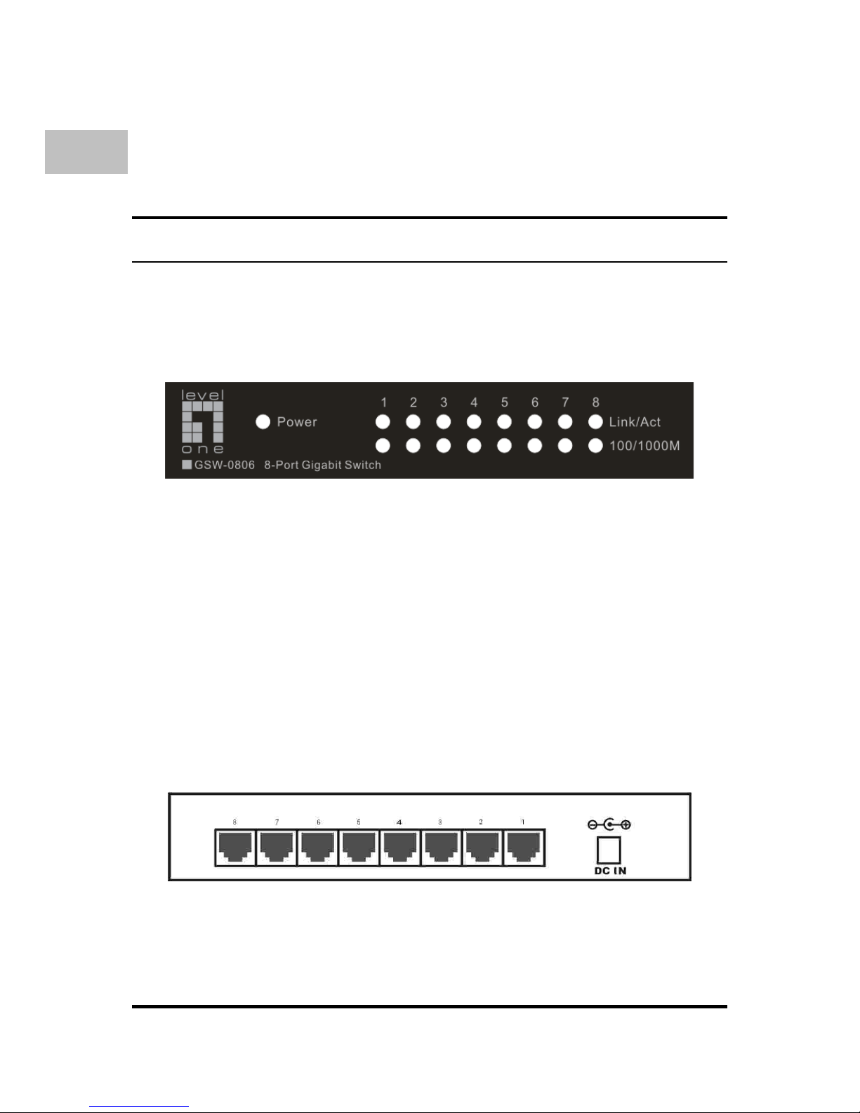
GSW-0806
Front Panel
The figure below shows the front panels of the switch.
Front panel view of the Switch
LED Indicators
Comprehensive LED indicators display the conditions of the
Switch and status of the network. A description of these LED
indicators follows (see LED Indicators).
Rear Panel
The rear panel of the Switch consists of an DC power connector.
The following figure shows the rear panel of the Switch.
Rear panel view of the Switch
English
Page 13

9
DC Power Jack:
Power is supplied through an external AC power adapter. Check
the technical specification section for information about the AC
power input voltage.
1000BASE-T Ports:
Eight Gigabit Ethernet ports of 10/100/1000Mbps AutoNegotiation interface.
LED Indicators
The LED indicators of the Switch include Power, Link/Act,
1000Mbps and 100Mbps. The following shows the LED
indicators for the Switch along with an explanation of each
indicator.
Power
This indicator lights green when the Switch is receiving power,
otherwise, it is off.
Link/Act
These LED indicators are lighted up when there is a secure
connection (or link) to the desired port. The LED indicators
blinking whenever there is reception or transmission (i.e.
Activity—Act) of data occurring at a port.
100/1000M
These LED indicators are lighted up in green when there is a
secure connection (or link) to 1000Mbps Gigabit Ethernet
device at the desired port. These LED indicators are lighted
up in amber when there is a secure connection (or link) to
100Mbps Fast Ethernet device at the desired port.
When the connection (or link) is 10Mbps, the
10/1000Mbps LED indicator is off.
English
Page 14
10
T
ECHNICAL SPECIFICATIONS
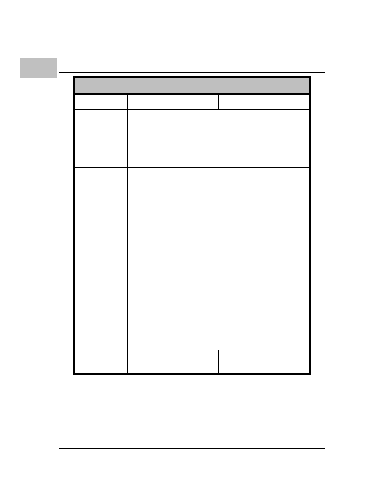
General
Model: GSW-0506 GSW-0806
Standards: IEEE 802.3ab 1000BASE-T
IEEE 802.3u 100BASE-TX
IEEE 802.3 10BASE-T
IEEE 802.3x Flow Control
Protocol: CSMA/CD
Data
Transfer
Rate:
10Mbps (Half-duplex) Ethernet:
20Mbps (Full-duplex)
100Mbps (Half-duplex) Fast Ethernet:
200Mbps (Full-duplex)
Gigabit
Ethernet:
2000Mbps (Full-duplex)
Topology: Star
Network
Cables:
Ethernet: 2-pair UTP Cat. 3,4,5, Unshield
Twisted Pair (UTP )Cable
Fast Ethernet: 2-pair UTP Cat. 5,
Unshield Twisted Pair (UTP )Cable
Gigabit
Ethernet:
4-pair UTP Cat. 5,
Unshield Twisted Pair (UTP )Cable
Number of
Ports:
5 Gigabit Ethernet ports 8 Gigabit Ethernet ports
English
Page 15
11
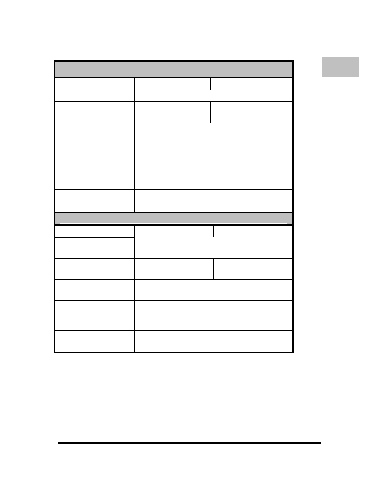
Physical and Environmental
Model: GSW-0506 GSW-0806
DC inputs: 7.5V 1A
Power
Consumption:
5 watts maximum 7.5 watts maximum
Operating
Temperature:
0 °C ~ 40°C
Storage
Temperature:
-10°C ~ 70°C
Humidity: 5% ~ 95% RH, non-condensing
Dimensions: 175 x 104 x 33 mm (W x H x D)
Certification:
FCC Class B, CE Marking Class B,
Performance
Model: GSW-0506 GSW-0806
Transmission
Method:
Store-and-forward
RAM Buffer: 112KBytes per
device
144KBytes per
device
Filtering Address
Table:
8K MAC address per device
Packet
Filtering/Forwardin
g Rate:
Full wire speed
MAC Address
Learning:
Self-learning, auto-aging
English
Page 16

12
Page 17

13
Ü
BER DIESE ANLEITUNG
Diese Anleitung wird ihnen erklären, wir Sie ihren
GSW-
0506/0806
5/8-Port Gigabit Switch, mit ihrem Gigabit
Ethernet Netzwerk verbinden.
Deutsch
Page 18

14
E
INLEITUNG
Features
Der Swtich wurde für eine einfache Installation und hohe
Performance konzipiert. 5/8-port 10/100/1000 Mbps
Gigabit Switch
Entspricht IEEE 802.3, 802.3u,802.3ab und
802.3x
Auto-MDIX an allen Ports
10/16 Gbps back-plane
N-Way Auto-Negotiation
Back pressure Half Duplex
Flow Control Full Duplex
Store-and-Forward Switching Achitektur
Deutsch
Page 19

15
A
USPACKEN UND EINRICHTEN
Dieses Kapitel enthält Information zum Lieferumfang und
Anschliessen des Switches.
Packungsinhalt
Dieses Packet sollte folgende Gegenstände enthalten:
Einen Gigabit Switch
Vier Gummifüße
Ein externes NetzteilOne external power adapter
Diese Anleitung
Falls ein Teil fehlen sollte oder beschädigt ist kontaktieren Sie
bitte ihren Händler.
Einrichtung
Die Einrichtungs des Switches geschieht mit folgenden
Schritten:
Installieren Sie den Switch an einen trockenen und kühlen
Platz.
Installieren Sie den Switch in eine Umgebung ohne starke
elektromagenetischen Quellen, Vibrationen, Staub und
direkten Sonnenlicht.
Es sollten 10cm Abstand nach Links und Rechts gehalten
werden, um die Belüftungs des Switches nicht zu stören.
Suchen Sie den DC Stromanschluß und stellen Sie sicher,
dass das Netzteil angeschlossen ist.
Deutsch
Page 20
16
Dieses Kapitel beschreib die Vorder- und Rückseite und die
LED Anzeigen des Switches
GSW-0506
Vorderseite
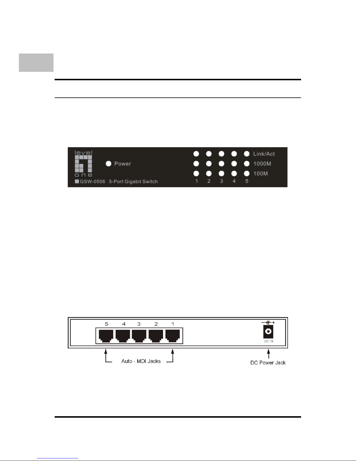
Diese Abbildung zeigt die Vorderseite des Switches.
Vorderansicht des Switches
LED Anzeigen
Mehrere LED Anzeigen, zeigen des Zustand des Switches und
den Status des Netzwerkes an. Eine Beschreibung der LED
folgt später.
Rückseite
Auf der Rückseite ist ein Gleichstromanschluß (DC). Die
folgende Abbildung zeigt die Rückseite des Switches.
Rückseite des Switches
DC Anschluß:
Deutsch
Page 21

17
Die Stromversorgung erfolgt durch ein externes Netzteil. Für die
technischen Spezifikationen schauen sie bitte im Anhang.
1000BASE-T Ports:
Fünf Gigabit Ethernet Port mit 10/100/1000Mbps
Auto.Negotiation Interface.
LED Anzeige
Die LED Anzeige des Switches beinhaltet Power, Link/Act,
1000Mbps und 100Mbps. Es folgt eine Erklärung der einzelnen
LEDs
Power
Diese Anzeige leuchtet grün, wenn der Switch Stom bekommt,
andernfalls ist sie aus.
Link/Act
Diese LED leuchtet, wenn eine Verbindung zum
entsprechenden Port hergestellt ist. Die LED blinkt, wenn
Daten auf diese Port empfangen oder gesendet werden..
1000M
Diese LED leuchtet, wenn eine 1000Mbps Verbindung an
dem entsprechenden Port hergestellt wurde.
100M
Diese LED leuchtet, wenn eine 100Mbps Verbindung an dem
entsprechenden Port hergestellt wurde-
Wenn die Verbindung nur mit 10Mbps hergestellt wird, sind die
1000Mbps und 100Mbps LEDs aus.
Deutsch
Page 22
18
GSW-0806
Vorderseite
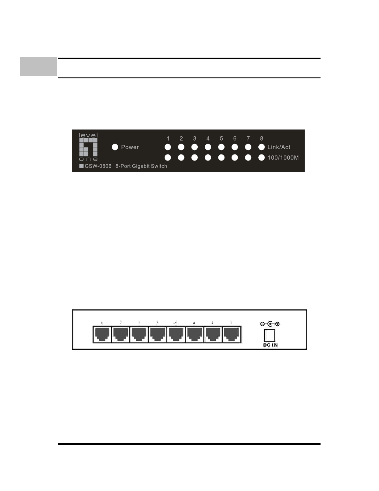
Diese Abbildung zeigt die Vorderseite des Switches.
Vorderansicht des Switches
LED Anzeigen
Mehrere LED Anzeigen, zeigen des Zustand des Switches und
den Status des Netzwerkes an. Eine Beschreibung der LED
folgt später.
Rückseite
Auf der Rückseite ist ein Gleichstromanschluß (DC). Die
folgende Abbildung zeigt die Rückseite des Switches.
Rückseite des Switches
DC Anschluß:
Die Stromversorgung erfolgt durch ein externes Netzteil. Für die
technischen Spezifikationen schauen sie bitte im Anhang.
1000BASE-T Ports:
Deutsch
Page 23

19
Fünf Gigabit Ethernet Port mit 10/100/1000Mbps
Auto.Negotiation Interface.
LED Anzeige
Die LED Anzeige des Switches beinhaltet Power, Link/Act,
1000Mbps und 100Mbps. Es folgt eine Erklärung der einzelnen
LEDs
Power
Diese Anzeige leuchtet grün, wenn der Switch Stom bekommt,
andernfalls ist sie aus.
Link/Act
Diese LED leuchtet, wenn eine Verbindung zum
entsprechenden Port hergestellt ist. Die LED blinkt, wenn
wenn Daten auf diese Port empfangen oder gesendet werden..
1000M
Diese LED leuchtet, wenn eine 1000Mbps Verbindung an
dem entsprechenden Port hergestellt wurde.
100M
Diese LED leuchtet, wenn eine 100Mbps Verbindung an dem
entsprechenden Port hergestellt wurde-
Wenn die Verbindung nur mit 10Mbps hergestellt wird, sind die
1000Mbps und 100Mbps LEDs aus.
Deutsch
 Loading...