

Page 1

1
GEU-1621
16-Port Gigabit Switch
V1. 0_20150424
Page 2

2
Table Of Contents
1. INTRODUCTION ......................................................... 3
1.1 Product Briefs ....................................................................................................... 3
1.2 Product Features.................................................................................................... 3
1.3 Hardware Introduction .......................................................................................... 4
2. CONNECTING THE SWITCH .................................... 5
2.1 Package Contents .................................................................................................. 5
2.2 Before You Connect to the Network ..................................................................... 6
2.3 Mounting ears for rack-mounting ......................................................................... 6
2.4 Attaching the Rubber Feet .................................................................................... 7
3. Connecting the switch ................................................... 8
3.1 Switch to End Node or Server .............................................................................. 8
3.2 Switch to Hub or Switch ....................................................................................... 9
4. Appendix ....................................................................... 9
4.1 Technical Specifications ....................................................................................... 9
4.2 RJ-45 PIN SPECIFICATION ............................................................................. 11
Page 3

3
1. INTRODUCTION
1.1 Product Briefs
The switch is a un-management layer 2 10/100Mbps switch; it provide dedicated 10,
100 ,1000Mbps Ethernet bandwidth on each port. The ports will automatically detect the
speed, duplex and MDI/MDIX status of the device it is connecting to, and adjust these
settings accordingly. The Switch ports can be used to network computers, printers, servers,
routers, other switches or any device equipped with an Ethernet port. For best performance,
use Category 5 or better Ethernet cabling.
This stand-alone Switch is very easy to set up, there is no network management required. Just
power on the Switch and connect the cables. Keep in mind however that the standard rules of
Ethernet regarding cable length apply to this and all Ethernet devices. The length of an
Ethernet cable from one device to another cannot exceed 100 meters (or 300 feet).
1.2 Product Features
The Switches do not require any management. All Switches are designed for easy installation,
flexibility and high performance. Connect devices to the Switch as the scale and volume of
network traffic increases.
16 10/100/1000Mbps Gigabit ports
Auto-Negotiation for 10/100/1000Mbps and duplex mode
Auto-MDI/MDIX for each port
Supports Full/Half-duplex transfer mode for 10 and 100Mbps
Full wire speed reception and transmission
Store-and-Forward Switching method
Supports 8K absolute MAC addresses
16-Port Switch Supports 340KB RAM for data buffering
IEEE 802.3x flow control for Full-duplex
Back pressure flow control for Half-duplex
Gigabit Ethernet is an extension of IEEE 802.3 Ethernet utilizing the same packet structure,
format, and support for CSMA/CD protocol, full duplex, flow control, and management
objects, but with a tenfold increase in theoretical throughput over 100-Mbps Fast Ethernet
Page 4
4
and a hundredfold increase over 10-Mbps Ethernet. Since it is compatible with all 10-Mbps
and 100-Mbps Ethernet environments, Gigabit Ethernet provides a straightforward upgrade
without wasting a company’s existing investment in hardware, software and trained
personnel.
The increased speed and extra bandwidth offered by Gigabit Ethernet is essential to coping
with the network bottlenecks that frequently develop as computers and their bus speeds get
faster and more users use applications that generate more traffic. Upgrading key components,
such as your backbone and servers to Gigabit Ethernet can greatly improve network response
times as well as significantly speed up the traffic between your subnets.
1.3 Hardware Introduction
1.3.1 Product Appearance
1.Front Panel
The figure below shows the front panel of the Switch.
16-Port Gigabit Switch Front Panel
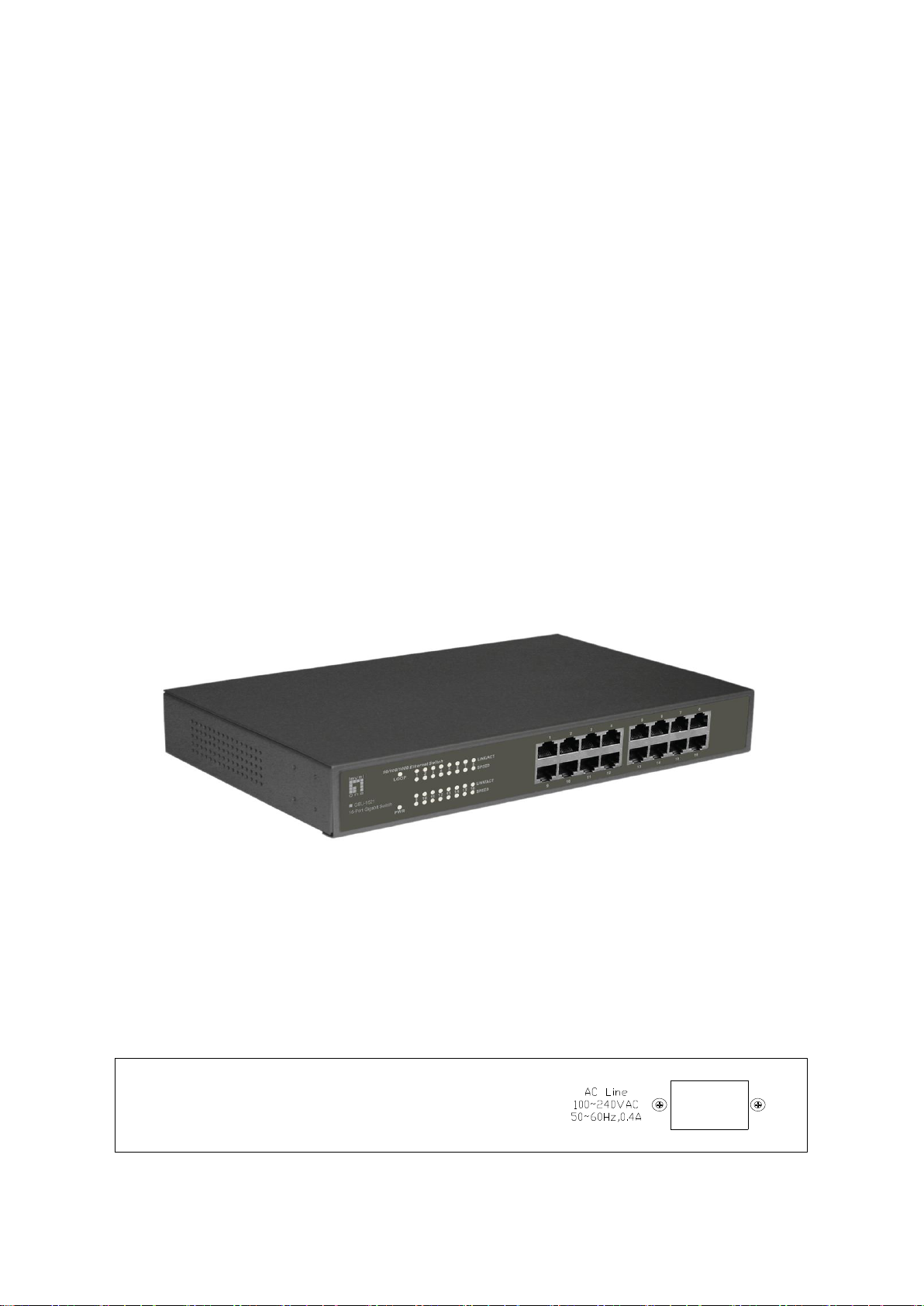
2.Rear Panel
The figure below shows the rear panel of the Switch. All MDI/MDI-X ports and an external
DC power adapter jack in the 16-port rear panel. There is a AC inlet in the 16-Port switch rear
panel.
16-Port Gigabit Switch Rear Panel
Page 5

5
LED
Panel
signature
Status
Description
Power
Indicator
Power
Green ON
Switch is powered ON
OFF
Switch is powered OFF
Speed
Indicator
Speed
Green ON
1000Mbit/s
OFF
10/100Mbit/s Link OR OFF
Status
Indicator
Link/Act
Green ON
Link
Green Blinking
Activity
OFF
No link path
Auto MDI/MDI-X Ports:
All ports support automatic MDI/MDI-X crossover detection. The AutoMDI/MDI-X function
makes it simple to connect to the switch—just plug either a Crossover or Straight-Through
CAT5 cable into any port.
DC Power Jack:
Power is supplied through an external DC power adapter. Check the technical specification
section for information about the DC power input voltage.
AC inlet
Power is supplied through external AC power. The input AC voltage is 100~240V.
1.3.2 LED Indicators
Table 1-3 Ethernet Switch LED Indicators
2. CONNECTING THE SWITCH
2.1 Package Contents
Open the shipping carton of the Switch and carefully unpack its contents.
The carton should contain the following items:
One 16-Port 10/100/1000BASE-T Gigabit Ethernet Switch
Four rubber feet with adhesive backing
One power Cord
Mounting ears for rack-mounting
CD-ROM with product documentation
Page 6

6
If any item is found missing or damaged, please contact your local reseller for replacement.
2.2 Before You Connect to the Network
The site where you install the Switch may greatly affect its performance. Please follow these
guidelines for setting up the Switch.
Install the Switch on a sturdy, level surface that can support at least 3 kg (6.6 lbs) of
weight. Do not place heavy objects on the Switch.
The power outlet should be within 1.82 meters (6 feet) of the Switch.
Visually inspect the power cord and see that it is fully secured to the AC power port.
Make sure that there is adequate space for proper heat dissipation from and adequate
ventilation around the Switch. Leave at least 10 cm (4 inches) of space at the front and
rear of the Switch for ventilation.
Install the Switch in a fairly cool and dry place for the acceptable temperature and
humidity operating ranges.
Install the Switch in a site free from strong electromagnetic field generators (such as
motors), vibration, dust, and direct exposure to sunlight.
When installing the Switch on a level surface, attach the rubber feet to the bottom of the
device. The rubber feet cushion the Switch, protect the casing from scratches and prevent
it from scratching other surfaces.
2.3 Mounting ears for rack-mounting
The 16-Port Gigabit Switch can easily be mounted on a rack. Two mounting ears are
provided for this purpose. Make sure that the front panel is exposed in order to view the
LEDs. Please refer to the following illustrations:
Page 7

7
Mounting the Switch to a Rack
1. Attach the ears to each side of the Switch, using the screw-holes located on the side of the
device.
2. Firmly attach the ears to the rack as shown. Please follow the usual safety precautions for
rack-mountable products.
2.4 Attaching the Rubber Feet
Use rubber feet provided. Position and apply rubber feet to the underside of the 16-Port
Gigabit Switch.
Page 8

8
Attaching the Rubber Feet
NOTE: UTP (Unshielded Twisted Pair) Ethernet cabling is adequate for
most small office environments. More expensive STP (Shielded Twisted
Pair) can also be used, but is generally only needed where there will be
risk of strong Electromagnetic of Radio Frequency Interference.
3. Connecting the switch
Cable Quality
For all connections to the Switch, use these rules to determine the Cable quality.
For connections to 10BASE-T and 100BASE-TX devices, use Category 5 or 5e
UTP/STP cable.
3.1 Switch to End Node or Server
End nodes include PCs outfitted with a 10, 100 Mbps RJ-45 Ethernet/Fast Ethernet
Network Interface Card (NIC) and Ethernet ready routers. Use standard Ethernet cable to
connect the Switch to end nodes. Switch ports will automatically adjust to the hardware
characteristics (MDI-II/MDI-X, speed, duplex) of the device to which it is connected. Switch
connected to an end node
Page 9

9
General
Standards:
IEEE 802.3u 100BASE-TX
IEEE 802.3 10BASE-T
IEEE 802.3x Flow Control
IEEE 802.1p
Protocol:
CSMA/CD
Data Transfer Rate:
Ethernet:
10Mbps (Half-duplex)
3.2 Switch to Hub or Switch
Connect to another switch or hub
4. Appendix
4.1 Technical Specifications
Table 4-1 Ethernet Switch General Features
Page 10

10
20Mbps (Full-duplex)
Fast Ethernet:
100Mbps (Half-duplex)
200Mbps (Full-duplex)
Gigabit Ethernet:
2000 Mbps (Full-duplex)
Topology:
Star
Network Cables:
Ethernet:
2-pair UTP Cat. 3,4,5, Unshield Twisted Pair (UTP )Cable
Fast Ethernet:
2-pair UTP Cat. 5, Unshield Twisted Pair (UTP )Cable
Gigabit Ethernet:
4-pair UTP Cat. 5, Unshield Twisted Pair (UTP )Cable
Number of Ports:
16
Physical and Environmental
AC Inputs(For 16-Port):
100~240VAC; 50~60HZ
Power Consumption
16-Port: 8 watts maximum
Operating Temperature
0 C ~ 40℃
Storage Temperature:
-10C ~ 70C
Storage:
5% ~ 95% RH, non-condensing
Operating:
10%~90% non-condensing
Dimensions:
16-Port: 280mm x 180mm x 44mm
EMI
FCC Class A, CE Mark Class A
Safety:
CSA International
Performance
Transmission Method:
Store-and-forward
RAM Buffer:
16-Port : 340KB
Filtering Address Table:
8K MAC address per device
Packet Filtering/ Forwarding
Rate:
Full wire speed
Table 4-2 Ethernet Switch Physical and Environmental Features
Table 4-3 Ethernet Switch Performance Features
Page 11

11
MAC Address Learning:
Self-learning, auto-aging
RJ-45 Connector pin assignment
Contact
Media Direct Interface Signal
1
TX_D1+
2
TX_D1-
3
RX_D2+
4
BI_D3+
5
BI_D3-
6
RX_D2-
7
BI_D4+
8
BI_D4-
4.2 RJ-45 PIN SPECIFICATION
The following diagram and tables show the standard RJ-45 receptacle/connector and their pin
assignments.
Standard RJ-45 receptacle/connector
 Loading...