

Page 1

LevelOne
FSW-0800FXC
FSW-0800FXT
FSW-1600FXC
FSW-1600FXT
8/16 Port 100Mbps Fast Ethernet Switch with
SC/ST Connector
User’s Guide
Page 2

Caution
Circuit devices are sensitive to static electricity, which can damage their delicate
electronics. Dry weather conditions or walking across a carpeted floor may cause
you to acquire a static electrical charge.
To protect your device, always:
• Touch the metal chassis of your computer to ground the static electrical
charge before you pick up the circuit device.
• Pick up the device by holding it on the left and right edges only.
Electronic Emission Notices
Federal Communications Commission (FCC) Statement
This equipment has been tested and found to comply with the limits for a class A
computing device pursuant to Subpart J of part 15 of FCC Rules, which are
designed to provide reasonable protection against such interference when
operated in a commercial environment
European Community (CE) Electromagnetic Compatibility Directive
This equipment has been tested and found to comply with the protection
requirements of European Emission Standard EN55022/EN60555-2 and the
Generic European Immunity Standard EN50082-1 that calls up the following basic
standards:
a) IEC801-2 Electrostatic Discharge
b) IEC801-3 RF Immunity
c) IEC801-4 Transient Burst
Page 3

Contents
Caution .............................................................................................................. I
Electronic Emission Notices............................................................................... I
Chapter 1 Introduction ..................................................................... 1-1
Overview .................................................................................................... 1-1
Model Description ...................................................................................... 1-1
Checklist .................................................................................................... 1-1
Front Panel................................................................................................. 1-2
Chapter 2
Installation ..................................................................................................2-1
Network Parameter for 100Mbps Fiber....................................................... 2-1
Switch Hub Cascading and Long Haul Connection .................................... 2-2
Fiber Port Full/Half-duplex DIP Switch Setup ............................................. 2-3
LED Indicators............................................................................................ 2-4
Chapter 3 Troubleshooting............................................................... 3-1
Cabling Problems .......................................................................................3-1
Workstation Problems ................................................................................ 3-2
Other Problems ......................................................................................... 3-2
Appendix.............................................................................................. A-1
Technical Specifications ............................................................................. A-1
Installing & Network Connection................................... 2-1
Page 4
1-1
Chapter 1
Introduction
Overview
The Levelone 8/16 Port Fiber Switch is a standard switch that meets all IEEE
802.3u/802.3x specifications. Fast Ethernet Switch is a cost-effective solution for
easing your network congestion problem on existing shared-hub network by
breaking up the collision domain and by multiplying the network performance. The
overall network transmission speed is increased and the network efficiency is
improved to accommodate high-bandwidth applications, such as imaging,
multimedia, and CAD/CAM, etc.. Four models are available:
FSW-0800FXC
FSW-0800FXT
FSW-1600FXC 16 Port 100Mbps Fast Ethernet Switch with SC Connector
FSW-1600FXT 16 Port 100Mbps Fast Ethernet Switch with ST Connector
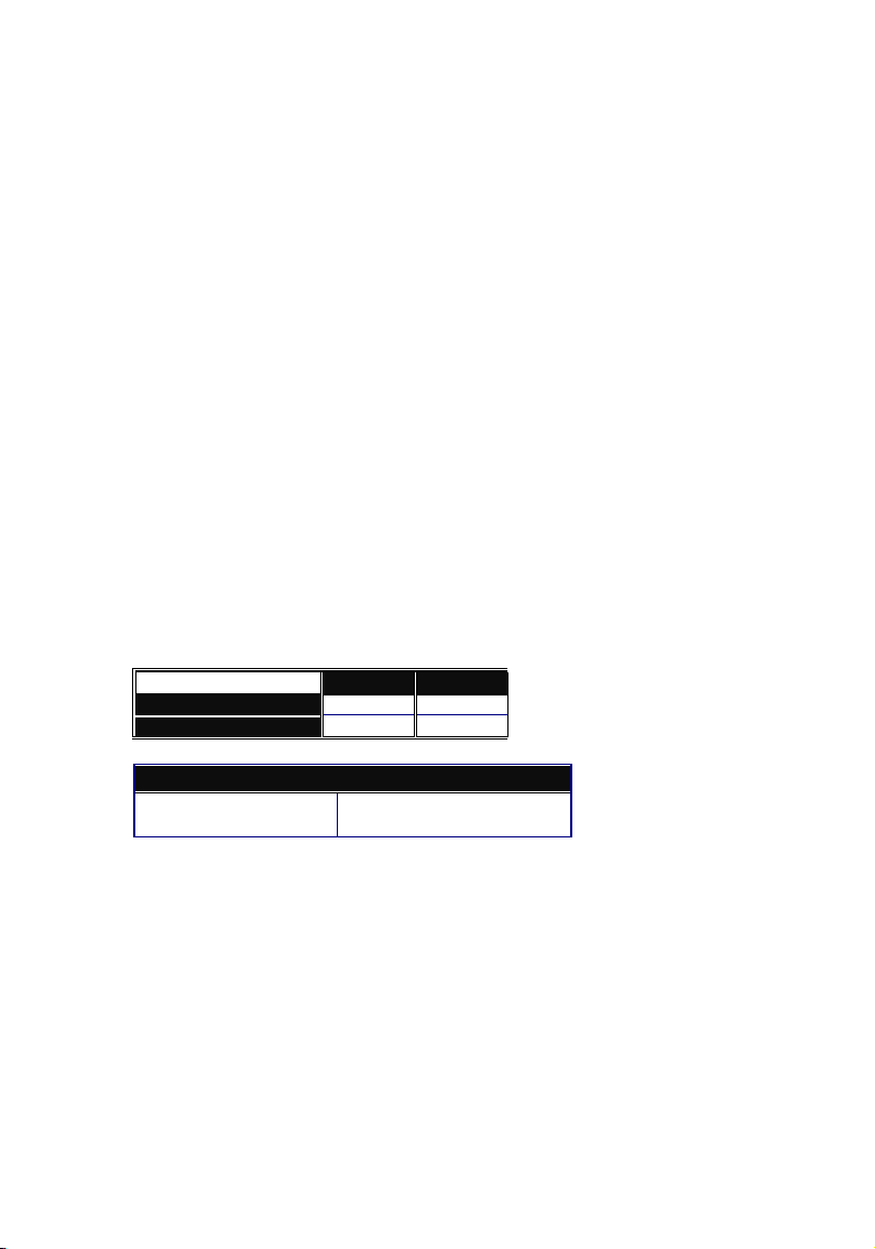
Models Description
Configuration 16 Fiber 8 Fiber
100FX Fiber Jack
10/100Mbps TP Jack
8 Port 100Mbps Fast Ethernet Switch with SC Connector
8 Port 100Mbps Fast Ethernet Switch with ST Connector
16 8
None None
The available Fiber Transceiver(Jack) for switch:
SC/ST multi-mode
SC single-mode
Default
optional
Checklist
Before you start installing the Fiber Switch, verify that the package contains the
following items:
¾ 1 LevelOne 8/16 Port 10/100Mbps Fast Ethernet Switch
¾ Mounting Accessory (for 19" Rack Shelf)
¾ AC Power Cord
¾ This User’s Manual
Please notify your sales representative immediately if any of the aforementioned
items is missing or damaged.
.
Page 5
2-1
Chapter 2
Installing & Network Connection
Installation
Þ
The fiber TX, RX cables must be paired at both ends.
Þ
Repeat the above step, as needed, for each fiber port to be connected to
a 100Base-FX device.
The fiber port can be up-linked to an upper level hub's port.
Þ
Þ Verify that the voltage of AC power is correct and plug in AC power cord.
Note:
1. Both local and remote link devices (mode) must operate at the same
transmission mode and speed
After the hub is powered off, wait at least 10 seconds before powering it
on again
Network Parameter for 100Mbps Fiber
To help ensure a successful installation, you must observe the following cabling
parameter. Violating these rules can render the LAN to work poorly.
Þ 100Base-FX fiber network connection
Full-duplex Switch via Fiber
Multi-mode
Half-duplex Switch via Fiber
Multi or single-mode
Half-duplex Class II Hub via Fiber
Multi or single-mode
Node to Node : 2km
Hub to Hub : 2km
Node to Hub : 2km
Node to Node : 15km
Node to Hub : 15kmSingle-mode
Hub to Hub : 15km
Node to Node : 412m
Node to Hub : 412m
Hub to Hub : 412m
Node to Node : 205m
Node to Hub : 100m
Hub to Hub : 5m
Page 6

3-1
Chapter 3
Troubleshooting
Network troubleshooting requires patience and logic. Generally speaking, the
cabling and workstation configurations are the likely first suspects; network
hardware is usually last on the list. The nature of the hub design dictates that it is
more likely for an entire hub to fail instead of just a single port.
Cabling Problems
Improper Cabling is the primary cause of most non-workstation problems on
Ethernet network, particularly for 100 Base-FX networks. It must be emphasized
that genuine twisted-pair cable and fiber optic cable be used to avoid many types
of cabling problems
• Wiring is definitely the problem if the Link LED does not light when the fiber
plug from a workstation is inserted into the port jack. Either correct the break
in the wire or replace the wire before proceeding
• Multi or single-mode fiber cable should match the switch's fiber transceiver.
• If a workstation (workstation A) does not work and other 100Base-X ports on
the hub are functioning, remove a fiber plug from a functioning port with a
functioning workstation (workstation B) and insert it into the suspect port. If
workstation B still works, the problem is in workstation A or in the wiring.
However, if workstation B does not work, then the hub may have a defective
port. Even if you suspect a defective port on the hub, continue testing.
Improperly wired workstations may appear to be functional, especially if they
are located near the hub. Sometimes, a port connected to an improperly wired
workstation can function marginally while another port may not work at all
• Once you have established that the hub is working properly, check all wiring
between the hub and the malfunctioning workstation. Ensure that the transmit
and receive wires have not been crossed; the two transmit wires should be
paired together as should the two receive wires
• Use a continuity checker to ensure that wires do not have breaks. By shorting
together the two wires of a pair at one end, you can use the continuity checker
at the other end. Also, check that there are no shorts between wires
Page 7

16 Port Fiber Switch
Technical Specifications
Standards Compliance : IEEE802.3u and 802.3x 100Base-FX
Transmission Mode : Full or Half duplex
Transmission Speed : 100Mbps
Packet forwarding/filtering Rate:
148,800 packets / sec full wire rate on 100Mbps forwarding and filtering
MAC Address and Self-learning: up to 12K
Buffer Memory : 1024KB for 16 ports
Flow control : IEEE802.3x compliant for full-duplex
Back pressure flow control for half-duplex
Network Interface :
¾ 16ST.M : Sixteen ST multi-mode fiber ports
¾ 16SC.M : Sixteen SC multi-mode fiber ports
¾ 16SC.S : Sixteen SC single-mode fiber ports
Cable and Maximum length:
A-1
FX(Fiber)
Selectable Duplex Mode Switch: Per fiber port FDX/HDX DIP switch
Diagnostic LED:
System LED : Power
Per Port LED : Link/Act, 100Mbps, FDX/Col
Power Requirement : AC Line
Ambient Temperature : 0° to 50°C
Humidity : 5% to 90%
Dimensions : 44(H) ´ 440(W) ´ 200(D) mm
Complies with FCC Part 15 Class A & CE Mark Approval
50/125, 62.5/125 or 100/140mm multi-mode, up to 2Km
8.3/125, 8.7/125, 9/125 or 10/125mm single-mode, up to 15Km
Voltage : 100~240 V
Frequency : 50~60 Hz
Consumption : 65W Max.
Page 8

8 Port Fiber Switch
Technical Specifications
Standards Compliance : IEEE802.3u and 802.3x 100Base-FX
Transmission Mode : Full or Half duplex
Transmission Speed : 100Mbps
Packet forwarding/filtering Rate:
148,800 packets / sec full wire rate on 100Mbps forwarding and filtering
MAC Address and Self-learning: up to 12K
Buffer Memory : 1024KB for 8 ports
Flow control : IEEE802.3x compliant for full-duplex
Back pressure flow control for half-duplex
Network Interface :
¾ 8ST.M : Eight ST multi-mode fiber ports
¾ 8SC.M : Eight SC multi-mode fiber ports
¾ 8SC.S : Eight SC single-mode fiber ports
Cable and Maximum length:
A-2
FX(Fiber)
Selectable Duplex Mode Switch: Per fiber port FDX/HDX DIP switch
Diagnostic LED:
System LED : Power
Per Port LED : Link/Act, 100Mbps, FDX/Col
Power Requirement : AC Line
Ambient Temperature : 0° to 50°C
Humidity : 5% to 90%
Dimensions : 44(H) ´ 440(W) ´ 200(D) mm
Complies with FCC Part 15 Class A & CE Mark Approval
50/125, 62.5/125 or 100/140mm multi-mode, up to 2Km
8.3/125, 8.7/125, 9/125 or 10/125mm single-mode, up to 15Km
Voltage : 100~240 V
Frequency : 50~60 Hz
Consumption : 43W Max.
Page 9

3-2
Workstation Problems
Most non-cabling problems result from improper configuration of the network
interface card (NIC) and its corresponding driver. The following points will be
helpful:
• Like other add-on cards in the workstation or server, NIC must have unique
memory address, I/O address, and interrupt. The settings on a particular card
must not conflict with the settings on any other card in the same station.
Please refer the User's manual of the NIC, computers, and Networking
operating systems to determine the proper configuration
• The selection of half or full duplex, the speed of 10 or 100Mbps for the NIC
setting must match the mode and speed setting of the corresponding port of
the Hub. For NWay Auto-Negotiation setting, both link partners will auto-adjust
to the highest allowable speed and mode operation
Other Problems
Other specific problems may be diagnosed by using the LEDs, as below.
Power LED is off when the AC Power switch is ON:
• Defective power supply unit or fuse
• Incorrect AC voltage
• Defective Hub
Link/Act LED is off at any Fiber:
• Faulty node or wiring connection
For fiber - the "TX", "RX" cables should be paired at both ends
No Link signal is received from the remote node/site
100Base-X Port at irregular traffic:
• Abnormal or invalid transmission status(mode / speed) between local and
remote link partners, i.e., full-duplex port is connecting to a half-duplex port,
or 10Mbps port is connecting to a 100Mbps device
Hub Diagnostic Test
The switch hub performs self-diagnostic test at major hub modules upon
power on, LED indicators will go to normal status if no problem occurred
To reset or restart the hub, power off the hub and wait for 10 seconds, then
power on it again
Page 10

2-
2
For connection to Router, Bridge, or regular 100Base-X Hub, please refer to the
device’s Technical Manual for respective bit-time delay.
Switch Hub Cascading and Long-Haul Connection
Theoretically, the switch hub breaks up the collision domain in hub cascading that
you may up-link the hubs unlimitedly. In practice, the network extension
(cascading levels & overall diameter) is limited by the timing requirement--time-out
specification--of your application software and network operating system.
A hierarchical network with minimum levels of hub may reduce the timing delay
between server and client station. If more than two hubs are connected in the
same room, select one hub as Level 1 hub and connect all other hubs to it at Level
2. Server/Host is recommended to connect to the Level 1 hub. By following this
approach, it will minimize the number of hubs in any one path and will improve
network efficiency. (See Fig. 2-1)
The fiber switch(single mode transceiver) with single mode fiber can provide the
long haul connection up to 15km per segment, you may extend the distance by
cascading the switch and meet the timing requirement of your application
software. Sum up all elements’ bit-time delay and the overall bit-time delay of
wires/devices must be within 512 bit in a 100Base-X network segment (collision
domain). The fiber cables and devices’ bit-time delay(round trip) is as below:
100Base-TX 100Base-FX
DTE«DTE:
100
DTE«DTE:
100
Class II Hub: 92 Class II Hub: 92
Cat. 5 TP Wire: 1.112/m Fiber Cable: 1.0/m
DTE FX to DTE TX :100
100Base-TX to 100Base-FX Converter: 56
Page 11

Level 2 8 port Fiber Switch
Level 2 16 Port Fiber ST/SC Switch
Level 1
16 Port 100Mbps Fast Ethernet Switch with SC Connector
8 Port 100Mbps Fast Ethernet Switch with SC Connector
16 Port 100Mbps Fast Ethernet Switch with SC Connector
Fig. 2-1 Multiple Hubs Cascading and Long-Haul Connection
1 2 3 4 5 6 7 8
TX RX
9 10 11 12 13 14 15 16
TX RX TX RXTX RX TX RX
TX RX
TX RX
TX RX
Long Haul Intra-hub connection
1 2 3 4 5 6 7 8
TX RX
TX RX
1 2 3 4 5 6 7 8
TX RX
9 10 11 12 13 14 15 16
TX RX TX RXTX RX TX RXTX RX TX RX
TX RX TX RXTX RX TX RX
TX RX
TX RX
TX RX
2-3
Every fiber port is FDX/HDX selectable by DIP switches, the default setting is
FDX. You may force each fiber port into either
between local and remote fiber devices are:
Local Fiber Port Remote Fiber Port
Full-duplex Full-duplex
Half-duplex Half-duplex
FDX
HDX
Note:
¾ The dark block denotes the switch position that each bit should be set to
respectively.
¾ To alter the duplex mode, power down the hub and select the DIP switch
FDX or HDX. Two typical modes
21 4 5 6 7
3
8
(Default)
Page 12

2-4
mode setting. Then, power on to restart the new configuration and status.
Page 13

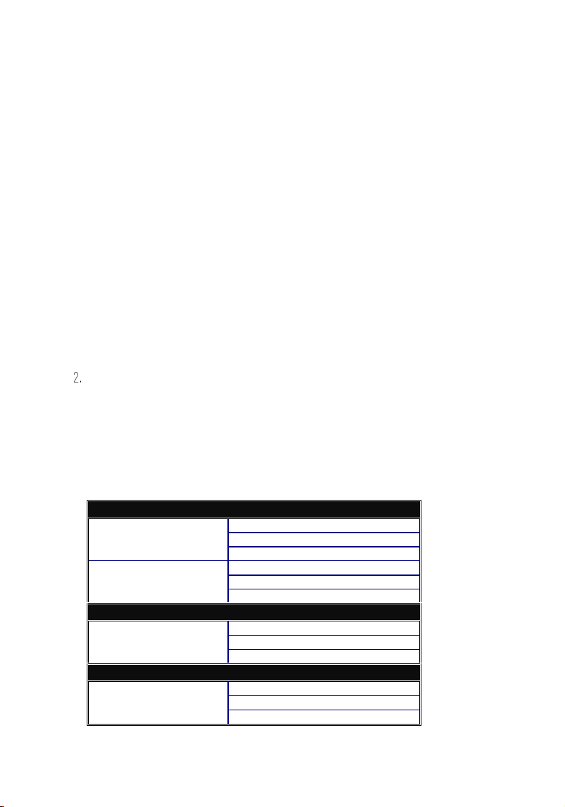
LED Indicators
The status and descriptions of LED indicators are listed as below:
PWR
8 Port 100Mbps Fast Ethernet Switch with SC Connector
LED Color Function
System LED
PWR Green Lit when AC power is on and good
Per Port LED
Link/Act Green
100Mbps Green Lit when 100Mbps speed is active
FDX/Col Amber
Lit when connection with remote device is good
Blinks when any traffic is present
Lit when full-duplex mode is active
Blinks when any collision signal is present
2-5
Table 2-1 LED indicators description and status
The 8/16 port switch LED indicators are the same as Table 2-1 except the port
capacity and associated LED indicators.
Page 14

1-2
1
4
5
6
7
8
3
9
1 2 3 4 5 6 7 8
1
4
5
6
7
8
3
1/MPR23456781/DTE
TX RX
TX RX
FDX
HDX
A B
A B
A
B
Link
100MFDC
POW
Link/
100MFDC
10/100 Switching
1234567
8
2
1
4
3
2
1
4
3
TX RX
TX RX
TX RX
TX RX
2
1
4
3
FDX
HDX
1
2
3
4
Link/Act
100Mbps
FDX/Col
1 2 3 4 5 678
Link/Act
100Mbps
FDX/Col
910111213141516
POWER
Fast Ethernet Switching Hub
1 2 3 4 5 6 7 8
Link/Act
100Mbps
FDX/Col
POWER
1 2 3 4 5 6 7 8 2
TX RX TX RX TX RX TX RX TX RX TX RX TX RX TX RX
9 10 11 12 13 14 15 16
Fig. 1-1 Front view of 16 Port ST/SC Fiber Switch
TX RXTX RXTX RXTX RXTX RXTX RXTX RXTX RX
Fig. 1-2 Front view of 8 Port ST/SC Fiber Switch
Fig. 1-3 Front view of 8 TP with 2 Fiber ST/SC Switch
Fast Ethernet Switching Hub
1 2 3 4
Link/Act
100Mbps
FDX/Col
POWER
Fig. 1-4 Front view of 4 Port Fiber ST/SC Switch
FDX
HDX
10111213141516
FDX
HDX
2
FDX
HDX
FDX
HDX
Fast Ethernet Switching Hub
1 2 3 4
Link/Act
100Mbps
FDX/Col
POWER
Fig. 1-5 Front view of 4 Port Fiber MT-RJ Switch
 Loading...