

LevelOne FCS-1151 User Manual
FCS-1151
2-Megapixel H.264 IP Camera
User’s Manual
V1.0

2 - User's Manual
Table of Contents
Overview.......................................................................................................................................................3
Read Before Use .....................................................................................................................................3
Package Contents ...................................................................................................................................3
Physical Description ................................................................................................................................4
Installation ....................................................................................................................................................6
Hardware Installation ...............................................................................................................................6
Network Deployment ...............................................................................................................................6
Software Installation ..............................................................................................................................10
Network Setting .....................................................................................................................................15
PPPoE Setting .......................................................................................................................................15
Accessing the Network Camera .................................................................................................................22
Using Web Browsers .............................................................................................................................22
Using RTSP Players ..............................................................................................................................24
Using 3GPP-compatible Mobile Devices ...............................................................................................25
Using LevelOne Recording Software .................................................................................................... 26
Main Page ..................................................................................................................................................27
Client Settings ............................................................................................................................................31
Conguration ..............................................................................................................................................33
System ..................................................................................................................................................34
Security .................................................................................................................................................36
HTTPS (Hypertext Transfer Protocol over SSL) ...................................................................................37
SNMP (Simple Network Management Protocol) .................................................................................. 42
Network ................................................................................................................................................. 43
DDNS .................................................................................................................................................... 58
Access List ........................................................................................................................................... 60
Audio and Video ....................................................................................................................................63
Motion Detection ...................................................................................................................................76
Camera Tampering Detection ...............................................................................................................79
Camera Control .....................................................................................................................................80
Homepage Layout ................................................................................................................................87
Application ............................................................................................................................................90
Recording ...........................................................................................................................................103
Local Storage ..................................................................................................................................... 106
System Log ........................................................................................................................................110
View Parameters ................................................................................................................................ 111
Maintenance ........................................................................................................................................ 112

User's Manual - 3
Overview
LevelOne FCS-1151 is a professional-series fixed network camera featuring superb image quality
and exceptional bandwidth efficiency. It is especially suitable for wide open spaces such as building
entrances and airports, or applications requiring accurate identication, such as human faces in banks or
vehicle license plates in parking lots.
Featuring a 2-megapixel sensor, this camera is able to provide a wide eld of view with exceptional detail
when compared to a standard VGA camera, signicantly reducing the number of camera installations.
The ePTZ function enables users to focus on close-up shots of different areas in the camera’s view
without moving the camera physically. Users can quickly move to a target area by simply clicking on
the video feed from the camera on their screen. In addition, the FCS-1151 can deliver user-defined
thumbnails for viewing instead of video of an entire scene so as to optimize bandwidth and storage
efciency.
The FCS-1151 supports H.264 compression technology, drastically reducing le sizes and conserving
valuable network bandwidth. With MPEG-4 and MJPEG compatibility, video streams can also be
transmitted in either of these formats for versatile applications. The streams can also be individually
configured to meet different needs or bandwidth constraints, thereby further reducing bandwidth and
storage requirements. Users can receive multiple streams simultaneously in different resolutions, frame
rates and image qualities for viewing on different platforms.
Thanks to its day and night function achieved by a built-in removable IR-cut lter, the FCS-1151 is able to
maintain clear images 24 hours a day.
Additionally, the FCS-1151 camera incorporates an adjustment ring to improve lens compatibility with
either C- or CS-mount lens, providing system integrators with more exibility and hassle-free installation
for different applications. The built-in SD/SDHC card slot offers a convenient and portable storage option
to prevent data loss in case of network disconnection.
Data security with the FCS-1151 is further enhanced with HTTPS encryption and 802.1x authentication.
Together with PoE, QoS, activity adaptive streaming, and the included 32-CH central management
software, the FCS-1151 is indisputably the top choice for reliable and high performance surveillance.
Read Before Use
The use of surveillance devices may be prohibited by law in your country. The Network Camera is not
only a high-performance web-ready camera but can also be part of a exible surveillance system. It is
the user’s responsibility to ensure that the operation of such devices is legal before installing this unit for
its intended use.
It is important to rst verify that all contents received are complete according to the Package Contents
listed below. Take note of the warnings in the Quick Installation Guide before the Network Camera is
installed; then carefully read and follow the instructions in the Installation chapter to avoid damage due to
faulty assembly and installation. This also ensures the product is used properly as intended.
The Network Camera is a network device and its use should be straightforward for those who have basic
networking knowledge. It is designed for various applications including video sharing, general security/
surveillance, etc. The Configuration chapter suggests ways to best utilize the Network Camera and
ensure proper operations. For creative and professional developers, the URL Commands of the Network
Camera section serves as a helpful reference to customizing existing homepages or integrating with the
current web server.
Package Contents
■ FCS-1151
■ Power Adapter
■ Camera Stand
■ CS-mount Lens
■ Software CD
■ Quick Installation Guide
■ L-type Hex Key Wrench

4 - User's Manual
Physical Description
General I/O Terminal Block
This Network Camera provides a general I/O terminal block which is used to connect external
input / output devices. The pin denitions are described below.
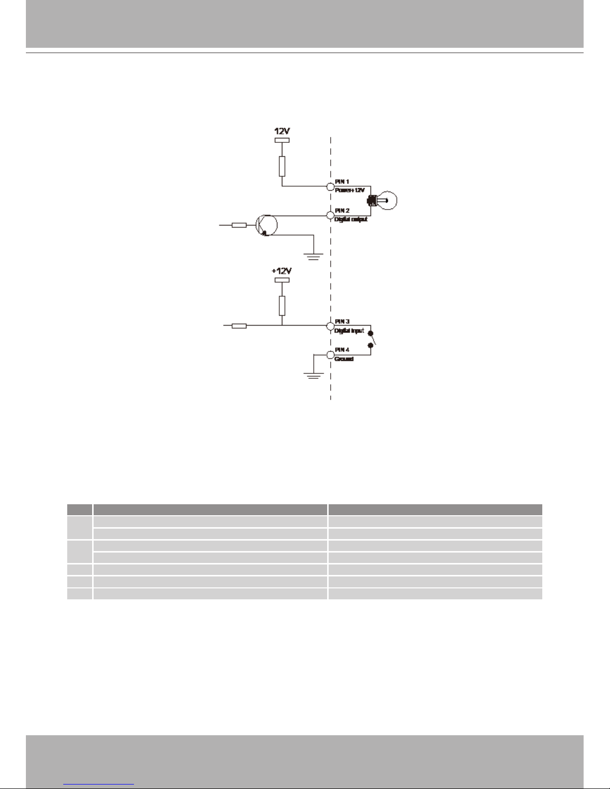
Pin Name
1 Power +12V
2 Digital Output
3 Digital Input
4 Ground
5 AC 24V input
6 AC 24V input
7 RS-485 +
8 RS-485 -
User's Manual - 5
DI/DO Diagram
Please refer to the following illustration for the connection method.
Status LED
The LED indicates the status of the Network Camera.
Item LED status Description
1
Steady Red Power on and system booting
Red LED unlighted Power off
2
Steady Red + Blink Green every 1 sec. Network works (heartbeat)
Steady Red + Green LED unlighted Network fail
3 Steady Red + Blink Green every 2 sec. Audio mute (heartbeat)
4 Blink Red every 0.15 sec. + Blink Green every 1 sec. Upgrading Firmware
5 Blink Red every 0.15 sec. + Blink Green every 0.15 sec. Restore default

6 - User's Manual
Hardware Reset
The reset button is used to reset the system or restore the factory default settings. Sometimes
resetting the system can return the camera to normal operation. If the system problems remain
after reset, restore the factory settings and install again.
Reset: Press and release the recessed reset button with a paper clip or thin object. Wait for the
Network Camera to reboot.
Restore: Press and hold the recessed reset button until the status LED rapidly blinks. It takes
about 30 seconds. Note that all settings will be restored to factory default. Upon successful
restore, the status LED will blink green and red during normal operation.
SD/SDHC Card Capacity
This network camera is compliant with SD/SDHC 16GB / 8GB and other preceding standard SD
cards.
Installation
Hardware Installation
Follow the steps below to mount the lens to the Network Camera:
1. Mount the lens by turning it clockwise onto the camera mount until it stops. If necessary, turn
the lens counterclockwise slowly until it gets the best attitude.
2. Connect the lens cable plug to the camera connector.
Network Deployment
Setting up the Network Camera over the Internet
This section explains how to congure the Network Camera to an Internet connection.
1. If you have external devices such as sensors and alarms, connect them to the general I/O
terminal block.
2. Connect the camera to a switch via Ethernet cable.
3. Connect the power cable from the Network Camera to a power outlet.
There are several ways to set up the Network Camera over the Internet. The rst way is to set
up the Network Camera behind a router. The second way is to utilize a static IP. The third way is
to use PPPoE.
There are several ways to set up the Network Camera over the Internet. The rst way is to set
up the Network Camera behind a router. The second way is to utilize a static IP. The third way is
to use PPPoE.
User's Manual - 7
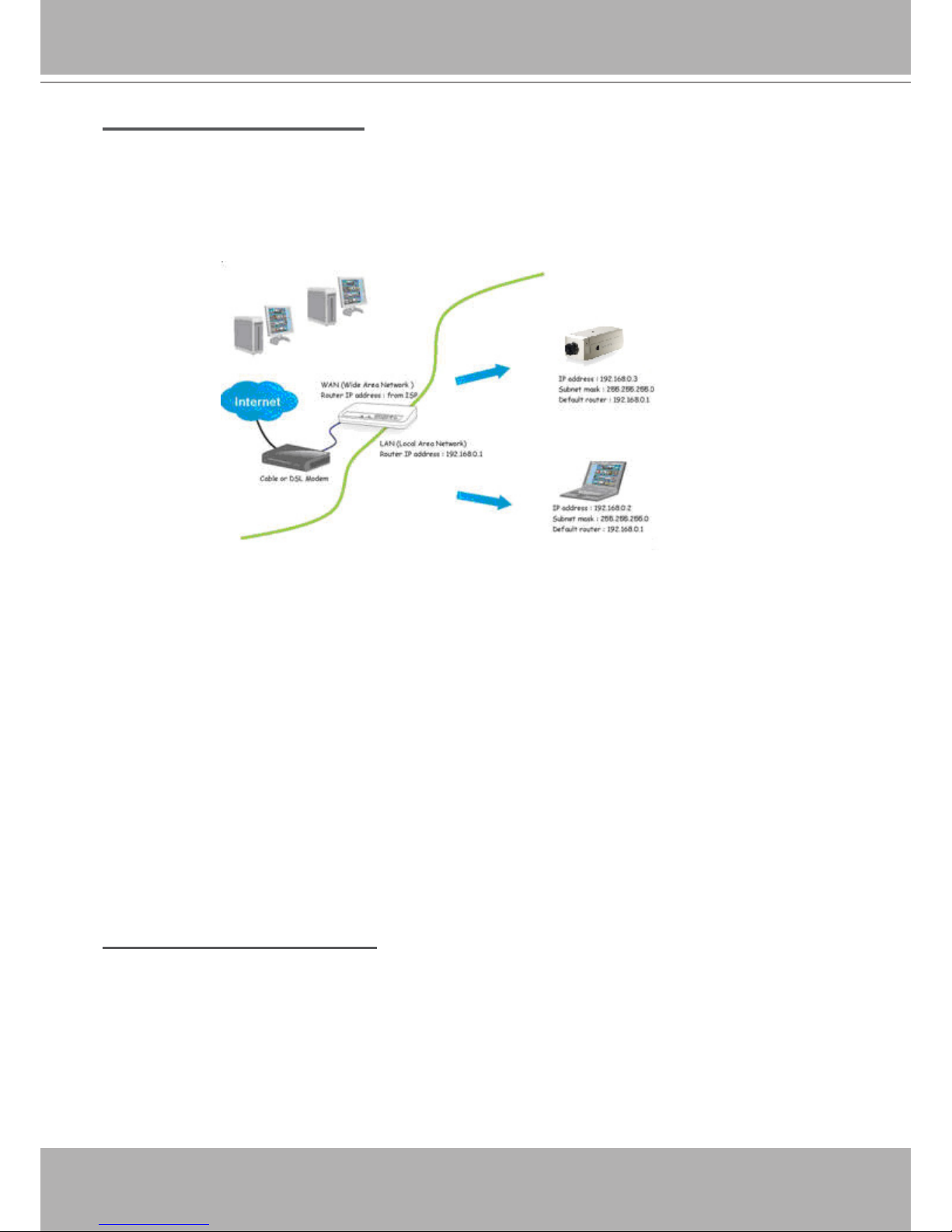
Internet connection via a router
Before setting up the Network Camera over the Internet, make sure you have a router and follow
the steps below.
1. Connect your Network Camera behind a router, the Internet environment is illustrated below.
Regarding how to obtain your IP address, please refer to Software Installation on page 10 for
details.
2. In this case, if the Local Area Network (LAN) IP address of your Network Camera is
192.168.0.3, please forward the following ports for the Network Camera on the router.
■ HTTP port
■ RTSP port
■ RTP port for audio
■ RTCP port for audio
■ RTP port for video
■ RTCP port for video
If you have changed the port numbers on the Network page, please open the ports accordingly
on your router. For information on how to forward ports on the router, please refer to your
router’s user’s manual.
3. Find out the public IP address of your router provided by your ISP (Internet Service Provider).
Use the public IP and the secondary HTTP port to access the Network Camera from the
Internet. Please refer to Network Type on page 33 for details.
Internet connection with static IP
Choose this connection type if you are required to use a static IP for the Network Camera.
Please refer to LAN for details.
1. Set up the Network Camera in a LAN. Please refer to Software installation on latter
pages for details.
2. Go to Conguration > Network > Network Type. Select LAN > Use xed IP address.
3. Enter the static IP, Subnet mask, Default router, Primary DNS provided by your ISP.
8 - User's Manual
Internet connection via PPPoE (Point-to-Point over Ethernet)
Choose this connection type if you are connected to the Internet via a DSL Line. Please refer to
PPPoE for details.
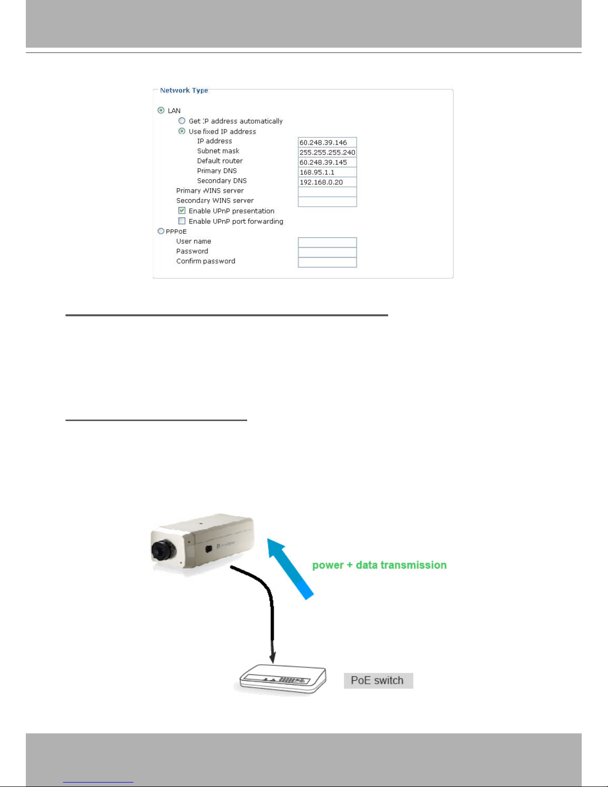
Set up the Network Camera through Power over Ethernet (PoE)
When using a PoE-enabled switch
The Network Camera is PoE-compliant, allowing transmission of power and data via a single
Ethernet cable. Follow the below illustration to connect the Network Camera to a PoE-enabled
switch via Ethernet cable.
User's Manual - 9
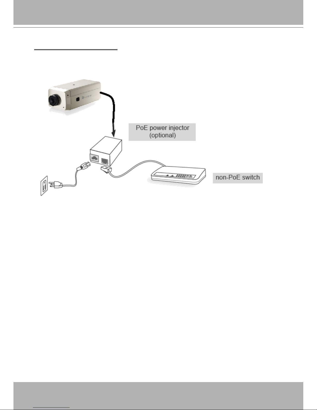
When using a non-PoE switch
If your switch/router does not support PoE, use a PoE power injector (optional) to connect
between the Network Camera and a non-PoE switch.
10 - User's Manual
Software Installation
The following are steps for the software installation.
Note: The default user name is root and the password is blank
How to Use Installation Wizard
Installation
The following are steps for the software installation.
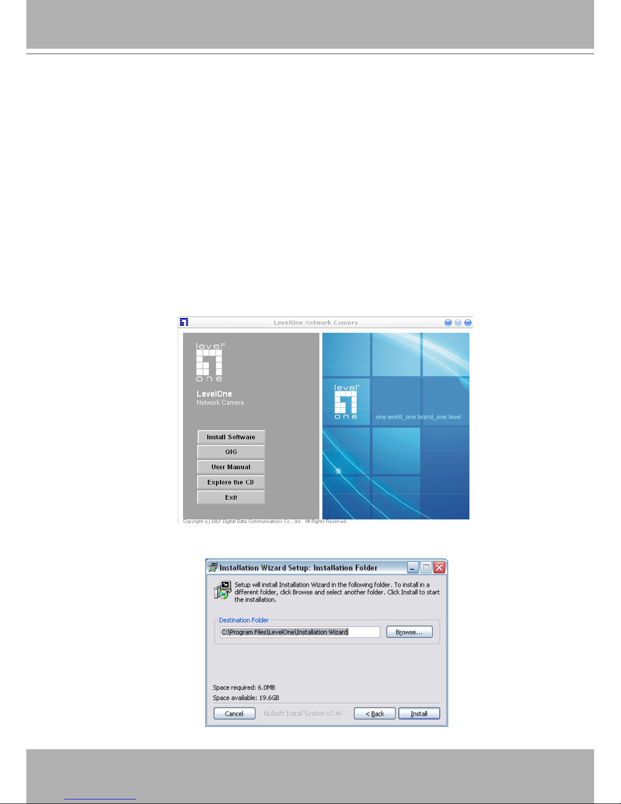
STEP. 1 Put the Installation disk into the CD-ROM drive, and the installation should start
automatically. If the installation does not start, click on “Start” on the lower left corner of your
screen, open “My Computer” and double click on the CD-ROM icon. The Installation Wizard
Installation Window will appear.
STEP. 2 There are links on this page, including Install Software, User’s Manual and Customer
Homepage. Click on “Install Software” to enter Install Software page.
STEP. 3 There are links on this page, including Installation Wizard, User’s Manual and
Surveillance Software. Click on “Installation Wizard” to launch the setup program.
Destination Location for Installation
User's Manual - 11
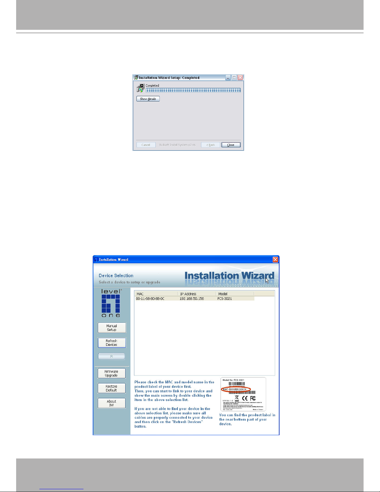
STEP 4: After clicking “Install” button, the install system will install the Installation Wizard to your
computer, and a progress bar will display on the dialog. After completed the installation, please
click on the “Close” button.
Completed
Using Installation Wizard
User Interface
Once you run the Installation Wizard, after a short searching time, you will see the user interface
as below. “Manual Setup” button, a “Refresh Devices” button and an arrow button on the left
panel of your user interface. When you click on the arrow button, you will see more advanced
functional buttons: “Firmware Upgrade”, “Restore Default” and “About IW”. You can select
your device by double-clicking it in the device list. The left three buttons (“Manual Setup”,
“Firmware Upgrade”, and “Restore Default”) won’t be enabled until you select at least one
device.
Installation Wizard allows you to setup one device at one time and upgrade multiple devices
(of the same model) at the same time. If you selected different models, then the “Firmware
Upgrade” button would be disabled.
12 - User's Manual
Installation wizard allows you to setup or upgrade multiple devices (of the same model) at the
same time. If you selected different models, then the buttons will be disabled. There are five
buttons on the bottom of the main page, and ve buttons on the left panel of the main page.
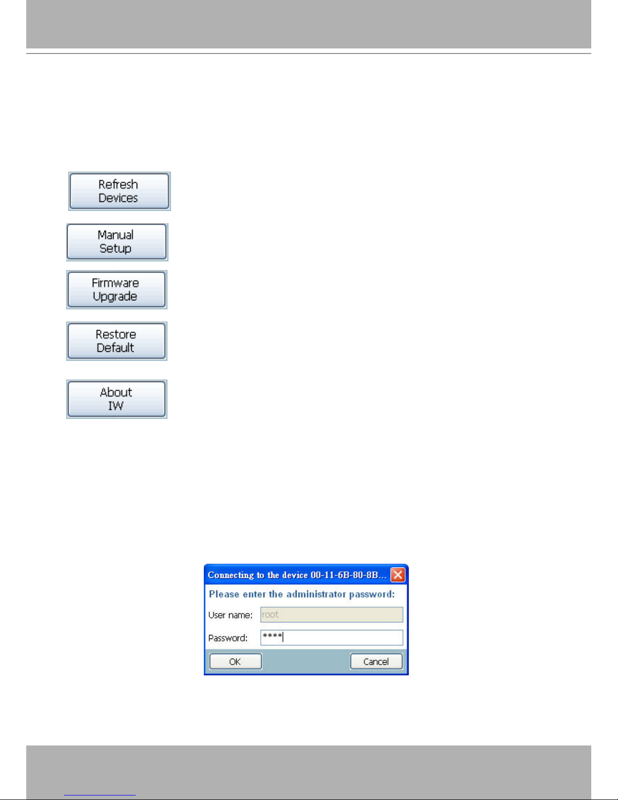
Buttons
Click on this button to clean up the device list and search all devices on
the within the same subnet again. It will take about 5 seconds.
Click on this button to modify the settings of the selected devices. For
more detail, please refer to 0 Setup.
Click on this button to upgrade the rmware of the selected devices. For
more detail, please refer to 0 Upgrade.
Click on this button to reset the selected devices to default settings.
Click on this button to get information about the Installation Wizard.
Manual Setup
When you select one device in the selection list, the “Manual Setup” button will be enabled.
Click on it to modify the settings of the selected device. After clicked on the “Manual Setup”
button, Installation Wizard would try to connect to the selected device.
The default Administrator’s password is blank and the Network Camera initially will not ask for
any password. If the authentication is failed, there would be a pop-up dialog window to ask for
correct password. If you failed three times, the Installation Wizard would show you a warning
dialog window and abort the connecting to the selected device.
Authentication Dialog Window
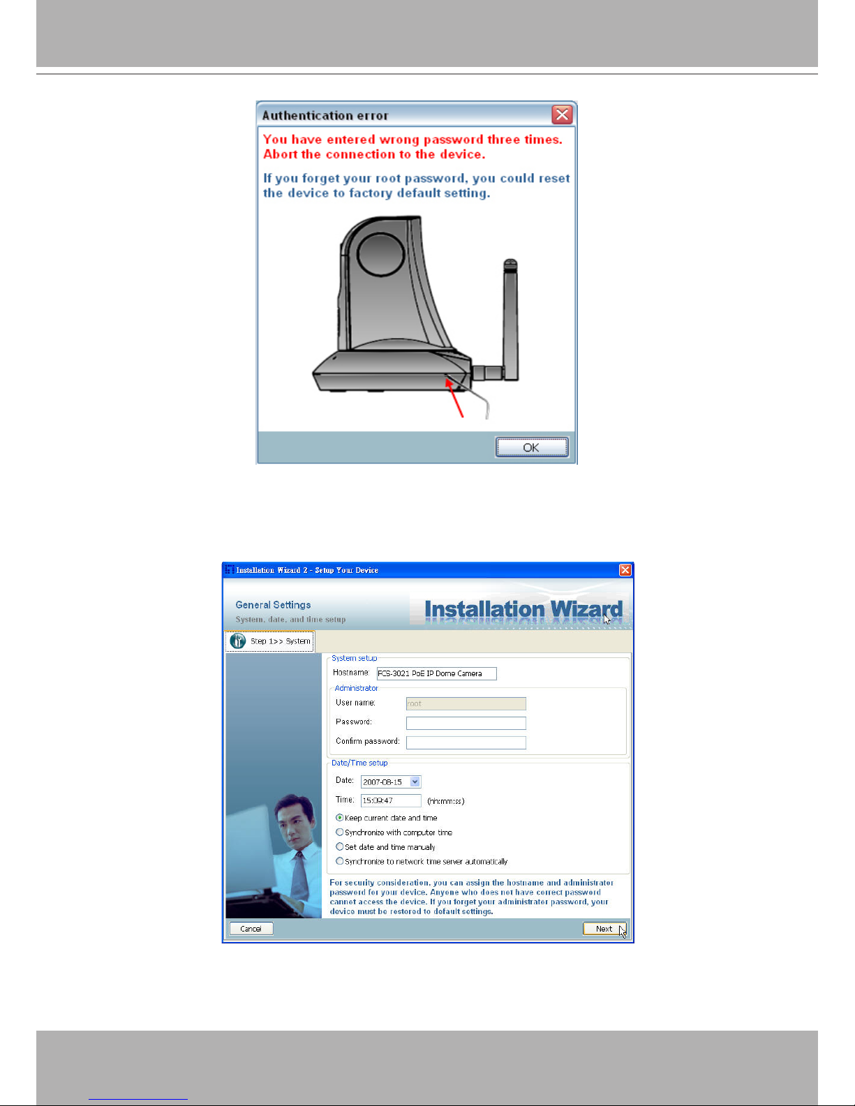
User's Manual - 13
Authentication error
System Setting
After connected to the selected device, the Installation Wizard will switch to system setting page
as below.
System setting page
14 - User's Manual
Click on this button to cancel the setup progress.
Click on this button to keep the present setting and go to the next page.
Change Host Name
The “Hostname” is used for the homepage title of main page and is displayed as the title in the
video window of the main page. The maximum string length is 40 characters or 20 characters
in double-byte-character-systems like Chinese or Japanese. But for some models supported
Unicode, the maximum string length depends on the characters you input, and it may less than
20 characters.
Change root password
To change the administrator’s password, type the new password in both “Password” and
“Confirm Password” text boxes identically. What is typed will be displayed as asterisks for
security purposes. The maximum password depends on the server you connected.
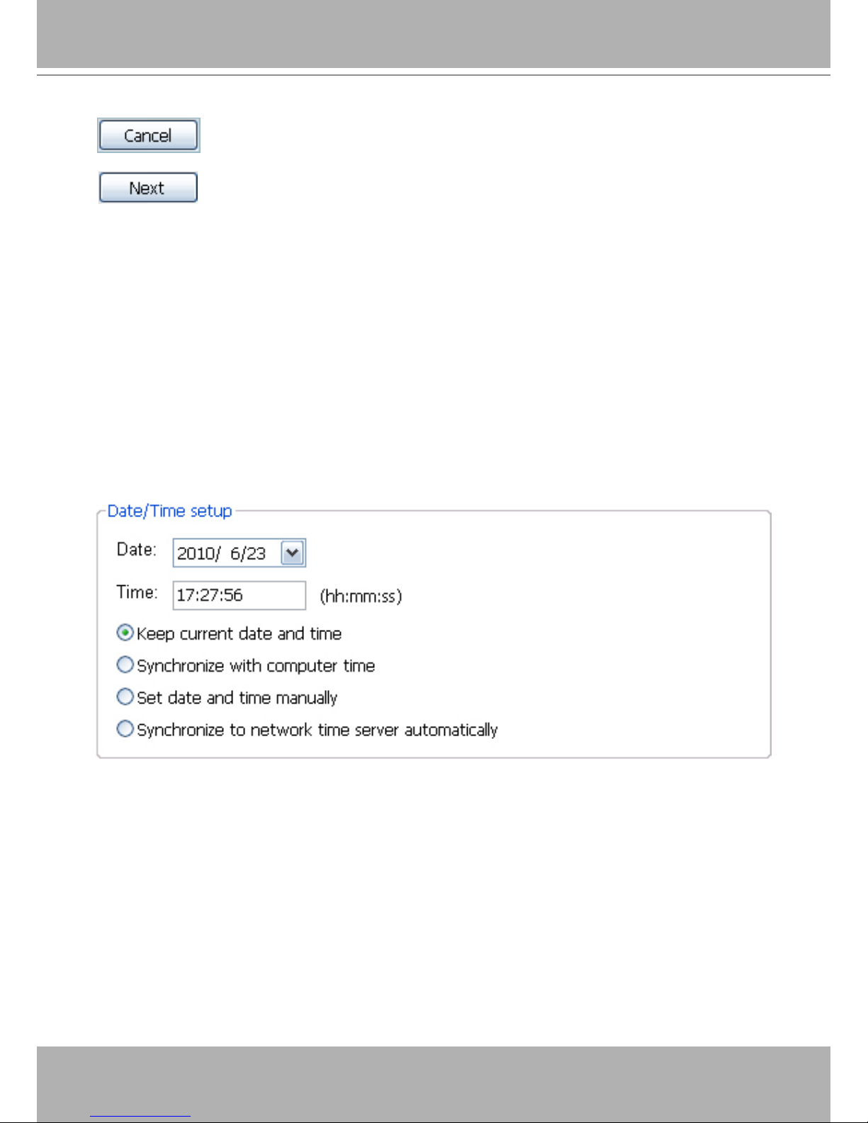
Adjust date and time
Date/Time setup
There are three ways to adjust system date and time:
1. “Synchronize with computer time”: The easiest way is to make device synchronized
with your computer time.
2. “Set date and time manually”: Set the date and time manually by entering new values.
Notice the format in the related eld while typing.
3. “Synchronize to network time server automatically”: Make device automatically
synchronize with timeservers over the Internet every hour.
If you want to keep the current date and time, please choose “Keep current date and time”.
User's Manual - 15
Network Setting
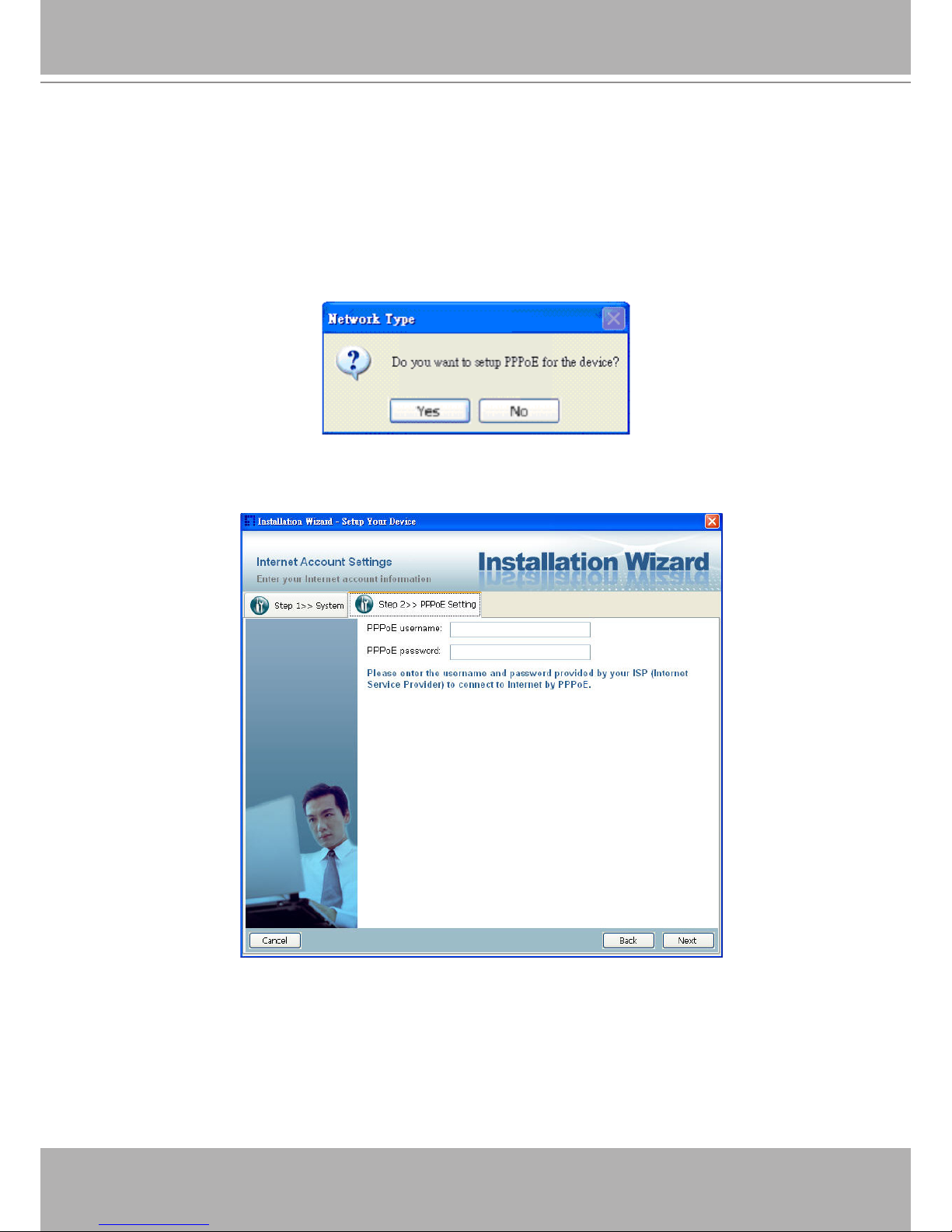
The Installation Wizard can help you to setup the network connection with LAN or PPPoE. After
you clicked on the “Next” button on the System page, the Installation Wizard would lead you to
the PPPoE setting page. If you want to connect your server to Internet via PPPoE, please click
on “Yes” to start the PPPoE setting process, or click on “No” to invoke the LAN setting.
Choosing the network type
PPPoE Setting
Network setting for PPPoE
If you click on “Yes” in the “Network Type” dialog window, you will be led to the PPPoE setting
page. In this page, you can input the “PPPoE username” and “PPPoE password” provided by
your ISP, and then the server will be set to PPPoE mode rather than LAN mode when the setup
is completed. If you don’t know the account information, please contact your ISP. After inputting
the account information, please click on the “Next” button to continue your next step.
16 - User's Manual
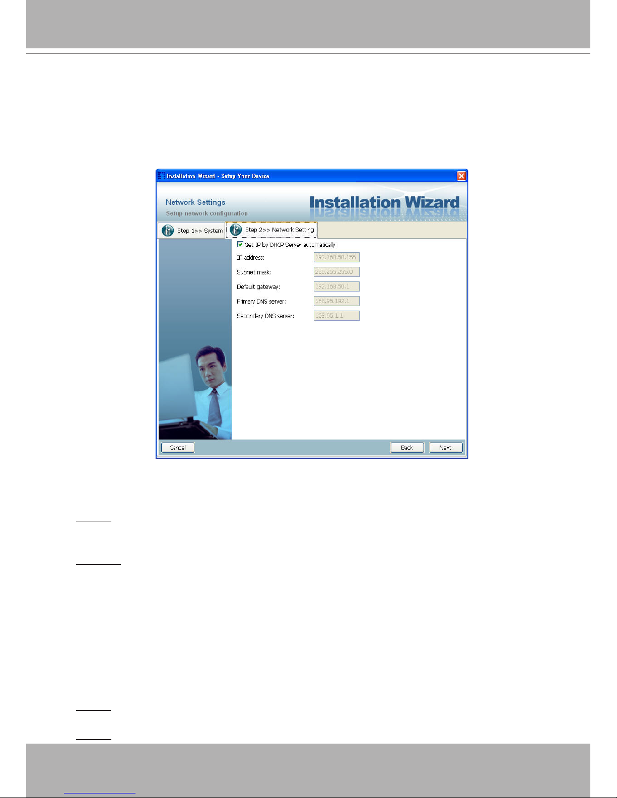
LAN Setting
If you click on “No” in the “Network Type” dialog window, you will be led to the Network setting
page. In this page, you can change the server’s IP address, subnet mask, default gateway,
primary DNS server, secondary DNS and DHCP server. Please refer to the below page.
Network Setting for LAN
You could set up the network with DHCP or xed IP:
1.DHCP: Check the “Get IP by DHCP Server automatically” will force the device to renew its
IP address whenever it reboots, and the related network conguration is provided by the DHCP
server.
2.Fixed IP: If you want the device to use a xed IP, please uncheck the “Get IP by DHCP Serv-
er automatically” checkbox and assign a valid IP address, subnet mask, default gateway and
DNS server for the device.
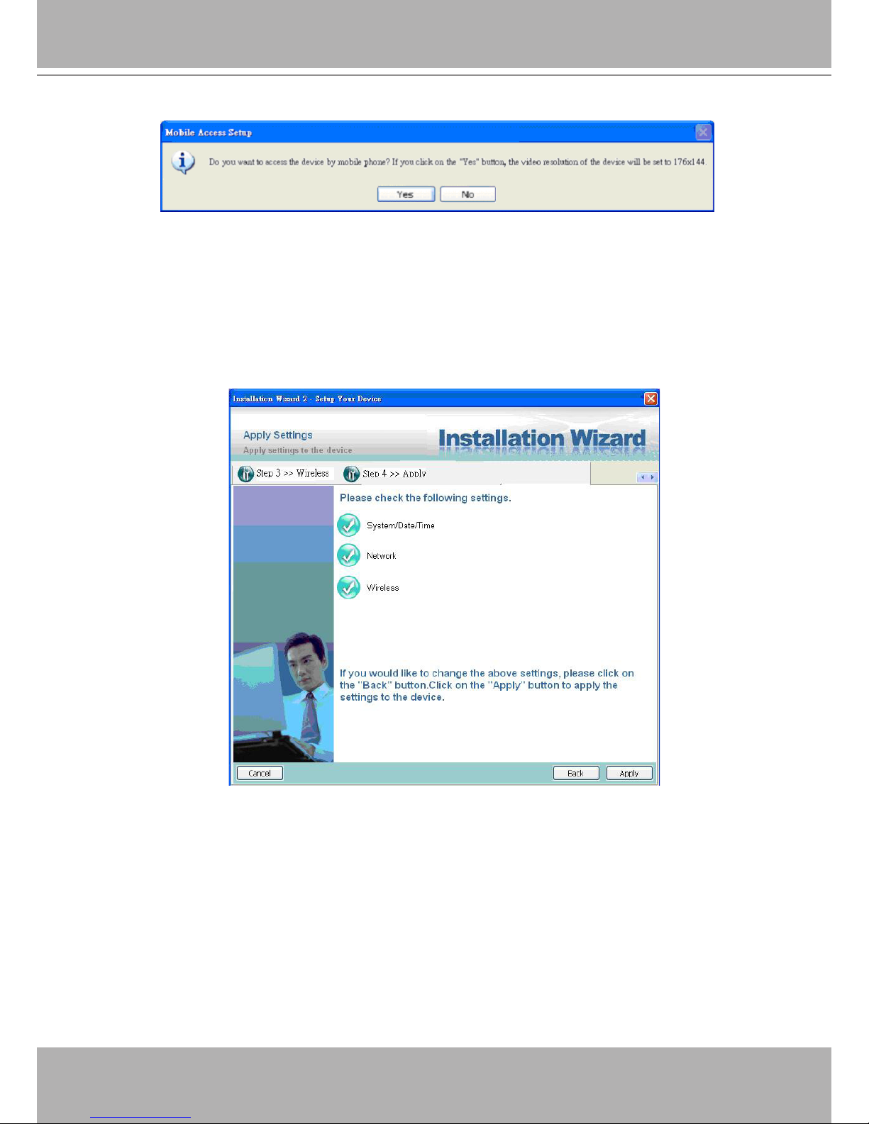
Mobile Access
After nished the DDNS setting and click on the Next button. If your device supports mobile
viewer and you want to access the device by mobile phone, you can enable the “Mobile Access”
by clicking on the Yes button. The Installation Wizard will do some setting for mobile viewing
toward the device:
1.Video: The video codec will be set to MPEG-4, and the resolution will be set to 176x144 pix-
els.
2.Audio: The audio codec will be set to AAC.
User's Manual - 17
Mobile Access
Apply to selected device
After conguring all the settings, the apply page will show up. Click on “Apply” button to apply
the changes to the selected device or click on “Back” button to go back to the previous page and
modify the setting again.
Apply page
When you click on the “Apply”, it will start to update your settings to server.
Upgrade
When you select one device or multiple devices (of the same model), the “Firmware Upgrade”
button will be enabled. Click on it to upgrade the rmware of the selected device(s). After click
on the “Firmware Upgrade” button, Installation Wizard will try to connect the selected device(s)
and lead you to the rmware upgrade page.

18 - User's Manual
Click on the “Firmware Upgrade”
Device Information
After connected to the selected device(s), it would display as below. If you select more than one
device, then the device information will show all the selected devices. You can switch to the
server info by click on the tab control.
Device information
User's Manual - 19
Multiple devices information
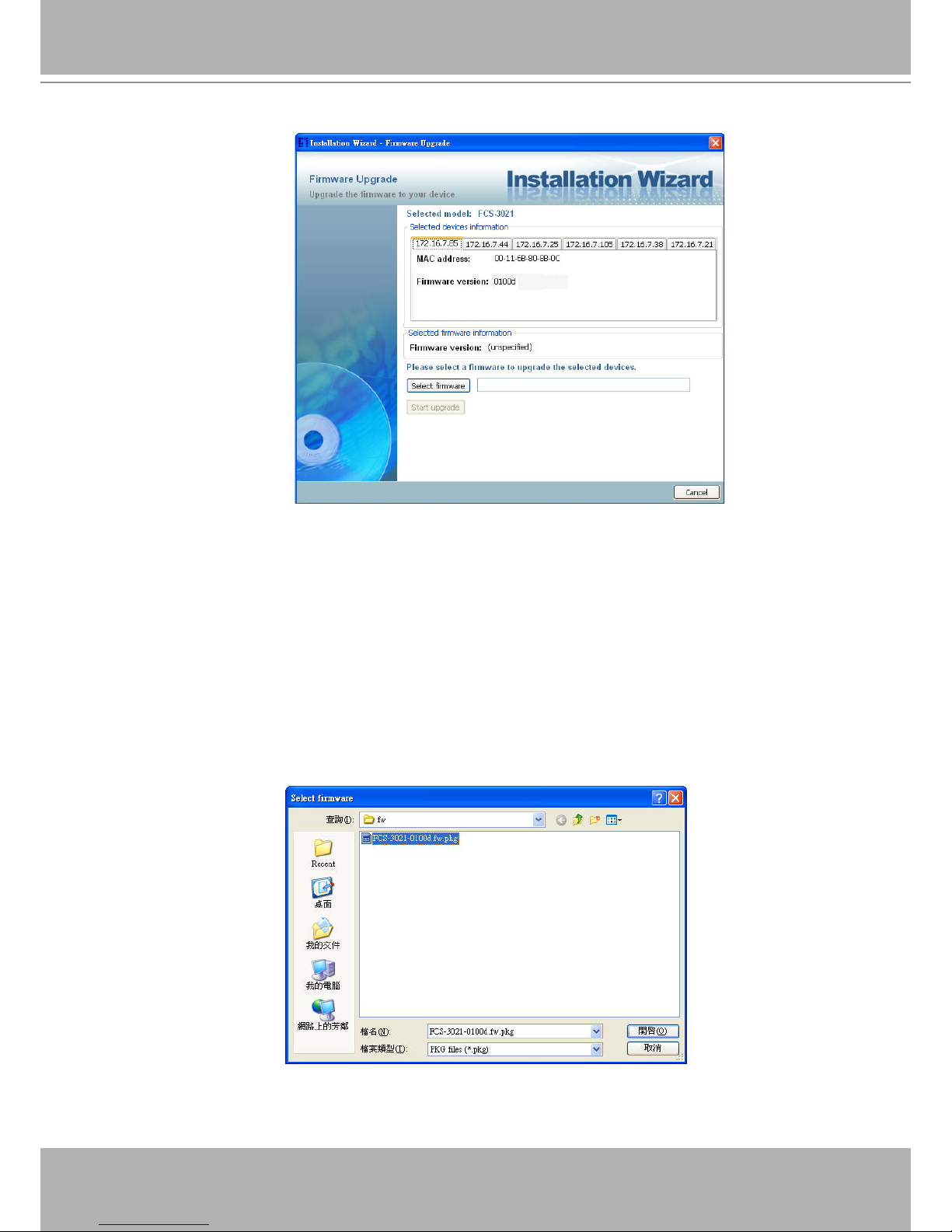
Firmware Information
The selected rmware information will show the information about the le that you selected.
Firmware version: The version number of the selected rmware.
Select Firmware
You can use the “Select rmware” button to browse the le that you want upgrade onto the selected device(s). After selected the le, Installation Wizard will check whether the le you select-
ed is correct. If it’s the correct version, then the package information will display the information
about the le and enable the “Start Upgrade” button. Therefore you can click on the button to
upgrade the rmware. If not, then it will be a pop-up warning message.
Select rmware
20 - User's Manual
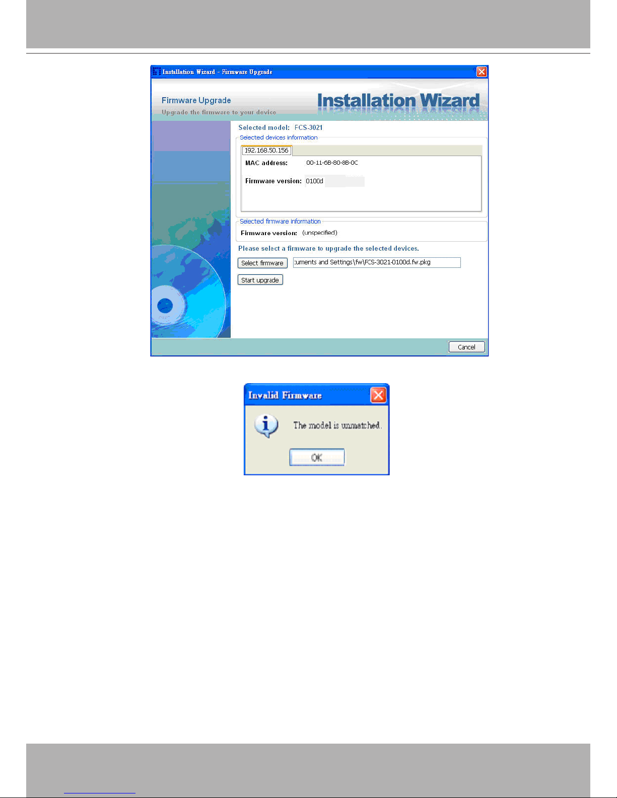
Firmware Information
Warning message for unmatched rmware
User's Manual - 21
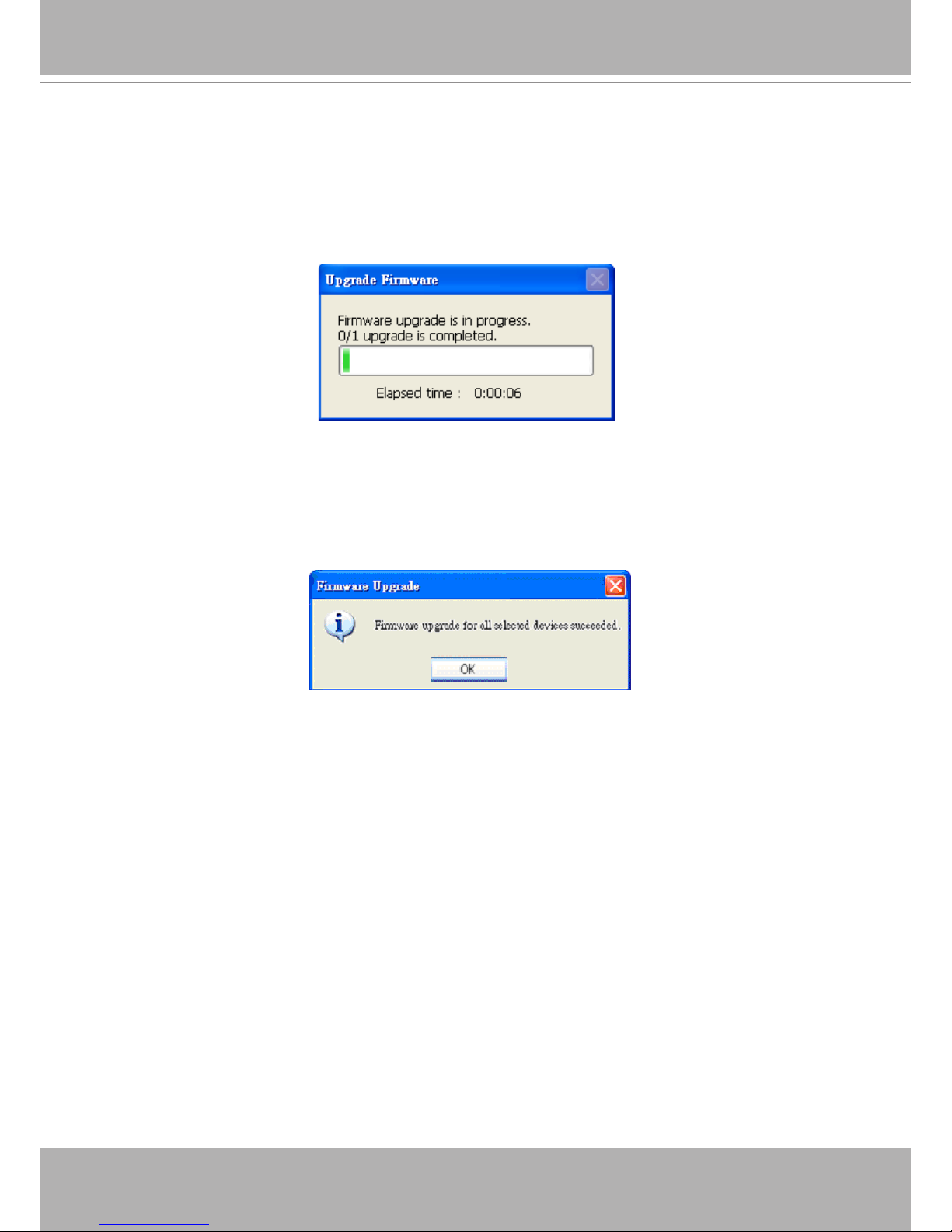
Start Upgrade
Clicking on the “Start Upgrade” button to upgrade the rmware of the selected device(s), and
it will be a pop-up dialog window to show the progress of the upgrading process. Usually, it will
take about 5 to 10 minutes to nish the rmware upgrading. It depends on your server model
and network bandwidth. We recommend you do the upgrade process in wired LAN environment
rather than PPPoE or wireless environment.
Update progress
After the upgrade process had been done, you could see the dialog window as below.
Please click on the button “OK” to nish it.
Upgrade Done
22 - User's Manual
Accessing the Network Camera
This chapter explains how to access the Network Camera through web browsers, RTSP players,
3GPP-compatible mobile devices, and LevelOne recording software.
Using Web Browsers
Use Installation Wizard 2 (IW2) to access to the Network Cameras on the LAN.
If your network environment is not a LAN, follow these steps to access the Netwotk Camera:
1. Launch your web browser (ex. Microsoft® Internet Explorer, Mozilla Firefox, or Netscape).
2. Enter the IP address of the Network Camera in the address eld. Press Enter.
3. The live video will be displayed in your web browser.
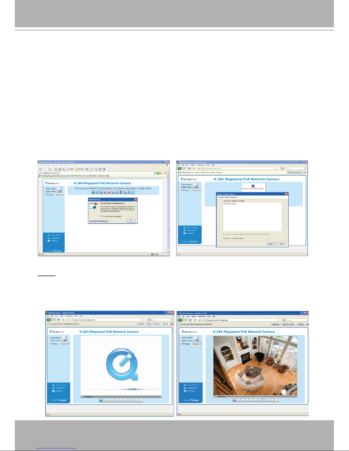
4. If it is the rst time installing the LevelOne network camera, an information bar will pop up as
shown below. Follow the instructions to install the required plug-in on your computer.
NOTE
► For Mozilla Firefox or Netscape users, your browser will use Quick Time to stream the live
video. If you donn’t have Quick Time on your computer, please download it rst, then launch
the web browser.
User's Manual - 23
► By default, the Network Camera is not password-protected. To prevent unauthorized access,
it is highly recommended to set a password for the Network Camera.
For more information about how to enable password protection, please refer to Security on
page 26.
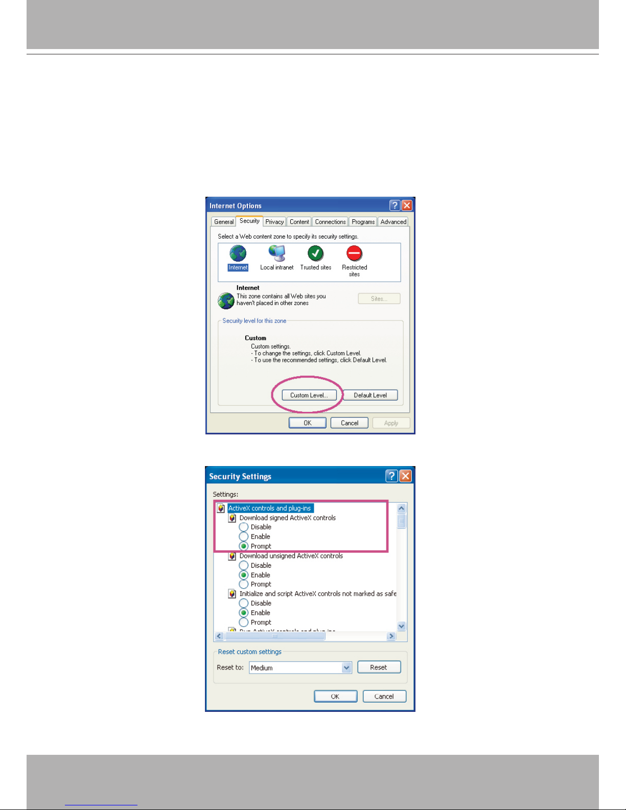
► If you see a dialog box indicating that your security settings prohibit running ActiveX®
Controls, please enable the ActiveX® Controls for your browser.
1. Choose Tools > Internet Options > Security > Custom Level.
2. Look for Download signed ActiveX® controls; select Enable or Prompt. Click OK.
3. Refresh your web browser, then install the Active X® control. Follow the instructions to
complete installation.
24 - User's Manual
Using RTSP Players
To view the MPEG-4 streaming media using RTSP players, you can use one of the following
players that support RTSP streaming.
Quick Time Player
Real Player
VLC media player
mpegable Player
pvPlayer
As most ISPs and players only allow RTSP streaming through port number 554, please set the
RTSP port to 554. For more information, please refer to RTSP Streaming on page 46.
For example:
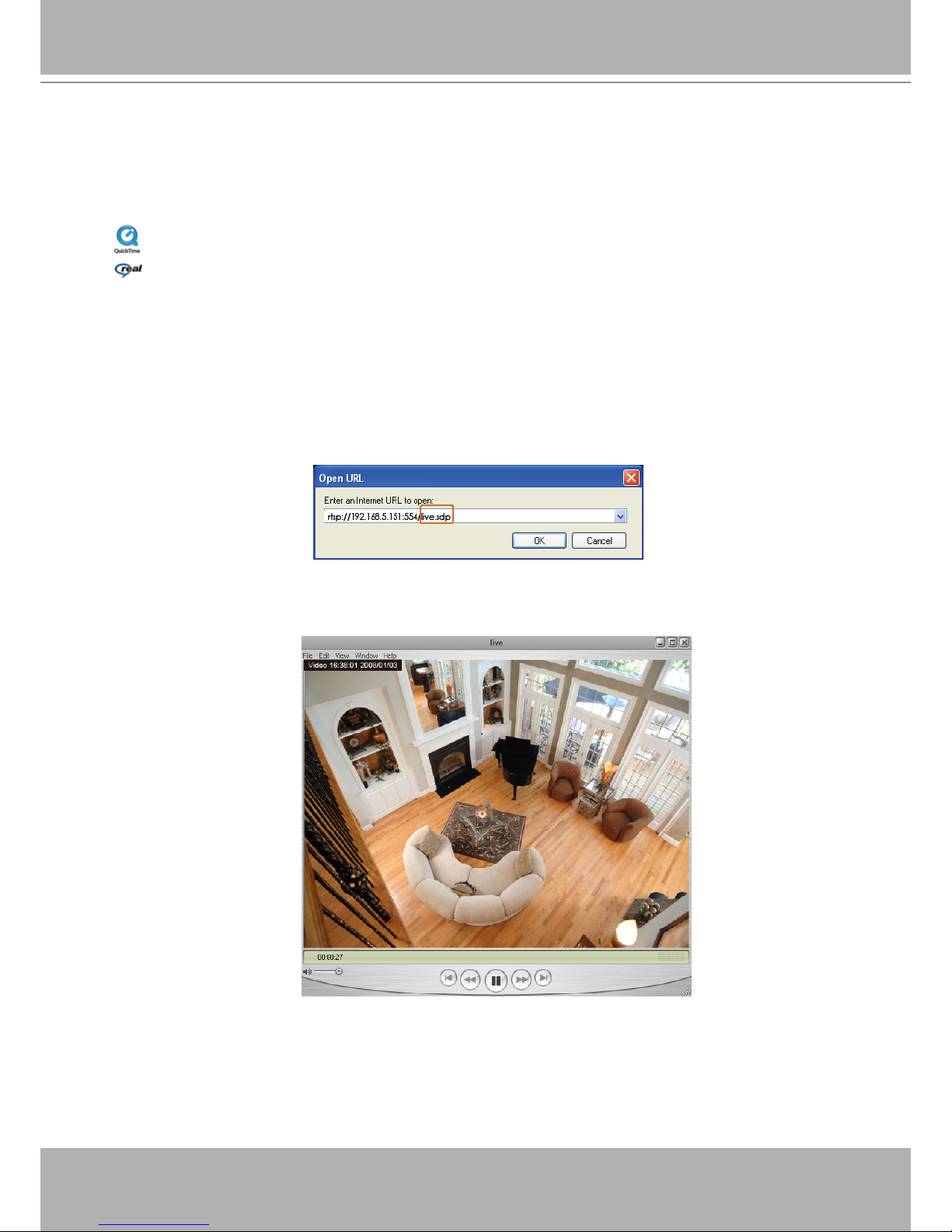
4. The live video will be displayed in your player.
For more information on how to configure the RTSP access name, please refer to RTSP
Streaming on page 46 for details.
1. Launch the RTSP player.
2. Choose File > Open URL. A URL dialog box will pop up.
3. The address format is rtsp://<ip address>:<rtsp port>/<RTSP streaming access name for
stream1 or stream2>
User's Manual - 25
Using 3GPP-compatible Mobile Devices
To view the streaming media through 3GPP-compatible mobile devices, make sure the Network
Camera can be accessed over the Internet. For more information on how to set up the Network
Camera over the Internet, please refer to Setup the Network Camera over the Internet on page 7.
To utilize this feature, please check the following settings on your Network Camera:
1. Because most players on 3GPP mobile phones do not support RTSP authentication, make
sure the authentication mode of RTSP streaming is set to disable.
For more information, please refer to RTSP Streaming on page 46.
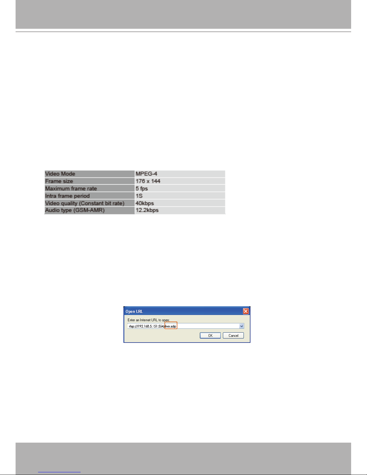
2. As the the bandwidth on 3G networks is limited, you will not be able to use a large video size.
Please set the video and audio streaming parameters as listed below.
For more information, please refer to Viewing Window on page 59.
3. As most ISPs and players only allow RTSP streaming through port number 554, please set
the RTSP port to 554. For more information, please refer to RTSP Streaming on page 46.
4. Launch the player on the 3GPP-compatible mobile devices (ex. Real Player).
5. Type the following URL commands into the player.
The address format is rtsp://<public ip address of your camera>:<rtsp port>/<RTSP streaming
access name for stream 3>.
For example:
26 - User's Manual
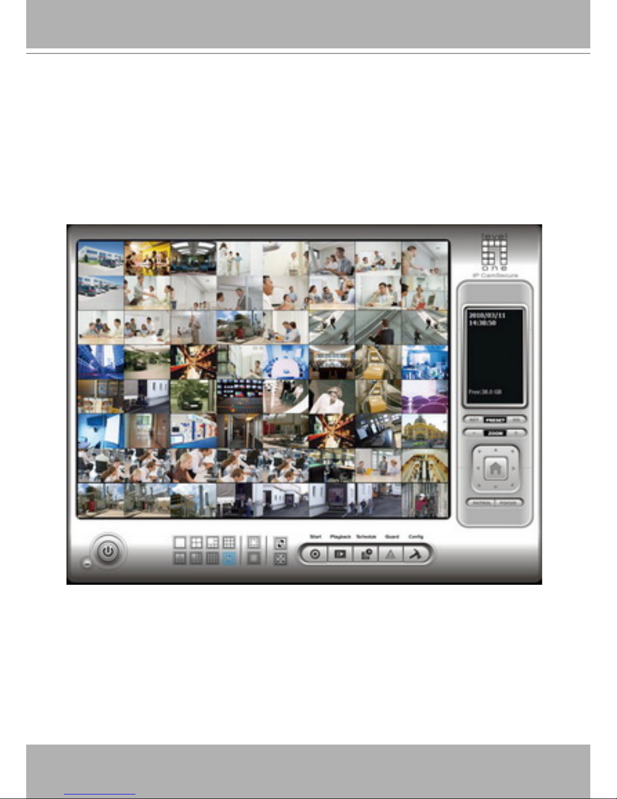
Using LevelOne Recording Software
The product software CD also contains recording software, allowing simultaneous monitoring
and video recording for multiple Network Cameras. Please install the recording software; then
launch the program to add the Network Camera to the Channel list. For detailed information
about how to use the recording software, please refer to the user’s manual of the software or
download it from http://www.LevelOne.com.
User's Manual - 27
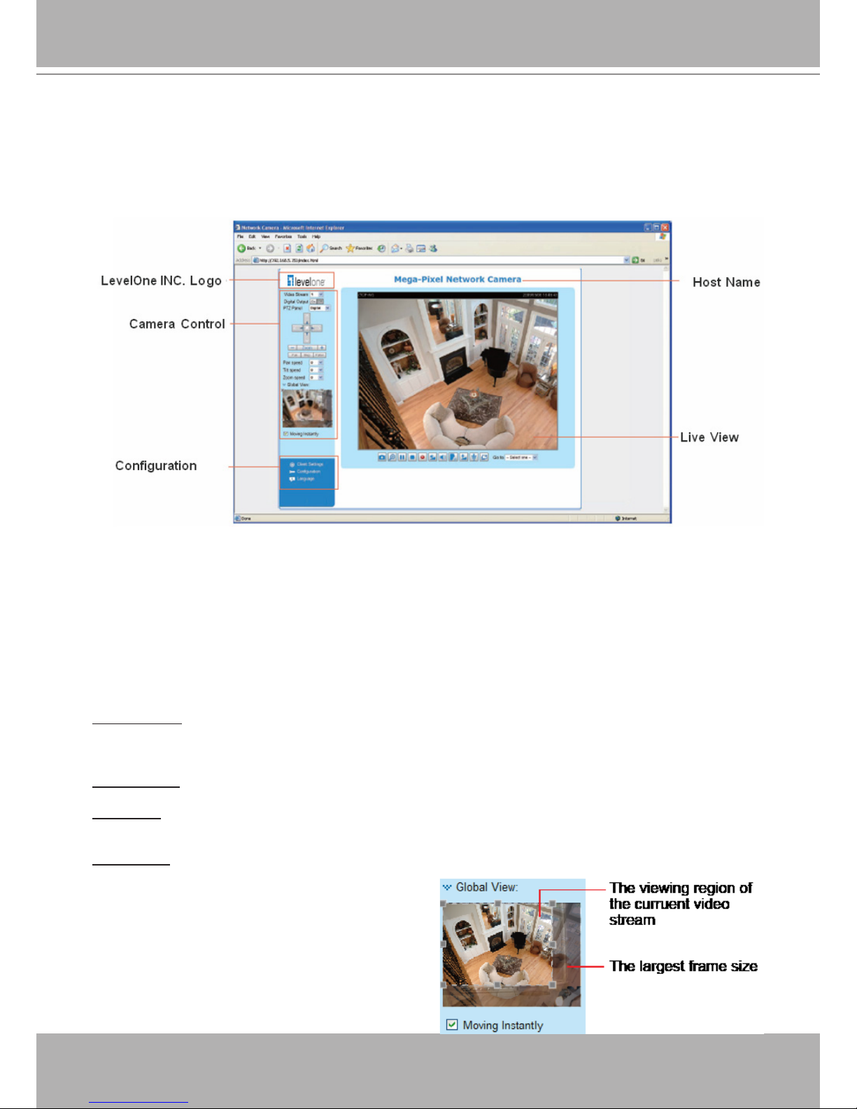
Main Page
This chapter explains the layout of the main page. It is composed of the following sections:
LevelOne INC. Logo, Host Name, Camera Control Area, Configuration Area, Menu, and Live
Video Window.
LevelOne INC. Logo
Click this logo to visit the LevelOne website.
Host Name
The host name can be customized to t your needs. For more information,
please refer to
System on page
24.
Camera Control Area
Video Stream: This Network Cmera supports multiple streams (stream 1 ~ 4) simultaneously. You can
select either one for live viewing. For more information about multiple streams, please refer to page 59
for detailed information.
Digital Output: Click to turn the digital output device on or off.
PTZ Panel: This Network Camera supports both “digital“ (e-PTZ) and “mechanical“ pan/tilt/zoom control.
Please refer to Camera Control on page 70 for detailed information.
Global View: Click on this item to display the Global
View window. The Global View window contains a full
view image (the largest frame size of the captured
video) and a oating frame (the viewing region of the
curruent video stream). The floating frame allows
users to control the e-PTZ function (Electron ic
Pan/Tilt/Zoom). For more information about e-PTZ
operation, please refer to E-PTZ Operation on page
75. For more information about how to set up the
viewing region of the current video stream, please
refer to Viewing Windows on page 59.
28 - User's Manual
Conguration Area
Client Settings: Click this button to access the client setting page. For more information, please refer to
Client Settings on page 21.
Conguration: Click this button to access the conguration page of the Network Camera. It is suggested
that a password be applied to the Network Camera so that only the administrator can configure the
Network Camera. For more information, please refer to Conguration on page 23.
Language: Click this button to choose a language for the user interface. Language options are available
in: English, Deutsch, Español, Français, Italiano,
日本語
, Português,
簡体中文
, and
繁體中文
.
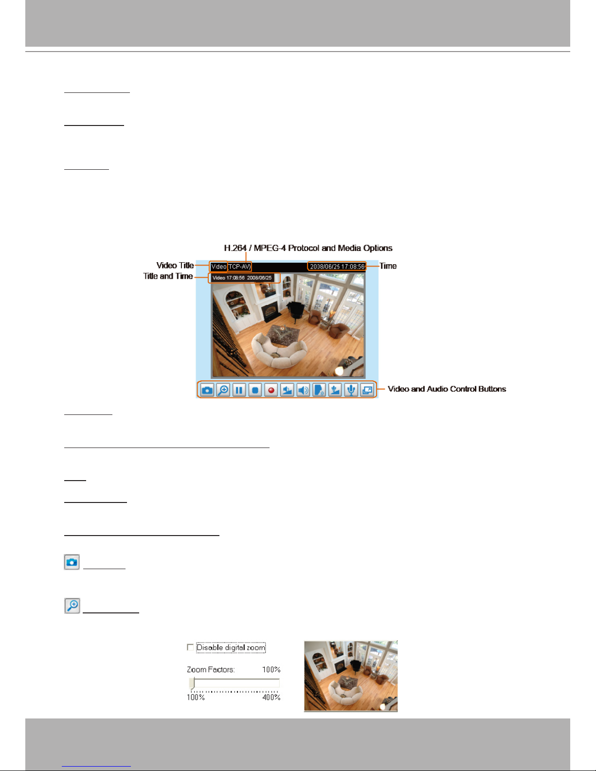
Live Video Window
■ The following window is displayed when the video mode is set to H.264 / MPEG-4:
Video Title: The video title can be congured. For more information, please refer to Video Settings on
page 53.
H.264 / MPEG-4 Protocol and Media Options: The transmission protocol and media options for H.264 /
MPEG-4 video streaming. For further conguration, please refer to Client Settings on page 21.
Time: Display the current time. For further conguration, please refer to Video Settings on page 53.
Title and Time: The video title and time can be stamped on the streaming video. For further conguration,
please refer to Video Settings on page 53.
Video and Audio Control Buttons: Depending on the Network Camera model and Network Camera
conguration, some buttons may not be available.
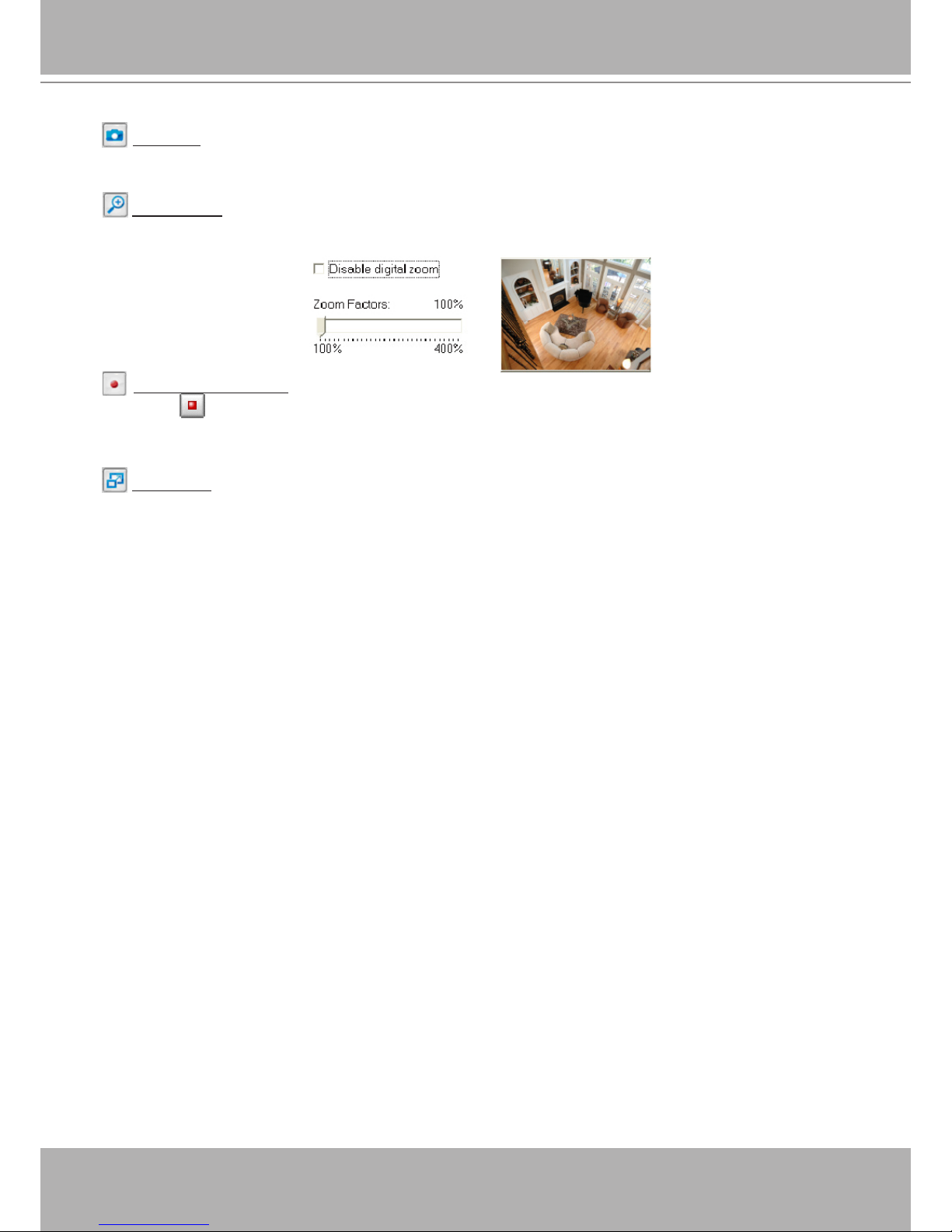
Snapshot: Click this button to capture and save still images. The captured images will be displayed
in a pop-up window. Right-click the image and choose Save Picture As to save it in JPEG (*.jpg) or BMP
(*.bmp) format.
Digital Zoom: Click and uncheck “Disable digital zoom” to enable the zoom operation. The navigation
screen indicates the part of the image being magnied. To control the zoom level, drag the slider bar. To
move to a different area you want to magnify, drag the navigation screen.
User's Manual - 29
Pause: Pause the transmission of the streaming media. The button becomes the Resume button
after clicking the Pause button.
Stop: Stop the transmission of the streaming media. Click the Resume button to continue
transmission.
Start MP4 Recording: Click this button to record video clips in MP4 file format to your computer.
Press the Stop MP4 Recording button to end recording. When you exit the web browser, video
recording stops accordingly. To specify the storage destination and le name, please refer to MP4 Saving
Options on page 22 for details.
Volume: When the Mute function is not activated, move the slider bar to adjust the volume on the
local computer.
Mute: Turn off the volume on the local computer. The button becomes the Audio On button after
clicking the Mute button.
Talk: Click this button to talk to people around the Network Camera. Audio will project from
the external speaker connected to the Network Camera. Click this button again to end talking
transmission.
Mic Volume: When the Mute function is not activated, move the slider bar to adjust the
microphone volume on the local computer.
Mute: Turn off the Mic volume on the local computer. The button becomes the Mic On button
after clicking the Mute button.
Full Screen: Click this button to switch to full screen mode. Press the “Esc” key to switch back to normal
mode.
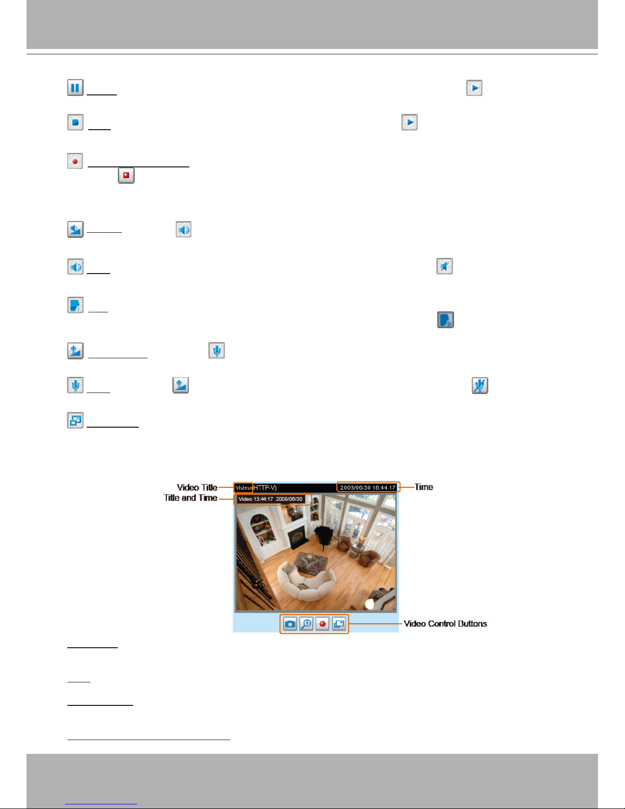
■ The following window is displayed when the video mode is set to MJPEG:
Video Title: The video title can be congured. For more information, please refer to Video Settings on
page 53.
Time: Display the current time. For more information, please refer to
Video Settings on page 53.
Title and Time: Video title and time can be stamped on the streaming video. For more information, please
refer to
Video Settings on page 53.
Video and Audio Control Buttons: Depending on the Network Camera model and Network Camera
conguration, some buttons may not be available.
30 - User's Manual
Snapshot: Click this button to capture and save still images. The captured images will be displayed
in a pop-up window. Right-click the image and choose Save Picture As to save it in JPEG (*.jpg) or BMP
(*.bmp) format.
Digital Zoom: Click and uncheck “Disable digital zoom” to enable the zoom operation. The navigation
screen indicates the part of the image being magnied. To control the zoom level, drag the slider bar. To
move to a different area you want to magnify, drag the navigation screen.
Start MP4 Recording: Click this button to record video clips in MP4 file format to your computer.
Press the Stop MP4 Recording button to end recording. When you exit the web browser, video
recording stops accordingly. To specify the storage destination and le name, please refer to MP4 Saving
Options on page 22 for details.
Full Screen: Click this button to switch to full screen mode. Press the “Esc” key to switch back to normal
mode.
 Loading...