

BCL 600i/BCL 601i
Bar code readers
EN 2016/10 - 50134518
We reserve the right to
make technical changes
Original operating instructions

1 About this document. . . . . . . . . . . . . . . . . . . . . . . . . . . . . . . . . . . . . . . . . . . . . . . 6
1.1 Used symbols and signal words . . . . . . . . . . . . . . . . . . . . . . . . . . . . . . . . . . . . . . . . . . . . . 6
2 Safety . . . . . . . . . . . . . . . . . . . . . . . . . . . . . . . . . . . . . . . . . . . . . . . . . . . . . . . . . . 7
2.1 Intended use . . . . . . . . . . . . . . . . . . . . . . . . . . . . . . . . . . . . . . . . . . . . . . . . . . . . . . . . . . . . 7
2.2 Foreseeable misuse . . . . . . . . . . . . . . . . . . . . . . . . . . . . . . . . . . . . . . . . . . . . . . . . . . . . . . 7
2.3 Competent persons . . . . . . . . . . . . . . . . . . . . . . . . . . . . . . . . . . . . . . . . . . . . . . . . . . . . . . . 7
2.4 Exemption of liability . . . . . . . . . . . . . . . . . . . . . . . . . . . . . . . . . . . . . . . . . . . . . . . . . . . . . . 8
2.5 Laser safety notices. . . . . . . . . . . . . . . . . . . . . . . . . . . . . . . . . . . . . . . . . . . . . . . . . . . . . . . 8
2.5.1 Laser safety notices– laser class 2 . . . . . . . . . . . . . . . . . . . . . . . . . . . . . . . . . . . . . . . . . . . 8
3 Device description . . . . . . . . . . . . . . . . . . . . . . . . . . . . . . . . . . . . . . . . . . . . . . . 11
3.1 Device overview. . . . . . . . . . . . . . . . . . . . . . . . . . . . . . . . . . . . . . . . . . . . . . . . . . . . . . . . . 11
3.2 Performance characteristics . . . . . . . . . . . . . . . . . . . . . . . . . . . . . . . . . . . . . . . . . . . . . . . 11
3.3 Device construction . . . . . . . . . . . . . . . . . . . . . . . . . . . . . . . . . . . . . . . . . . . . . . . . . . . . . . 13
3.4 Connection technology . . . . . . . . . . . . . . . . . . . . . . . . . . . . . . . . . . . . . . . . . . . . . . . . . . . 13
3.5 Display elements . . . . . . . . . . . . . . . . . . . . . . . . . . . . . . . . . . . . . . . . . . . . . . . . . . . . . . . . 14
3.5.1 Structure of the control panel. . . . . . . . . . . . . . . . . . . . . . . . . . . . . . . . . . . . . . . . . . . . . . . 14
3.5.2 Status display and operation . . . . . . . . . . . . . . . . . . . . . . . . . . . . . . . . . . . . . . . . . . . . . . . 15
3.5.3 LED indicators . . . . . . . . . . . . . . . . . . . . . . . . . . . . . . . . . . . . . . . . . . . . . . . . . . . . . . . . . . 15
3.6 Operational controls. . . . . . . . . . . . . . . . . . . . . . . . . . . . . . . . . . . . . . . . . . . . . . . . . . . . . . 16
3.7 External parameter memory . . . . . . . . . . . . . . . . . . . . . . . . . . . . . . . . . . . . . . . . . . . . . . . 16
4 Functions . . . . . . . . . . . . . . . . . . . . . . . . . . . . . . . . . . . . . . . . . . . . . . . . . . . . . . 17
4.1 autoReflAct . . . . . . . . . . . . . . . . . . . . . . . . . . . . . . . . . . . . . . . . . . . . . . . . . . . . . . . . . . . . 18
4.2 Reference codes . . . . . . . . . . . . . . . . . . . . . . . . . . . . . . . . . . . . . . . . . . . . . . . . . . . . . . . . 18
4.3 autoConfig . . . . . . . . . . . . . . . . . . . . . . . . . . . . . . . . . . . . . . . . . . . . . . . . . . . . . . . . . . . . . 18
4.4 Stand-alone connection . . . . . . . . . . . . . . . . . . . . . . . . . . . . . . . . . . . . . . . . . . . . . . . . . . . 19
4.5 Networking - Leuze multiNet plus . . . . . . . . . . . . . . . . . . . . . . . . . . . . . . . . . . . . . . . . . . . 19
4.6 Leuze multiScan . . . . . . . . . . . . . . . . . . . . . . . . . . . . . . . . . . . . . . . . . . . . . . . . . . . . . . . . 20
4.7 Heater . . . . . . . . . . . . . . . . . . . . . . . . . . . . . . . . . . . . . . . . . . . . . . . . . . . . . . . . . . . . . . . . 20
5 Reading techniques . . . . . . . . . . . . . . . . . . . . . . . . . . . . . . . . . . . . . . . . . . . . . . 21
5.1 Line scanner (single line). . . . . . . . . . . . . . . . . . . . . . . . . . . . . . . . . . . . . . . . . . . . . . . . . . 21
5.2 Line scanner with oscillating mirror . . . . . . . . . . . . . . . . . . . . . . . . . . . . . . . . . . . . . . . . . . 21
5.3 Omnidirectional reading. . . . . . . . . . . . . . . . . . . . . . . . . . . . . . . . . . . . . . . . . . . . . . . . . . . 22
6 Mounting. . . . . . . . . . . . . . . . . . . . . . . . . . . . . . . . . . . . . . . . . . . . . . . . . . . . . . . 24
6.1 Device arrangement . . . . . . . . . . . . . . . . . . . . . . . . . . . . . . . . . . . . . . . . . . . . . . . . . . . . . 24
6.1.1 Selecting a mounting location . . . . . . . . . . . . . . . . . . . . . . . . . . . . . . . . . . . . . . . . . . . . . . 24
6.1.2 Avoiding total reflection – Line scanner . . . . . . . . . . . . . . . . . . . . . . . . . . . . . . . . . . . . . . . 24
6.1.3 Avoiding total reflection – oscillating-mirror scanner . . . . . . . . . . . . . . . . . . . . . . . . . . . . . 25
6.1.4 Possible read angles between device and bar code . . . . . . . . . . . . . . . . . . . . . . . . . . . . . 25
6.2 Installing the external parameter memory . . . . . . . . . . . . . . . . . . . . . . . . . . . . . . . . . . . . . 26
7 Electrical connection . . . . . . . . . . . . . . . . . . . . . . . . . . . . . . . . . . . . . . . . . . . . . 28
7.1 Overview . . . . . . . . . . . . . . . . . . . . . . . . . . . . . . . . . . . . . . . . . . . . . . . . . . . . . . . . . . . . . . 28
7.2 PWR – Voltage supply and switching inputs/outputs 3 and 4 . . . . . . . . . . . . . . . . . . . . . . 29
7.3 SERVICE – USB interface (type A) . . . . . . . . . . . . . . . . . . . . . . . . . . . . . . . . . . . . . . . . . . 31
7.4 SW IN/OUT – Switching input/switching output . . . . . . . . . . . . . . . . . . . . . . . . . . . . . . . . . 31
7.5 HOST / BUS IN . . . . . . . . . . . . . . . . . . . . . . . . . . . . . . . . . . . . . . . . . . . . . . . . . . . . . . . . . 33
Leuze electronic BCL 600i/BCL 601i 3

7.6 BUS OUT. . . . . . . . . . . . . . . . . . . . . . . . . . . . . . . . . . . . . . . . . . . . . . . . . . . . . . . . . . . . . . 35
7.7 Cable lengths and shielding. . . . . . . . . . . . . . . . . . . . . . . . . . . . . . . . . . . . . . . . . . . . . . . . 36
7.8 Leuze multiNet plus . . . . . . . . . . . . . . . . . . . . . . . . . . . . . . . . . . . . . . . . . . . . . . . . . . . . . . 36
7.8.1 Wiring the multiNet plus. . . . . . . . . . . . . . . . . . . . . . . . . . . . . . . . . . . . . . . . . . . . . . . . . . . 37
7.8.2 The BCL 600i as network master . . . . . . . . . . . . . . . . . . . . . . . . . . . . . . . . . . . . . . . . . . . 38
7.8.3 The BCL 600i as network slave . . . . . . . . . . . . . . . . . . . . . . . . . . . . . . . . . . . . . . . . . . . . . 38
7.8.4 The BCL 601i as network slave . . . . . . . . . . . . . . . . . . . . . . . . . . . . . . . . . . . . . . . . . . . . . 39
8 Menu description . . . . . . . . . . . . . . . . . . . . . . . . . . . . . . . . . . . . . . . . . . . . . . . . 40
8.1 The main menus . . . . . . . . . . . . . . . . . . . . . . . . . . . . . . . . . . . . . . . . . . . . . . . . . . . . . . . . 40
8.2 Parameter menu . . . . . . . . . . . . . . . . . . . . . . . . . . . . . . . . . . . . . . . . . . . . . . . . . . . . . . . . 40
8.3 Language selection menu . . . . . . . . . . . . . . . . . . . . . . . . . . . . . . . . . . . . . . . . . . . . . . . . . 46
8.4 Service menu. . . . . . . . . . . . . . . . . . . . . . . . . . . . . . . . . . . . . . . . . . . . . . . . . . . . . . . . . . . 47
8.5 Actions menu . . . . . . . . . . . . . . . . . . . . . . . . . . . . . . . . . . . . . . . . . . . . . . . . . . . . . . . . . . . 47
8.6 Operation . . . . . . . . . . . . . . . . . . . . . . . . . . . . . . . . . . . . . . . . . . . . . . . . . . . . . . . . . . . . . . 48
9 Commissioning – Leuze electronic webConfig tool . . . . . . . . . . . . . . . . . . . . . . 49
9.1 Connecting the service USB interface . . . . . . . . . . . . . . . . . . . . . . . . . . . . . . . . . . . . . . . . 49
9.2 Installation . . . . . . . . . . . . . . . . . . . . . . . . . . . . . . . . . . . . . . . . . . . . . . . . . . . . . . . . . . . . . 49
9.2.1 System requirements. . . . . . . . . . . . . . . . . . . . . . . . . . . . . . . . . . . . . . . . . . . . . . . . . . . . . 49
9.2.2 Installing the USB driver . . . . . . . . . . . . . . . . . . . . . . . . . . . . . . . . . . . . . . . . . . . . . . . . . . 49
9.3 Starting the webConfig tool . . . . . . . . . . . . . . . . . . . . . . . . . . . . . . . . . . . . . . . . . . . . . . . . 50
9.4 Short description of the webConfig tool . . . . . . . . . . . . . . . . . . . . . . . . . . . . . . . . . . . . . . . 50
9.5 Module overview in the Configuration menu . . . . . . . . . . . . . . . . . . . . . . . . . . . . . . . . . . . 51
10 Starting up the device - Configuration . . . . . . . . . . . . . . . . . . . . . . . . . . . . . . . . 52
10.1 Measures to be performed prior to the initial commissioning . . . . . . . . . . . . . . . . . . . . . . 52
10.2 Starting the device . . . . . . . . . . . . . . . . . . . . . . . . . . . . . . . . . . . . . . . . . . . . . . . . . . . . . . . 52
10.3 BCL 600i operation . . . . . . . . . . . . . . . . . . . . . . . . . . . . . . . . . . . . . . . . . . . . . . . . . . . . . . 52
10.3.1Operation as stand-alone device . . . . . . . . . . . . . . . . . . . . . . . . . . . . . . . . . . . . . . . . . . . . 52
10.3.2Selecting the operating mode . . . . . . . . . . . . . . . . . . . . . . . . . . . . . . . . . . . . . . . . . . . . . . 52
10.3.3Operation as multiNet plus master . . . . . . . . . . . . . . . . . . . . . . . . . . . . . . . . . . . . . . . . . . 53
10.4 BCL 601i operation . . . . . . . . . . . . . . . . . . . . . . . . . . . . . . . . . . . . . . . . . . . . . . . . . . . . . . 54
10.5 Further settings . . . . . . . . . . . . . . . . . . . . . . . . . . . . . . . . . . . . . . . . . . . . . . . . . . . . . . . . . 55
10.5.1Decoding and processing the read data . . . . . . . . . . . . . . . . . . . . . . . . . . . . . . . . . . . . . . 55
10.5.2Control of the decoding . . . . . . . . . . . . . . . . . . . . . . . . . . . . . . . . . . . . . . . . . . . . . . . . . . . 56
10.5.3Control of the switching outputs. . . . . . . . . . . . . . . . . . . . . . . . . . . . . . . . . . . . . . . . . . . . . 56
10.6 Transmitting configuration data . . . . . . . . . . . . . . . . . . . . . . . . . . . . . . . . . . . . . . . . . . . . . 57
10.6.1Via the webConfig tool. . . . . . . . . . . . . . . . . . . . . . . . . . . . . . . . . . . . . . . . . . . . . . . . . . . . 57
10.6.2With the external parameter memory . . . . . . . . . . . . . . . . . . . . . . . . . . . . . . . . . . . . . . . . 57
11 Online commands . . . . . . . . . . . . . . . . . . . . . . . . . . . . . . . . . . . . . . . . . . . . . . . 58
11.1 General online commands. . . . . . . . . . . . . . . . . . . . . . . . . . . . . . . . . . . . . . . . . . . . . . . . . 58
11.2 Online commands for system control . . . . . . . . . . . . . . . . . . . . . . . . . . . . . . . . . . . . . . . . 63
11.3 Online commands for the parameter set operations . . . . . . . . . . . . . . . . . . . . . . . . . . . . . 64
12 Care, maintenance and disposal . . . . . . . . . . . . . . . . . . . . . . . . . . . . . . . . . . . . 71
12.1 Cleaning. . . . . . . . . . . . . . . . . . . . . . . . . . . . . . . . . . . . . . . . . . . . . . . . . . . . . . . . . . . . . . . 71
12.2 Servicing . . . . . . . . . . . . . . . . . . . . . . . . . . . . . . . . . . . . . . . . . . . . . . . . . . . . . . . . . . . . . . 71
12.3 Disposing . . . . . . . . . . . . . . . . . . . . . . . . . . . . . . . . . . . . . . . . . . . . . . . . . . . . . . . . . . . . . . 71
13 Diagnostics and troubleshooting . . . . . . . . . . . . . . . . . . . . . . . . . . . . . . . . . . . . 72
13.1 General causes of errors . . . . . . . . . . . . . . . . . . . . . . . . . . . . . . . . . . . . . . . . . . . . . . . . . . 72
Leuze electronic BCL 600i/BCL 601i 4

13.2 Interface errors . . . . . . . . . . . . . . . . . . . . . . . . . . . . . . . . . . . . . . . . . . . . . . . . . . . . . . . . . 72
14 Service and support . . . . . . . . . . . . . . . . . . . . . . . . . . . . . . . . . . . . . . . . . . . . . . 73
14.1 What to do should servicing be required? . . . . . . . . . . . . . . . . . . . . . . . . . . . . . . . . . . . . . 73
15 Technical data . . . . . . . . . . . . . . . . . . . . . . . . . . . . . . . . . . . . . . . . . . . . . . . . . . 74
15.1 General specifications . . . . . . . . . . . . . . . . . . . . . . . . . . . . . . . . . . . . . . . . . . . . . . . . . . . . 74
15.1.1 Line scanner . . . . . . . . . . . . . . . . . . . . . . . . . . . . . . . . . . . . . . . . . . . . . . . . . . . . . . . . . . . 74
15.1.2Oscillating-mirror scanner . . . . . . . . . . . . . . . . . . . . . . . . . . . . . . . . . . . . . . . . . . . . . . . . . 76
15.2 Heating models of the bar code readers . . . . . . . . . . . . . . . . . . . . . . . . . . . . . . . . . . . . . . 76
15.2.1Line scanner with heater . . . . . . . . . . . . . . . . . . . . . . . . . . . . . . . . . . . . . . . . . . . . . . . . . . 77
15.2.2Oscillating-mirror scanner with heating . . . . . . . . . . . . . . . . . . . . . . . . . . . . . . . . . . . . . . . 78
15.3 Dimensioned drawings . . . . . . . . . . . . . . . . . . . . . . . . . . . . . . . . . . . . . . . . . . . . . . . . . . . 79
15.4 Dimensioned drawings: Accessories . . . . . . . . . . . . . . . . . . . . . . . . . . . . . . . . . . . . . . . . . 81
15.5 Reading field curves / optical data. . . . . . . . . . . . . . . . . . . . . . . . . . . . . . . . . . . . . . . . . . . 82
15.6 Reading field curves . . . . . . . . . . . . . . . . . . . . . . . . . . . . . . . . . . . . . . . . . . . . . . . . . . . . . 82
15.6.1Medium Density (M) - optics . . . . . . . . . . . . . . . . . . . . . . . . . . . . . . . . . . . . . . . . . . . . . . . 84
15.6.2Low Density (F) - optics . . . . . . . . . . . . . . . . . . . . . . . . . . . . . . . . . . . . . . . . . . . . . . . . . . . 85
15.7 Reading field curves for heating devices . . . . . . . . . . . . . . . . . . . . . . . . . . . . . . . . . . . . . . 86
15.7.1Medium Density (M) - optics: (with heating) . . . . . . . . . . . . . . . . . . . . . . . . . . . . . . . . . . . 87
15.7.2Medium Density (M) - optics: (with heating) . . . . . . . . . . . . . . . . . . . . . . . . . . . . . . . . . . . 87
15.7.3Low Density (F) - optics: (with heating) . . . . . . . . . . . . . . . . . . . . . . . . . . . . . . . . . . . . . . . 89
15.7.4Low Density (F) - optics: (with heating) . . . . . . . . . . . . . . . . . . . . . . . . . . . . . . . . . . . . . . . 90
16 Ordering information and accessories . . . . . . . . . . . . . . . . . . . . . . . . . . . . . . . . 92
16.1 Nomenclature . . . . . . . . . . . . . . . . . . . . . . . . . . . . . . . . . . . . . . . . . . . . . . . . . . . . . . . . . . 92
16.2 Type overview . . . . . . . . . . . . . . . . . . . . . . . . . . . . . . . . . . . . . . . . . . . . . . . . . . . . . . . . . . 92
16.3 Accessories . . . . . . . . . . . . . . . . . . . . . . . . . . . . . . . . . . . . . . . . . . . . . . . . . . . . . . . . . . . . 93
17 EC Declaration of Conformity. . . . . . . . . . . . . . . . . . . . . . . . . . . . . . . . . . . . . . . 95
18 Appendix . . . . . . . . . . . . . . . . . . . . . . . . . . . . . . . . . . . . . . . . . . . . . . . . . . . . . . 96
18.1 ASCII character set . . . . . . . . . . . . . . . . . . . . . . . . . . . . . . . . . . . . . . . . . . . . . . . . . . . . . . 96
18.2 Bar code samples . . . . . . . . . . . . . . . . . . . . . . . . . . . . . . . . . . . . . . . . . . . . . . . . . . . . . . 100
18.2.1Module 0.3 . . . . . . . . . . . . . . . . . . . . . . . . . . . . . . . . . . . . . . . . . . . . . . . . . . . . . . . . . . . . 100
18.2.2Module 0.5 . . . . . . . . . . . . . . . . . . . . . . . . . . . . . . . . . . . . . . . . . . . . . . . . . . . . . . . . . . . . 101
Leuze electronic BCL 600i/BCL 601i 5
1 About this document
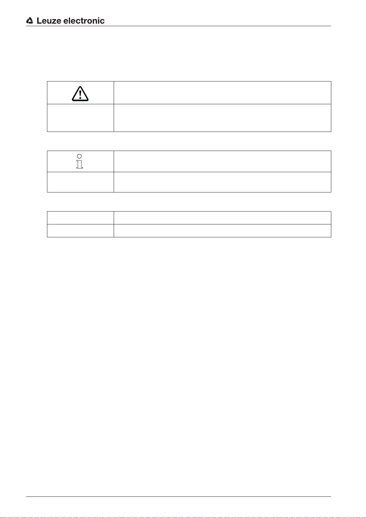
1.1 Used symbols and signal words
Table 1.1: Warning symbols and signal words
Symbol indicating dangers to persons
NOTE Signal word for property damage
Indicates dangers that may result in property damage if the measures for danger avoidance are not followed.
Table 1.2: Other symbols
Symbol for tips
Text passages with this symbol provide you with further information.
About this document
Table 1.3: Terms and abbreviations
BCL Bar code reader
CRT Code reconstruction technology
Symbol for action steps
Text passages with this symbol instruct you to perform actions.
Leuze electronic BCL 600i/BCL 601i 6
2 Safety
This sensor was developed, manufactured and tested in line with the applicable safety standards. It corresponds to the state of the art.
2.1 Intended use
The device is designed as a stationary high-speed scanner with integrated decoder for all common bar
codes for automatic object detection.
Areas of application
The device is specially designed for the following areas of application:
• Object identification on fast-moving conveyor lines
• Omnidirectional reading
CAUTION
Comply with conditions and regulations!
Observe the locally applicable legal regulations and the rules of the employer's liability insurance asso-
ciation.
Safety
2.2 Foreseeable misuse
Any use other than that defined under “Intended use” or which goes beyond that use is considered
improper use.
In particular, use of the device is not permitted in the following cases:
• in rooms with explosive atmospheres
• in circuits which are relevant to safety
• for medical purposes
CAUTION
Do not modify or otherwise interfere with the device!
Do not carry out modifications or otherwise interfere with the device.
The device must not be tampered with and must not be changed in any way.
The device must not be opened. There are no user-serviceable parts inside.
Repairs must only be performed by Leuze electronic GmbH + Co. KG.
2.3 Competent persons
Connection, mounting, commissioning and adjustment of the device must only be carried out by competent
persons.
Prerequisites for competent persons:
• They have a suitable technical education.
• They are familiar with the rules and regulations for occupational safety and safety at work.
• They are familiar with the technical description of the device.
• They have been instructed by the responsible person on the mounting and operation of the device.
Certified electricians
Electrical work must be carried out by a certified electrician.
Due to their technical training, knowledge and experience as well as their familiarity with relevant stan-
dards and regulations, certified electricians are able to perform work on electrical systems and independently detect possible dangers.
In Germany, certified electricians must fulfill the requirements of accident-prevention regulations BGV A3
(e.g. electrician foreman). In other countries, there are respective regulations that must be observed.
Leuze electronic BCL 600i/BCL 601i 7
2.4 Exemption of liability
Leuze electronic GmbH + Co. KG is not liable in the following cases:
• The device is not being used properly.
• Reasonably foreseeable misuse is not taken into account.
• Mounting and electrical connection are not properly performed.
• Changes (e.g., constructional) are made to the device.
2.5 Laser safety notices
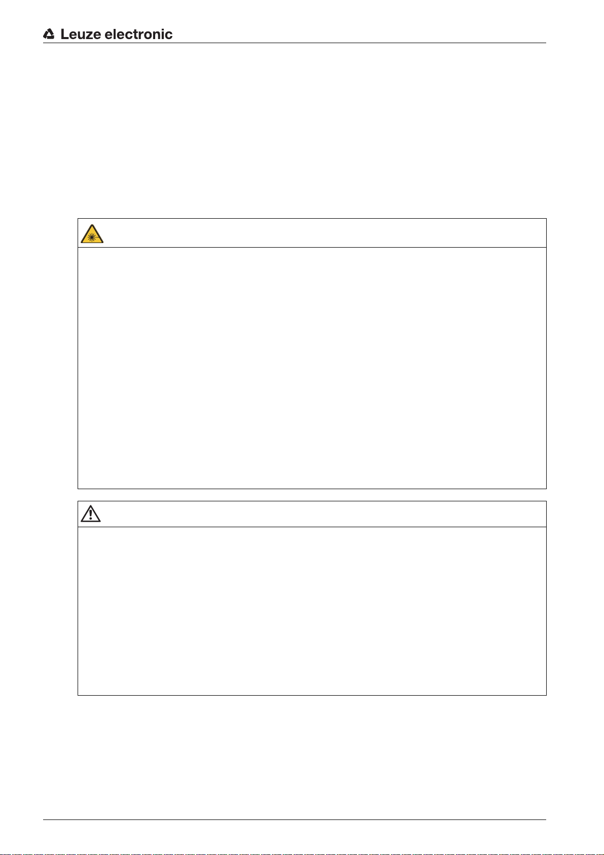
2.5.1 Laser safety notices– laser class 2
ATTENTION, LASER RADIATION – LASERCLASS2
Never look directly into the beam!
The device satisfies the requirements of IEC 60825-1:2007 (EN 60825-1:2007) safety regulations for a
product of laser class 2 as well as the U.S. 21 CFR 1040.10 regulations with deviations corresponding
to “Laser Notice No. 50” from June 24, 2007.
Never look directly into the laser beam or in the direction of reflected laser beams!
If you look into the beam path over a longer time period, there is a risk of injury to the retina.
Do not point the laser beam of the device at persons!
Interrupt the laser beam using a non-transparent, non-reflective object if the laser beam is accidentally
directed towards a person.
When mounting and aligning the device, avoid reflections of the laser beam off reflective surfaces!
CAUTION! The use of operating or adjusting devices other than those specified here or carrying out
of differing procedures may lead to dangerous exposure to radiation.
Observe the applicable statutory and local laser protection regulations.
The device must not be tampered with and must not be changed in any way.
There are no user-serviceable parts inside the device.
Repairs must only be performed by Leuze electronic GmbH + Co. KG.
Safety
CAUTION
Affix laser information and warning signs!
Laser information and warning signs attached to the device(see figure 2.1). Also included with the device
are self-adhesive laser warning and laser information signs (stick-on labels) in multiple languages (see
figure 2.3).
Affix the laser information sheet to the device in the language appropriate for the place of use.
When using the device in the U.S.A., use the stick-on label with the “Complies with 21 CFR 1040.10”
notice.
Affix the laser information and warning signs near the device if no signs are attached to the device (e.g.
because the device is too small) or if the attached laser information and warning signs are concealed
due to the installation position.
Affix the laser information and warning signs so that they are legible without exposing the reader to the
laser radiation of the device or other optical radiation.
Leuze electronic BCL 600i/BCL 601i 8
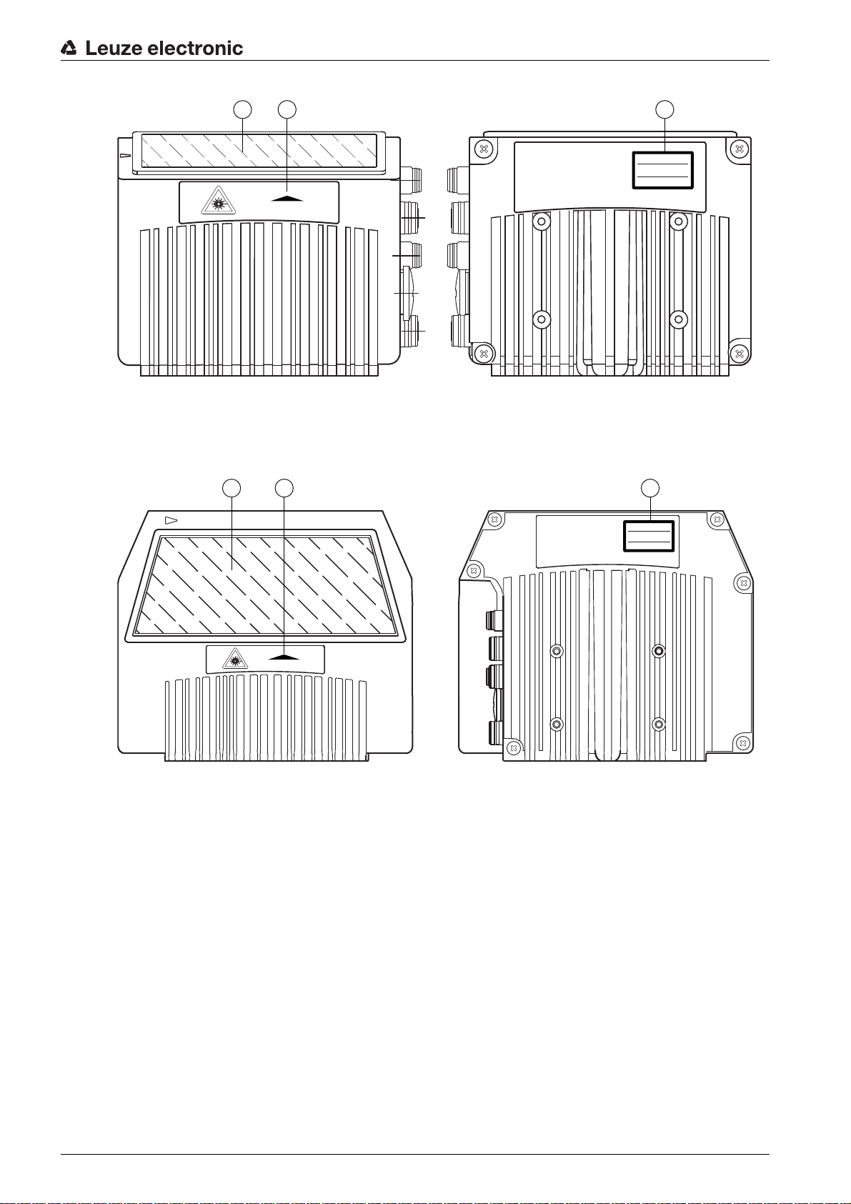
1 Laser aperture
LASER RADIATION
DO NOT STARE INTO BEAM
CLASS 2 LASER PRODUCT
EN 60825-1:2007
Maximum Output (peak):
Pulse duration:
Wavelength:
2 mW
<150 µs
405 nm
AVOID EXPOSURE – LASER RADIATION
IS EMITTED FROM THIS APERTURE
2 3
1
LASER RADIATION
DO NOT STARE INTO BEAM
CLASS 2 LASER PRODUCT
EN 60825-1:2007
Maximum Output (peak):
Pulse duration:
Wavelength:
2 mW
<150 μs
405 nm
AVOID EXPOSURE – LASER RADIATION
IS EMITTED FROM THIS APERTURE
2 3
1
2 Laser warning sign
3 Laser information sign with laser parameters
Figure 2.1: Laser aperture, laser warning and information signs - line scanner
Safety
1 Laser aperture
2 Laser warning sign
3 Laser information sign with laser parameters
Figure 2.2: Laser aperture, laser warning and information signs - oscillating-mirror scanner
Leuze electronic BCL 600i/BCL 601i 9

Safety
AVOID EXPOSURE – LASER RADIATION
IS EMITTED FROM THIS APERTURE
EXPOSITION DANGEREUSE – UN RAYONNEMENT
LASER EST ÉMIS PAR CETTE OUVERTURE
LASERSTRAHLUNG
NICHT IN DEN STRAHL BLICKEN
LASER KLASSE 2
DIN EN 60825-1:2008-05
Max. Leistung (peak):
Impulsdauer:
Wellenlänge:
RADIAZIONE LASER
NON FISSARE IL FASCIO
APARRECCHIO LASER DI CLASSE 2
EN 60825-1:2007
Potenza max. (peak):
Durata dell'impulso:
Lunghezza d'onda:
LASER RADIATION
DO NOT STARE INTO BEAM
CLASS 2 LASER PRODUCT
EN 60825-1:2007
Maximum Output (peak):
Pulse duration:
Wavelength:
RAYONNEMENT LASER
NE PAS REGARDER DANS LE FAISCEAU
APPAREIL À LASER DE CLASSE 2
EN 60825-1:2007
Puissance max. (crête):
Durée d`impulsion:
Longueur d`onde:
RADIACIÓN LÁSER
NO MIRAR FIJAMENTE AL HAZ
PRODUCTO LÁSER DE CLASE 2
EN 60825-1:2007
Potencia máx. (peak):
Duración del impulso:
Longitud de onda:
RADIAÇÃO LASER
NÃO OLHAR FIXAMENTE O FEIXE
EQUIPAMENTO LASER CLASSE 2
EN 60825-1:2007
Potência máx. (peak):
Período de pulso:
Comprimento de onda:
LASER RADIATION
DO NOT STARE INTO BEAM
CLASS 2 LASER PRODUCT
IEC 60825-1:2007
Complies with 21 CFR 1040.10
Maximum Output (peak):
Pulse duration:
Wavelength:
䉏⏘戟⺓
▎䦃展⏘㧮
伊䉏⏘ℶ❐
GB7247.1-2012
㦏⮶戢⒉᧤⽿⋋᧥
厘⑁㖐兼㢅梃
㽱栎
2 mW
<150 µs
405 nm
2 mW
<150 µs
405 nm
2 mW
<150 µs
405 nm
2 mW
<150
µ
s
405 nm
2 mW
<150 µs
405 nm
2 mW
<150 µs
405 nm
2 mW
<150 µs
405 nm
2 mW
<150 µs
405 nm
50127630
Figure 2.3: Laser warning and information signs – supplied stick-on labels
Leuze electronic BCL 600i/BCL 601i 10
3 Device description
2
1
3.1 Device overview
Bar code readers of the BCL 600i series are high-speed scanners with integrated decoder for all
commonly used bar codes, e.g. 2/5 Interleaved, Code 39, Code 128, EAN 8/13 etc., as well as codes from
the GS1 DataBar family.
Bar code readers of the BCL 600i series are available in various optics models as well as line scanners
and oscillating mirrors and also optionally as heated models.
Device description
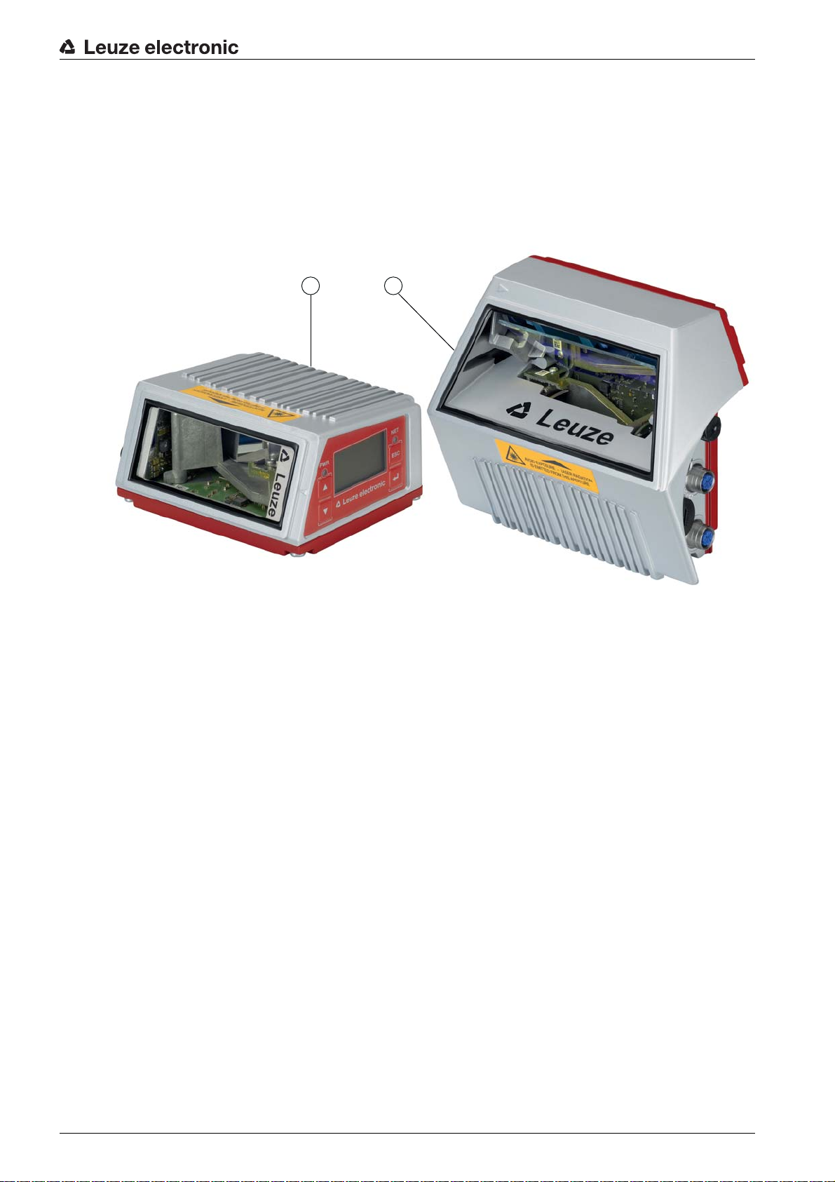
1 Line scanner
2 Oscillating-mirror scanner
Figure 3.1: Line scanner and oscillating-mirror scanner
The extensive options for device configuration via display or software enable adaptation to a multitude of
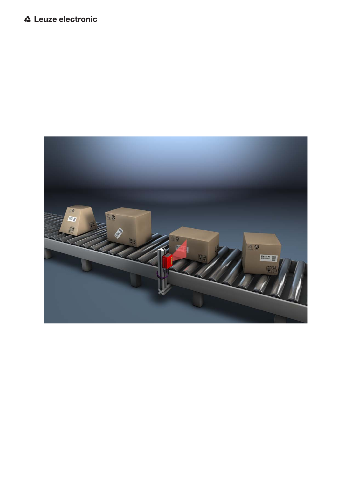
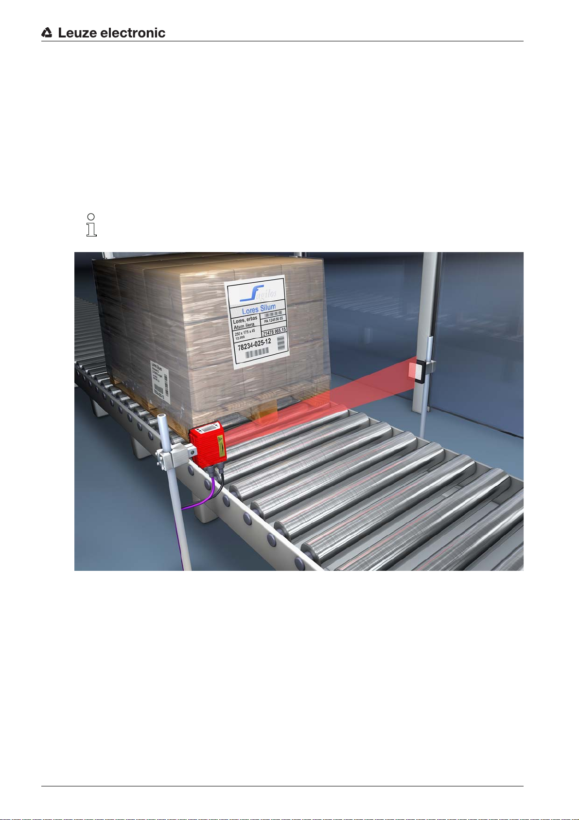
reading tasks. Due to the large reading distance combined with the great depth of field and a very compact
construction, the device is ideally suited for package and pallet transportation systems. In general, the bar
code readers of the BCL 600i series are designed for the conveyor and storage technology market.
The interfaces (RS 232, RS 485 and RS 422) integrated in the various device models and the fieldbus
systems (Profibus DP, PROFINET-IO, Ether net TCP/IP / UDP and Ethernet/IP) of the BCL 600i series bar
code readers offer optimum connection to the superior host system.
3.2 Performance characteristics
• Integrated fieldbus connectivity = i -> Plug-and-Play fieldbus coupling and easy networking
• Numerous interface variants facilitate connection to the superior systems
• RS 232, RS 422 as well as with integrated multiNet plus master
• RS 485 and multiNet plus slave
• Alternatively, various fieldbus systems, such as
PROFIBUS DP
PROFINET-IO
Ethernet TCP/IP and UDP
Ethernet/IP
Leuze electronic BCL 600i/BCL 601i 11

Device description
• Integrated code reconstruction technology (CRT) enables the identification of soiled or damaged bar
codes
• Maximum depth of field and reading distances from 400 mm to 1450 mm
• Large optical opening angle and, thus, large reading field width
• High scanning rate of 800 / 1000 scans/s for fast reading tasks
• Intuitive, backlit, multi-language display with user-friendly menu navigation
• Integrated USB 1.1 service interface
• Adjustment of all device parameters with a web browser
• Connection options for an external parameter memory
• Easy alignment- and diagnostics functions
• M 12 connections with Ultra-Lock ™ technology
• Four freely programmable switching inputs/outputs for the activation or signaling of states
• Automatic monitoring of the read quality with autoControl
• Automatic recognition and setting of the bar code type using autoConfig
• Reference code comparison
• Optional heating models to -35 °C
• Heavy-duty housing of degree of protection IP 65
Leuze electronic BCL 600i/BCL 601i 12
3.3 Device construction
1
1
2
3
5
6
4
66
Device description
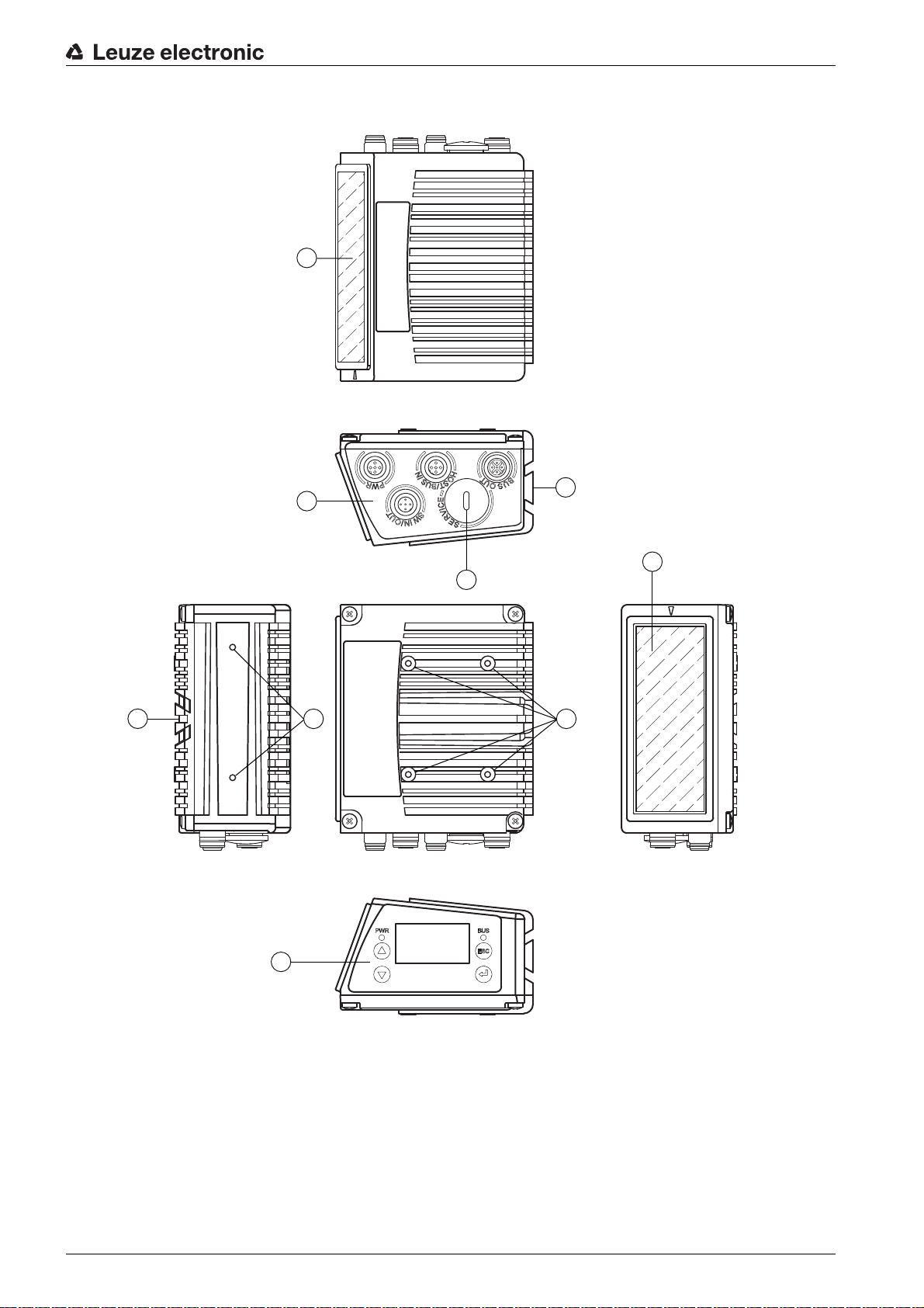
1 Reading window
2 Control panel with display, LEDs and buttons
3 M 12 connection technology
4 USB interface
5 Dovetail mounting
6 M4 mounting thread
Figure 3.2: Device construction
3.4 Connection technology
The bar code readers are connected using variously coded M 12 connectors. This ensures unique connection assignments.
Leuze electronic BCL 600i/BCL 601i 13
Device description
3 4 5
2
1
3
2
1
4
5
6
The additional USB interface is used for configuring the device.
The two product series BCL 600i and BCL 601i differ in their interfaces and in their function as multiNet
plus master or slave.
Table 3.1: BCL 600i/BCL 601i interfaces
HOST / BUS IN BUS OUT
BCL 600i
(Stand alone or multiNet plus Master)
BCL 601i
(multiNet plus slave)
RS 232 / RS 422 RS 485
RS 485 RS 485
For the locations of the individual device connections, please refer to the device detail shown below.
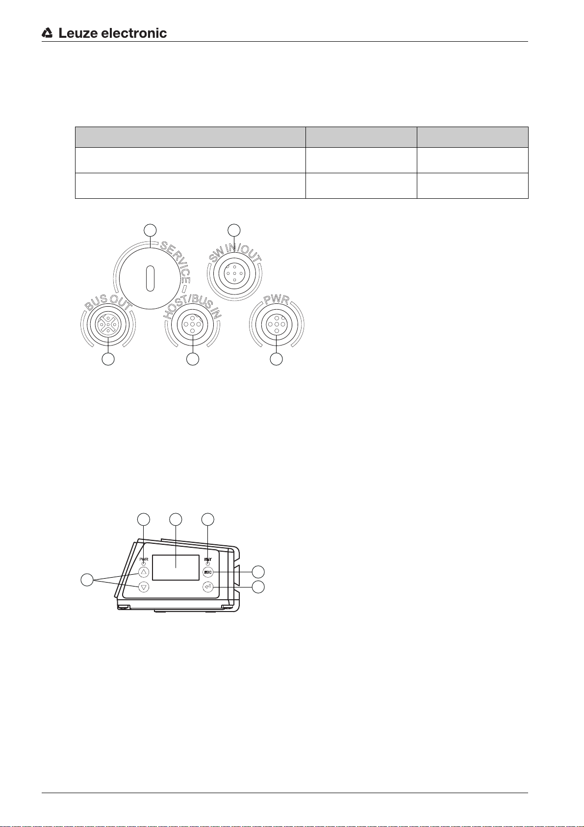
1 Service, USB socket, type A
2 SW IN/OUT, M 12 socket (A-coded)
3 Bus OUT, M 12 socket (D-coded)
4 HOST/BUS IN, M 12 socket (D-coded)
5 PWR, M 12 connector (A-coded)
Figure 3.3: Location of the electrical connections
3.5 Display elements
3.5.1 Structure of the control panel
1PWR LED
2 NET LED
3 Navigation buttons
4 Escape button
5 Enter button
6 Display
Figure 3.4: Structure of the control panel
Leuze electronic BCL 600i/BCL 601i 14
3.5.2 Status display and operation
Indicators in the display
le 3.2: Status displays of the switching inputs/outputs
Tab
Device description
IO1
Switching input or switching output 1 active (function dependent on set configuration).
Default: Switching input with the “Reading gate activation”
IO2 Switching input or switching output 2 active (function dependent on set configuration).
Default: Input with the “Teach-in”
IO3 Switching input or switching output 3 active (function dependent on set configuration).
Default: Switching input with the “Reading gate activation”
IO4 Switching input or switching output 4 active (function dependent on set configuration).
Default: Switching output with the “No read”
ATT Warning (Attention)
ERR Internal device error (Error) -> The device must be sent in for inspection
Table 3.3: Status display of the USB interface
USB The device is connected to a PC via the USB interface.
MS An external parameter memory is properly connected to the USB interface of the device.
Read result
The read bar code information is displayed.
3.5.3 LED indicators
PWR LED
Off Device OFF
Flashes green Device ok, initialization phase
Green,
continuous light
Orange,
continuous light
Flashes red Device ok, warning set
• No supply voltage
• No bar code reading possible
• Voltage connected
• Self test running
• Initialization running
Device ok
• Bar code reading possible
• Self test successfully finished
• Device monitoring active
Service mode
• Bar code reading possible
• Configuration via the USB service interface
• Configuration via the display
• No data on the host interface
• Bar code reading possible
• Temporary operating fault
Red,
continuous light
Leuze electronic BCL 600i/BCL 601i 15
Device error / parameter enable
• No bar code reading possible
NET LED
Off No supply voltage
• No communication possible
Flashes green Initialization
• Of the device, establishing communication
Device description
Green,
Operation ok
continuous light
Flashes red Communication error
Red,
continuous light
Network error
No communication (protocol) to IO controller established (no data exchange)
3.6 Operational controls
Navigating within the menus
Use the navigation buttons to move through the menu. Activate the desired selection with the enter
button .
Press the escape button to move up one menu level.
When one of the buttons is actuated, the display illumination is activated for 10 min.
Setting values
Set the desired value with the navigation buttons and the enter button .
An accidental incorrect entry can be corrected by selecting the left arrow button and then pressing the
enter button.
Then use the navigation buttons to select save and save the set value by pressing the enter button.
• Network mode ok
• Parameterization or configuration failed (parameter failure)
•IO error
• No data exchange
ESC
Selecting options
Set the desired option with the navigation buttons and the enter button .
3.7 External parameter memory
The optionally available external parameter memory – based on a USB memory stick (compatible with
version 1.1) – is housed in an external hood with integrated connectors which cover the USB service interface when installed (IP 65).
The external parameter memory makes it easy and reduces the time needed to replace a device on site
by providing a copy of the current parameter set of the device. This eliminates the need to configure the
exchanged device manually.
The delivery contents of the external parameter memory include the hood with integrated connectors with
unscrewable cover and the USB memory stick.
For transferring the configuration with the aid of the external parameter memory see chapter 6.2.
Leuze electronic BCL 600i/BCL 601i 16
4 Functions
General information
The integrated fieldbus connectivity = i contained in the bar code readers of the BCL 600i series facilitates
the use of identification systems which function without connection unit or gateways. The integrated
fieldbus interface considerably simplifies handling. The Plug-and-Play concept enables easy networking
and very simple commissioning: Directly connect the respective fieldbus and all configuration is performed
with no additional software.
For decoding bar codes, the bar code readers of the BCL 600i series make available the proven CRT
decoder with code reconstruction technology:
The proven code reconstruction technology (CRT) enables bar code readers of the BCL 600i series to read
bar codes with a small bar height, as well as bar codes with a damaged or soiled print image.
With the aid of the CRT decoder, bar codes can also be read without problem in other demanding situations, such as with a large tilt angle (azimuth angle or even twist angle).
Functions
Figure 4.1: Possible bar code orientation
The BCL 600i / BCL 601i can be operated and configured using the integrated webConfig tool via the USB
service interface; alternatively, the bar code readers can be adjusted using configuration commands via
the host/service interface.
The device needs a suitable activation to start a read process as soon as an object is in the reading field.
This opens a time window (reading gate) in the device for the read process during which the bar code
reader has time to detect and decode a bar code.
In the basic setting, triggering takes place through an external reading cycle signal. Alternative activation
options include online commands via the host interface and the autoReflAct function. Through the read
operation, the device collects additional useful pieces of data for diagnosis which can also be transmitted
to the host. The quality of the read operation can be inspected using the alignment mode which is integrated in the webConfig tool.
A multi-language display with buttons is used to operate the device as well as for visualization purposes.
Two LEDs provide additional optical information on the current operating state of the device.
The four freely configurable switching inputs/outputs SWIO 1 … SWIO 4 can be assigned various functions and control e.g. activation of the device or external devices, such as a PLC.
Leuze electronic BCL 600i/BCL 601i 17
System, warning and error messages provide assistance in setup/troubleshooting during commissioning
and read operation.
4.1 autoReflAct
autoReflAct st a nds for automatic Reflector Activation and permits an activation without additional sensors.
This is achieved by directing the scanner with reduced scanning beam towards a reflector mounted behind
the conveyor path. As long as the scanner is targeted at the reflector, the reading gate remains closed. If,
however, the reflector is blocked by an object such as a container with a bar code label, the scanner activates the read procedure, and the label on the container is read. When the path from the scanner to the
reflector has cleared, the read procedure has completed and the scanning beam is reduced and again
directed onto the reflector. The reading gate is closed.
You will find a matching reflector in Accessories, and more are available on request.
Functions
Figure 4.2: Reflector arrangement for autoReflAct
The autoReflAct function uses the scanning beam to simulate a photoelectric sensor and thus permits an
activation without additional sensors.
4.2 Reference codes
The device offers the possibility of storing one or two reference codes.
It is possible to store the reference codes by means of teach-in (display command), via the webConfig tool
or via online commands.
The device can compare read bar codes with one and/or both reference codes and execute user-config-
urable functions depending on the comparison result.
4.3 autoConfig
With the autoConfig function, the device offers an extremely simple and convenient configuration option
to users who only want to read one code type (symbology) with one number of digits at a time.
Leuze electronic BCL 600i/BCL 601i 18
After starting the autoConfig function via the display, switching input or from a superior control, it is sufficient to position a bar code label with the desired code type and number of digits in the reading field of the
device.
Afterward, bar codes with the same code type and number of digits are recognized and decoded.
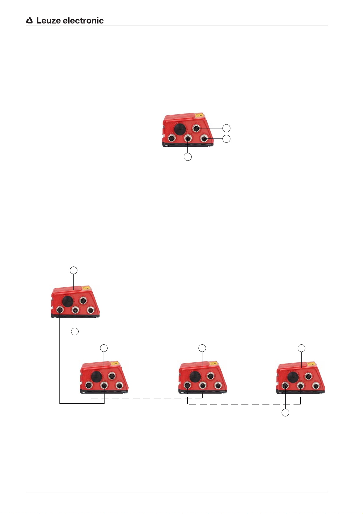
4.4 Stand-alone connection
The bar code readers of the BCL 600i series can be operated as single “stand-alone” devices. The device
features multiple M 12 connectors / sockets for the electrical connection of the supply voltage, the interface
and the switching inputs and outputs.
1 Switching inputs/outputs
2 Supply voltage
3 PC / PLC host interface
Figure 4.3: Stand-alone connection
Functions
1
2
3
4.5 Networking - Leuze multiNet plus
In the Leuze multiNet plus network, up to 32 bar code readers can be networked together. The respective
network devices transmit the read data when requested to by the BCL 600i (or MA 31) network master.
For this purpose, each device is assigned its own station address, which is set using the display of the
corresponding device.
The master then transmits the data of all network devices via its host interface to a superior PLC control
system or a computer, i.e. it “collects” the scanner data in the network and transmits it to an interface on
the host computer. This reduces interface costs (CPs) and time spent programming the software.
1
1
2
3 4 5
6
1 BCL 600i master
2 To PC/PLC
3 BCL 601i slave 1
4 BCL 601i slave 2
5 BCL 601i slave n
6 Terminating resistor on the last slave
Figure 4.4: Networking possibilities using the multiNet plus
Leuze electronic BCL 600i/BCL 601i 19
Two-wire RS 485
The Leuze multiNet plus is optimized for fast transmission of scanner data to a primary host computer. The
multiNet plus consists physically of a two-wire RS 485 interface through which the Leuze multiNet plus
software protocol is controlled. This makes wiring the network easy and inexpensive as slaves are looped
through to one another in parallel.
In principle, networking occurs via a parallel connection of the individual RS 485 interfaces of the respective bar code scanners. Shielded, twisted pair conductors should be used for the Leuze multiNet plus. This
allows a total network length of up to 1200m.
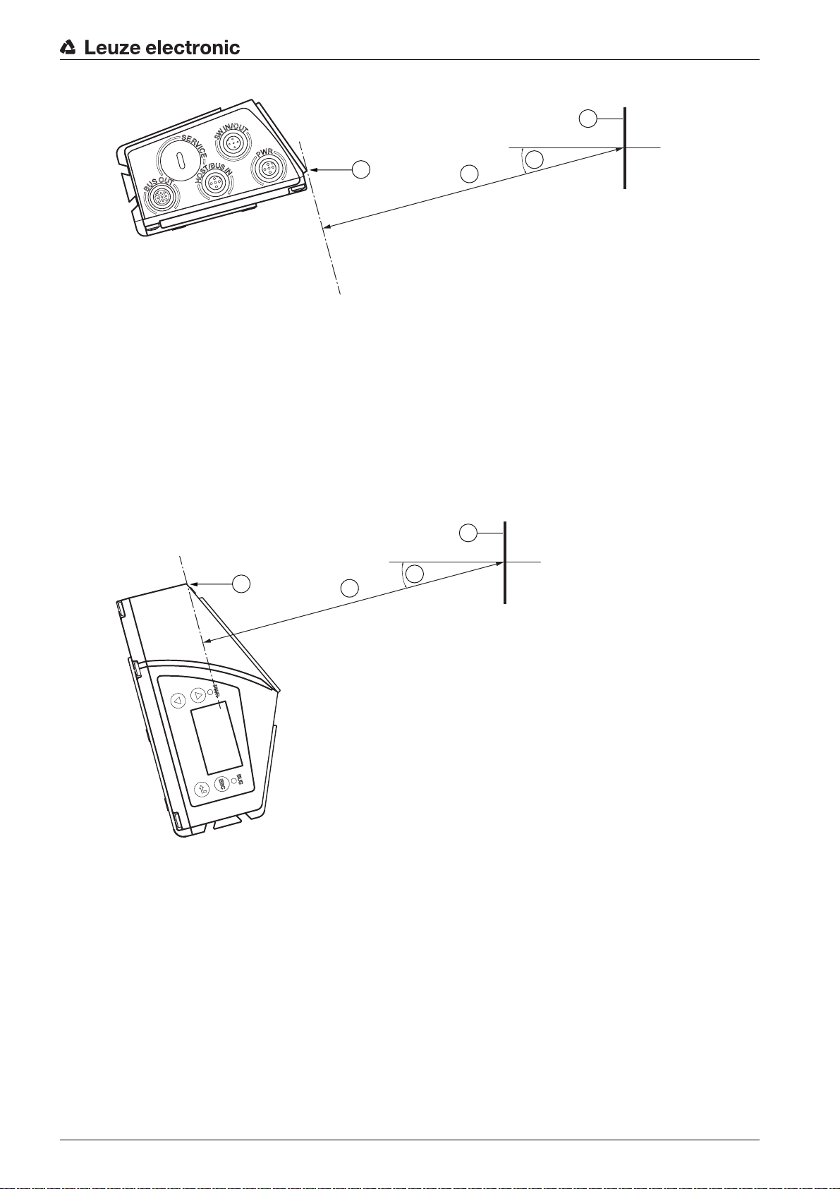
4.6 Leuze multiScan
The multiScan operating mode is based on Leuze multiNet plus and links individual bar code readings from
multiple bar code scanners into a single decoding result. This is used, for example, on a packet conveyor
system on which the label can be affixed on either the right or left side, thereby requiring two read stations.
To prevent the host from having to always process two readings for a single packet, i.e. a decoding result
and a No Read, a multiScan arrangement is used which transmits only one reading from the two read
stations to the host; this single reading is transmitted by the multiScan master.
Thus, from the perspective of the host, the scanner network appears to be just a single bar code
reader!
Functions
For this purpose one multiScan master and one or more multiScan slaves are connected together via the
RS 485 interface.
Figure 4.5: Scanner arrangement with the multiScan function
The multiScan function on the RS 485 interface is possible for minimum of 2 and a maximum of
32 devices!
The protocol set on the RS 485 interface is the multiNet protocol. As a result, during multiScan operation
on the RS 485 interface, the multiNet master also functions as the multiScan master and the
multiNet slaves function as multiScan slaves (thus, all multiNet slave are included in multiScan operation).
4.7 Heater
For low-temperature applications to min. -35°C (e.g. in cold storage), the bar code readers of the BCL 600i
series can optionally be permanently fitted with a built-in heating and these bar code readers purchased
as separate device models.
Leuze electronic BCL 600i/BCL 601i 20
5 Reading techniques
5.1 Line scanner (single line)
A line (scan line) scans the label. Due to the opt. opening angle, the reading field width is dependent on
the read distance. Through the movement of the object, the entire bar code is automatically transported
through the scan line.
The integrated code reconstruction technology permits twisting of the bar code (tilt angle) within certain
limits. These are dependent on the transport speed, the scanning rate of the scanner and the bar code
properties.
Areas of application of the line scanner
The line scanner is used:
• when the bars of the bar code are printed in the conveying direction ('ladder arrangement').
• with bar codes having very short bar lengths.
• when the ladder code is turned out of the vertical position (tilt angle).
• when the reading distance is large.
Reading techniques
Figure 5.1: Deflection principle for the line scanner
5.2 Line scanner with oscillating mirror
The oscillating mirror deflects the scan line additionally to both sides across the scan direction at a
randomly adjustable oscillation frequency. In this way, the device can also scan larger areas or spaces for
bar codes. The reading field height (and the scan line length useful for evaluation) depends on the reading
distance due to the optical opening angle of the oscillating mirror.
Leuze electronic BCL 600i/BCL 601i 21
Reading techniques
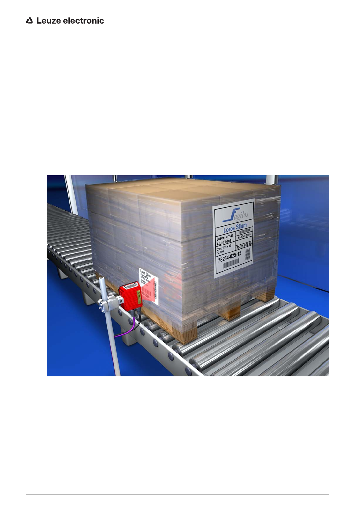
Areas of application of the line scanner with oscillating mirror
For line scanners with oscillating mirror, oscillation frequency, start/stop position etc. are adjustable. It is
used:
• when the position of the label is not fixed, e.g. on pallets – various labels can, thus, be detected at
various positions.
• when the bars of the bar code are printed perpendicular to the conveying direction (“picket fence
arrangement”).
• when reading stationary objects.
• when the bar code is turned out of the horizontal position.
• when the reading distance is large.
• when a large reading field (reading window) has to be covered.
Figure 5.2: Deflection principle for the line scanner with oscillating mirror add-on
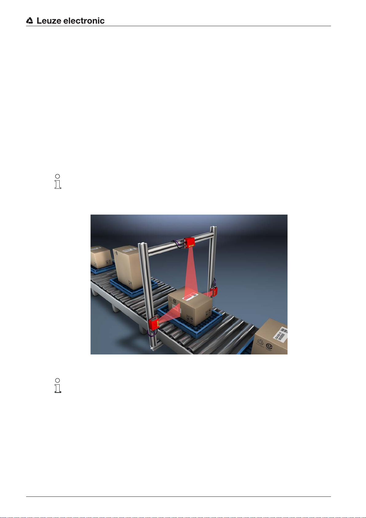
5.3 Omnidirectional reading
In order to read arbitrarily oriented bar codes on an object, at least 2 bar code readers are necessary. If
the bar code is not printed over-square, i.e. bar length > code length, bar code readers with integrated code
reconstruction technology are necessary.
Leuze electronic BCL 600i/BCL 601i 22
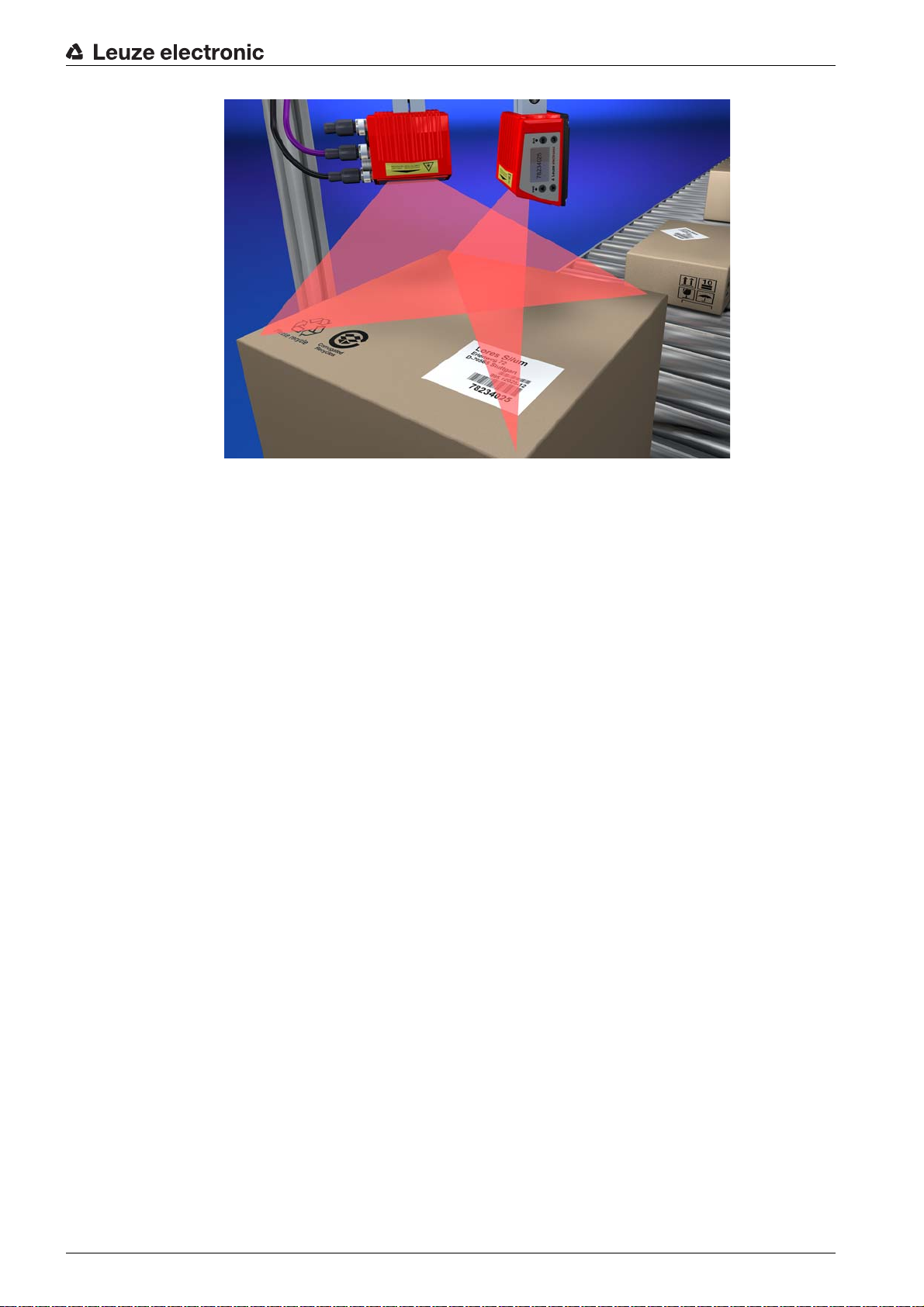
Figure 5.3: Principle arrangement for omnidirectional reading
Reading techniques
Leuze electronic BCL 600i/BCL 601i 23
6 Mounting
The bar code readers can be mounted in different ways:
• Using two M4x6 screws on the rear of the device or using four M4x6 screws on the bottom of the
device (see figure 3.2).
• Using a BT 56 mounting device on the two fastening grooves (see figure 15.3).
• Using a BT 59 mounting device on the two fastening grooves (see figure 15.4).
6.1 Device arrangement
6.1.1 Selecting a mounting location
In order to select the right mount
• Size, orientation, and position tolerance of the bar codes on the objects to be scanned.
• The reading field of the device in relation to the bar code module width.
• The resulting minimum and maximum reading distance from the respective reading field (see
chapter 15.5 "Reading field curves / optical data").
• The permissible cable lengths between the device and the host system depending on which interface
is used.
• The correct time for data output. The device should be positioned in such a way that, taking into consideration the time required for data processing and the conveyor belt speed, there is sufficient time
to e.g. initiate sorting operations on the basis of the read data.
• The display and control panel should be very visible and accessible.
• For configuring and commissioning with the webConfig tool, the USB interface should be easily
accessible.
• Maintaining the required environmental conditions (temperature, humidity).
• Possible soiling of the reading window due to liquids, abrasion by boxes, or packaging material residues.
• Lowest possible chance of damage to the device by mechanical collision or jammed parts.
• Possible extraneous light (no direct sunlight or sunlight reflected by the bar code).
Mounting
ing location, several factors must be considered:
With the line scanner, the beam exits the device parallel to the housing base; with the oscillating
mirror, the beam exits perpendicular to the housing base. The housing base is the black surface.
The best read results are obtained when:
• The device is mounted in such a way that the scanning beam is incident on the bar code at an angle
of inclination greater than ±10° … 15° to vertical.
• The reading distance lies in the middle area of the reading field.
• The bar code labels are of good print quality and have good contrast ratios.
• You do not use high-gloss labels.
• There is no direct sunlight.
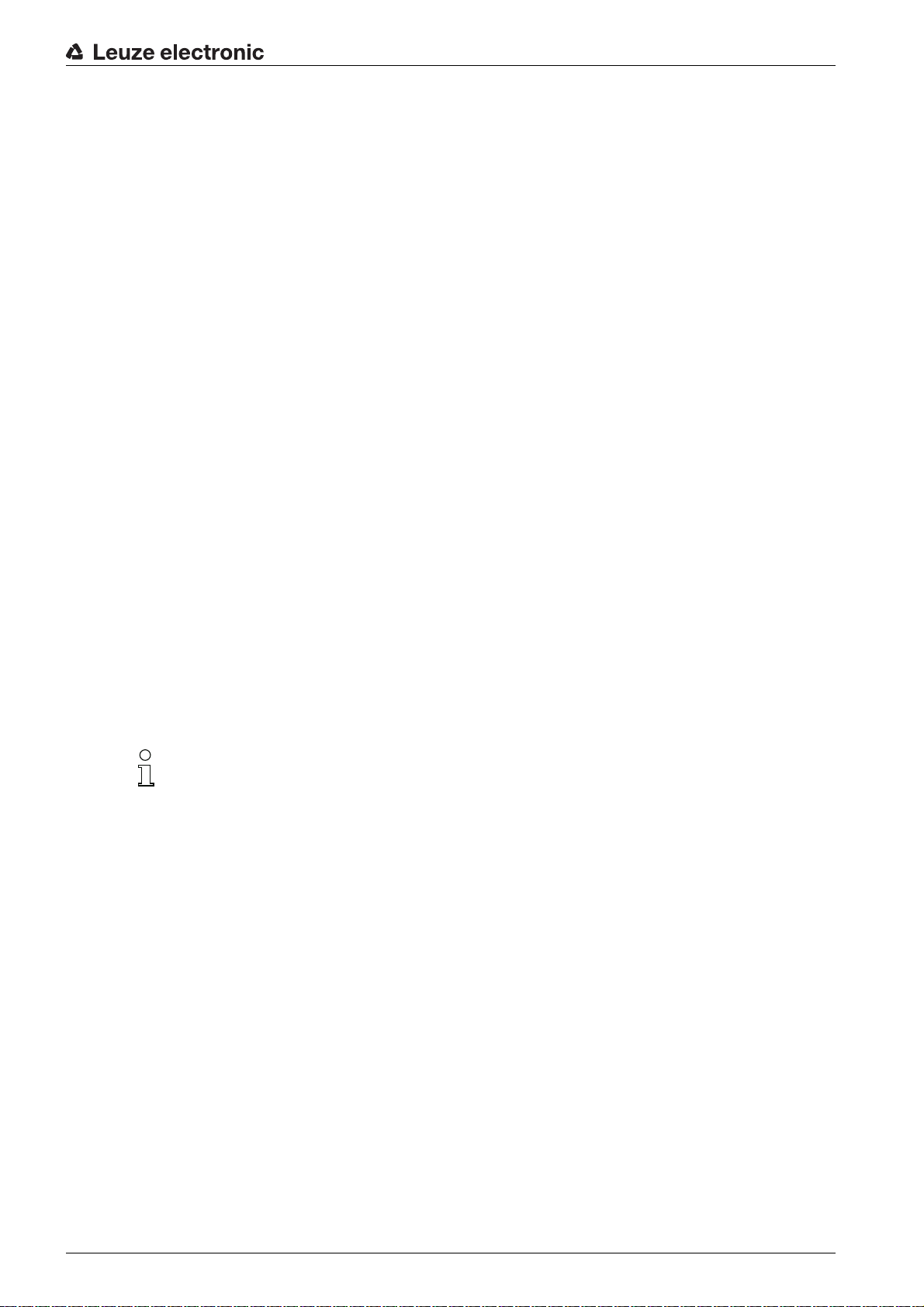
6.1.2 Avoiding total reflection – Line scann
The bar code label must be positioned at an angle of inclination greater than ±10° … 15° from vertical in
order to avoid total reflection of the laser beam (see figure 6.1)!
Total reflection occurs whenever the laser light of the bar code reader is directly incident on the surface of
the bar code at an angle of 90°. The light directly reflected by the bar code may overload the bar code
reader and thereby cause non-readings!
er
Leuze electronic BCL 600i/BCL 601i 24
1 Zero position
x
1
2
x
1
2
2Bar code
x Distance acc. to reading field curves
±10 … 15°
Figure 6.1: Total reflection – line scanner
6.1.3 Avoiding total reflection – oscillating-mirror scanner
Mounting
For the device with oscillating mirror, the l
aser beam exits at an angle of 90° to vertical.
In addition, the swivel range of ±20° is to be taken into account.
This means that in order to be on the safe side and to avoid total reflection, the device with oscillating mirror
must be inclined upward or downward 20° … 30°!
1 Zero position
2Bar code
x Distance acc. to reading field curves
±25°
Figure 6.2: Total reflection – oscillating-mirror scanner
6.1.4 Possible read angles betwee
n device and bar code
The optimum alignment of the device is accomplished when the scan line scans the bar code bars almost
at a right angle (90°). All reading angles that are possible between the scan line and bar code must be
taken account (see figure 6.3).
Leuze electronic BCL 600i/BCL 601i 25
Mounting
Azimuth angle (tilt)
Inclination angle (pitch)
Angle of rotation (skew)
In order to avoid total reflection, the skew should be greater than 10 °
Figure 6.3: Reading angle for the line scanner
6.2 Installing the external parameter memory
Remove the cover of the USB connection on the device.
Insert the USB memory stick into the USB connection and then cover it with the connector hood to
ensure degree of protection IP 65.
The USB memory stick can be inserted regardless of whether or not the device is connected to supply
voltage.
• After the USB memory stick has been inserted and supply voltage applied, the following message
appears on the display.
Memory stick connected: Export internal configuration?
Use the navigation buttons to select OK and activate with the enter button .
The configuration is now transferred to the external parameter memory and is from now on updated immediately when the configuration is changed via display or online commands.
• The display of MS under the device address indicates that the USB memory stick is correctly connected and functional.
Replacing a defective device
Uninstall the defective device.
Remove the external parameter memory from the defective device by unscrewing the protection hood.
Mount the external parameter memory on the new device.
Install and start up the new device.
The following message appears on the display again:
• Memory stick connected: Export internal configuration?
Leuze electronic BCL 600i/BCL 601i 26
Mounting
Use the navigation buttons to select Cancel and activate with the enter button .
Make sure you select Cancel. Otherwise, the configuration in the external parameter memory is
lost!
The configuration is now imported from the external parameter memory and the device is immediately
operational without any further configuration.
Leuze electronic BCL 600i/BCL 601i 27
7 Electrical connection
3 4 5
2
1
CAUTION
Do not open the device yourself under any circumstances! There is otherwise a risk of uncontrolled
emission of laser radiation from the device. The housing of the device contains no parts that need to
be adjusted or maintained by the user.
Before connecting the device, be sure that the supply voltage agrees with the value printed on the
name plate.
Connection of the device and cleaning must only be carried out by a qualified electrician.
Ensure that the functional earth (FE) is connected correctly. Unimpaired operation is only guaranteed
when the functional earth is connected properly.
If faults cannot be cleared, the device should be switched off and protected against accidental use.
CAUTION
For UL applications, use is only permitted in Class 2 circuits in accordance with the NEC (National
Electric Code). The bar code readers are designed in accordance with protection class III for supply by
PELV (protective extra-low voltage with reliable disconnection).
Electrical connection
CAUTION
Degree of protection IP 65 is achieved only if the connectors and caps are screwed into place!
7.1 Overview
As a “stand-alone” device, or multiNet plus “master” participant or network slave participant, the device is
equipped with four M 12 plugs/sockets which are A- and B-coded.
The voltage supply (PWR) as well as the four freely configurable switching inputs/outputs (SW IN/OUT and
PWR) are connected there.
An RS 232 or optionally RS 422 interface is available as “HOST / BUS IN” interface for connecting to the
host system. An RS 485 is available as a second physical “BUS OUT” interface for setting up the
Leuze multiNet plus scanner network. The device is suitable for use in the Leuze multiNet plus as network
master/multiScan master.
An USB connection is used as a SERVICE interface.
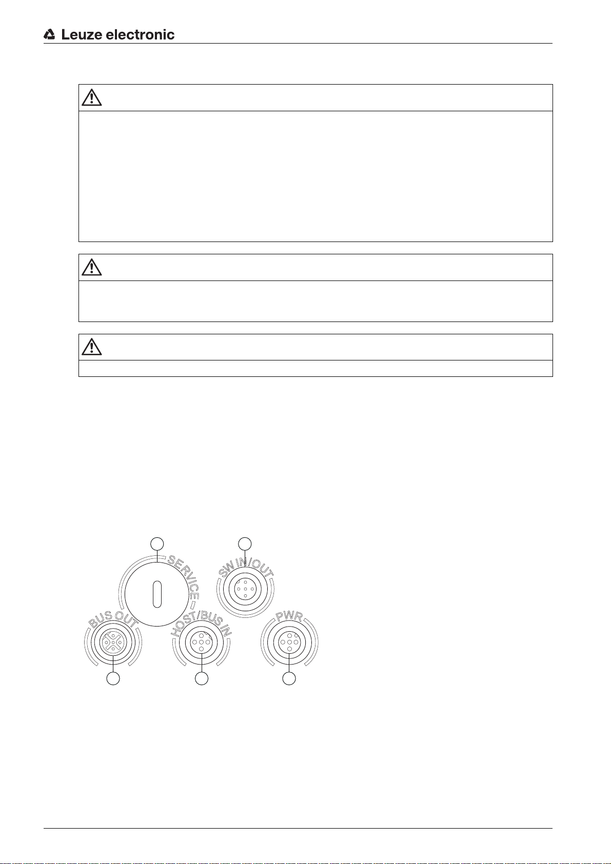
1 Service, USB socket, type A
2 SW In/Out, M 12 socket (A-coded)
3 Bus Out RS 485, M 12 socket (B-coded)
4 HOST/BUS in, M 12 connector (B-coded)
5 PWR, M 12 connector (A-coded)
Figure 7.1: Connections of the device
Described in detail in the following are the individual connections and pin assignments.
Leuze electronic BCL 600i/BCL 601i 28
7.2 PWR – Voltage supply and switching inputs/outputs 3 and 4
2
3
1
4
5
FE
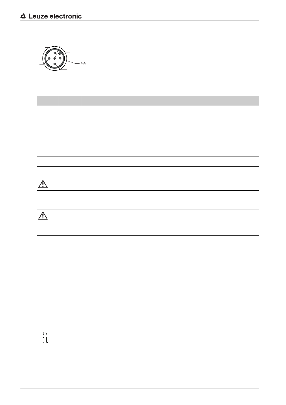
Figure 7.2: PWR, M 12 connector (A-coded)
Table 7.1: Pin assignments - PWR
Pin Name Comment
1 VIN Positive supply voltage +10 ... +30 V DC
2 SWIO_3 Configurable switching input / output 3
3 GND Negative supply voltage 0 V DC
4 SWIO_4 Configurable switching input / output 4
5 FE Functional earth
Electrical connection
Thread FE Functional earth (housing)
Supply voltage
CAUTION
For UL applications, use is only permitted in Class 2 circuits in accordance with the NEC (National
Electric Code).
CAUTION
The bar code readers of the BCL 600i series are designed in accordance with protection class III for
supply by PELV (protective extra-low voltage with reliable disconnection).
Connecting functional earth FE
Ensure that the functional earth (FE) is connected correctly. Unimpaired operation is only guaranteed
when the functional earth is connected properly. All electrical disturbances (EMC couplings) are discharged via the functional earth connection.
Switching input/output
The device is equipped with four freely programmable, opto-decoupled switching inputs and outputs
SWIO_1 … SWIO_4.
The switching inputs can be used to activate various internal functions of the device (decoding, autoConfig,
…). The switching outputs can be used to signal the state of the device and to implement external functions
independent of the superior control.
The two switching inputs/outputs SWIO_1 and SWIO_2 are located on the SW IN/OUT M 12 socket (see
chapter 7.4). The other two (SWIO_3 and SWIO_4) of the four freely configurable switching inputs/outputs
are located on the PWR M 12 connector.
The respective function as input or output can be set via the display or with the aid of the
“webConfig” configuration tool!
The external wiring as switching input and switching output is described in the following. For the respective
function assignment to the switching inputs/outputs see chapter 10.
Leuze electronic BCL 600i/BCL 601i 29
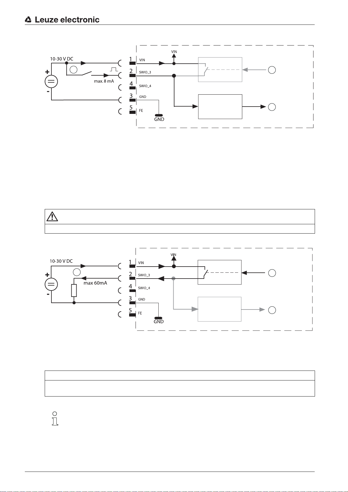
Function as switching input
1
2
3
Electrical connection
1
2
3
1 Switching input
2 Switching output from controller (deactivated)
3 Switching input to controller
Figure 7.3: Switching input connection diagram SWIO_3 and SWIO_4
If you use a sensor with a standard M 12 connector, please note the following:
Pins 2 and 4 must not be operated as switching outputs if sensors which function as inputs are also
connected to these pins.
If, for example, the inverted sensor output is connected to pin 2, and pin 2 of the bar code reader is, at
the same time, configured as an output (and not as an input), the switching output malfunctions.
CAUTION
The maximum input current must not exceed 8 mA!
Function as switching output
1 Switching output
2 Switching input from controller
3 Switching output to controller (deactivated)
Figure 7.4: Switching output connection diagram SWIO_3 / SWIO_4
NOTICE
Each configured switching output is short-circuit proof! Do not load the respective switching output of the
device with more than 60 mA at +10 … +30 V DC in normal operation!
By default, the two switching inputs/outputs SWIO_3 and SWIO_4 are configured so that switch-
ing input SWIO_3 activates the reading gate and switching output SWIO_4 switches on
“No Read”.
Leuze electronic BCL 600i/BCL 601i 30
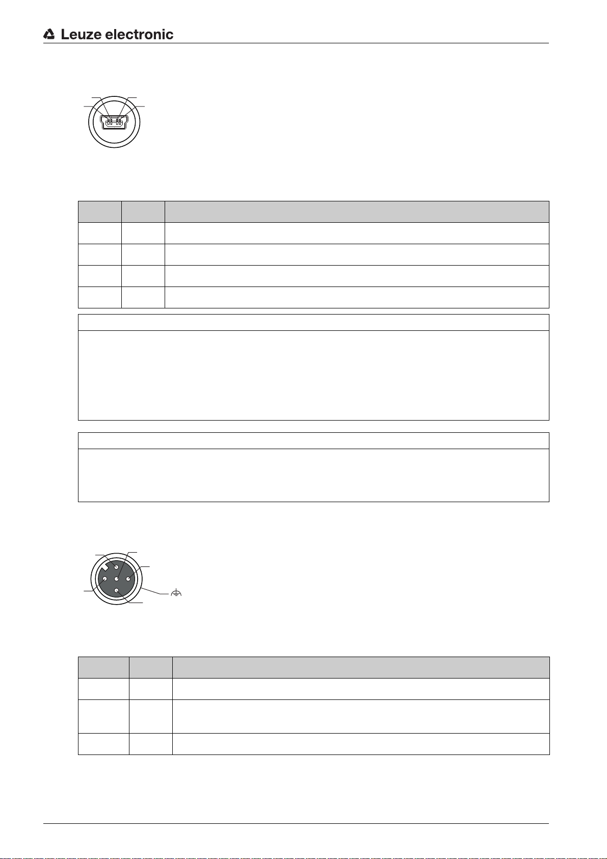
7.3 SERVICE – USB interface (type A)
4
3
1
2
1
3
2
4
5
FE
Figure 7.5: Service, USB, type A
Table 7.2: Pin assignments of SERVICE – USB interface
Pin Name Comment
1 VB Positive supply voltage +5 V DC
2 D- Data -
3 D+ Data +
4 GND Ground
NOTICE
Maximum load of the +5 V DC supply voltage of the USB interface is 200 mA!
Ensure adequate shielding.
The entire interconnection cable must absolutely be shielded acc. to the USB specifications. Cable
length must not exceed 3 m.
Use the Leuze-specific USB service cable (see chapter 16 "Ordering information and accessories") for
the connection and use a service PC to configure.
Electrical connection
NOTICE
IP 65 is achieved only if the connectors and caps are screwed into place. Alternatively, a parameter
memory in the form of a USB memory stick certified by Leuze electronic GmbH + Co. can be connected
to the provided USB service interface. With this Leuze memory stick, degree of protection IP 65 is also
ensured.
7.4 SW IN/OUT – Switching input/switching output
Figure 7.6: SW IN/OUT, M 12 socket (A-coded)
Table 7.3: Pin assignment SW IN/OUT
Pin Name Comment
1 VOUT Voltage supply for sensor system (VOUT identical to VIN at PWR IN)
2SWIO_
1
Configurable switching input / output 1
3 GND GND for the sensor system
Leuze electronic BCL 600i/BCL 601i 31

Pin Name Comment
1
2
3
4
Electrical connection
4SWIO_
Configurable switching input / output 2
2
5 FE Functional earth
Thread FE Functional earth (housing)
The device is equipped with four freely programmable, opto-decoupled switching inputs and outputs
SWIO_1 … SWIO_4.
The two switching inputs/outputs SWIO_1 and SWIO_2 are located on the SW IN/OUT M 12 socket. The
other two (SWIO_3 and SWIO_4) of the four freely configurable switching inputs/outputs are located on
the PWRsee chapter 7.4 M 12 connector.
The external wiring as switching input and switching output is described in the following. For the respective
function assignment to the switching inputs/outputs see chapter 10.
Function as switching input
1 Output
2 Switching output from controller (deactivated)
3 Switching input to controller
4 Diffuse reflection sensor
Figure 7.7: Switching input connection diagram SWIO_1 and SWIO_2
NOTICE
If you use a sensor with a standard M 12 connector, please note the following: Pins 2 and 4 must not be
operated as switching outputs if sensors which function as inputs are also connected to these pins. If, for
example, the inverted sensor output is connected to pin 2, and pin 2 of the bar code reader is, at the same
time, configured as an output (and not as an input), the switching output malfunctions.
NOTICE
The maximum input current must not exceed 8 mA!
Leuze electronic BCL 600i/BCL 601i 32

Function as switching output
3
1
2
4
FE
5
Electrical connection
1
2
3
1 Switching output
2 Switching output from controller
3 Switching input to controller (deactivated)
Figure 7.8: Switching output connection diagram SWIO_1 / SWIO_2
NOTICE
Each configured switching output is short-circuit proof! Do not load the respective switching output of the
device with more than 60 mA at +10 … +30 V DC in normal operation!
By default, the two switching inputs/outputs SWIO_1 and SWIO_2 are configured so that they
function as switching inputs. Switching input SWIO_1 activates the start reading gate function
and switching input SWIO_2 activates the reference code teach-in function.
The functions of the individual switching inputs/outputs are programmed via the display or via configuration
in the webConfig tool under the Switching input or Switching output heading (see chapter 10 "Starting up
the device - Configuration").
7.5 HOST / BUS IN
HOST / BUS IN for BCL 600i
The BCL 600i makes either the RS 232 or RS 422 interface available as host interface. This is selected
via the display or the “webConfig” configuration software. The pin assignments change depending on the
selected interface type (see table 7.4, see figure 7.10 and see figure 7.11).
Figure 7.9: HOST/BUS IN, M 12 connector (B-coded)
Table 7.4: Pin assignment HOST / BUS IN for BCL 600i
Pin Name Comment
1 CTS /
RX+
CTS signal (RS 232) / RX+ (RS 422)
2TxD /
TXD signal (RS 232) / TX- (RS 422)
Tx-
3 GND_H Reference potential 0V for RS 232 / RS 422
Leuze electronic BCL 600i/BCL 601i 33

Pin Name Comment
3
1
2
4
FE
5
Electrical connection
4RTS/
RTS signal (RS 232) / TX+ (RS 422)
Tx+
5 RxD /
RxD signal (RS 232) / Rx- (RS 422)
Rx-
Thread FE Functional earth (housing)
RS 232 interface
2
1
RXD
TXD
GND
CTS
RTS
GND_H
3
1Host
2Shield
3 Max. 10 m
Figure 7.10: Pin assignments - HOST / BUS IN as RS 232
RXD/RX-
TXD/TX-
3
5
RTS/TX+
2
CTS/RX+
1
4
NOTICE
Ensure adequate shielding. The entire interconnection cable must be shielded and earthed. The cables
for RTS and CTS must only be connected if RTS/CTS hardware handshake is used.
RS 422 interface
1
RX-
TX-
GND
RX+
TX+
2
TXD/TX-
2
GND_H
RXD/RX-
3
RTS/TX+
CTS/RX+
1
5
4
2
1Host
2 Twisted pair
Figure 7.11: Pin assignments - HOST / BUS IN as RS 422
NOTICE
Ensure adequate shielding. The entire interconnection cable must be shielded and earthed. The signal
lines must be stranded in pairs.
HOST / BUS IN for BCL 601i
The BCL 601i makes available an RS 485 as HOST / BUS IN interface for the connection to the host
system. This interface is physically looped through to the BUS OUT RS 485 socket.
With its RS 485 interface, the BCL 601i is suitable for use in the Leuze multiNet plus scanner network.
Leuze electronic BCL 600i/BCL 601i 34
Figure 7.12: HOST/BUS IN, M 12 connector (B-coded)

Table 7.5: Pin assignment HOST / BUS IN for BCL 601i
1
3
2
4
5
Pin Name Comment
1 N.C. Reserved
2 RS 485 BRS 485 B - signal line
Electrical connection
3GND
4 RS 485 ARS 485 A - signal line
5 FE Functional earth / shield
Thread FE Functional earth (housing)
7.6 BUS OUT
To set up the Leuze multiNet plus network with additional participants, the device makes available another
interface in the form of an RS 485.
Figure 7.13: M 12 socket (B-coded)
Table 7.6: Pin assignment BUS OUT
Pin Name Comment
Reference ground RS 485 - potential equalization
485
1 VCC485+5VDC for bus termination
2 RS 485 BRS 485 B - signal line
3GND
Reference ground RS 485 - potential equalization
485
4 RS 485 ARS 485 A - signal line
5 FE Functional earth / shield
Thread FE Functional earth (housing)
NOTICE
Ensure adequate shielding. The entire interconnection cable must be shielded and earthed. The signal
lines must be stranded in pairs.
Termination of the RS 485 interface on the master (BCL 600i)
The RS 485 interface must always be terminated externally on the master via a T-connector and a termi-
nating resistor (see chapter 16 "Ordering information and accessories").
Termination of the RS 485 interface on the slave (BCL 600i)
On the last network participant, the Leuze multiNet plus network (RS 485 interface) should be terminated
with a terminating resistor on the BUS OUT socket (see chapter 16 "Ordering information and accessories").
Leuze electronic BCL 600i/BCL 601i 35

The BCL 600i can only participate as a slave in the Leuze multiNet plus on the BUS OUT socket
and via an external M 12 T-connector (see chapter 7.8.3 and see figure ).
Termination of the RS 485 interface (BCL 601i)
The device operates as slave in the Leuze multiNet plus network. On the last physical participant, the
Leuze multiNet plus network (RS 485 interface) must be terminated with a terminating resistor (see
chapter 16 "Ordering information and accessories"). This prevents reflections on the Leuze multiNet plus
and improves the immunity to interference.
7.7 Cable lengths and shielding
Observe the following maximum cable lengths and shielding types:
Table 7.7: Cable lengths and shielding
Connection Interface Max. cable length Shielding
BCL – service USB 3 m Shielding absolutely
Electrical connection
necessary acc. to USB
specifications
BCL – host RS 232
Network from the first
BCL to the last BCL
BCL – power supply
unit
Switching input 10 m Not necessary
Switching output 10 m Not necessary
7.8 Leuze multiNet plus
The Leuze multiNet plus is optimized for fast transmission of scanner data to a primary host computer. The
multiNet plus consists physically of a two-wire RS 485 interface through which the multiNet plus software
protocol is controlled.
This makes wiring the network easy and inexpensive as slaves are looped through to one another in
parallel.
10 m
RS 422
RS 485
RS 485 1200 m shielding absolutely
1200 m
1200 m
30 m Not necessary
shielding absolutely
required
RS 422/485 conductors, stranded in pairs
required
RS 485 conductors,
stranded in pairs
Leuze electronic BCL 600i/BCL 601i 36

1
1
2
3 4 5
1 BCL 600i master
2 To PC/PLC
3 BCL 601i slave 1
4 BCL 601i slave 2
5 BCL 601i slave n
6 Terminating resistor on the last slave
Figure 7.14: Leuze multiNet plus system topology
Electrical connection
6
With the aid of a BCL 600i network master, up to 31 bar code readers can be networked. For this purpose,
each participating device is assigned the respective station address via the display and the control panel.
The devices are networked by connecting the individual RS 485 interfaces in parallel.
In the Leuze multiNet plus network, the individual network devices sequentially transfer their data to the
BCL 600i network master when requested.
The BCL 600i master then transmits the data of all network devices via its host interface (either an RS 232
or RS 422) to a superior PLC control or to a computer, i.e. it “collects” the scanner data in the network and
transmits it to an interface on the host computer. This reduces interface costs (CPs) and time spent
programming the software.
7.8.1 Wiring the multiNet plus
Leuze multiNet plus connection hints
Shielded, twisted pair conductors should be used for the Leuze multiNet plus. This allows a total network
length of up to 1200 m.
Recommended network cable (e.g. LiYCY 2x0.2 mm
• Twisted pairs, shielded
• Cross section: min. 0.2 mm
• Copper resistance <100 W/km
When wiring the network, note the following points:
The RS 485A, RS 485B and GND cables are looped through in the network and must not in any case
be misconnected; the Leuze multiNet plus network is otherwise not functional. It is recommended to wire
through the GND of the RS 485 interface of the participants.
Connect the shielding to the slaves on one side with FE.
The maximum cable length in the network is 1200m.
The (physically) last slave in the network should be equipped with a terminating resistor of 220
between RS 485A and RS 485B. This prevents reflections on the multiNet plus and improves the immunity to interference.
²
):
²
W
Leuze electronic BCL 600i/BCL 601i 37

Use the recommended connectors / sockets or the ready-made cables and terminating resistors
(see chapter 16 "Ordering information and accessories").
7.8.2 The BCL 600i as network master
Master operation
BCL 600i bar code readers are specially designed for master operation in a network. They manage
The
the data of the slaves in multiNet plus and establish the connection to the superior host computer. Only a
few parameters need to be set for master operation. Network commissioning can thus be performed in
very little time (see chapter 10 "Starting up the device - Configuration").
Last slave address
Unlike the slaves, the display of the BCL 600i is not used to set the network address (the master always
has the address 00), but the last slave address, i.e. the number of the most significant slave. This “informs”
the BCL 600i master of the number of slaves operating on the network, without requiring you to call up the
webConfig tool. If the network is expanded at a later time, you only need to change the number of slaves
(last slave address) accordingly via the display.
Start-up / timeout messages
During the initialization phase, i.e. after switching on the operating voltage, the master searches for the set
number of slaves. If a slave is found, the master generates a start-up message “S” for the respective
address found, e.g. “04S” -> Slave with the address 04 has responded correctly.
If a slave is not found or does not respond, the master generates a “timeout” (response timeout) at this
address.
The slave address and a “T” are output on the host interface. For example, “08T” means that no slave
responded at the network address 08. The network is still operational with one or several reported
“timeouts”, however, a slave, for which a timeout was generated, can no longer be addressed.
Electrical connection
BCL 600i master mounting location
Ensure that the BCL 600i is mounted in an easily accessible and visible place in your system. Once the
network has been put into operation, you can set (configure) every scanner in the network centrally via the
USB service or host interface of the BCL 600i, without having to connect a PC/terminal to the individual
read stations.
7.8.3 The BCL 600i as netwo
Alternatively, the bar code readers of the BCL 600i series can also operate as slave participants in the
network mode. They now transmit data to the multiNet master (e.g. BCL 600i) only after the master
prompts them to do so, and, using an external M 12 T-connector, they establish the continuing connection
via the BUS OUT socket to the slaves which follow (order information see chapter 16.3 "Accessories").
The last network participant must be terminated with a terminating resistor.
rk slave
Leuze electronic BCL 600i/BCL 601i 38

1
1
2
3 4 5
1 BCL 600i master
2 To PC/PLC
3 BCL 600i slave 1
4 BCL 600i slave 2
5 BCL 600i slave n
6 Terminating resistor on the last slave
Figure 7.15: Leuze multiNet plus system topology with BCL 600i as slave
Electrical connection
6
Only a few parameters need to be set for slave operation. Network commissioning can thus be performed
in very little time (see chapter 10 "Starting up the device - Configuration").
Slave address
The BCL 600i display has an important function for setting the network address. The network address, i.e.
the corresponding station number of the slave, is set via the display. The address which is set must be > 0
since the master always has address 0 (Adr.00).
Each network device with an address > 0 is thereby automatically informed that it is a slave in the
Leuze multiNet plus with this address and that it is initialized and queried by the network master. No other
settings are necessary for commissioning in the Leuze multiNet plus.
Other settings
The parameters necessary for the reading task, such as the code t y p es to be read and the number of di g i t s
of the code, must be set. This can be done via the display, as well as with the help of the webConfig tool.
7.8.4 The BCL 601i as network slave
The BCL 601i bar code readers are specially designed for slave operation in a network. They transmit data
to the multiNet master only after the master prompts it to do so and establish the continuing connection
via the BUS OUT socket to the slaves which follow. Only a few parameters need to be set for slave operation. Network commissioning can thus be performed in very little time (see chapter 10 "Starting up the
device - Configuration").
The connection is performed as described above (see figure 7.14).
Slave address
With the BCL 601i, the network address, i.e. the corresponding station number of the slave, is set via the
display. The address which is set must be > 0 since the master always has address 0 (Adr.00).
Each network device with an address > 0 is thereby automatically informed that it is a slave in the
Leuze multiNet plus with this address and that it is initialized and queried by the network master. No other
settings are necessary for commissioning in the Leuze multiNet plus.
Other settings
The parameters necessary for the reading task, such as the code t y p es to be read and the number of di g i t s
of the code, must be set. This can be done via the display, as well as with the help of the webConfig tool.
Leuze electronic BCL 600i/BCL 601i 39

8 Menu description
After voltage is applied to the bar code reader, a startup screen is displayed for several seconds. The
display then shows the bar code reading window with all status information.
8.1 The main menus
Use the navigation buttons to move through the menu. Activate the desired selection with the enter
button .
Device information This menu item contains detailed information on
Menu description
• Device type
• Software version
• Hardware version
• Serial number
Network settings
Bar code reading
window
Parameter
Language selection
Service
Actions
The display offers only limited configuration options. The configurable parameters are described
in this chapter. Only the webConfig tool provides complete configuration options and is largely
self-explanatory. For the use of webConfig tool see chapter 9. Notes on commissioning via the
webConfig tool see chapter 10.
8.2 Parameter menu
Parameter handling
The Parameter handling submenu is used to lock and release the parameter input via the display and for
resetting to default values.
• Display of the network settings
• Visualization of the read bar code information
• Status overview of the switching inputs/outputs
• Bar graphs for read quality of the current bar code.
Further information see chapter "Indicators in the display".
• Configuration of the bar code reader
Further information see chapter 8.2 "Parameter menu".
• Selection of the display language
Further information see chapter 8.3 "Language selection menu".
• Scanner diagnosis and status messages
Further information see chapter 8.4 "Service menu".
• Various functions for scanner configuration and manual operation
Further information see chapter 8.5 "Actions menu".
Table 8.1: Parameter handling submenu
Level 3 Level 4 Level 5 Selection/configuration option
Parameter enable OFF/ON
Parameters to default By pressing the enter button after selecting
Description
The standard setting (OFF) prevents unintended parameter
changes.
If parameter enabling is activated (ON), parameters can be
changed manually.
Parameters to default, all parameters are reset to their standard settings without any further security prompts.
In this case, English is selected as the display language.
Standard
OFF
Decoder table
In the Decoder table submenu, 4 different code type definitions can be stored. Bar codes that have been
read can only be decoded if they correspond to one of the definitions stored here.
Leuze electronic BCL 600i/BCL 601i 40

Table 8.2: Decoder table submenu
Menu description
Level 3 Level 4 Level 5 Selection/configuration option
Max. no. of
labels
Decoder 1 Symbology
(Code type)
Number of digits Interval mode OFF/ON
Number of digits 10 to 64 characters
Number of digits 20 to 64 characters
Number of digits 30 to 64 characters
Description
Value between 0 and 64
The value set here specifies the maximum number of labels that
should be detected for each reading gate.
No code
Code 2/5 Interleaved
Code 39
Code 32
Code UPC
Code EAN
Code 128
EAN Addendum
Codabar
Code 93
GS1 DataBar Omnidirectional
GS1 DataBar Limited
GS1 DataBar Expanded
If No code is configured, the current and all subsequent decoders
are deactivated.
With the ON setting, the values in digits 1 and 2 define a range of
character numbers that are to be read.
First decodable number of characters or lower range limit.
Second decodable number of characters or upper range limit.
Third decodable number of characters.
Standard
1
Code 2/5i
OFF
10
0
0
Number of digits 40 to 64 characters
Number of digits 50 to 64 characters
Reading reliability Value from 2 to 100
Check digit method Standard
Check digit transmission
Fourth decodable number of characters.
Fifth decodable number of characters.
Number or scans required to reliably detect a label.
No check
Depending on the symbology (code type) selected for the decoder,
further calculation algorithms can be selected here.
Check digit method used for the decoding of the bar code that has
been read.
If Standard is set, the check digit method intended for the respective code type is used.
Standard
Not standard
Specifies whether the check digit is transmitted. Standard means
that the transmission matches the standard intended for the
respective code type.
0
0
4
Standard
Standard
Leuze electronic BCL 600i/BCL 601i 41

Menu description
Level 3 Level 4 Level 5 Selection/configuration option
Decoder 2 Symbology Same as decoder 1 Code 39
Number of digits Interval mode OFF/ON ON
Number of digits 10 to 64 characters 4
Number of digits 20 to 64 characters 30
Number of digits 30 to 64 characters 0
Number of digits 40 to 64 characters 0
Number of digits 50 to 64 characters 0
Reading reliability Value from 2 to 100 4
Check digit method Same as decoder 1 Standard
Check digit transmission
Decoder 3 Symbology Same as decoder 1 Code 128
Number of digits Interval mode OFF/ON ON
Number of digits 10 to 64 characters 4
Description
Same as decoder 1 Standard
Standard
Number of digits 20 to 64 characters 63
Number of digits 30 to 64 characters 0
Number of digits 40 to 64 characters 0
Number of digits 50 to 64 characters 0
Reading reliability Value from 2 to 100 4
Check digit method Same as decoder 1 Standard
Check digit transmission
Decoder 4 Symbology Same as decoder 1 Code UPC
Number of digits Interval mode OFF/ON OFF
Number of digits 10 to 64 characters 8
Number of digits 20 to 64 characters 0
Number of digits 30 to 64 characters 0
Number of digits 40 to 64 characters 0
Same as decoder 1 Standard
Number of digits 50 to 64 characters 0
Reading reliability Value from 2 to 100 4
Check digit method Same as decoder 1 Standard
Check digit transmission
Same as decoder 1 Standard
Leuze electronic BCL 600i/BCL 601i 42

Menu description
Digital SWIO
The Digital SWIO submenu is used to configure the 4 switching inputs/outputs of the device.
Table 8.3: Digital SWIO submenu
Level 3 Level 4 Level 5 Selection/configuration option
Sw. input/output 1 I/O mode Input / Output / Passive
Switching input Inverted OFF / ON
Debounce time Value from 0 to 1000
Start-up delay Value from 0 to 65535
Pulse duration Value from 0 to 65535
Switch-off delay Value from 0 to 65535
Function No BCL600i function
Description
Determines the function of switching input/output 1.
In the case of passive, the connection is on 0 V if the
Inverted parameter is set to OFF, and on +UB if the
Inverted parameter is set to ON.
OFF = activation of the switching input function upon high
level at the switching input
ON = activation of the switching input function upon low
level at the switching input
Time in milliseconds for which the input signal must be
present and stable.
Time in milliseconds between the end of the debounce
time and activation of the function configured below.
Minimum activation time in milliseconds for the function
configured below.
Time in milliseconds for which the function configured
below remains activated after the switching input signal is
deactivated and the pulse duration has expired.
Reading gate start/stop
Reading gate stop
-Reading gate start
Teach reference code
Autoconfig start/stop
The function set here is carried out after the switching input
is activated.
Standard
Input
OFF
5
0
0
0
Reading gate
start/stop
Leuze electronic BCL 600i/BCL 601i 43

Menu description
Level 3 Level 4 Level 5 Selection/configuration option
Switching output Inverted OFF / ON
Signal delay Value from 0 to 65535
Pulse duration Value from 0 to 65535
Activation function 1 No function
Description
OFF = activated switching output upon high level
ON = activated switching output upon low level
Time in milliseconds between activation function and
switching of the switching output.
Switch-on time of the switching output in milliseconds. If
the Pulse duration is set to 0, the switching output is
switched on via the Activation function and switched off via
the Deactivation function.
If the Pulse duration is greater than 0, the Deactivation
function has no effect.
Reading gate start
Reading gate end
Positive reference code comparison 1
Negative reference code comparison 1
Valid read result
Invalid read result
Device ready
Device not ready
Data transmission active
Data transmission not active
AutoCont. good quality
AutoCont. bad quality
Reflector detected
Reflector not detected
External event, pos. edge
External event, neg. edge
Device active
Device standby
No device error
Device error
Positive reference code comparison 2
Negative reference code comparison 2
The function set here specifies which event activates the
switching output.
Standard
OFF
0
400
No function
Deactivation function 1 See Activation function 1 for selection options
Sw. input/output 2 I/O mode Input / Output / Passive Output
Switching input Inverted OFF / ON OFF
Debounce time Value from 0 to 1000 5
Start-up delay Value from 0 to 65535 0
Pulse duration Value from 0 to 65535 0
Switch-off delay Value from 0 to 65535 0
Function See switching input/output 1 No function
Switching output Inverted OFF / ON OFF
Signal delay Value from 0 to 65535 0
Pulse duration Value from 0 to 65535 400
Activation function 2 See switching input/output 1 Valid read result
Deactivation function 2 See switching input/output 1 Reading gate
The function set here specifies the event that deactivates
the switching output.
No function
start
Leuze electronic BCL 600i/BCL 601i 44

Menu description
Level 3 Level 4 Level 5 Selection/configuration option
Sw. input/output 3 I/O mode Input / Output / Passive Input
Switching input Inverted OFF / ON OFF
Debounce time Value from 0 to 1000 5
Start-up delay Value from 0 to 65535 0
Pulse duration Value from 0 to 65535 0
Switch-off delay Value from 0 to 65535 0
Function See switching input/output 1 Reading gate
Switching output Inverted OFF / ON OFF
Signal delay Value from 0 to 65535 0
Pulse duration Value from 0 to 65535 400
Activation function 3 See switching input/output 1 No function
Deactivation function 3 See switching input/output 1 No function
Sw. input/output 4 I/O mode Input / Output / Passive Output
Switching input Inverted OFF / ON OFF
Debounce time Value from 0 to 1000 5
Description
Standard
start/stop
Start-up delay Value from 0 to 65535 0
Pulse duration Value from 0 to 65535 0
Switch-off delay Value from 0 to 65535 0
Function See switching input/output 1 No function
Switching output Inverted OFF / ON OFF
Signal delay Value from 0 to 65535 0
Pulse duration Value from 0 to 65535 400
Activation function 4 See switching input/output 1 Invalid read
Deactivation function 4 See switching input/output 1 Reading gate
Table 8.4: Com submenu
Level 3 Level 4 Level 5 Selection/configuration option
Operating mode Stand-alone device
HOST / BUS IN Protocol type No protocol
Description
Network Master
Network Slave
Framing protocol
Framing protocol with acknowledgment
muliNet Slave
multiNet Master
result
start
Standard
Stand-alone
device
Framing protocol
Interface Baud rate 110 ... 115200 Baud 9600
Leuze electronic BCL 600i/BCL 601i 45

Menu description
Level 3 Level 4 Level 5 Selection/configuration option
Data format 7N1
Handshake None
Standard RS232
Framing proto-
a)
col
RX Prefix 1 … 3
TX Prefix 1 … 3
Description
7N2
7E1
7E2
7O1
7O2
8N1
8N2
8E1
8E2
8O1
8O2
9N1
The data format is specified in:
Number of bits (7,8,9)
Parity (N=none, E=even, O=odd)
Number of stop bits (1,2)
RTS CTS
XON XOFF
RS422
RS485
b)
Postfix 1 ... 3
BCC mode
Control character definition for transmit data
Postfix 1 ... 3
BCC mode
Control character definition for received data
Standard
8N1
None
RS232
STX, NULL,
NULL
CR, LF, NULL
None
STX, NULL,
NULL
CR, LF, NULL
None
Address format No address
Address Value from 0 to 31 0
BUS OUT multiNet Master Maximum num-
multiNet Slave Slave address Value from 0 to 31
ber of slaves
a) If the device is configured as stand-alone device or network master, the framing protocol defines how data is exchanged
between the BCL 600i and the host. The framing protocol is a characte r-b ase d pr oto col for the tra nsm iss ion of ASCI I
characters. It groups the characters to be transmitted into a datablock and frames the block with control characters. Var-
ious block checking methods are optionally available for protecting the integrity of the data.
b) Enter the decimal value of the desired ASCII character here. For example, enter "13" for the "CR" character (Carriage
Return) (see chapter 18.1).
8.3 Language selection menu
Currently, there are 6 display languages available:
• German
• English
• Spanish
• French
• Italian
• Chinese
The display language and the language of the webConfig user interface are synchronized. The setting in
the display affects the webConfig tool and vice versa.
Binary address
ASCII address
Automatic address
Value from 0 to 31
If the BCL 600i was configured as network master in the Operating mode
menu item, the maximum number of slaves managed by the master must
be entered here.
If the BCL 600i was configured as network slave in the Operating mode
menu item, the slave address must be entered here.
No address
1
1
Leuze electronic BCL 600i/BCL 601i 46

8.4 Service menu
Diagnostics
This menu item is used exclusively for service purposes by Leuze electronic.
Status messages
This menu item is used exclusively for service purposes by Leuze electronic.
8.5 Actions menu
Start decoding
Here, you can perform a single reading via the display.
Activate the single reading with the enter button and hold a bar code in the reading field of the device.
The laser beam is switched on and the following display appears:
zzzzzzzzz
Once the bar code is detected, the laser beam is switched off again. The read result zzzzzzzzz is shown
directly in the display for about 1 s. After that, the Actions menu is displayed again.
Start alignment
The alignment function makes it easy to align the device by optically displaying the read quality.
Activate the alignment function with the enter button and hold a bar code in the reading field of the
device.
At first, the laser beam is switched on continuously, enabling you to position the bar code securely in the
reading field. Once the bar code is read, the laser beam is switched off briefly and the following display
appears:
Menu description
xx zzzzzz
xx Read quality in % (scans with info)
zzzzzz Contents of the decoded bar code
Once the bar code has been detected, the laser beam starts to flash.
The flash frequency provides visual information on the read quality. The faster the laser beam flashes, the
higher the read quality.
Start auto-setup
The auto-setup function provides an easy option for configuring the code type and number of digits of
Decoder 1.
Use the enter button to activate the auto-setup function and hold an unknown bar code in the reading
beam of the device.
The following display appears:
xx yy zzzzzz
The following information is displayed:
xx Code type of the detected code (sets the code type of Decoder 1)
01 2/5 Interleaved
02 Code 39
06 UPC (A, E)
07 EAN
Leuze electronic BCL 600i/BCL 601i 47

Menu description
08 Code 128, EAN 128
10 EAN Addendum
11 Codabar
yy Number of digits of the detected code (sets the number of digits of Decoder 1)
zzzzzz Contents of the decoded label. A appears if the label was not correctly read.
Start teach-in
The teach-in function can be used to conveniently read reference code 1.
Use the enter button to activate the teach-in function and hold a bar code which contains the content
that you wish to store as the reference code in the reading beam of the device.
The following display appears:
RC13xxzzzzzz
RC13 Means that ReferenceCode number 1 is stored in RAM. This is always output
xx Defined code type (see auto-setup)
z Defined code information (1 … 63 characters)
8.6 Operation
Shown here is an example describing important operating procedures in detail.
Parameter enable
During normal operation parameters can only be viewed. If parameters need to be changed, the ON menu
item in the Parameter enabling menu must be activated.
Use the navigation buttons to move through the menu. Activate the desired selection with
the enter button .
In the Parameter menu, select Parameter handling.
Press the enter button to enter the menu.
Select the Parameter enable menu item.
Press the enter button to enter the menu.
Select the ON menu item.
Press the enter button to enter the menu.
The PWR LED lights up red. You can now set individual parameters via the display.
Press the Escape button twice to return to the main menu.
Network configuration
For information on network configuration see chapter 10 "Starting up the device - Configuration".
Leuze electronic BCL 600i/BCL 601i 48

Commissioning – Leuze electronic webConfig tool
9 Commissioning – Leuze electronic webConfig tool
With the Leuze webConfig tool, an operating-system independent, web-technology based, graphical user
interface is available for configuring bar code readers of the BCL 600i series.
Through the use of HTTP as communication protocol and by using only standard technologies on the client
side (HTML, JavaScript and AJAX), which are supported by all commonly used, modern browsers (e.g.
Mozilla Firefox beginning with Version 4, Internet Explorer beginning with Version 8.0 and Microsoft Edge),
it is possible to operate the Leuze webConfig tool on any internet-ready PC.
9.1 Connecting the service USB interface
The connection to the SERVICE USB interface of the device is established via the PC-side USB interface
using a special USB cable with 2 type A/A plugs.
9.2 Installation
9.2.1 System requirements
Operating system:
indows 2000
W
Windows XP (Home Edition, Professional)
Windows Vista
Windows 7
Windows 8
Windows 10
Computer:
PC with USB interface version 1.1 or higher
Graphics card:
Min. 1024 x 768 pixels or higher resolution
Required disk capacity:
Approx. 10 MB
It is recommended to update the operating system regularly and to install the current Windows
service packs.
9.2.2 Installing the USB driver
In order for the device to be automatically detected by the connected PC, the USB driver must be installed
once on your PC. To do this, you must have administrator privileges.
Please proceed according to the following steps.
Start your PC with administrator privileges and log on.
Load the CD included in the delivery contents of your device in the CD drive and start the setup.exe
program.
Alternatively, you can also download the setup program from the internet at www.leuze.com.
Follow the instructions provided by the setup program.
Upon successful installation of the USB driver, an icon automatically appears on the desktop.
To check: In the Windows device manager, a device called “Leuze electronic, USB Remote NDIS N etwork
Device” appears under the “Network adapter” device class following successful USB registration.
If the installation failed, contact your network administrator: The settings of the firewall used may
need to be adjusted.
Leuze electronic BCL 600i/BCL 601i 49

9.3 Starting the webConfig tool
To start the webConfig tool, click the icon located on the desktop. Make certain that the device is
connected to the PC via the USB interface and that voltage is connected.
Or alternatively: Open a browser on your PC and enter the following address: 192.168.61.100.
This is the default Leuze service address for communication with bar code readers of the BCL 600i series.
In both cases, the following start page appears on your PC.
Commissioning – Leuze electronic webConfig tool
Figure 9.1: The start page of the webConfig tool
The webConfig tool is completely contained in the firmware of the device. Depending on firmware
version, the start page may vary from that shown above.
The individual parameters are – where useful – graphically displayed in order to better illustrate the
meaning of the what are often perceived as abstract parameters.
The result is an easy-to-use and practically-oriented user interface!
9.4 Short description of the webConfig tool
The webConfig tool has five main menus:
•Home
With information on the connected device as well as on installation. This information corresponds to
the information in this handbook.
• Alignment
For manually starting read processes and for aligning the bar code reader. The results of the read
processes are displayed immediately. As a result, this menu item can be used to determine the optimum installation location.
• Configuration
For adjusting decoding, for data formatting and output, switching inputs/outputs, communication
parameters and interfaces, etc. …
• Diagnostics
For event logging of warnings and errors.
• Maintenance
For updating the firmware.
The user interface of the webConfig tool is largely self-explanatory.
Leuze electronic BCL 600i/BCL 601i 50

9.5 Module overview in the Configuration menu
The adjustable parameters of the device are clustered in modules in the Configuration menu.
Commissioning – Leuze electronic webConfig tool
Figure 9.2: Module overview in the webConfig tool
The webConfig tool is completely contained in the firmware of the device. Depending on firmware
version, the module overview may vary from that shown above.
The individual modules and their relationships to one another are graphically displayed in the module overview. The display is context sensitive, i.e. click a module to directly access the corresponding submenu.
An overview of the modules:
• Decoder
Definition of code types, code-type features and number of digits of the labels that are to be decoded
• Data processing
Filtering and processing of the decoded data
• Output
Sorting of the processed data and comparison with reference codes
• Communication
Formatting of the data for output via the communication interfaces
• Control
Activation/deactivation of decoding
• Switching input
Activation/deactivation of read processes
• Switching output
Definition of events which activate/deactivate the switching output
• Display
Formatting of the data for output on the display
• Oscillating mirror (optional)
Setting oscillating mirror parameters
Leuze electronic BCL 600i/BCL 601i 51

10 Starting up the device - Configuration
This chapter describes basic configuration steps which you can carry out either via the webConfig tool or
the display.
Via the webConfig tool
The most convenient way to configure the device is via the webConfig tool. Only the webConfig tool gives
you access to all settings of the device. To use the webConfig tool, you need to establish a USB connection between the device and a PC/laptop.
Notes on use see chapter 9 "Commissioning – Leuze electronic webConfig tool".
Via display
The display offers basic configuration options for the device. Configuration via the display is appropriate if
you want to configure simple reading tasks and you cannot or do not want to set up a USB connection
between the device and a PC/laptop.
Notes on use see chapter 3.5.2 "Status display and operation".
Starting up the device - Configuration
10.1 Measures to be performed prior to the initial commissioning
Before commissioning, familiarize yourself with the operation and configuration of the device.
Before connecting the supply voltage, recheck all connections and ensure that they have been properly
made.
Check the applied voltage. It must be in the range between +10V … 30 V DC.
Connecting functional earth FE
Ensure that the functional earth (FE) is connected correctly.
NOTICE
Unimpaired operation is only guaranteed when the functional earth is connected properly. All electrical
disturbances (EMC couplings) are discharged via the functional earth connection.
10.2 Starting the device
Connect the +10 … 30 V DC supply voltage (typ. +24 V DC); the device starts up and the bar code read-
ing window appears on the display.
By default, parameter enabling is deactivated and you cannot change any settings. If you wish to carry out
the configuration via the display, you must activate parameter enabling (see chapter 8.6 "Operation",
Parameter enable).
10.3 BCL 600i operation
As a first step, you need to set the communication parameters of the device. The BCL 600i can be oper-
ated as stand-alone device, multiNet plus master or multiNet plus slave.
You can make the necessary settings via the display or via the webConfig tool. The settings made by
means of the webConfig tool are described here only briefly.
10.3.1 Operation as stand-
Operation of the BCL 600i is facto
If you want to operate the BCL 600i as stand-alone device, you can skip the following points. For further
settings see chapter 10.5.
10.3.2 Selecting the operating mode
To operate the BCL 600i as multiNet master or slave, you must set the corresponding operating mode.
Leuze electronic BCL 600i/BCL 601i 52
alone device
ry-set to stand-alone device.

Starting up the device - Configuration
In the webConfig tool
In the main menu, select Configuration -> Communication -> Overview.
Or alternatively in the display
Use the navigation buttons to move through the menu. Activate the desired selection with
the enter button .
In the main menu, select the Parameter menu.
Select the Com menu item.
Press the enter button to enter the menu.
Select the Operating mode menu item.
Press the enter button to enter the menu.
Select the desired menu item: Stand-alone device, Network master or Network slave.
Press the enter button to activate the operating mode.
webConfig tool or display
Set one of the following three operating modes:
• Stand-alone device:
BCL 600i in stand-alone operation (see chapter 10.5)
• Network Master:
BCL 600i as master in multiNet plus. Further settings are required for master operation (see
chapter 10.3.3).
• Network Slave:
BCL 600i as slave in multiNet plus. Further settings are required for slave operation. The configuration of the BCL 600i as multiNet slave corresponds to the configuration of the BCL 601i (see
chapter 10.4).
10.3.3 Operation as multiNet plus master
For operation as multiNet plus master, you must inform the BCL 600i of the maximum number of slaves
to be managed. This is done via the Maximum number of slaves parameter.
Set the Maximum number of slaves parameter to the desired value:
Via webConfig:
Configuration -> Communication -> BUS OUT -> Protocol
Or, alternatively, via the display:
BCL 600i as slave in multiNet plus. Further settings are required for slave operation. The configuration of
the BCL 600i as multiNet slave corresponds to the configuration of the BCL 601i (see chapter 10.4).
In the main menu, select the Parameter menu.
Select the Com menu item.
Press the enter button to enter the menu.
Select the BUS OUT menu item.
Press the enter button to enter the menu.
Select the multiNet master menu item.
Press the enter button to enter the menu.
Press the enter button to enter the menu for setting the maximum number of slaves.
Displayed in the following screen is the preset number 1, which you can now change.
Select the desired number of slaves. An accidental, incorrect entry can be corrected by selecting <-| and
then pressing the enter button.
Select Save.
Press the enter button in order to save the set number of slaves.
Leuze electronic BCL 600i/BCL 601i 53

Starting up the device - Configuration
Furthermore, you must configure the BCL 600i in such a way that it can communicate with the superior
host:
Interface standard and communication parameters of the host interface:
Select the desired interface standard (RS 232 / RS 422) and set the associated parameters:
Via webConfig:
Configuration -> Communication -> HOST/BUS IN -> Data transmission
Or, alternatively, via the display:
In the main menu, select the Parameter menu.
Select the Com menu item.
Press the enter button to enter the menu.
Select the HOST/BUS IN menu item.
Press the enter button to enter the menu.
Select the Interface menu item.
Press the enter button to enter the menu.
Press the enter button to enter the menu for setting the interface parameters.
Displayed in the following screen is the preset number 1, which you can now change.
Successively select the parameters available and set the values you require. For a description of the
various configuration options see table 8.4.
Communication protocol of the host interface:
Select the desired protocol and set the associated parameters:
Via webConfig:
First select:
Configuration -> Communication-> HOST/BUS IN -> Protocol
Then select:
Configuration -> Communication-> HOST/BUS IN -> Framing protocol
Or, alternatively, via the display:
First select:
Parameter -> Com -> HOST/BUS IN -> Protocol type
Then select:
Parameter -> Com -> HOST/BUS IN -> Framing protocol
Proceed with the device configuration (see chapter 10.5).
10.4 BCL 601i operation
The communication parameters of the HOST/BUS IN and BUS OUT interfaces are permanently set for
operation of the device as multiNet plus slave. To enable communication of the BCL 600i/BCL 601i with
the multiNet plus master, you only need to set the device address.
The BCL 601i always automatically starts as slave participant in multiNet plus. The default
address is 1.
The Leuze multiNet plus permits an address range from 0 to 31. Address 31 must not be used for data
communication. It may only be used temporarily for commissioning.
Set the parameter of the slave address to a value > 0 and < 31. Start with address 01 for the first slave
and assign the following addresses in ascending order and without gaps.
Via webConfig:
Configuration -> Communication -> BUS OUT -> Protocol
Or, alternatively, via the display:
In the main menu, select the Parameter menu.
Leuze electronic BCL 600i/BCL 601i 54

Starting up the device - Configuration
Select the Com menu item.
Press the enter button to enter the menu.
Select the BUS OUT menu item.
Press the enter button to enter the menu.
Select the multiNet Slave menu item.
Press the enter button to enter the menu.
Press the enter button to enter the menu for setting the slave address.
Displayed in the following screen is the preset slave address 1, which you can now change.
Select the desired number of slaves. An accidental, incorrect entry can be corrected by selecting <-| and
then pressing the enter button.
Select Save.
Press the enter button in order to save the set number of slaves.
Permissible values for the network address in the Leuze multiNet plus are 0 … 31. Make certain
that a different address is assigned to each multiNet plus participant.
From the hardware address (device address > 0), the BCL 601i detects that networking is
required. It automatically switches to the Leuze multiNet plus network and waits for initialization
by the master.
10.5 Further settings
After the basic configuration of the operating mode and the communication parameters, you need to carry
out further settings:
• Decoding and processing the read data
• Control of the decoding
• Control of the switching outputs
10.5.1 Decoding and processing the
The device offers the following possibilities:
• Setting the number of labels to be decoded for each reading gate (0 … 64). This is done via the Max.
no. of labels parameter.
• Definition of up to 8 different code types (4 different types if configured via the display). Labels that
match one of the defined code types are decoded. Further parameters can be set for each code
type:
• Code type (symbology)
• Number of digits: either up to 5 different numbers of digits (e.g., 10, 12, 16, 20, 24), or a range
(Interval mode) and up to three additional numbers of digits (e.g., 2 … 10, 12, 16, 26)
• Reading reliability: the set value specifies how many times a label must be read and decoded with
the same result before the result is accepted as valid.
• Activation of the code reconstruction technology (CRT, in the webConfig tool only)
• Additional code type specific settings (in the webConfig tool only)
• Check digit method used for decoding as well as the type of check digit transmission for the output
of the read result. The two possibilities for the latter are Standard (corresponds to the standard for
the selected code type/symbology) and not Standard.
Define at least one code type with the desired settings.
In the webConfig tool: Configuration -> Decoder
Or alternatively in the display: Parameter -> Decoder table
read data
Leuze electronic BCL 600i/BCL 601i 55

Data processing via the webConfig tool
In the Data and Output submenus of the Configuration main menu, the webConfig tool provides extensive
data processing options to adapt the functionality of the device to the specific reading task:
• Data filtering and segmentation in the Data submenu:
• Data filtering according to characteristics for handling identical bar code information
• Data segmentation for differentiating between identifier and content of the read data
• Data filtering according to content and/or identifier in order to suppress the output of bar codes
with specific content/identifiers
• Completeness inspection of the read data
• Sorting and formatting the output data in the Output submenu:
• Configuration of up to 3 different sorting criteria. Sorting by physical data and content of the read
bar codes.
• Formatting of the data output for the HOST.
• Formatting of the data output for the display.
10.5.2 Control of the decoding
In general, decoding is controlled via one or more of the configu
purpose, the respective connection to the SW IN/OUT and POWER interfaces must be configured as a
switching input.
Starting up the device - Configuration
rable switching inputs/outputs. For this
Via a switching input, you can:
• Start decoding
• Stop decoding
• Start decoding and then stop decoding after a configurable time period
• Read a reference code
• Start the automatic code type configuration (AutoConfig)
Connect the required control devices (photoelectric sensor, proximity switch, etc.) to the device (see
chapter 7).
Configure the connected switching inputs according to your requirements. To do this, first set the I/O
mode to Input and then configure the switching behavior.
In webConfig: Configuration -> Device -> Switching inputs/outputs
Or alternatively in the display: Parameter -> Digital SWIO -> Switching input/output 1-4
Alternatively, one can also activate decoding via the online command + and deactivate it via the
online command ’-’. For further information on the online commands, see chapter 11 "Online
commands".
Advanced decoder control in the webConfig tool
The webConfig tool provides advanced functions, in particular for deactivating decoding. These may be
accessed via the Control submenu of the Configuration main menu. You can:
• Activate decoding automatically (delayed)
• Stop decoding after a maximum reading gate time
• Stop decoding via the completeness mode, if:
• the maximum number of bar codes to be decoded has been decoded
• a positive reference code comparison has taken place.
10.5.3 Control of the switching outputs
By using the switching inputs/outputs of the device, external event-controlled functions can be implemented without assistance from the superior process control. For this purpose, the respective connection
at the SW IN/OUT and POWER interfaces must be configured as a switching output.
Leuze electronic BCL 600i/BCL 601i 56

A switching output can be activated:
• At the start/end of the reading gate
• Depending on the read result:
• Reference code comparison positive/negative
• Read result valid/invalid
• Depending on the state of the device:
• Ready/not ready
• Data transmission active/not active
• Active/standby
• Error/no error
•etc.
Connect the required switching outputs (see chapter 7).
Configure the connected switching outputs according to your requirements. To do this, first set the I/O
mode to Output and then configure the switching behavior.
In webConfig: Configuration -> Device -> Switching inputs/outputs
Or alternatively in the display: Parameter -> Digital SWIO -> Switching input/output 1-4
10.6 Transmitting configuration data
Instead of going through the tedious task of configuring every parameter of the device individually, you can
also conveniently transfer configuration data.
Starting up the device - Configuration
In general, there are two possibilities for transferring configuration data between two bar code readers:
• Storage in a file and transfer using the webConfig tool
• Using the external parameter memory
10.6.1 Via the webConfig tool
With the webConfig tool, you can stor
them from these to the device.
This storage of configuration data is especially useful if you want to store basic configurations which will
require only minor changes.
In the webConfig tool, you store the configuration data via the buttons in the upper part of the middle
window of all submenus of the Configuration main menu.
10.6.2 With the external p
arameter memory
The use of the external parameter memory permits the easy replac
This requires an external parameter memory to be installed permanently to the USB connection of the
device.
The device stores a copy of the current configuration in the external parameter memory. This copy is
immediately updated when the configuration is changed via the display or by a superior host system (PC/
PLC) via online commands.
e entire configurations of the device on data carriers and transfer
ement of a defective device on site.
Leuze electronic BCL 600i/BCL 601i 57

11 Online commands
Online commands can be used to send commands directly to the device for control and configuration.
For this purpose, the device must be connected to a host- or service computer via the interface. The
commands described can be sent either via the host or the service interface.
Online commands
With the commands, you can:
• control/decode.
• read/write/copy parameters.
• carry out an automatic configuration.
• teach-in/set reference codes.
• call up error messages.
• call up statistical device information.
• carry out a software reset in order to reinitialize the device.
Syntax
Online commands consist of one or two ASCII characters followed by command parameters. No separa-
tion characters may be entered between the command and the command parameter(s). Both small and
capitalized letters can be used.
Example:
Online commands
Command CA: autoConfig function
Parameter +: Activation
Transmitted is: CA+
Most online commands are acknowledged by the device and any requested data returned. For commands
that are not acknowledged, command execution can be observed or monitored directly on the device.
11.1 General online commands
Software version number
Command V
Description Requests device version information
Parameter No
Acknowledgment BCL 600i SM 100 V 1.3.8 2008-02-15
The first line contains the device type, followed by the device version number
and version date. (The data which is actually displayed may vary from the values given here.)
This command returns the major release number of the software packet. This major release
number also appears on the display during start-up.
This command can be used to check whether the connected host or service computer is properly
connected and configured. If you do not receive an acknowledgment, please check interface
connections, protocol and service switches.
Leuze electronic BCL 600i/BCL 601i 58

Online commands
Software reset
Command H
Description Carries out a software reset. The device is restarted and reinitialized, leaving
it in the same state as when the supply voltage is switched on
Parameter No
Acknowledgment S (start signal)
Code recognition
Command CC
Description Detects an unknown bar code and outputs number of digits, code type, and
code information to the interface, without storing the bar code in the parameter memory.
Parameter No
Acknowledgment xx yy zzzzzz
xx: Number of digits of the read code
yy: Code type of the read code
01 2/5 Interleaved
02 Code 39
06 UPC (A, E)
07 EAN
08 Code 128, EAN 128
10 EAN Addendum
11 Codabar
zzzzzz Contents of the decoded label. A
↑ appears if the label was not
correctly read
autoConfig
Command CA
Description Activates or deactivates the autoConfig function. Certain label reading param-
eters are programmed automatically in the setup by the labels which the
device reads while the autoConfig function is active.
Parameter + Activates autoConfig
/ Rejects the last code read
- Deactivates autoConfig and stores the decoded data in the current parameter set
Leuze electronic BCL 600i/BCL 601i 59

Command CA
Acknowledgment CSx
xStatus
0 Valid CA command
1 Invalid command
2 autoConfig could not be activated
3 autoConfig could not be deactivated
4 Result could not be deleted
Description xx yy zzzzzz
xx Number of digits of the read code
yy Code type of the read code
01 2/5 Interleaved
Online commands
02 Code 39
06 UPC (A, E)
07 EAN
08 Code 128, EAN 128
10 EAN Addendum
11 Codabar
zzzzzz Contents of the decoded label. A
↑ appears if the label was not
correctly read
Alignment mode
Command JP
Description This command simplifies mounting and alignment of the device. After activat-
ing the function with JP+, the device continuously supplies status information
to the serial interfaces.
With this online command, the scanner is set to terminate the decoding after
100 successfully decoded labels and output the status information. Subsequently, the read process is reactivated automatically.
In addition to the output of the status information, the laser beam is used to
display the reading quality. Depending on how many read results could be
extracted, the duration of the laser's off time increases.
If the reading quality is high, the laser beam flashes in brief, regular intervals.
The worse the decoder decodes, the longer the pauses become during which
the laser is switched off. The flashing intervals become more and more irregular because the laser may, in total, be active for longer to extract more labels.
The duration of the pauses has been stepped in such a way that they can be
distinguished by the eye.
Parameter + Starts the adjustment mode.
- Ends the adjustment mode.
Leuze electronic BCL 600i/BCL 601i 60

Online commands
Command JP
Acknowledgment yyy_zzzzzz
yyy Read quality in %. A high process availability is ensured at read
qualities > 75 %.
zzzzzz Bar code information.
Manual definition of the reference code
Command RS
Description This command can be used to define a new reference code in the device by
means of direct input via the serial interface. The data is saved in the parameter set according to your input under reference code 1 through 2 and stored in
the working buffer for direct further processing.
Parameter RSyvxxzzzzzzzz
y, v, x and z are placeholders (variables) for the actual input.
y Defined reference code no.
v Storage location for reference code:
xx Defined code type (see command CA)
z Defined code information (1 … 63 characters)
Acknowledgment RSx
xStatus
1 (code 1)
2 (code 2)
0 RAM+EEPROM,
3RAM only
0 Valid Rx command
1 Invalid command
2 Insufficient memory for reference code
3 Reference code has not been saved
4 Reference code invalid
Example Input = RS130678654331 (Code 1 (1), RAM only (3), UPC (06), code informa-
tion)
Reference code teach-in
Command RT
Description This command enables a reference code to be defined quickly by reading an
example label.
Leuze electronic BCL 600i/BCL 601i 61

Online commands
Command RT
Parameter RTy
y Function
1 Defines reference code 1
2 Defines reference code 2
+ Activates the definition of reference code 1 up to the value of
Parameter no_of_labels
- Ends the teach event
Acknowledgment The device first responds with the command RS and corresponding status
(see command RS). After a bar code has been read, it sends the result in the
following format:
RCyvxxzzzzz
y, v, x and z are placeholders (variables) for the actual input.
y Defined reference code no.
1 (code 1)
2 (code 2)
v Storage location for reference code
0 RAM+EEPROM,
3RAM only
xx Defined code type (see command CA)
z Defined code information (1 … 63 characters)
With this function, only code types are recognized that are identified using the autoConfig func-
tion or which were set in the set-up.
After each reading via an RTy command, explicitly switch off the function again since failure to do so
will interfere with other commands as well as prevent execution of a new RTx command.
Reading a reference code
Command RR
Description The command reads out the reference code defined in the device. If no
parameters are specified, all defined codes are output.
Parameter <reference code number>
1 … 2 value range of reference code 1 to 2
Leuze electronic BCL 600i/BCL 601i 62

Online commands
Command RR
Acknowledgment If no reference codes are defined, the device responds with the RS command
and corresponding status (see command RS). For valid codes, the output corresponds to the following format:
RCyvxxzzzzzz
y, v, x and z are placeholders (variables) for the actual input.
y Defined reference code no.
1 (code 1)
2 (code 2)
v Storage location for reference code
0 RAM+EEPROM,
3RAM only
xx Defined code type (see command CA)
z Defined code information (1 … 63 characters)
11.2 Online commands for system control
Activating sensor input
Command +
Description The command activates decoding. This command is used to activate the
reading gate. It remains active until it is deactivated by one of the following criteria:
• Deactivation by a manual command
• Deactivation by a switching input
• Deactivation upon reaching the specified read quality (equal scans)
• Deactivation by timeout
• Deactivation upon reaching a preset number of scans without information.
Parameter No
Acknowledgment None
Deactivating sensor input
Command -
Description The command deactivates decoding. This command can be used to deacti-
vate the reading gate. Following deactivation, the read result is output.
Because the reading gate was manually deactivated and, thus, no GoodRead
criterion was met, a NoRead is output.
Parameter No
Acknowledgment None
Leuze electronic BCL 600i/BCL 601i 63

11.3 Online commands for the parameter set operations
Copying parameter set
Command PC
Description This command can only be used to copy parameter sets in their entirety. This
can be used to replicate the three parameter sets default, permanent and
operating parameters on the basis of one another. In addition, this command
also be used to restore the factory settings.
Parameter PC<Source type><Target type>
Online commands
<Source
type>
Parameter data set that is to be copied,
unit [dimensionless]
0 Parameter data set in permanent memory
2 Default or factory parameter set
3 Operating parameter data set in volatile memory
<Target
type>
Parameter set into which the data is to be copied,
unit [dimensionless]
0 Parameter data set in permanent memory
3 Operating parameter data set in volatile memory
Permissible combinations here include:
03 Copying the data set from the permanent memory to the operat-
ing parameter data set
30 Copying the operating parameter data set to the permanent
parameter set memory
20 Copying the default parameters to the permanent memory and to
the main memory
Acknowledgment PS=<aa>
<aa> Status acknowledgment,
00 Ok
01 Syntax error
02 Impermissible command length
03 Reserved
04 Reserved
05 Reserved
06 Impermissible combination, source type - target type
unit [dimensionless]
Leuze electronic BCL 600i/BCL 601i 64

Online commands
Requesting parameter data set from device
Command PR
Description The parameters of the device are grouped together in a parameter set and
permanently stored in memory. There is one parameter set in permanent
memory and one operating parameter set in volatile memory; in addition,
there is a default parameter set (factory parameter set) for initialization. This
command can be used to edit the first two parameter sets (in permanent and
volatile memory). A check sum can be used for reliable parameter transfer.
Parameter PR<BCC type><PS type><Address><Data length>[<BCC>]
<BCC type> Check-digit function during transmission,
unit [dimensionless]
0Not used
3 BCC mode 3
<PS type> Memory from which the values are to be read,
unit [dimensionless]
0 Parameter values stored in the flash memory
1 Reserved
2 Default values
3 Operating values in RAM
<Address> Relative address of the data within the data set
aaaa Four-digit,
unit [dimensionless]
<Data length> Length of the parameter data to be transferred
bbbb Four-digit,
unit [length in bytes]
<BCC> Check sum calculated as specified under BCC type
Leuze electronic BCL 600i/BCL 601i 65

Command PR
Online commands
Acknowledgment
positive
PT<BCC type><PS type><Status><Start>
<Parameter value - address><Parameter value - address+1>…
[;<Address><Parameter value - address>][<BCC>]
<BCC type> Check-digit function during transmission,
unit [dimensionless]
0Not used
3 BCC mode 3
<PS type> Memory from which the values are to be read,
unit [dimensionless]
0 Parameter values stored in the flash memory
2 Default values
3 Operating values in RAM
<Status> Mode of parameter processing,
unit [dimensionless]
0 No further parameters
1 Additional parameters follow
Acknowledgment
negative
<Start> Relative address of the data within the data set,
aaaa Four-digit,
unit [dimensionless]
<P.value A.> Parameter value of the parameter stored at this address; the
parameter set data 'bb' is converted from HEX format to a
2-byte ASCII-format for transfer.
<BCC> Check sum calculated as specified under BCC type
PS=<aa>
Parameter reply:
<aa> Status acknowledgment,
unit [dimensionless]
01 Syntax error
02 Impermissible command length
03 Impermissible value for checksum type
04 Invalid check sum received
05 Impermissible number of data requested
06 Requested data does not (any longer) fit in the transmission
buffer
07 Impermissible address value
08 Read access after end of data set
09 Impermissible QPF data set type
Leuze electronic BCL 600i/BCL 601i 66

Online commands
Determining parameter set difference to default parameters
Command PD
Description This command outputs the difference between the default parameter set and
the operating parameter set or the difference between the default parameter
set and the permanent parameter set.
Comment:
The reply supplied by this command can e.g. be directly used for programming a device with factory settings, whereby this device receives the same
configuration as the device on which the PD-sequence was executed.
Parameter PD<P.set1><P.set2>
<P.set1> Parameter data set that is to be copied,
unit [dimensionless]
0 Parameter data set in permanent memory
2 Default or factory parameter set
<P.set2> Parameter set into which the data is to be copied,
unit [dimensionless]
0 Parameter data set in permanent memory
3 Operating parameter data set in volatile memory
Permissible combinations here include:
20 Output of the parameter differences between the default and the
permanently saved parameter set
23 Output of the parameter differences between the default parame-
ter set and the operating parameter set saved in volatile memory
03 Output of the parameter differences between the permanent
parameter set and the operating parameter set saved in volatile
memory
Leuze electronic BCL 600i/BCL 601i 67

Command PD
Online commands
Acknowledgment
positive
PT<BCC><PS type><Status><Addr.><P.value addr.><P.valueAddr.+1>…
[;<Addr.><P.value addr.>]
<BCC>
0 No check digits
3 BCC mode 3
<PS type>
0 Parameter values stored in the flash memory
3 Operating values stored in RAM
<Status>
0 No further parameters
1 Additional parameters follow
<Addr.> Relative address of the data within the data set
aaaa Four-digit,
unit [dimensionless]
<P.value> Parameter value of the -bb- parameter stored at this address.
The parameter set data is converted from HEX format to a
2-byte-ASCII format for transfer.
Acknowledgment
PS=<aa>
negative
<aa> Status acknowledgment,
unit [dimensionless]
0 No difference
1 Syntax error
2 Impermissible command length
6 Impermissible combination, parameter set 1 and parameter set 2
8 Invalid parameter set
Writing parameter set
Command PT
Description The parameters of the device are grouped together in a parameter set and
permanently stored in memory. There is one parameter set in permanent
memory and one operating parameter set in volatile memory; in addition,
there is a default parameter set (factory parameter set) for initialization. This
command can be used to edit the first two parameter sets (in permanent and
volatile memory). A check sum can be used for reliable parameter transfer.
Leuze electronic BCL 600i/BCL 601i 68

Command PT
Parameter PT<BCC type><PS type><Status><Addr.><P.value addr.>
<P.value addr+1>…[;<Addr.><P.value addr.>][<BCC>]
<BCC type> Check-digit function during transmission,
unit [dimensionless]
0 No check digits
3 BCC mode 3
<PS type> Memory from which the values are to be read,
unit [dimensionless]
0 Parameter values stored in the flash memory
3 Operating values stored in RAM
<Status> Mode of parameter processing, no function here,
unit [dimensionless]
0 No reset after parameter change, no further parameters
Online commands
1 No reset after parameter change, additional parameters follow
2 With reset after parameter change, no further parameters
6 Set parameters to factory setting, no further parameters
7 Set parameters to factory settings, lock all code types; the
code-type setting must follow in the command!
<Addr.> Relative address of the data within the data set
aaaa Four-digit,
unit [dimensionless]
<P.value> Parameter value of the -bb- parameter stored at this address.
The parameter set data is converted from HEX format to a
2-byte-ASCII format for transfer.
<BCC> Check sum calculated as specified under BCC type.
Leuze electronic BCL 600i/BCL 601i 69

Command PT
Acknowledgment PS=<aa>
Parameter reply:
<aa> Status acknowledgment,
Online commands
unit [dimensionless]
01 Syntax error
02 Impermissible command length
03 Impermissible value for checksum type
04 Invalid check sum received
05 Impermissible data length
06 Invalid data (parameter limits violated)
07 Invalid start address
08 Invalid parameter set
09 Invalid parameter type
Leuze electronic BCL 600i/BCL 601i 70

12 Care, maintenance and disposal
Usually, the bar code reader does not require any maintenance by the operator.
12.1 Cleaning
In the event of dust build-up, clean the device with a soft cloth; use a cleaning agent (commercially avail-
able glass cleaner) if necessary.
NOTICE
Do not use aggressive cleaning agents such as thinner or acetone for cleaning the device.
12.2 Servicing
12.3 Disposing
For disposal observe the applicable national regulations regarding electronic components.
Care, maintenance and disposal
Leuze electronic BCL 600i/BCL 601i 71

13 Diagnostics and troubleshooting
13.1 General causes of errors
Table 13.1: General causes of errors
Error Possible error causes Measures
Status LED PWR
Off
Red, flashing
Red, continuous light
Orange, continuous light
Status LED NET
Off
Diagnostics and troubleshooting
• No supply voltage connected to the device • Check supply voltage
• Hardware error • Send device to customer service
• Warning • Query diagnostic data and carry out the
• Error: no function possible • Internal device error, send in device
• Device in service mode • Reset service mode with webConfig tool
• No supply voltage connected to the device • Check supply voltage
• Hardware error • Send device to customer service
resulting measures
or display
Red, flashing
Red, continuous light
Orange, flashing
13.2 Interface errors
Table 13.2: Interface error
Error Possible error causes Measures
No communication via USB service interface
No communication via
RS 232 / RS 422/ RS 485
Sporadic errors on the
RS 232 / RS 422 / RS 485 interface
• Communication error
• With slave: network error
• With master: network error following initialization
• No communication
• Incorrect wiring
• Incorrect address
• Timeout -> Error on interface • Check interface wiring
• Incorrect interconnection cable
• Connected device is not recognized
• Incorrect wiring • Check wiring
• Different baud rates • Check baud rate
• Different protocol settings • Check protocol settings
• Incorrect wiring • Check wiring
• Effects due to EMC • Check shielding (shield covering in place
• Overall network expansion exceeded • Check max. network expansion as a func-
• Check interface
• Check interface, addressing and el.
connection of the slave
• Check interface, addressing and el.
connection of the slave
• Check interface
• Check wiring
• Check addressing
• Check interconnection cable
• Install USB driver
• In particular, check wire shielding
• Check the cable used
up to the clamping point)
• Check grounding concept and connection
to functional earth (FE)
• Avoid EMC coupling caused by power
cables laid parallel to device lines
tion of the max. cable lengths
Leuze electronic BCL 600i/BCL 601i 72

14 Service and support
24-hour on-call service at:
+49 (0) 7021 573-0
Service hotline:
+49 (0) 7021 573-123
Monday to Friday 8.00 a.m. to 5.00 p.m. (UTC+1)
E-mail:
service.identify@leuze.de
Return address for repairs:
Service center
Leuze electronic GmbH + Co. KG
In der Braike 1
D-73277 Owen / Germany
14.1 What to do should servicing be required?
Service and support
Please use this chapter as a master copy should servicing be required!
Enter the contact information and fax the form together with your service order to the fax number
given below.
Customer data (please complete)
Device type:
Serial number:
Firmware:
Display messages:
Status of LEDs:
Error description:
Company:
Contact person/department:
Phone (direct dial):
Fax:
Street/No:
ZIP code/City:
Country:
Leuze Service fax number:
+49 7021 573 - 199
Leuze electronic BCL 600i/BCL 601i 73

15 Technical data
15.1 General specifications
15.1.1 Line scanner
Table 15.1: Optics
Light source Laser diode
Wavelength 405 nm (blue light)
Beam exit At the front
Scanning rate 800 / 1000 scans/s
Beam deflection Via rotating polygon wheel
Useful opening angle Max. 60°
Optics models / resolution Medium Density (M): 0.25 … 0.5 mm
Technical data
Low Density (F): 0.3 … 0.5 mm
Reading distance see chapter 15.5 "Reading field curves / optical
data"
Laser class 2 acc. to EN 60825-1, CDRH (U.S. 21 CFR
1040.10)
Tab
le 15.2: Bar code
Code types 2/5 Interleaved, Code 39, Code 128, EAN 128,
EAN / UPC, Codabar, Code 93, GS1 DataBar
Omnidirectional
Bar code contrast (PCS)
Ambient light tolerance 2000 lx (on the bar code)
Number of bar codes per scan 6
Table 15.3: Interface
³ 60 %
BCL 600i
Stand alone or multiNet
plus master
Line scanner without heating
BCL 601i
multiNet plus slave
Interface type 1x RS 232/422 at
M 12 (B) and 1x RS 485
at M 12 (B)
Protocols Leuze Standard,
Leuze multiNet plus,
ACK / NAK, Xon/XOff
Baud rate 4.8 ... 115.4 KBaud
Data formats Data bits: 7.8
Parity: none, even, odd
Stop bits: 1.2
Leuze electronic BCL 600i/BCL 601i 74
1x RS 485 at 2x
M 12 (B)
Leuze Standard,
Leuze multiNet plus

Technical data
Table 15.4: Electrical equipment
Service interface USB 1.1 compatible, A-coded
Switching input / switching output 4 switching inputs/outputs, freely programmable
functions
- Switching input: 10 … 30 V DC depending on
supply voltage, I max. = 8 mA
- Switching output: 10 … 30 V DC depending on
supply voltage, I max. = 60 mA (short-circuit proof)
Switching inputs/outputs protected against polarity
reversal!
Operating voltage 10 … 30 V DC (Class II, protection class III)
Power consumption Max. 10 W
Table 15.5: Operating and display elements
Display Monochromatic graphical display, 128 x 64 pixel,
with background lighting
Keyboard 4 buttons
LEDs 2 LEDs for power (PWR) and bus state (NET), two-
colored (red/green)
Table 15.6: Mechanical data
Degree of protection IP 65 (with screwed-on M 12 connectors or
mounted caps)
Weight 1.1 kg
Dimensions (H x W x D) 63 x 123.5 x 106.5 mm
Housing Diecast aluminum
Table 15.7: Environmental data
Operating temperature range 0 C … +40 °C
Storage temperature range -20 °C … +70 °C
Air humidity Max. 90% rel. humidity, non-condensing
Vibration IEC 60068-2-6, test Fc
Shock IEC 60068-2-27, test Ea
Continuous shock IEC 60068-2-29, test Eb
Electromagnetic compatibility EN 55022;
IEC 61000-6-2 (contains IEC 61000-4-2, -3, -4, -5
and -6)
a) This is a Class A product. In a domestic environment this product may cause radio interference, in which case the oper-
ator may be required to take adequate measures.
Leuze electronic BCL 600i/BCL 601i 75
a)

15.1.2 Oscillating-mirror scanner
Specifications are the same as for
Table 15.8: Optics
Beam exit Lateral zero position at an angle of 90°
Beam deflection Via rotating polygon wheel (horizontal) and step-
Oscillation frequency 0 … 10 Hz (adjustable, max. frequency is depen-
Max. swivel angle ±20° (adjustable)
Reading field height see chapter 15.5 "Reading field curves / optical
Table 15.9: Electrical equipment
Power consumption Max. 14 W
Technical data
line scanner with the following differences:
ping motor with mirror (vertical)
dent on set swivel angle)
data"
Table 15.10: Mechanical data
Weight 1.5 kg
Dimensions (H x W x D) 84 x 173 x 147 mm
15.2 Heating models of the bar code readers
The devices of the BCL 600i series are optionally available as models with integrated heating. In this case,
heating is permanently installed ex works. Self-installation on-site by the user is not possible!
Features
• Integrated heating (permanently installed)
• Extends the application range of the device to -35 °C
• Supply voltage 24 V DC ±20%
• Enabling the device through an internal temperature switch (switch-on delay about 30 min for
24 V DC and minimum ambient temperature of -35 °C)
• Necessary conductor cross-section for the voltage supply: at least 0.75 mm
cables is, thus, not possible
Structure
The heating consists of two parts:
• The front cover heater
• The housing heater
²
; the use of ready-made
Function
When the 24 V DC supply voltage is applied to the device, a temperature switch initially only connects the
heating to electrical power (front cover heater and housing heater). During the heating phase (around
30 min), when the inside temperature rises above 15 °C, the temperature switch connects the device to
the supply voltage. This is followed by the self test and the changeover to read operation. The “PWR” LED
lights up showing overall readiness for operation.
When the inside temperature reaches approx. 18 °C, another temperature switch turns the housing heater
off and, if necessary, back on again (if the inside temperature drops below 15 °C). This does not interrupt
the read operation. The front cover heater remains activated until an inside temperature of 25 °C is
reached. At temperatures above this, the front cover heater switches off and, with a switching hysteresis
of 3 °C, back on again at an inside temperature below 22 °C.
Leuze electronic BCL 600i/BCL 601i 76

Electrical connection
The required core cross-section of the connection cable for the voltage supply must be at least 0.75 mm
CAUTION
The voltage supply must not be looped through from one device to the next.
Power consumption
The energy requirement depends on the model:
• the line scanner with heating typically consumes 40 W and a maximum of 50 W power.
• the line scanner with oscillating mirror and heating typically consumes 60 W and a maximum of
75 W.
These values are based on operation with unconnected switching outputs.
15.2.1 Line scanner with heater
Technical data same as for line scanner without heating, however with the following differences:
Table 15.11: Specifications of the line scanners with heating
Technical data
²
.
Type BCL 600i
Stand alone or multiNet plus
BCL 601i
multiNet plus slave
master
Design Line scanner with heater
Electrical data
Operating volt-
24 V DC ±20 %
age
Power
Max. 50 W
consumption
Structure of the
Housing heating and separate heating of the optics glass
heating
Warmup time Min. 30 min at +24 V DC and an ambient temperature of -35 °C
Min. conductor
cross section
Conductor cross section of at least 0.75 mm
through of the voltage supply to multiple heating devices is not permissible. Standard,
²
for the supply-voltage line. Wiring
M 12 ready-made cable is not usable (insufficient cable cross-section)
Environmental data
Operating tem-
-35 °C … +40 °C
perature range
Storage temper-
-20 °C … +70 °C
ature range
Leuze electronic BCL 600i/BCL 601i 77

15.2.2 Oscillating-mirror scanner with heating
Technical data same as for line scanner without heating, however with the following differences:
Table 15.12: Specifications of the oscillating-mirror scanners with heating
Technical data
Type BCL 600i
Stand alone or multiNet plus
BCL 601i
multiNet plus slave
master
Design Oscillating-mirror scanner with heating
Optical data
Useful opening
Max. 50°
angle
Max. swivel
±12°(adjustable)
angle
Electrical data
Operating volt-
24 V DC ±20%
age
Power con-
Max. 75 W
sumption
Structure of the
Housing heating and separate heating of the optics glass
heating
Warmup time Min. 30 min at +24 V DC and an ambient temperature of -35 °C
Min. conductor
cross section
Environmental data
Operating temperature range
Storage temperature range
Conductor cross section of at least 0.75 mm
²
for the supply-voltage line. Wiring
through of the voltage supply to multiple heating devices is not permissible. Standard,
M 12 ready-made cable not usable (insufficient cable cross-section).
-35 °C … +40 °C
-20 °C … +70 °C
Leuze electronic BCL 600i/BCL 601i 78

15.3 Dimensioned drawings
1
1
2 3
Technical data
1 Optical axis
2 M4, 7 mm deep
3 M4, 6 mm deep
Figure 15.1: Dimensioned drawing - line scanner
Leuze electronic BCL 600i/BCL 601i 79

Technical data
1
2
3
4
5
1 Optical axis
2 Optical swivel range
3 Opening angle
4 M4, 7 mm deep
5 M4, 6 mm deep
Figure 15.2: Dimensioned drawing - oscillating-mirror scanner
Leuze electronic BCL 600i/BCL 601i 80

15.4 Dimensioned drawings: Accessories
Technical data
A Holder, turnable 360°
B Rods, Æ 16 … 20 mm
Figure 15.3: BT 56 mounting device
A Holder, turnable 360°
B ITEM joint, adjustable ± 90°
C M8x16 screwable cylinder, M8 serrated washer, M8 sliding block, connectors for ITEM profile (2x)
Figure 15.4: BT 59 mounting device
Leuze electronic BCL 600i/BCL 601i 81

15.5 Reading field curves / optical data
Bar code characteristics
Please note that the size of the bar code module influences the maximum reading distance and
the width of the reading field. Therefore, when selecting a mounting location and/or the bar code
label, take into account the different reading characteristics of the scanner with various bar code
modules.
M Module: The narrowest line or space of a bar code in mm
B Wide character: Wide bars and gaps are a multiple (ratio) of the module. Module x Ratio = ZB
Z
(Normal Ratio 1 : 2.5)
Z Quiet zone: The quiet zone should be at least 10 times the module, but not less than 2.5 mm.
B
L Code length: The length of the bar code in mm including the start and stop characters. The quiet
zone is included depending on the code definition.
L Bar length: height of the elements in mm
S
Figure 15.5: The most important characteristics of a bar code
Technical data
The range in which the bar code can be read by the device (the so-called reading field) depends on the
quality of the printed bar code and its dimensions.
Therefore, above all, the module of a bar code is decisive for the size of the reading field.
A rule of thumb: The smaller the module of the bar code is, the smaller the maximum reading
distance and reading field width will be
15.6 Reading field curves
Please notice that the real reading fields are also influenced by factors such as labeling material,
printing quality, reading angle, printing contrast etc., and may thus deviate from the reading fields
specified here.
The zero position of the reading distance always refers to the front edge of the housing of the beam exit
and is shown for the two housing types of the device (see figure 15.6).
Leuze electronic BCL 600i/BCL 601i 82

Technical data
x
1
1
1 Zero position
x Distance acc. to reading field curves
Figure 15.6: Zero position of the reading distance
Reading conditions for the reading field curves
Table 15.13: Reading conditions
Bar code type 2/5 Interleaved
Ratio 1:2.5
ANSI specification Class A
Reading rate > 75%
Leuze electronic BCL 600i/BCL 601i 83

15.6.1 Medium Density (M) - optics
200 3000 100 400 500 600 700 800 900 1000 1100 1200
100
200
300
400
-100
-200
-300
-400
1
2
3
y
x
200 3000 100-100 400 500 600 700 800 900 1000 1100 1200
100
200
300
400
-100
-200
-300
-400
12 3
z
x
Technical data
x Reading field distance [mm]
y Reading field width [mm]
1 Module = 0.25 mm: 450 mm - 750 mm (300 mm depth of field)
2 Module = 0.3 mm: 400 mm - 800 mm (400 mm depth of field)
3 Module = 0.35 mm: 400 mm - 900 mm (500 mm depth of field)
Figure 15.7: Medium Density reading field curve for line scanner
x Reading field distance [mm]
z Reading field height [mm]
a Swivel range, ± 20°
1 Module = 0.25 mm: 450 mm - 750 mm (300 mm depth of field)
2 Module = 0.3 mm: 400 mm - 800 mm (400 mm depth of field)
3 Module = 0.35 mm: 400 mm - 900 mm (500 mm depth of field)
Figure 15.8: Lateral reading field curve - Medium Density for oscillating-mirror scanner
Leuze electronic BCL 600i/BCL 601i 84

15.6.2 Low Density (F) - optics
200 3000 100 400 500 600 700 800 900 1000 1100 1200 1300 1400 1500
100
200
300
400
500
-100
-200
-300
-400
-500
1 2 3
y
x
Technical data
x Reading field distance [mm]
y Reading field width [mm]
1 Module = 0.3 mm: 600 mm - 1050 mm (450 mm depth of field)
2 Module = 0.35 mm: 500 mm - 1200 mm (700 mm depth of field)
3 Module = 0.5 mm: 450 mm - 1450 mm (1000 mm depth of field)
Figure 15.9: Reading field curve - Low Density for line scanner
Leuze electronic BCL 600i/BCL 601i 85

600
500
400
300
200
100
-100
-200
Technical data
z
1 2 3
-300
-400
-500
-600
200 3000 100 400 500 600 700 800 900 1000 1100 1200 1300 1400 1500
x Reading field distance [mm]
z Reading field height [mm]
a Swivel range, ± 20°
1 Module = 0.3 mm: 600 mm - 1050 mm (450 mm depth of field)
2 Module = 0.35 mm: 500 mm - 1200 mm (700 mm depth of field)
3 Module = 0.5 mm: 450 mm - 1450 mm (1000 mm depth of field)
Figure 15.10:Lateral reading field curve - Low Density for oscillating-mirror scanner
15.7 Reading field curves for heating devices
The reading field curves of the heating devices differ to some extent from the normal reading curves due
to the optics heating and are somewhat reduced in the reading field width as well as in the reading field
height!
• The maximum opening angle for all oscillating mirror devices of the BCL 600i series is reduced to
±28° (without heating = ±30°).
• In addition, the maximum swivel range for all oscillating mirror devices of the BCL 600i series is
reduced to ±12° (without heating = ±20°).
• The reading field curves and opening angles are unchanged for all line scanners with heating of the
series BCL 600i.
For details, please refer to the following reading field curves for the heating devices.
x
Leuze electronic BCL 600i/BCL 601i 86

15.7.1 Medium Density (M) - optics: (with heating)
y
400
300
200
100
Technical data
2
-100
-200
-300
-400
200 3000 100 400 500 600 700 800 900 1000 1100 1200
x Reading field distance [mm]
y Reading field width [mm]
1 Module = 0.25 mm: 450 mm - 750 mm (300 mm depth of field)
2 Module = 0.3 mm: 400 mm - 800 mm (400 mm depth of field)
3 Module = 0.35 mm: 400 mm - 900 mm (500 mm depth of field)
Figure 15.11:“Medium Density” reading field curve for line scanner with heating
The reading field curve applies for the reading conditions stated above (see table 15.13).
15.7.2 Medium Density (M) - optics: (with hea
y
400
ting)
1
3
x
300
2
200
100
1
-100
-200
-300
-400
x Reading field distance [mm]
y Reading field width [mm]
1 Module = 0.25 mm: 450 mm - 750 mm (300 mm depth of field)
2 Module = 0.3 mm: 400 mm - 800 mm (400 mm depth of field)
3 Module = 0.35 mm: 400 mm - 900 mm (500 mm depth of field)
Figure 15.12:“Medium Density” reading field curve for oscillating-mirror scanners with heating
200 3000 100 400 500 600 700 800 900 1000 1100 1200
3
x
Leuze electronic BCL 600i/BCL 601i 87

Technical data
200 3000 100-100 400 500 600 700 800 900 1000 1100 1200
100
200
300
400
-100
-200
-300
-400
1a2 3
z
x
x Reading field distance [mm]
y Reading field width [mm]
a Swivel range, ± 12°
1 Module = 0.25 mm: 450 mm - 750 mm (300 mm depth of field)
2 Module = 0.3 mm: 400 mm - 800 mm (400 mm depth of field)
3 Module = 0.35 mm: 400 mm - 900 mm (500 mm depth of field)
Figure 15.13:Lateral “Medium Density” reading field curve for oscillating-mirror scanners with heating
The reading field curve applies for the reading conditions stated above (see table 15.13).
Leuze electronic BCL 600i/BCL 601i 88

15.7.3 Low Density (F) - optics: (with heating)
200 3000 100 400 500 600 700 800 900 1000 1100 1200 1300 1400 1500
100
200
300
400
500
-100
-200
-300
-400
-500
1 2 3
y
x
Technical data
x Reading field distance [mm]
y Reading field width [mm]
1 Module = 0.3 mm: 600 mm - 1050 mm (450 mm depth of field)
2 Module = 0.35 mm: 500 mm - 1200 mm (700 mm depth of field)
3 Module = 0.5 mm: 450 mm - 1450 mm (1000 mm depth of field)
Figure 15.14:“Low Density” reading field curve for line scanner with heating
The reading field curve applies for the reading conditions stated above (see table 15.13).
Leuze electronic BCL 600i/BCL 601i 89

15.7.4 Low Density (F) - optics: (with heating)
200 3000 100 400 500 600 700 800 900 1000 1100 1200 1300 1400 1500
100
200
300
400
500
-100
-200
-300
-400
-500
1 2 3
y
x
Technical data
x Reading field distance [mm]
y Reading field width [mm]
1 Module = 0.3 mm: 600 mm - 1050 mm (450 mm depth of field)
2 Module = 0.35 mm: 500 mm - 1200 mm (700 mm depth of field)
3 Module = 0.5 mm: 450 mm - 1450 mm (1000 mm depth of field)
Figure 15.15:“Low Density” reading field curve for oscillating-mirror scanners with heating
Leuze electronic BCL 600i/BCL 601i 90

Technical data
200 3000 100 400 500 600 700 800 900 1000 1100 1200 1300 1400 1500
100
200
300
400
500
600
-100
-200
-300
-400
-500
-600
α
z
x
1 2 3
x Reading field distance [mm]
y Reading field width [mm]
a Swivel range, ± 12°
1 Module = 0.3 mm: 600 mm - 1050 mm (450 mm depth of field) 2/5l
2 Module = 0.35 mm: 500 mm - 1200 mm (700 mm depth of field) 2/5l
3 Module = 0.5 mm: 450 mm - 1450 mm (1000 mm depth of field) 2/5l
Figure 15.16:Lateral “Low Density” reading field curve for oscillating-mirror scanners with heating
The reading field curve applies for the reading conditions stated above (see table 15.13).
Leuze electronic BCL 600i/BCL 601i 91

16 Ordering information and accessories
16.1 Nomenclature
Part designation:
BCL 6xxi SO 10X
Table 16.1: Part number code
BCL Bar code reader
6 Series: BCL 600
xx Interface:
00: RS 232/RS 422/ RS 485 (multiNet master)
01: RS 485 (multiNet slave)
04: PROFIBUS DP
08: Ethernet
48: Profinet
i Integrated network
S Scanning principle:
S: Line scanner
O: Oscillating-mirror scanner
Ordering information and accessories
O Optics:
X Beam exit:
H With heating
A list with all available device types can be found on the Leuze electronic website at
www.leuze.com.
16.2 Type overview
Table 16.2: BCL 600i / BCL 601i part numbers
Part no. Part designation Description
50112757 BCL 600i SM 102 Line scanner, front beam exit, Medium Density
50132844 BCL 600i OM 100 Oscillating-mirror scanner, Medium Density
N: High Density (close)
M: Medium Density (medium distance)
F: Low Density (large distance)
L: Ultra Low Density (very large distances)
0 = Perpendicular
2 = Front
50132845 BCL 600i SM 102 H Line scanner, beam exit at the front, with heating,
Medium Density
50132846 BCL 600i OM 100 H Oscillating-mirror scanner with heating,
Medium Density
50132847 BCL 600i SF 102 Line scanner, front beam exit, Low Density
Leuze electronic BCL 600i/BCL 601i 92

Part no. Part designation Description
50132848 BCL 600i OF 100 Oscillating-mirror scanner, Low Density
50132849 BCL 600i SF 102 H Line scanner, beam exit at the front with heating,
50132850 BCL 600i OF 100 H Oscillating-mirror scanner with heating,
16.3 Accessories
Table 16.3: Accessories
Part no. Part designation Description
Voltage supply connection cables
50104557 K-D M12A-5P-5m-PVC M 12 socket for PWR, axial connector, open cable
50104559 K-D M12A-5P-10m-PVC M 12 socket for PWR, axial connector, open cable
Ordering information and accessories
Low Density
Low Density
end, cable length 5 m
end, cable length 10 m
BUS IN connection cables, M 12 connector, axial cable outlet, open cable end
50104181 KB PB-2000-BA Cable length 2 m
50104180 KB PB-5000-BA Cable length 5 m
50104179 KB PB-10000-BA Cable length 10 m
50104178 KB PB-15000-BA Cable length 15 m
50104177 KB PB-20000-BA Cable length 20 m
50104176 KB PB-25000-BA Cable length 25 m
50104175 KB PB-30000-BA Cable length 30 m
BUS OUT connection cables, M 12 connector, axial cable outlet, open cable end
50104188 KB PB-2000-SA Cable length 2 m
50104187 KB PB-5000-SA Cable length 5 m
50104186 KB PB-10000-SA Cable length 10 m
50104185 KB PB-15000-SA Cable length 15 m
50104184 KB PB-20000-SA Cable length 20 m
50104183 KB PB-25000-SA Cable length 25 m
50104182 KB PB-30000-SA Cable length 30 m
BUS OUT connection cables, M 12 connector + M 12 socket, axial cable outlets
50104096 KB PB-1000-SBA Cable length 1 m
50104097 KB PB-2000-SBA Cable length 2 m
50104098 KB PB-5000-SBA Cable length 5 m
50104099 KB PB-10000-SBA Cable length 10 m
50104100 KB PB-15000-SBA Cable length 15 m
Leuze electronic BCL 600i/BCL 601i 93

Ordering information and accessories
Part no. Part designation Description
50104101 KB PB-20000-SBA Cable length 20 m
50104174 KB PB-25000-SBA Cable length 25 m
50104173 KB PB-30000-SBA Cable length 30 m
Connector
50020501 KD 095-5A M 12 socket for voltage supply
50040155 KS 095-4A M 12 connector for SW IN/OUT
50038538 KD 02-5-BA M 12 socket for HOST or BUS IN
50038537 KD 02-5-SA M 12 connector for BUS OUT
50109834 KDS BUS OUT M 12 T-connector for BUS OUT
Terminating resistor
50038539 TS 02-4-SA M 12 M 12 connector with integrated terminating
resistor for BUS OUT
USB cables
50107726 KB USB-Service USB service cable
External parameter memory
50108833 USB Memory Set External USB parameter memory
Mounting devices
50027375 BT 56 Mounting device for rod
50111224 BT 59 Mounting bracket
Leuze electronic BCL 600i/BCL 601i 94

17 EC Declaration of Conformity
The bar code readers of the BCL 600 series have been developed and manufactured in accordance with
the applicable European standards and directives.
The manufacturer of the product, Leuze electronic GmbH + Co. KG in D-73277 Owen, possesses a certified quality assurance system in accordance with ISO 9001.
EC Declaration of Conformity
Leuze electronic BCL 600i/BCL 601i 95

18 Appendix
18.1 ASCII character set
ASCII Dec. Hex. Oct. Designation Meaning
NUL 0 00 0 ZERO Zero
SOH 1 01 1 START OF HEADING Start of heading
STX 2 02 2 START OF TEXT Start of text characters
ETX 3 03 3 END OF TEXT Last character of text
EOT 4 04 4 END OF TRANSMISS. End of transmission
ENQ 5 05 5 ENQUIRY Request for data trans.
ACK 6 06 6 ACKNOWLEDGE Positive acknowledgment
BEL 7 07 7 BELL Bell signal
BS 8 08 10 BACKSPACE Backspace
Appendix
HT 9 09 11 HORIZ. TABULATOR Horizontal tabulator
LF 10 0A 12 LINE FEED Line feed
VT 11 0B 13 VERT. TABULATOR Vertical tabulator
FF 12 0C 14 FORM FEED Form feed
CR 13 0D 15 CARRIAGE RETURN Carriage return
SO 14 0E 16 SHIFT OUT Shift out
SI 15 0F 17 SHIFT IN Shift in
DLE 16 10 20 DATA LINK ESCAPE Data link escape
DC1 17 11 21 DEVICE CONTROL 1 Device control character 1
DC2 18 12 22 DEVICE CONTROL 2 Device control character 2
DC3 19 13 23 DEVICE CONTROL 3 Device control character 3
DC4 20 14 24 DEVICE CONTROL 4 Device control character 4
NAK211525NEG. ACKNOWLEDGE Negative acknowledge
SYN 22 16 26 SYNCHRONOUS IDLE Synchronization
ETB 23 17 27 EOF TRANSM. BLOCK End of data transmission block
CAN241830CANCEL Invalid
EM 25 19 31 END OF MEDIUM End of medium
SUB 26 1A 32 SUBSTITUTE Substitution
ESC 27 1B 33 ESCAPE Escape
FS 28 1C 34 FILE SEPARATOR File separator
GS 29 1D 35 GROUP SEPARATOR Group separator
RS 30 1E 36 RECORD SEPARATOR Record separator
Leuze electronic BCL 600i/BCL 601i 96

ASCII Dec. Hex. Oct. Designation Meaning
US 31 1F 37 UNIT SEPARATOR Unit separator
SP 32 20 40 SPACE Space
! 33 21 41 EXCLAMATION POINT Exclamation point
" 342242QUOTATION MARK Quotation mark
# 352343NUMBER SIGN Number sign
$ 362444DOLLAR SIGN Dollar sign
% 37 25 45 PERCENT SIGN Percent sign
& 382646AMPERSAND Ampersand
’ 39 27 47 APOSTROPHE Apostrophe
( 40 28 50 OPEN. PARENTHESIS Open parenthesis
) 41 29 51 CLOS. PARENTHESIS Closed parenthesis
Appendix
* 42 2A 52 ASTERISK Asterisk
+ 432B53PLUS Plus sign
, 442C54COMMA Comma
- 45 2D 55 HYPHEN (MINUS) Hyphen
. 46 2E 56 PERIOD (DECIMAL) Period (decimal)
/ 472F57SLANT Slant
0 4830600 Number
1 4931611 Number
2 5032622 Number
3 5133633 Number
4 5234644 Number
5 5335655 Number
6 5436666 Number
7 5537677 Number
8 5638708 Number
9 5739719 Number
: 583A72COLON Colon
; 59 3B 73 SEMICOLON Semicolon
< 60 3C 74 LESS THAN Less than
= 613D75EQUALS Equals
> 62 3E 76 GREATER THAN Greater than
? 63 3F 77 QUESTION MARK Question mark
@ 64 40 100 COMMERCIAL AT Commercial AT
Leuze electronic BCL 600i/BCL 601i 97

ASCII Dec. Hex. Oct. Designation Meaning
A 6541101A Capital letter
B 6642102B Capital letter
C 6743103C Capital letter
D 6844104D Capital letter
E 6945105E Capital letter
F 7046106F Capital letter
G 7147107G Capital letter
H 7248110H Capital letter
I 73 49 111 I Capital letter
J 74 4A 112 J Capital letter
K 75 4B 113 K Capital letter
Appendix
L 76 4C 114 L Capital letter
M 77 4D 115 M Capital letter
N 78 4E 116 N Capital letter
O 79 4F 117 O Capital letter
P 8050120P Capital letter
Q 8151121Q Capital letter
R 8252122R Capital letter
S 8353123S Capital letter
T 8454124T Capital letter
U 8555125U Capital letter
V 8656126V Capital letter
W 87 57 127 W Capital letter
X 8858130X Capital letter
Y 8959131Y Capital letter
Z 90 5A 132 Z Capital letter
[ 91 5B 133 OPENING BRACKET Opening bracket
\ 92 5C 134 REVERSE SLANT Reverse slant
] 93 5D 135 CLOSING BRACKET Closing bracket
^ 94 5E 136 CIRCUMFLEX Circumflex
_ 95 5F 137 UNDERSCORE Underscore
‘ 96 60 140 GRAVE ACCENT Grave accent
a 97 61 141 a Lower case letter
b 98 62 142 b Lower case letter
Leuze electronic BCL 600i/BCL 601i 98

ASCII Dec. Hex. Oct. Designation Meaning
c 99 63 143 c Lower case letter
d 100 64 144 d Lower case letter
e 101 65 145 e Lower case letter
f 102 66 146 f Lower case letter
g 103 67 147 g Lower case letter
h 104 68 150 h Lower case letter
i 105 69 151 i Lower case letter
j 106 6A 152 j Lower case letter
k 107 6B 153 k Lower case letter
l 108 6C 154 l Lower case letter
m 109 6D 155 m Lower case letter
Appendix
n 110 6E 156 n Lower case letter
o 111 6F 157 o Lower case letter
p 112 70 160 p Lower case letter
q 113 71 161 q Lower case letter
r 114 72 162 r Lower case letter
s 115 73 163 s Lower case letter
t 116 74 164 t Lower case letter
u 117 75 165 u Lower case letter
v 118 76 166 v Lower case letter
w 119 77 167 w Lower case letter
x 120 78 170 x Lower case letter
y 121 79 171 y Lower case letter
z 122 7A 172 z Lower case letter
{ 123 7B 173 OPENING BRACE Opening brace
| 124 7C 174 VERTICAL LINE Vertical line
} 125 7D 175 CLOSING BRACE Closing brace
~ 126 7E 176 TILDE Tilde
DEL 127 7F 177 DELETE (RUBOUT) Delete
Leuze electronic BCL 600i/BCL 601i 99

18.2 Bar code samples
18.2.1 Module 0.3
Figure 18.1: Code type 01: Interleaved 2 of 5
Figure 18.2: Code type 02: Code 39
Appendix
Figure 18.3: Code type 06: UPC-A
Figure 18.4: Code type 07: EAN 8
Figure 18.5: Code type 08: EAN 128
Figure 18.6: Code type 10: EAN 13 Add-on
Leuze electronic BCL 600i/BCL 601i 100

Figure 18.7: Code type 11: Codabar
Figure 18.8: Code 128
18.2.2 Module 0.5
Appendix
Figure 18.9: Code type 01: Interleaved 2 of 5
Figure 18.10:Code type 02: Code 39
Figure 18.11:Code type 06: UPC-A
Figure 18.12:Code type 07: EAN 8
Leuze electronic BCL 600i/BCL 601i 101
 Loading...