

Page 1
BCL348i
Bar code reader
en 01- 10/2011 50117122
TECHNICAL DESCRIPTION
Page 2

Condelectric S.A.
Tel. Int. + 54 1148 361053
Fax Int. + 54 1148 361053
Tel. Int. + 43 732 7646-0
Fax Int. + 43 732 7646-785
Balluff-Leuze Pty. Ltd.
Tel. Int. + 61 3 9720 4100
Fax Int. + 61 3 9738 2677
Leuze electronic nv/ sa
Tel. Int. + 32 2253 16-00
Fax Int. + 32 2253 15-36
ATICS
Tel. Int. + 359 2 847 6244
Fax Int. + 359 2 847 6244
Leuze electronic Ltda.
Tel. Int. + 55 11 5180-6130
Fax Int. + 55 11 5180-6141
Leuze electronic AG
Tel. Int. + 41 41 784 5656
Fax Int. + 41 41 784 5657
Imp. Tec. Vignola S.A.I.C.
Tel. Int. + 56 3235 11-11
Fax Int. + 56 3235 11-28
Leuze electronic Trading
(Shenzhen) Co. Ltd.
Tel. Int. + 86 755 862 64909
Fax Int. + 86 755 862 64901
Componentes Electronicas Ltda.
Tel. Int. + 57 4 3511049
Fax Int. + 57 4 3511019
Schmachtl CZ s.r.o.
Tel. Int. + 420 244 0015-00
Fax Int. + 420 244 9107-00
Leuze electronic Scandinavia ApS
Tel. Int. + 45 48 173200
SKS-automaatio Oy
Tel. Int. + 358 20 764-61
Fax Int. + 358 20 764-6820
Leuze electronic Sarl.
Tel. Int. + 33 160 0512-20
Fax Int. + 33 160 0503-65
Leuze electronic Ltd.
Tel. Int. + 44 14 8040 85-00
Fax Int. + 44 14 8040 38-08
UTECO A.B.E.E.
Tel. Int. + 30 211 1206 900
Fax Int. + 30 211 1206 999
ALL IMPEX 2001
Tel. Int. + 7 495 9213012
Fax Int. + 7 495 6462092
Leuze electronic Scandinavia ApS
Ingermark (M) SDN.BHD
Tel. Int. + 60 360 3427-88
Fax Int. + 60 360 3421-88
Movitren S.A.
Tel. Int. + 52 81 8371 8616
Fax Int. + 52 81 8371 8588
Leuze electronic BV
Tel. Int. + 31 418 65 35-44
Fax Int. + 31 418 65 38-08
LA2P, Lda.
Tel. Int. + 351 21 4 447070
Fax Int. + 351 21 4 447075
Balluff Sp. z o. o.
Tel. Int. + 48 71 338 49 29
Fax Int. + 48 71 338 49 30
O`BOYLE s.r.l
Tel. Int. + 40 2 56201346
Fax Int. + 40 2 56221036
Elteco A/S
Tel. Int. + 47 35 56 20-70
Fax Int. + 47 35 56 20-99
Great Cofue Technology Co., Ltd.
Tel. Int. + 886 2 2983 80-77
Fax Int. + 886 2 2985 33-73
Countapulse Controls (PTY.) Ltd.
11/2011
Tel. Int. + 27 116 1575-56
Fax Int. + 27 116 1575-13
Schmachtl SK s.r.o.
Tel. Int. + 421 2 58275600
Fax Int. + 421 2 58275601
Tipteh d.o.o.
Tel. Int. + 386 1200 51-50
Fax Int. + 386 1200 51-51
Industrial Electrical Co. Ltd.
Tel .
Int. + 66 2 642 6700
Fax Int. + 66 2 642 4250
Leuze electronic San.ve Tic.Ltd.Sti.
Tel. Int. + 90 216 456 6704
Fax Int. + 90 216 456 3650
Balluff Asia Pte Ltd
Tel. Int. + 65 6252 43-84
Fax Int. + 65 6252 90-60
Leuze electronic, Inc.
Tel. Int. + 1 248 486-4466
Fax Int. + 1 248 486-6699
SV Altera OOO
Tel. Int. + 38 044 4961888
Fax Int. + 38 044 4961818
C. Illies & Co., Ltd.
Tel. Int. + 81 3 3443 4143
Fax Int. + 81 3 3443 4118
Profa-Tech Ltd.
Tel. Int. + 254 20 828095/6
Fax Int. + 254 20 828129
Leuze electronic Co., Ltd.
Tel. Int. + 82 31 3828228 Tel. Int. +46 380-490951
Fax Int. + 82 31 3828522
Leuze electronic S.A.
Tel. Int. + 34 93 4097900
Fax Int. + 34 93 49035820
Schmachtl GmbH
SABROW HI-TECH E. & A. LTD.
Tel. Int. + 234 80333 86366
Fax Int. + 234 80333 84463518
Tipteh d.o.o. Beograd
Tel. Int. + 381 11 3131 057
Fax Int. + 381 11 3018 326
Tipteh d.o.o. Skopje
Tel. Int. + 389 70 399 474
Fax Int. + 389 23 174 197
Leuze electronic S.r.l.
Tel. Int. + 39 02 26 1106-43
Fax Int. + 39 02 26 1106-40
Kvalix Automatika Kft.
Tel. Int. + 36 1 272 2242
Fax Int. + 36 1 272 2244
P.T. Yabestindo Mitra Utama
Tel. Int. + 62 21 92861859
Fax Int. + 62 21 6451044
Galoz electronics Ltd.
Tel. Int. + 972 3 9023456
Fax Int. + 972 3 9021990
M + V Marketing Sales Pvt Ltd.
Tel. Int. + 91 124 4121623
Fax Int. + 91 124 434233
Sensortech Company
Tel. Int. + 852 26510188
Fax Int. + 852 26510388
Tipteh Zagreb d.o.o.
Tel. Int. + 385 1 381 6574
Fax Int. + 385 1 381 6577
Leuze electronic GmbH + Co. KG
P.O. Box 1111, D- 73277 Owen
Tel. +49(0) 7021/ 57 3-0,
Fax +49(0 )7021 / 573-199
sWWw.leuze.com
Sales Region East
Phone 035027/629-106
Fax 035027/629-107
Postal code areas
01000-19999
39000-39999
98000-99999
Sales Region North
Phone 07021/573-306
Fax 07021/9850950
Postal code areas
20000-38999
40000-65999
97000-97999
Sales Region South
Phone 07021/573-307
Fax 07021/9850911
Postal code areas
66000-96999
Sales and Service
Worldwide
AT (Austria)
AR (Argentina)
AU + NZ (Australia + New Zealand)
BE (Belgium)
BG (Bulgaria)
BR (Brasil)
CH (Switzerland)
CO (Colombia)
CZ (Czech Republic)
CL (Chile)
CN (China)
DK (Denmark)
FI (Finland)
GB (United Kingdom)
GR (Greece)
FR (France)
RU (Russian Federation)
SE (Sweden)
MY (Malaysia)
MX (Mexico)
NL (Netherlands)
PT (Portugal)
PL (Poland)
RO (Romania)
NO (Norway)
TW (Taiwan)
ZA (South Africa)
SK (Slowakia)
SI (Slovenia)
TH (Thailand)
TR (Turkey)
SG + PH (Singapore +
Philippines)
US + CA (United States +
Canada)
UA (Ukraine)
JP (Japan)
KR (South Korea)
ES (Spain)
Germany
KE (Kenia)
NG (Nigeria)
RS (Republic of Serbia)
MK (Macedonia)
IT (Italy)
HU (Hungary)
ID (Indonesia)
IL (Israel)
IN (India)
HK (Hong Kong)
HR (Croatia)
© All rights reserved, especially the right of reproduction, distribution and translation. Copying or
reproductions in any form require the written consent of the manufacturer.
Product names used without guarantee of free usability.
Changes reflecting technical improvements may be made.
Page 3

Table of contents
1 General information......................................................................................... 11
1.1 Explanation of symbols................................................................................................... 11
1.2 Declaration of conformity ............................................................................................... 11
2 Safety notices .................................................................................................. 12
2.1 General safety notices..................................................................................................... 12
2.2 Safety standards .............................................................................................................. 12
2.3 Approved purpose ........................................................................................................... 12
2.4 Working safely ................................................................................................................. 13
3Fast commissioning / operating principle..................................................... 15
3.1 Mounting the BCL 348i .................................................................................................... 15
3.2 Device arrangement and selection of the mounting location ...................................... 15
3.3 Electrical connectionBCL 348i ....................................................................................... 16
3.4 Preparatory PROFINET-IO settings ................................................................................ 18
3.4.1 Commissioning the BCL 348i on the PROFINET-IO ...................................................................18
3.4.2 Preparing the control system .......................................................................................................19
3.4.3 Installing the GSD file .................................................................................................................. 19
3.4.4 Configuration ...............................................................................................................................19
3.4.5 Transfer of the configuration to the IO Controller ........................................................................20
3.4.6 Configuration of the device name - device naming......................................................................21
3.4.7 Check device name ..................................................................................................................... 22
3.5 Further settings................................................................................................................ 22
3.6 Starting the device........................................................................................................... 23
3.7 Bar code reading.............................................................................................................. 25
4 Device description........................................................................................... 26
4.1 About the bar code readers of the BCL 300i series...................................................... 26
4.2 Characteristics of the bar code readers of the BCL 300i series.................................. 27
4.3 Device construction......................................................................................................... 29
4.4 Reading techniques ......................................................................................................... 32
4.4.1 Line scanner (single line).............................................................................................................32
4.4.2 Line scanner with oscillating mirror..............................................................................................33
4.4.3 Raster scanner (Raster Line).......................................................................................................34
4.5 Fieldbus systems ............................................................................................................. 35
4.5.1 PROFINET-IO..............................................................................................................................35
4.5.2 PROFINET-IO – star topology .....................................................................................................37
4.5.3 PROFINET-IO – linear topology ..................................................................................................38
4.6 Heater................................................................................................................................ 38
4.7 External parameter memory in the MS 348 / MK 348 .................................................... 38
Leuze electronic BCL 348i 1
Page 4

Table of contents
4.8 autoReflAct....................................................................................................................... 39
4.9 Reference codes .............................................................................................................. 39
4.10 autoConfig ........................................................................................................................ 40
5 Specifications .................................................................................................. 41
5.1 General specifications of the bar code readers............................................................ 41
5.1.1 Line scanner / raster scanner.......................................................................................................41
5.1.2 Oscillating-mirror scanner ............................................................................................................43
5.1.3 Line scanner / raster scanner with deflection mirror.....................................................................43
5.2 Heating models of the bar code readers ....................................................................... 44
5.2.1 Line scanner / raster scanner with heater ....................................................................................45
5.2.2 Oscillating-mirror scanner with heating ........................................................................................45
5.2.3 Line scanner / raster scanner with deflection mirror and heating.................................................46
5.3 Dimensioned drawings.................................................................................................... 47
5.3.1 Dimensioned drawing of complete overview of the BCL 348i with MS3xx / MK 3xx...................47
5.3.2 Dimensioned drawing of line scanner with / without heating........................................................48
5.3.3 Dimensioned drawing of deflection mirror scanner with / without heating....................................49
5.3.4 Dimensioned drawing of oscillating-mirror scanner with / without heating...................................50
5.3.5 Dimensioned drawing of MS3xx hood with integrated connectors / MK 3xx terminal hood........51
5.4 Reading field curves / optical data................................................................................. 52
5.4.1 Bar code characteristics ...............................................................................................................52
5.4.2 Raster scanner .............................................................................................................................53
5.5 Reading field curves........................................................................................................ 54
5.5.1 High Density (N) - optics: BCL 348i S/R1 N 102 (H)....................................................................55
5.5.2 High Density (N) - optics: BCL 348i S/R1 N 100 (H)....................................................................55
5.5.3 High Density (N) - optics: BCL 348i ON 100 (H)..........................................................................56
5.5.4 Medium Density (M) - optics: BCL 348i S/R1 M 102 (H)..............................................................57
5.5.5 Medium Density (M) - optics: BCL 348i S/R1 M 100 (H)..............................................................57
5.5.6 Medium Density (M) - optics: BCL 348i OM 100 (H)....................................................................58
5.5.7 Low Density (F) - optics: BCL 348i S/R1 F 102 (H) .....................................................................59
5.5.8 Low Density (F) - optics: BCL 348i S/R1 F 100 (H) .....................................................................59
5.5.9 Low Density (F) - optics: BCL 348i OF 100 (H)............................................................................60
5.5.10 Ultra Low Density (L) - optics: BCL 348i S/R1 L 102 (H).............................................................61
5.5.11 Ultra Low Density (L) - optics: BCL 348i S/R1 L 100 (H).............................................................61
5.5.12 Ultra Low Density (L) - optics: BCL 348i OL 100 (H) ...................................................................62
6Installation and mounting ............................................................................... 63
6.1 Storage, transportation ................................................................................................... 63
6.2 Mounting the BCL 348i .................................................................................................... 64
6.2.1 Fastening with M4 x 5 screws ......................................................................................................64
6.2.2 BT 56 mounting device ................................................................................................................65
6.2.3 BT 59 mounting device ................................................................................................................67
2BCL348i Leuze electronic
Page 5

Table of contents
6.3 Device arrangement......................................................................................................... 68
6.3.1 Selecting a mounting location...................................................................................................... 68
6.3.2 Avoiding total reflection – Line scanner.......................................................................................69
6.3.3 Avoiding total reflection – deflection mirror scanner....................................................................69
6.3.4 Avoiding total reflection – oscillating-mirror scanner ...................................................................70
6.3.5 Mounting location......................................................................................................................... 70
6.3.6 Devices with integrated heating...................................................................................................71
6.3.7 Possible reading angles between BCL 348i and bar code..........................................................71
6.4 Cleaning............................................................................................................................ 72
7 Electrical connection....................................................................................... 73
7.1 Safety notices for the electrical connection.................................................................. 74
7.2 Electrical connectionBCL 348i ....................................................................................... 75
7.2.1 MS348 hood with 3 integrated M12 connectors ......................................................................... 75
7.2.2 MK 348 terminal hood with spring-loaded terminals .................................................................... 76
7.3 Detailed description of the connections ........................................................................ 78
7.3.1 PWR / SW IN/OUT - Voltage supply and switching input/outputs 1 and 2 .................................. 78
7.3.2 SERVICE – USB interface (Mini-B type) ..................................................................................... 81
7.3.3 HOST/BUS IN for BCL 348i....................................................................................................... 82
7.3.4 BUS OUT for the BCL 348i..........................................................................................................83
7.4 PROFINET-IO topologies................................................................................................. 84
7.4.1 PROFINET-IO wiring ...................................................................................................................85
7.5 Cable lengths and shielding ........................................................................................... 86
8Display elements and display......................................................................... 87
8.1 LED indicators BCL 348i ................................................................................................. 87
8.2 MS 348/MK 348 LED indicators ....................................................................................... 89
8.3 Display BCL 348i.............................................................................................................. 90
9 Leuze webConfig tool...................................................................................... 92
9.1 Connecting the SERVICE USB interface........................................................................ 92
9.2 Installing the required software...................................................................................... 93
9.2.1 System requirements ...................................................................................................................93
9.2.2 Installing the USB driver .............................................................................................................. 93
9.3 Starting the webConfig tool ............................................................................................ 94
9.4 Short description of the webConfig tool........................................................................ 95
9.4.1 Module overview in the Configuration menu................................................................................95
10 Commissioning and configuration................................................................. 97
10.1 General information on the PROFINET-IO implementation of the BCL 348i ..............97
10.1.1 PROFINET-IO communication profile..........................................................................................97
10.1.2 Conformance Classes .................................................................................................................98
Leuze electronic BCL 348i 3
Page 6

Table of contents
10.2 Measures to be performed prior to the initial commissioning .................................... 98
10.3 Starting the device......................................................................................................... 100
10.4 Configuration steps for a Siemens Simatic S7 control .............................................. 100
10.4.1 Step 1 – Preparing the control system (S7 PLC) .......................................................................100
10.4.2 Step 2 – Installation of the GSD file ...........................................................................................100
10.4.3Step 3 – Hardware configuration of the S7 PLC: Configuration.................................................102
10.4.4 Step 4 – Transfer of the configuration to the IO Controller (S7 PLC).........................................102
10.4.5 Step 5 – Configuration of the device name - naming the device................................................103
10.4.6 Step 6 – Check device names ...................................................................................................104
10.4.7 Manually setting the IP address .................................................................................................105
10.4.8 Ethernet host communication.....................................................................................................106
10.4.9 TCP/IP........................................................................................................................................106
10.4.10 UDP............................................................................................................................................107
10.5 Commissioning via the PROFINET-IO ......................................................................... 108
10.5.1 General information....................................................................................................................108
10.5.2 Permanently defined parameters / device parameters...............................................................109
10.6 Overview of the project modules ................................................................................. 113
10.7 Decoder modules........................................................................................................... 116
10.7.1 Modules 1-4 – Code table extensions 1 to 4..............................................................................116
10.7.2 Module 5 – Code type features (symbology)..............................................................................118
10.7.3 Module 7 – Code fragment technology ......................................................................................119
10.8 Control modules ............................................................................................................ 120
10.8.1 Module 10 – Activations .............................................................................................................120
10.8.2 Module 11 – Reading gate control .............................................................................................122
10.8.3 Module 12 – Multi-label..............................................................................................................124
10.8.4 Module 13 – Fragmented read result .........................................................................................125
10.8.5 Module 14 – Interlinked read result............................................................................................126
10.9 Result Format................................................................................................................. 127
10.9.1 Module 20 – Decoder state ........................................................................................................127
10.9.2 Modules 21-27 – Decoding result ..............................................................................................129
10.9.3 Module 30 – Data formatting......................................................................................................131
10.9.4 Module 31 – Reading gate number............................................................................................132
10.9.5 Module 32 – Reading gate time .................................................................................................133
10.9.6 Module 33 – Code position ........................................................................................................133
10.9.7 Module 34 – Reading reliability (equal scans)............................................................................134
10.9.8 Module 35 – Bar code length .....................................................................................................134
10.9.9 Module 36 – Scans with information ..........................................................................................135
10.9.10 Module 37 – Decoding quality....................................................................................................135
10.9.11 Module 38 – Code direction .......................................................................................................136
10.9.12 Module 39 – Number of digits ....................................................................................................136
10.9.13 Module 40 – Code type (symbology)..........................................................................................137
10.9.14 Module 41 – Code position in the swivel range..........................................................................138
10.10 Data Processing............................................................................................................. 139
10.10.1 Module 50 – Characteristics filter ...............................................................................................139
10.10.2 Module 51 – Data filtering ..........................................................................................................141
4BCL348i Leuze electronic
Page 7

Table of contents
10.11 Identifier.......................................................................................................................... 142
10.11.1 Module 52 – Segmentation according to the EAN process .......................................................142
10.11.2 Module 53 – Segmentation via fixed positions ..........................................................................143
10.11.3 Module 54 – Segmentation according to identifier and separator .............................................145
10.11.4 Module 55 – String handling parameters................................................................................... 148
10.12 Device Functions ........................................................................................................... 149
10.12.1 Module 60 – Device status ........................................................................................................149
10.12.2 Module 61 – Laser control .........................................................................................................150
10.12.3 Module 63 – Alignment..............................................................................................................151
10.12.4 Module 64 – Oscillating mirror................................................................................................... 152
10.13 Switching inputs / outputs SWIO 1 … 2 ....................................................................... 153
10.13.1 Parameters for operating as an output ......................................................................................153
10.13.2 Parameters for operating as an input ........................................................................................ 155
10.13.3Switch-on and switch-off functions for operation as an output ..................................................156
10.13.4 Input functions for operation as an input....................................................................................157
10.13.5 Module 70 – Switching input/output SWIO1 .............................................................................. 157
10.13.6 Module 71 – Switching input/output SWIO2 .............................................................................. 159
10.13.7 Module 74 – SWIO status and control .......................................................................................161
10.14 Data output ..................................................................................................................... 163
10.14.1 Module 80 – Sorting...................................................................................................................163
10.15 Reference code comparison ......................................................................................... 164
10.15.1 Module 81 – Reference code comparator 1 ..............................................................................164
10.15.2 Module 82 – Reference code comparator 2 ..............................................................................166
10.15.3 Module 83 – Reference code comparison pattern 1.................................................................. 168
10.15.4 Module 84 – Reference code comparison pattern 2..................................................................169
10.16 Special Functions .......................................................................................................... 171
10.16.1 Module 90 – Status and control................................................................................................. 171
10.16.2 Module 91 – AutoReflAct (automatic reflector activation).......................................................... 172
10.16.3 Module 92 – AutoControl........................................................................................................... 173
10.17 Example configuration: Indirect activation via the PLC ............................................. 174
10.17.1 Task...........................................................................................................................................174
10.17.2 Procedure ..................................................................................................................................174
10.18 Sample configuration: Direct activation via the switching input .............................. 176
10.18.1 Task ...........................................................................................................................................176
10.18.2 Procedure ..................................................................................................................................176
10.19 Sample configuration: Indirect activation via the switching input............................ 178
10.19.1 Task ...........................................................................................................................................178
10.19.2 Procedure ..................................................................................................................................178
11 Online commands.......................................................................................... 180
11.1 Overview of commands and parameters ..................................................................... 180
11.1.1 General 'online' commands ....................................................................................................... 181
11.1.2 ’Online’ commands for system control.......................................................................................188
11.1.3 ’Online’ commands for configuration of switching inputs/outputs ..............................................189
11.1.4 ’Online’ commands for the parameter set operations ................................................................192
Leuze electronic BCL 348i 5
Page 8

Table of contents
12 Diagnostics and troubleshooting................................................................. 199
12.1 General causes of errors............................................................................................... 199
12.2 Interface errors............................................................................................................... 200
13 Type overview and accessories ................................................................... 201
13.1 Part number code .......................................................................................................... 201
13.2 Type overview BCL 348i................................................................................................ 202
13.3 Connection hood accessories ...................................................................................... 203
13.4 Accessory connectors .................................................................................................. 203
13.5 Accessory USB cable .................................................................................................... 203
13.6 Accessory mounting device ......................................................................................... 203
13.7 Reflector accessories for autoReflAct ......................................................................... 203
13.8 Accessory ready-made cables for voltage supply ..................................................... 204
13.8.1 Contact assignment of PWR connection cable ..........................................................................204
13.8.2 Specifications of the cables for voltage supply...........................................................................204
13.8.3 Order codes of the cables for voltage supply.............................................................................204
13.9 Accessory ready-made cables for bus connection ....................................................204
13.9.1 General information....................................................................................................................204
13.9.2 Contact assignments M 12 PROFINET-IO connection cable KB ET… ......................................205
13.9.3Specifications M12 PROFINET-IO connection cable KB ET…..................................................205
13.9.4 Order codes M12 PROFINET-IO connection cable KB ET… ....................................................206
14 Maintenance ................................................................................................... 207
14.1 General maintenance information ................................................................................ 207
14.2 Repairs, servicing .......................................................................................................... 207
14.3 Disassembling, packing, disposing ............................................................................. 207
15 Appendix ........................................................................................................ 208
15.1 Declaration of Conformity............................................................................................. 208
15.2 ASCII character set ........................................................................................................ 210
15.3 Bar code samples .......................................................................................................... 214
15.3.1 Module 0.3 .................................................................................................................................214
15.3.2 Module 0.5 .................................................................................................................................215
6BCL348i Leuze electronic
Page 9

Figures and tables
Figure 2.1: Attachment of the stick-on labels with warning notices at the BCL 348i............................. 14
Figure 3.1: BCL 348
Figure 3.2: BCL 348
Figure 3.3: Cable fabrication for MK 308 terminal hood........................................................................ 17
Figure 3.4: Assignment of the device names to IP addresses .............................................................. 19
Figure 3.5: Assigning the device names to the configured IO devices.................................................. 21
Figure 3.6: MAC address - IP address -individual device name ........................................................... 22
Figure 4.1: Line scanner, line scanner with deflection mirror and oscillating-mirror scanner................ 26
Figure 4.2: Possible bar code orientation.............................................................................................. 28
Figure 4.3: BCL 348i device construction - line scanner....................................................................... 29
Figure 4.4: BCL 348i device construction -line scanner with deflection mirror...................................... 29
Figure 4.5: BCL 348i device construction - oscillating-mirror scanner ..................................................30
Figure 4.6: Device construction MS 348 hood with integrated connectors ........................................... 31
Figure 4.7: Device construction MK 348 hood with integrated connectors ........................................... 31
Figure 4.8: Deflection principle for the line scanner .............................................................................. 32
Figure 4.9: Deflection principle for the line scanner with oscillating mirror add-on ............................... 33
Figure 4.10: Deflection principle for the raster scanner........................................................................... 34
Table 4.1: Base record I&M0 ............................................................................................................... 36
Figure 4.11: PROFINET-IO in a star topology......................................................................................... 37
Figure 4.12: PROFINET-IO in a linear topology...................................................................................... 38
Figure 4.13: Reflector arrangement for autoReflAct................................................................................ 39
Table 5.1: Specifications of the BCL 348
Table 5.2: Specifications of the BCL 348
Table 5.3: Specifications of the BCL 348i line/raster scanners with heating .......................................45
Table 5.4: Specifications of the BCL 348i oscillating-mirror scanners with heating............................. 45
Table 5.5: Specifications of the BCL 348
Figure 5.1: Dimensioned drawing of complete overview of the BCL 348i with MS 3xx / MK 3xx ......... 47
Figure 5.2: Dimensioned drawing BCL 348i line scanner S…102 ........................................................ 48
Figure 5.3: Dimensioned drawing BCL 348i deflection mirror scanner S…100.................................... 49
Figure 5.4: Dimensioned drawing BCL 348i oscillating mirror scanner O…100 ................................... 50
Figure 5.5: Dimensioned drawing of MS 3xx hood with integrated connectors / MK 3xx terminal hood..... 51
Figure 5.6: The most important characteristics of a bar code ............................................................... 52
Table 5.6: Raster line cover as a function of the distance ................................................................... 53
Figure 5.7: Zero position of the reading distance .................................................................................. 54
Table 5.7: Reading conditions ............................................................................................................. 54
Figure 5.8: "High Density" reading field curve for line scanner without deflection mirror ...................... 55
Figure 5.9: "High Density" reading field curve for line scanner with deflection mirror ........................... 55
Figure 5.10: "High Density" reading field curve for oscillating-mirror scanners....................................... 56
Figure 5.11: Lateral "High Density" reading field curve for oscillating-mirror scanners........................... 56
Figure 5.12: "Medium Density" reading field curve for line scanner without deflection mirror................. 57
Figure 5.13: "Medium Density" reading field curve for line scanner with deflection mirror...................... 57
Figure 5.14: "Medium Density" reading field curve for oscillating-mirror scanners ................................. 58
Figure 5.15: Lateral "Medium Density" reading field curve for oscillating-mirror scanners .....................58
i - MS 348 hood with integrated M12 connectors ................................................. 16
i - MK 348 terminal hood with spring-loaded terminals .........................................17
i oscillating-mirror scanners without heating........................ 43
i deflection-mirror scanners without heating ........................43
i deflection mirror scanners with heating ............................. 46
Leuze electronic BCL 348i 7
Page 10

Figures and tables
Figure 5.16: "Low Density" reading field curve for line scanner without deflection mirror ...................... 59
Figure 5.17: "Low Density" reading field curve for line scanner with deflection mirror ........................... 59
Figure 5.18: "Low Density" reading field curve for oscillating-mirror scanners ....................................... 60
Figure 5.19: Lateral "Low Density" reading field curve for oscillating-mirror scanners ........................... 60
Figure 5.20: "Ultra Low Density" reading field curve for line scanner without deflection mirror.............. 61
Figure 5.21: "Ultra Low Density" reading field curve for line scanner with deflection mirror................... 61
Figure 5.22: "Ultra Low Density" reading field curve for oscillating-mirror scanners .............................. 62
Figure 5.23: Lateral "Ultra Low Density" reading field curve for oscillating-mirror scanners .................. 62
Figure 6.1: Device name plate BCL 348i .............................................................................................. 63
Figure 6.2: Fastening options using M4x5 threaded holes ................................................................... 64
Figure 6.3: BT 56 mounting device ....................................................................................................... 65
Figure 6.4: Mounting example of BCL 348i with BT 56 ........................................................................ 66
Figure 6.5: BT 59 mounting device ....................................................................................................... 67
Figure 6.6: Total reflection – line scanner............................................................................................. 69
Figure 6.7: Total reflection – line scanner............................................................................................. 69
Figure 6.8: Total reflection – BCL 348i with oscillating mirror............................................................... 70
Figure 6.9: Reading angle for the line scanner ..................................................................................... 71
Figure 7.1: Location of the electrical connections................................................................................. 73
Figure 7.2: BCL 348
Figure 7.3: BCL 348
Figure 7.4: Cable fabrication for MK 348 terminal hood ....................................................................... 77
Table 7.1: Pin assignment PWR / SW IN/OUT.................................................................................... 78
Figure 7.1: Switching input connection diagram SWIO_1 and SWIO_2 ............................................... 79
Figure 7.2: Switching output connection diagram SWIO_1 / SWIO_2 .................................................. 80
Table 7.2: Pin assignment SERVICE – Mini-B type USB interface ..................................................... 81
Table 7.3: Pin assignment HOST / BUS IN BCL 348
Figure 7.3: HOST / BUS IN cable assignments on RJ-45 .................................................................... 82
Table 7.4: Pin assignment BUS OUTBCL 348i ................................................................................... 83
Figure 7.4: PROFINET-IO in a star topology ........................................................................................ 84
Figure 7.5: PROFINET-IO in a line topology......................................................................................... 85
Table 7.5: Cable lengths and shielding................................................................................................ 86
Figure 8.1: BCL 348i - LED indicators .................................................................................................. 87
Figure 8.2: MS 348/MK 348 - LED indicators ....................................................................................... 89
Figure 8.3: BCL 348i - Display.............................................................................................................. 90
Figure 9.1: Connecting the SERVICE USB interface............................................................................ 92
Figure 9.2: The start page of the webConfig tool.................................................................................. 94
Figure 9.3: Module overview in the webConfig tool .............................................................................. 95
Figure 10.1: BCL 348
Figure 10.2: BCL 348i - MK 348 terminal hood with spring-loaded terminals......................................... 99
Figure 10.3: Assignment of the device names to IP addresses ............................................................ 102
Figure 10.4: Assigning the device names to the configured IO devices ............................................... 103
Figure 10.5: MAC address - IP address -individual device name ......................................................... 104
Table 10.1: Device parameters............................................................................................................ 109
i - MS 348 hood with integrated M12 connectors ................................................. 75
i - MK 348 terminal hood with spring-loaded terminals......................................... 76
i ......................................................................... 82
i - MS 348 hood with integrated M12 connectors ................................................. 98
8 BCL 348i Leuze electronic
Page 11

Figures and tables
Table 10.2: Module overview ............................................................................................................... 114
Table 10.3: Parameters for modules 1-4.............................................................................................. 116
Table 10.4: Parameters for module 5................................................................................................... 118
Table 10.5: Parameters for module 7................................................................................................... 119
Table 10.6: Parameters for module 10................................................................................................. 120
Table 10.7: Output data for module 10 ................................................................................................ 120
Table 10.8: Parameters for module 11................................................................................................. 122
Table 10.9: Parameters for module 12................................................................................................. 124
Table 10.10: Input data for module 12 ................................................................................................... 124
Table 10.11: Parameters for module 13................................................................................................. 125
Table 10.12: Input data for module 13 ................................................................................................... 125
Table 10.13: Parameters for module 13................................................................................................. 126
Table 10.14: Input data for module 20 ................................................................................................... 127
Table 10.15: Input data for modules 21 … 27........................................................................................ 129
Table 10.16: Parameters for module 30................................................................................................. 131
Table 10.17: Input data for module 31 ................................................................................................... 132
Table 10.18: Input data for module 32 ................................................................................................... 133
Table 10.19: Input data for module 33 ................................................................................................... 133
Table 10.20: Input data for module 34 ................................................................................................... 134
Table 10.21: Input data for module 35 ................................................................................................... 134
Table 10.22: Input data for module 36 ................................................................................................... 135
Table 10.23: Input data for module 37 ................................................................................................... 135
Table 10.24: Input data for module 38 ................................................................................................... 136
Table 10.25: Input data for module 39 ................................................................................................... 137
Table 10.26: Input data for module 40 ................................................................................................... 137
Table 10.27: Input data for module 41 ................................................................................................... 138
Table 10.28: Parameters for module 50................................................................................................. 139
Table 10.29: Parameters for module 51................................................................................................. 141
Table 10.30: Parameters for module 52................................................................................................. 142
Table 10.31: Parameters for module 53................................................................................................. 143
Table 10.32: Parameters for module 54................................................................................................. 146
Table 10.33: Parameters for module 55................................................................................................. 148
Table 10.34: Input data for module 60 ................................................................................................... 149
Table 10.35: Output data for module 60 ................................................................................................ 149
Table 10.36: Parameters for module 61................................................................................................. 150
Table 10.37: Input data for module 63 ................................................................................................... 151
Table 10.38: Output data for module 63 ................................................................................................ 151
Table 10.39: Parameters for module 64................................................................................................. 152
Figure 10.6: Example 1: Start-up delay > 0 and switch-on time = 0...................................................... 153
Figure 10.7: Example 2: Start-up delay > 0 and switch-on time > 0...................................................... 153
Figure 10.8: Example 3: start-up delay > 0 switch-off signal prior to lapsing of the start-up delay ...... 154
Figure 10.9: Start-up delay in input mode ............................................................................................. 155
Figure 10.10: Switch-on time in input mode............................................................................................ 155
Leuze electronic BCL 348i 9
Page 12

Figures and tables
Figure 10.11: Switch-off delay in input mode.......................................................................................... 156
Table 10.40: Switch-on/switch-off functions .......................................................................................... 156
Table 10.41: Input functions .................................................................................................................. 157
Table 10.42: Parameters for module 70 – Input/Output 1 ..................................................................... 157
Table 10.43: Parameters for module 71 – Input/Output 2 ..................................................................... 159
Table 10.44: Input data for module 74 Input/output status and control ................................................. 161
Table 10.45: Output data for module 74 Input/output status and control............................................... 162
Table 10.46: Parameters for module 80 ................................................................................................ 163
Table 10.47: Parameters for module 81 – Reference code comparison ............................................... 164
Table 10.48: Parameters for module 82 – Reference code comparison ............................................... 166
Table 10.49: Parameter module 83 – Reference code comparison pattern .......................................... 168
Table 10.50: Parameter module 84 – Reference code comparison pattern .......................................... 169
Table 10.51: Input data for module 90 – Status and control.................................................................. 171
Table 10.52: Parameters for module 91 – AutoreflAct........................................................................... 172
Table 10.53: Parameters for module 92 – AutoControl ......................................................................... 173
Table 10.54: Input data for module 92 – AutoControl............................................................................ 173
Table 10.55: Device parameters for example configuration 2 ............................................................... 176
Table 10.56: Device parameters for example configuration 3 ............................................................... 178
Table 10.57: Module parameters for example configuration 3 .............................................................. 179
Table 12.1: General causes of errors .................................................................................................. 199
Table 12.2: Interface error ................................................................................................................... 200
Table 13.2: Connection hoods for the BCL 348i.................................................................................. 203
Table 13.3: Connectors for the BCL 348i ............................................................................................ 203
Table 13.4: Service cable for the BCL 348i ......................................................................................... 203
Table 13.5: Mounting devices for the BCL 348i................................................................................... 203
Table 13.6: Reflector for autoReflAct operation................................................................................... 203
Table 13.7: PWR cables for the BCL 348i ........................................................................................... 204
Figure 13.8: Cable configuration PROFINET-IO connection cable....................................................... 205
Table 13.9: Bus connection cable for the BCL 348i ............................................................................ 206
Figure 15.1: Declaration of conformity BCL 308
Figure 15.2: Connection hood / connector unit declaration of conformity............................................. 209
Figure 15.3: Bar code sample labels (module 0.3) ............................................................................... 214
Figure 15.4: Bar code sample labels (module 0.5) ............................................................................... 215
i.................................................................................. 208
10 BCL 348i Leuze electronic
Page 13
1 General information
1.1 Explanation of symbols
The symbols used in this technical description are explained below.
Attention!
This symbol precedes text messages which must strictly be observed. Failure to comply with
this information results in injuries to personnel or damage to the equipment.
Attention Laser!
This symbol warns of possible danger caused by hazardous laser radiation.
Notice!
This symbol indicates text passages containing important information.
1.2 Declaration of conformity
The bar code readers of the BCL 300i series have been developed and manufactured in
accordance with the applicable European standards and directives.
General information
Notice!
You can find the Declaration of Conformity of the devices in the appendix of the manual on
page 145.
The manufacturer of the product, Leuze electronic GmbH & Co KG in D-73277 Owen,
possesses a certified quality assurance system in accordance with ISO 9001.
Leuze electronic BCL 348i 9
TNT 35/7-24V
Page 14

Safety notices
2 Safety notices
2.1 General safety notices
Documentation
All entries in this technical description must be heeded, in particular the present chapter
"Safety notices". Keep this technical description in a safe place. It should be available at all
times.
Safety regulations
Observe the locally applicable regulations and the rules of the employer's liability insurance
association.
Repair
Repairs must only be carried out by the manufacturer or an authorized representative.
2.2 Safety standards
The bar code readers of the BCL 300i series were developed, manufactured and tested in
accordance with the applicable safety standards. They correspond to the state of the art.
2.3 Approved purpose
Attention!
The protection of personnel and the device cannot be guaranteed if the device is operated
in a manner not corresponding to its intended use.
Bar code readers of the BCL 300i series are conceived as stationary, high-speed scanners
with integrated decoders for all current bar codes used for automatic object detection.
In particular, unauthorized uses include:
• in rooms with explosive atmospheres
•operation for medical purposes
Areas of application
The bar code readers of the BCL 300i series are especially designed for the following areas
of application:
• Storage technology and materials handling, in particular for object identification on
fast-moving transport systems
•Pallet transport systems
•Automobile sector
• Omnidirectional reading
10 BCL 348i Leuze electronic
Page 15
2.4 Working safely
Attention!
Access and changes to the device, except where expressly described in this operating
manual, are not authorized.
Safety regulations
Observe the locally applicable legal regulations and the rules of the employer's liability
insurance association.
Qualified personnel
Mounting, commissioning and maintenance of the device must only be carried out by
qualified personnel.
Electrical work must be carried out by a certified electrician.
Attention, laser radiation!
If you look into the beam path over a longer time period, the retina of your eye may
be damaged!
Never look directly into the beam path!
Do not point the laser beam of the BCL 348i at persons!
When mounting and aligning the BCL 348i, avoid reflections of the laser beam off
reflective surfaces!
The BCL 348i bar code readers correspond to the EN 60825-1 safety standard for a
class 2 laser systems. They also comply with the U.S. 21 CFR 1040.10 regulations for
a class II laser product except for deviations pursuant to Laser Notice No. 50, dated
July 26, 2001.
Radiant Energy: The BCL 348i uses a low power visible laser diode. The emitted
wavelength is 655nm. The average laser power is less than 1mW in accordance with
the definition of laser class 2.
Adjustments: Do not attempt any adjustments to or alterations of this product.
Do not remove the protective housing of the bar code reader. There are no userserviceable parts inside.
The glass optics cover is the only aperture through which laser radiation may be
observed on this product. A failure of the scanner motor, while the laser diode
continues to emit a laser beam, may cause emission levels to exceed those for safe
operation. The bar code reader has protective devices to prevent this occurrence. If,
however, a stationary beam is emitted, the failing bar code reader should be disconnected from the voltage supply immediately.
CAUTION: Use of controls or adjustments or performance of procedures other than
specified herein may result in hazardous light exposure.
Safety notices
TNT 35/7-24V
Leuze electronic BCL 348i 11
Page 16
Safety notices
A
BCL 348i
Line scanner and
M12 MS 3xx connection hood
BCL 348i
with oscillating mirror and
M12 MS 3xx connection hood
B
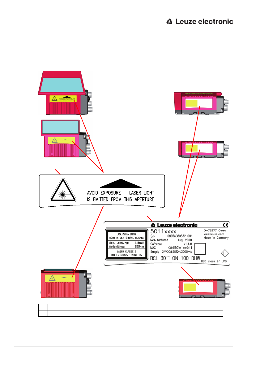
A Warning: laser aperture
B Name plate
BCL 348i
with deflection mirror and
M12 MS 3xx connection hood
The use of optical instruments or devices in combination with the device increases
the danger of eye damage!
The housing of the BCL 348i is provided with warning notices A and B above and next
to the reading window as shown in the following figure:
Figure 2.1: Attachment of the stick-on labels with warning notices at the BCL 348
12 BCL 348i Leuze electronic
i
Page 17

Fast commissioning / operating principle
3 Fast commissioning / operating principle
Below you will find a short description for the initial commissioning of the BCL 348i. Detailed
explanations for all listed points can be found throughout this technical description.
3.1 Mounting the BCL 348i
The BCL 348i bar code readers can be mounted in two different ways:
• Via four M4x6 screws on the bottom of the device.
• Via a BT 56 mounting device in the fastening groove on the bottom of the housing.
3.2 Device arrangement and selection of the mounting location
In order to select the right mounting location, several factors must be considered:
• Size, orientation, and position tolerance of the bar codes on the objects to be
scanned.
• The reading field of the BCL 348i in relation to the bar code module width.
• The resulting minimum and maximum reading distance from the respective reading
field.
• The permissible cable lengths between the BCL 348i and the host system depending
on which interface is used.
• The correct time for data output. The BCL 348i should be positioned in such a way
that, taking into consideration the time required for data processing and the conveyor
belt speed, there is sufficient time to e.g. initiate sorting operations on the basis of the
read data.
• The display and control panel should be very visible and accessible.
• For configuring and commissioning with the webConfig tool, the USB interface should
be easily accessible.
For specific information, please refer to chapter 6 and chapter 7.
Notice!
The beam exits the BCL 348i as follows for the respective devices:
- line scanner parallel to the housing base
- deflection mirror 105 degrees to the housing base
- oscillating mirror perpendicular to the housing base.
The black areas in figure 6.2 are the housing base. The best read results are obtained when:
• The BCL 348i is mounted in such a way that the scanning beam is incident on the bar
code at an angle of inclination greater than ±10° … 15° to vertical.
• The reading distance lies in the middle area of the reading field.
• The bar code labels are of good print quality and have good contrast ratios.
• You do not use high-gloss labels.
• There is no direct sunlight.
Leuze electronic BCL 348i 15
TNT 35/7-24V
Page 18
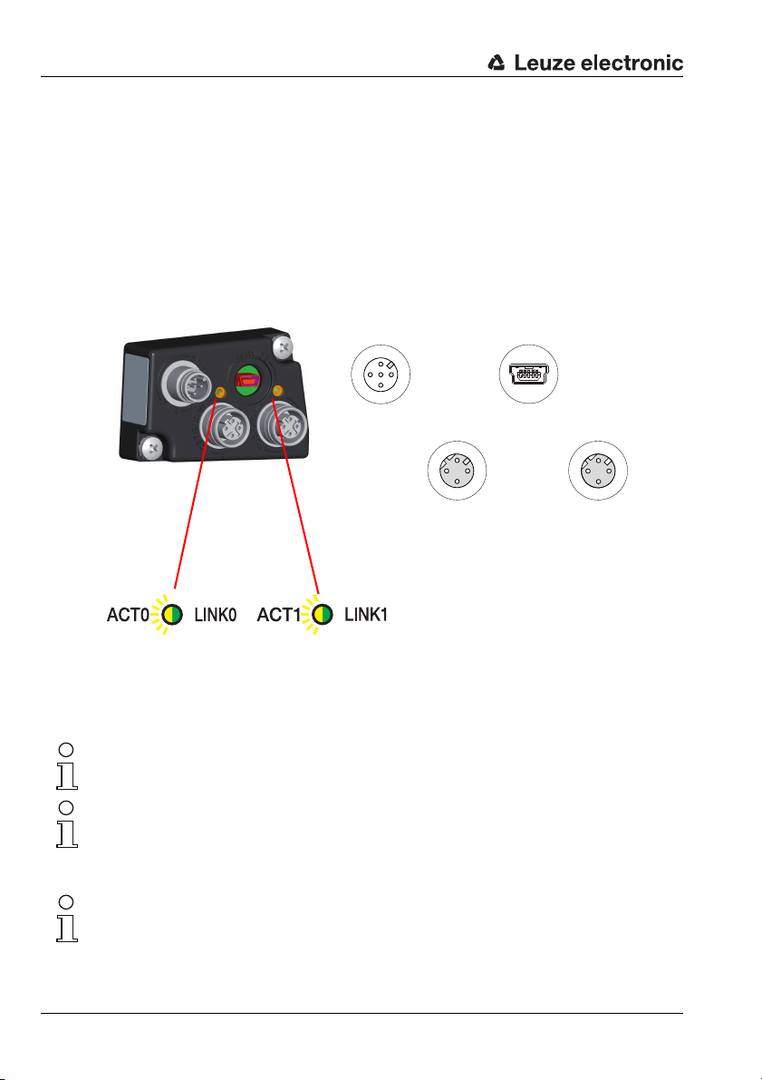
Fast commissioning / operating principle
PWR / SW IN/OUT
SWIO_2
SWIO_1
3
2
1
4
5
GNDIN VIN
FE
SERVICE
21354
GNDD+D-VB ID
BUS OUTHOST / BUS IN
TD+
1
2
3
4
RD+
RD-
TD-
TD+
1
2
3
4
RD+
RD-
TD-
Mini-B USB socket
(behind protective cap)
M12 plug
(A-coded)
M12 socket
(D-coded)
Ethernet 0
M12 socket
(D-coded)
Ethernet 1
Hood with integrated connectors
MS 348
Ethernet 1 LED
(split, two-colored):
ACT1 / LINK1
Ethernet 0 LED
(split, two-colored):
ACT0 / LINK0
3.3 Electrical connectionBCL 348i
For the electrical connection of the BCL 348i, 2 connection variants are available.
The voltage supply (18 … 30V DC) is connected acc. to the connection type selected.
2 freely programmable switching inputs/outputs for individual adaptation to the respective application are also available here. Detailed information on this topic can be found in
chapter 7.4.1 and chapter 7.4.3.
MS 348 hood with 2 integrated M12 connectors
Figure 3.1: BCL 348i - MS 348 hood with integrated M12 connectors
Notice!
The shielding connection is done via the M12 connector housing.
Notice!
The integrated parameter memory for the simple replacement of the BCL 348i is located in
the MS 348. In the integrated parameter memory, both the settings and the PROFINET
name are saved and transmitted to a new device.
16 BCL 348i Leuze electronic
Notice!
In the case of PROFINET line topology, the network is interrupted when the BCL 348i is
removed from the MS 348.
Page 19
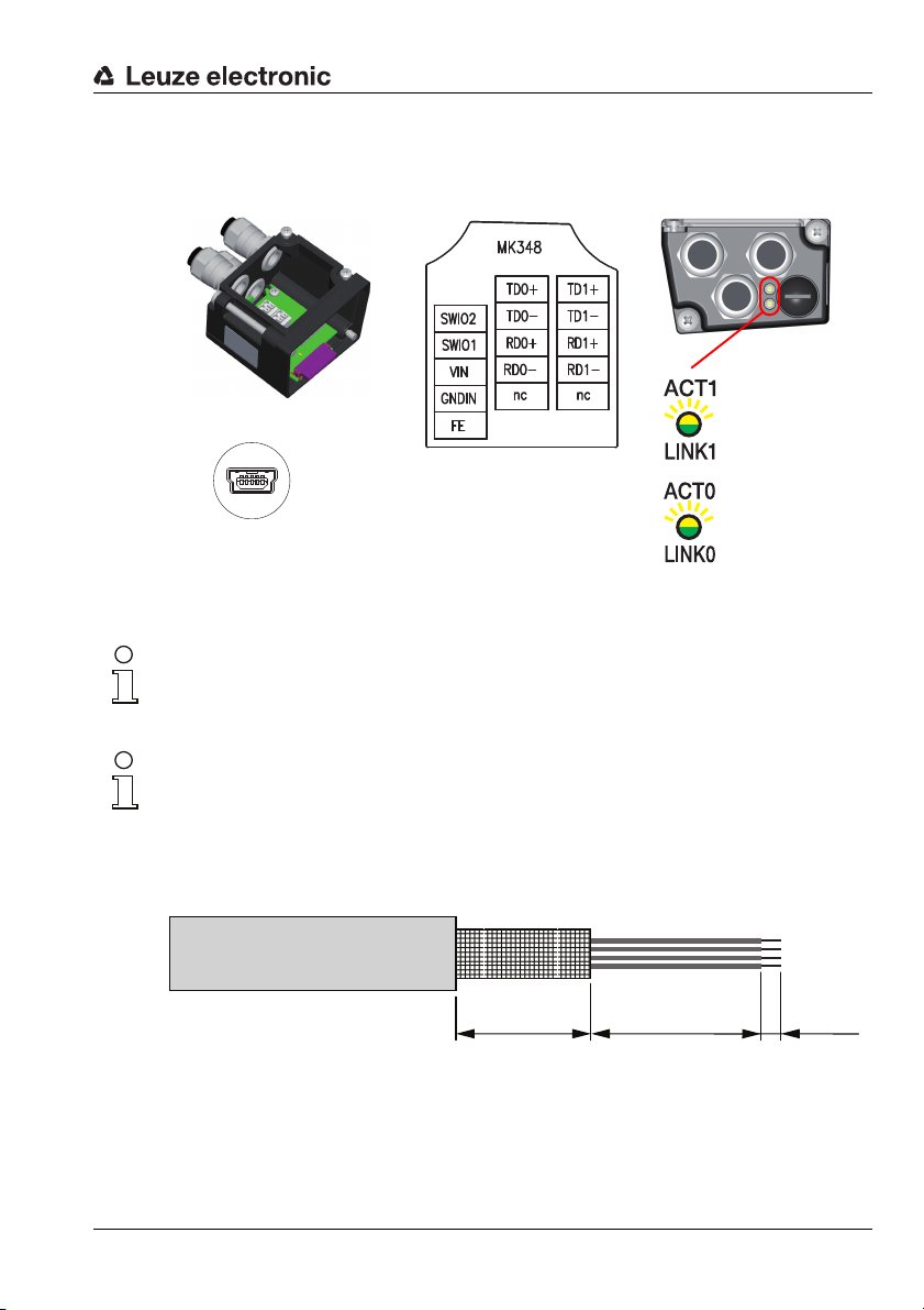
Terminal hood
MK 348
SERVICE
21354
GNDD+D-VB ID
Mini-B USB socket
(behind protective cap)
Terminal block
PWR / SW IN/OUT
Terminal block
HOST / BUS IN
(Ethernet 0)
Terminal designation
MK 348
Terminal block
BUS OUT
(Ethernet 1)
Ethernet 1 LED
(split, two-colored):
ACT1 / LINK1
Ethernet 0 LED
(split, two-colored):
ACT0 / LINK0
LEDs
MK 348
Fast commissioning / operating principle
MK 348 terminal hood with spring-loaded terminals
Figure 3.2: BCL 348i - MK 348 terminal hood with spring-loaded terminals
Notice!
The integrated parameter memory for simple exchange of the BCL 348i is located in the
MK 348. In the integrated parameter memory, both the settings and the PROFINET name
are saved and transmitted to a new device.
Notice!
In the case of PROFINET line topology, the network is interrupted when the BCL 348i is
removed from the MK 348.
Cable fabrication and shielding connection
Remove approx. 78mm of the connection cable sheathing. 15 mm of sheath of the shielded
line must be freely accessible.
TNT 35/7-24V
Leuze electronic BCL 348i 17
≈ 55 mm ≈ 8 mm ≈ 15 mm
Figure 3.3: Cable fabrication for MK 308 terminal hood
The shield is automatically contacted when the cable is lead into the metal screw fitting and
fastened when the cord grip is closed. Then lead the individual wires into the terminals
according to the diagram. Wire end sleeves are not necessary.
Page 20

Fast commissioning / operating principle
3.4 Preparatory PROFINET-IO settings
Connect the supply voltage +18 … 30VDC (typ. +24VDC); the BCL 348i starts up and
the bar code reading window appears on the display:
First, you need to assign its individual device name to the BCL 348i. The PLC must communicate this device name to the participant during the "device naming". Further information
may be found below and in chapter "Step 5 – Configuration of the device name - naming the
device" on page 103.
3.4.1 Commissioning the BCL 348i on the PROFINET-IO
Complete the necessary steps for commissioning a Siemens-S7 control as described
below.
Further information regarding the individual commissioning steps is provided in see chapter
10.4 "Configuration steps for a Siemens Simatic S7 control".
18 BCL 348i Leuze electronic
Page 21
3.4.2 Preparing the control system
In the first step, assign an IP address to the IO Controller (S7 PLC) and prepare the
control for a consistent data transmission.
Notice!
If an S7 control is used, you need to ensure that Simatic-Manager Version 5.4 + service
pack 5 (V5.4+SP5) or higher is used.
3.4.3 Installing the GSD file
For the subsequent configuration of the IO devices, e.g., BCL 348i, the corresponding GSD
file must be loaded first. All data in modules required for operating the BCL 348i is described
in this file. These are input and output data and device parameters for the functioning of the
BCL 348i and the definition of the control and status bits.
Install the GSD file associated with the BCL 348i in the PROFINET-IO Manager of your
control.
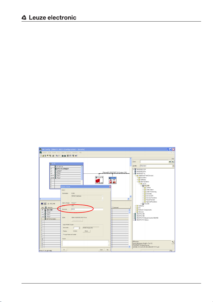
3.4.4 Configuration
Configure the PROFINET-IO system with the HW Config of the SIMATIC Manager by
inserting the BCL 348i into your project.
Fast commissioning / operating principle
Figure 3.4: Assignment of the device names to IP addresses
Here, an IP address is assigned to a unique "device name".
Leuze electronic BCL 348i 19
TNT 35/7-24V
Page 22

Fast commissioning / operating principle
3.4.5 Transfer of the configuration to the IO Controller
Transfer the PROFINET-IO configuration to the IO Controller (S7 PLC).
After the correct transfer to the IO Controller (S7 PLC), the PLC automatically carries
out the following activities:
• Check device names
• Assignment of the IP addresses that were configured in the HW Config to the
IO devices
• Establishment of a connection between the IO Controller and configured
IO devices
• Cyclical data exchange
Notice!
Participants that have not been "named" cannot be contacted yet at this point in time!
20 BCL 348i Leuze electronic
Page 23
Fast commissioning / operating principle
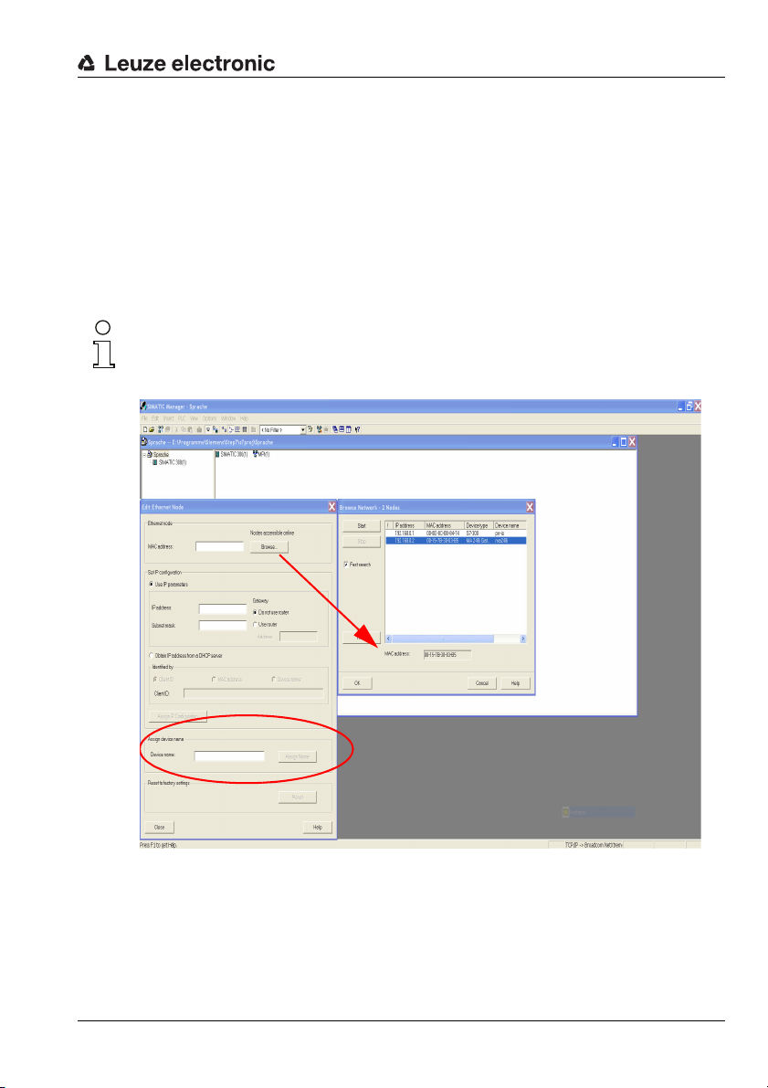
3.4.6 Configuration of the device name - device naming
PROFINET-IO defines the "naming of the device" as the creation of a name-based relationship for a PROFINET-IO device.
Assigning the device names to the configured IO devices
Select the respective bar code scanner BCL 348i for the "device naming" based on its
MAC address.
The unique "device name" (which must match the participant in the HW Config) is then
assigned to this participant.
Notice!
Multiple BCL 348i can be distinguished by the MAC addresses displayed. The MAC address
may be found on the name plate of the respective bar code scanner.
Figure 3.5: Assigning the device names to the configured IO devices
Leuze electronic BCL 348i 21
TNT 35/7-24V
Page 24
Fast commissioning / operating principle
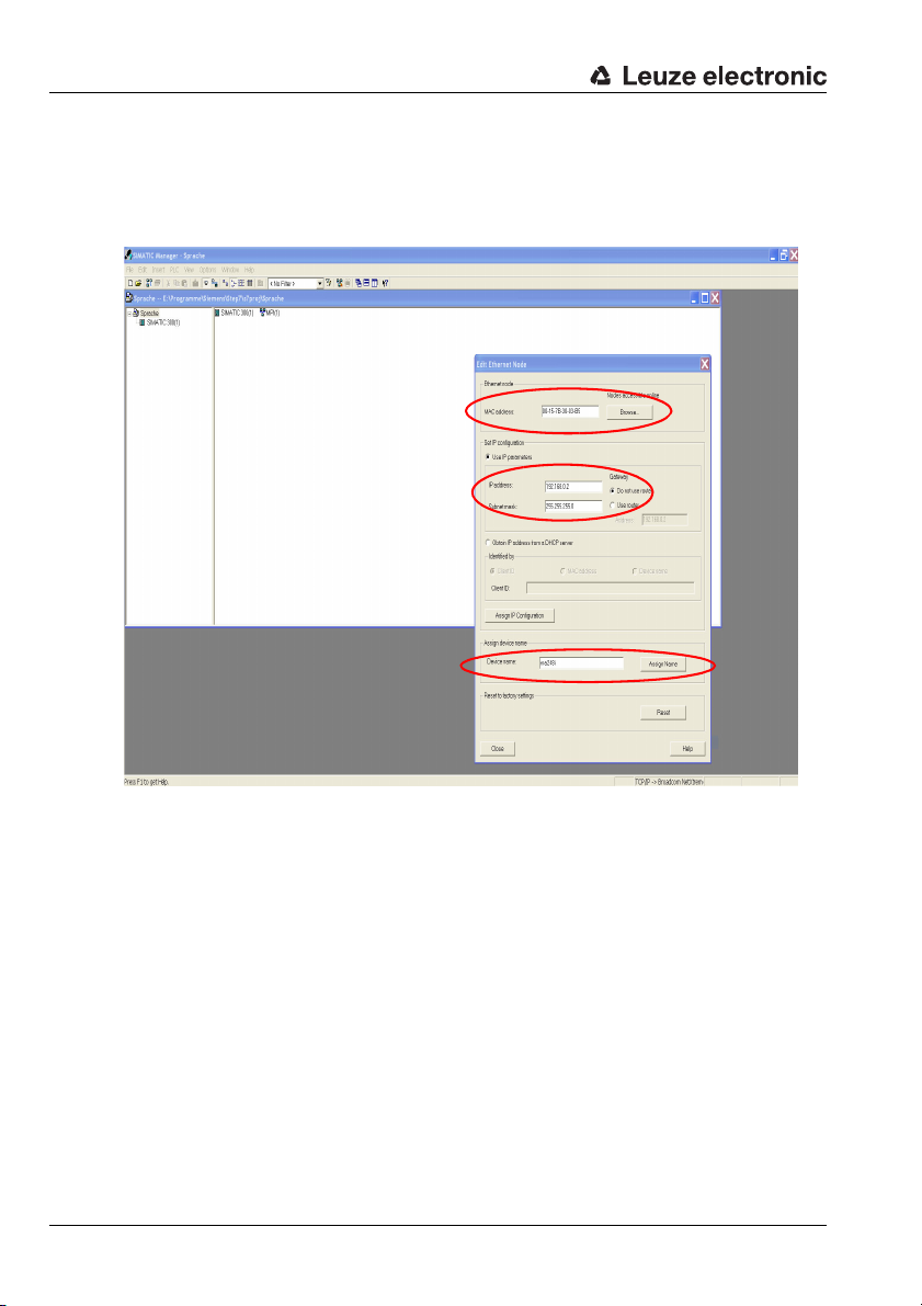
Assignment of MAC address - IP address -individual device name
At this point, assign an IP address (suggested by the PLC), a subnet mask and, if
required, a router address, and assign this data to the named participant ("device
name").
Figure 3.6: MAC address - IP address -individual device name
From now on, and when programming, only the unique "device name" (max. 255 characters)
is used.
3.4.7 Check device name
After completing the configuration phase, recheck the "device names" that have been
assigned. Please ensure that these names are unique and that all participants are located in the same subnet.
3.5 Further settings
Carry out further settings via the PROFINET-IO Controller, such as the control of the
decoding and processing of the read data and the configuration of the connected switching
inputs and outputs, using the parameters provided by the GSD file.
Activate the desired modules (at least module 10 and one of the modules 21 … 27).
22 BCL 348i Leuze electronic
Page 25
3.6 Starting the device
Connect the +18 … 30VDC supply voltage (typ. +24VDC).
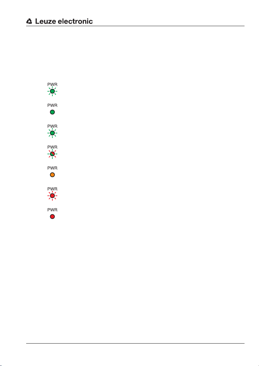
The BCL 348i starts up, the PWR and BUS LEDs display the operating state. If there is a
display, the bar code reading window appears in it.
PWR LED
flashes green Device ok, initialization phase
green continuous light Power On, device OK
green, briefly off - on Good read, successful reading
green, briefly off - briefly red - on No read, reading not successful
yellow continuous light Service mode
flashes red Warning set
Fast commissioning / operating principle
red continuous light Error, device error
Leuze electronic BCL 348i 23
TNT 35/7-24V
Page 26
Fast commissioning / operating principle
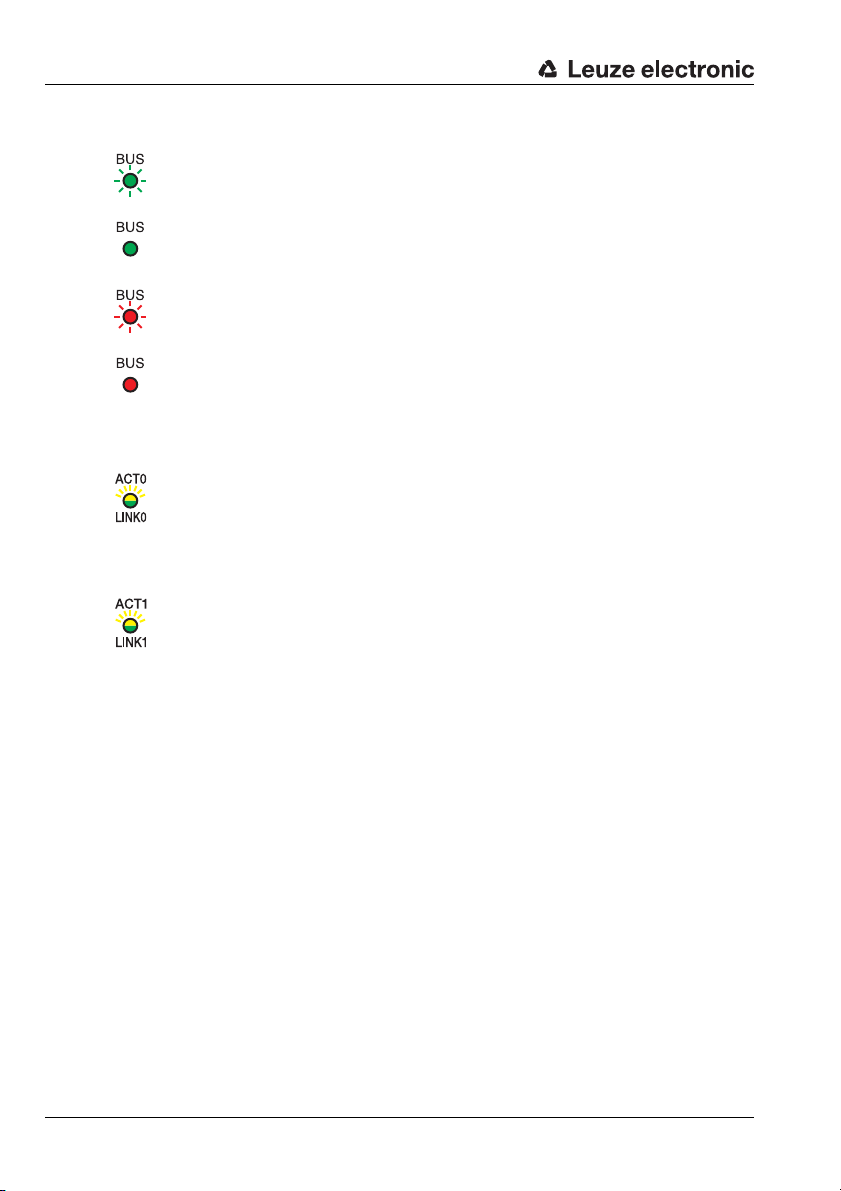
BUS LED
flashes green Initialization
green continuous light Network operation OK
flashes red Communication error
red continuous light Network error
LED ACT0 / LINK0 (on the MS 308/MK308)
green continuous light Ethernet connected (LINK)
yellow flickering light Data communication (ACT)
LED ACT1 / LINK1 (on the MS 308/MK308)
green continuous light Ethernet connected (LINK)
yellow flickering light Data communication (ACT)
If a display is available, the following information appears successively during startup:
• Startup
• Device designation e.g. BCL 348i SM 102 D
• Reading Result
If Reading Result is displayed, the device is ready.
Operation of BCL 348i
After voltage (18 … 30V DC) has been connected to the switching input, a read process is
activated. In the standard setting, all common code types for decoding are released; only
the 2/5 Interleaved code type is limited to 10 digits of code content.
If a code is moved through the reading field, the code content is decoded and forwarded to
the superior system (PLC/PC) via the PROFINET-IO.
24 BCL 348i Leuze electronic
Page 27

3.7 Bar code reading
Modul 0,5
6677889900
To test, you can use the following bar code in the 2/5 Interleaved format. The bar code
module here is 0.5:
Provided your BCL 348i model has a display, the read information appears on this display.
The PWR LED goes off briefly and then turns green again. Simultaneously, the read information is forwarded to the superior system (PLC/PC) via the PROFINET-IO.
Please check the incoming data of the bar code information there.
Alternatively, you can use a switching input for read activation (switching signal of a photoelectric sensor or 24VDC switching signal).
Fast commissioning / operating principle
Leuze electronic BCL 348i 25
TNT 35/7-24V
Page 28
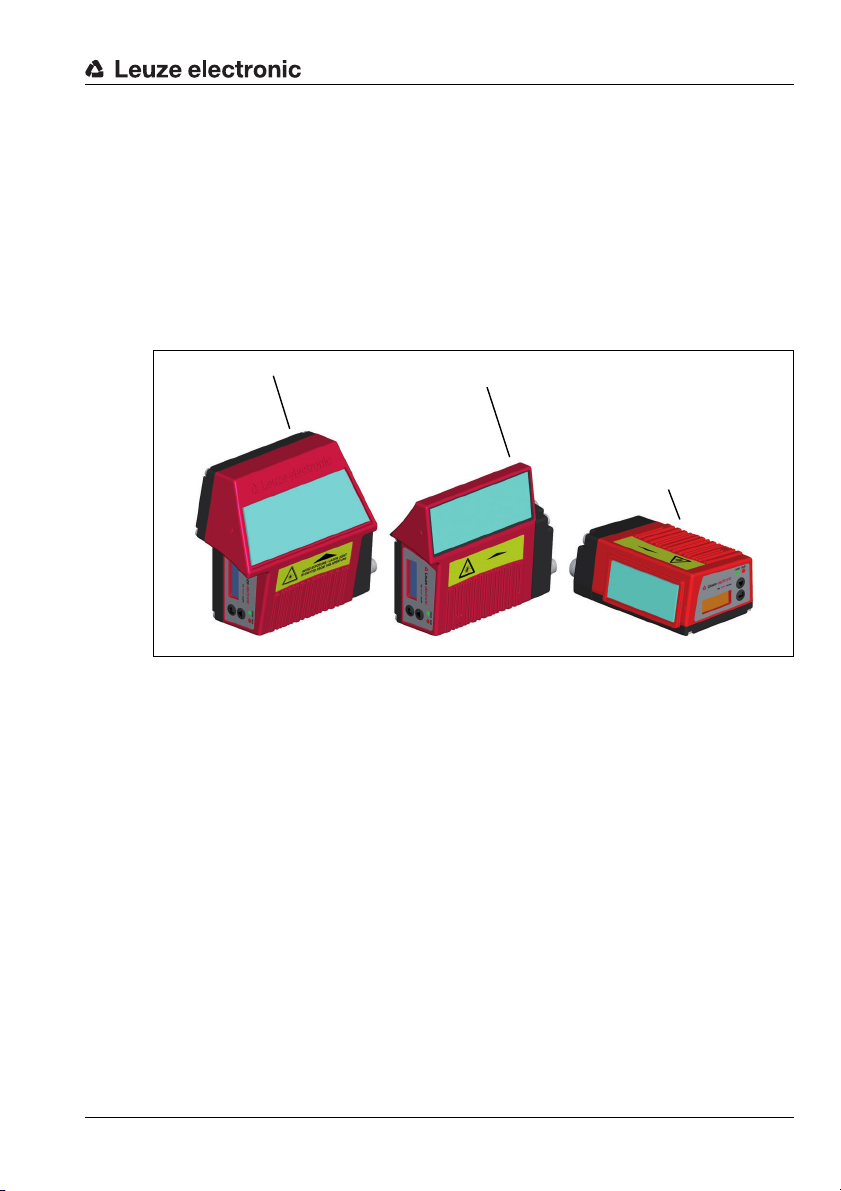
4 Device description
Line scanner
Line scanner with deflection mirror
Oscillating-mirror scanner
4.1 About the bar code readers of the BCL 300i series
Bar code readers of the BCL 300i series are high-speed scanners with integrated decoder
for all commonly used bar codes, e.g. 2/5 Interleaved, Code 39, Code 128, EAN 8/13 etc.,
as well as codes from the GS1DataBar family.
Bar code readers of the BCL 300i series are available in various optics models as well as
line scanner
heated models.
s, line scanners with deflection mirrors, oscillating mirrors and also optionally as
Device description
Figure 4.1: Line scanner, line scanner with deflection mirror and oscillating-mirror scanner
The extensive options for device configuration enable adaptation to a multitude of reading
tasks. Due to the large reading distance combined with the great depth of field, a large
opening a
and storage technology market.
The interfaces (RS 232, RS 485 and RS 422) integrated in the various device models and
the fieldbus systems (PROFIBUS DP, PROFINET-IO and Ethernet) offer optimum connec-
tion to the superior host system.
Leuze electronic BCL 348i 25
ngle and a very compact construction, the device is ideally suited for the conveyor
TNT 35/7-24V
Page 29
Device description
4.2 Characteristics of the bar code readers of the BCL 300i series
Performance characteristics:
•Integrated fieldbus connectivity = i -> Plug-and-Play fieldbus coupling and easy
networking
•Numerous interface variants facilitate connection to the superior systems
•RS 232, RS 422
•RS 485 and multiNet plus slave
alternatively, various fieldbus systems, such as
•PROFIBUS
•PROFINET-IO
•EtherNet
•Integrated code fragment technology (CRT) enables the identification of soiled or
damaged bar codes
•Maximum depth of field and reading distances from 30mm to 700 mm
•Large optical opening angle and, thus, large reading field width
• High scanning rate of 1000 scans/s for fast reading tasks
•On request with display to easily detect and activate functions
•Integrated USB service interface, Mini-B type
•Adjustment of all device parameters with a web browser
•Easy alignment- and diagnostics functions
• Up to four possible connection technologies
• Two freely programmable switching inputs/outputs for the activation or signaling of
states
•Automatic monitoring of the read q
•Automatic recognition and setting of the bar code type using autoConfig
• Reference code comparison
•Optional heating models to -35°C
•Heavy-duty housing of protection class IP 65
DP
and status messages.
uality with autoControl
Notice!
Information on technical data and characteristics can be found in Kapitel 5.
General information
The integrated fieldbus connectivity = i contained in the bar code readers of the BCL 300i
series facilitates the use of identification systems which function without connector unit or
gateways. The integrated fieldbus interface considerably simplifies handling. The Plug-andPlay concept enables easy networking and very simple commissioning: Directly connect the
respective fieldbus and all configuration is performed with no
For decoding bar codes, the bar code readers of the BCL 300i series make available the
proven CRT decoder with code fragment technology:
The proven code fragment technology (CRT) enables bar code readers of the BCL 300i
series to read bar codes with a small bar height, as well as bar codes with a damaged or
soiled print image.
26 BCL 348i Leuze electronic
additional software.
Page 30
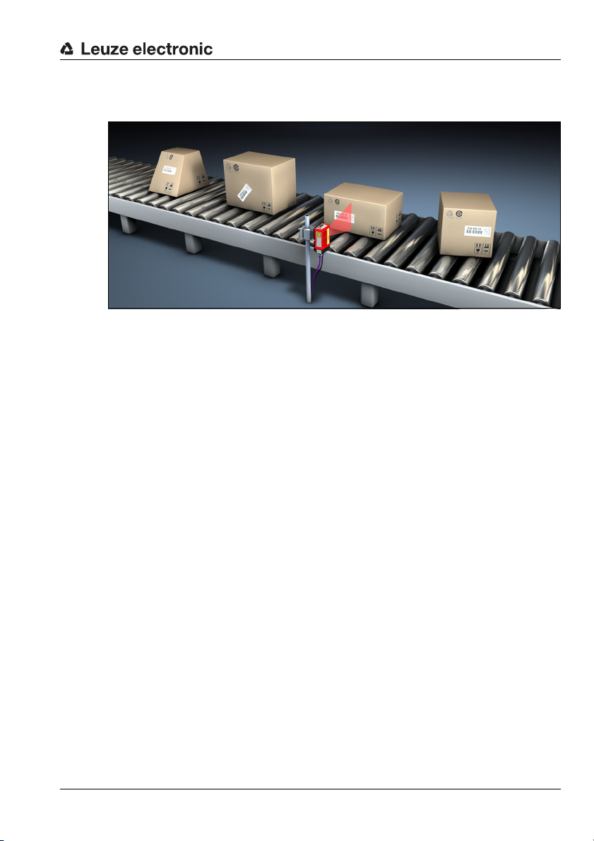
Device description
With the aid of the CRT decoder, bar codes can also be read without problem in other
demanding situations, such as with a large tilt angle (azimuth angle or even twist angle).
Figure 4.2: Possible bar code orientation
With the BCL 348i, configuration is generally performed with the aid of the GSD file.
The BCL 348i needs a suitable activation to st
the reading field. This opens a time window ("reading gate") in the BCL 348i for the read
process during which the bar code reader has time to detect and decode a bar code.
Alternative activation options include online commands via the host interface and the In the
basic setting, triggering takes place through an external reading cycle signa
PROFINET-IO. An alternative option for activation is the autoReflAct function.
Through the read operation, the BCL 348i collects additional useful pieces of data for diagnosis which can also be transmitted to the host. The quality of the read operation can be
inspected using the alignment mode which is integrated in the webConfig tool.
An optional display in English with
visualization purposes. Two LEDs provide additional optical information on the current operating state of the device.
The two freely configurable switching inputs/outputs SWIO1 and SWIO2 can be assigned
various functions and control e.g. activation of the BCL 348i or external device
PLC.
System, warning and error messages provide assistance in setup/troubleshooting during
commissioning and read operation.
buttons is used to operate the BCL 348i as well as for
art a read process as soon as an object is in
l or via the
s, such as a
TNT 35/7-24V
Leuze electronic BCL 348i 27
Page 31

Device description
Connection side for:
MK 3xx terminal hood
MS3xx hood with
integrated connectors
Reading window
Dovetail mounting
and 4 mounting
threads
Display, LEDs
and buttons
Line scanner
Connection side for:
MK 3xx terminal hood
MS3xx hood with
integrated connectors
Reading window
Dovetail mounting
and 4 mounting
threads
Display, LEDs
and buttons
Line scanner with deflection mirror
4.3 Device construction
BCL 348i bar code readers
Figure 4.3:BCL348i device construction - line scanner
Figure 4.4: BCL 348i device construction -line scanner with deflection mirror
28 BCL 348i Leuze electronic
Page 32

Device description
Connection side for:
MK 3xx terminal hood
MS3xx hood with
integrated connectors
Reading window
Dovetail mounting
and 6 mounting
threads
Display, LEDs
and buttons
Oscillating-mirror scanner
Figure 4.5: BCL 348i device construction - oscillating-mirror scanner
Leuze electronic BCL 348i 29
TNT 35/7-24V
Page 33

Device description
Connection side with
system plug for
connection to
BCL 348i
M12 connector,
3 x M12
Mini-B type USB
service interface
Ethernet LEDs
LINK / ACT
Connection side with
system plug for
connection to
BCL 348i
Cable lead-throughs
Mini-B type USB
service interface
Terminal compartment
Ethernet LEDs
LINK / ACT
MS 348 hood with integrated connectors
Figure 4.6: Device construction MS348 hood with integrated connectors
MK 348 terminal hood
30BCL348i Leuze electronic
Figure 4.7: Device construction MK 348 hood with integrated connectors
Page 34

4.4 Reading techniques
4.4.1 Line scanner (single line)
A line (scan line) scans the label. Due to the opt. opening angle, the reading field width is
dependent on the read distance. Through the movement of the object, the entire bar code
is automatically transported through the scan line.
The integrated code fragment technology permits twisting of the bar code (tilt angle) within
certain limits. These are dependent on the transport speed, the scanning rate of the scanner
and the bar code properties.
Areas of application of the line scanner
The line scanner is used:
• when the bars of the bar code are printed in the conveying direction ('ladder
arrangement').
•with bar codes having very short bar lengths.
• when the ladder code is turned out of the vertical position (tilt angle).
• when the reading distance is large.
Device description
Figure 4.8: Deflection principle for the line scanner
Leuze electronic BCL 348i 31
TNT 35/7-24V
Page 35

Device description
4.4.2 Line scanner with oscillating mirror
The oscillating mirror deflects the scan line additionally to both sides across the scan direction at a randomly adjustable oscillation frequency. In this way, the BCL 348i can also scan
larger areas or spaces for bar codes. The reading field height (and the scan line length
useful for evaluation) depends
the oscillating mirror.
Areas of application of the line scanner with oscillating mirror
For line scanners with oscillating mirror, oscillation frequency, start/stop position etc. are
adjustable. It is used:
• when the position of the label is not fixed, e.g. on pallets – various labels can, thus, be
detected at various positions.
• when the bars of the bar code are printed perpendicular to the conveying direction
('picket fence arrangement').
• when reading stationary ob
• when a large reading field (reading window) has to be covered.
on the reading distance due to the optical opening angle of
jects.
Figure 4.9: Deflection principle for the line scanner with oscillating mirror add-on
32BCL348i Leuze electronic
Page 36

4.4.3 Raster scanner (Raster Line)
Multiple scan lines scan the label. Due to the optical opening angle, the reading field width
is dependent on the reading distance. Provided the code is located in the reading field, it can
be read during standstill. If the code moves through the reading field, it is scanned by
multiple scan lines.
The integrated code fragment technology permits twisting of the bar code (tilt angle) within
certain limits. These are dependent on the transport
and the bar code properties. In most cases, everywhere a line scanner is used, a raster
scanner can be used.
Areas of application of the raster scanner:
The raster scanner is used:
• when the bars of the bar code are perpendicular to the conveying direction ('picket
fence arrangement')
•with bar codes with low height displacement
• with very glossy bar codes
Device description
speed, the scanning rate of the scanner
Figure 4.10: Deflection principle for the raster scanner
Leuze electronic BCL 348i 33
TNT 35/7-24V
Page 37

Device description
4.5 Fieldbus systems
Various product variants of the BCL 300i series are available for connecting to different
fieldbus systems such as PROFIBUS DP, PROFINET-IO and Ethernet.
4.5.1 PROFINET-IO
The BCL 348i is designed as a PROFINET-IO device (acc. to IEEE 802.3). It supports a
transmission rate of up to 100 Mbit/s (100BaseTX/FX), full duplex, as well as auto-negotia-
tion and auto-crossover.
The functionality of the device is defined via parameter sets which are clustered in modules.
These modules are contained in a GSDML file.
Each BCL 348i is sealed with a unique MAC-ID. This information is used to assign a unique,
plant-specific device name ("NameOfStation") to the device via the "Discovery and Configuration Protocol (DCP)". When configuring a PROFINET-IO system, the assignment of the
device names to the configured IO devices creates a name-based relationship for the participating IO devices ("device naming"). F
– Einstellen des Gerätenamens - Gerätetaufe" auf Seite 103.
The BCL 348i features multiple M 12 connectors / sockets for the electrical connection of the
supply voltage, the interface and the switching inputs and outputs. Additional information on
the electrical connection can be found in Kapitel 7.
The BCL 348i supports:
urther information can be found in section "Schritt 5
•PROFIBU
systems
•Modular structure of the IO data
• PROFINET-IO RT (Real Time) communication
• Standard Fast Ethernet (100 Mbit/s) connections (M12 technology)
•Integrated Ethernet switch/ 2 Ethernet ports
• PROFINET-IO Conformance Class B (CC-B)
•I&M support: I&M0
For further details, see Kapitel 10!
34BCL348i Leuze electronic
S-IO device functionality based on the PROFIBUS profile for identification
Page 38

Device description
Identification & Maintenance Functions
The BCL 348i supports the base record I&M0:
Contents Index Data type Description Value
Header 0 10 bytes
MANUFACTURER_ID 10 UNSIGNED16
ORDER_ID 12 ASCII string 20 bytes Leuze order no.
SERIAL_NUMBER 32ASCII string 16 bytes Unique device serial number
HARDWARE_REVISION 48 UNSIGNED16
SOFTWARE_REVISION 50
REVISION_COUNTER 54 UNSIGNED16
PROFILE_ID 56 UNSIGNED16
PROFILE_SPECIFIC_TYPE 58 UNSIGNED16
IM_VERSION 60 2xUNSIGNED8
IM_SUPPORTED 62 Bit[16]
1xCHAR,
3xUNSIGNED8
Table 4.1: Base record I&M0
Manufacturer specific
Manufacturer specific
Leuze PNO manufacturer ID
Leuze manufacturer ID
Hardware revision number,
e.g., "0…6 5535"
Software version number,
e.g. V130 correspond to
"V1.3.0"
Is incremented when updating individual modules. This
function is not supported.
PROFIBUS application profile number
Info about subchannels and
submodules. Not relevant
Implemented I&M version V
1.1
Optional I&M records avail-
able
338
Devicedependent
Devicedependent
Devicedependent
0
0x0000
(Non Profile)
0x0003
(I/O Module)
0x01,0x01
0
The BCL 348i supports further protocols and services for communication:
• TCP / IP (Client / Server)
•UDP
•DCP
•ARP
•PING
Further information on commissioning can be found in Kapitel 10.
Leuze electronic BCL 348i 35
TNT 35/7-24V
Page 39

Device description
PC / PLC host interface
Other network participants
BCL 348i with
MS348 hood with inte-
grated connectors
BCL 348i with
MK348 terminal hood
myBCL 348i_2
4.5.2 PROFINET-IO – star topology
The BCL 348i can be operated as a single device (standalone) with an individual device
name in a star topology. The PLC must communicate this device name to the participant
during the "device naming".
Figure 4.11: PROFINET-IO in a star topology
36BCL348i Leuze electronic
Page 40

4.5.3 PROFINET-IO – linear topology
PC / PLC host interface
BCL 348i
myBCL 348i_1
to other network participants
BCL 348i
myBCL 348i_2
BCL 348i
myBCL 348i_3
The innovative further development of the BCL 348i with integrated switch functionality
offers the option of connecting multiple bar code readers of type BCL 348i to one another
without direct connection to a switch. In addition to the classic "star topology", a "linear
topology" is thus also possible.
Figure 4.12: PROFINET-IO in a linear topology
Each participant in this network requires its own unique device name that is ass
PLC during the "device naming". For specific information, please refer to s ection "Schritt 5
– Einstellen des Gerätenamens - Gerätetaufe" auf Seite 103.
The maximum length of a segment (connection from the hub to the last participant) is limited
to 100m.
Device description
igned by the
4.6 Heater
4.7 External parameter memory in the MS 348 / MK 348
Leuze electronic BCL 348i 37
For low-temperature applications to min. -35°C (e.g. in cold storage), the bar code readers
of the BCL 348i series can optionally be permanently fitted with a built-in heating and these
bar code readers purchased as separate device models.
The parameter memory available in the MS348 or MK 348 simplifies the time saving on-site
exchange of a BCL 348i by providing a copy of the current parameter set of the BCL 348i
and by storing the device name as well. This eliminates the need to configure the exchanged
device manually and, in particular, a new naming of the device – the control can immediately
access the exchanged BCL 3
48i.
TNT 35/7-24V
Page 41

Device description
4.8 autoReflAct
AutoReflAct stands for Automatic Reflector Activation and permits an activation without
additional sensors. This is achieved by directing the scanner with reduced scanning beam
towards a reflector mounted behind the conveyor path.
Notice!
Compatible reflectors are available on request.
As long as the scanner is targeted at the reflector, the reading gate remains clos
however, the reflector is blocked by an object such as a container with a bar code label, the
scanner activates the read procedure, and the label on the container is read. When the path
from the scanner to the reflector has cleared, the read procedure has completed and the
scanning beam is reduced and again directed onto the reflector. The reading gate is closed.
Figure 4.13: Reflector a
The autoReflAct function uses the scanning beam to simulate a photoelectric sensor and
thus permits an activation without additional sensor system.
4.9 Reference codes
The BCL 348i offers the possibility of storing one or two reference codes.
It is possible to store the reference codes via the webConfig tool, via online commands or
PROFINET-IO.
The BCL 348i can compare read bar codes with one and/or both reference codes and
execute user-configurable functions depending on the comparison result.
ed. If,
rrangement for autoReflAct
38 BCL 348i Leuze electronic
Page 42

4.10 autoConfig
With the autoConfig function, the BCL 348i offers the user who only wishes to simultaneously read one code type (symbology) with one number of digits an extremely simple and
convenient configuration option.
After starting the autoConfig function via the switching input or from a superior control, it is
sufficient to position a bar code label with the desired code type and number of digits in the
reading field of the BCL 348i.
Afterward,
decoded.
Notice!
The settings made via the webConfig configuration tool push the parameters set in the
PROFINET-IO only temporarily into the background. They are overwritten during integration
into the PROFINET-IO or after deactivation of service mode of the PROFINET master with
those settings made via the GSD file!
Device settings for operating the BCL 348i on the PROFINET-IO are managed and
configured exclusively by the PROFINET-IO Controller (PLC). Permanent changes
must be carried out here!
Detailed information on this topic can be found in Kapitel 10 "Inbetriebnahme und Konfigu-
ration" auf Seite 97.
bar codes with the same code type and number of digits are recognized and
Device description
Leuze electronic BCL 348i 39
TNT 35/7-24V
Page 43

5 Specifications
5.1 General specifications of the bar code readers
5.1.1 Line scanner / raster scanner
Specifications
Type BCL 348i
PROFINET-IO
Type Line scanner without heating
Optical data
Light source Laser diode λ = 655nm (red light)
Beam exit Front
Scanning rate 1000 scans/s
Beam deflection by means of rotating polygon wheel
Useful opening angle max. 60°
Optics models / resolution High Density (N): 0.127 … 0.20 mm
Reading distance see reading field curves
Laser class 2 (acc. to EN 60825-1 and 21 CFR 1040.10 with Laser Notice No. 50)
Medium Density (M): 0.20 … 0.5mm
Low Density (F): 0.30…0.5mm
Ultra Low Density (L): 0.35…0.8 mm
Bar code data
Code types 2/5 Interleaved, Code 39, Code 128, EAN 128, EAN / UPC,
Bar code contrast (PCS) >= 60%
External light tolerance 2000 lx (on the bar code)
Number of bar codes per scan 3
Codabar, Code 93, GS1 DataBar, EAN Addendum
Electrical data
Interface type 2x PROFINET-IO
Protocols PROFINET-IO RT-communication
Baud rate 10/100MBaud
Data formats
Service interface Mini-B type USB 2.0 socket
Switching input /
switching output
Operating voltage 18 … 30VDC (Class 2, safety class III)
Power consumption max. 3.7W
- Switching output: 18 … 30 VDC, depending on supply voltage, I ma
2 switching inputs/outputs, freely programmable functions
- Switching input: 18 … 30 V DC depending on supply voltage, I max. = 8mA
Switching inputs/outputs protected against polarity reversal!
on 2x M12 (D)
DCP
TCP/IP (Client/ Server) / UDP
x. = 60mA
(short-circuit proof)
Operating and display elements
Display monochromatic graphical display, 1 2 8 x 32 pixel, with background lighting
Keyboard 2 buttons
LEDs 2 LEDs for power (PWR) and bus state (BUS), two-colored (red/green)
TNT 35/7-24V
Leuze electronic BCL 348i 41
Page 44

Specifications
Type BCL 348i
PROFINET-IO
Type Line scanner without heating
Mechanical data
Protection class
Weight
Dimensions (WxHxD)
Housing
270g (without connection hood)
44 x 95x68mm (without connection hood)
diecast aluminum
IP 65
1)
Environmental data
Operating temperature range 0°C … +40 °C
Storage temperature range -20°C … +70°C
Air humidity max. 90% rel. humidity, non-condensing
Vibration IEC 60068-2-6, test FC
Shock IEC 60068-2-27, test Ea
Continuous shock IEC 60068-2-29, test Eb
Electromagnetic compatibility EN 55022;
1) Only with the MS348 or MS348 connection hood and screwed-on M12 connectors or cable lead-
throughs and mounted caps. Minimum tightening torque of the housing connection screws on the connection hood 1.4Nm!
2) This is a Class A product. In a domestic environment this product may cause radio interference, in
which case the operator may be required to take adequate measures.
IEC 61000-6-2 (contains IEC 61000-4-2, -3, -4, -5 and -6)
Attention!
For UL applications, use is permitted exclusively in Class 2 circuits according to NEC
(National Electric Code).
The BCL 348i bar code readers are designed in accordance with safety class III for supply
by PELV (protective extra-low voltage).
2)
42 BCL 348i Leuze electronic
Page 45

5.1.2 Oscillating-mirror scanner
Technical data same as for line scanner without heating with the following differences:
Specifications
Type BCL 348i
PROFINET-IO
Type Oscillating-mirror scanner without heating
Optical data
Beam exit Lateral zero position at an angle of 90°
Beam deflection Via rotating polygon wheel (horizontal) and stepping motor with mirror (vertical)
Oscillation frequency 0 … 10Hz
Max. swivel angle ±20°(adjustable)
Reading field height see reading field curves
(adjustable, max. frequency is dependent on set swivel angle)
Electrical data
Power consumption max. 4.9W
Mechanical data
Weight 580g (without connection hood)
Dimensions (WxHxD)
58 x 125 x 110 mm (without connection hood)
Table 5.1: Specifications of the BCL 348i oscillating-mirror scanners without heating
5.1.3 Line scanner / raster scanner with deflection mirror
Technical data same as for line scanner without heating with the following differences:
Type BCL 348i
Type Line scanner with deflection mirror without heating
Optical data
Beam exit Lateral zero position at an angle of 90°
Beam deflection Via rotating polygon wheel (horizontal) and deflection mirror (vertical)
Max. optical adjustment range of
the beam exit
±10° (adjustable via display or software)
Electrical data
Power consumption max. 3.7W
Mechanical data
Weight 350g (without connection hood)
Dimensions (WxHxD)
44 x 103 x 96 mm (without connection hood)
Table 5.2: Specifications of the BCL 348i deflection-mirror scanners without heating
PROFINET-IO
TNT 35/7-24V
Leuze electronic BCL 348i 43
Page 46

Specifications
5.2 Heating models of the bar code readers
The BCL 348i bar code readers are optionally available as models with integrated heating.
In this case, heating is permanently installed ex works. Self-installation on-site by the user
is not possible!
Features
•Integrated heating (permanently installed)
• Extends the application range of the BCL 348i to -35°C
• Supply voltage 24VDC ±20%
•BCL348i enabling through an internal temperature switch
(switch-on delay about 30min for 24VDC and minimum ambient temperature
of -35°C)
•Necessary conductor cross-section for the voltage supply: at least 0.75mm²; the use
of ready-ma
Construction
The heating consists of two parts:
• The front cover heater
• The housing heater
Function
When the 24VDC supply voltage is applied to the BCL 348i, a temperature switch initially
only connects the heating to current (front cover heater and housing heater). During the
heating phase (around 30min), when the inside temperature rises above 15°C, the temper-
ature switch connects the BCL 348i to the supply voltage. This is followed by the self test
and the changeover to read operation. The "PWR" LED light
for operation.
When the inside temperature reaches approximately 18 °C, another temperature switch
turns the housing heater off and, if necessary, back on again (if the inside temperature drops
below 15°C). This does not interrupt the read operation. The front cover heater remains activated until an inside temperature of 25 °C is rea
cover heater switches off and, with a switching hysteresis of 3°C, back on again at an inside
temperature below 22°C.
de cables is, thus, not possible
ched. At temperatures above this, the front
s up, showing overall readiness
Mounting location
Notice!
The mounting location is to be selected such that it does not expose the BCL 348i with heating directly to a cold air stream. To achieve an optimal heating effect, the BCL 348i should
be mounted so that it is thermally isolated.
Electrical connection
The required core cross section of the connection cable for the voltage supply must be at
least 0.75 mm².
44 BCL 348i Leuze electronic
Page 47

Attention!
The voltage supply must not be looped through from one device to the next.
Power consumption
The energy requirement depends on the model:
• the line/raster scanner with heating typically consumes a maximum of 17W power.
• the line scanner with oscillating mirror and heating typically consumes a maximum of
26W power.
• the line/raster scanner with deflection mirror and heating typically consumes a
maximum of 19W power.
These values are based on operation with unconnected switching output
5.2.1 Line scanner / raster scanner with heater
Technical data same as for line scanner without heating with the following differences:
Specifications
s.
Type BCL 348i
PROFINET-IO
Type Line scanner with heater
Electrical data
Operating voltage 24 V DC ±20 %
Power consumption max. 17.7W
Structure of the heating Housing heating and separate heating of the optics glass
Warmup time Min. 30min at +24V DC and an ambient temperature of -35° C
Min. conductor cross section Conductor cross section of at least 0.75 mm² for the supply voltage supply line.
Wiring through of the voltage supply to multiple heating devices is
Standard, M12 ready-made cable not usable
(insufficient conductor cross section)
not
permissible.
Environmental data
Operating temperature range -35°C … +40°C
Storage temperature range -20°C … +70 °C
Table 5.3: Specifications of the BCL 348i line/raster scanners with heating
5.2.2 Oscillating-mirror scanner with heating
Technical data same as for line scanner without heating with the following differences:
Type BCL 348i
Type Oscillating-mirror scanner with heating
Optical data
Useful opening angle max. 60°
Max. swivel angle ± 20°(adjustable)
Table 5.4: Specifications of the BCL 348i oscillating-mirror scanners with heating
PROFINET-IO
TNT 35/7-24V
Leuze electronic BCL 348i 45
Page 48

Specifications
Type BCL 348i
PROFINET-IO
Type Oscillating-mirror scanner with heating
Electrical data
Operating voltage 24V DC ±20 %
Power consumption max. 26.7 W
Structure of the heating Housing heating and separate heating of the optics glass
Warmup time Min. 30min at +24V DC and an ambient temperature of -35°C
Min. conductor cross section Conductor cross section of at least 0.75 mm² for the supply voltage supply line.
Wiring through of the voltage supply to multiple heating devices is
Standard, M12 ready-made cable not usable
(insufficient conductor cross section)
not
permissible.
Environmental data
Operating temperature range -35°C … +40°C
Storage temperature range -20°C … +70°C
Table 5.4: Specifications of the BCL 348i oscillating-mirror scanners with heating
5.2.3 Line scanner / raster scanner with deflection mirror and heating
Technical data same as for line scanner without heating with the following differences:
46 BCL 348i Leuze electronic
Page 49

5.3 Dimensioned drawings
BCL 3xx with
MS 3xx hood
with integrated
connectors
BCL 3xx with
MK 3xx
terminal hood
Specifications
Type BCL 348i
PROFINET-IO
Type Deflection mirror scanner with heating
Optical data
Useful opening angle max. 60°
Max. adjustment range ±10°(adjustable via display or software)
Electrical data
Operating voltage 24V DC ±20 %
Power consumption max. 19.7 W
Structure of the heating Housing heating and separate heating of the optics glass
Warmup time Min. 30min at +24V DC and an ambient temperature of -35°C
Min. conductor cross section Conductor cross section of at least 0.75mm² for the supply voltage supply line.
Wiring through of the voltage supply to multiple heating devices is
Standard, M12 ready-made cable not usable
(insufficient conductor cross section)
not
permissible.
Environmental data
Operating temperature range -35°C … +40°C
Storage temperature range -20 °C … +70°C
Table 5.5: Specifications of the BCL 348i deflection mirror scanners with heating
5.3.1 Dimensioned drawing of complete overview of the BCL 348i with MS 3xx /
MK 3xx
Figure 5.1: Dimensioned drawing of complete overview of the BCL 348i with MS3xx / MK 3xx
Leuze electronic BCL 348i 47
TNT 35/7-24V
Page 50

Specifications
A Optical axis
5.3.2 Dimensioned drawing of line scanner with / without heating
Figure 5.2: Dimensioned drawing BCL 348i line scanner S…102
48 BCL 348i Leuze electronic
Page 51

Specifications
A Optical axis
B Deflection angle of the laser beam: ± 30°
5.3.3 Dimensioned drawing of deflection mirror scanner with / without heating
Figure 5.3:Dimensioned drawing BCL 348i deflection mirror scanner S…100
Leuze electronic BCL 348i 49
TNT 35/7-24V
Page 52

Specifications
A Optical axis
B Swivel angle of the laser beam: ± 20 °
C Deflection angle of the laser beam: ± 30°
5.3.4 Dimensioned drawing of oscillating-mirror scanner with / without heating
Figure 5.4: Dimensioned drawing BCL 348i oscillating mirror scanner O…100
50 BCL 348i Leuze electronic
Page 53

Specifications
MS 3xx
hood with integrated connectors
MK 3xx
terminal hood
Attention!
To ensure protection class IP 65 is fulfilled, the screws of the connection
hood are tightened with a tightening torque of 1.4 Nm for connecting to
the BCL.
5.3.5 Dimensioned drawing of MS 3xx hood with integrated connectors /
MK 3xx terminal hood
Figure 5.5: Dimensioned drawing of MS3xx hood with integrated connectors / MK 3xx
terminal hood
Leuze electronic BCL 348i 51
TNT 35/7-24V
Page 54

Specifications
M=Module: The narrowest line or space of a bar code
in mm.
Z
B
=Wide character: Wide bars and gaps are a multiple
(ratio) of the module.
Module x Ratio = Z
B
(Normal Ratio 1 : 2.5).
B
Z
=Quiet zone: The quiet zone should be at least 10
times the module, but not less than 2.5mm.
L = Code length: The length of the bar code in mm
including the start and stop characters. The quiet
zone is included depending on the code definition.
S
L
=Bar length: Height of the elements in mm.
5.4 Reading field curves / optical data
5.4.1 Bar code characteristics
Notice!
Please note that the size of the bar code module influences the maximum reading distance
and the width of the reading field. Therefore, when selecting a mounting location and/or the
bar code label, take into account the different reading characteristics of the scanner with various bar code modules.
Figure 5.6: The most important characteristics of a bar code
The range in which the bar code can be read by the BCL 348i (the so-called reading field)
depends on the quality of the printed bar code and its dimensions.
Therefore, above all, the module of a bar code is decisive for the size of the reading field.
Notice!
A rule of thumb: The smaller the module of the bar code is, the smaller the maximum reading
distance and reading field width will be.
52 BCL 348i Leuze electronic
Page 55

5.4.2 Raster scanner
A raster variant is also available in the BCL 300i series. The BCL 300i as a raster scanner
projects 8scan lines which vary depending on the reading distance from the raster aperture.
Front scanner 8 142435455077
Raster line
Deflection mirror scanner 12 17 27 38 48 54 80
cover [mm]
all raster lines
Table 5.6: Raster line cover as a function of the distance
Specifications
Distance [mm] starting at the zero position
50 100 200 300 400 450 700
Leuze electronic BCL 348i 53
TNT 35/7-24V
Page 56

Specifications
Zero position
Distance acc. to reading field curves
Frontal beam exit
BCL 3xxi S/R1…102…
Deflection mirror scanner
BCL 3xxi S/R1…100…
Oscillating-mirror scanner
BCL 3xxi O…100…
or
5.5 Reading field curves
Notice!
Please notice that the real reading fields are also influenced by factors such as labeling
material, printing quality, reading angle, printing contrast etc., and may thus deviate from the
reading fields specified here.
The reading field curves also apply for the variants with heating.
The zero position of the reading distance always refers the front edge of the housing of the
beam exit and is shown in figure 5.7 for the three housing types of the BCL 348i.
Figure 5.7: Zero position of the reading distance
Reading conditions for the reading field curves
Bar code type
Ratio
ANSI specification
Reading rate
2/5 Interleaved
1:2.5
class A
> 75%
Table 5.7: Reading conditions
54 BCL 348i Leuze electronic
Page 57

5.5.1 High Density (N) - optics: BCL 348i S/R1 N 102 (H)
250 7550 100 150 200 250 300125 175 225 275
25
50
75
100
-25
-50
-75
-100
BCL 3xxi S/R1 N 102
m = 0,127
m = 0,15
m = 0,2
m = 0,15
m = 0,127
m = 0,2
Reading distance [mm]
Reading field width [mm]
250 7550 100 150 200 250 300125 175 225 275
25
50
75
100
-25
-50
-75
-100
BCL 3xxi S/R1 N 100
m = 0,127
m = 0,15
m = 0,2
m = 0,15
m = 0,127
m = 0,2
Reading distance [mm]
Reading field width [mm]
Figure 5.8: "High Density" reading field curve for line scanner without deflection mirror
5.5.2 High Density (N) - optics: BCL 348i S/R1 N 100 (H)
Specifications
Leuze electronic BCL 348i 55
Figure 5.9: "High Density" reading field curve for line scanner with deflection mirror
The reading field curve applies for the reading conditions stated in table 5.7.
TNT 35/7-24V
Page 58

Specifications
250 7550 100 150 200 250 300125 175 225 275
25
50
75
100
-25
-50
-75
-100
BCL 3xxi O N 100
m = 0,127
m = 0,15
m = 0,2
m = 0,15
m = 0,127
m = 0,2
Reading distance [mm]
Reading field width [mm]
Reading distance [mm]
Reading field height [mm]
5.5.3 High Density (N) - optics: BCL 348i ON 100 (H)
Figure 5.10: "High Density" reading field curve for oscillating-mirror scanners
m = 0,127
BCL 3xxi O N 100
m = 0,2
m = 0,15
100
80
60
40
20
-20
-40
-60
-80
-100
250 7550 100 150 200 250 300125 175 225 275
Figure 5.11: Lateral "High Density" reading field curve for oscillating-mirror scanners
56 BCL 348i Leuze electronic
The reading field curves apply for the reading conditions stated in table 5.7.
m = 0,127
m = 0,15
m = 0,2
Page 59

5.5.4 Medium Density (M) - optics: BCL 348i S/R1 M 102 (H)
050100 150 250 350 450200 300 400
50
100
150
-50
-100
-150
BCL 3xxi S/R1 M 102
m = 0,2
m = 0,3
m = 0,5
m = 0,3
m = 0,2
m = 0,5
Reading distance [mm]
Reading field width [mm]
050100 150 250 350 450200 300 400
50
100
150
-50
-100
-150
BCL 3xxi S/R1 M 100
m = 0,2
m = 0,3
m = 0,5
m = 0,3
m = 0,2
m = 0,5
Reading distance [mm]
Reading field width [mm]
Figure 5.12: "Medium Density" reading field curve for line scanner without deflection mirror
5.5.5 Medium Density (M) - optics: BCL 348i S/R1 M 100 (H)
Specifications
Figure 5.13: "Medium Density" reading field curve for line scanner with deflection mirror
Leuze electronic BCL 348i 57
The reading field curves apply for the reading conditions stated in table 5.7.
TNT 35/7-24V
Page 60

Specifications
050100 150 250 350 450200 300 400
50
100
150
-50
-100
-150
BCL 3xxi O M 100
m = 0,2
m = 0,3
m = 0,5
m = 0,3
m = 0,2
m = 0,5
Reading distance [mm]
Reading field width [mm]
050100 150 250 350 450200 300 400
50
100
150
25
75
125
-50
-100
-150
-25
-75
-125
BCL 3xxi O M 100
m = 0,2
m = 0,3
m = 0,5
m = 0,3
m = 0,2
m = 0,5
Reading distance [mm]
Reading field height [mm]
5.5.6 Medium Density (M) - optics: BCL 348i OM 100 (H)
Figure 5.14: "Medium Density" reading field curve for oscillating-mirror scanners
Figure 5.15: Lateral "Medium Density" reading field curve for oscillating-mirror scanners
58 BCL 348i Leuze electronic
The reading field curves apply for the reading conditions stated in table 5.7.
Page 61

5.5.7 Low Density (F) - optics: BCL 348i S/R1 F 102 (H)
050 150 250 400 500 600350100 200 300 450 550
50
100
200
150
-50
-100
-200
-150
BCL 3xxi S/R1 F 102
m = 0,5
m = 0,35
m = 0,3
m = 0,35
m = 0,5
m = 0,3
Reading distance [mm]
Reading field width [mm]
050 150 250 400 500 600350100 200 300 450 550
50
100
200
150
-50
-100
-200
-150
BCL 3xxi S/R1 F 100
m = 0,5
m = 0,35
m = 0,3
m = 0,35
m = 0,5
m = 0,3
Reading distance [mm]
Reading field width [mm]
Figure 5.16: "Low Density" reading field curve for line scanner without deflection mirror
5.5.8 Low Density (F) - optics: BCL 348i S/R1 F 100 (H)
Specifications
Figure 5.17: "Low Density" reading field curve for line scanner with deflection mirror
Leuze electronic BCL 348i 59
The reading field curves apply for the reading conditions stated in table 5.7.
TNT 35/7-24V
Page 62

Specifications
Reading distance [mm]
Reading field width [mm]
Reading distance [mm]
Reading field height [mm]
5.5.9 Low Density (F) - optics: BCL 348i OF 100 (H)
200
150
100
50
-50
-100
-150
-200
050 150 250 400 500 600350100 200 300 450 550
BCL 3xxi O F 100
m = 0,3
m = 0,35
m = 0,5
Figure 5.18: "Low Density" reading field curve for oscillating-mirror scanners
200
150
100
50
BCL 3xxi O F 100
m = 0,3
m = 0,35
m = 0,5
m = 0,3
m = 0,35
m = 0,5
m = 0,3
m = 0,35
-50
-100
-150
-200
050 150 250 400 500 600350100 200 300 450 550
m = 0,5
Figure 5.19:Lateral "Low Density" reading field curve for oscillating-mirror scanners
The reading field curves apply for the reading conditions stated in table 5.7.
60 BCL 348i Leuze electronic
Page 63

5.5.10 Ultra Low Density (L) - optics: BCL 348i S/R1 L 102 (H)
050 150 250 400 550 750350100 200 300 450 650500 700600
50
100
300
250
150
200
-50
-100
-300
-250
-150
-200
BCL 3xxi S/R1 L 102
m = 0,5
m = 0,35
m = 0,8
m = 0,35
m = 0,5
m = 0,8
Reading distance [mm]
Reading field width [mm]
050 150 250 400 550 750350100 200 300 450 650500 700600
50
100
300
250
150
200
-50
-100
-300
-250
-150
-200
BCL 3xxi S/R1 L 100
m = 0,5
m = 0,35
m = 0,8
m = 0,35
m = 0,5
m = 0,8
Reading distance [mm]
Reading field width [mm]
Figure 5.20: "Ultra Low Density" reading field curve for line scanner without deflection mirror
5.5.11 Ultra Low Density (L) - optics: BCL 348i S/R1 L 100 (H)
Specifications
Leuze electronic BCL 348i 61
Figure 5.21: "Ultra Low Density" reading field curve for line scanner with deflection mirror
The reading field curves apply for the reading conditions stated in table 5.7.
TNT 35/7-24V
Page 64

Specifications
050 150 250 400 550 750350100 200 300 450 650500 700600
50
100
300
250
150
200
-50
-100
-300
-250
-150
-200
BCL 3xxi O L 100
m = 0,5
m = 0,35
m = 0,8
m = 0,35
m = 0,5
m = 0,8
Reading distance [mm]
Reading field width [mm]
050 150 250 400 550 750350100 200 300 450 650500 700600
50
100
300
250
150
200
-50
-100
-300
-250
-150
-200
BCL 3xxi O L 100
m = 0,5
m = 0,35
m = 0,8
m = 0,35
m = 0,5
m = 0,8
Reading distance [mm]
Reading field height [mm]
5.5.12 Ultra Low Density (L) - optics: BCL 348i OL 100 (H)
Figure 5.22: "Ultra Low Density" reading field curve for oscillating-mirror scanners
Figure 5.23:Lateral "Ultra Low Density" reading field curve for oscillating-mirror scanners
62 BCL 348i Leuze electronic
The reading field curves apply for the reading conditions stated in table 5.7.
Page 65

6Installation and mounting
6.1 Storage, transportation
Attention!
When transporting or storing, package the device so that it is protected against collision and
humidity. Optimum protection is achieved when using the original packaging. Heed the
required environmental conditions specified in the technical data.
Unpacking
Check the packaging for any damage. If damage is found, notify the post office or
shipping agent as well as the supplier.
Check the delivery contents using your order and the delivery papers:
• Delivered quantity
• Device type and model as indicated on the name plate
•Laser warning signs
•Brief manual
The name plate provides information as to what BCL type your device is. For specific
information, please refer to chapter 5.
Name plates of the bar code readers of the BCL 348i series
Installation and mounting
Figure 6.1: Device name plate BCL 348i
Save the original packaging for later storage or shipping.
Notice!
All BCL 348i are delivered with a protective cover on the connection side which must be removed before attaching a connection hood.
Leuze electronic BCL 348i 65
TNT 35/7-24V
Page 66

Installation and mounting
4 x M4x5
6 x M4x5
(oscillating-mirror scanner)
or
If you have any questions concerning your shipment, please contact your supplier or your
local Leuze electronic sales office.
Observe the applicable local regulations when disposing of the packaging materials.
6.2 Mounting the BCL 348i
The BCL 348i bar code readers can be mounted in two different ways:
•Via four or six M 4x5 screws on the bottom of the device.
•Via a BT 56 mounting device in the two fastening grooves on the bottom of the device.
Attention!
The BCL 300i does not fulfill protection class IP 65 until the connection hood has been
screwed on. Minimum tightening torque of the housing connection screws on the connection
hood 1.4Nm!
6.2.1 Fastening with M4 x 5 screws
Figure 6.2: Fastening options using M4x5 threaded holes
66 BCL 348i Leuze electronic
Page 67

6.2.2 BT 56 mounting device
Clamping jaws for fastening
on the BCL 348i
Clamp profile for fastening
to round or oval pipes
Ø16…20mm
A Rod holder, turnable 360 °
B Rods Ø16…20mm
All dimensions in mm
The BT 56 mounting device is available for mounting the BCL 348i using the fastening
grooves. It is designed for rod mounting (Ø 16mm to 20mm). For ordering instructions,
please refer to chapter "Type overview and accessories" on page 136.
BT 56 mounting device
Installation and mounting
Figure 6.3: BT 56 mounting device
Leuze electronic BCL 348i 67
TNT 35/7-24V
Page 68

Installation and mounting
Figure 6.4: Mounting example of BCL 348i with BT 56
68 BCL 348i Leuze electronic
Page 69

6.2.3 BT 59 mounting device
Clamping jaws for fastening
on the BCL 348i
A Holder, turnable 360°
B ITEM joint, angle adjustable ±90°
C M 8x16 screw cylinder, M 8 wave washer, M 8
sliding block, connectors for ITEM profile (2x)
All dimensions in mm
The BT 59 mounting device offers you an additional fastening option. For ordering
instructions, please refer to chapter "Type overview and accessories" on page 136.
BT 59 mounting device
Installation and mounting
Figure 6.5: BT 59 mounting device
Notice!
When mounting, ensure that the scanning beam is not reflected directly back to the scanner
by the label which is being read. For further information, see the notices in chapter 6.3!
Please refer to chapter 5.4 for the permissible minimum and maximum distances between
the BCL 348i and the labels to be read.
Leuze electronic BCL 348i 69
TNT 35/7-24V
Page 70

Installation and mounting
6.3 Device arrangement
6.3.1 Selecting a mounting location
In order to select the right mounting location, several factors must be considered:
• Size, orientation, and position tolerance of the bar codes on the objects to be
scanned.
• The reading field of the BCL 348i in relation to the bar code module width.
• The resulting minimum and maximum reading distance from the respective reading
field (see chapter 5.4 "Reading field curves / optical data").
• The permissi
on which interface is used.
• The correct time for data output. The BCL 348i should be positioned in such a way
that, taking into consideration the time required for data processing and the conveyor
belt speed, there is sufficient time to e.g. initiate sorting operations on the basis of the
read data
• The display elements such as LEDs or the display should be highly visible.
• For configuring and commissioning with the webConfig tool, the USB interface should
be easily accessible.
For specific information, please refer to chapter 6 and chapter 7.
Notice!
The beam of the BCL 348i exits:
• parallel to the housing base in the case of the line scanner
• at 105 degrees from the housing
• perpendicular to the housing base in the case of the oscillating mirror
In each case, the housing base is the black area in figure 6.2. The best read results are
obtained when:
• The BCL 348i is mounted in such a way that the scanning beam is incident on the bar
code at an angle of inclination greater than ±10° … 15° to vertical.
• The reading distance lies in the middle area of the reading field.
• The bar code labels are of good print quality and have good contrast ratios.
• You do not use high-gloss labels.
• There is no direct sunlight.
ble cable lengths between the BCL 348i and the host system depending
.
base in the case of the deflection mirror
70 BCL 348i Leuze electronic
Page 71

6.3.2 Avoiding total reflection – Line scanner
Z
e
r
o
p
o
s
i
t
i
o
n
D
i
s
t
a
n
c
e
a
c
c
.
t
o
r
e
a
d
i
n
g
f
i
e
l
d
c
u
r
v
e
s
Bar code
The BCL 348i should be mounted in such a way that the
scanning beam is incident on the bar code at an angle of
inclination greater than ±10° … 15° to vertical.
±
1
0
…
1
5
°
D
i
s
t
a
n
c
e
a
c
c
.
t
o
r
e
a
d
i
n
g
f
i
e
l
d
c
u
r
v
e
s
Bar code
The BCL 348i with deflection mirror should be mounted
parallel to the bar code.
1
5
°
Zero position
The bar code label must be positioned at an angle of inclination greater than ±10° … 15°
from vertical in order to avoid total reflection of the laser beam (see figure 6.6)!
Total reflection occurs whenever the laser light of the bar code reader is directly incident on
the surface of the bar code at an angle of 90°. The light directly reflected by the bar code
may overload the bar code reader and thereby cause non-readings!
Installation and mounting
Figure 6.6: Total reflection – line sca
6.3.3 Avoiding total reflection – deflection mirror scanner
For the BCL 348i with deflection mirror, the laser beam exits at an angle of 105° to the rear
housing wall.
An angle of incidence of 15° of the laser to the label has already been integrated in the
deflection mirror so that the BCL 348i can be installed parallel to the bar code (rear housing
wall).
Figure 6.7: Total reflection – line scanner
Leuze electronic BCL 348i 71
nner
TNT 35/7-24V
Page 72

Installation and mounting
Z
e
r
o
p
o
s
i
t
i
o
n
D
i
s
t
a
n
c
e
a
c
c
.
t
o
r
e
a
d
i
n
g
f
i
e
l
d
c
u
r
v
e
s
Bar code
±
2
5
°
The BCL 348i should be mounted in such a way that the scan-
ning beam is incident on the bar code at an angle of inclination
greater than ±25° to vertical.
6.3.4 Avoiding total reflection – oscillating-mirror scanner
For the BCL 348i with oscillating mirror, the laser beam exits at an angle
of 90° to vertical.
For the BCL 348i with oscillating mirror, the swivel range of ±20°
(±12° for devices with heating) is to be taken into account.
This means that in order to be on the safe side and to avoid total reflection, the BCL 348i
with oscillating mirror must be inclined upward or downward 20° … 30°!
Notice!
Mount the BCL 348i with oscillating mirror in such a way that the outlet window of the bar
code reader is parallel to the object. This will result in an angle of inclination of approx. 25°.
Figure 6.8:Total reflection – BCL 348i with oscillating mirror
6.3.5 Mounting location
When selecting a mounting location, pay attention to:
• Maintaining the required environmental conditions (temperature, humidity).
• Possible soiling of the reading window due to liquids, abrasion by boxes, or
packaging material residues.
• Lowest possible chance of damage to the BCL 348i by mechanical collision or
jammed parts.
• Possible extraneous light (no direct sunlight or sunlight reflected by the bar code).
72 BCL 348i Leuze electronic
Page 73

Installation and mounting
γγ
β
α
6.3.6 Devices with integrated heating
For devices with integrated heating, also observe the following points:
• Mount the BCL 348i in a way which provides maximum thermal isolation, e.g. using
rubber-bonded metal.
• Mount in such a way that the device is protected from draft and wind; mount additional
shields if necessary.
Notice!
When installing the BCL 348i in a protective housing, it must be ensured that the scanning
beam can exit the protective housing without obstruction.
6.3.7 Possible reading angles between BCL 348i and bar code
The optimum alignment of the BCL 348i is accomplished when the scan line scans the code
bars almost at a right angle (90°). All reading angles that are possible between the scan line
and bar code must be taken account (figure 6.9).
Figure 6.9: Reading angle for the line scanner
α Tilt
β Angle of inclination (Pitch)
γ Skew
In order to avoid total reflection, the skew
Leuze electronic BCL 348i 73
γ should be greater than 10°.
TNT 35/7-24V
Page 74

Installation and mounting
6.4 Cleaning
Clean the glass pane of the BCL 348i with a soft cloth after mounting. Remove all pack-
aging remains, e.g. carton fibers or Styrofoam balls. In doing so, avoid leaving fingerprints on the front cover of the BCL 348i.
Attention!
Do not use aggressive cleaning agents such as thinner or acetone for cleaning the device.
74 BCL 348i Leuze electronic
Page 75

7 Electrical connection
Line scanner
MK 348
MS 348
M12 connectorTerminals
Line scanner with deflection mirror
Oscillating-mirror scanner
or
or
The bar code readers in the BCL 300i series feature a modular connection concept with
interchangeable connection hoods.
The additional Mini-B type USB interface is used for service purposes.
Notice!
On delivery, the products are provided with a plastic protective cap on the side of the system
plug or the system socket.
Additional connection accessories can be found in chapter 13.
Attention!
The BCL 348i does not fulfill protection class IP 65 until the connection hood has been
screwed on. Minimum tightening torque of the housing connection screws on the connection
hood 1.4Nm!
Location of the electrical connections
Electrical connection
Figure 7.1: Location of the electrical connections
Leuze electronic BCL 348i 73
TNT 35/7-24V
Page 76

Electrical connection
7.1 Safety notices for the electrical connection
Attention!
Do not open the device yourself under any circumstances! There is otherwise a risk of
uncontrolled emission of laser radiation from the device. The housing of the BCL 348i contains no parts that need to be adjusted or maintained by the user.
Before connecting the device, be sure that the supply voltage agrees with the value printed
on the name plate.
Connection of the device and cleaning must only be carried out by a qualified electrician.
Ensure that the functional earth (FE) is connected correctly. Unimpaired operation is only
guaranteed when the functional earth is connected properly.
If faults cannot be corrected, the device should be removed from operation and protected
against possible commissioning.
Attention!
For UL applications, use is permitted exclusively in Class 2 circuits according to NEC
(National Electric Code).
The bar code readers of the BCL 300i series are designed in accordance with safety class
III for supply by PELV (protective extra-low voltage).
Notice!
Protection class IP 65 is not fulfilled until connectors or cable lead-throughs are screwed on
and caps are installed!
Attention!
To ensure protection class IP 65 is fulfilled, the screws of the connection hood are tightened
with a tightening torque of 1.4Nm for connecting to the BCL.
74 BCL 348i Leuze electronic
Page 77

7.2 Electrical connectionBCL 348i
Mini-B USB socket
(behind protective cap)
M12 plug
(A-coded)
M12 socket
(D-coded)
Ethernet 0
M12 socket
(D-coded)
Ethernet 1
Hood with integrated connectors
MS348
Ethernet 1 LED
(split, two-colored):
ACT1 / LINK1
Ethernet 0 LED
(split, two-colored):
ACT0 / LINK0
For the electrical connection of the BCL 348i, 2 connection variants are available.
The voltage supply (18 … 30VDC) is connected acc. to the connection type selected.
2 freely programmable switching inputs/outputs for individual adaptation to the respec-
tive application are also available here. Detailed information on this topic can be found in
chapter 7.3.1.
7.2.1 MS 348 hood with 3 integrated M12 connectors
The MS348 hood with integrated connectors features three M12 connector plugs and a
Mini-B type USB socket as a service interface. During device exchange, the device name of
the BCL 348i does not have to be reassigned in PROFINET; it is saved in the MS348 and
automatically imported for the new device. In doing so, the settings of the old device are
automatically transmitted to the new device.
Attention!
If the BCL 348i is used in line topology, the PROFINET is
device exchange.
Electrical connection
interrupted at this place during
Figure 7.2: BCL 348i - MS348 hood with integrated M12 connectors
Notice!
The shielding connection is done via the M12 connector housing.
Leuze electronic BCL 348i 75
PWR / SW IN/OUT
GNDIN VIN
3
FE
SWIO_1
2
5
4
SWIO_2
1
TD+
RD+
2
1
3
4
RD-
SERVICE
TD-
21354
TD+
GNDD+D-VB ID
BUS OUTHOST / BUS IN
RD+
2
RD-
TD-
3
4
1
TNT 35/7-24V
Page 78

Electrical connection
Terminal hood
MK 348
SERVICE
21354
GNDD+D-VB ID
Mini-B USB socket
(behind protective cap)
Terminal block
PWR / SW IN/OUT
Terminal block
HOST / BUS IN
(Ethernet 0)
Terminal designation
MK 348
Terminal block
BUS OUT
(Ethernet 1)
Ethernet 1 LED
(split, two-colored):
ACT1 / LINK1
Ethernet 0 LED
(split, two-colored):
ACT0 / LINK0
LEDs
MK 348
Notice!
The integrated parameter memory for the simple replacement of the BCL 348i is located in
the MS 348. In the integrated parameter memory, both the settings and the PROFINET
name are saved and transmitted to a new device.
Notice!
In the case of PROFINET line topology, the network is interrupted when the BCL 348i is removed from the MS 348.
Notice!
See chapter 5.3.5 "Dimensioned drawing of MS 3xx hood with integrated connectors /
MK 3xx terminal hood" dimensioned drawing on page 51.
7.2.2 MK 348 terminal hood with spring-loaded terminals
The MK 348 terminal hood makes it possible to connect the BCL 348i directly and without
additional connectors. The MK 348 features three cable lead-throughs in which the shielding
connection for the interface cable is also located. A Mini-B type USB socket is used for
service purposes. The device name is saved in the MK 348 and is passed to the new device
during device exchange. In doing s
device.
o, the settings are automatically transmitted to the new
Figure 7.3:BCL348i - MK 348 terminal hood with spring-loaded terminals
Notice!
The integrated parameter memory for simple exchange of the BCL 348i is located in the
MK 348. In the integrated parameter memory, both the settings and the PROFINET name
are saved and transmitted to a new device.
76 BCL 348i Leuze electronic
Page 79

Electrical connection
Notice!
In the case of PROFINET line topology, the network is interrupted when the BCL 348i is
removed from the MK 348.
Cable fabrication and shielding connection
Remove approx. 78mm of the connection cable sheathing. 15mm of sheath of the shielded
line must be freely accessible.
≈ 55 mm ≈ 8 mm ≈ 15 mm
Figure 7.4: Cable fabrication for MK 348 terminal hood
The shield is automatically contacted when the cable is lead into the metal screw fitting and
fastened when the cord grip is closed. Then lead the individual wires into the terminals
according to the diagram. Wire end s
Notice!
See chapter 5.4 "Reading field curves / optical data" dimensioned drawing on page 52.
leeves are not necessary.
Leuze electronic BCL 348i 77
TNT 35/7-24V
Page 80

Electrical connection
PWR / SW IN/OUT
SWIO_2
SWIO_1
3
2
1
4
5
GNDIN VIN
FE
M12 plug
(A-coded)
MS 348
Spring-loaded terminals
MK 348
7.3 Detailed description of the connections
Described in detail in the following are the individual connections and pin assignments.
7.3.1 PWR / SW IN/OUT - Voltage supply and switching input/outputs 1 and 2
PWR / SW IN/OUT
Pin
Name
(M12)
(terminal
)
1VIN
Positive supply voltage
+18 … +30V DC
2 SWIO_1 Configurable switching input / output 1
3 GNDIN
Negative supply voltage
0VDC
4 SWIO_2 Configurable switching input / output 2
5FE
FE
GNDIN
VIN
SWIO_1
Thread FE Functional earth (housing)
SWIO_2
Functional earth
Table 7.1: Pin assignment PWR / SW IN/OUT
Remark
Supply voltage
Attention!
For UL applications, use is permitted exclusively in Class 2 circuits according to NEC
(National Electric Code).
The bar code readers of the BCL 300i … series are designed in accordance with safety
class III for supply by PELV (protective extra-low voltage).
Connecting functional earth FE
Ensure that the functional earth (FE) is connected correctly. Unimpaired operation is only
guaranteed when the functional earth is connected properly. All electrical disturbances
(EMC couplings) are discharged via the functional earth connection.
78 BCL 348i Leuze electronic
Page 81

Electrical connection
Switching input
Switching output
from controller
(deactivated)
Switching input
to controller
Switching input / output
The bar code readers of the BCL 300i series are equipped with two freely programmable,
opto-decoupled switching inputs and outputs, SWIO_1 and SWIO_2.
The switching inputs can be used to activate various internal functions of the BCL 348i
(decoding, autoConfig, …). The switching outputs can be used to signal the s
BCL 348i and to implement external functions independent of the superior control.
Notice!
The respective function as input or output can be set with the aid of the webConfig configuration
tool!
Described in the following is the external wiring for use as a switching input or output; the
respective function assignments to the switching inputs/outputs can be found in chapter 10.
Function as switching input
Figure 7.1: Switching input connection diagram SWIO_1 and SWIO_2
If you use a sensor with a standard M12 connector, please note the following:
•Pins 2 and 4 must not be operated as switching outputs if sensors which function as
inputs are also connected to these pins.
If, for example, the inverted sensor output is connected to pin 2, and pin 2 of the bar code
reader is, at the same time, configured as an output (
and not as an input), the switching
output malfunctions.
tate of the
TNT 35/7-24V
Attention!
The maximum input current must not exceed 8mA!
Leuze electronic BCL 348i 79
Page 82

Electrical connection
Switching output
Switching output
from controller
Switching input
to controller
(deactivated)
Function as switching output
Figure 7.2: Switching output connection diagram SWIO_1 / SWIO_2
Attention!
Each configured switching output is short-circuit proof! Do not load the respective switching
output of the BCL 348i with more than 60mA at +18 … +30VDC in normal operation!
Notice!
Both switching inputs/outputs SWIO_1 and SWIO_2 are configured by default in such a way
that:
• Switching input SWIO_1 activates the reading gate.
• Switching output SWIO_2 switches by default on "No Read."
80BCL348i Leuze electronic
Page 83

7.3.2 SERVICE – USB interface (Mini-B type)
SERVICE
21354
GNDD+D-VB ID
SERVICE – USB interface (Mini-B type)
Pin
(USB Mini-B)
1 VB Sense input
2D-Data -
3D+Data +
4 ID Not connected
5GNDGround
Table 7.2: Pin assignment SERVICE – Mini-B type USB interface
Ensure adequate shielding.
The entire connection cable must absolutely be shielded acc. to the USB specifications.
Cable length must not exceed 3m.
Use the Leuze specific USB service cable (See chapter 13 "Type overview and acces-
sories") for the connection and use a service PC to configure.
Notice!
IP 65 is achieved only if the connectors and caps are screwed into place.
Name Remark
Electrical connection
TNT 35/7-24V
Leuze electronic BCL 348i 81
Page 84

Electrical connection
HOST / BUS IN
TD0+
1
2
3
4
RD0+
RD0-
TD0-
M12 socket
(D-coded)
MS 348
Spring-loaded terminals
MK 348
TD0+
1
2
3
4
RD0+
RD0-
TD0-
BCL348 HOST / BUS IN RJ 45
TD+ (1)
TD- (2)
RD+ (3)
RD- (6)
1
8
Twisted pair
Twisted pair
up to 100m
shielded cable
7.3.3 HOST/BUS IN for BCL 348i
The BCL 348i makes a PROFINET-IO interface (Ethernet_0) available as host interface.
HOST / BUS IN PROFINET-IO (4-pin socket, D-coded)
Pin
(M12)
1TD0+
Name
(terminal)
Remark
Tra n s mit D ata +
Receive Data +
Tra n s mit D ata -
Receive Data -
Functional earth (housing)
n.c.
RD0–
RD0+
TD0–
TD0+
2RD0+
3TD0-
4RD0-
FE via
thread
FE via
screw fitting
Table 7.3:Pin assignment HOST / BUS IN BCL 348i
For the host connection of the BCL 348i, the "KB ET - … - SA-RJ45" ready-made cables
are preferred, see table 13.9 "Bus connection cable for the BCL 348i" on page 141.
PROFINET-IO cable assignments
Figure 7.3:HOST / BUS IN cable assignments on RJ-45
Notice for connecting the PROFINET-IO interface!
Ensure adequate shielding. The entire connection cable must be shielded and earthed. The
RD+/RD- and TD+/TD- wires must be stranded in pairs.
Use CAT 5 cable for the connection.
82BCL348i Leuze electronic
Page 85

7.3.4 BUS OUT for the BCL 348i
M12 socket
(D-coded)
MS 348
TD1+
n.c.
RD1–
TD1–
Spring-loaded terminals
MK 348
To set up a PROFINET-IO network with other participants with linear topology, the BCL 348i
makes available another PROFINET-IO RT interface (Ethernet_1). The use of this interface
drastically reduces the cabling requirements, as only the first BCL 348i requires a direct
connection to the switch, via which it can communicate with the host. All other BCL 348i are
connected in series to the first BCL 348i
BUS OUT PROFINET-IO (4-pin socket, D-coded)
TD1+
BUS OUT
RD1+
2
1
4
RD1-
TD1-
3
(M12)
, see figure 7.5.
Pin
Name
(terminal)
1TD1+
2RD1+
3TD1-
Electrical connection
Remark
Transmit Data +
Receive Data +
Transmit Data -
4RD1-
FE via
thread
FE via
screw fitting
Receive Data -
Functional earth (housing)
Table 7.4: Pin assignment BUS OUTBCL 348i
For the connection of two BCL 348i, the "KB ET - … - SSA" ready-made cables are pre-
ferred, see table 13.9 "Bus connection cable for the BCL 348i" on page 141.
If you use user-configurable cables, note the following:
Notice!
Ensure adequate shielding. The entire connection cable must be shielded and earthed. The
signal lines must be stranded in pairs.
Use CAT 5 cable for the connection.
Notice!
For the BCL 348i as standalone device or as the last participant in a linear topology, termination on the BUS OUT socket is not mandatory!
TNT 35/7-24V
Leuze electronic BCL 348i 83
Page 86

Electrical connection
PC / PLC host interface
Other network participants
BCL 348i with
hood with integrated connectors
MS348
myBCL 348i_1
BCL 348i with
terminal hood MK 348
myBCL 348i_2
7.4 PROFINET-IO topologies
The BCL 348i can be operated as a single device (standalone) with individual device name
in a PROFINET-IO star topology. The PLC must communicate this device name to the
participant during the "device naming" (see section "Step 5 – Configuration of the device
name - naming the device" on page 103).
Figure 7.4: PROFINET-IO in a star topology
The innovative further development of the BCL 348i with integrated switch functionality
offer
s the option of networking multiple bar code readers of type BCL 348i with one another.
In addition to the classic "star topology", a "linear topology" is thus also possible.
This makes wiring the network easy and inexpensive as participants are connected to one
another in parallel.
The maximum length of a segment (connection from one participant to the next) is limited to
100m.
84BCL348i Leuze electronic
Page 87

Figure 7.5: PROFINET-IO in a line topology
PC / PLC host interface
BCL 348i
myBCL 348i_1
to other network participants
BCL 348i
myBCL 348i_2
BCL 348i
myBCL 348i_3
Up to 254 bar code readers can be networked. They must all be located in the same subnet.
To do this, the individual "device name" is assigned to each participating BCL 348i through
"device naming", using the control's configuration tool. For specific information, please refer
to section "Step 5 – Configuration of the device name - naming the device" on page 103.
Information on the necessary configuration steps can
7.4.1 PROFINET-IO wiring
A Cat. 5 Ethernet cable should be used for wiring.
For the connection technology transition from M12 to RJ45, a "KDS ET M12 / RJ 45 W - 4P"
adapter is available that lets you connect standard network cables.
If no standard network cables are to be used (e.g. due to lacking IP… protection class), you
can use the "KB ET - … - SA" user-configurable cable on the BCL 348i, see table 13.9
connection cable for the BCL 348i" on page 141.
The individual BCL 348i devices in a linear topology are connected with the
"KB ET - … - SSA" cable, see table 13.9 "Bus connection cable for the BCL 348i" on
page 141.
For unavailable cable lengths, you can configure your cables yourself. When doing so, make
certain that you connect TD+ on the M12 connector with RD+ on the RJ-45 connector and
TD- on the M12 connector with RD- on the RJ-45 connector, re
Electrical connection
be found in chapter 10.
"Bus
TNT 35/7-24V
spectively, etc.
Leuze electronic BCL 348i 85
Notice!
Use the recommended connectors / sockets or the ready-made cables (See chapter 13
"Type overview and accessories").
Page 88

Electrical connection
7.5 Cable lengths and shielding
Observe the following maximum cable lengths and shielding types:
Connection Interface Max. cable length Shielding
BCL – service
BCL – host
Network from the
first BCL to the
last BCL
BCL – power
supply unit
Switching input
Switching
Table 7.5: Cable lengths and shielding
output
USB 3m
PROFINET-IO RT 100m
PROFINET-IO RT
the maximum segment
length must not exceed
100m for
100Base-TX Twisted
Pair (min. Cat. 5)
30m not necessary
10m not necessary
10m not necessary
shielding absolutely
necessary acc. to USB
specifications
absolutely required,
shielded
absolutely required,
shielded
86BCL348i Leuze electronic
Page 89

Display elements and display
2 LEDs
8Display elements and display
The BCL 348i is available optionally with display, two control buttons and LEDs or with only
two LEDs as display elements.
8.1 LED indicators BCL 348i
Figure 8.1: BCL 348i - LED indicators
Two multicolor LEDs are used as the primary display instrument. LED functions:
PWR LED
off Device OFF
flashes green Device ok, initialization phase
- no supply voltage
- no bar code reading possible
-voltage connected
- self test running
-initialization running
green continuous light Device ok
- bar code reading possible
- self test successfully finished
- device monitoring active
green, briefly off - on Good read, successful reading
- bar code(s) successfully read
98 BCL 348i Leuze electronic
Page 90

Display elements and display
green, briefly off - briefly red - on No read, reading not successful
- bar code(s) not read
orange continuous light Service mode
- bar code reading possible
- configuration via the USB service interface
- no data on the host interface
flashes red Warning set
- bar code reading possible
- temporary operating fault
red continuous light Device error / parameter enable
- no bar code reading possible
BUS LED
off No supply voltage
- no communication possible
-PROFINET-IO communication not initialized
or inactive
flashes green Initialization
- of the BCL 348i, establishing communication
green continuous light Operation ok
- network operation ok
- connection and communication to
IO Controller (PLC) established ("data
exchange")
flashes red Communication error
Bus error
-parameterization or configuration failed
("parameter failure")
- IO error
- no data exchange
red continuous light Network error
Leuze electronic BCL 348i 99
TNT 35/7-24V
Page 91

Display elements and display
2 LEDs
MK 348MS 348
2 LEDs
Ethernet 1 LED
(split, two-colored):
ACT1 / LINK1
Ethernet 0 LED
(split, two-colored):
ACT0 / LINK0
Ethernet 1 LED
(split, two-colored):
ACT1 / LINK1
Ethernet 0 LED
(split, two-colored):
ACT0 / LINK0
8.2 MS 348/MK 348 LED indicators
Figure 8.2: MS348/MK 348 - LED indicators
As a status display for the two PROFINET-IO connections, Ethernet_0 and Ethernet_1,
there are two split two-colored LEDS each in the MS348 and MK 348:
LED ACT0 / LINK0 (on the MS 348/MK 348/)
green continuous light Ethernet connected (LINK)
yellow flickering light Data communication (ACT)
LED ACT1 / LINK1 (on the MS 348/MK 348/)
green continuous light Ethernet connected (LINK)
yellow flickering light Data communication (ACT)
100 BCL 348i Leuze electronic
Page 92

8.3 Display BCL 348i
Control buttons
Display
2 LEDs
Figure 8.3:BCL348i - Display
Notice!
The function of the LEDs is identical for the devices with and without display.
The optional display of the BCL 348i has the following features:
• Monochromatic with background lighting (blue/white)
•Double line, 128 x 32 pixels
•Display language: English
The display is only used as a display element. Two buttons can control which values are
splayed. In doing so, the upper line displays the selected function and the lower line
di
displays the result.
The background lighting is activated by the push of any button and automatically deactivated
after a defined point in time:
Display elements and display
Display functions
The following functions can be displayed and activated:
• Reading result = result of reading process
• Decodequality = quality of decoding process
• BCL Info = device status/error code
• I/O Status = status of the in/output
• BCL Address = Device name of the BCL 348i in PROFINET-IO
• Adjustmode = alignment mode
• Version = software and hardware version
After the voltage is switched off/on, reading result is always
displayed.
The display is controlled via the two control buttons:
Leuze electronic BCL 348i 101
TNT 35/7-24V
Page 93

Display elements and display
ENTER Activate/deactivate the display change function
Down Scroll through functions (downwards)
Example:
Representation of the BUS status on the display:
1. Press button : display flashes
2. Press button : display changes from read result to decoding quality
3.Press button : display changes from decoding quality to device status
4. Press button : display changes from device status to BUS s
5. Press button : bus status is displayed, display stops flashing.
Description of the display functions
tatus
Reading result
88776655
Decoding quality
84
BCL info
Error code 3201
I/O status
In = 0 Out = 1
BCL address
FRITZ
Adjust mode
73
Version
SW: xxxxx HW: xxx
•1st line: read result display function
• 2nd line: code content of the bar code, e.g. 88776655
•1st line: decoding quality display function
• 2nd line: decoding quality in percent, e.g. 84%
•1st line: device status display function
• 2nd line: error code, e.g. Error code 3201
•1st line: input/output state display function
• 2nd line: state: 0 =inactive, 1 = active,
e.g. In=0, Out=1
•1st line: display function
• 2nd line: device name in PROFINET-IO, e.g. FRITZ
•1st line: alignment mode display function
• 2nd line: decoding quality in percent, e.g. 73%
•1st line: version display function
• 2nd line: software and hardware version of the device
102 BCL 348i Leuze electronic
Page 94

Leuze webConfig tool
USB
Mini-B
9 Leuze webConfig tool
With the Leuze webConfig tool, an operating system independent, web-technology based,
graphical user interface is available for configuring bar code readers of the BCL 300i series.
Through the use of HTTP as communication protocol and by using only standard technologies on the client side (HTML, JavaScript and AJAX), which are supported by all commonly
used, modern browsers (e.g. Mozilla Firefox
Explorer beginning with Version 8.0), it is possible to operate the Leuze webConfig tool
on any internet-ready PC.
Notice!
The webConfig tool is offered in 5 languages:
•German
• English
• French
• Italian
• Spanish
9.1 Connecting the SERVICE USB interface
The SERVICE USB interface of the BCL 348i is connected via the PC -side USB interface
by means of a standard USB cable, with 1 type A connector and 1 Mini-B type connector.
beginning with Version 3.0 or Internet
Figure 9.1: Connecting the SERVICE USB interface
102 BCL 348i Leuze electronic
Page 95

9.2 Installing the required software
9.2.1 System requirements
Operating system: Windows 2000
Computer: PC with USB interface version 1.1 or higher
Graphics card: min. 1024 x 768 pixels or higher resolution
Required hard-disk capacity: approx. 10 MB
Notice!
Updating the operating system and the browser regularly and installing the current Windows
service packs is recommended.
9.2.2 Installing the USB driver
Notice!
If you have already installed a USB driver for a BCL 5xxi on your computer, you don't have
to install the USB driver for the BCL 348i. In this case, you can also start the webConfig tool
of the BCL 348i by double-clicking on the BCL 5xxi icon.
In order for the BCL 348i to be automatically detected by the connected PC, the USB driver
must be installed once on your PC. To do this, you must have administrator privileges.
Please proceed according to the following steps:
Start your PC with administrator privileges and log on.
Load the CD included in the delivery contents of your BCL 348i in the CD drive and start
the "setup.exe" program.
Alternatively, you can also download the setup program from the internet at
www.leuze.com.
Follow the instructions provided by the setup program.
Upon successful installation of the USB driver, an icon with the na
automatically appears on the desktop.
Leuze webConfig tool
Windows XP (Home Edition, Professional)
Windows Vista
Windows 7
TNT 35/7-24V
me Leuze Web Config
Notice!
If the installation failed, contact your network administrator: The settings of the firewall used
may need to be adjusted.
Leuze electronic BCL 348i 103
Page 96

Leuze webConfig tool
9.3 Starting the webConfig tool
To start the webConfig tool, click the icon with the name Leuze Web Config located on
the desktop. Make certain that the BCL 348i is connected to the PC via the USB interface
and that voltage is connected.
Notice!
If you have already installed a USB driver for a BCL 5xxi on your computer, you can also
start the webConfig tool of the BCL 348i by double-clicking on the BCL 5xxi icon.
Alternatively, you can start the webConfig tool by starting the browser installed on your PC
and entering the following IP address: 192.168.61.100
This is the default Leuze m
the BCL 300i and BCL 500i series.
In both cases, the following start page appears on your PC.
aintenance address for communication with bar code readers of
Figure 9.2: The start page of the webConfig tool
Notice!
The webConfig tool is completely contained in the firmware of the BCL 348i.
Depending on firmware version, the start page may vary from that shown above.
The individual parameters are – where useful – graphically displayed in order to better
illustra
te the meaning of the what are often perceived as abstract parameters.
The result is an easy-to-use and practically-oriented user interface!
104 BCL 348i Leuze electronic
Page 97

9.4 Short description of the webConfig tool
The webConfig tool has 5 main menus:
Home
•
with information on the connected BCL 348i as well as on installation. This informa-
tion corresponds to the information in this handbook.
•
Alignment
for manually starting read processes and for aligning the bar code reader. The results
of the read processes are displayed immediately. As a result, this menu item can be
used to determine the optimum installation location.
•
Configuration
for adjusting decoding, for data formatting and output, switching inputs/outputs,
communication parameters and interfaces, etc. …
•
Diagnostics
for event logging of warnings and errors.
•
Maintenance
for updating the firmware.
The user interface of the webConfig tool is largely self-explanatory.
9.4.1 Module overview in the Configuration menu
The adjustable parameters of the BCL 348i are clustered in modules in the Configuration
menu.
Leuze webConfig tool
Figure 9.3:Module overview in the webConfig tool
Leuze electronic BCL 348i 105
TNT 35/7-24V
Page 98

Leuze webConfig tool
Notice!
The webConfig tool is completely contained in the firmware of the BCL 348i. Depending on
firmware version, the module overview may vary from that shown above.
The individual modules and their relationships to one another are graphically displayed in
the module overview. The display is context sensitive, i.e. click a module to directly access
the corresponding submenu.
Overview of the configurable modules
• Device:
Configuration of the switching inputs and outputs
•
Decoder:
Configuration of the decoder table, such as code type, number of digits, etc.
•
Control:
Configuration of activation and deactivation, e.g. auto-activation,
AutoReflAct, etc.
•
Data:
Configuration of code content, such as filtering, segmentation of bar code data,
etc.
•
Output:
Configuration of data output, header, trailer, reference code, etc.
Communication
•
Configuration of the host interface and the service interface
•
Oscillating mirror:
Configuration of the oscillating mirror settings
Notice!
On the right side of the user interface of the webConfig tool, you will find a description of the
individual modules and functions as a help text in the Information area.
The webConfig tool is available for all bar code readers of the BCL 300i series. Because
configuration of the BCL 348i PROFINET-IO device is performed via the PROFINET-IO
Controller, the module overview shown in the webConfig tool is, in this case, used only for
displaying and checking the configured parameters.
The current configuration of yo
you change the configuration via the control while the webConfig tool is running, you can use
the "Load parameter from device" button after making the changes to update the display
in the webConfig tool. This button appears in the upper left in the center window area in all
submenus of the Configuration main menu
106 BCL 348i Leuze electronic
ur BCL 348i is loaded upon startup of the webConfig tool. If
.
Page 99

Commissioning and configuration
10 Commissioning and configuration
Attention Laser!
Observe the safety notices in chapter 2!
10.1 General information on the PROFINET-IO implementation of the
BCL 348i
10.1.1 PROFINET-IO communication profile
The communication profile defines how participants serially trans mit their data via the
transmission medium.
The
PROFINET-IO
level. The data exchange with the devices is mainly
monitoring and alarm handling, however,
Depending on the communication requirements, PROFINET-IO offers suitable protocols
and transfer methods:
• Real Time communication (RT) via prioritized Ethernet frames for
• Cyclical process data (I/O data stored in the I/O area of the control)
•Alarms
•Clock synchronization
• Neighborhood information
• Address assignment/address resolution via DCP
communication profile is designed for efficient data exchange on the field
cyclical
acyclic
communication services are also used.
. For the configuration, operation,
• TCP/UDP/IP communication via standa
•Establishing communication and
• Acyclic data exchange, and also for the transfer of various information types such as:
-Parameters for the configuration of the modules during the establishment of the
communication
-I&M data (Identification & Maintenance functions )
-Reading diagnostic information
-Reading I/O data
- Writing device data
Leuze electronic BCL 348i 97
rd Ethernet TCP/UDP/IP frames for
TNT 35/7-24V
Page 100

Commissioning and configuration
PWR / SW IN/OUT
SWIO_2
SWIO_1
3
2
1
4
5
GNDIN VIN
FE
SERVICE
21354
GNDD+D-VB ID
BUS OUTHOST / BUS IN
TD+
1
2
3
4
RD+
RD-
TD-
TD+
1
2
3
4
RD+
RD-
TD-
Mini-B USB socket
(behind protective cap)
M12 plug
(A-coded)
M12 socket
(D-coded)
Ethernet 0
M12 socket
(D-coded)
Ethernet 1
Hood with integrated connectors
MS348
Ethernet 1 LED
(split, two-colored):
ACT1 / LINK1
Ethernet 0 LED
(split, two-colored):
ACT0 / LINK0
10.1.2 Conformance Classes
PROFINET-IO devices are categorized into conformance classes to simplify the evaluation
and selection of the devices for the users. The BCL 348i can use an existing Ethernet
network infrastructure and corresponds to Conformance Class B (CC-B). Thus, it supports
the following features:
•Cyclical RT communication
• Acyclic TCP/IP communication
•Alarms/diagnostics
•Automatic address
•I&M0 functionality
• Neighborhood detection basic functionality
•FAST Ethernet 100 Base-TX/FX
• Convenient device exchange without engineering tools
• SNMP support
assignment
10.2 Measures to be performed prior to the initial commissioning
Before commissioning, familiarize yourself with the operation and configuration of the
BCL 348i.
Before connecting the supply voltage, recheck all connections and ensure that they have
been properly made.
MS 348 hood with 3 integrated M12 connectors
98 BCL 348i Leuze electronic
Figure 10.1: BCL 348i - MS348 hood with integrated M12 connectors
 Loading...