

Page 1
Engineering Tools
PLC Designer
Application Template _ _ _ _ _ _ _ _ _ _ _ _ _ _
Software Manual EN
Ä.LN7ä
13434522
L
Page 2

Contents
_ _ _ _ _ _ _ _ _ _ _ _ _ _ _ _ _ _ _ _ _ _ _ _ _ _ _ _ _ _ _ _ _ _ _ _ _ _ _ _ _ _ _ _ _ _ _ _ _ _ _ _ _ _ _ _ _ _ _ _ _ _ _ _
1 About this documentation _ _ _ _ _ _ _ _ _ _ _ _ _ _ _ _ _ _ _ _ _ _ _ _ _ _ _ _ _ _ _ _ _ _ _ _ _ _ _ 6
1.1 Document history _ _ _ _ _ _ _ _ _ _ _ _ _ _ _ _ _ _ _ _ _ _ _ _ _ _ _ _ _ _ _ _ _ _ _ _ _ _ _ _ _ _ _ _ 8
1.2 Conventions used _ _ _ _ _ _ _ _ _ _ _ _ _ _ _ _ _ _ _ _ _ _ _ _ _ _ _ _ _ _ _ _ _ _ _ _ _ _ _ _ _ _ _ _ 9
1.3 Notes used _ _ _ _ _ _ _ _ _ _ _ _ _ _ _ _ _ _ _ _ _ _ _ _ _ _ _ _ _ _ _ _ _ _ _ _ _ _ _ _ _ _ _ _ _ _ _ _ 10
1.4 Terminology used (presented according to the order in the device view) _ _ _ _ _ _ _ _ _ _ _ _ _ _ 11
2Safety instructions _ _ _ _ _ _ _ _ _ _ _ _ _ _ _ _ _ _ _ _ _ _ _ _ _ _ _ _ _ _ _ _ _ _ _ _ _ _ _ _ _ _ _ _ 12
3Requirements _ _ _ _ _ _ _ _ _ _ _ _ _ _ _ _ _ _ _ _ _ _ _ _ _ _ _ _ _ _ _ _ _ _ _ _ _ _ _ _ _ _ _ _ _ _ 13
3.1 System requirements _ _ _ _ _ _ _ _ _ _ _ _ _ _ _ _ _ _ _ _ _ _ _ _ _ _ _ _ _ _ _ _ _ _ _ _ _ _ _ _ _ _ 13
3.2 Establishing communication with the controller _ _ _ _ _ _ _ _ _ _ _ _ _ _ _ _ _ _ _ _ _ _ _ _ _ _ _ 13
4 What is the ApplicationTemplate? _ _ _ _ _ _ _ _ _ _ _ _ _ _ _ _ _ _ _ _ _ _ _ _ _ _ _ _ _ _ _ _ _ _ _ 15
4.1 Objective of the ApplicationTemplate _ _ _ _ _ _ _ _ _ _ _ _ _ _ _ _ _ _ _ _ _ _ _ _ _ _ _ _ _ _ _ _ _ 15
4.2 Features of the ApplicationTemplate at a glance _ _ _ _ _ _ _ _ _ _ _ _ _ _ _ _ _ _ _ _ _ _ _ _ _ _ _ 16
4.3 Elements of the ApplicationTemplate _ _ _ _ _ _ _ _ _ _ _ _ _ _ _ _ _ _ _ _ _ _ _ _ _ _ _ _ _ _ _ _ _ 17
4.3.1 Machine Module Tree - MMT _ _ _ _ _ _ _ _ _ _ _ _ _ _ _ _ _ _ _ _ _ _ _ _ _ _ _ _ _ _ _ _ _ 17
4.3.2 Machine modules (MM) _ _ _ _ _ _ _ _ _ _ _ _ _ _ _ _ _ _ _ _ _ _ _ _ _ _ _ _ _ _ _ _ _ _ _ _ 18
4.3.3 Addressing the machine modules _ _ _ _ _ _ _ _ _ _ _ _ _ _ _ _ _ _ _ _ _ _ _ _ _ _ _ _ _ _ _ 19
4.3.4 Module application (MAP) _ _ _ _ _ _ _ _ _ _ _ _ _ _ _ _ _ _ _ _ _ _ _ _ _ _ _ _ _ _ _ _ _ _ _ 19
4.3.5 Communication between the machine modules _ _ _ _ _ _ _ _ _ _ _ _ _ _ _ _ _ _ _ _ _ _ 20
4.3.6 State machine _ _ _ _ _ _ _ _ _ _ _ _ _ _ _ _ _ _ _ _ _ _ _ _ _ _ _ _ _ _ _ _ _ _ _ _ _ _ _ _ _ 21
4.3.7 Error handling _ _ _ _ _ _ _ _ _ _ _ _ _ _ _ _ _ _ _ _ _ _ _ _ _ _ _ _ _ _ _ _ _ _ _ _ _ _ _ _ _ 22
5 Structuring the automation system: Standard procedure _ _ _ _ _ _ _ _ _ _ _ _ _ _ _ _ _ _ _ _ _ _ 23
5.1 Assign the relative address to the machine modules. _ _ _ _ _ _ _ _ _ _ _ _ _ _ _ _ _ _ _ _ _ _ _ _ _ 25
5.2 Structuring within a machine module _ _ _ _ _ _ _ _ _ _ _ _ _ _ _ _ _ _ _ _ _ _ _ _ _ _ _ _ _ _ _ _ _ 26
5.2.1 Assigning the MAP subfunctions to individual tasks _ _ _ _ _ _ _ _ _ _ _ _ _ _ _ _ _ _ _ _ _ 26
5.2.2 Programming recommendations for structuring _ _ _ _ _ _ _ _ _ _ _ _ _ _ _ _ _ _ _ _ _ _ 27
6 Overview - the structure of the ApplicationTemplate _ _ _ _ _ _ _ _ _ _ _ _ _ _ _ _ _ _ _ _ _ _ _ _ _ 29
7 Opening the ApplicationTemplate _ _ _ _ _ _ _ _ _ _ _ _ _ _ _ _ _ _ _ _ _ _ _ _ _ _ _ _ _ _ _ _ _ _ _ 30
7.1 Create a new project - open the ApplicationTemplate _ _ _ _ _ _ _ _ _ _ _ _ _ _ _ _ _ _ _ _ _ _ _ _ 31
7.2 Update the controller in the project (optional) _ _ _ _ _ _ _ _ _ _ _ _ _ _ _ _ _ _ _ _ _ _ _ _ _ _ _ _ 32
7.3 Going online _ _ _ _ _ _ _ _ _ _ _ _ _ _ _ _ _ _ _ _ _ _ _ _ _ _ _ _ _ _ _ _ _ _ _ _ _ _ _ _ _ _ _ _ _ _ _ 33
7.3.1 Compiling the project data _ _ _ _ _ _ _ _ _ _ _ _ _ _ _ _ _ _ _ _ _ _ _ _ _ _ _ _ _ _ _ _ _ _ 33
7.3.2 Transferring the project to the control - "Log in" _ _ _ _ _ _ _ _ _ _ _ _ _ _ _ _ _ _ _ _ _ _ 33
7.4 Loading and starting the PLC program _ _ _ _ _ _ _ _ _ _ _ _ _ _ _ _ _ _ _ _ _ _ _ _ _ _ _ _ _ _ _ _ _ 33
7.5 Simulation (valid for the ApplicationTemplateCounter) _ _ _ _ _ _ _ _ _ _ _ _ _ _ _ _ _ _ _ _ _ _ _ 34
7.6 Getting started - operating the ApplicationTemplate _ _ _ _ _ _ _ _ _ _ _ _ _ _ _ _ _ _ _ _ _ _ _ _ _ 35
7.7 Visualisation of the machine modules _ _ _ _ _ _ _ _ _ _ _ _ _ _ _ _ _ _ _ _ _ _ _ _ _ _ _ _ _ _ _ _ _ 37
8 Working with the ApplicationTemplate _ _ _ _ _ _ _ _ _ _ _ _ _ _ _ _ _ _ _ _ _ _ _ _ _ _ _ _ _ _ _ _ 39
8.1 Mapping the actual machine structure in the »PLC Designer« _ _ _ _ _ _ _ _ _ _ _ _ _ _ _ _ _ _ _ _ 40
8.1.1 Adding devices - EtherCAT bus system _ _ _ _ _ _ _ _ _ _ _ _ _ _ _ _ _ _ _ _ _ _ _ _ _ _ _ _ 40
8.1.2 Adding devices - CANopen bus system (optional) _ _ _ _ _ _ _ _ _ _ _ _ _ _ _ _ _ _ _ _ _ _ 43
8.2 Creating your own machine modules: Copy/insertMM_EmptyModule _ _ _ _ _ _ _ _ _ _ _ _ _ _ _ 51
8.3 Integrating a machine module into the MMT _ _ _ _ _ _ _ _ _ _ _ _ _ _ _ _ _ _ _ _ _ _ _ _ _ _ _ _ _ 53
8.4 Assigning the module application (MAP) to the task _ _ _ _ _ _ _ _ _ _ _ _ _ _ _ _ _ _ _ _ _ _ _ _ _ 54
8.5 Remove the instances of a machine module _ _ _ _ _ _ _ _ _ _ _ _ _ _ _ _ _ _ _ _ _ _ _ _ _ _ _ _ _ _ 56
8.6 Removing machine modules _ _ _ _ _ _ _ _ _ _ _ _ _ _ _ _ _ _ _ _ _ _ _ _ _ _ _ _ _ _ _ _ _ _ _ _ _ _ 56
8.7 Module ID _ _ _ _ _ _ _ _ _ _ _ _ _ _ _ _ _ _ _ _ _ _ _ _ _ _ _ _ _ _ _ _ _ _ _ _ _ _ _ _ _ _ _ _ _ _ _ _ 56
8.8 Inserting an axis _ _ _ _ _ _ _ _ _ _ _ _ _ _ _ _ _ _ _ _ _ _ _ _ _ _ _ _ _ _ _ _ _ _ _ _ _ _ _ _ _ _ _ _ _ 58
8.9 Integrating I/O modules of the I/O system 1000 with a machine module _ _ _ _ _ _ _ _ _ _ _ _ _ _ 60
2 Lenze · ApplicationTemplate · 1.3 EN - 04/2013
Page 3

Contents
_ _ _ _ _ _ _ _ _ _ _ _ _ _ _ _ _ _ _ _ _ _ _ _ _ _ _ _ _ _ _ _ _ _ _ _ _ _ _ _ _ _ _ _ _ _ _ _ _ _ _ _ _ _ _ _ _ _ _ _ _ _ _ _
8.10 Creating module applications _ _ _ _ _ _ _ _ _ _ _ _ _ _ _ _ _ _ _ _ _ _ _ _ _ _ _ _ _ _ _ _ _ _ _ _ _ _ 62
8.10.1 Adapting the function of the module application inserted - overview _ _ _ _ _ _ _ _ _ _ _ 63
8.10.2 Frequently asked question: Connection between MFB and MAP _ _ _ _ _ _ _ _ _ _ _ _ _ _ 64
8.10.3 Programming with the module application _ _ _ _ _ _ _ _ _ _ _ _ _ _ _ _ _ _ _ _ _ _ _ _ _ 65
8.10.4 Integrating a module application _ _ _ _ _ _ _ _ _ _ _ _ _ _ _ _ _ _ _ _ _ _ _ _ _ _ _ _ _ _ _ 66
8.11 Online change _ _ _ _ _ _ _ _ _ _ _ _ _ _ _ _ _ _ _ _ _ _ _ _ _ _ _ _ _ _ _ _ _ _ _ _ _ _ _ _ _ _ _ _ _ _ 68
8.11.1 When can an "Online change" be used in the ApplicationTemplate? _ _ _ _ _ _ _ _ _ _ _ _ 68
8.11.2 When is it not possible to use an "Online change" in the ApplicationTemplate? _ _ _ _ _ 69
8.11.3 General programming recommendations which enable an "Online change" _ _ _ _ _ _ _ 69
9 Architecture: The ApplicationTemplate in detail _ _ _ _ _ _ _ _ _ _ _ _ _ _ _ _ _ _ _ _ _ _ _ _ _ _ _ 71
9.1 Accessing structure variables of machine modules _ _ _ _ _ _ _ _ _ _ _ _ _ _ _ _ _ _ _ _ _ _ _ _ _ _ 71
9.1.1 Accessing module's intrinsic structure variables _ _ _ _ _ _ _ _ _ _ _ _ _ _ _ _ _ _ _ _ _ _ _ 71
9.1.2 Accessing structures of other machine modules _ _ _ _ _ _ _ _ _ _ _ _ _ _ _ _ _ _ _ _ _ _ _ 72
9.2 The AppChannelData structure(ACD) _ _ _ _ _ _ _ _ _ _ _ _ _ _ _ _ _ _ _ _ _ _ _ _ _ _ _ _ _ _ _ _ _ 73
9.2.1 Declaring/recording the ACD structure in the MFB _ _ _ _ _ _ _ _ _ _ _ _ _ _ _ _ _ _ _ _ _ 73
9.2.2 Accessing the ACD structure - by means of the MFB module application _ _ _ _ _ _ _ _ _ 74
9.2.3 Accessing an ACD structure - by means of the module application of the MFB master module 75
9.3 State machine _ _ _ _ _ _ _ _ _ _ _ _ _ _ _ _ _ _ _ _ _ _ _ _ _ _ _ _ _ _ _ _ _ _ _ _ _ _ _ _ _ _ _ _ _ _ 77
9.3.1 State transitions and conditions - overview _ _ _ _ _ _ _ _ _ _ _ _ _ _ _ _ _ _ _ _ _ _ _ _ _ 77
9.3.2 Initial state of the state transitions _ _ _ _ _ _ _ _ _ _ _ _ _ _ _ _ _ _ _ _ _ _ _ _ _ _ _ _ _ _ 78
9.3.3 The state transitions in detail _ _ _ _ _ _ _ _ _ _ _ _ _ _ _ _ _ _ _ _ _ _ _ _ _ _ _ _ _ _ _ _ _ 79
9.3.4 Mapping of the states - Enum L_EATP_SMStates _ _ _ _ _ _ _ _ _ _ _ _ _ _ _ _ _ _ _ _ _ _ 82
9.3.5 Activating the states - baseChannelSetNominalState method _ _ _ _ _ _ _ _ _ _ _ _ _ _ _ 82
9.4 Default coupling _ _ _ _ _ _ _ _ _ _ _ _ _ _ _ _ _ _ _ _ _ _ _ _ _ _ _ _ _ _ _ _ _ _ _ _ _ _ _ _ _ _ _ _ _ 83
9.4.1 Standard mechanisms of the ApplicationTemplate _ _ _ _ _ _ _ _ _ _ _ _ _ _ _ _ _ _ _ _ _ 83
9.4.2 The "DisableDefaultCouplingMaster" function _ _ _ _ _ _ _ _ _ _ _ _ _ _ _ _ _ _ _ _ _ _ _ 85
9.4.3 The "DisableDefaultCouplingSlave" function _ _ _ _ _ _ _ _ _ _ _ _ _ _ _ _ _ _ _ _ _ _ _ _ 86
9.5 Influencing state transitions _ _ _ _ _ _ _ _ _ _ _ _ _ _ _ _ _ _ _ _ _ _ _ _ _ _ _ _ _ _ _ _ _ _ _ _ _ _ 88
9.6 Displaying the states of the state machine - FB L_EATP_SMAccess _ _ _ _ _ _ _ _ _ _ _ _ _ _ _ _ _ 89
9.7 Stater machine: Query examples _ _ _ _ _ _ _ _ _ _ _ _ _ _ _ _ _ _ _ _ _ _ _ _ _ _ _ _ _ _ _ _ _ _ _ _ 89
9.8 Where can the response of a machine module be programmed? _ _ _ _ _ _ _ _ _ _ _ _ _ _ _ _ _ _ 91
9.8.1 State transition (state entry/state exit) _ _ _ _ _ _ _ _ _ _ _ _ _ _ _ _ _ _ _ _ _ _ _ _ _ _ _ 91
9.9 Error handling _ _ _ _ _ _ _ _ _ _ _ _ _ _ _ _ _ _ _ _ _ _ _ _ _ _ _ _ _ _ _ _ _ _ _ _ _ _ _ _ _ _ _ _ _ _ 92
9.9.1 Defining errors _ _ _ _ _ _ _ _ _ _ _ _ _ _ _ _ _ _ _ _ _ _ _ _ _ _ _ _ _ _ _ _ _ _ _ _ _ _ _ _ _ 92
9.9.2 Configuring an error response _ _ _ _ _ _ _ _ _ _ _ _ _ _ _ _ _ _ _ _ _ _ _ _ _ _ _ _ _ _ _ _ _ 93
9.9.3 Acknowledging errors _ _ _ _ _ _ _ _ _ _ _ _ _ _ _ _ _ _ _ _ _ _ _ _ _ _ _ _ _ _ _ _ _ _ _ _ _ 93
9.9.4 Acknowledging errors: Response in the machine module _ _ _ _ _ _ _ _ _ _ _ _ _ _ _ _ _ _ 94
9.10 Triggering errors _ _ _ _ _ _ _ _ _ _ _ _ _ _ _ _ _ _ _ _ _ _ _ _ _ _ _ _ _ _ _ _ _ _ _ _ _ _ _ _ _ _ _ _ _ 95
9.11 Central error management in the ApplicationTemplate _ _ _ _ _ _ _ _ _ _ _ _ _ _ _ _ _ _ _ _ _ _ _ 95
9.12 Export error overview of all machine modules: CSV file _ _ _ _ _ _ _ _ _ _ _ _ _ _ _ _ _ _ _ _ _ _ _ _ 96
9.13 Logbook _ _ _ _ _ _ _ _ _ _ _ _ _ _ _ _ _ _ _ _ _ _ _ _ _ _ _ _ _ _ _ _ _ _ _ _ _ _ _ _ _ _ _ _ _ _ _ _ _ 97
9.14 Module diagnostics _ _ _ _ _ _ _ _ _ _ _ _ _ _ _ _ _ _ _ _ _ _ _ _ _ _ _ _ _ _ _ _ _ _ _ _ _ _ _ _ _ _ _ 97
9.15 Multitasking _ _ _ _ _ _ _ _ _ _ _ _ _ _ _ _ _ _ _ _ _ _ _ _ _ _ _ _ _ _ _ _ _ _ _ _ _ _ _ _ _ _ _ _ _ _ _ 98
9.16 Consistent data transfer _ _ _ _ _ _ _ _ _ _ _ _ _ _ _ _ _ _ _ _ _ _ _ _ _ _ _ _ _ _ _ _ _ _ _ _ _ _ _ _ 99
9.17 Internal Control _ _ _ _ _ _ _ _ _ _ _ _ _ _ _ _ _ _ _ _ _ _ _ _ _ _ _ _ _ _ _ _ _ _ _ _ _ _ _ _ _ _ _ _ _ 101
9.17.1 Exiting the Internal Control _ _ _ _ _ _ _ _ _ _ _ _ _ _ _ _ _ _ _ _ _ _ _ _ _ _ _ _ _ _ _ _ _ _ 102
9.17.2 What does the Internal Control do? _ _ _ _ _ _ _ _ _ _ _ _ _ _ _ _ _ _ _ _ _ _ _ _ _ _ _ _ _ _ 102
10 Visualising in the ApplicationTemplate _ _ _ _ _ _ _ _ _ _ _ _ _ _ _ _ _ _ _ _ _ _ _ _ _ _ _ _ _ _ _ _ 104
10.1 Extending the visualization _ _ _ _ _ _ _ _ _ _ _ _ _ _ _ _ _ _ _ _ _ _ _ _ _ _ _ _ _ _ _ _ _ _ _ _ _ _ _ 104
10.2 Defining the properties of buttons _ _ _ _ _ _ _ _ _ _ _ _ _ _ _ _ _ _ _ _ _ _ _ _ _ _ _ _ _ _ _ _ _ _ _ 106
10.3 Adding a visualization: Standard procedure _ _ _ _ _ _ _ _ _ _ _ _ _ _ _ _ _ _ _ _ _ _ _ _ _ _ _ _ _ _ 107
Lenze · ApplicationTemplate · 1.3 EN - 04/2013 3
Page 4

Contents
_ _ _ _ _ _ _ _ _ _ _ _ _ _ _ _ _ _ _ _ _ _ _ _ _ _ _ _ _ _ _ _ _ _ _ _ _ _ _ _ _ _ _ _ _ _ _ _ _ _ _ _ _ _ _ _ _ _ _ _ _ _ _ _
11 The L_EATP_ApplicationTemplate library _ _ _ _ _ _ _ _ _ _ _ _ _ _ _ _ _ _ _ _ _ _ _ _ _ _ _ _ _ _ _ 110
11.1 Automatically generated functions _ _ _ _ _ _ _ _ _ _ _ _ _ _ _ _ _ _ _ _ _ _ _ _ _ _ _ _ _ _ _ _ _ _ 111
11.1.1 GetBooleanProperty (automatically generated by »PLC Designer«) _ _ _ _ _ _ _ _ _ _ _ _ 111
11.1.2 GetCompany (automatically generated by »PLC Designer«) _ _ _ _ _ _ _ _ _ _ _ _ _ _ _ _ 112
11.1.3 GetNumberProperty (automatically generated by »PLC Designer«) _ _ _ _ _ _ _ _ _ _ _ _ 112
11.1.4 GetTextProperty (automatically generated by »PLC Designer«) _ _ _ _ _ _ _ _ _ _ _ _ _ _ _ 113
11.1.5 GetTitle (automatically generated by »PLC Designer«) _ _ _ _ _ _ _ _ _ _ _ _ _ _ _ _ _ _ _ 113
11.1.6 GetVersion (automatically generated by »PLC Designer«) _ _ _ _ _ _ _ _ _ _ _ _ _ _ _ _ _ _ 114
11.1.7 GetVersionProperty (automatically generated by »PLC Designer«) _ _ _ _ _ _ _ _ _ _ _ _ _ 114
11.2 1_POUs - Program Organization Units _ _ _ _ _ _ _ _ _ _ _ _ _ _ _ _ _ _ _ _ _ _ _ _ _ _ _ _ _ _ _ _ _ 115
11.2.1 L_EATP_Application _ _ _ _ _ _ _ _ _ _ _ _ _ _ _ _ _ _ _ _ _ _ _ _ _ _ _ _ _ _ _ _ _ _ _ _ _ _ 115
11.2.2 L_EATP_CriticalSection _ _ _ _ _ _ _ _ _ _ _ _ _ _ _ _ _ _ _ _ _ _ _ _ _ _ _ _ _ _ _ _ _ _ _ _ 117
11.2.3 L_EATP_ErrorListHandler _ _ _ _ _ _ _ _ _ _ _ _ _ _ _ _ _ _ _ _ _ _ _ _ _ _ _ _ _ _ _ _ _ _ _ 118
11.2.4 L_EATP_ErrorSet _ _ _ _ _ _ _ _ _ _ _ _ _ _ _ _ _ _ _ _ _ _ _ _ _ _ _ _ _ _ _ _ _ _ _ _ _ _ _ _ 119
11.2.4.1 Adapting the error handling system _ _ _ _ _ _ _ _ _ _ _ _ _ _ _ _ _ _ _ _ _ _ _ 120
11.2.4.2 Acknowledging errors _ _ _ _ _ _ _ _ _ _ _ _ _ _ _ _ _ _ _ _ _ _ _ _ _ _ _ _ _ _ _ 120
11.2.5 L_EATP_Module _ _ _ _ _ _ _ _ _ _ _ _ _ _ _ _ _ _ _ _ _ _ _ _ _ _ _ _ _ _ _ _ _ _ _ _ _ _ _ _ 121
11.2.5.1 Base() _ _ _ _ _ _ _ _ _ _ _ _ _ _ _ _ _ _ _ _ _ _ _ _ _ _ _ _ _ _ _ _ _ _ _ _ _ _ _ _ 121
11.2.6 RegisterACD() _ _ _ _ _ _ _ _ _ _ _ _ _ _ _ _ _ _ _ _ _ _ _ _ _ _ _ _ _ _ _ _ _ _ _ _ _ _ _ _ _ _ 122
11.2.7 setCompIDAndVersion() _ _ _ _ _ _ _ _ _ _ _ _ _ _ _ _ _ _ _ _ _ _ _ _ _ _ _ _ _ _ _ _ _ _ _ _ 122
11.2.8 L_EATP_ModuleDiag _ _ _ _ _ _ _ _ _ _ _ _ _ _ _ _ _ _ _ _ _ _ _ _ _ _ _ _ _ _ _ _ _ _ _ _ _ _ 123
11.2.9 L_EATP_ModuleErrorHandler _ _ _ _ _ _ _ _ _ _ _ _ _ _ _ _ _ _ _ _ _ _ _ _ _ _ _ _ _ _ _ _ _ 124
11.2.10 L_EATP_ModulRelations _ _ _ _ _ _ _ _ _ _ _ _ _ _ _ _ _ _ _ _ _ _ _ _ _ _ _ _ _ _ _ _ _ _ _ _ 125
11.2.11 L_EATP_SMAccess _ _ _ _ _ _ _ _ _ _ _ _ _ _ _ _ _ _ _ _ _ _ _ _ _ _ _ _ _ _ _ _ _ _ _ _ _ _ _ 126
11.3 2_Structs_Types _ _ _ _ _ _ _ _ _ _ _ _ _ _ _ _ _ _ _ _ _ _ _ _ _ _ _ _ _ _ _ _ _ _ _ _ _ _ _ _ _ _ _ _ _ 127
11.3.1 L_EATP_ACD_Base _ _ _ _ _ _ _ _ _ _ _ _ _ _ _ _ _ _ _ _ _ _ _ _ _ _ _ _ _ _ _ _ _ _ _ _ _ _ _ 127
11.3.2 L_EATP_BaseChannel _ _ _ _ _ _ _ _ _ _ _ _ _ _ _ _ _ _ _ _ _ _ _ _ _ _ _ _ _ _ _ _ _ _ _ _ _ 128
11.3.3 L_EATP_ErrorList _ _ _ _ _ _ _ _ _ _ _ _ _ _ _ _ _ _ _ _ _ _ _ _ _ _ _ _ _ _ _ _ _ _ _ _ _ _ _ _ 128
11.3.4 L_EATP_ErrorListEntry _ _ _ _ _ _ _ _ _ _ _ _ _ _ _ _ _ _ _ _ _ _ _ _ _ _ _ _ _ _ _ _ _ _ _ _ _ 128
11.3.5 L_EATP_MM_Address _ _ _ _ _ _ _ _ _ _ _ _ _ _ _ _ _ _ _ _ _ _ _ _ _ _ _ _ _ _ _ _ _ _ _ _ _ 129
11.3.6 L_EATP_MVis _ _ _ _ _ _ _ _ _ _ _ _ _ _ _ _ _ _ _ _ _ _ _ _ _ _ _ _ _ _ _ _ _ _ _ _ _ _ _ _ _ _ 129
11.3.7 L_EATP_scBase _ _ _ _ _ _ _ _ _ _ _ _ _ _ _ _ _ _ _ _ _ _ _ _ _ _ _ _ _ _ _ _ _ _ _ _ _ _ _ _ _ 129
11.4 3_Enums _ _ _ _ _ _ _ _ _ _ _ _ _ _ _ _ _ _ _ _ _ _ _ _ _ _ _ _ _ _ _ _ _ _ _ _ _ _ _ _ _ _ _ _ _ _ _ _ _ 129
11.4.1 L_EATP_ErrorReactionType _ _ _ _ _ _ _ _ _ _ _ _ _ _ _ _ _ _ _ _ _ _ _ _ _ _ _ _ _ _ _ _ _ _ 129
11.4.2 L_EATP_SMStates _ _ _ _ _ _ _ _ _ _ _ _ _ _ _ _ _ _ _ _ _ _ _ _ _ _ _ _ _ _ _ _ _ _ _ _ _ _ _ 130
12 Appendix _ _ _ _ _ _ _ _ _ _ _ _ _ _ _ _ _ _ _ _ _ _ _ _ _ _ _ _ _ _ _ _ _ _ _ _ _ _ _ _ _ _ _ _ _ _ _ _ _ 131
12.1 Method overview - ApplicationTemplate _ _ _ _ _ _ _ _ _ _ _ _ _ _ _ _ _ _ _ _ _ _ _ _ _ _ _ _ _ _ _ 131
12.1.1 Accessing the state machine - the methods of the BaseChannel _ _ _ _ _ _ _ _ _ _ _ _ _ _ 131
12.1.2 Inhibiting/enabling module-specific state transitions _ _ _ _ _ _ _ _ _ _ _ _ _ _ _ _ _ _ _ _ 133
12.1.3 Activate / deactivate quick stop response of the state machine _ _ _ _ _ _ _ _ _ _ _ _ _ _ 133
12.1.4 Activating/deactivating default coupling _ _ _ _ _ _ _ _ _ _ _ _ _ _ _ _ _ _ _ _ _ _ _ _ _ _ 134
12.2 The sample program in the ApplicationTemplateCounter _ _ _ _ _ _ _ _ _ _ _ _ _ _ _ _ _ _ _ _ _ _ 134
12.2.1 Sample programs in the machine module MM_Module1/MM_Module2 _ _ _ _ _ _ _ _ _ 135
12.2.1.1 "Automatic" status _ _ _ _ _ _ _ _ _ _ _ _ _ _ _ _ _ _ _ _ _ _ _ _ _ _ _ _ _ _ _ _ 136
12.2.1.2 "Mode1" status _ _ _ _ _ _ _ _ _ _ _ _ _ _ _ _ _ _ _ _ _ _ _ _ _ _ _ _ _ _ _ _ _ _ 136
12.2.1.3 "Mode2" status _ _ _ _ _ _ _ _ _ _ _ _ _ _ _ _ _ _ _ _ _ _ _ _ _ _ _ _ _ _ _ _ _ _ 136
12.2.1.4 "Service" status _ _ _ _ _ _ _ _ _ _ _ _ _ _ _ _ _ _ _ _ _ _ _ _ _ _ _ _ _ _ _ _ _ _ 137
12.2.1.5 "Fault"/"System fault" status _ _ _ _ _ _ _ _ _ _ _ _ _ _ _ _ _ _ _ _ _ _ _ _ _ _ _ 137
12.2.2 Sample program MM_Machine machine module _ _ _ _ _ _ _ _ _ _ _ _ _ _ _ _ _ _ _ _ _ _ 138
12.3 Tips&tricks _ _ _ _ _ _ _ _ _ _ _ _ _ _ _ _ _ _ _ _ _ _ _ _ _ _ _ _ _ _ _ _ _ _ _ _ _ _ _ _ _ _ _ _ _ _ _ _ 139
12.3.1 Renaming a machine module _ _ _ _ _ _ _ _ _ _ _ _ _ _ _ _ _ _ _ _ _ _ _ _ _ _ _ _ _ _ _ _ _ 139
12.3.2 Next steps: Renaming the visualization buttons _ _ _ _ _ _ _ _ _ _ _ _ _ _ _ _ _ _ _ _ _ _ _ 140
4 Lenze · ApplicationTemplate · 1.3 EN - 04/2013
Page 5

Contents
_ _ _ _ _ _ _ _ _ _ _ _ _ _ _ _ _ _ _ _ _ _ _ _ _ _ _ _ _ _ _ _ _ _ _ _ _ _ _ _ _ _ _ _ _ _ _ _ _ _ _ _ _ _ _ _ _ _ _ _ _ _ _ _
12.4 Recipe manager _ _ _ _ _ _ _ _ _ _ _ _ _ _ _ _ _ _ _ _ _ _ _ _ _ _ _ _ _ _ _ _ _ _ _ _ _ _ _ _ _ _ _ _ _ 142
12.4.1 Precondition _ _ _ _ _ _ _ _ _ _ _ _ _ _ _ _ _ _ _ _ _ _ _ _ _ _ _ _ _ _ _ _ _ _ _ _ _ _ _ _ _ _ 143
12.4.2 Creating the recipe definition _ _ _ _ _ _ _ _ _ _ _ _ _ _ _ _ _ _ _ _ _ _ _ _ _ _ _ _ _ _ _ _ _ 143
12.4.3 Recipe definition - assigning variables _ _ _ _ _ _ _ _ _ _ _ _ _ _ _ _ _ _ _ _ _ _ _ _ _ _ _ _ 144
12.4.4 Inserting recipes into a recipe definition _ _ _ _ _ _ _ _ _ _ _ _ _ _ _ _ _ _ _ _ _ _ _ _ _ _ _ 145
12.4.5 Managing recipes with RecipeManCommands _ _ _ _ _ _ _ _ _ _ _ _ _ _ _ _ _ _ _ _ _ _ _ 146
12.4.5.1 Create Recipe _ _ _ _ _ _ _ _ _ _ _ _ _ _ _ _ _ _ _ _ _ _ _ _ _ _ _ _ _ _ _ _ _ _ _ 146
12.4.5.2 ReadAndSaveRecipeAs _ _ _ _ _ _ _ _ _ _ _ _ _ _ _ _ _ _ _ _ _ _ _ _ _ _ _ _ _ _ 147
12.4.5.3 LoadFromAndWriteRecipe _ _ _ _ _ _ _ _ _ _ _ _ _ _ _ _ _ _ _ _ _ _ _ _ _ _ _ _ 148
12.4.5.4 WriteRecipe _ _ _ _ _ _ _ _ _ _ _ _ _ _ _ _ _ _ _ _ _ _ _ _ _ _ _ _ _ _ _ _ _ _ _ _ 149
12.4.5.5 ReadRecipe _ _ _ _ _ _ _ _ _ _ _ _ _ _ _ _ _ _ _ _ _ _ _ _ _ _ _ _ _ _ _ _ _ _ _ _ _ 150
12.4.5.6 GetRecipeCount _ _ _ _ _ _ _ _ _ _ _ _ _ _ _ _ _ _ _ _ _ _ _ _ _ _ _ _ _ _ _ _ _ _ 151
13 Application example: Flying saw _ _ _ _ _ _ _ _ _ _ _ _ _ _ _ _ _ _ _ _ _ _ _ _ _ _ _ _ _ _ _ _ _ _ _ _ 152
13.1 Preparation: Modularising the automation system into subfunctions _ _ _ _ _ _ _ _ _ _ _ _ _ _ _ _ 152
13.1.1 Identifying subfunctions of the machine structure _ _ _ _ _ _ _ _ _ _ _ _ _ _ _ _ _ _ _ _ _ 153
13.1.2 Representing subfunctions of the machine structure as machine modules _ _ _ _ _ _ _ _ 153
13.1.3 Representing machine modules in a tree structure _ _ _ _ _ _ _ _ _ _ _ _ _ _ _ _ _ _ _ _ _ 153
13.2 Mapping the actual machine structure in the »PLC Designer« _ _ _ _ _ _ _ _ _ _ _ _ _ _ _ _ _ _ _ _ 154
13.2.1 Device structure: Adding master and slave _ _ _ _ _ _ _ _ _ _ _ _ _ _ _ _ _ _ _ _ _ _ _ _ _ _ 154
13.2.2 Setting the cycle time _ _ _ _ _ _ _ _ _ _ _ _ _ _ _ _ _ _ _ _ _ _ _ _ _ _ _ _ _ _ _ _ _ _ _ _ _ 155
13.3 Creating and integrating machine modules _ _ _ _ _ _ _ _ _ _ _ _ _ _ _ _ _ _ _ _ _ _ _ _ _ _ _ _ _ _ 155
13.3.1 Creating machine modules _ _ _ _ _ _ _ _ _ _ _ _ _ _ _ _ _ _ _ _ _ _ _ _ _ _ _ _ _ _ _ _ _ _ 155
13.3.2 Integrating machine modules in the machine structure tree _ _ _ _ _ _ _ _ _ _ _ _ _ _ _ _ 157
13.3.3 Managing module applications of the machine modules _ _ _ _ _ _ _ _ _ _ _ _ _ _ _ _ _ _ 158
13.3.4 Inserting an axis into the module application _ _ _ _ _ _ _ _ _ _ _ _ _ _ _ _ _ _ _ _ _ _ _ _ 159
13.3.5 Assigning the module application to the tasks _ _ _ _ _ _ _ _ _ _ _ _ _ _ _ _ _ _ _ _ _ _ _ _ 159
13.4 Setting up communication between master modules and slave modules _ _ _ _ _ _ _ _ _ _ _ _ _ _ 161
13.5 Application example: Extending the visualization _ _ _ _ _ _ _ _ _ _ _ _ _ _ _ _ _ _ _ _ _ _ _ _ _ _ 163
13.6 State machine _ _ _ _ _ _ _ _ _ _ _ _ _ _ _ _ _ _ _ _ _ _ _ _ _ _ _ _ _ _ _ _ _ _ _ _ _ _ _ _ _ _ _ _ _ _ 166
13.6.1 Controlling the state transition in the machine control module _ _ _ _ _ _ _ _ _ _ _ _ _ _ 166
13.6.2 Controlling state transitions in the slave modules _ _ _ _ _ _ _ _ _ _ _ _ _ _ _ _ _ _ _ _ _ _ 168
13.7 Manual jog of the axes _ _ _ _ _ _ _ _ _ _ _ _ _ _ _ _ _ _ _ _ _ _ _ _ _ _ _ _ _ _ _ _ _ _ _ _ _ _ _ _ _ 169
13.8 Error handling: Configuring the error handling _ _ _ _ _ _ _ _ _ _ _ _ _ _ _ _ _ _ _ _ _ _ _ _ _ _ _ _ 170
Your opinion is important to us _ _ _ _ _ _ _ _ _ _ _ _ _ _ _ _ _ _ _ _ _ _ _ _ _ _ _ _ _ _ _ _ _ _ _ _ _ 176
Lenze · ApplicationTemplate · 1.3 EN - 04/2013 5
Page 6

About this documentation
_ _ _ _ _ _ _ _ _ _ _ _ _ _ _ _ _ _ _ _ _ _ _ _ _ _ _ _ _ _ _ _ _ _ _ _ _ _ _ _ _ _ _ _ _ _ _ _ _ _ _ _ _ _ _ _ _ _ _ _ _ _ _ _
1 About this documentation
This documentation describes the operating mode of the Lenze application template
"ApplicationTemplate" which serves as a basis for programming a Lenze automation system
afterwards. The used automation system consists of a PLC for the "Controller-based Automation"
system and drive components which are connected via the bus system.
Read the mounting instructions supplied with the controller first before you start
working!
The mounting instructions include safety instructions which must be observed!
Note!
This documentation is a supplement to the »PLC Designer« online help.
Tip!
Information and tools regarding the Lenze products can be found in the download area at:
http://www.Lenze.com
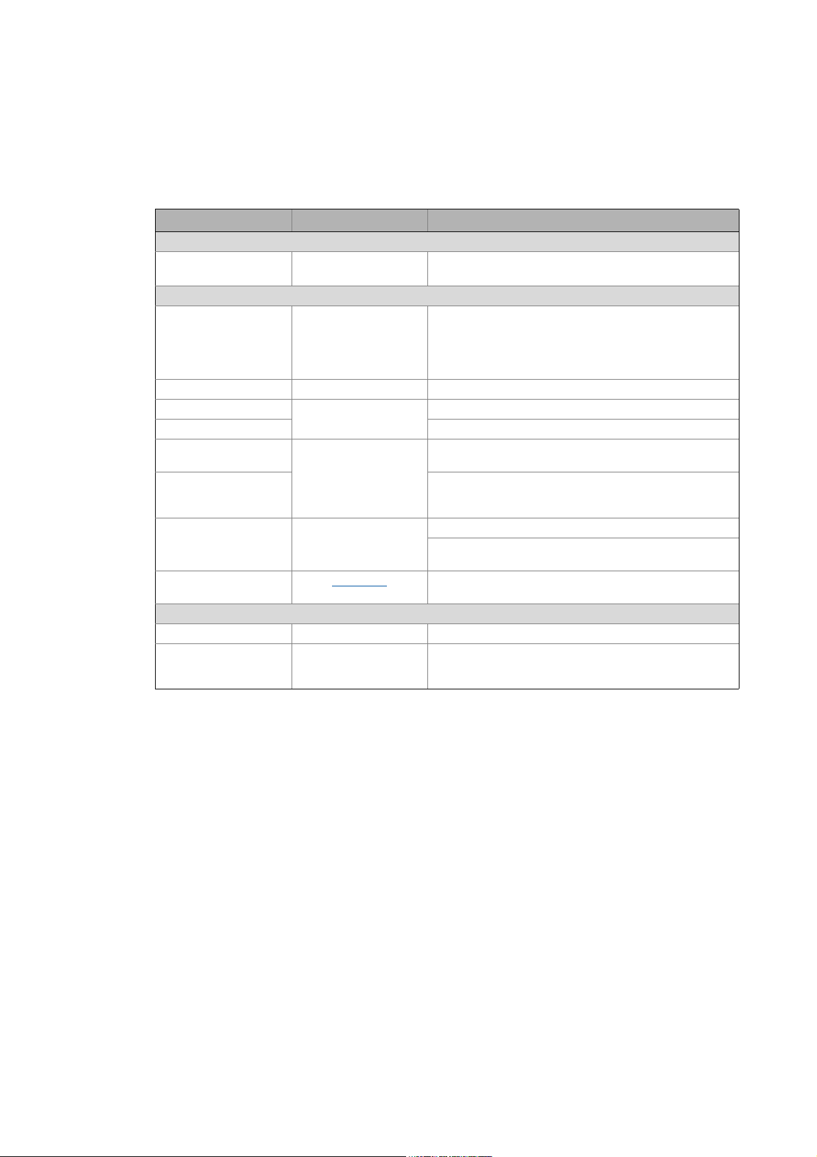
This manual is part of the "Controller-based Automation" manual collection. The manual collection
consists of the documents:
Documentation/abbreviation Subject
System manuals (SHB) • "Controller-based Automation"
Communication manuals (KHB) • "Controller-based Automation" EtherCAT®
Software manuals (SW) • Controller
• Visualization
• "Controller-based Automation" CANopen®
• "Controller-based Automation" PROFIBUS®
•»PLC Designer«
• »Engineer«
• »VisiWinNET® Smart«
•»Backup & Restore«
Information on the use of the controller beyond the field of "Controller-based
Automation" can be found in the system manuals tailored to the application case.
6 Lenze · ApplicationTemplate · 1.3 EN - 04/2013
Page 7

About this documentation
_ _ _ _ _ _ _ _ _ _ _ _ _ _ _ _ _ _ _ _ _ _ _ _ _ _ _ _ _ _ _ _ _ _ _ _ _ _ _ _ _ _ _ _ _ _ _ _ _ _ _ _ _ _ _ _ _ _ _ _ _ _ _ _
Further technical documentation on Lenze products
Further information on Lenze products which can be used in connection with "Controllerbased Automation" can be found in the following documentation:
Mounting & wiring Symbols:
MAs Controller Printed documentation
MA i700 servo inverter Online help / PDF file
MAs Servo Drives 9400
MAs Inverter Drives 8400 Abbreviation:
MA I/O system 1000 (EPM-Sxxx) BA Operating instructions
MAs for communication cards (MC-xxx) KHB Communication manual
MAs for communication modules MA Mounting instructions
SW Software manual
Parameterisation, configuration, commissioning SHB System manual
SW Controller
SW Servo-Inverter i700
SW Servo Drive 9400 HighLine/PLC /
Regenerative power supply module
9400 HighLine commissioning guidelines
SW Inverter Drives 8400
StateLine/HighLine/TopLine
SHB I/O system 1000 (EPM-Sxxx)
BAs for servo system ECS (ECSxE, ECSxM)
KHBs for communication modules
Programming
SW 9400 function library
Reuse
SW Application Sample i700
SW Application Samples
SW ApplicationTemplate
Target group
This documentation addresses to all persons who plan, commission, and program a Lenze
automation system on the basis of the Lenze "ApplicationTemplate" as part of the "Controller-based
Automation".
Screen shots/application examples
All screenshots in this documentation are application examples. Depending on the firmware
version of the Lenze device and the software version of the engineering tools installed (here: »PLC
Designer«), the representation of the actual screen display may deviate.
Lenze · ApplicationTemplate · 1.3 EN - 04/2013 7
Page 8

About this documentation
Document history
_ _ _ _ _ _ _ _ _ _ _ _ _ _ _ _ _ _ _ _ _ _ _ _ _ _ _ _ _ _ _ _ _ _ _ _ _ _ _ _ _ _ _ _ _ _ _ _ _ _ _ _ _ _ _ _ _ _ _ _ _ _ _ _
Information regarding the validity
The information in this documentation applies to the following Lenze software:
Software From software version
»PLC Designer« 3.5
Valid for the following Lenze templates:
• "ApplicationTemplate Counter" sample project: L_ApplicationTemplateCounter
• "Application Template" application template: L_ApplicationTemplate
1.1 Document history
Version Description
1.0 04/2012 TD11 First edition
1.1 07/2012 TD11 Updated to M5 of the ApplicationTemplate
• General correction
• Adaptation to VISU layout according to the Lenze programming style guide for
FBs.
1.2 11/2012 TD11 Updated to »PLC Designer« V3.3.2
• New: ApplicationTemplateCounter sample project (Lenze standard)
1.3 04/2013 TD11 Updated to »PLC Designer« V3.5
• Software update of ApplicationTemplateCounter/ApplicationTemplate.
• New: Application example "flying saw".
8
Lenze · ApplicationTemplate · 1.3 EN - 04/2013
Page 9
About this documentation
Conventions used
_ _ _ _ _ _ _ _ _ _ _ _ _ _ _ _ _ _ _ _ _ _ _ _ _ _ _ _ _ _ _ _ _ _ _ _ _ _ _ _ _ _ _ _ _ _ _ _ _ _ _ _ _ _ _ _ _ _ _ _ _ _ _ _
1.2 Conventions used
This documentation uses the following conventions to distinguish between different types of
information:
Type of information Display Examples/notes
Numbers
Decimal separator Point The decimal point is generally used.
Example: 1234.56
Text
Version information Text colour blue All pieces of information that only apply to or from a certain
Program name » « »PLC Designer«...
Window Italics The Message window... / The Options ... dialog box
Variable name By setting bEnable to TRUE...
Control element Bold The OK... button / The Copy... command / The Properties...
Sequence of menu
commands
Shortcut <Bold> Use <F1> to open the online help.
Hyperlink underlined
Symbols
Page reference ( 9) Reference to further information: Page number in PDF file.
Step-by-step instructions
controller software version are identified accordingly in this
documentation.
Example: This function extension is available as from
software version V3.0!
tab / The Name ... input field
If the execution of a function requires several commands in
a row, the individual commands are separated by an arrow:
Select File
If a key combination is required for a command, a "+" is
placed between the key identifiers: With <Shift>+<ESC>...
Reference to further information: Hyperlink to further
information.
Step-by-step instructions are marked by a pictograph.
Open to...
Lenze · ApplicationTemplate · 1.3 EN - 04/2013 9
Page 10

About this documentation
Notes used
_ _ _ _ _ _ _ _ _ _ _ _ _ _ _ _ _ _ _ _ _ _ _ _ _ _ _ _ _ _ _ _ _ _ _ _ _ _ _ _ _ _ _ _ _ _ _ _ _ _ _ _ _ _ _ _ _ _ _ _ _ _ _ _
1.3 Notes used
The following signal words and icons are used in this documentation to indicate dangers and
important information:
Safety instructions
Structure of safety instructions:
Pictograph and signal word!
(characterises the type and severity of danger)
Note
(describes the danger and explains how to avoid it.)
Pictograph Signal word Meaning
Danger! Danger of personal injuries through electrical voltage
Danger! Danger of personal injury through a general source of danger
Stop! Danger of damage to material assets
Reference to an imminent danger that may result in death or serious
personal
injury unless the corresponding measures are taken.
Reference to an imminent danger that may result in death or serious
personal
injury unless the corresponding measures are taken.
Indicates a potential danger that may lead to material damage unless the
corresponding measures are taken.
Application notes
Pictograph Signal word Meaning
Note! Important note for trouble-free operation
Tip! Useful tip for easy handling
Reference to other documents
10
Lenze · ApplicationTemplate · 1.3 EN - 04/2013
Page 11
About this documentation
Terminology used (presented according to the order in the device view)
_ _ _ _ _ _ _ _ _ _ _ _ _ _ _ _ _ _ _ _ _ _ _ _ _ _ _ _ _ _ _ _ _ _ _ _ _ _ _ _ _ _ _ _ _ _ _ _ _ _ _ _ _ _ _ _ _ _ _ _ _ _ _ _
1.4 Terminology used (presented according to the order in the device view)
Term/abbreviation Position in the device view Function
Machine module tree
MMT
ModuleApplicationCalls
MAC
Machine module
MM
Machine module
application
MAP
Machine function block
MFB
A10_MachineModuleTree
A11_ModuleAppCalls
A70_MachineModuleSources
The "MachineModuleTree" (MMT) maps the
structure of the automation system in the form of
machine modules.
• In the "MachineModuleTree", all machine
modules required for the machine are
interconnected hierarchically according to the
mechatronic interaction.
The module applications are to be assigned to the
corresponding task within the
"ModuleApplicationCalls".
• Thus it is defined which module application is to
be processed within the individual tasks.
A machine module maps a unit of the real machine
structure in the »PLC Designer«.
• The machine module is part of the
MachineModuleTree(MMT) within which the
individual machine modules are
interconnected.
The machine module application provides the
functionality of a machine module.
• A machine module can contain one or several
machine module applications.
The machine function block represents the
machine module in the machine module tree
(MMT).
Lenze · ApplicationTemplate · 1.3 EN - 04/2013 11
Page 12

Safety instructions
_ _ _ _ _ _ _ _ _ _ _ _ _ _ _ _ _ _ _ _ _ _ _ _ _ _ _ _ _ _ _ _ _ _ _ _ _ _ _ _ _ _ _ _ _ _ _ _ _ _ _ _ _ _ _ _ _ _ _ _ _ _ _ _
2 Safety instructions
Please observe the following safety instructions when you want to commission a controller or
system.
Read the documentation supplied with the controller or the individual components of
the system carefully before you start to commission the devices!
The device documentation contains safety instructions which must be observed!
Danger!
According to today's scientific knowledge it is not possible to ensure absolute freedom
from defects of a software.
If required, systems with integrated controllers have to be equipped with additional
monitoring and protective equipment in accordance with the safety regulations valid in
each case (e.g. law on technical equipment, regulations for the prevention of accidents),
so that an impermissible operating status does not endanger persons or equipment.
During commissioning persons must keep a safe distance from the motor or the
machine parts driven by the motor. Otherwise there would be a risk of injury by the
moving machine parts.
Stop!
If you cha nge par ameter s in the »PLC De signer« whil e an onl ine con nectio n to the devic e
is established, the changes are directly accepted in the device!
An incorrect parameterisation can result in unpredictable motor movements. By an
unintentional direction of rotation, too high speeds or jerky operation, powered
machine parts can be damaged!
12 Lenze · ApplicationTemplate · 1.3 EN - 04/2013
Page 13
Requirements
System requirements
_ _ _ _ _ _ _ _ _ _ _ _ _ _ _ _ _ _ _ _ _ _ _ _ _ _ _ _ _ _ _ _ _ _ _ _ _ _ _ _ _ _ _ _ _ _ _ _ _ _ _ _ _ _ _ _ _ _ _ _ _ _ _ _
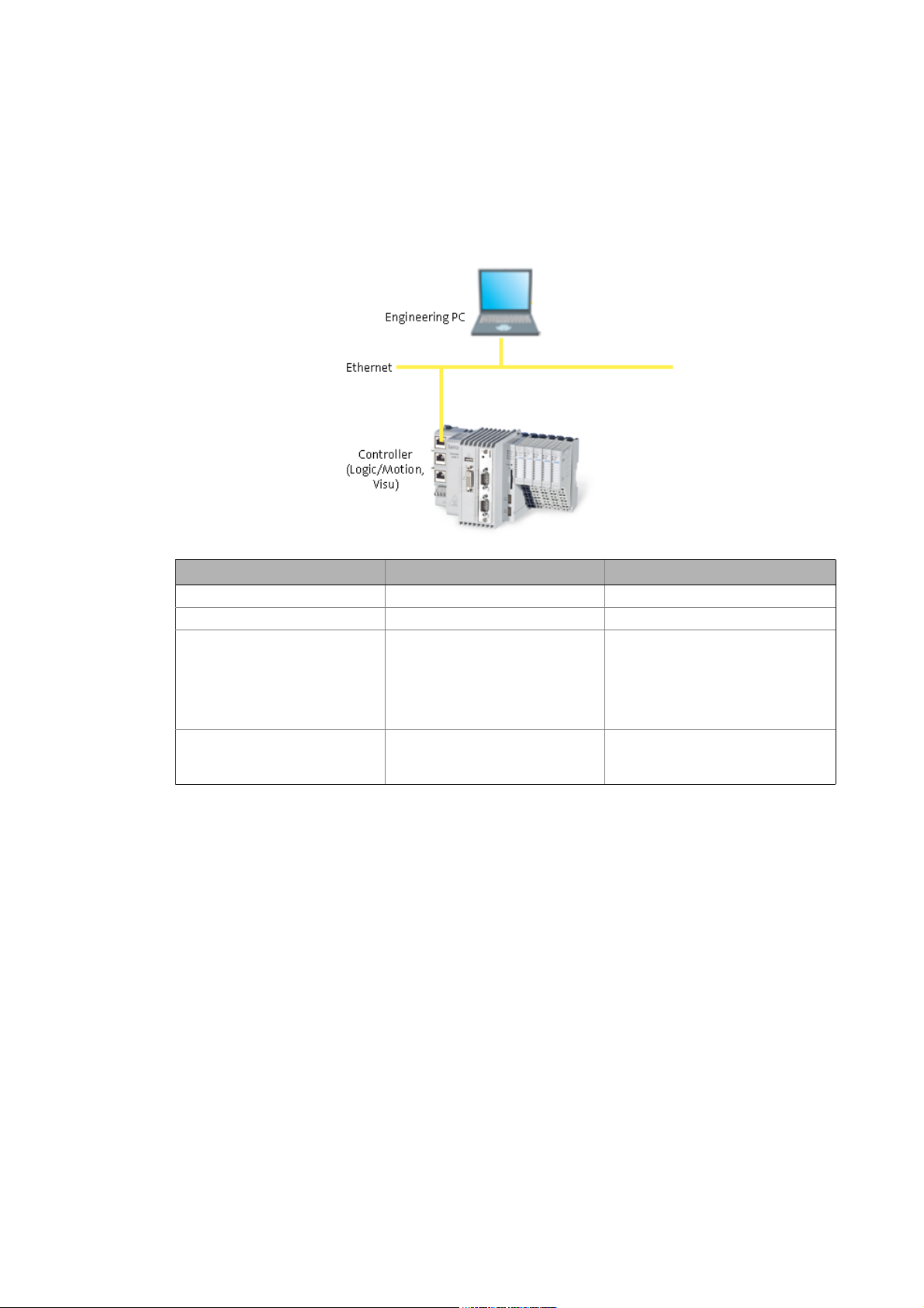
3 Requirements
3.1 System requirements
Engineering PC Controller
Hardware PC/notebook PLC (Logic) from firmware V3.3
Operating system Windows XP Windows CE
Required Lenze software »PLC Designer« from V3.3
•Contains the
ApplicationTemplate
• Contains the Lenze library
"L_EATP_ApplicationTemplate.co
mpiled-library"
Further requirements - Depending on the application case:
3.2 Establishing communication with the controller
• Connect the Engineering PC with the controller via a network cable. The »PLC Designer«
accesses the controller via Ethernet.
• Make the IP settings with the »PLC Designer«.
How to check the communication settings:
1. Double-click the desired controller in the Devices view.
2. Make the desired settings on the Communication settings tab.
•Click the Add gateway button to insert a gateway.
Runtime software
•Logic
• Motion (this requires updating the
project information: "Update
devices")
• CAN or EtherCAT bus system
• CAN or EtherCAT node
Lenze · ApplicationTemplate · 1.3 EN - 04/2013 13
Page 14
Requirements
Establishing communication with the controller
_ _ _ _ _ _ _ _ _ _ _ _ _ _ _ _ _ _ _ _ _ _ _ _ _ _ _ _ _ _ _ _ _ _ _ _ _ _ _ _ _ _ _ _ _ _ _ _ _ _ _ _ _ _ _ _ _ _ _ _ _ _ _ _
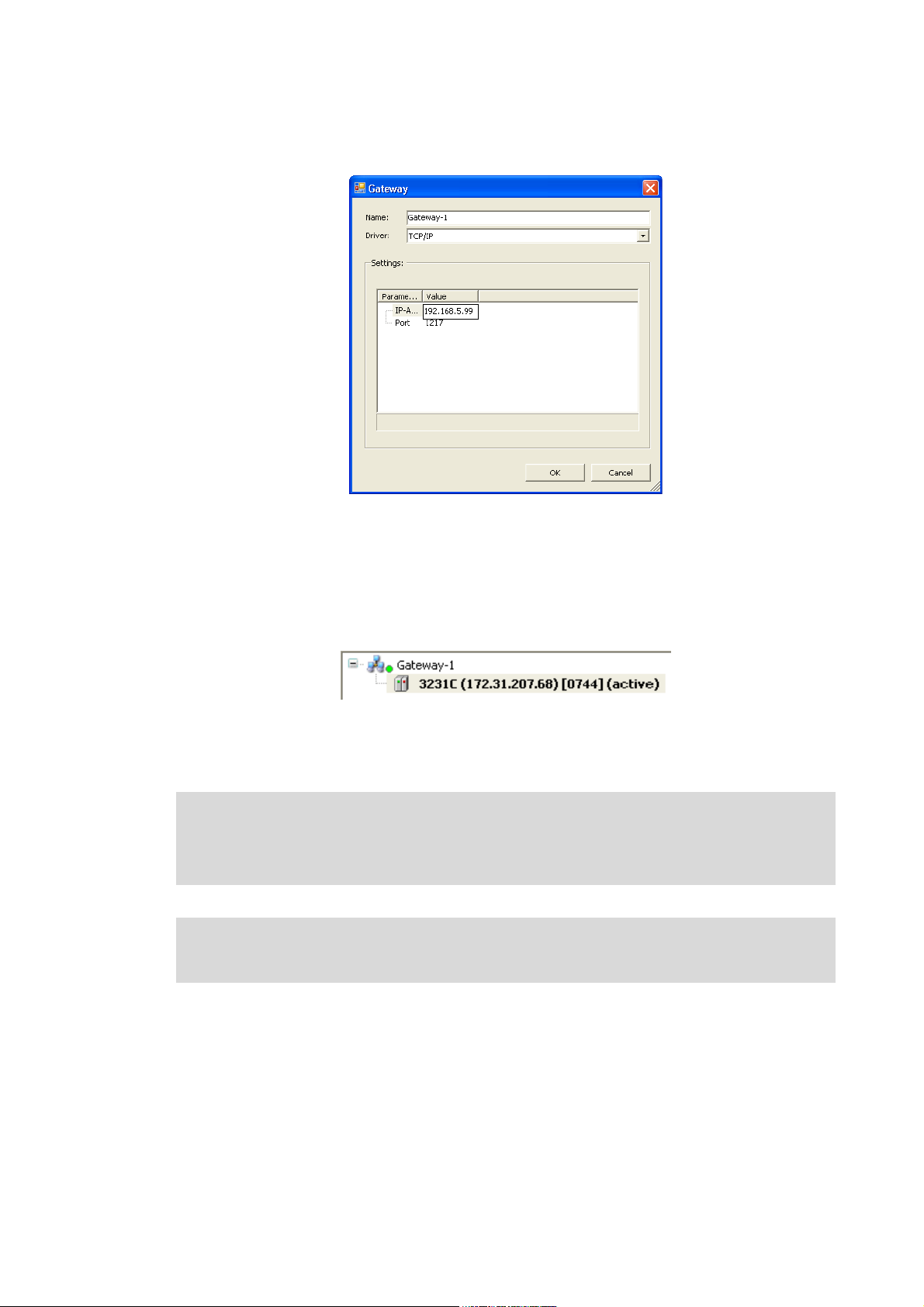
•Enter the desired IP address of the controller.
[3-1] Example: Enter the IP address of the controller.
3. Click OK to add the controller as gateway.
4. By double-clicking the desired channel (or clicking the Set active path button), set the
channel selected in the device view below the gateway as active path to the controller.
• Thus, all communication actions directly refer to this channel.
• The currently active path is represented in bold in the list and "(active)" is attached:
5. A device represented in italics is set as active path but has not been found during the last
network scan.
Note!
• During initial commissioning, observe the following predefined IP addresses of the
controllers:: 192.168.5.99
Further information can be found in the following documentation:
• Controller - Parameter setting & configuration
14
Lenze · ApplicationTemplate · 1.3 EN - 04/2013
Page 15

What is the ApplicationTemplate?
Objective of the ApplicationTemplate
_ _ _ _ _ _ _ _ _ _ _ _ _ _ _ _ _ _ _ _ _ _ _ _ _ _ _ _ _ _ _ _ _ _ _ _ _ _ _ _ _ _ _ _ _ _ _ _ _ _ _ _ _ _ _ _ _ _ _ _ _ _ _ _
4 What is the ApplicationTemplate?
The ApplicationTemplate is a Lenze application template for standardised and convenient
programming in the »PLC Designer«.
• The ApplicationTemplate is included in the »PLC Designer« (from version 3.3) as project
template. Create a new project - open the ApplicationTemplate
•The L_EATP_ApplicationTemplate.compiled-library library includes the structure and the basic
functionality of the ApplicationTemplate. The L_EATP_ApplicationTemplate library
4.1 Objective of the ApplicationTemplate
The ApplicationTemplate...
• ...helps to implement the mechatronic structure of an automation system (which is available as
a tree structure) in a modular manner.
• ...enables the integration of predefined machine modules with prepared applications (for
instance a cross cutter).
• ...simplifies and speeds up the creation of PLC programs in the long term by re-use of a
standardised and modularised folder structure.
( 31)
( 110)
What are the advantages of the ApplicationTemplate?
The ApplicationTemplate facilitates programming with the »PLC Designer« ...
• ...by a predefined folder structure which "cleans up" and which can be extended individually.
• ...renders the navigation for extending or creating machine programming easier.
• The ApplicationTemplate contains ready-made, re-usable machine modules and module
applications which minimise the risk of compilation errors in order to thus reduce time and
costs.
Lenze · ApplicationTemplate · 1.3 EN - 04/2013 15
Page 16

What is the ApplicationTemplate?
Features of the ApplicationTemplate at a glance
_ _ _ _ _ _ _ _ _ _ _ _ _ _ _ _ _ _ _ _ _ _ _ _ _ _ _ _ _ _ _ _ _ _ _ _ _ _ _ _ _ _ _ _ _ _ _ _ _ _ _ _ _ _ _ _ _ _ _ _ _ _ _ _
4.2 Features of the ApplicationTemplate at a glance
The following functions facilitate implementing a machine application in a PLC:
State machine
Error handling ( 92)
Multitasking ( 98)
Further advantages if the ApplicationTemplate is used:
( 21)
• Consistent data transfer
• Diagnostic function for every machine module ("generic module diagnosis").
• A defined standard response ("DefaultCoupling") of the state machine. Default coupling
( 83)
• Decouples one (or several machine modules.Internal Control ( 101)
For more information on the respective functions, please see the corresponding subchapter.
between the tasks.
16
Lenze · ApplicationTemplate · 1.3 EN - 04/2013
Page 17
What is the ApplicationTemplate?
Elements of the ApplicationTemplate
_ _ _ _ _ _ _ _ _ _ _ _ _ _ _ _ _ _ _ _ _ _ _ _ _ _ _ _ _ _ _ _ _ _ _ _ _ _ _ _ _ _ _ _ _ _ _ _ _ _ _ _ _ _ _ _ _ _ _ _ _ _ _ _
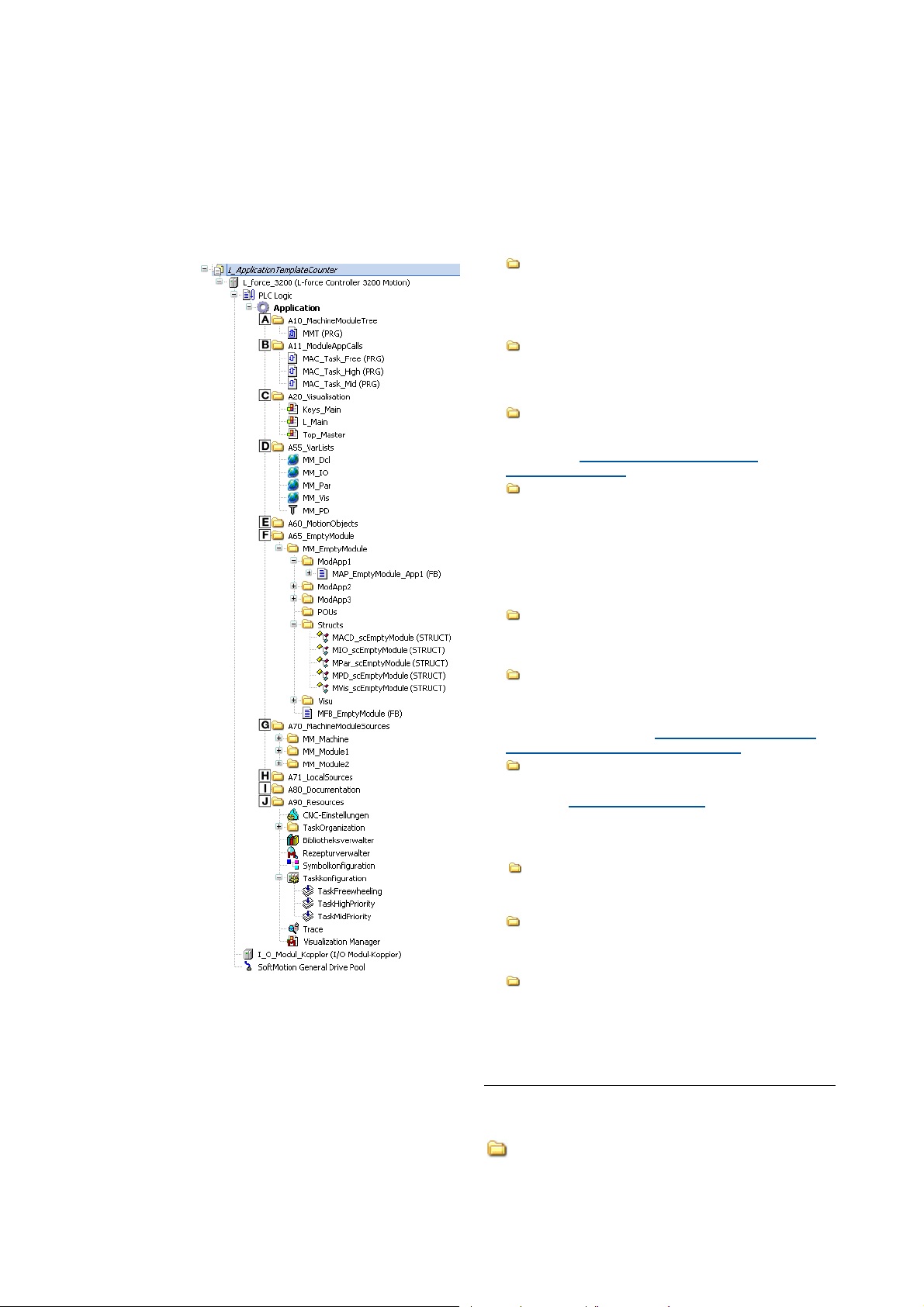
4.3 Elements of the ApplicationTemplate
4.3.1 Machine Module Tree - MMT
In order to map the desired automation system in the »PLC Designer« on the basis of the
ApplicationTemplate, the structure of the whole machine application must be created in the »PLC
Designer«.
• In a first step, the machine structure must be divided into machine modules.
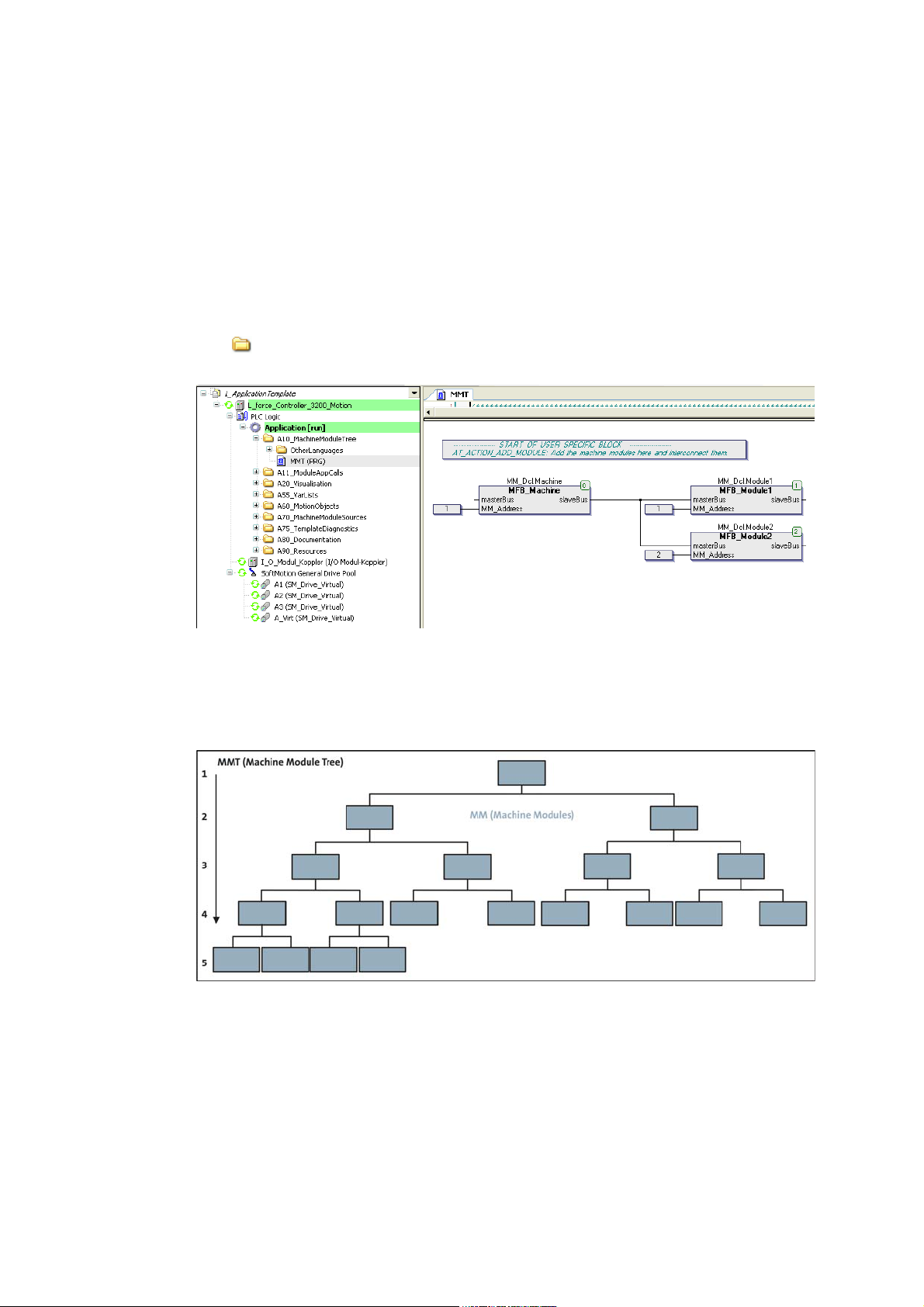
•The A10_MachineModuleTree machine module tree (MMT) shows the machine modules in
the form of a tree structure from left to right.
[4-1] Machine structure tree (MMT) in the ApplicationTemplateCounter, A10_MachineModuleTree folder
The ApplicationTemplate...
• ...supports two to five hierarchy levels of machine modules.
• ...supports up to 30 machine modules.
[4-2] MMT (Machine Module Tree) with up to five possible hierarchy levels of machine modules
Lenze · ApplicationTemplate · 1.3 EN - 04/2013 17
Page 18
What is the ApplicationTemplate?
Elements of the ApplicationTemplate
_ _ _ _ _ _ _ _ _ _ _ _ _ _ _ _ _ _ _ _ _ _ _ _ _ _ _ _ _ _ _ _ _ _ _ _ _ _ _ _ _ _ _ _ _ _ _ _ _ _ _ _ _ _ _ _ _ _ _ _ _ _ _ _
4.3.2 Machine modules (MM)
The overall functionality of the automation system is structured in a modular manner in the
ApplicationTemplate. This means that every subfunction of the machine is included in one of the
machine modules. Due to the modular structure, individual (or multiple) subfunctions of a machine
can be reused
machine parts.
• A machine module represents the function of a machine part; for instance a conveying belt, or
a cross cutter.
• The overall functionality of, for example, a bag form, fill, and seal machine, contains the "Cross
cutter" and "Transport unit" subfunctions. The two subfunctions are to be converted to a
separate machine module each.
Machine module in the ApplicationTemplate
. Advantage: The respective function does not have to be recreated for further
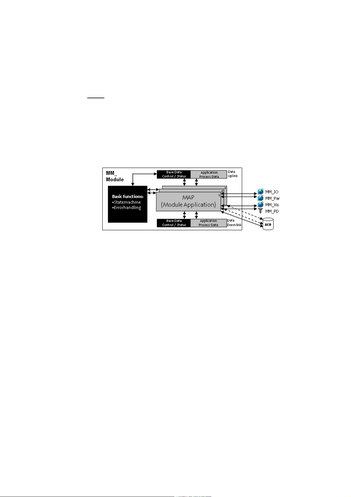
[4-3] Structure of a machine module
• Every machine module contains the BaseChannel ("Base Data") which serves as a data
channel for the basic functions of the ApplicationTemplate.
• The basic functions of the ApplicationTemplate are the State machine and the Error handling.
Every machine module has an AppChannelData structure (ACD structure). An ACD structure can be
defined in a machine module if necessary.
• Via the ACD structure, data are provided to/received from the higher-level machine module.
• Via the ACD structure, process data can be exchanged between the user's own module
applications.
A machine module (MFB) always contains at least one module application (MAP). Up to three MAPs
per MFB are possible.
•Via the MM_IO, MM_Par; MM_Vis, MM_PD structures, the module application (MAP) is to be
connected to the "outside world" (the respective sub-function of the automation system).
•By means of the MM_IO structure, the inputs/outputs of the terminals/the fieldbus are to be
connected.
•The MM_Par structure contains all variables that are to be managed by the recipe manager.
•The MM_Vis structure contains all variables that can be controlled or are to be displayed via an
external visualization.
•The MM_PD structure contains all persistent variables.
18
Lenze · ApplicationTemplate · 1.3 EN - 04/2013
Page 19
What is the ApplicationTemplate?
Elements of the ApplicationTemplate
_ _ _ _ _ _ _ _ _ _ _ _ _ _ _ _ _ _ _ _ _ _ _ _ _ _ _ _ _ _ _ _ _ _ _ _ _ _ _ _ _ _ _ _ _ _ _ _ _ _ _ _ _ _ _ _ _ _ _ _ _ _ _ _
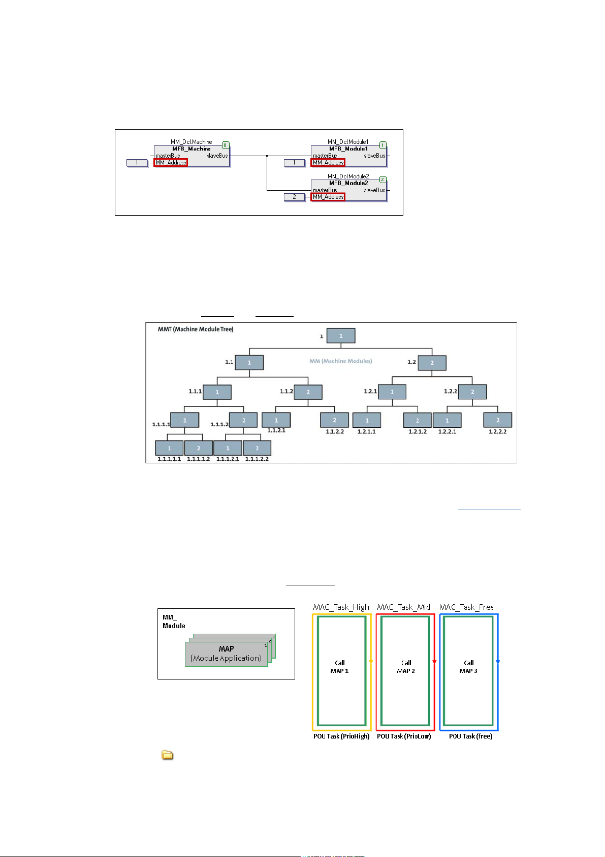
4.3.3 Addressing the machine modules
Every machine module has an
MM_Address input which
serves to assign the relative
address to the machine
module.
[4-4] Illustration: Sample illustration MMT in the sample project L_ApplicationTemplateCounter
The following must be observed when relative addresses are assigned to the machine modules:
•The relative address is to be assigned to every machine module (value range: 1...29).
• During the initialisation phase, the »PLC Designer« generates an absolute address for every
machine module.
• Example of the relative
The diagram shows the absolute module address (black) and the relative module address (white).
• In the event of an error, the absolute address enables an error analysis. This for instance makes
it possible to retrace the module which has caused the error in each case. Error handling
4.3.4 Module application (MAP)
The module application (MAP) contains the function of the corresponding machine module.
• The ApplicationTemplate supports up to three
machine module.
and absolute module addressing:
( 92)
tasks. Hence, up to three MAPs can be used per
•In the A11_ModuleAppCalls folder, the MAPs are to be assigned to the tasks:
ModuleAppCalls (MAC).
Lenze · ApplicationTemplate · 1.3 EN - 04/2013 19
Page 20
What is the ApplicationTemplate?
Elements of the ApplicationTemplate
_ _ _ _ _ _ _ _ _ _ _ _ _ _ _ _ _ _ _ _ _ _ _ _ _ _ _ _ _ _ _ _ _ _ _ _ _ _ _ _ _ _ _ _ _ _ _ _ _ _ _ _ _ _ _ _ _ _ _ _ _ _ _ _
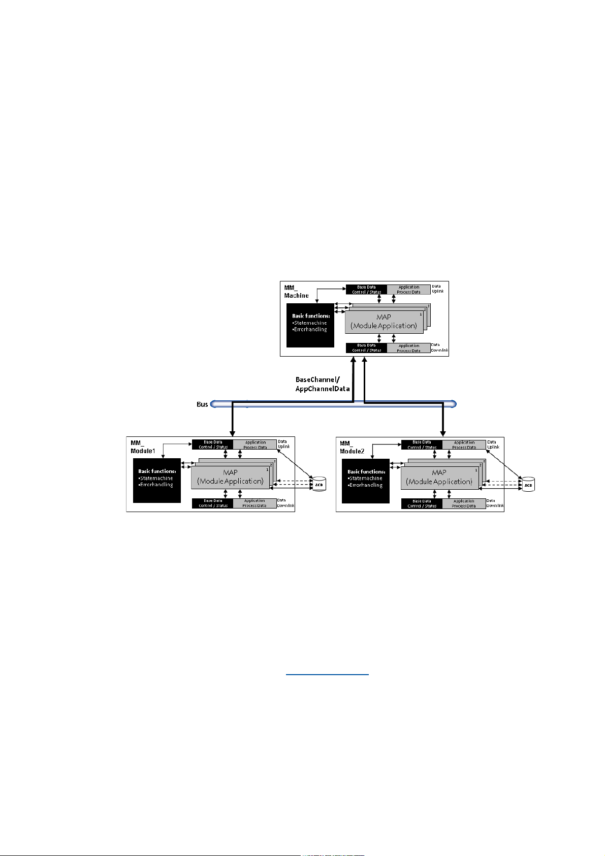
4.3.5 Communication between the machine modules
The machine modules (MM_xxx) communicate with each other via the MM_Machine machine
control module by means of the BaseChannel communication channel and the AppChannelData
structure.
• The communication channels provide for a bidirectional data exchange.
• The BaseChannel is defined as a structure in the ApplicationTemplate.
One or several slave modules are always exactly connected to one higher-level master module.
However, the master only always communicates with one slave module. Slave modules cannot
communicate directly with each other, but only via the higher-level master module.
The higher-level machine module (master) communicates with the lower-level machine modules
(slaves) via data channels (channels). During the initialisation, the ApplicationTemplate generates
a BaseChannel and an AppChannelData(ACD) structure.
[4-5] Exchange of information between the machine modules (L_ApplicationTemplateCounter)
BaseChannel: exchange of control and status data (Control/Status basic data)
The BaseChannel...
• ...contains the control / status information of the state machine.
• ...contains the error handling.
The ACD structure...
• ...serves to exchange application process data between machine modules.
• ...is a data structure for the definition of own process data.
• ...must always be derived from the L_EATP_ACD_Base
structure.
20
Lenze · ApplicationTemplate · 1.3 EN - 04/2013
Page 21
What is the ApplicationTemplate?
Elements of the ApplicationTemplate
_ _ _ _ _ _ _ _ _ _ _ _ _ _ _ _ _ _ _ _ _ _ _ _ _ _ _ _ _ _ _ _ _ _ _ _ _ _ _ _ _ _ _ _ _ _ _ _ _ _ _ _ _ _ _ _ _ _ _ _ _ _ _ _
4.3.6 State machine
Every machine module features one state machine. State machine ( 77)
• If a machine module is integrated in the machine module tree (if it is not decoupled from the
MMT), the state machine of the master module controls all state machines of the lower-level
machine modules.
• When all slave modules have changed to the requested state, the master module also changes
to the requested state.
Exception: During the initialisation, all machine modules are in the "INIT" state and,
independently of the slave or master, change to the "READY" state if it is enabled:
SMEnableInitToReady(TRUE);
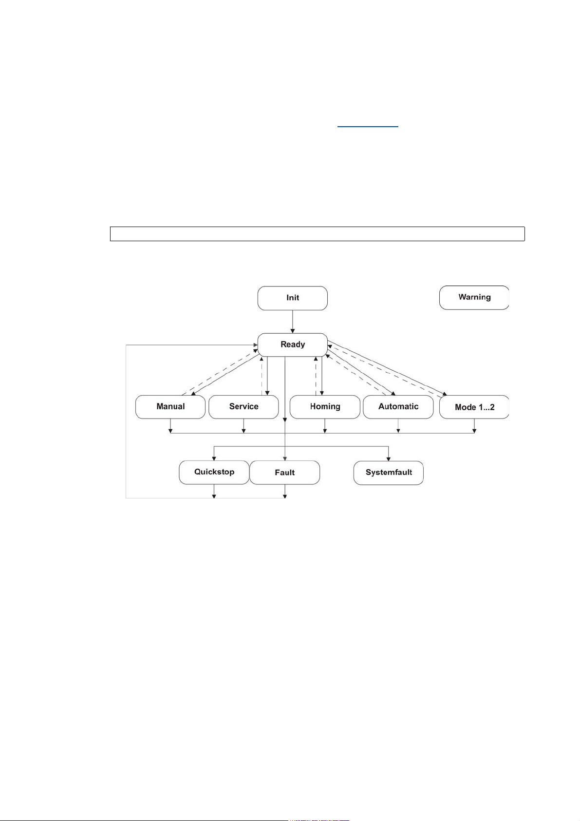
State transitions - overview
The following status diagram illustrates the possible operating states of the state machine:
• After the start (switch-on / re-initialisation), the module is in the "Init" state.
• In standby/waiting mode, the module is in the "Ready" state.
• "Warning" is a special status (independent, "orthogonal" state), which does not influence the
operational performance of the machine module.
Lenze · ApplicationTemplate · 1.3 EN - 04/2013 21
Page 22

What is the ApplicationTemplate?
Elements of the ApplicationTemplate
_ _ _ _ _ _ _ _ _ _ _ _ _ _ _ _ _ _ _ _ _ _ _ _ _ _ _ _ _ _ _ _ _ _ _ _ _ _ _ _ _ _ _ _ _ _ _ _ _ _ _ _ _ _ _ _ _ _ _ _ _ _ _ _
4.3.7 Error handling
The error handling of the ApplicationTemplate provides mechanisms by means of which responses
(errors, warnings, messages) can be defined and triggered in the module applications (MAP) of the
machine modules (MM)
Further mechanisms are:
• The forwarding of error states in the MachineModuleTree (MMT).
• An application-global error list with the current error status of all machine modules contained
in the MMT.
• Transmission of errors and events to the central logbook of the controller.
Further information can be found under: Error handling
( 92)
22
Lenze · ApplicationTemplate · 1.3 EN - 04/2013
Page 23
Structuring the automation system: Standard procedure
_ _ _ _ _ _ _ _ _ _ _ _ _ _ _ _ _ _ _ _ _ _ _ _ _ _ _ _ _ _ _ _ _ _ _ _ _ _ _ _ _ _ _ _ _ _ _ _ _ _ _ _ _ _ _ _ _ _ _ _ _ _ _ _
5 Structuring the automation system: Standard procedure
This section describes the standard procedure to create an application with the »PLC Designer«
based on the ApplicationTemplate.
• Use the following recommendations as a guide in order to be able to then create a PLC project
in the »PLC Designer« in a structured manner using the ApplicationTemplate and to program it
effectively.
• Due to the structured layout of the ApplicationTemplate (the consistency in these structures
and the compliance with these structures), applications can be created more quickly and hence
integrated in an existing PLC program more quickly.
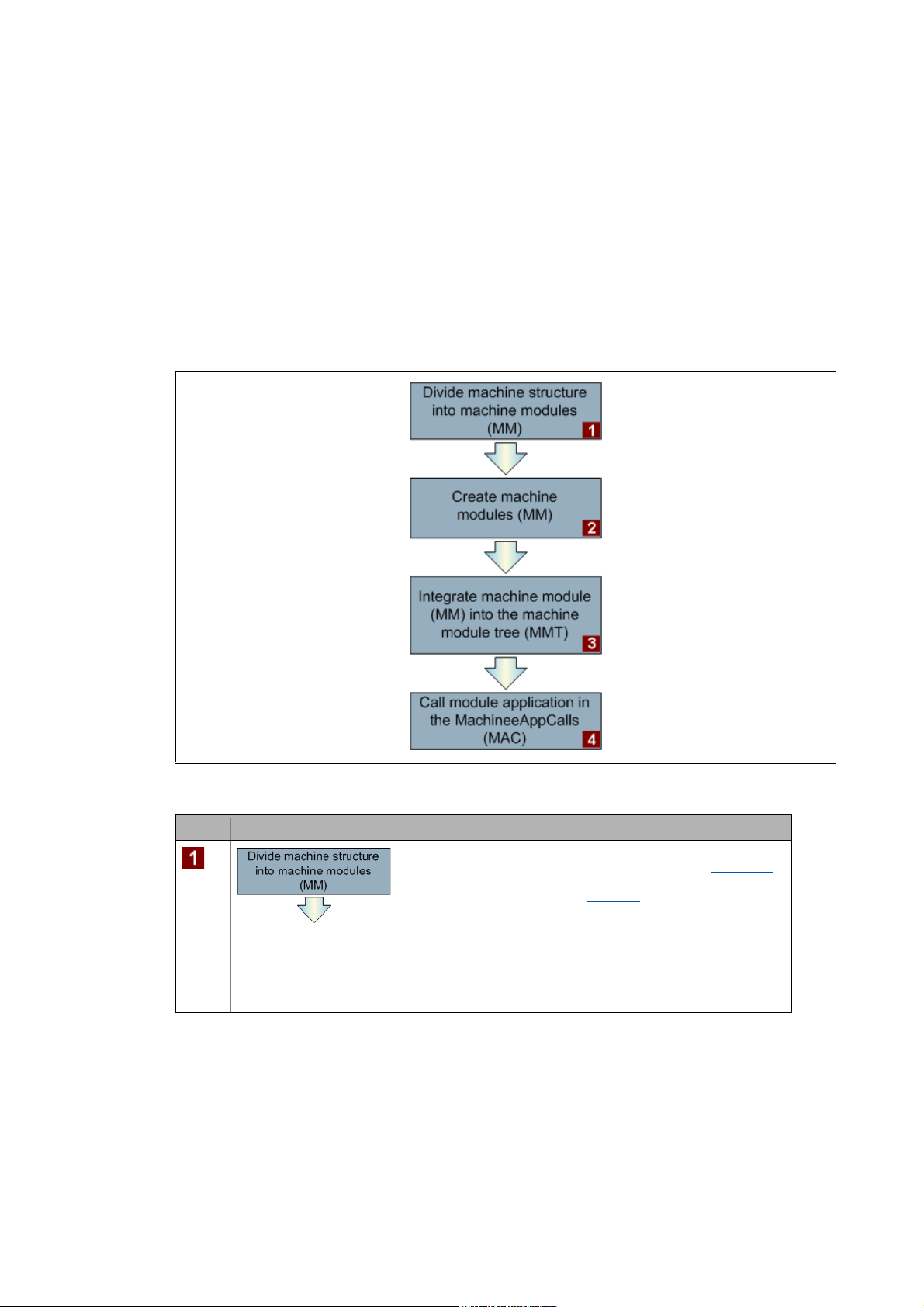
[5-1] Recommended procedure for creating a project efficiently.
Step Action What has to be done? Description
Gain an overview of the
overall functionality of the
machine structure.
• Divide the overall
functionality of the
machine structure into
subfunctions.
• Transfer the identified
subfunctions of the
machine structure to
machine modules.
In this project phase, programming
is not yet required! Assign the
relative address to the machine
modules. ( 25)
Lenze · ApplicationTemplate · 1.3 EN - 04/2013 23
Page 24
Structuring the automation system: Standard procedure
_ _ _ _ _ _ _ _ _ _ _ _ _ _ _ _ _ _ _ _ _ _ _ _ _ _ _ _ _ _ _ _ _ _ _ _ _ _ _ _ _ _ _ _ _ _ _ _ _ _ _ _ _ _ _ _ _ _ _ _ _ _ _ _
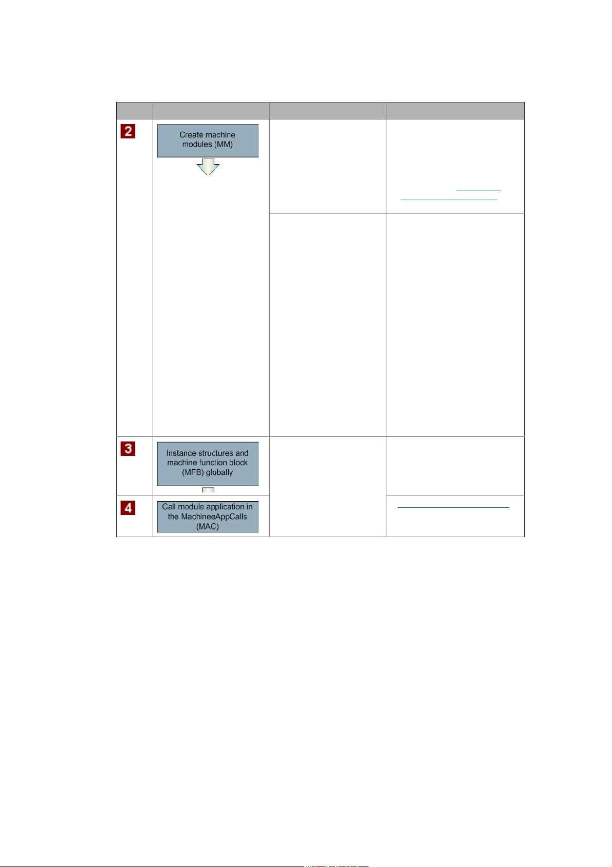
Step Action What has to be done? Description
Create machine modules
containing the subfunctions
of the machine structure in
each case: one subfunction =
one machine module.
• Define the interfaces for
the module applications
(MAPs).
• Optionally create the
visualization for the
respective machine
module.
• Each machine module is
provided with a state
machine. Irrespective of
the active status, the
module application (MAP)
calls a corresponding
action. The action is
subordinated to the
module application.
• Within these actions,
create the logic which is to
be executed if the
machine module (MM) is
in the corresponding
status.
• In order to be able to call
machine functions in different
tasks, corresponding module
applications have to be created.
• More information about
structuring within a module
application: Structuring
within a machine module
( 26)
• Define variables.
• Declare variables in the
(MM_IO, MM_Par, MM_Vis,
MM_PD) variable lists.
• Integrate newly created
machine modules into the MMT
(machine module tree).
• Assign the relative address to
the machine modules.
Creating module applications
( 62)
24 Lenze · ApplicationTemplate · 1.3 EN - 04/2013
Page 25
Structuring the automation system: Standard procedure
Assign the relative address to the machine modules.
_ _ _ _ _ _ _ _ _ _ _ _ _ _ _ _ _ _ _ _ _ _ _ _ _ _ _ _ _ _ _ _ _ _ _ _ _ _ _ _ _ _ _ _ _ _ _ _ _ _ _ _ _ _ _ _ _ _ _ _ _ _ _ _
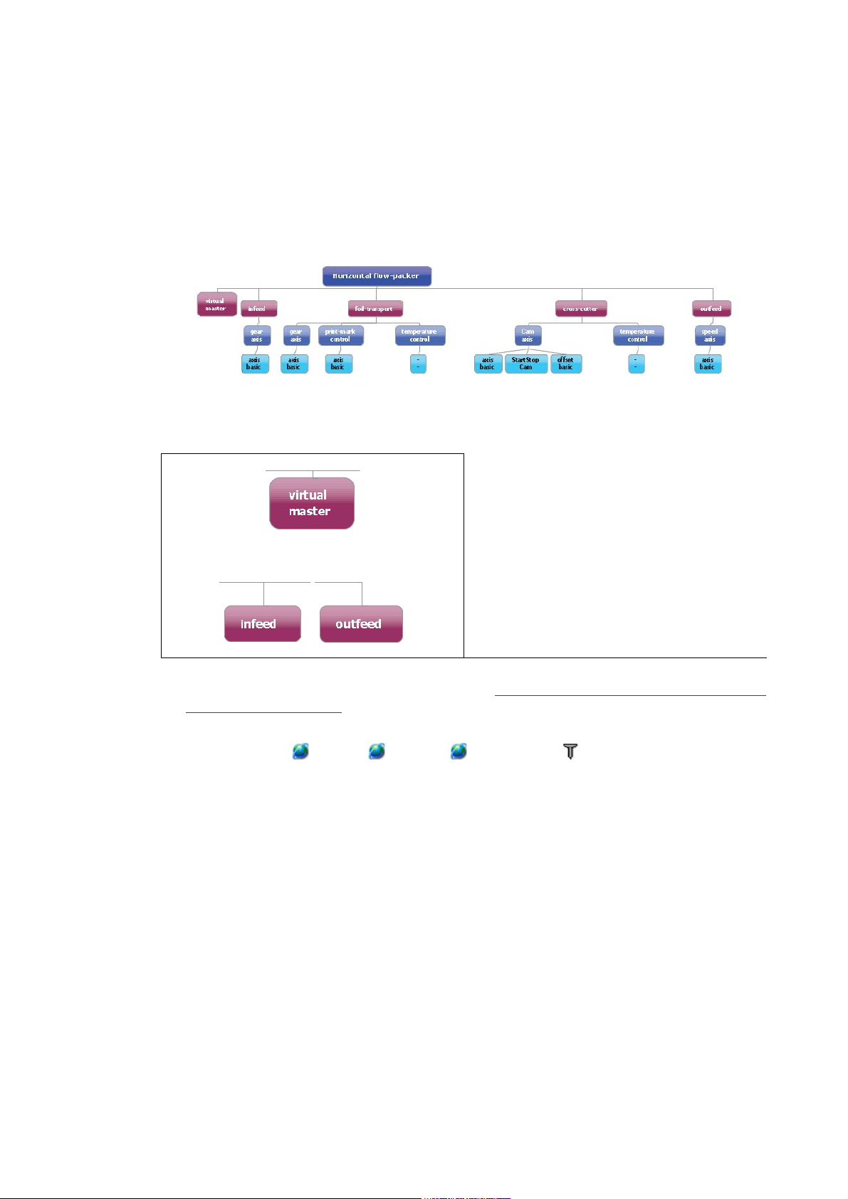
5.1 Assign the relative address to the machine modules.
In order to modularise programming of a machine system, the individual subfunctions of the overall
functionality of the automation system have to be mapped in the form of machine modules.
Example: Bag form, fill, and seal machine ("Flow Packer")
• It is helpful to outline the machine structure with t he indi vidual subfun ctions in a tree st ructur e.
• For this, the individual sub functions of the machine have to be transferred to corresponding
machine modules.
Examples of machine modules
•"Virtual master"
•"Infeed" (feeder)
•"Outfeed" (extractor)
• If the individual subfunctions are structured in the form of machine modules, the interfaces are
to be assigned to the module application (MAP).Creating your own machine modules: Copy/
insertMM_EmptyModule ( 51)
• Assign the input and output variables...
...in variable lists MM_IO, MM_Par, MM_Visu and MM_PD and
...to the variables of the AppChannelData (ACD) structure.
Lenze · ApplicationTemplate · 1.3 EN - 04/2013 25
Page 26
Structuring the automation system: Standard procedure
Structuring within a machine module
_ _ _ _ _ _ _ _ _ _ _ _ _ _ _ _ _ _ _ _ _ _ _ _ _ _ _ _ _ _ _ _ _ _ _ _ _ _ _ _ _ _ _ _ _ _ _ _ _ _ _ _ _ _ _ _ _ _ _ _ _ _ _ _
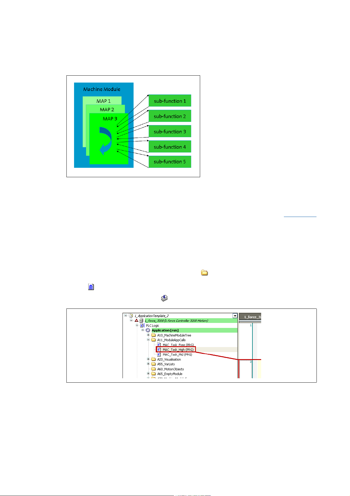
5.2 Structuring within a machine module
In order to create a clearly arranged
module application, it is advisable to
divide the module applications (MAP)
into subfunctions and to structure
them correspondingly.
5.2.1 Assigning the MAP subfunctions to individual tasks
In a first step, the functions are to be assigned to the individual tasks. The ApplicationTemplate
supports multitasking with three tasks. More information can be found under: Multitasking
( 98)
• Task "High" (standard value: 2 ms)
• Task "Mid" (standard value: 6 ms)
• Task "Free" (unsolicited)
One module application can be used per task.
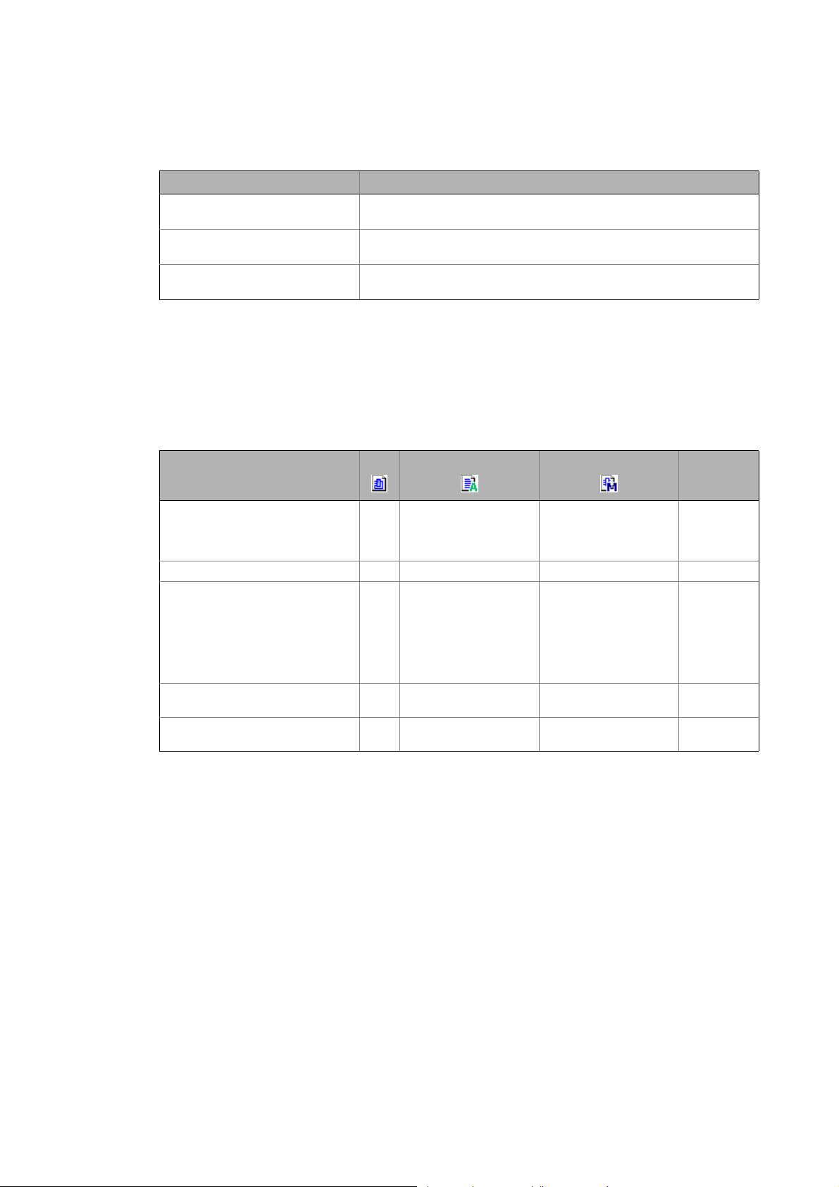
• Task and module application are assigned in the A11_ModuleAppCalls folder.
•The MAC_Task_High program part for instance calls all module applications which are to
pass through a high priority task Task_High.
[5-2] ApplicationTemplateCounter sample project: MAC_Task_High calls the Module1_App1 module application.
26
Lenze · ApplicationTemplate · 1.3 EN - 04/2013
Page 27
Structuring the automation system: Standard procedure
Structuring within a machine module
_ _ _ _ _ _ _ _ _ _ _ _ _ _ _ _ _ _ _ _ _ _ _ _ _ _ _ _ _ _ _ _ _ _ _ _ _ _ _ _ _ _ _ _ _ _ _ _ _ _ _ _ _ _ _ _ _ _ _ _ _ _ _ _
Recommendation - which function is to be called in which task?
Task/priority Function (example)
"High"
HighPriority
"Mid"
MidPriority
"Free"
Unsolicited
5.2.2 Programming recommendations for structuring
The following table presents the structuring possibilities of the ApplicationTemplate as a decision
recommendation:
Which features of the ApplicationTemplate should I use and for what purpose?
Execution of Motion functions
Conversion for an external visualization
NRT Ethernet communication
What do you want to do? FB Action Method More suitable
Work with local variables z Local variables are to be
Debugging zzNo local variables Action, FB
Reuse:
In the event of an error (when
creating the user software), error
handling can be executed at one
point.
Instancing z --Action,
Access all data types zz zAction, FB,
z - To a limited extent - for
declared in the FB
assigned.
Local variables (if
possible) are to be
declared in the FB
assigned.
instance if FBs are
integrated in the
method.
Example: "Statemachine"
in the
ApplicationTemplate
is...
-
FB
method
method
Lenze · ApplicationTemplate · 1.3 EN - 04/2013 27
Page 28
Structuring the automation system: Standard procedure
Structuring within a machine module
_ _ _ _ _ _ _ _ _ _ _ _ _ _ _ _ _ _ _ _ _ _ _ _ _ _ _ _ _ _ _ _ _ _ _ _ _ _ _ _ _ _ _ _ _ _ _ _ _ _ _ _ _ _ _ _ _ _ _ _ _ _ _ _
Actions
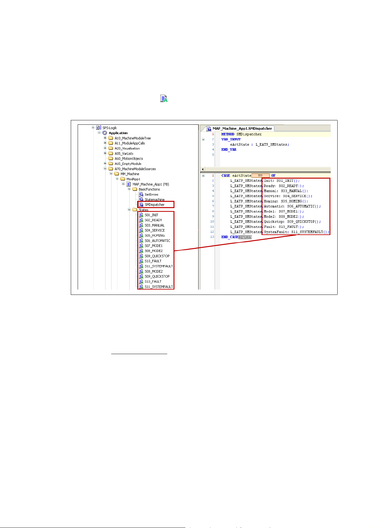
For easy structuring, Lenze recommend to use the Actions of the ApplicationTemplate.
•The Actions must be lower level to the module application.
• Actions are marked with the icon.
Example of structuring a module application:
[5-3] The SMDispatcher method calls the S01-S11 actions. The actions can be viewed in the ModApp1/Statesfolder.
An Action is always connected to a POU (example: function block of an MAP module application).
• Thereby the action only uses the data of function block. This means that the action does not
feature an own declaration part. The variables used in the action are declared in the function
block (i.e. in the MAP module application).
• The action does not feature any
local variables.
28
Lenze · ApplicationTemplate · 1.3 EN - 04/2013
Page 29
Overview - the structure of the ApplicationTemplate
_ _ _ _ _ _ _ _ _ _ _ _ _ _ _ _ _ _ _ _ _ _ _ _ _ _ _ _ _ _ _ _ _ _ _ _ _ _ _ _ _ _ _ _ _ _ _ _ _ _ _ _ _ _ _ _ _ _ _ _ _ _ _ _
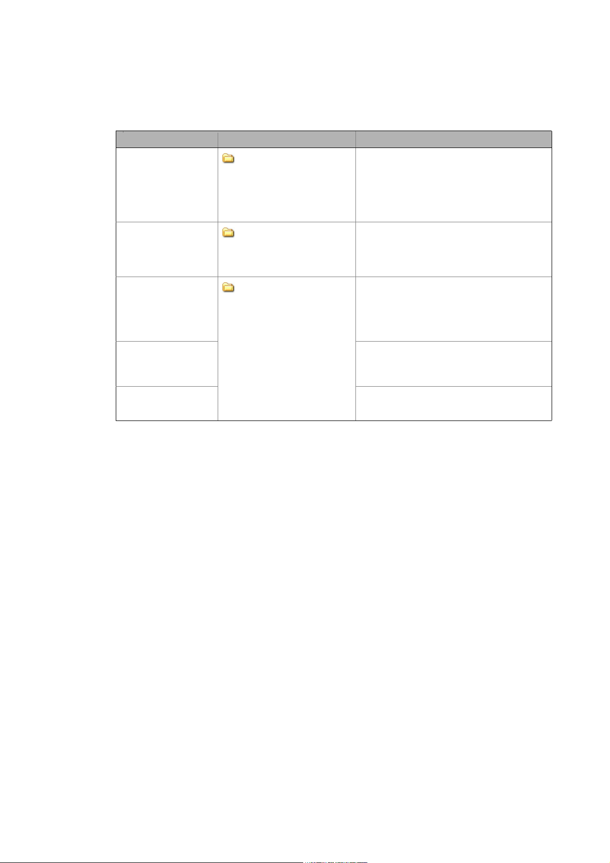
6 Overview - the structure of the ApplicationTemplate
The Lenze ApplicationTemplate facilitates programming with the »PLC Designer«.
• The ApplicationTemplateCounter has the following predefined structure:
A10_MachineModuleTree (MMT)
•The Machine module tree maps the mechatronic
functionality of the machine structure in the form of
machine modules (MM).
A11_ModuleAppCalls (MAC)
• ...contains the assignments of module applications (MAP)
to the tasks.
A20_Visualisation
• ...contains the visualizations for the device-independent
functions. Getting started - operating the
ApplicationTemplate ( 35)
A55_VarLists
• ...contains the declarations of the global variables:
• Machine modules used: MM_Dcl
•IO variables: MM_IO
• Parameters: MM_Par
• Variables for an external visualization: MM_Vis
• Persistent data: MM_PD
A60_MotionObjects
• ...predefined folder for motion-relevant data, example:
CAM profiles.
A65_EmptyModule
• ...contains the machine module sources
•...contains the EmptyModule template for creating your
own machine modules. Creating your own machine
modules: Copy/insertMM_EmptyModule ( 51)
A70_MachineModuleSources
• ...contains the individually created machine
modulesMachine modules (MM)
• ...contains the visualization of the machine modules.
ApplicationTemplateCounter:
• ...contains two predefined machine modules.
A71_LocalSources
• ...storage location for machine-independent
enumerations, function blocks, structures, visualizations.
A80_Documentation
• ...predefined folders for "project history" documents,
example: version information, changes.
A90_Resources
• ...contains the system information such as:
•Task settings,
• Libraries used,
• Recipe manager,
•Visualization manager.
( 18)
Tip!
Combine the "local sources" from the A71_LocalSources folder in one library.
Lenze · ApplicationTemplate · 1.3 EN - 04/2013 29
Page 30

Opening the ApplicationTemplate
_ _ _ _ _ _ _ _ _ _ _ _ _ _ _ _ _ _ _ _ _ _ _ _ _ _ _ _ _ _ _ _ _ _ _ _ _ _ _ _ _ _ _ _ _ _ _ _ _ _ _ _ _ _ _ _ _ _ _ _ _ _ _ _
7 Opening the ApplicationTemplate
The ApplicationTemplateCounter includes a sample program with three machine modules and a
predefined visualization. The sample program serves to test the basic functions of the
ApplicationTemplate. The sample program in the ApplicationTemplateCounter
Standard procedure
The main steps are summarised in the following table:
Step Action
1. Create a new project - open the ApplicationTemplate
2. Update the controller in the project (optional)
3. Going online
• Compiling the project data
• Transferring the project to the control - "Log in"
4. Loading and starting the PLC program
5. Getting started - operating the ApplicationTemplate
( 33)
( 33)
( 33)
( 31)
( 32)
( 33)
( 35)
( 134)
Further information on the parameter setting and configuration of the respective bus
system can be found in the following communication manuals (KHB):
• Communication manual EtherCAT: "Controller-based Automation" EtherCAT
• Communication manual CANopen: "Controller-based Automation" CANopen
Detailed commissioning steps
The following section describes the individual commissioning steps in detail.
Follow the instructions specified step by step to commission your automation system.
• Communication manual PROFIBUS: "Controller-based Automation" PROFIBUS
30 Lenze · ApplicationTemplate · 1.3 EN - 04/2013
Page 31

Opening the ApplicationTemplate
Create a new project - open the ApplicationTemplate
_ _ _ _ _ _ _ _ _ _ _ _ _ _ _ _ _ _ _ _ _ _ _ _ _ _ _ _ _ _ _ _ _ _ _ _ _ _ _ _ _ _ _ _ _ _ _ _ _ _ _ _ _ _ _ _ _ _ _ _ _ _ _ _
7.1 Create a new project - open the ApplicationTemplate
The ApplicationTemplate is included as a project template (*.project, ) im »PLC Designer« from
V3.3 onwards. In order to call the ApplicationTemplate, a new project has to be created, taking the
ApplicationTemplate as template.
How to proceed:
1. Create new project:
• File New project
•Select category Lenze Application Template
• Open template L_ApplicationTemplate
Which template do you want to use? Function
ApplicationTemplate Use Lenze application template L_ApplicationTemplate.
It includes a structure predefined by Lenze which serves to ...
• ... standardise applications by means of a defined folder structure.
• ... structure applications with machine modules.
ApplicationTemplateCounter Sample project with the Lenze application template L_ApplicationTemplate.
• It includes two lower-level machine modules which are integrated into
the MachineModuleTree (MMT).
• Contains one counter example (Automatic Modus).
The sample project is located in the Lenze Application Samples\Lenze
Standard category
Lenze · ApplicationTemplate · 1.3 EN - 04/2013 31
Page 32

Opening the ApplicationTemplate
Update the controller in the project (optional)
_ _ _ _ _ _ _ _ _ _ _ _ _ _ _ _ _ _ _ _ _ _ _ _ _ _ _ _ _ _ _ _ _ _ _ _ _ _ _ _ _ _ _ _ _ _ _ _ _ _ _ _ _ _ _ _ _ _ _ _ _ _ _ _
7.2 Update the controller in the project (optional)
Cases in which the project must be updated
The controller in the »PLC Designer« must be updated if ...
• ...the project contains firmware information that is older than the hardware to be used or
• ...a controller other than the integrated 3200 C controller is desired (example: p500).
If the controller is marked with the icon after the project is opened, the device information of
the »PLC Designer« project have to be updated.
Determining the firmware of the controller
How to proceed:
• Use the »WebConfig« to check which firmware is used by the controller to select the
appropriate device information in the »PLC Designer«.
• If the controller must be updated, the dynamic memory settings of the application must be
adapted.
Adapting the memory settings
Highlight the desired controller.
• Execute the Update device command in the context menu.
• Double-click the applicable controller in the Update device dialog window to update the
controller in the Device view:
1. In the context menu of Application, execute the Properties command.
•On the Application build options tab, activate the; Use dynamic memory allocation
option.
•For Maximum size of memory, enter a value of 100000:
•Click OK to confirm.
32
Lenze · ApplicationTemplate · 1.3 EN - 04/2013
Page 33

Opening the ApplicationTemplate
Going online
_ _ _ _ _ _ _ _ _ _ _ _ _ _ _ _ _ _ _ _ _ _ _ _ _ _ _ _ _ _ _ _ _ _ _ _ _ _ _ _ _ _ _ _ _ _ _ _ _ _ _ _ _ _ _ _ _ _ _ _ _ _ _ _
7.3 Going online
In order to be able to establish an online connection to the controller, the communication settings
(Set active path) must be commissioned before. Establishing communication with the controller
( 13)
7.3.1 Compiling the project data
To compile the project data, select the BuildBuild menu command or press the <F11> function
key.
• If errors occur during the compilation, they are to be localised on the basis of the »PLC Designer«
error messages and corrected correspondingly. Recompile the project data afterwards.
• If no errors occur during the compilation, the »PLC Designer« project must be saved:
File Save project
7.3.2 Transferring the project to the control - "Log in"
Note!
To "log in" the PLC program must be error-free. For this it must be possible to execute the
BuildBuild (F11) menu command without an error message.
The desired project must be transferred to the PLC device by "Logging in" to the controller: Call menu
command Online Log in.
7.4 Loading and starting the PLC program
• Load the PLC program to the controller: Call OnlineLoad menu command.
• Start the PLC program: Call OnlineStart menu command.
• As an alternative, you can execute the DebugStart menu command or press <F5>.
Tip!
In order to load a project automatically after a device is restarted, it can be defined as
"boot project".
Setting up the project as boot application
How to install the project as boot project:
1. Select the OnlineGenerate boot project for L-force Controller menu command.
Lenze · ApplicationTemplate · 1.3 EN - 04/2013 33
Page 34

Opening the ApplicationTemplate
Simulation (valid for the ApplicationTemplateCounter)
_ _ _ _ _ _ _ _ _ _ _ _ _ _ _ _ _ _ _ _ _ _ _ _ _ _ _ _ _ _ _ _ _ _ _ _ _ _ _ _ _ _ _ _ _ _ _ _ _ _ _ _ _ _ _ _ _ _ _ _ _ _ _ _
7.5 Simulation (valid for the ApplicationTemplateCounter)
Note!
In order to be able to use the simulation mode in the "ApplicationTemplateCounter", the
"Watchdog" monitoring must be deactivated (corresponds to the standard setting in the
ApplicationTemplate).
An activated "Watchdog" monitoring results in an error message so that the simulation
mode cannot be activated.
How to deactivate the "Watchdog" monitoring:
1. Double-click the A90_Resources folder in the device view.
• Double-click Task configuration TaskHighPriority .
•On the Configuration tab, deactivate the Watchdog option by removing the ;
checkmark:
•Double-click Task configuration TaskMidPriority .
•On the Configuration tab, deactivate the Watchdog option by removing the ;
checkmark:
34
Lenze · ApplicationTemplate · 1.3 EN - 04/2013
Page 35

Opening the ApplicationTemplate
Getting started - operating the ApplicationTemplate
_ _ _ _ _ _ _ _ _ _ _ _ _ _ _ _ _ _ _ _ _ _ _ _ _ _ _ _ _ _ _ _ _ _ _ _ _ _ _ _ _ _ _ _ _ _ _ _ _ _ _ _ _ _ _ _ _ _ _ _ _ _ _ _
7.6 Getting started - operating the ApplicationTemplate
In the Device view, select the A20_Visualisation folder: Double-click the L_Main visualization.
Welcome page - L_Main visualization
The user interface of the visualization is divided into the following areas:
[7-1] Example: ApplicationTemplateCounter with two machine modules (module 1, module 2)
Select machine module Error block visualization
Detailed view of the machine modules ApplicationTemplate visualization
Select error overview Buttons: Select status/acknowledge error message
State machine
Lenze · ApplicationTemplate · 1.3 EN - 04/2013 35
Page 36

Opening the ApplicationTemplate
Getting started - operating the ApplicationTemplate
_ _ _ _ _ _ _ _ _ _ _ _ _ _ _ _ _ _ _ _ _ _ _ _ _ _ _ _ _ _ _ _ _ _ _ _ _ _ _ _ _ _ _ _ _ _ _ _ _ _ _ _ _ _ _ _ _ _ _ _ _ _ _ _
• The buttons in area can be used to select the
visualization of the desired machine module.
• Machine / machine control calls the highest machine
control module.
• Button calls the detailed view of the machine
modules.
• Button calls the global error overview.
•Area displays the state machine (with the current status).
State machine ( 21)
•Area displays the L_EATP_ErrorSet FB. L_EATP_ErrorSet ( 119)
36
Lenze · ApplicationTemplate · 1.3 EN - 04/2013
Page 37

Opening the ApplicationTemplate
Visualisation of the machine modules
_ _ _ _ _ _ _ _ _ _ _ _ _ _ _ _ _ _ _ _ _ _ _ _ _ _ _ _ _ _ _ _ _ _ _ _ _ _ _ _ _ _ _ _ _ _ _ _ _ _ _ _ _ _ _ _ _ _ _ _ _ _ _ _
•Area visualises communication between the
individual machine modules by the AppChannelData
structure.
• The AppChannelData structure provides the
infrastructure for communication of the application
data. The AppChannelData structure(ACD)
• ApplicationTemplateCounter:
In this area, the demo visualization of the sample
programs is shown. The sample program in the
ApplicationTemplateCounter ( 134)
•The Lock data button inhibits a data area of the ACD
structure/enables the data area again.
Methods for inhibit/enable
• Lock(): Inhibit data area of the ACD structure.
L_EATP_CriticalSection
• Unlock(): Enable inhibited data area of the ACD
structure.
L_EATP_ErrorListHandler
•
Consistent data transfer
( 117)
( 118)
( 99)
( 73)
7.7 Visualisation of the machine modules
• The buttons in area activate the desired status
(state)/enable the acknowledgement of errors.
•The Error Quit button acknowledges the error
message. Error handling
•If e.g. MM_Modul 1 is selected, errors can
be triggered via fields xError[01...04] of
L_EATP_ErrorSet .
L_EATP_ErrorSet
( 92)
( 119)
Lenze · ApplicationTemplate · 1.3 EN - 04/2013 37
Page 38

Opening the ApplicationTemplate
Visualisation of the machine modules
_ _ _ _ _ _ _ _ _ _ _ _ _ _ _ _ _ _ _ _ _ _ _ _ _ _ _ _ _ _ _ _ _ _ _ _ _ _ _ _ _ _ _ _ _ _ _ _ _ _ _ _ _ _ _ _ _ _ _ _ _ _ _ _
• Depending on the standard response,
triggering an error at L_EATP_ErrorSet
results in a state change in area
• Possible error responses are: Error,
SystemFault, Warning, Information.
• Default setting of the
ApplicationTemplate (can be deactivated,
if required):
When an error is triggered, the higher-level
machine module changes to the "Quick
stop" state.
• The machine module forwards the state
to the higher-level machine module.
• The machine module on the top level
sets all lower-level machine modules to
the "Quick stop" status.
.
•The Module List button calls the detailed
view for the machine modules.
• Click the desired machine module to show
the respective status and further details.
•The Error List button calls the global error
list which provides an overview of the
errors that have occurred.
• The cause of the fault activation must
be eliminated. Then the corresponding
error must be reset.
• To reset the error, the Error Quit button
is to be pressed.
38
Lenze · ApplicationTemplate · 1.3 EN - 04/2013
Page 39

Working with the ApplicationTemplate
_ _ _ _ _ _ _ _ _ _ _ _ _ _ _ _ _ _ _ _ _ _ _ _ _ _ _ _ _ _ _ _ _ _ _ _ _ _ _ _ _ _ _ _ _ _ _ _ _ _ _ _ _ _ _ _ _ _ _ _ _ _ _ _
8 Working with the ApplicationTemplate
This chapter provides information on how to create modular machine functions / machine modules
with the machine module template in the ApplicationTemplate. The MM_EmptyModule machine
module is a template for the creation of individual machine modules.
Programming with the ApplicationTemplate: What has to be done?
Step Action Detailed information
1. Structuring the automation system
• The overall functionality (machine
application) of the automation system is to
be mapped modularly:
One subfunction = one machine module
• In this project phase, programming is not
yet required!
2. Starting the ApplicationTemplate Opening the ApplicationTemplate
3. Updating the project (optional)
• Adjust the device information version in the
»PLC Designer« project to the firmware
version of the controller.
• Integrate another controller in the project if
required. The controller included is the
3200 C.
4. Mapping the actual machine structure in the
»PLC Designer«
Assign the relative address to the machine modules.
( 25)
Update the controller in the project (optional)
Mapping the actual machine structure in the »PLC
Designer« ( 40)
( 30)
( 32)
• Adding devices - EtherCAT bus system
• Adding devices - CANopen bus system (optional)
( 43)
• Setting of CAN parameters and PDO mapping
6. Creating/integrating individual machine
modules
7. Integrating devices Inserting an axis
8. Going online Going online ( 33)
9. Starting the PLC program Loading and starting the PLC program
Carrying out an online change Online change
Creating your own machine modules: Copy/
insertMM_EmptyModule ( 51)
( 58)
Integrating I/O modules of the I/O system 1000 with a
machine module ( 60)
Integrating a module application
( 68)
( 66)
( 40)
( 33)
( 48)
Lenze · ApplicationTemplate · 1.3 EN - 04/2013 39
Page 40

Working with the ApplicationTemplate
Mapping the actual machine structure in the »PLC Designer«
_ _ _ _ _ _ _ _ _ _ _ _ _ _ _ _ _ _ _ _ _ _ _ _ _ _ _ _ _ _ _ _ _ _ _ _ _ _ _ _ _ _ _ _ _ _ _ _ _ _ _ _ _ _ _ _ _ _ _ _ _ _ _ _
8.1 Mapping the actual machine structure in the »PLC Designer«
The ApplicationTemplate contains a predefined structure that can be extended by the individual
requirements. Carry out the following steps to map the actual machine structure.
8.1.1 Adding devices - EtherCAT bus system
Note!
The following points have to be observed before starting to set up an EtherCAT
configuration in the »PLC Designer«:
• The sequence of the EtherCAT slaves in the device view must correspond to the
physical arrangement of the EtherCAT topology.
• Select the cycle times according to the technical data, from 1 ... 10 ms.
How to create the control configuration in the »PLC Designer«:
1. Go to the context menu of the target system and use the Add Device command to
extend the control configuration by "EtherCAT master".
40
Lenze · ApplicationTemplate · 1.3 EN - 04/2013
Page 41

Working with the ApplicationTemplate
Mapping the actual machine structure in the »PLC Designer«
_ _ _ _ _ _ _ _ _ _ _ _ _ _ _ _ _ _ _ _ _ _ _ _ _ _ _ _ _ _ _ _ _ _ _ _ _ _ _ _ _ _ _ _ _ _ _ _ _ _ _ _ _ _ _ _ _ _ _ _ _ _ _ _
2. Add an EtherCAT slave below the EtherCAT Master: Right-click the EtherCAT Master
Add device:
Select the desired device from the selection list .
The »PLC Designer« provides a "fieldbus scan" during which the devices connected to the
fieldbus are automatically detected.
Further information is provided in the "Controller-based Automation EtherCAT" section of
the online help for the »PLC Designer« and in the Controller-based Automation EtherCAT
communication manual (KHB).
Repeat the Add device until all slaves connected to the fieldbus are implemented in the
device view.
Lenze · ApplicationTemplate · 1.3 EN - 04/2013 41
Page 42

Working with the ApplicationTemplate
Mapping the actual machine structure in the »PLC Designer«
_ _ _ _ _ _ _ _ _ _ _ _ _ _ _ _ _ _ _ _ _ _ _ _ _ _ _ _ _ _ _ _ _ _ _ _ _ _ _ _ _ _ _ _ _ _ _ _ _ _ _ _ _ _ _ _ _ _ _ _ _ _ _ _
3. Allocate unique designations to the slaves inserted
(example: "L_94_HL_ActuatorSpeed").
The names can be selected freely and must …
•only
contain the characters "A ... Z", "a ... z", "0 ... 9", or "_";
•not
start with a digit.
You can enter a name by clicking the element.
Example:
4. Setting the cycle time
• The value for the EtherCAT master cycle time has to be defined according to the cycle
time of the quickest task.
• The icon in front of the respective device indicates the successful
EtherCAT communication.
Note: The EtherCAT cycle time is to be set to the quickest task cycle time set. In this
ApplicationTemplate, the quickest task cycle time is set to 2 ms, therefore 2000 μs have to
be set here.
42
Lenze · ApplicationTemplate · 1.3 EN - 04/2013
Page 43

Working with the ApplicationTemplate
Mapping the actual machine structure in the »PLC Designer«
_ _ _ _ _ _ _ _ _ _ _ _ _ _ _ _ _ _ _ _ _ _ _ _ _ _ _ _ _ _ _ _ _ _ _ _ _ _ _ _ _ _ _ _ _ _ _ _ _ _ _ _ _ _ _ _ _ _ _ _ _ _ _ _
• If the "Distributed Clocks" option is activated for all controllers and communication is
successful, the EtherCAT Master provides the "DC In-Sync" message:
8.1.2 Adding devices - CANopen bus system (optional)
In order to map the desired machine structure on the basis of the ApplicationTemplate, the
corresponding devices have to be added in the Device view.
How to proceed:
1. Select the controller
• In the context menu, execute the Add device command to add "CANbus" to the bus
system .
Lenze · ApplicationTemplate · 1.3 EN - 04/2013 43
Page 44

Working with the ApplicationTemplate
Mapping the actual machine structure in the »PLC Designer«
_ _ _ _ _ _ _ _ _ _ _ _ _ _ _ _ _ _ _ _ _ _ _ _ _ _ _ _ _ _ _ _ _ _ _ _ _ _ _ _ _ _ _ _ _ _ _ _ _ _ _ _ _ _ _ _ _ _ _ _ _ _ _ _
2. Set the baud rate via the CANbus tab.
Note: The value of the transfer rate set in the »PLC Designer« overwrites any existing
transfer values of the devices (set via »WebConfig«/»Engineer«).
3. In a CANopen network, set the same baud rate for all nodes.
4. Use the Add Device command to extend the control configuration by "CANopen
Manager".
44
Lenze · ApplicationTemplate · 1.3 EN - 04/2013
Page 45

Working with the ApplicationTemplate
Mapping the actual machine structure in the »PLC Designer«
_ _ _ _ _ _ _ _ _ _ _ _ _ _ _ _ _ _ _ _ _ _ _ _ _ _ _ _ _ _ _ _ _ _ _ _ _ _ _ _ _ _ _ _ _ _ _ _ _ _ _ _ _ _ _ _ _ _ _ _ _ _ _ _
5. Go to the CANopen_Manager tab to set the parameters for sync generation.
The sync producing is required if ...
• ...at least one PDO with sync-controlled processing is used on the bus;
• ...the applications are to run synchronously in several devices;
• ...motion devices are to be connected to the bus.
If you want to use CAN synchronisation, check the EnableSync Producing input field.
Set Sync cycle time: 2 ms (input value: 2000 μs)
• The value for the CANopen master cycle time has to be defined according to the cycle
time of the quickest task.
Lenze · ApplicationTemplate · 1.3 EN - 04/2013 45
Page 46

Working with the ApplicationTemplate
Mapping the actual machine structure in the »PLC Designer«
_ _ _ _ _ _ _ _ _ _ _ _ _ _ _ _ _ _ _ _ _ _ _ _ _ _ _ _ _ _ _ _ _ _ _ _ _ _ _ _ _ _ _ _ _ _ _ _ _ _ _ _ _ _ _ _ _ _ _ _ _ _ _ _
6. Use the Add Device command to insert a logic device (slave) under the
CANopen_Manager (master).
Select the desired CAN node from the selection list.
Tip!
A general device description is provided for the integration of inverters: Lenze Generic
Drive.
Repeat the Add device command until all slaves connected to the bus are implemented
in the device view. Optionally, you can Copy and Paste a node already inserted into the
context menu of the device. The communication settings (node ID and baud rate as well as
further parameters) must be adapted manually afterwards.
46
Lenze · ApplicationTemplate · 1.3 EN - 04/2013
Page 47

Working with the ApplicationTemplate
Mapping the actual machine structure in the »PLC Designer«
_ _ _ _ _ _ _ _ _ _ _ _ _ _ _ _ _ _ _ _ _ _ _ _ _ _ _ _ _ _ _ _ _ _ _ _ _ _ _ _ _ _ _ _ _ _ _ _ _ _ _ _ _ _ _ _ _ _ _ _ _ _ _ _
7. Allocate unique designations to the slaves inserted (example: "L_94_HL_ActuatorSpeed").
The names can be selected freely and must …
•only
contain the characters "A ... Z", "a ... z", "0 ... 9", or "_";
•not
start with a digit.
8. You can enter a name by clicking the element.
Example:
• Below the selected slave, the axis data are available in the form of an additional node.
In order to be able to link the process data
manually (instead of the automatic link to the
L_LCB_Axis_REF instance), the Manual I/O
mapping option has to be activated.
Lenze · ApplicationTemplate · 1.3 EN - 04/2013 47
Page 48

Working with the ApplicationTemplate
Mapping the actual machine structure in the »PLC Designer«
_ _ _ _ _ _ _ _ _ _ _ _ _ _ _ _ _ _ _ _ _ _ _ _ _ _ _ _ _ _ _ _ _ _ _ _ _ _ _ _ _ _ _ _ _ _ _ _ _ _ _ _ _ _ _ _ _ _ _ _ _ _ _ _
Setting of CAN parameters and PDO mapping
Set the CAN parameters and the PDO mapping for each Logic device connected to the bus.
How to set CAN parameters and CAN mapping:
1. Change to the CANopen Remote Device tab of the corresponding slave.
Assign the suitable node addresses of the devices in the Node ID input field:
Only if the Expert settings option is set, the following settings are possible and visible:
• "Node Guarding"
•"Emergency"
•"Heartbeat"
• "Checks at Startup"
Make the settings required for your application here.
48
Lenze · ApplicationTemplate · 1.3 EN - 04/2013
Page 49

Working with the ApplicationTemplate
Mapping the actual machine structure in the »PLC Designer«
_ _ _ _ _ _ _ _ _ _ _ _ _ _ _ _ _ _ _ _ _ _ _ _ _ _ _ _ _ _ _ _ _ _ _ _ _ _ _ _ _ _ _ _ _ _ _ _ _ _ _ _ _ _ _ _ _ _ _ _ _ _ _ _
2. Change to the PDO Mapping tab.
By default, the PDO mapping is optimised for the corresponding application. It is possible
to change this mapping (set checkmark ). Du e to the limited bandwidth of the CAN bus, this
is only sensible in special cases. The PDO properties are pre-assigned sensibly as well and
should not be changed.
By double-clicking a single PDO, you can see its transmission properties.
•The Transmission Type "cyclic - synchronous (type 1-240)" and the information
at which sync the PDOs are to be transmitted must not be changed.
• The settings of the Inhibit time and the Event time are not evaluated.
• Confirm the settings with OK.
The CANopen I/O Mapping tab serves to assign PLC variables to the process image.
Note!
Bus operation without CAN synchronisation
• The controller always transmits asynchronous PDOs from an unsolicited task in an
event-controlled way. To achieve a time-controlled transmission of asynchronous
PDOs by the controller, you must assign the CAN master to a cyclic task.
• The controller does not support any monitoring times for asynchronous receipt PDOs.
These monitoring times have to be set in the devices.
Lenze · ApplicationTemplate · 1.3 EN - 04/2013 49
Page 50

Working with the ApplicationTemplate
Mapping the actual machine structure in the »PLC Designer«
_ _ _ _ _ _ _ _ _ _ _ _ _ _ _ _ _ _ _ _ _ _ _ _ _ _ _ _ _ _ _ _ _ _ _ _ _ _ _ _ _ _ _ _ _ _ _ _ _ _ _ _ _ _ _ _ _ _ _ _ _ _ _ _
3. The selection of a special bus cycle task on the CANopen I/O image of the CANopen
manager is not mandatory.
The standard setting uses the task with the shortest cycle time that accesses the devices of
the CAN master as bus cycle task:
50
Lenze · ApplicationTemplate · 1.3 EN - 04/2013
Page 51

Working with the ApplicationTemplate
Creating your own machine modules: Copy/insertMM_EmptyModule
_ _ _ _ _ _ _ _ _ _ _ _ _ _ _ _ _ _ _ _ _ _ _ _ _ _ _ _ _ _ _ _ _ _ _ _ _ _ _ _ _ _ _ _ _ _ _ _ _ _ _ _ _ _ _ _ _ _ _ _ _ _ _ _
8.2 Creating your own machine modules: Copy/insertMM_EmptyModule
Tip!
If individual machine modules are created, the ApplicationTemplate automatically assigns
the corresponding machine module-internal names.
Creating machine modules: What has to be done?
The EmptyModule machine module template...
• ...has to be copied in the A65 EmptyModule folder
using the Copy Empty Module command and
• ...then using the Insert Empty Module command to
insert it into the A70_MachineModuleSources
folder.
In most cases (due to the individual requirements), you have
to create the (MM_Machine) machine control module
yourself.
How to proceed:
1. Copy the MM_EmptyModule machine module:
•Right-click the A65 EmptyModule\MM_EmptyModule folder
Empty Module.
2. Insert the previously copied machine module (Empty Module) below the
A70_MachineModuleSources folder:
•Right-click the A70_MachineModuleSources
Insert Empty Module
Select Copy
Lenze · ApplicationTemplate · 1.3 EN - 04/2013 51
Page 52

Working with the ApplicationTemplate
Creating your own machine modules: Copy/insertMM_EmptyModule
_ _ _ _ _ _ _ _ _ _ _ _ _ _ _ _ _ _ _ _ _ _ _ _ _ _ _ _ _ _ _ _ _ _ _ _ _ _ _ _ _ _ _ _ _ _ _ _ _ _ _ _ _ _ _ _ _ _ _ _ _ _ _ _
3. Enter the desired module name.
The module name can be selected freely and …
• must not
•may only
• must not
4. Click Insert to insert the machine module.
• The machine module has been inserted with the applicable names of the MAPs/MFB,
structures, and visualization.
5. The machine module inserted (MFB_*) is to be inserted in the MMT in the
A10_MachineModuleTree folder.
6. The module application (MAP_*) in the A11_ModuleAppCalls folder is to be inserted in
the desired module application call (MAC_Task_*).
contain "MM_"
contain the characters "A ... Z", "a ... z", "0 ... 9"
contain any special characters.
52
Lenze · ApplicationTemplate · 1.3 EN - 04/2013
Page 53

Working with the ApplicationTemplate
Integrating a machine module into the MMT
_ _ _ _ _ _ _ _ _ _ _ _ _ _ _ _ _ _ _ _ _ _ _ _ _ _ _ _ _ _ _ _ _ _ _ _ _ _ _ _ _ _ _ _ _ _ _ _ _ _ _ _ _ _ _ _ _ _ _ _ _ _ _ _
8.3 Integrating a machine module into the MMT
The machine module (created on the basis of the MM_EmptyModule template) has to be integrated
into the MachineModuleTree(MMT) to implement it in the ApplicationTemplate in a serviceable
state.
How to proceed:
1. Double-click the A10_MachineModuleTree folder in the device view.
• Double-click MMT (PRG).
Note: The programming language of MMT (PRG) is CFC (Continuous Function Chart).
•In the Tools dialog window, click the Block button.
• Create the new FB via drag-and-drop.
• Double-click the area of the FB. Click the button.
Use the Input assistance from the Application element...
• ...to assign the MFB_CrossCutter FB.
• ...to assign the CrossCutter instance.
Note: Go to the Input assistant and select the ; Insert with namespace prefix when
assigning the instance name.
2. Specify the relative address for the machine module.
•In the Tools dialog window, click the Input button.
• Add the new input at MM_Address
• Assign the relative address (example: 3).
3. Connect FBs MFB_MachineControl and MFB_CrossCutter to each other.
• Example (ApplicationTemplate Counter):
Note: After inserting a machine module, the processing order
which results after inserting the further machine module is to be checked.
For changing the Processing order
the corresponding machine module.
• For this, call the Processing order menu item in the context menu of the element
Lenze · ApplicationTemplate · 1.3 EN - 04/2013 53
, adapt the element number in the top right corner of
of the machine modules
Page 54

Working with the ApplicationTemplate
Assigning the module application (MAP) to the task
_ _ _ _ _ _ _ _ _ _ _ _ _ _ _ _ _ _ _ _ _ _ _ _ _ _ _ _ _ _ _ _ _ _ _ _ _ _ _ _ _ _ _ _ _ _ _ _ _ _ _ _ _ _ _ _ _ _ _ _ _ _ _ _
number (right mouse button).
Note: If the "Structured view" option is deactivated, an FB (example: MFB_CrossCutter) can
be reached via the input assistance (category: Instances).
8.4 Assigning the module application (MAP) to the task
For machine modules that have been created using the EmptyModule template, the MAP and task
can be easily assigned via a dialog window.
Tip!
For creating machine modules, use the EmptyModule template in the
A65_EmptyModule folder to assign the module applications to the tasks easier.
How to proceed:
1. Right-click the A11_ModuleAppCalls folder:
•Call Create Task Call.
2. Go to the following dialog window and mark the module application in the area
(example: MM_NewModule) and in area , mark the task to be assigned to the MAP.
• Assign/unassign the task to the respective MAP using <</>>.
[8-1] Example: ModuleApp1 is assigned to the task with the highest priority Task_High.
•Confirm assignment by clicking OK.
54
Lenze · ApplicationTemplate · 1.3 EN - 04/2013
Page 55

Working with the ApplicationTemplate
Assigning the module application (MAP) to the task
_ _ _ _ _ _ _ _ _ _ _ _ _ _ _ _ _ _ _ _ _ _ _ _ _ _ _ _ _ _ _ _ _ _ _ _ _ _ _ _ _ _ _ _ _ _ _ _ _ _ _ _ _ _ _ _ _ _ _ _ _ _ _ _
Manual assignment
How to proceed:
1. Double-click the A11_ModuleAppCalls folder.
2. Add the module application call in the program part of the corresponding task (example:
MAC_Task_high).
Note: The programming language of MAC_Task_xxx (PRG) is FBD (function block diagram).
•Use the Input assistance to assign the structure MM_Par.sc<module name> (element:
Application).
Note: Activate the Insert with namespace prefix option in the ;Input assistant .
Results: The machine module...
• ...is now integrated into the machine module tree (MMT).
• ...can be controlled by the internal state machine.
Lenze · ApplicationTemplate · 1.3 EN - 04/2013 55
Page 56

Working with the ApplicationTemplate
Remove the instances of a machine module
_ _ _ _ _ _ _ _ _ _ _ _ _ _ _ _ _ _ _ _ _ _ _ _ _ _ _ _ _ _ _ _ _ _ _ _ _ _ _ _ _ _ _ _ _ _ _ _ _ _ _ _ _ _ _ _ _ _ _ _ _ _ _ _
8.5 Remove the instances of a machine module
The previously inserted instances of a machine module have to be removed from the global variable
lists in the A55_VarLists folder.
How to proceed:
1. Double-click the A55_VarLists folder.
2. Double-click the global MM_Dcl variable list.
3. Right-click the instance to be deleted (example: NewModule):
8.6 Removing machine modules
In order to remove a machine module including all instances from the »PLC Designer« project,
execute the Delete command.
How to proceed:
Right-click the module name in the A70_MachineModuleSources folder and execute
the Delete command.
8.7 Module ID
• Each machine module can be identified by a unique module ID
which is stored in every MFB of the machine module in each
case.
• The module ID is defined with the name CompID in the
BaseChannel and can be set by the setCompIDAndVersion()
method.
[8-2] Example: Structured overview of the components of an MFB_MachineControl of the MM_Machine machine module
56
Lenze · ApplicationTemplate · 1.3 EN - 04/2013
Page 57

Working with the ApplicationTemplate
Module ID
_ _ _ _ _ _ _ _ _ _ _ _ _ _ _ _ _ _ _ _ _ _ _ _ _ _ _ _ _ _ _ _ _ _ _ _ _ _ _ _ _ _ _ _ _ _ _ _ _ _ _ _ _ _ _ _ _ _ _ _ _ _ _ _
• The respective module ID (CompID) can be viewed in the visualization under Machine Module
Details:Folder A20_Visualisation L_Main, Module List button.
Tip!
Allocate a suitable module ID CompID for every newly created machine module.
When revising a module, update the Version accordingly.
Lenze · ApplicationTemplate · 1.3 EN - 04/2013 57
Page 58

Working with the ApplicationTemplate
Inserting an axis
_ _ _ _ _ _ _ _ _ _ _ _ _ _ _ _ _ _ _ _ _ _ _ _ _ _ _ _ _ _ _ _ _ _ _ _ _ _ _ _ _ _ _ _ _ _ _ _ _ _ _ _ _ _ _ _ _ _ _ _ _ _ _ _
8.8 Inserting an axis
In order to connect an axis to a machine module, the following has to be observed when creating a
machine module.
• The following example shows how an axis is to be connected to the MM_Module2 machine
module.
• The axis is to be connected to the task with the highest priority MAC_Task_High.
How to proceed:
1. Call the module application within which an axis is to be connected:
• Extend the module application by the declaration: AXIS: AXIS_REF_SM3
2. In the A11_ModuleAppCalls folder, update the task into which the module application
is integrated: MAC_Task_High
• Delete the present module name (here: MAP2_Modul2_App1) in the FB of the module
application:
3. Assign the name of the module application (example: MAP_Module2_App1) to the FB:
58
Lenze · ApplicationTemplate · 1.3 EN - 04/2013
Page 59

Working with the ApplicationTemplate
Inserting an axis
_ _ _ _ _ _ _ _ _ _ _ _ _ _ _ _ _ _ _ _ _ _ _ _ _ _ _ _ _ _ _ _ _ _ _ _ _ _ _ _ _ _ _ _ _ _ _ _ _ _ _ _ _ _ _ _ _ _ _ _ _ _ _ _
4. Assign the name of the instance (example: MM_Dcl.Module2.App1) to the module
application:
5. Assign the axis to the module application. The precondition for this is that the actual
machine structure is mapped in the »PLC Designer« project. Mapping the actual machine
structure in the »PLC Designer« ( 40)
(The dwTestCounter input does not receive a transfer variable.)
• Select the desired axis (example: SM_Drive_ETC_9400HL)
•Click OK to insert the axis.
• The axis is connected to the machine module:
Lenze · ApplicationTemplate · 1.3 EN - 04/2013 59
Page 60

Working with the ApplicationTemplate
Integrating I/O modules of the I/O system 1000 with a machine module
_ _ _ _ _ _ _ _ _ _ _ _ _ _ _ _ _ _ _ _ _ _ _ _ _ _ _ _ _ _ _ _ _ _ _ _ _ _ _ _ _ _ _ _ _ _ _ _ _ _ _ _ _ _ _ _ _ _ _ _ _ _ _ _
8.9 Integrating I/O modules of the I/O system 1000 with a machine module
This chapter describes in which way the modules of an I/O system connected via CAN can be
accessed from a machine module.
Example: Access three digital inputs/outputs and one analog input /O system 1000 from the
MM_Module1 machine module.
How to proceed:
1. Right-click I_O_module_coupler
• Execute the Start Search menu command
The following dialog window shows all I/O modules identified.
•Click the Copy all device to project button to insert all devices found into the project.
60
Lenze · ApplicationTemplate · 1.3 EN - 04/2013
Page 61

Working with the ApplicationTemplate
Integrating I/O modules of the I/O system 1000 with a machine module
_ _ _ _ _ _ _ _ _ _ _ _ _ _ _ _ _ _ _ _ _ _ _ _ _ _ _ _ _ _ _ _ _ _ _ _ _ _ _ _ _ _ _ _ _ _ _ _ _ _ _ _ _ _ _ _ _ _ _ _ _ _ _ _
2. The variable names that are used in the machine module and that are connected to the I/
O system are summarised in the MM_IO structure.
3. Assign the variables to the physical I/O modules.
4. Activate the Always update variables option by ticking the checkbox (;):
Lenze · ApplicationTemplate · 1.3 EN - 04/2013 61
Page 62

Working with the ApplicationTemplate
Creating module applications
_ _ _ _ _ _ _ _ _ _ _ _ _ _ _ _ _ _ _ _ _ _ _ _ _ _ _ _ _ _ _ _ _ _ _ _ _ _ _ _ _ _ _ _ _ _ _ _ _ _ _ _ _ _ _ _ _ _ _ _ _ _ _ _
8.10 Creating module applications
This chapter describes how to create a module application.
Tip!
In the ApplicationTemplate, all positions that are to be edited if a new module application
is to be created are marked with the AT_ACTION_CREATE_NEW_MODULEAPPLICATION
keyword.
The search function in the »PLC Designer« makes it easier to find the positions to be edited:
• Execute the menu command EditFind&replaceFind
• Enter the required keyword and search/continue to search in order to navigate to the
corresponding positions in the ApplicationTemplate.
Example: Extend the MM_Module1 machine module by a module application.
• Initial situation:
• A machine module (example:
MM_Module1) is to be extended by a
module application.
• Create the module application in the
following folder of the machine module:
MM_Module1\ModApp1
How to create a module application:
1. Copy the MM_Module1\ModApp1 folder (right click: Copy) and insert it in the
MM_Module1 folder (right click: Paste).
Rename the following elements (by right click Properties):
•The folder name (previously: ModApp1): ModApp2
62
Lenze · ApplicationTemplate · 1.3 EN - 04/2013
Page 63

Working with the ApplicationTemplate
Creating module applications
_ _ _ _ _ _ _ _ _ _ _ _ _ _ _ _ _ _ _ _ _ _ _ _ _ _ _ _ _ _ _ _ _ _ _ _ _ _ _ _ _ _ _ _ _ _ _ _ _ _ _ _ _ _ _ _ _ _ _ _ _ _ _ _
• The FB name (previously: MAP_Module1_App1): MAP_Module1_App2
The module application has now been inserted.
The module application inserted is to be declared in the MFB_Module1 function block:
8.10.1 Adapting the function of the module application inserted - overview
Programming has to be adapted in the
following folders to achieve the desired
serviceability of the module application:
• Adapt the required parameters such as
error responses and error numbers.
•The SetErrors method in the
BasicFunctions folder is to be
adapted correspondingly if errors are to
be triggered from this module
application.
• If the state machine of this module
application is to work differently than
module application 1, the states are to be
programmed correspondingly.
Lenze · ApplicationTemplate · 1.3 EN - 04/2013 63
Page 64

Working with the ApplicationTemplate
Creating module applications
_ _ _ _ _ _ _ _ _ _ _ _ _ _ _ _ _ _ _ _ _ _ _ _ _ _ _ _ _ _ _ _ _ _ _ _ _ _ _ _ _ _ _ _ _ _ _ _ _ _ _ _ _ _ _ _ _ _ _ _ _ _ _ _
8.10.2 Frequently asked question: Connection between MFB and MAP
MFB_Module1 function block
The MachineModuleTree (MMT) maps the mechatronic structure of the automation system by
means of the MFB function blocks (MFB_Modulexx).
• Instancing of the MFB_Module1 must be executed in the MM_Dcl structure of the
A55_VarLists folder.
• Insert the instance in the desired position of the MMT.
[8-3] Example: Machine module tree in the ApplicationTemplateCounter
• A machine module encloses the module applications in the machine module.
• Therefore the module applications are to be declared within the machine module.
Instance the MAP_Module1_App1 module application with the following declaration line, so that
the instance can be called according to the task in the module application of ModuleAppCalls:
App1: MAP_Module1_App1 := (parentModule := THIS^);
•The parentModule:= THIS^ instruction connects the App1 module application to the basic
functions of all machine modules (e.g. state machine, error handling, BaseChannel). That way,
the App1 module application can access the basic functions of the ApplicationTemplate.
• Assign the ACD structure manually. The AppChannelData structure(ACD)
( 73)
[8-4] Example: App1
64
Lenze · ApplicationTemplate · 1.3 EN - 04/2013
Page 65

Working with the ApplicationTemplate
Creating module applications
_ _ _ _ _ _ _ _ _ _ _ _ _ _ _ _ _ _ _ _ _ _ _ _ _ _ _ _ _ _ _ _ _ _ _ _ _ _ _ _ _ _ _ _ _ _ _ _ _ _ _ _ _ _ _ _ _ _ _ _ _ _ _ _
Where do I find what in the
device view?
•MFB
[8-5] Linkage of machine module MFB, module structure tree (MMT), and task assignment of the module application (MAC)
Note!
A machine module must contain at least one module application which is assigned to a
ModulAppCall (and thus to a task)!
8.10.3 Programming with the module application
In order to structure the subfunction of a module application, the ApplicationTemplate actions are
to be used. Programming recommendations for structuring
Tip!
For programming with the ApplicationTemplate it is recommended to use the methods
included in the ApplicationTemplate.
State machine
Error handling ( 92)
The AppChannelData structure(ACD) ( 73)
( 77)
( 27)
Lenze · ApplicationTemplate · 1.3 EN - 04/2013 65
Page 66

Working with the ApplicationTemplate
Creating module applications
_ _ _ _ _ _ _ _ _ _ _ _ _ _ _ _ _ _ _ _ _ _ _ _ _ _ _ _ _ _ _ _ _ _ _ _ _ _ _ _ _ _ _ _ _ _ _ _ _ _ _ _ _ _ _ _ _ _ _ _ _ _ _ _
8.10.4 Integrating a module application
This section describes the procedure for integrating a newly created module application into a
machine module.
Tip!
In the ApplicationTemplate, all positions that are to be edited if a new module application
is to be integrated are marked with the AT_ACTION_ADD_MODULEAPPLICATION keyword.
The search function in the »PLC Designer« makes it easier to find the positions to be edited:
• Execute the menu command EditFind&replaceFind.
• Enter the required keyword and search/continue to search in order to navigate to the
corresponding positions in the ApplicationTemplate.
Example: Integration of the module application into the Task_Mid task.
How to integrate a module application:
Taking the MM_Module1 machine module as a basis, the example shows how the newly created
App2 module application is to be integrated into the ApplicationTemplate.
1. Call of the newly created module application in the corresponding task
( A11_ModuleAppCalls folder, MAC_Task_Mid block).
• Highlight the MAP_Module block.
• Copy and Paste the block (right click: Copy/ Paste)
66
Lenze · ApplicationTemplate · 1.3 EN - 04/2013
Page 67

Working with the ApplicationTemplate
Creating module applications
_ _ _ _ _ _ _ _ _ _ _ _ _ _ _ _ _ _ _ _ _ _ _ _ _ _ _ _ _ _ _ _ _ _ _ _ _ _ _ _ _ _ _ _ _ _ _ _ _ _ _ _ _ _ _ _ _ _ _ _ _ _ _ _
2. Integrate the new module application (MAP).
• Click the FB name
• Call the Input assistance by clicking the button.
•Use the Input assistance of the Application element to select the desired module
application which is to be integrated into the task.
Example: MAP_Module1_App2 module application
3. Click OK to integrate the module application.
4. Adapt the instance name correspondingly:
• Specify applicable instance name, i.e.: MM_Dcl.Module1.App2
Lenze · ApplicationTemplate · 1.3 EN - 04/2013 67
Page 68

Working with the ApplicationTemplate
Online change
_ _ _ _ _ _ _ _ _ _ _ _ _ _ _ _ _ _ _ _ _ _ _ _ _ _ _ _ _ _ _ _ _ _ _ _ _ _ _ _ _ _ _ _ _ _ _ _ _ _ _ _ _ _ _ _ _ _ _ _ _ _ _ _
Further information about extending the visualization can be found in the following section:
Extending the visualization
( 104)
8.11 Online change
"Online change" means only loading the changed program/data parts of a running application to
the controller.
• Thus no
• The "Online change" takes place after all tasks have been processed (task interval).
re-initialisation (warm restart, reset) takes place.
Note!
An "Online change" is only possible if a compiler listing is available. After the Clean all
and Clean application commands have been executed, an "Online change" is not
possible, since the cleaning process deletes all compile information (compiler listing).
8.11.1 When can an "Online change" be used in the ApplicationTemplate?
In the following application cases, an "Online change" can be executed without restrictions:
• Changes on the Program code and application data which have no
areas:
...the Machine Module Tree (MMT) structure
...the integration of machine module basic functions (for example the L_EATP_ErrorSet
function block for triggering errors).
• When the structure is changed and when machine module basic functions are integrated into
the ApplicationTemplate, an Online change is not to be used!
impact on the following
68
Lenze · ApplicationTemplate · 1.3 EN - 04/2013
Page 69

Working with the ApplicationTemplate
Online change
_ _ _ _ _ _ _ _ _ _ _ _ _ _ _ _ _ _ _ _ _ _ _ _ _ _ _ _ _ _ _ _ _ _ _ _ _ _ _ _ _ _ _ _ _ _ _ _ _ _ _ _ _ _ _ _ _ _ _ _ _ _ _ _
8.11.2 When is it not possible to use an "Online change" in the ApplicationTemplate?
Note!
Especially with regard to time-critical Motion applications, an Online change must only
be executed if all controllers with Motion function are at standstill.
If they are at standstill, a short-time interruption of the task timing (normally) does not
take effect.
In the following application cases, it is to be avoided that an "Online change" is executed:
• If the structure of the MMT is changed: e.g. when machine modules are added / removed.
• If the access to basic function blocks is changed: e.g. additional instances of the
L_EATP_ErrorSet function block for triggering errors.
Technical background information
A regeneration of the ApplicationTemplate structure (due to changes regarding the structure) is
only possible after a restart (at least warm restart). This requires a new Log in including a download.
• An "Online change" executes the changes on the application program during the "task interval"
(all tasks have completed their process).
• The exchange of the corresponding program blocks/data blocks by the runtime system causes
a time delay, so that negative effects on the task timing might occur.
Information regarding the time response
The following factors have the effect that the task process immediately after the online change
starts with a delay/is ineffective.
In the case of a high task utilisation (ratio of the task runtime and the task interval) and a resulting
short
task interval
and/or
the shifting of variables required for an Online change.
8.11.3 General programming recommendations which enable an "Online change"
The following factors must be observed during programming to enable an online change:
• Avoid pointers and references
Basically avoid the use of pointers and references. Then no special precautions have to be made for
an online change to ensure normal operation of the application.
• Avoid pointers and references in every clock cycle
If pointer and reference values have to be re-assigned in each clock cycle, it has to be ensured
that the referenced memory addresses have the correct value in the first clock cycle after an
online change.
Please note that, when assigning a reference or pointer value to another cycle, the source value
has to be updated in the clock cycle first, since otherwise the target of the assignment will show
the previous (old) value for at least one clock cycle.
• Use {attribute 'init_on_onlchange’ }
Lenze · ApplicationTemplate · 1.3 EN - 04/2013 69
Page 70

Working with the ApplicationTemplate
Online change
_ _ _ _ _ _ _ _ _ _ _ _ _ _ _ _ _ _ _ _ _ _ _ _ _ _ _ _ _ _ _ _ _ _ _ _ _ _ _ _ _ _ _ _ _ _ _ _ _ _ _ _ _ _ _ _ _ _ _ _ _ _ _ _
Reference or pointer variables (as well as other variables) provided with this attribute will be set
to their initial value after an online change.
• Thus the occurrence of an online change can be identified.
• Thus the initialisation processes can be executed again
completed).
• Use interface references
During an online change, interface references (interfaces) are automatically checked and adapted.
When interfaces and interface references are used for the ApplicationTemplate, please note that
the use is not required in a purely functional way and that it is only required for the purpose of the
online change.
In order to be able to access an FB instance, an additional method call of the interface (pointer/
reference to the FB instance) is required.
(after an online change has been
70
Lenze · ApplicationTemplate · 1.3 EN - 04/2013
Page 71

Architecture: The ApplicationTemplate in detail
Accessing structure variables of machine modules
_ _ _ _ _ _ _ _ _ _ _ _ _ _ _ _ _ _ _ _ _ _ _ _ _ _ _ _ _ _ _ _ _ _ _ _ _ _ _ _ _ _ _ _ _ _ _ _ _ _ _ _ _ _ _ _ _ _ _ _ _ _ _ _
9 Architecture: The ApplicationTemplate in detail
9.1 Accessing structure variables of machine modules
9.1.1 Accessing module's intrinsic structure variables
The structures of the machine modules contain the input and output variables of the machine
modules for integrating data in the complete system:
•I/O data: Structure MIO
• Parameters / data of the recipe manager: Structure MPar
• Persistent data: Structure MPD
• Visualization data: Structure MVis
Structures (Structs) for ...
...IOs
...parameters (recipe manager)
...persistent data
...external visualization
The following example shows how a structure variable for an external visualization (assigned to the
MAP) within a module application is to be called (when a module with automatically matching
names is assigned, the matching entries will be added automatically):
// MVis_scMachine
// for MAP1
diPieces : DINT;
// for MAP2
diLength : DINT;
[9-1] Extract from the MVIS_scMachine structure
VAR_IN_OUT
/// ------------------ START OF USER SPECIFIC BLOCK ---------------------
/// Add the needed declarations of Par, Vis, IO and PD access here
Par: MPar_scMachine;
Vis: MVis_scMachine;
IO: MIO_scMachine;
PD: MPD_scMachine;
/// ------------------- END OF USER SPECIFIC BLOCK ---------------------END_VAR
[9-2] Extract from the module application (MAP)
Lenze · ApplicationTemplate · 1.3 EN - 04/2013 71
Page 72

Architecture: The ApplicationTemplate in detail
Accessing structure variables of machine modules
_ _ _ _ _ _ _ _ _ _ _ _ _ _ _ _ _ _ _ _ _ _ _ _ _ _ _ _ _ _ _ _ _ _ _ _ _ _ _ _ _ _ _ _ _ _ _ _ _ _ _ _ _ _ _ _ _ _ _ _ _ _ _ _
The associated program call in the machine application has the following syntax:
Vis.diPieces := 4711;
[9-3] Sample program which assigns the value 4711 to the diPieces visualization variable.
9.1.2 Accessing structures of other machine modules
The global machine module structures are instanced in the A55_VarLists folder.
• Like this, the structures and machine modules of the ApplicationTemplate can be reused.
• The structure variables of an optional machine module can be used from another machine
module.
• In order to be able to use the variables of a global structure of machine module 1 (example:
MM_Module1) in another machine application of machine module 2 (example: MM_Module2),
the following program call is required:
diPiecesModul1 := MM_Vis.scModule1;
[9-4] Sample program: Accessing the MM_Vis structure of module 1.
72
Lenze · ApplicationTemplate · 1.3 EN - 04/2013
Page 73

Architecture: The ApplicationTemplate in detail
The AppChannelData structure(ACD)
_ _ _ _ _ _ _ _ _ _ _ _ _ _ _ _ _ _ _ _ _ _ _ _ _ _ _ _ _ _ _ _ _ _ _ _ _ _ _ _ _ _ _ _ _ _ _ _ _ _ _ _ _ _ _ _ _ _ _ _ _ _ _ _
9.2 The AppChannelData structure(ACD)
If required, the data structure of the MACD_sc type module name can be assigned within the desired
machine module (MFB).
The data structure must inherit the L_EATP_ACD_Base contained in the
L_EATP_ApplicationTemplate library. The L_EATP_ApplicationTemplate library
•The MACD_scModule1 structure defines the diCounter variable of the DINT data type.
[9-5] Configuration of the ACD structure with an inherited L_EATP_ACD_Base structure
•The MACD_sc<Module name> can be individually extended by the data types required.
• By the inherited structure, specific control and status bits are provided in the ACD structure.
( 110)
• In the structure, the L_EATP_CriticalSection block which ensures a consistent data exchange is
instanced (if the FB is used correctly).
More information about the L_EATP_ACD_Base structure: L_EATP_ACD_Base
9.2.1 Declaring/recording the ACD structure in the MFB
In order to be able to use the ACD structure in the module applications (MAPs) of an MFB and its
master, the instance of the ACD structure has to be declared locally in the MFB.
[9-6] Declaration of the ACD structure in the MFB_Module1
The ACD structure is recorded in the program part of the MFB; by this, safety mechanisms are
activated.
• The instance name and size of the structure are to be transferred to the RegisterACD() method.
• The structure is to be newly recorded during every cycle. (A missing recording triggers an
infrastructure error.)
( 127)
Lenze · ApplicationTemplate · 1.3 EN - 04/2013 73
Page 74

Architecture: The ApplicationTemplate in detail
The AppChannelData structure(ACD)
_ _ _ _ _ _ _ _ _ _ _ _ _ _ _ _ _ _ _ _ _ _ _ _ _ _ _ _ _ _ _ _ _ _ _ _ _ _ _ _ _ _ _ _ _ _ _ _ _ _ _ _ _ _ _ _ _ _ _ _ _ _ _ _
[9-7] Recorded ACD structure in the MFB_Module1
9.2.2 Accessing the ACD structure - by means of the MFB module application
[9-8] Schematic diagram: Accessing the ACD structure from the module application (MAP) of a machine module (MM_Module)
In order to access the ACD structure by means of the module application (MAP) of the MFB, ...
• ...a POINTER to the ACD structure and
• ...a reference to the ACD structure have to be declared in the desired module application.
[9-9] Declaration of the POINTER and REFERENCE to the ACD structure in the MAP of the MM_Module1 machine module
74
Lenze · ApplicationTemplate · 1.3 EN - 04/2013
Page 75

Architecture: The ApplicationTemplate in detail
The AppChannelData structure(ACD)
_ _ _ _ _ _ _ _ _ _ _ _ _ _ _ _ _ _ _ _ _ _ _ _ _ _ _ _ _ _ _ _ _ _ _ _ _ _ _ _ _ _ _ _ _ _ _ _ _ _ _ _ _ _ _ _ _ _ _ _ _ _ _ _
In the program part of the module application (MAP), access to the ACD structure by the
AccessACD() method is to be ensured:
[9-10] Program part of the MAP_Module1_App1 module application: Certify access to the ACD structure
This renders a read/write access by means of the reference and the Intellisense function to the data
contents of the ACD structure possible:
[9-11] Command for writing data to the ACD structure
9.2.3 Accessing an ACD structure - by means of the module application of the MFB master module
[9-12] Schematic diagram: Accessing the ACD structure from the master module application (MAP) (MM_Machine)
In order that an application of the master module can access the ACD structure of a lower-level
machine module, a pointer and reference to the ACD structure of the slave have to be declared in
the declaration part of the master module application.
Lenze · ApplicationTemplate · 1.3 EN - 04/2013 75
Page 76

Architecture: The ApplicationTemplate in detail
The AppChannelData structure(ACD)
_ _ _ _ _ _ _ _ _ _ _ _ _ _ _ _ _ _ _ _ _ _ _ _ _ _ _ _ _ _ _ _ _ _ _ _ _ _ _ _ _ _ _ _ _ _ _ _ _ _ _ _ _ _ _ _ _ _ _ _ _ _ _ _
[9-13] Declaration of the POINTER and REFERENCE to the ACD structure in the MAP of the MM_Machine master machine module
In the program part of the master module application (MAP), access to the ACD structure by the
AccessACD() method is to be ensured:
[9-14] Program part of the MAP_Machine_App1 module application: Certify access to the ACD structure
This renders read/write access by means of the reference and the Intellisense function to the ACD
structure of the slave possible:
[9-15] Command for reading the data field of the ACD structure
76
Lenze · ApplicationTemplate · 1.3 EN - 04/2013
Page 77

Architecture: The ApplicationTemplate in detail
State machine
_ _ _ _ _ _ _ _ _ _ _ _ _ _ _ _ _ _ _ _ _ _ _ _ _ _ _ _ _ _ _ _ _ _ _ _ _ _ _ _ _ _ _ _ _ _ _ _ _ _ _ _ _ _ _ _ _ _ _ _ _ _ _ _
9.3 State machine
The machine module (which is on the highest level of the MachineModuleTree MMT) controls the
state machine of all lower-level machine modules.
• The resulting state transitions have an impact on the subordinated machine modules.
9.3.1 State transitions and conditions - overview
This section illustrates the individual state transitions of the ApplicationTemplate state machine.
For each state transition, the conditions required in each case are specified. The state transitions are
numbered and then described in the text:
Labelled with State/identifier Description
Initialisation
Idle state
...
Manual operation
Manual
Service Service operation for maintenance purposes
Automatic Automatic operation
Initialisation of the module / module application is always required.
Init
• After a RESET, the "Init""Ready" state transition is inhibited.
• Then the "Init""Ready" state transition is to be enabled by the
module application (when initialisation has been completed).
• The SMEnableInitToReady(TRUE/FALSE) method enables /
inhibits the state transition.
Enable/inhibit mechanism
• ...permits the module applications to inhibit/enable the
respective state transition.
Ready for operation. This is the basic state of the state machine.
Ready
Enable/inhibit mechanism
• In this state, the controller can be controlled in manual mode, for
instance for cleaning or changing the tool.
• By setting the individual control bits, the controller can be
controlled manually (Jog1, Jog2, QSP, ErrorReset...).
• This state permits the module applications to inhibit/enable the
underlying state transition.
• MM_Module1: Load value (example: 123)
• MM_Module2: Load value (example: 567)
• MM_Module1: Incrementing (50 units per second)
• MM_Module2: Incrementing (20 units per second)
Lenze · ApplicationTemplate · 1.3 EN - 04/2013 77
Page 78

Architecture: The ApplicationTemplate in detail
State machine
_ _ _ _ _ _ _ _ _ _ _ _ _ _ _ _ _ _ _ _ _ _ _ _ _ _ _ _ _ _ _ _ _ _ _ _ _ _ _ _ _ _ _ _ _ _ _ _ _ _ _ _ _ _ _ _ _ _ _ _ _ _ _ _
Labelled with State/identifier Description
...
...
...
,
Quick stop "Quick stop" status
Error
System fault
User-defined
Mode 1...2
Homing In the "Homing" state, the drive is referenced. Either the home
Upcoming
error states
Error "Error" status
Ready for operation
Systemfault
User-definable states
• ... depend on the application of the respective machine
position is set directly, or a homing process is started.
May occur at any time.
• A machine module, machine modules of the same hierarchy level,
or subordinated slaves can cause errors.
• The module application cannot inhibit the state transitions when
the error status occurs.
• By programming the machine modules, the response to an error
status can be defined.
"Ready for operation" status
Ready
• When the error has been eliminated/acknowledged successfully
• A requirement to acknowledge errors can be parameterised.
"System fault" status
Fault
• For completion, the PLC must be reset.
"Error" status
• Requires acknowledgement.
Special "Warning" status
"Warning" is a special status (independent, "orthogonal" state), which does not influence the
operational performance of the machine module.
• Possible states:
...active: "Warning" (or: ...not active: "No Warning")
9.3.2 Initial state of the state transitions
The state transitions between the module state machine and the module applications are in the
initial state as follows:
State transition Description
2-13 Are enabled in the initial state (after RESET)
By means of methods, the state transitions can be influenced (enable/inhibit).
78
Lenze · ApplicationTemplate · 1.3 EN - 04/2013
Page 79

Architecture: The ApplicationTemplate in detail
State machine
_ _ _ _ _ _ _ _ _ _ _ _ _ _ _ _ _ _ _ _ _ _ _ _ _ _ _ _ _ _ _ _ _ _ _ _ _ _ _ _ _ _ _ _ _ _ _ _ _ _ _ _ _ _ _ _ _ _ _ _ _ _ _ _
9.3.3 The state transitions in detail
The "Init" status is reached immediately after mains switching/device reset.
• The module application executes the initialisation. After the initialisation phase, the state
machine is to be set to the "Ready" status by setting the xEnableInitToReady input.
• The following input conditions must be met so that the respective state transition is reached:
Number State transition Condition
1"Init""Ready" • SetState request by the master
2"Ready"
"Manual"
3"Ready"
"Service"
4"Ready"
"Automatic"
5...7 "Ready"
"Mode(1...2)"
8"Manual"
"Ready"
9"Service"
"Ready"
10 "Automatic"
"Ready"
11 ... 13 "Mode 1...2"
"Ready"
baseChannelSetNominalState(MM_Address:= 0,
eState:=L_EATP_SMStates.Ready); and
• State transition is enabled by the module application
(xEnableInitToReady input = TRUE)
Note: When this method is passed through by every machine module (MM) during
the initialisation phase, all MMs are in the "Ready" status.
• SetState request by the master
baseChannelSetNominalState(MM_Address:= 0,
eState:=L_EATP_SMStates.Manual); and
• State transition is to be enabled by the module application in every subordinated
machine module (xDisableReadyToManual input = FALSE)
• SetState request by the master
baseChannelSetNominalState(MM_Address:= 0,
eState:=L_EATP_SMStates.Service); and
• State transition is enabled by the module application
(xDisableReadyToService input = FALSE)
• SetState request by the master
baseChannelSetNominalState(MM_Address:= 0,
eState:=L_EATP_SMStates.Automatic); and
• State transition is enabled by the module application
(xDisableReadyToAutomatic input = FALSE)
• SetState request by the master
baseChannelSetNominalState(MM_Address:= 0,
eState:=L_EATP_SMStates.Mode(1...2));and
• State transition is enabled by the module application:
(xDisableReadyToMode(1...2) input = FALSE)
• SetState request by the master
baseChannelSetNominalState(MM_Address:= 0,
eState:=L_EATP_SMStates.Ready); and
• Enable of the state transition by the module application
(xDisableManualToReady input = FALSE)
• SetState request by the master
baseChannelSetNominalState(MM_Address:= 0,
eState:=L_EATP_SMStates.Ready); and
• State transition is enabled by the module application
(xDisableServiceToReady input = FALSE)
• SetState request by the master
baseChannelSetNominalState(MM_Address:= 0,
eState:=L_EATP_SMStates.Ready); and
• State transition is enabled by the module application
(xDisableAutomaticToReady input = FALSE)
• SetState request by the master
baseChannelSetNominalState(MM_Address:= 0,
eState:=L_EATP_SMStates.Ready); and
• State transition is enabled by the module application:
(xDisableMode(1...2)ToReady input = FALSE)
Lenze · ApplicationTemplate · 1.3 EN - 04/2013 79
Page 80

Architecture: The ApplicationTemplate in detail
State machine
_ _ _ _ _ _ _ _ _ _ _ _ _ _ _ _ _ _ _ _ _ _ _ _ _ _ _ _ _ _ _ _ _ _ _ _ _ _ _ _ _ _ _ _ _ _ _ _ _ _ _ _ _ _ _ _ _ _ _ _ _ _ _ _
Number State transition Condition
14
14
14
"Ready"
"Quick stop"
"Ready"
"Fault"
"Ready"
"Systemfault"
• The module's intrinsic error handling sets the state machine to the "Quick stop"
status or
• SetState request by the master
baseChannelSetNominalState(MM_Address:= 0,
eState:=L_EATP_SMStates.Quick stop);
• The module's intrinsic error handling sets the state machine to the "Fault" status
or
• SetState request by the master
baseChannelSetNominalState(MM_Address:= 0,
eState:=L_EATP_SMStates.Fault);
• The module's intrinsic error handling sets the state machine to the "SystemFault"
status or
• SetState request by the master
baseChannelSetNominalState(MM_Address:= 0,
eState:=L_EATP_SMStates.SystemFault);
15
15
15
"Manual"
"Quick stop"
"Manual"
"Fault"
"Manual"
"SystemFault"
16
16
16
"Service"
"QuickStop"
"Service"
"Fault"
"Service"
"SystemFault"
• The module's intrinsic error handling sets the state machine to the "Quick stop"
status or
• SetState request by the master
baseChannelSetNominalState(MM_Address:= 0,
eState:=L_EATP_SMStates.Quick stop);
• The module's intrinsic error handling sets the state machine to the "Fault" status
or
• SetState request by the master
baseChannelSetNominalState(MM_Address:= 0,
eState:=L_EATP_SMStates.Fault);
• The module's intrinsic error handling sets the state machine to the "SystemFault"
status or
• SetState request by the master
baseChannelSetNominalState(MM_Address:= 0,
eState:=L_EATP_SMStates.SystemFault);
• The module's intrinsic error handling sets the state machine to the "Quick stop"
status or
• SetState request by the master
baseChannelSetNominalState(MM_Address:= 0,
eState:=L_EATP_SMStates.Quick stop);
• The module's intrinsic error handling sets the state machine to the "Fault" status
or
• SetState request by the master
baseChannelSetNominalState(MM_Address:= 0,
eState:=L_EATP_SMStates.Fault);
• The module's intrinsic error handling sets the state machine to the "SystemFault"
status
•or
• SetState request by the master
baseChannelSetNominalState(MM_Address:= 0,
eState:=L_EATP_SMStates.SystemFault);
80
17
17
"Automatic"
"QuickStop"
"Automatic"
"Fault"
• The module's intrinsic error handling sets the state machine to the "Quick stop"
status or
• SetState request by the master
baseChannelSetNominalState(MM_Address:= 0,
eState:=L_EATP_SMStates.Quick stop);
• The module's intrinsic error handling sets the state machine to the "Fault" status
or
• SetState request by the master
baseChannelSetNominalState(MM_Address:= 0,
eState:=L_EATP_SMStates.Fault);
Lenze · ApplicationTemplate · 1.3 EN - 04/2013
Page 81

Architecture: The ApplicationTemplate in detail
State machine
_ _ _ _ _ _ _ _ _ _ _ _ _ _ _ _ _ _ _ _ _ _ _ _ _ _ _ _ _ _ _ _ _ _ _ _ _ _ _ _ _ _ _ _ _ _ _ _ _ _ _ _ _ _ _ _ _ _ _ _ _ _ _ _
Number State transition Condition
17
"Automatic"
"SystemFault"
• The module's intrinsic error handling sets the state machine to the "SystemFault"
status or
• SetState request by the master
baseChannelSetNominalState(MM_Address:= 0,
eState:=L_EATP_SMStates.SystemFault);
18
18
18
19
19
19
20
20
20
21 "Quick stop"
22 "Fault"
23 "No Warning"
24 "Warning"
"Mode 1"
"Quick stop"
"Mode 1"
"Fault"
"Mode 1"
"SystemFault"
"Mode 2"
"QuickStop"
"Mode 2"
"Fault"
"Mode 2"
"SystemFault"
"Homing"
"QuickStop"
"Homing"
"Fault"
"Homing"
"SystemFault"
"Ready"
"Ready"
"Warning"
"No Warning"
• The module's intrinsic error handling sets the state machine to the "Quick stop"
status or
• SetState request by the master
baseChannelSetNominalState(MM_Address:= 0,
eState:=L_EATP_SMStates.Quick stop);
• The module's intrinsic error handling sets the state machine to the "Fault" status
or
• SetState request by the master
baseChannelSetNominalState(MM_Address:= 0,
eState:=L_EATP_SMStates.Fault);
• The module's intrinsic error handling sets the state machine to the "SystemFault"
status or
• SetState request by the master
baseChannelSetNominalState(MM_Address:= 0,
eState:=L_EATP_SMStates.SystemFault);
• The module's intrinsic error handling sets the state machine to the "Quick stop"
status or
• SetState request by the master
baseChannelSetNominalState(MM_Address:= 0,
eState:=L_EATP_SMStates.Quick stop);
• The module's intrinsic error handling sets the state machine to the "Fault" status
or
• baseChannelSetNominalState(MM_Address:= 0,
eState:=L_EATP_SMStates.SystemFault);
• The module's intrinsic error handling sets the state machine to the "SystemFault"
status or
• SetState request by the master
baseChannelSetNominalState(MM_Address:= 0,
eState:=L_EATP_SMStates.Fault);
• After acknowledging the error (eliminate error cause and execute "ErrorQuit"),
and
• Automatically after a quick stop (Execute "Quickstop") Error handling
• The module's intrinsic error handling sets the state machine to the "Warning"
status.
• The module's own error handling sets the state machine to the "No Warning"
status.
( 92)
Lenze · ApplicationTemplate · 1.3 EN - 04/2013 81
Page 82

Architecture: The ApplicationTemplate in detail
State machine
_ _ _ _ _ _ _ _ _ _ _ _ _ _ _ _ _ _ _ _ _ _ _ _ _ _ _ _ _ _ _ _ _ _ _ _ _ _ _ _ _ _ _ _ _ _ _ _ _ _ _ _ _ _ _ _ _ _ _ _ _ _ _ _
9.3.4 Mapping of the states - Enum L_EATP_SMStates
The different states of the state machine are mapped in the L_EATP_SMStates enumeration.
L_EATP_SMStates
( 130)
9.3.5 Activating the states - baseChannelSetNominalState method
The ApplicationTemplate provides methods to set the machine modules to a specific state.
Note!
This method can be used if...
• ...the .DisableDefaultCouplingSlave function (module's intrinsic target status)
The "DisableDefaultCouplingMaster" function
• ...the .DisableDefaultCouplingMaster function (target status of a slave module) is
activated. The "DisableDefaultCouplingSlave" function
• ...the machine control module (MM in the top level of the MachineModuleTree
(MMT)) sets itself to a specific state, so that the subordinated modules change to the
same
status.
( 85) is activated, or
( 86)
Method name Transfer value/data type Description
baseChannelSetNominalState Set the target status of the state
MM_Address
L_EATP_MM_Address
eState
L_EATP_SMStates
machine for the corresponding slave
module/own module.
• Address of the module the current
state of which is to be queried.
• The value "0" and the
L_EATP_CONST.OWNID constant
address the module's intrinsic ID.
• Setpoint status to be set.
82
Lenze · ApplicationTemplate · 1.3 EN - 04/2013
Page 83

Architecture: The ApplicationTemplate in detail
Default coupling
_ _ _ _ _ _ _ _ _ _ _ _ _ _ _ _ _ _ _ _ _ _ _ _ _ _ _ _ _ _ _ _ _ _ _ _ _ _ _ _ _ _ _ _ _ _ _ _ _ _ _ _ _ _ _ _ _ _ _ _ _ _ _ _
Example
The MachineModuleTree has the following exemplary structure:
[9-16] MMT view in the ApplicationTemplateCounter with two lower-level machine modules
Example
The MFB_MachineControl machine control module sets the "Automatic" state for the lower-level
machine modules:
baseChannelSetNominalState(MM_Address := L_EATP_CONST.OWNID, eState :=
L_EATP_SMStates.Automatic)
An overview of all BaseChannel methods can be found under: Method overview -
ApplicationTemplate ( 131)
9.4 Default coupling
The state machine in the ApplicationTemplate is provided with a standard response. In this section
you'll be provided with information about how subordinated (slave) machine modules are to be
decoupled from the standard response.
• The higher-level machine module specifies setpoint states for the lower-level slaves and, in
doing this, checks the current actual states of the slaves.
• If a subordinated slave module detects an error...
• ...this module responds with an error response (according to the error response
programmed), and
• ...forwards this information to the higher-level machine module which then changes to the
"Quick stop" status.
• If there is another higher-level machine module, the information is forwarded to the top level
and this module correspondingly responds with the "Quick stop" status. The top machine
module then transfers the information back to its subordinated machine modules, which
change to the "Quick stop" status.
This standard coupling can be deactivated by corresponding programming. This requires that the
user defines the error behaviour by programming.
9.4.1 Standard mechanisms of the ApplicationTemplate
• The standard behaviour is active if the module in the machine module tree (MMT) is provided
with at least one subordinated slave module.
• The standard behaviour can be controlled by means of the corresponding methods ("TRUE" is
the initial value):
SMDisableDefaultCouplingMaster(TRUE)
SMDisableDefaultCouplingSlave (TRUE)
Lenze · ApplicationTemplate · 1.3 EN - 04/2013 83
Page 84

Architecture: The ApplicationTemplate in detail
Default coupling
_ _ _ _ _ _ _ _ _ _ _ _ _ _ _ _ _ _ _ _ _ _ _ _ _ _ _ _ _ _ _ _ _ _ _ _ _ _ _ _ _ _ _ _ _ _ _ _ _ _ _ _ _ _ _ _ _ _ _ _ _ _ _ _
• Individual programming of the module application is not required.
Rules defined by the standard mechanism:
1. If at least one slave module or the machine module itself shows an error status ("Quick stop",
"Fault", or "System fault"), the machine module sets the actual state to "Quick stop". All slaves
receive the request to adopt the "Quick stop" state.
Example:
A machine module M features four subordinated slaves: S1, S2, S3, S4.
• S2 goes to the "ErrorState FAULT" error status; S4 to "Quick stop".
By this,
• ...M changes to the "Quick stop" status,
• ...S1, S2, S3 receive the request to change to the "Quick stop" status (S4 already is in the "Quick
stop" status)
2. If no error is pending, the machine module forwards the module's intrinsic status request to all
slaves. The module's intrinsic actual state transition only takes place when all slaves have
changed to the status.
Example:
A machine module M features four subordinated slaves: S1, S2, S3, S4.
• By the higher-level master module, M receives the request to change from the "Ready" status
to the "Automatic" status.
• Machine module M forwards the state transition to all slaves.
• If all slaves (S1 ... S4) have completed the state transition and the module's intrinsic
conditions for the state transition have been met, M changes to the "Automatic" status.
84
Lenze · ApplicationTemplate · 1.3 EN - 04/2013
Page 85

Architecture: The ApplicationTemplate in detail
Default coupling
_ _ _ _ _ _ _ _ _ _ _ _ _ _ _ _ _ _ _ _ _ _ _ _ _ _ _ _ _ _ _ _ _ _ _ _ _ _ _ _ _ _ _ _ _ _ _ _ _ _ _ _ _ _ _ _ _ _ _ _ _ _ _ _
9.4.2 The "DisableDefaultCouplingMaster" function
The "DisableDefaultCouplingMaster" function (during operation) decouples the state machine of
the higher-level master module from the associated slave modules.
• This function is required if...
• ...specific machine parts / machine modules are to be decoupled specifically (during
operation).
• ...a different status is required for the decoupled machine parts / machine modules than for
the other machine modules.
• Due to the addressed method access of the master, the state machine of the slave can be
influenced. Alternatively, the state machine can be programmed within the slave. The error
handling of the slave does not
Example
affect the state machine of the master.
: "Disable" = "TRUE"
[9-17] Example of a machine structure with three hierarchy levels.
The M1.2 master decouples its state machine from the state machines of the subordinated slaves
M1.2.1 and M1.2.2. This means that the setpoint states for the subordinated slave modules M1.2.1
and M1.2.2 have to be programmed manually in the M1.2 machine module.
•The SMDisableDefaultCouplingMaster(TRUE) method call from a module application (MAP)
activates the function.
•The SMDisableDefaultCouplingMaster(FALSE) method call deactivates the function.
• The method call has no impact on the connection to the ACD structure of the respective
machine module.
•Optionally, the baseChannelSetErrorQuit method forwards the error acknowledgement to the
slaves. The L_EATP_GVL.xDisableGlobalErrorReset variable serves to activate / deactivate a
global error reset:
L_EATP_GVL.xDisableGlobalErrorReset := FALSE; //default setting
• The master of the respective state machine can read out the status of a decoupled module (via
the corresponding methods).
• The use of this mechanism is only advisable if the module is provided with at least one
subordinated slave module.
SMDisableDefaultCouplingMaster(xValue := TRUE);
[9-18] Sample program: Deactivating "DefaultCouplingMaster"
Lenze · ApplicationTemplate · 1.3 EN - 04/2013 85
Page 86

Architecture: The ApplicationTemplate in detail
Default coupling
_ _ _ _ _ _ _ _ _ _ _ _ _ _ _ _ _ _ _ _ _ _ _ _ _ _ _ _ _ _ _ _ _ _ _ _ _ _ _ _ _ _ _ _ _ _ _ _ _ _ _ _ _ _ _ _ _ _ _ _ _ _ _ _
"DefaultCouplingMaster" methods - overview
Identifier/function Transfer value/data type Description
baseChannelGetDefaultCouplingMaster
Disabled
• Queries the status of the
SMDisableDefaultCouplingMaster
method of the respective module.
SMDisableDefaultCouplingMaster
• Activates/deactivates the standard
coupling of the master.
MM_Address
L_EATP_MM_Address
Return value/data type
xValue
9.4.3 The "DisableDefaultCouplingSlave" function
BOOL
BOOL
• Address of the module the current
state of which is to be queried.
• The value "0" and the
L_EATP_CONST.OWNID constant
address the module's intrinsic ID.
• TRUE: of the master is
deactivated
• FALSE: The standard coupling of
the master is activated.
• TRUE: Deactivate the standard
coupling of the master
• FALSE: Activate the standard
coupling of the master
The "DisableDefaultCouplingSlave" function has the effect that the slave module decouples from
the state machine of the master module (during operation).
• This function is required if...
• ...specific machine parts / machine modules are to be decoupled (during operation).
• ...a different response is required for the decoupled machine parts/machine modules than for
the higher-level machine module.
: "Disable" = "TRUE"
•The SMDisableDefaultCouplingSlave(TRUE) method call of a module application (MAP)
activates the function to decouple the slave from the master.
•The SMDisableDefaultCouplingSlave(FALSE) method call deactivates the function.
• The module's intrinsic state machine cannot be coupled to the higher-level master module.
• The state machine can control the subordinated slave modules (locally from the module
application) via the BaseChannel methods.
• That way, the MFB_MachineControl state machine of the lower-level slave modules acts just
like the machine module with the activated SMDisableDefaultCouplingSlave method.
• The higher-level master module ignores the status of a slave module for which the
DisableDefaultCouplingSlave function is activated.
86
• Optionally, the error acknowledgement can be set via the higher-level master:
L_EATP_GVL.xDisableGlobalErrorReset := FALSE; //default setting
Lenze · ApplicationTemplate · 1.3 EN - 04/2013
Page 87

Architecture: The ApplicationTemplate in detail
Default coupling
_ _ _ _ _ _ _ _ _ _ _ _ _ _ _ _ _ _ _ _ _ _ _ _ _ _ _ _ _ _ _ _ _ _ _ _ _ _ _ _ _ _ _ _ _ _ _ _ _ _ _ _ _ _ _ _ _ _ _ _ _ _ _ _
• The method call has no impact on the connection of the ACD structure of the respective
machine module.
• The master of the state machine can read out a decoupled module via the corresponding
baseChannelGetActualState methods.
Accessing the state machine - the methods of the BaseChannel
• The master of the respective state machine can read out the status of a decoupled module (via
the corresponding methods). The use of this mechanism is advisable if the module is provided
with at least one
higher-level master module.
Error response - response for the occurrence of an error
( 131)
: Error response to "Fault" status of M1.2.2 by
•The DisableDefaultCouplingSlave method decouples the slave module from the state machine
of the master module; example: decoupling M1.2.2 from M1.2.
•The Quick stop error status of M1.2 has no
decoupled from M1).
• The state machine of the master module M1 no longer has an impact on the module M1.2
(due to the decoupling).
• Error acknowledgement by the M1 master module no longer has an impact on M1.2 and its
slave modules.
SMDisableDefaultCouplingSlave(xValue := TRUE);
[9-19] Sample program: Deactivating "DefaultCouplingSlave"
"DefaultCouplingSlave" methods - overview
Identifier/function Transfer value/data type Description
baseChannelGetDefaultCouplingSla
veDisabled
• Queries the status of the
DisableDefaultCouplingSlave
method of the respective module.
SMDisableDefaultCouplingSlave
• Activates/deactivates the
standard coupling of the slave.
MM_Address
Return value/data type
xValue
impact on M1 and M1.1 (the M1.2 module is
• Address of the module the current
L_EATP_MM_Address
BOOL
BOOL
state of which is to be queried.
• The value "0" and the
L_EATP_CONST.OWNID constant
address the module's intrinsic ID.
• TRUE: Deactivate the standard
coupling of the master.
• FALSE: Activate the standard
coupling of the master.
• TRUE: Deactivate the standard
coupling of the slave
• FALSE: Activate the standard
coupling of the slave
Lenze · ApplicationTemplate · 1.3 EN - 04/2013 87
Page 88

Architecture: The ApplicationTemplate in detail
Influencing state transitions
_ _ _ _ _ _ _ _ _ _ _ _ _ _ _ _ _ _ _ _ _ _ _ _ _ _ _ _ _ _ _ _ _ _ _ _ _ _ _ _ _ _ _ _ _ _ _ _ _ _ _ _ _ _ _ _ _ _ _ _ _ _ _ _
9.5 Influencing state transitions
The methods of the ApplicationTemplate can inhibit and re-enable the state transitions.
• All methods are provided with a request parameter of the BOOL data type. By setting "TRUE",
the function of the respective methods (according to the method name) is executed.
SMDisableServiceToReady(TRUE)
[9-20] Sample program: Inhibiting the "Service"->"Ready" state transition
SMDisableServiceToReady(FALSE)
[9-21] Sample program: Enabling the "Service"->"Ready" state transition
Controlling the state transitions - an overview of the methods
Method/function Transfer value/data type Description
SMDisableAutomaticToReady
• Controls the "Automatic"
"Ready" state transition
SMDisableReadyToAutomatic
• Controls the
"Ready""Automatic" state
transition
SMDisableReadyToManual
• Controls the "Ready""Manual"
state transition
SMDisableReadyToMode1
• Controls the "Ready""Mode1"
state transition
SMDisableReadyToMode2
• Controls the "Ready""Mode2"
state transition
SMDisableReadyToHoming
• Controls the "Ready""Homing"
state transition
SMDisableReadyToService
• Controls the "Ready""Service"
state transition
SMDisableManualToReady
• Controls the "Manual""Ready"
state transition
SMDisableMode1ToReady
• Controls the "Mode1""Ready"
state transition
SMDisableMode2ToReady
• Controls the "Mode2""Ready"
state transition
SMDisableHomingToReady
• Controls the "Homing""Ready"
state transition
SMDisableServiceToReady
• Controls the "Service""Ready"
state transition
SMEnableInitToReady
• Controls the "Init""Ready" state
transition
xValue
xValue
xValue
xValue
xValue
xValue
xValue
xValue
xValue
xValue
xValue
xValue
xValue
BOOL
BOOL
BOOL
BOOL
BOOL
BOOL
BOOL
BOOL
BOOL
BOOL
BOOL
BOOL
BOOL
• TRUE: Inhibit state transition
• FALSE: Enable state transition
88
Lenze · ApplicationTemplate · 1.3 EN - 04/2013
Page 89

Architecture: The ApplicationTemplate in detail
Displaying the states of the state machine - FB L_EATP_SMAccess
_ _ _ _ _ _ _ _ _ _ _ _ _ _ _ _ _ _ _ _ _ _ _ _ _ _ _ _ _ _ _ _ _ _ _ _ _ _ _ _ _ _ _ _ _ _ _ _ _ _ _ _ _ _ _ _ _ _ _ _ _ _ _ _
9.6 Displaying the states of the state machine - FB L_EATP_SMAccess
The Statemachine FUP method serves to display the current state of the state machine from a
module application (MAP). L_EATP_SMAccess
• In the ApplicationTemplate, every machine module features one module application for which
an instance of this block with the SMAccess instance name is created.
•The Statemachine FUP method calls the instance of the L_EATP_SMAccess(SMAccess) block.
9.7 Stater machine: Query examples
This section shows (by the use of program examples) how...
• ...to access the state machine.
• ...to query the states.
Objective/call Example
Querying the current state
•IF condition
• Module's intrinsic/subordinated
module status enquiry by method
•IF condition
• Query the module's intrinsic
status
• CASE instruction
• Module's intrinsic/subordinated
module status enquiry by method
IF baseChannelGetActualState (MM_Address:= ) =
L_EATP_SMStates.Manual THEN
// Do something if Statemachine is in state MANUAL
END_IF
IF StateMachine.xActStateIsAutomatic THEN
// Do something if Statemachine is in state AUTOMATIC
END_IF
CASE baseChannelGetActualState (MM_Address:= ) OF
L_EATP_SMStates.Ready:
// Do something if Statemachine is in state READY
;
L_EATP_SMStates.Service:
// Do something else if Statemachine is in state SERVICE
( 126)
L_EATP_SMStates.Quickstop:
// Do something else if Statemachine is in state
QUICKSTOP
;
END_CASE
Querying an active warning
•IF condition
• Query the module's intrinsic
warning
Querying the setpoint state of the master
•IF condition
• Based on signals with eSetState
signal
Enabling state transition from "Init" to "Ready" (initialisation completed)
IF StateMachine.xWarning THEN
// Do something if warning is active
ELSE
// Do something else if warning is not active
END_IF
IF StateMachine.xActStateIsAutomatic THEN
IF StateMachine.eSetState = L_EATP_SMStates.Ready
THEN
// Do something if actual state is AUTOMATIC and set
state to READY
;
END_IF
END_IF
SMEnableIitToReady (xValue := TRUE);
Lenze · ApplicationTemplate · 1.3 EN - 04/2013 89
Page 90

Architecture: The ApplicationTemplate in detail
Stater machine: Query examples
_ _ _ _ _ _ _ _ _ _ _ _ _ _ _ _ _ _ _ _ _ _ _ _ _ _ _ _ _ _ _ _ _ _ _ _ _ _ _ _ _ _ _ _ _ _ _ _ _ _ _ _ _ _ _ _ _ _ _ _ _ _ _ _
Objective/call Example
Enabling/inhibiting state transition from "Automatic" to "Ready"
Depending on a BOOL variable (here:
"xAutomaticEndOK")
IF xAutomaticEndOk = TRUE THEN
SMDisableAutomaticToReady (xValue := FALSE)
ELSE
SMDisableAutomaticToReady (xValue := TRUE);
END_IF
90
Lenze · ApplicationTemplate · 1.3 EN - 04/2013
Page 91

Architecture: The ApplicationTemplate in detail
Where can the response of a machine module be programmed?
_ _ _ _ _ _ _ _ _ _ _ _ _ _ _ _ _ _ _ _ _ _ _ _ _ _ _ _ _ _ _ _ _ _ _ _ _ _ _ _ _ _ _ _ _ _ _ _ _ _ _ _ _ _ _ _ _ _ _ _ _ _ _ _
9.8 Where can the response of a machine module be programmed?
The response of a machine module (in a
specific state) can be programmed in the
prepared Actions of the ApplicationTemplate.
•Actions are marked with the icon.
During every cycle, always the action
representing the current status of the machine
module's state machine is passed through.
• Program parts which are only required if
the machine module is in a specific state
have to be stored directly within these
predefined actions.
•The MM_EmptyModule module template
contains a predefined structure with
(empty) actions.
[9-22] Example: Status-related actions of the MAP_Module1_App1 FB
9.8.1 State transition (state entry/state exit)
Every change of a status-related action (within an action or from an action) sets a specific flag for a
task cycle to "TRUE".
• xStateEntry: The status-related action sets this flag to "TRUE" during the entry for one task cycle.
• xStateExit: The status-related action sets this flag to "TRUE" during the exit for one task cycle.
IF xStateEntry THEN
// Put state entry code here
// ...
END_IF
// Put cyclic code here
// ...
[9-23] Program example: S04_SERVICE action
Note!
The following procedure is to be taken into consideration for task timing-related
program commands: At a state transition, actions are assigned to the individual task
cycles in the same way as for the sequential function chart AS:
• At the "Ready""Automatic" state transition, the task cycle...
• ...first passes through the S02_READY action with a set xStateExit flag.
• ...then passes through the S05_AUTOMATIC action with a set xStateEntry flag.
Lenze · ApplicationTemplate · 1.3 EN - 04/2013 91
Page 92

Architecture: The ApplicationTemplate in detail
Error handling
_ _ _ _ _ _ _ _ _ _ _ _ _ _ _ _ _ _ _ _ _ _ _ _ _ _ _ _ _ _ _ _ _ _ _ _ _ _ _ _ _ _ _ _ _ _ _ _ _ _ _ _ _ _ _ _ _ _ _ _ _ _ _ _
9.9 Error handling
The ApplicationTemplate contains an error handling for the output of error messages. It is defined
by default and can be changed if required.
The error handling has the following functions:
• Errors/warnings/information can be defined in the module applications (MAP) of the machine
modules.
• Forwarding of error states within the MachineModuleTree (MMT).
• An application-global error list with the current error status of all machine modules contained
in the MMT.
• The error handling is connected to the logbook of the controller, so that the error messages can
be viewed in the logbook.
9.9.1 Defining errors
The SetErrors method defines the errors with the corresponding properties in the respective
module application.
The ApplicationTemplate contains the L_EATP_ErrorSet FB for changing the error handling. At the
xSetError input of the L_EATP_ErrorSet FB, application-specific errors can be triggered.
L_EATP_ErrorSet
( 119)
•The L_EATP_ErrorSet FB has four inputs, xSetError[1...4], for setting errors.
• For every xSetError input, one error can be set.
[9-24] FB L_EATP_ErrorSet: Add further instances of the FB if more than four error inputs per instance are required.
An error can be defined on the FB by the following characteristics:
Characteristic Description Further information
Error number Unique error number (ID) 16 bit error number (WORD data type)
Error response Error response
• Can be selected from the list.
Acknowledgement
response
Information (yes/no) stating
whether the error tripped is to be
acknowledged.
Configuring an error response
The acknowledgement response cannot be changed
for all error response types.
Configuring an error response
Acknowledging errors
( 93)
( 93)
( 93)
92
Lenze · ApplicationTemplate · 1.3 EN - 04/2013
Page 93

Architecture: The ApplicationTemplate in detail
Error handling
_ _ _ _ _ _ _ _ _ _ _ _ _ _ _ _ _ _ _ _ _ _ _ _ _ _ _ _ _ _ _ _ _ _ _ _ _ _ _ _ _ _ _ _ _ _ _ _ _ _ _ _ _ _ _ _ _ _ _ _ _ _ _ _
Characteristic Description Further information
Error text Text description of the error. The (English) error text is stored in the table of
Detailed
error information
Priority Assign priority for errors of the same error response type.
For each error, an additional
attribute (type: DWORD) can be
used, which (in connection with the
error number) can be interpreted.
More information:
attributes.
The error text always is to be used if no
mechanism for implementation of the error number
in national languages is activated (example: higherlevel visualization).
For a "Drive Error" group error, for instance, the
detailed error information of the corresponding
controller can be used.
higher-level
L_EATP_ErrorSet
L_EATP_ModuleErrorHandler ( 124)
( 119)
9.9.2 Configuring an error response
The error response types of the error handler define the state of the module's intrinsic application.
If an error occurs, the standard behaviour triggers the configured error response in the other
machine modules.
If a different error response of the machine module is desired, the possibility of programming the
desired error response in the corresponding machine module is provided.
• Further information on the DefaultCoupling (predefined standard response) can be found in the
following section: Default coupling
• The error states that can be defined in the module applications (MAP) are divided into the
following error categories:
Error response (in order of ascending
priority)
Information Writes information in the logbook of the controller.
Quick stop (fault) Error response in the case of which the machine module involved changes to
Warning The machine module/the application remains in the same status.
Error Causes the machine module involved to trip a response (for example setting
System fault Fatal error.
( 83)
Description / acknowledgement behaviour
• No acknowledgement required.
the "Stop" status.
• The acknowledgement behaviour is parameterisable.
• The acknowledgement behaviour is parameterisable.
controller inhibit/pulse inhibit).
• The acknowledgement behaviour is parameterisable.
Restart of the application required (by mains switching or device reset).
• No acknowledgement possible.
9.9.3 Acknowledging errors
The acknowledgement of errors deletes all error messages / error causes that have been defined as
requiring acknowledgement
The acknowledgement of errors can be activated by the following procedures:
1. Permanent activation: Within the module application via the following program command:
Lenze · ApplicationTemplate · 1.3 EN - 04/2013 93
from the current error list (Error List).
Page 94

Architecture: The ApplicationTemplate in detail
Error handling
_ _ _ _ _ _ _ _ _ _ _ _ _ _ _ _ _ _ _ _ _ _ _ _ _ _ _ _ _ _ _ _ _ _ _ _ _ _ _ _ _ _ _ _ _ _ _ _ _ _ _ _ _ _ _ _ _ _ _ _ _ _ _ _
ErrorHandler.xQuitErrors := TRUE; //error acknowledgement active as long as value =
TRUE
2. Activation for one cycle: Via the baseChannelSetErrorQuit method, rising edge FALSE
method sets the xQuitErrors input to TRUE for one cycle.
If multiple errors occur, they cannot
L_EATP_ModuleErrorHandler
( 124)
be acknowledged individually. Further information:
9.9.4 Acknowledging errors: Response in the machine module
The xErrorQuitActive output on the L_EATP_ModuleErrorHandler block can be used within a module
application to acknowledge errors on an integrated function block.
Defining errors - standard procedure
ÊTRUE. The
•The SetErrors method is to be
extended by one function block.
•The MAP_EmptyModul_App1 FB is
to be extended by the
corresponding declaration.
•The xSetError[1...4] inputs must be
connected to the module
application.
• Assign the corresponding
parameter to the respective error
input:
• Error number,
•Error text,
•Error priority,
• Acknowledgement response
94
•More information:
L_EATP_ErrorSet
Lenze · ApplicationTemplate · 1.3 EN - 04/2013
( 119)
Page 95

Architecture: The ApplicationTemplate in detail
Triggering errors
_ _ _ _ _ _ _ _ _ _ _ _ _ _ _ _ _ _ _ _ _ _ _ _ _ _ _ _ _ _ _ _ _ _ _ _ _ _ _ _ _ _ _ _ _ _ _ _ _ _ _ _ _ _ _ _ _ _ _ _ _ _ _ _
9.10 Triggering errors
Example: Triggering / forwarding errors - within a machine module
Program line for triggering an error within the machine application:
ErrorsA.xSetError1 := TRUE;
[9-25] Example: Trigger error Error1 of the Errors A FB
Within the respective machine module, the error handling transfers the error response with the
highest priority of the current errors to the module's intrinsic state machine.
• By this, the state machine changes to the defined status of the error response type with the
highest priority.
• Then the module application processes the state change (just like every further state change).
9.11 Central error management in the ApplicationTemplate
The error list handler of the ApplicationTemplate transmits all errors which occur in the machine
modules to the global error list, Error List.
• The machine modules forward the
error messages to the error list
handler.
• The current errors can be viewed in
the global Error List.
How to start the global error list:
1. Call the A20_Visualisation folder, L_Main.
2. Click the Error List button to display the global error list.
Lenze · ApplicationTemplate · 1.3 EN - 04/2013 95
Page 96

Architecture: The ApplicationTemplate in detail
Export error overview of all machine modules: CSV file
_ _ _ _ _ _ _ _ _ _ _ _ _ _ _ _ _ _ _ _ _ _ _ _ _ _ _ _ _ _ _ _ _ _ _ _ _ _ _ _ _ _ _ _ _ _ _ _ _ _ _ _ _ _ _ _ _ _ _ _ _ _ _ _
• The error list shows the errors defined as "requiring acknowledgement", which are still
pending/to be acknowledged.
9.12 Export error overview of all machine modules: CSV file
The ApplicationTemplate provides the possibility to create a list of all errors/error definitions in one
*.CSV file.
• The CSV-based text file contains the error definitions of all machine modules integrated in the
machine module tree (MMT).
• The CSV file (file name: AT_DefinedErrors.CSV) after creation from the »PLC Designer« can be
found in the main directory of the controller (volatilely in the flash memory of the controller).
Thus the file can be used during the project planning phase of a machine application (example:
for an external visualization system).
How to write the CSV file:
On the visualization interface of L_Main, click the Create CSV File button.
[9-26] Example: Structure of the exported CSV file
96
For experts:
• Alternatively, the file export via xExecuteCreateCSVFile of the Error List Handler
L_EATP_GVL.ErrorListHandler can be called from the application program (FALSE->TRUE edge).
• The following outputs provide information on the progress:
xBusyCreateCSVFile, xDoneCreateCSVFile, and sInfoCreateCSVFile .
Lenze · ApplicationTemplate · 1.3 EN - 04/2013
Page 97

Architecture: The ApplicationTemplate in detail
Logbook
_ _ _ _ _ _ _ _ _ _ _ _ _ _ _ _ _ _ _ _ _ _ _ _ _ _ _ _ _ _ _ _ _ _ _ _ _ _ _ _ _ _ _ _ _ _ _ _ _ _ _ _ _ _ _ _ _ _ _ _ _ _ _ _
9.13 Logbook
The ApplicationTemplate transfers the error events to the logbook function of the controller.
• The logbook entries can be viewed in chronological order in the logbook of the controller.
How to display the logbook of the controller:
1. Double-click the controller in the device view.
2. Call the Log tab to show the contents of the logbook:
• Example: Logbook view (two warnings/errors). Click the button to update the view.
The Description column contains information about the cause of the respective message.
The logbook entries (Description) column have the following structure:
<(absolute) machine module address>, <module name>, <error response with error ID>,
<error text> <(optional) detailed error information >
Example:
M1.2, Module2, F12002, Demo: Drive Error of drive 2
Element Source
M1.2 Absolute ID of the machine module
Module2 Name of the machine module
F12002 Error ID, response type: error
Demo: Drive Error of drive 2 Error text
9.14 Module diagnostics
For the module diagnostics, a visualization is provided.
•The M.-Modules button calls the detailed
view for the machine modules.
• Click the desired machine module to show
the respective status and further details.
• The visualization for module diagnostics is
provided as a separate visualization
L_EATP_VisModuleList (for instance for
own visualization processes).
Lenze · ApplicationTemplate · 1.3 EN - 04/2013 97
Page 98

Architecture: The ApplicationTemplate in detail
Multitasking
_ _ _ _ _ _ _ _ _ _ _ _ _ _ _ _ _ _ _ _ _ _ _ _ _ _ _ _ _ _ _ _ _ _ _ _ _ _ _ _ _ _ _ _ _ _ _ _ _ _ _ _ _ _ _ _ _ _ _ _ _ _ _ _
9.15 Multitasking
• The ApplicationTemplate is able to multitask.
• The following tasks are defined in the ApplicationTemplate:
Task level Priority Type Cycle time
Task_High High Cyclic Short (1, 2, 4 ms)
Task_Mid Medium Cyclic Medium (4, 6, 8, 16
Task_Free Low Unsolicited Unsolicited
•In the A11_ModuleAppCalls folder, the respective module applications can be assigned to
the corresponding task.
• ModuleAppCalls (MAC) are the calls of a module application (MAP) by the associated
machine modules (MM) of the corresponding task.
(bold = default value)
ms)
[9-27] According to the task configurations, the associated programs (CallFree, CallHigh, and CallMid) are to be called, which, in
turn, call the ModulAppCall programs (MAC_Task_Free, MAC_Task_High, and MAC_Task_Mid).
[9-28] The ModulAppCall program contains machine module applications which are assigned to the corresponding task.
• The connection to the interface system (like for example the I/O system and visualization) is to
be carried out in the corresponding ModulAppCall program (MAC).
• The module applications which are assigned to the corresponding tasks are stored...
• ...in the A70_MachineModuleSources folder or
• ...in the corresponding module libraries.
98
Lenze · ApplicationTemplate · 1.3 EN - 04/2013
Page 99

Architecture: The ApplicationTemplate in detail
Consistent data transfer
_ _ _ _ _ _ _ _ _ _ _ _ _ _ _ _ _ _ _ _ _ _ _ _ _ _ _ _ _ _ _ _ _ _ _ _ _ _ _ _ _ _ _ _ _ _ _ _ _ _ _ _ _ _ _ _ _ _ _ _ _ _ _ _
In order to be able to use the multitasking
functionality in a machine module, the
machine module must be provided with more
than one module application.
9.16 Consistent data transfer
A defined data area is exchanged between two tasks so that it is transferred consistently to the
other task.
Data consistency...
• ...is ensured depending on the data, or
• ...to be ensured for specific application cases. Depending on the application case, proceed as
follows:
Application case Data element/data type Description
Data consistency within individual
data elements
Data consistency within one data
element
Data consistency for more than one
data element
Integer
Bit fields
WORD
DWORD
Floating point
Direct access is permissible.
INT
DINT
When the controller is used, data
consistency of an LREAL variable is
LREAL
ensured.
The data areas have to be...
• ...inhibited for others tasks before
the first access, using the Lock()
method.
•...re-enabled after
using the Unlock() method.
the last access,
Lenze · ApplicationTemplate · 1.3 EN - 04/2013 99
Page 100

Architecture: The ApplicationTemplate in detail
Consistent data transfer
_ _ _ _ _ _ _ _ _ _ _ _ _ _ _ _ _ _ _ _ _ _ _ _ _ _ _ _ _ _ _ _ _ _ _ _ _ _ _ _ _ _ _ _ _ _ _ _ _ _ _ _ _ _ _ _ _ _ _ _ _ _ _ _
Reserving/inhibiting data areas of the AppChannelData(ACD) structure
The ACD structure contains an L_EATP_CriticalSection block which, by means of the following
methods, ensures the data consistency of real time-critical data.
• If several blocks are required, further instances of the block can be use in the ACD structure.
Method Function
Lock() Reserve data area of the ACD structure.
Unlock() Enable reserved data of the ACD structure.
LockState() Query locked status of a data area.
Note!
Avoiding performance loss
Avoid inhibiting real time-critical data of the ACD structure by several MAPs within the
same machine module by the CriticalSection.
• Reserve an individual area
structure, in order to avoid that the module application (MAP) of a low-priority task
(Task_Mid) slows down the MAP of a higher-priority task (Task_High).
for every MAP for real time-critical data in the ACD
1. Before the data area to be transferred can be consistently accessed, the Lock() method has to be
called in a task.
•The Lock() method returns a BOOL value if...
...another task has already called the method ("TRUE").
...no task has called the method yet ("FALSE").
Note!
A task may only use the data area (reading or writing) if the appChannelLock() method
has returned the TRUE value.
IF Lock() THEN
For i:=0 TO 2000 by 1 DO
rACDOwn.aCAMData[i] := aCAMData[i];
END_FOR
[9-1] Example: The Lock() method inhibits real time-critical data of the ACD structure.
2. After the last exclusive access to the data area, a task must call the Unlock() method to enable
the data area.
IF Lock() THEN
For i:=0 TO 2000 by 1 DO
rACDOwn.aCAMData[i] := aCAMData[i];
END_FOR
Unlock()
[9-2] Example: The UnLock() method enables a reserved data area der ACD structure.
Program in machine module 1 ( TaskMidPriority = 4 ms):
100
Lenze · ApplicationTemplate · 1.3 EN - 04/2013
 Loading...