

Page 1

SHPPLCDREUSESW
13412153
Ä.J6Vä
L-force Controls
Software manual
PC-based Automation
PLC Designer V2.x
Commissioning of Lenze devices (Application Samples)
L
Page 2

Page 3

PLC Designer V2.x| Lenze Application Samples
Contents
Contents
1 About this documentation . . . . . . . . . . . . . . . . . . . . . . . . . . . . . . . . . . . . . . . . . . . . . . . . . . . . . . . . . 13
1.1 Document history . . . . . . . . . . . . . . . . . . . . . . . . . . . . . . . . . . . . . . . . . . . . . . . . . . . . . . . . . . . . . . . 17
1.2 Trademark . . . . . . . . . . . . . . . . . . . . . . . . . . . . . . . . . . . . . . . . . . . . . . . . . . . . . . . . . . . . . . . . . . . . . . 17
1.3 Conventions used . . . . . . . . . . . . . . . . . . . . . . . . . . . . . . . . . . . . . . . . . . . . . . . . . . . . . . . . . . . . . . . 18
1.4 Notes used. . . . . . . . . . . . . . . . . . . . . . . . . . . . . . . . . . . . . . . . . . . . . . . . . . . . . . . . . . . . . . . . . . . . . . 19
2 Safety instructions . . . . . . . . . . . . . . . . . . . . . . . . . . . . . . . . . . . . . . . . . . . . . . . . . . . . . . . . . . . . . . . . 20
3 The "PC-based automation" system . . . . . . . . . . . . . . . . . . . . . . . . . . . . . . . . . . . . . . . . . . . . . . . . . 21
4 Requirements . . . . . . . . . . . . . . . . . . . . . . . . . . . . . . . . . . . . . . . . . . . . . . . . . . . . . . . . . . . . . . . . . . . . 23
4.1 System requirements. . . . . . . . . . . . . . . . . . . . . . . . . . . . . . . . . . . . . . . . . . . . . . . . . . . . . . . . . . . . 23
4.2 What is the PLC Designer? . . . . . . . . . . . . . . . . . . . . . . . . . . . . . . . . . . . . . . . . . . . . . . . . . . . . . . . 23
4.3 Where can I receive a full version of the PLC Designer? . . . . . . . . . . . . . . . . . . . . . . . . . . . . 24
4.3.1 Installation. . . . . . . . . . . . . . . . . . . . . . . . . . . . . . . . . . . . . . . . . . . . . . . . . . . . . . . . . . . . . . 24
5 System bus (CAN) / CANopen. . . . . . . . . . . . . . . . . . . . . . . . . . . . . . . . . . . . . . . . . . . . . . . . . . . . . . . 25
5.1 CANopen (Logic) . . . . . . . . . . . . . . . . . . . . . . . . . . . . . . . . . . . . . . . . . . . . . . . . . . . . . . . . . . . . . . . . 25
5.2 Communication card MC-CAN2 . . . . . . . . . . . . . . . . . . . . . . . . . . . . . . . . . . . . . . . . . . . . . . . . . . 26
6 Commissioning the CANopen Logic bus. . . . . . . . . . . . . . . . . . . . . . . . . . . . . . . . . . . . . . . . . . . . . . 27
6.1 Overview of the commissioning steps . . . . . . . . . . . . . . . . . . . . . . . . . . . . . . . . . . . . . . . . . . . . 27
6.2 Commissioning field devices. . . . . . . . . . . . . . . . . . . . . . . . . . . . . . . . . . . . . . . . . . . . . . . . . . . . . 28
6.2.1 Going online . . . . . . . . . . . . . . . . . . . . . . . . . . . . . . . . . . . . . . . . . . . . . . . . . . . . . . . . . . . . 29
6.3 Preparing the restart . . . . . . . . . . . . . . . . . . . . . . . . . . . . . . . . . . . . . . . . . . . . . . . . . . . . . . . . . . . . 30
6.3.1 Special features of the 9400 Servo Drives HighLine . . . . . . . . . . . . . . . . . . . . . . . . 31
6.3.2 Special features of the 8400 Inverter Drives . . . . . . . . . . . . . . . . . . . . . . . . . . . . . . . 32
6.3.3 Commission 8200 vector frequency inverters . . . . . . . . . . . . . . . . . . . . . . . . . . . . . 32
6.3.4 Special features of the ECS servo system . . . . . . . . . . . . . . . . . . . . . . . . . . . . . . . . . . 32
7 Commissioning a sample project. . . . . . . . . . . . . . . . . . . . . . . . . . . . . . . . . . . . . . . . . . . . . . . . . . . . 33
7.1 General system structure . . . . . . . . . . . . . . . . . . . . . . . . . . . . . . . . . . . . . . . . . . . . . . . . . . . . . . . . 33
7.2 Wiring the hardware . . . . . . . . . . . . . . . . . . . . . . . . . . . . . . . . . . . . . . . . . . . . . . . . . . . . . . . . . . . . 34
7.2.1 Configuring the CAN interface . . . . . . . . . . . . . . . . . . . . . . . . . . . . . . . . . . . . . . . . . . . 35
7.2.2 Configuring an EL1xx Ethernet interface . . . . . . . . . . . . . . . . . . . . . . . . . . . . . . . . . . 36
7.3 Opening a project in the »PLC Designer«. . . . . . . . . . . . . . . . . . . . . . . . . . . . . . . . . . . . . . . . . . 37
7.3.1 Establishing communication with the Industrial PC or EL1xx . . . . . . . . . . . . . . . 38
7.3.2 Starting the sample project . . . . . . . . . . . . . . . . . . . . . . . . . . . . . . . . . . . . . . . . . . . . . . 38
1.3 EN - 07/2012 L 3
Page 4

PLC Designer V2.x| Lenze Application Samples
Contents
8 Working with the sample projects . . . . . . . . . . . . . . . . . . . . . . . . . . . . . . . . . . . . . . . . . . . . . . . . . . 40
8.1 8400 StateLine - "LAS_40_INTF_Can_84SL_Speed" sample project . . . . . . . . . . . . . . . . . 41
8.1.1 Components used . . . . . . . . . . . . . . . . . . . . . . . . . . . . . . . . . . . . . . . . . . . . . . . . . . . . . . . 41
8.1.2 Short overview of the functions . . . . . . . . . . . . . . . . . . . . . . . . . . . . . . . . . . . . . . . . . . 42
8.1.2.1 Commissioning . . . . . . . . . . . . . . . . . . . . . . . . . . . . . . . . . . . . . . . . . . . . . . . . 42
8.1.2.2 Open the »Engineer« project & go online. . . . . . . . . . . . . . . . . . . . . . . . 43
8.1.3 Program structure in the »PLC Designer«. . . . . . . . . . . . . . . . . . . . . . . . . . . . . . . . . . 45
8.1.3.1 Control configuration . . . . . . . . . . . . . . . . . . . . . . . . . . . . . . . . . . . . . . . . . . 45
8.1.3.2 Program organisation units . . . . . . . . . . . . . . . . . . . . . . . . . . . . . . . . . . . . 46
8.1.4 Operation via the visualisations in the »PLC Designer«. . . . . . . . . . . . . . . . . . . . . 48
8.1.4.1 Information/home page . . . . . . . . . . . . . . . . . . . . . . . . . . . . . . . . . . . . . . . 48
8.1.4.2 Automatic mode. . . . . . . . . . . . . . . . . . . . . . . . . . . . . . . . . . . . . . . . . . . . . . . 49
8.1.4.3 Manual mode ("Manual jog") . . . . . . . . . . . . . . . . . . . . . . . . . . . . . . . . . . . 50
8.1.4.4 Service mode . . . . . . . . . . . . . . . . . . . . . . . . . . . . . . . . . . . . . . . . . . . . . . . . . . 53
8.1.4.5 Parameter transfer. . . . . . . . . . . . . . . . . . . . . . . . . . . . . . . . . . . . . . . . . . . . . 54
8.1.4.6 CAN diagnostics . . . . . . . . . . . . . . . . . . . . . . . . . . . . . . . . . . . . . . . . . . . . . . . 57
8.1.5 Interface assignment in the »Engineer« . . . . . . . . . . . . . . . . . . . . . . . . . . . . . . . . . . . 58
8.2 8400 HighLine - "LAS_40_INTF_Can_84HL_TabPos" sample project . . . . . . . . . . . . . . . . 61
8.2.1 Components used . . . . . . . . . . . . . . . . . . . . . . . . . . . . . . . . . . . . . . . . . . . . . . . . . . . . . . . 61
8.2.2 Short overview of the functions . . . . . . . . . . . . . . . . . . . . . . . . . . . . . . . . . . . . . . . . . . 62
8.2.3 Commissioning. . . . . . . . . . . . . . . . . . . . . . . . . . . . . . . . . . . . . . . . . . . . . . . . . . . . . . . . . . 62
8.2.3.1 Open the »Engineer« project & go online. . . . . . . . . . . . . . . . . . . . . . . . 63
8.2.4 Program structure in the »PLC Designer«. . . . . . . . . . . . . . . . . . . . . . . . . . . . . . . . . . 65
8.2.4.1 Control configuration . . . . . . . . . . . . . . . . . . . . . . . . . . . . . . . . . . . . . . . . . . 65
8.2.4.2 Program organisation units . . . . . . . . . . . . . . . . . . . . . . . . . . . . . . . . . . . . 66
8.2.5 Operation via the visualisations in the »PLC Designer«. . . . . . . . . . . . . . . . . . . . . 69
8.2.5.1 Information/home page . . . . . . . . . . . . . . . . . . . . . . . . . . . . . . . . . . . . . . . 69
8.2.5.2 Automatic mode. . . . . . . . . . . . . . . . . . . . . . . . . . . . . . . . . . . . . . . . . . . . . . . 70
8.2.5.3 Manual mode ("Manual jog") . . . . . . . . . . . . . . . . . . . . . . . . . . . . . . . . . . . 71
8.2.5.4 Service mode . . . . . . . . . . . . . . . . . . . . . . . . . . . . . . . . . . . . . . . . . . . . . . . . . . 74
8.2.5.5 Homing mode . . . . . . . . . . . . . . . . . . . . . . . . . . . . . . . . . . . . . . . . . . . . . . . . . 75
8.2.5.6 Parameter transfer. . . . . . . . . . . . . . . . . . . . . . . . . . . . . . . . . . . . . . . . . . . . . 76
8.2.5.7 CAN diagnostics . . . . . . . . . . . . . . . . . . . . . . . . . . . . . . . . . . . . . . . . . . . . . . . 79
8.2.6 Interface assignment in the »Engineer« . . . . . . . . . . . . . . . . . . . . . . . . . . . . . . . . . . . 80
4 L 1.3 EN - 07/2012
Page 5

PLC Designer V2.x| Lenze Application Samples
Contents
8.3 9400 HighLine - "LAS_40_INTF_Can_94HL_Speed" sample project . . . . . . . . . . . . . . . . . 83
8.3.1 Components used . . . . . . . . . . . . . . . . . . . . . . . . . . . . . . . . . . . . . . . . . . . . . . . . . . . . . . . 84
8.3.2 Short overview of the functions . . . . . . . . . . . . . . . . . . . . . . . . . . . . . . . . . . . . . . . . . . 84
8.3.2.1 Open the »Engineer« project & go online. . . . . . . . . . . . . . . . . . . . . . . . 85
8.3.3 Program structure in the »PLC Designer«. . . . . . . . . . . . . . . . . . . . . . . . . . . . . . . . . . 87
8.3.3.1 Control configuration . . . . . . . . . . . . . . . . . . . . . . . . . . . . . . . . . . . . . . . . . . 87
8.3.3.2 Program organisation units . . . . . . . . . . . . . . . . . . . . . . . . . . . . . . . . . . . . 88
8.3.4 Operation via the visualisations in the »PLC Designer«. . . . . . . . . . . . . . . . . . . . . 90
8.3.4.1 Information/home page . . . . . . . . . . . . . . . . . . . . . . . . . . . . . . . . . . . . . . . 90
8.3.4.2 Automatic mode. . . . . . . . . . . . . . . . . . . . . . . . . . . . . . . . . . . . . . . . . . . . . . . 91
8.3.4.3 Manual mode ("Manual jog") . . . . . . . . . . . . . . . . . . . . . . . . . . . . . . . . . . . 92
8.3.4.4 Service mode . . . . . . . . . . . . . . . . . . . . . . . . . . . . . . . . . . . . . . . . . . . . . . . . . . 95
8.3.4.5 Parameter transfer. . . . . . . . . . . . . . . . . . . . . . . . . . . . . . . . . . . . . . . . . . . . . 96
8.3.4.6 CAN diagnostics . . . . . . . . . . . . . . . . . . . . . . . . . . . . . . . . . . . . . . . . . . . . . . . 99
8.3.5 Interface assignment in the »Engineer« . . . . . . . . . . . . . . . . . . . . . . . . . . . . . . . . . . . 100
8.4 9400 HighLine - "LAS_40_INTF_Can_94HL_TabPos" sample project . . . . . . . . . . . . . . . . 102
8.4.1 Components used . . . . . . . . . . . . . . . . . . . . . . . . . . . . . . . . . . . . . . . . . . . . . . . . . . . . . . . 102
8.4.2 Short overview of the functions . . . . . . . . . . . . . . . . . . . . . . . . . . . . . . . . . . . . . . . . . . 103
8.4.2.1 Open the »Engineer« project & go online. . . . . . . . . . . . . . . . . . . . . . . . 104
8.4.3 Program structure in the »PLC Designer«. . . . . . . . . . . . . . . . . . . . . . . . . . . . . . . . . . 106
8.4.3.1 Control configuration . . . . . . . . . . . . . . . . . . . . . . . . . . . . . . . . . . . . . . . . . . 106
8.4.3.2 Program organisation units . . . . . . . . . . . . . . . . . . . . . . . . . . . . . . . . . . . . 107
8.4.4 Operation via the visualisations in the »PLC Designer«. . . . . . . . . . . . . . . . . . . . . 110
8.4.4.1 Information/home page . . . . . . . . . . . . . . . . . . . . . . . . . . . . . . . . . . . . . . . 110
8.4.4.2 Automatic mode. . . . . . . . . . . . . . . . . . . . . . . . . . . . . . . . . . . . . . . . . . . . . . . 111
8.4.4.3 Manual mode ("Manual jog") . . . . . . . . . . . . . . . . . . . . . . . . . . . . . . . . . . . 112
8.4.4.4 Service mode . . . . . . . . . . . . . . . . . . . . . . . . . . . . . . . . . . . . . . . . . . . . . . . . . . 116
8.4.4.5 Homing mode . . . . . . . . . . . . . . . . . . . . . . . . . . . . . . . . . . . . . . . . . . . . . . . . . 117
8.4.4.6 Parameter transfer. . . . . . . . . . . . . . . . . . . . . . . . . . . . . . . . . . . . . . . . . . . . . 118
8.4.4.7 CAN diagnostics . . . . . . . . . . . . . . . . . . . . . . . . . . . . . . . . . . . . . . . . . . . . . . . 121
8.4.5 Interface assignment in the »Engineer« . . . . . . . . . . . . . . . . . . . . . . . . . . . . . . . . . . . 122
1.3 EN - 07/2012 L 5
Page 6

PLC Designer V2.x| Lenze Application Samples
Contents
8.5 ECS servo system - "LAS_40_INTF_Can_ECSPosShaft" sample project . . . . . . . . . . . . . . 125
8.5.1 Components used . . . . . . . . . . . . . . . . . . . . . . . . . . . . . . . . . . . . . . . . . . . . . . . . . . . . . . . 125
8.5.2 Short overview of the functions . . . . . . . . . . . . . . . . . . . . . . . . . . . . . . . . . . . . . . . . . . 126
8.5.3 Commissioning. . . . . . . . . . . . . . . . . . . . . . . . . . . . . . . . . . . . . . . . . . . . . . . . . . . . . . . . . . 126
8.5.4 Open the »Global Drive Control« project & go online . . . . . . . . . . . . . . . . . . . . . . 127
8.5.5 Program structure in the »PLC Designer«. . . . . . . . . . . . . . . . . . . . . . . . . . . . . . . . . . 131
8.5.5.1 Control configuration . . . . . . . . . . . . . . . . . . . . . . . . . . . . . . . . . . . . . . . . . . 131
8.5.5.2 Program organisation units . . . . . . . . . . . . . . . . . . . . . . . . . . . . . . . . . . . . 132
8.5.6 Operation via the visualisations in the »PLC Designer«. . . . . . . . . . . . . . . . . . . . . 135
8.5.6.1 Information/home page . . . . . . . . . . . . . . . . . . . . . . . . . . . . . . . . . . . . . . . 135
8.5.6.2 Automatic mode. . . . . . . . . . . . . . . . . . . . . . . . . . . . . . . . . . . . . . . . . . . . . . . 136
8.5.6.3 Manual mode ("Manual jog") . . . . . . . . . . . . . . . . . . . . . . . . . . . . . . . . . . . 137
8.5.6.4 Service mode . . . . . . . . . . . . . . . . . . . . . . . . . . . . . . . . . . . . . . . . . . . . . . . . . . 141
8.5.6.5 Homing mode . . . . . . . . . . . . . . . . . . . . . . . . . . . . . . . . . . . . . . . . . . . . . . . . . 142
8.5.6.6 Parameter transfer. . . . . . . . . . . . . . . . . . . . . . . . . . . . . . . . . . . . . . . . . . . . . 143
8.5.6.7 CAN diagnostics . . . . . . . . . . . . . . . . . . . . . . . . . . . . . . . . . . . . . . . . . . . . . . . 146
8.5.7 Interface assignment in the device . . . . . . . . . . . . . . . . . . . . . . . . . . . . . . . . . . . . . . . 146
8.6 8200 vector - "LAS_40_INTF_Can_82_Speed" sample project . . . . . . . . . . . . . . . . . . . . . . 148
8.6.1 Components used . . . . . . . . . . . . . . . . . . . . . . . . . . . . . . . . . . . . . . . . . . . . . . . . . . . . . . . 148
8.6.2 Short overview of the functions . . . . . . . . . . . . . . . . . . . . . . . . . . . . . . . . . . . . . . . . . . 149
8.6.3 Open the »Global Drive Control« project & go online . . . . . . . . . . . . . . . . . . . . . . 149
8.6.4 Program structure in the »PLC Designer«. . . . . . . . . . . . . . . . . . . . . . . . . . . . . . . . . . 152
8.6.5 Operation via the visualisations in the »PLC Designer«. . . . . . . . . . . . . . . . . . . . . 155
8.6.6 Interface assignment in the »Global Drive Control«. . . . . . . . . . . . . . . . . . . . . . . . 165
8.6.2.1 Commissioning . . . . . . . . . . . . . . . . . . . . . . . . . . . . . . . . . . . . . . . . . . . . . . . . 149
8.6.4.1 Control configuration . . . . . . . . . . . . . . . . . . . . . . . . . . . . . . . . . . . . . . . . . . 152
8.6.4.2 Program organisation units . . . . . . . . . . . . . . . . . . . . . . . . . . . . . . . . . . . . 153
8.6.5.1 Information/home page . . . . . . . . . . . . . . . . . . . . . . . . . . . . . . . . . . . . . . . 155
8.6.5.2 Automatic mode. . . . . . . . . . . . . . . . . . . . . . . . . . . . . . . . . . . . . . . . . . . . . . . 156
8.6.5.3 Manual mode ("Manual jog") . . . . . . . . . . . . . . . . . . . . . . . . . . . . . . . . . . . 157
8.6.5.4 Service mode . . . . . . . . . . . . . . . . . . . . . . . . . . . . . . . . . . . . . . . . . . . . . . . . . . 160
8.6.5.5 Parameter transfer. . . . . . . . . . . . . . . . . . . . . . . . . . . . . . . . . . . . . . . . . . . . . 161
8.6.5.6 CAN diagnostics . . . . . . . . . . . . . . . . . . . . . . . . . . . . . . . . . . . . . . . . . . . . . . . 164
6 L 1.3 EN - 07/2012
Page 7

PLC Designer V2.x| Lenze Application Samples
Contents
8.7 9300 servo - "LAS_40_INTF_Can_93_Speed" sample project . . . . . . . . . . . . . . . . . . . . . . . 167
8.7.1 Components used . . . . . . . . . . . . . . . . . . . . . . . . . . . . . . . . . . . . . . . . . . . . . . . . . . . . . . . 167
8.7.2 Short overview of the functions . . . . . . . . . . . . . . . . . . . . . . . . . . . . . . . . . . . . . . . . . . 168
8.7.2.1 Commissioning . . . . . . . . . . . . . . . . . . . . . . . . . . . . . . . . . . . . . . . . . . . . . . . . 168
8.7.3 Open the »Global Drive Control« project & go online . . . . . . . . . . . . . . . . . . . . . . 169
8.7.4 Program structure in the »PLC Designer«. . . . . . . . . . . . . . . . . . . . . . . . . . . . . . . . . . 172
8.7.4.1 Control configuration . . . . . . . . . . . . . . . . . . . . . . . . . . . . . . . . . . . . . . . . . . 172
8.7.4.2 Program organisation units . . . . . . . . . . . . . . . . . . . . . . . . . . . . . . . . . . . . 173
8.7.5 Operation via the visualisations in the »PLC Designer«. . . . . . . . . . . . . . . . . . . . . 175
8.7.5.1 Information/home page . . . . . . . . . . . . . . . . . . . . . . . . . . . . . . . . . . . . . . . 175
8.7.5.2 Automatic mode. . . . . . . . . . . . . . . . . . . . . . . . . . . . . . . . . . . . . . . . . . . . . . . 176
8.7.5.3 Manual mode ("Manual jog") . . . . . . . . . . . . . . . . . . . . . . . . . . . . . . . . . . . 177
8.7.5.4 Service mode . . . . . . . . . . . . . . . . . . . . . . . . . . . . . . . . . . . . . . . . . . . . . . . . . . 180
8.7.5.5 Parameter transfer. . . . . . . . . . . . . . . . . . . . . . . . . . . . . . . . . . . . . . . . . . . . . 181
8.7.5.6 CAN diagnostics . . . . . . . . . . . . . . . . . . . . . . . . . . . . . . . . . . . . . . . . . . . . . . . 184
8.7.6 Interface assignment in the »Global Drive Control«. . . . . . . . . . . . . . . . . . . . . . . . 185
8.8 9300 - "LAS_40_INTF_Can_93_EP" sample project . . . . . . . . . . . . . . . . . . . . . . . . . . . . . . . . 188
8.8.1 Components used . . . . . . . . . . . . . . . . . . . . . . . . . . . . . . . . . . . . . . . . . . . . . . . . . . . . . . . 188
8.8.2 Short overview of the functions . . . . . . . . . . . . . . . . . . . . . . . . . . . . . . . . . . . . . . . . . . 189
8.8.2.1 Commissioning . . . . . . . . . . . . . . . . . . . . . . . . . . . . . . . . . . . . . . . . . . . . . . . . 189
8.8.3 Open the »Global Drive Control« project & go online . . . . . . . . . . . . . . . . . . . . . . 190
8.8.4 Program structure in the »PLC Designer«. . . . . . . . . . . . . . . . . . . . . . . . . . . . . . . . . . 193
8.8.4.1 Control configuration . . . . . . . . . . . . . . . . . . . . . . . . . . . . . . . . . . . . . . . . . . 193
8.8.4.2 Program organisation units . . . . . . . . . . . . . . . . . . . . . . . . . . . . . . . . . . . . 194
8.8.5 Operation via the visualisations in the »PLC Designer«. . . . . . . . . . . . . . . . . . . . . 197
8.8.5.1 Information/home page . . . . . . . . . . . . . . . . . . . . . . . . . . . . . . . . . . . . . . . 197
8.8.5.2 Automatic mode. . . . . . . . . . . . . . . . . . . . . . . . . . . . . . . . . . . . . . . . . . . . . . . 198
8.8.5.3 Manual mode ("Manual jog") . . . . . . . . . . . . . . . . . . . . . . . . . . . . . . . . . . . 199
8.8.5.4 Service mode . . . . . . . . . . . . . . . . . . . . . . . . . . . . . . . . . . . . . . . . . . . . . . . . . . 203
8.8.5.5 Homing mode . . . . . . . . . . . . . . . . . . . . . . . . . . . . . . . . . . . . . . . . . . . . . . . . . 204
8.8.5.6 Parameter transfer. . . . . . . . . . . . . . . . . . . . . . . . . . . . . . . . . . . . . . . . . . . . . 205
8.8.5.7 CAN diagnostics . . . . . . . . . . . . . . . . . . . . . . . . . . . . . . . . . . . . . . . . . . . . . . . 208
8.8.6 Interface assignment in the »Global Drive Control«. . . . . . . . . . . . . . . . . . . . . . . . 209
1.3 EN - 07/2012 L 7
Page 8

PLC Designer V2.x| Lenze Application Samples
Contents
8.9 ECS/9400/8400 - "LAS_40_INTF_84SL_Speed_94HL_Speed_ECSPosShaft" sample project
212
8.9.1 Components used . . . . . . . . . . . . . . . . . . . . . . . . . . . . . . . . . . . . . . . . . . . . . . . . . . . . . . . 212
8.9.2 Short overview of the functions . . . . . . . . . . . . . . . . . . . . . . . . . . . . . . . . . . . . . . . . . . 213
8.9.2.1 Commissioning . . . . . . . . . . . . . . . . . . . . . . . . . . . . . . . . . . . . . . . . . . . . . . . . 213
8.9.2.2 Program structure in the »PLC Designer« . . . . . . . . . . . . . . . . . . . . . . . . 214
8.9.2.3 Program organisation units . . . . . . . . . . . . . . . . . . . . . . . . . . . . . . . . . . . . 215
8.9.3 Operation via the visualisations in the »PLC Designer«. . . . . . . . . . . . . . . . . . . . . 218
8.9.3.1 Information/home page . . . . . . . . . . . . . . . . . . . . . . . . . . . . . . . . . . . . . . . 218
8.9.3.2 Automatic mode. . . . . . . . . . . . . . . . . . . . . . . . . . . . . . . . . . . . . . . . . . . . . . . 219
8.9.3.3 Manual mode ("Manual jog") . . . . . . . . . . . . . . . . . . . . . . . . . . . . . . . . . . . 221
8.9.3.4 Service mode . . . . . . . . . . . . . . . . . . . . . . . . . . . . . . . . . . . . . . . . . . . . . . . . . . 222
8.9.3.5 "Homing ECS" mode (homing) . . . . . . . . . . . . . . . . . . . . . . . . . . . . . . . . . . 223
8.9.3.6 Parameter transfer. . . . . . . . . . . . . . . . . . . . . . . . . . . . . . . . . . . . . . . . . . . . . 224
8.9.3.7 CAN diagnostics . . . . . . . . . . . . . . . . . . . . . . . . . . . . . . . . . . . . . . . . . . . . . . . 225
8.9.4 Interface assignment in the device . . . . . . . . . . . . . . . . . . . . . . . . . . . . . . . . . . . . . . . 225
9 Adding other components . . . . . . . . . . . . . . . . . . . . . . . . . . . . . . . . . . . . . . . . . . . . . . . . . . . . . . . . . 227
9.1 Copying and inserting nodes of the same series. . . . . . . . . . . . . . . . . . . . . . . . . . . . . . . . . . . 227
9.1.1 Establishing the connection between the visualisation and the FB. . . . . . . . . . 229
9.2 Inserting further subelements . . . . . . . . . . . . . . . . . . . . . . . . . . . . . . . . . . . . . . . . . . . . . . . . . . . 230
9.3 Copying and inserting different nodes. . . . . . . . . . . . . . . . . . . . . . . . . . . . . . . . . . . . . . . . . . . . 230
10 Diagnostics. . . . . . . . . . . . . . . . . . . . . . . . . . . . . . . . . . . . . . . . . . . . . . . . . . . . . . . . . . . . . . . . . . . . . . . 231
10.1 What to do if the PLC is not running? . . . . . . . . . . . . . . . . . . . . . . . . . . . . . . . . . . . . . . . . . . . . . 231
10.1.1 The PLC was exited on the target system. . . . . . . . . . . . . . . . . . . . . . . . . . . . . . . . . . 231
10.1.2 No download of the PLC program to the target system possible . . . . . . . . . . . . 232
10.2 What to do if the CAN bus is not running/CAN nodes do not respond? . . . . . . . . . . . . . 233
10.3 What to do if the motor does not rotate? . . . . . . . . . . . . . . . . . . . . . . . . . . . . . . . . . . . . . . . . . 233
11 The L_S84_Drive8400.lib library . . . . . . . . . . . . . . . . . . . . . . . . . . . . . . . . . . . . . . . . . . . . . . . . . . . . 235
11.1 L_S84_ActuatorSpeedBL - actuation of the 8400 BaseLine controller . . . . . . . . . . . . . . . 235
11.1.1 Structure of S84_DriveControl_8400BL - actuation to the controller . . . . . . . . 236
11.1.2 Structure of S84_DriveStatus_8400BL - status of the controller . . . . . . . . . . . . 237
11.2 L_S84_ActuatorSpeedSL - actuation of the 8400 StateLine controller. . . . . . . . . . . . . . . 238
11.2.1 Structure of S84_DriveControl_8400 - actuation to the controller . . . . . . . . . . 239
11.2.2 Structure of S84_DriveStatus_8400 - status of the controller. . . . . . . . . . . . . . . 240
11.3 L_S84_GetVersion - transfer of the version. . . . . . . . . . . . . . . . . . . . . . . . . . . . . . . . . . . . . . . 241
11.4 L_S84_ReadErrorCode - read out error status. . . . . . . . . . . . . . . . . . . . . . . . . . . . . . . . . . . . . 241
11.5 L_S84_SDOList84SL - parameter list for 8400 StateLine controller. . . . . . . . . . . . . . . . . . 242
8 L 1.3 EN - 07/2012
Page 9

PLC Designer V2.x| Lenze Application Samples
Contents
11.6 L_S84_TablePositioningHL - profile data record management . . . . . . . . . . . . . . . . . . . . . 243
11.6.1 Structure of S84_DriveControl_8400HL_TablePositioning - actuation to the drive
244
11.6.2 Structure of S84_DriveStatus_8400HL_TablePositioning - status of the controller
245
12 The L_S94_Drive9400.lib library . . . . . . . . . . . . . . . . . . . . . . . . . . . . . . . . . . . . . . . . . . . . . . . . . . . . 246
12.1 L_S94_ActuatorSpeed - actuation of the 9400 HighLine controller . . . . . . . . . . . . . . . . . 246
12.1.1 Structure of S94_DriveControl_ActSpeed - actuation to the 9400 controller. 247
12.1.2 Structure of S94_DriveStatus_ActSpeed - status of the controller . . . . . . . . . . 248
12.2 L_S94_GetVersion - transfer of the version. . . . . . . . . . . . . . . . . . . . . . . . . . . . . . . . . . . . . . . 249
12.3 L_S94_ReadErrorCode - read out error status . . . . . . . . . . . . . . . . . . . . . . . . . . . . . . . . . . . . . 250
12.4 L_S94_TablePositioning - table positioning . . . . . . . . . . . . . . . . . . . . . . . . . . . . . . . . . . . . . . . 251
12.4.1 Structure of S94_DriveControl_TablePositioning - actuation to the controller 252
12.4.2 Structure of S94_DriveStatus_TablePositioning - status of the controller . . . 253
13 The L_SCS_DriveECS.lib library . . . . . . . . . . . . . . . . . . . . . . . . . . . . . . . . . . . . . . . . . . . . . . . . . . . . . 255
13.1 L_SCS_ActuatorSpeed - actuation of the ECS servo system. . . . . . . . . . . . . . . . . . . . . . . . . 255
13.1.1 Structure of SCS_DriveControl_Speed - control for the drive . . . . . . . . . . . . . . . 256
13.1.2 Structure of SCS_DriveStatus_Speed - status of the controller. . . . . . . . . . . . . . 257
13.2 L_SCS_GetVersion - transfer of the version . . . . . . . . . . . . . . . . . . . . . . . . . . . . . . . . . . . . . . . 258
13.3 L_SCS_PosiShaft - actuation of the ECS servo system. . . . . . . . . . . . . . . . . . . . . . . . . . . . . . 258
13.3.1 Structure of SCS_DriveControl_PosiShaft - control for the drive . . . . . . . . . . . . 259
13.3.2 Structure of SCS_DriveStatus_PosiShaft - status of the controller . . . . . . . . . . 260
13.3.2.1 Process data from the axis module (status words and actual values) 261
13.3.2.2 Monitor data words from the controller (tx_par1 and tx_par2) . . . 262
13.4 L_SCS_SupplyModule - actuation of the ECS servo system power supply module . . . 263
13.4.1 Structure of SCS_Control_Supply - actuation to the ECS controller power supply
module . . . . . . . . . . . . . . . . . . . . . . . . . . . . . . . . . . . . . . . . . . . . . . . . . . . . . . . . . . . . . 264
13.4.2 Structure of SCS_Status_Supply - status of the controller . . . . . . . . . . . . . . . . . . 265
13.4.3 L_SCS_ReadErrorCode - read out error status. . . . . . . . . . . . . . . . . . . . . . . . . . . . . . 266
14 The L_S8V_Drive82Vector.lib library . . . . . . . . . . . . . . . . . . . . . . . . . . . . . . . . . . . . . . . . . . . . . . . . 267
14.1 L_S8V_ActuatorSpeed - actuation of the 8200 vector controller. . . . . . . . . . . . . . . . . . . . 267
14.1.1 Actuation to the controller . . . . . . . . . . . . . . . . . . . . . . . . . . . . . . . . . . . . . . . . . . . . . . . 268
14.1.2 Status of the controller . . . . . . . . . . . . . . . . . . . . . . . . . . . . . . . . . . . . . . . . . . . . . . . . . . 269
14.2 L_S8V_ReadErrorCode - read out error status. . . . . . . . . . . . . . . . . . . . . . . . . . . . . . . . . . . . . 270
14.3 L_S8V_SDOList. . . . . . . . . . . . . . . . . . . . . . . . . . . . . . . . . . . . . . . . . . . . . . . . . . . . . . . . . . . . . . . . . . 271
1.3 EN - 07/2012 L 9
Page 10

PLC Designer V2.x| Lenze Application Samples
Contents
15 The L_S8S_Drive82SMD.lib library . . . . . . . . . . . . . . . . . . . . . . . . . . . . . . . . . . . . . . . . . . . . . . . . . . 272
15.1 L_S8S_ActuatorSpeed - actuation of the 8400 SMD controller . . . . . . . . . . . . . . . . . . . . . 272
15.1.1 Structure S8S_DriveControl - actuation to the controller . . . . . . . . . . . . . . . . . . . 273
15.1.2 Structure S8S_DriveStatus - status of the controller . . . . . . . . . . . . . . . . . . . . . . . 274
15.2 L_S8S_SDOList . . . . . . . . . . . . . . . . . . . . . . . . . . . . . . . . . . . . . . . . . . . . . . . . . . . . . . . . . . . . . . . . . . 275
16 The L_S93_Drive9300.lib library . . . . . . . . . . . . . . . . . . . . . . . . . . . . . . . . . . . . . . . . . . . . . . . . . . . . 276
16.1 L_S93_ActuatorSpeed - control the 9300 Speed. . . . . . . . . . . . . . . . . . . . . . . . . . . . . . . . . . . 276
16.1.1 Structure of 93_DriveControl_Speed - actuation to the controller . . . . . . . . . . 277
16.1.2 Structure of 93_DriveStatus_Speed - status of the controller. . . . . . . . . . . . . . . 278
16.2 L_S93_Positioning - control the 9300 Positioning . . . . . . . . . . . . . . . . . . . . . . . . . . . . . . . . . 279
16.2.1 Structure of S93_DriveControl_93xxEP - actuation to the 9300 EP controller 280
16.2.2 Structure of S93_DriveStatus_93xxEP - status of the 9300 EP controller . . . . 281
16.3 L_S93_ReadErrorCode - read out error status. . . . . . . . . . . . . . . . . . . . . . . . . . . . . . . . . . . . . 282
17 The L_SCB_CANBasic.lib library . . . . . . . . . . . . . . . . . . . . . . . . . . . . . . . . . . . . . . . . . . . . . . . . . . . . . 283
17.1 L_SCB_Actuator. . . . . . . . . . . . . . . . . . . . . . . . . . . . . . . . . . . . . . . . . . . . . . . . . . . . . . . . . . . . . . . . . 283
17.2 L_SCB_CanStatus - node inspection . . . . . . . . . . . . . . . . . . . . . . . . . . . . . . . . . . . . . . . . . . . . . . 284
17.3 L_SCB_GetNodeDataRxPDO1 - read out data . . . . . . . . . . . . . . . . . . . . . . . . . . . . . . . . . . . . . 285
17.4 L_SCB_GetNodeDataRxPDO2 - read out data . . . . . . . . . . . . . . . . . . . . . . . . . . . . . . . . . . . . . 286
17.5 L_SCB_GetNodeState - node inspection . . . . . . . . . . . . . . . . . . . . . . . . . . . . . . . . . . . . . . . . . . 287
17.6 L_SCB_GetStateOptional - check with regard to "OptionalDevice" . . . . . . . . . . . . . . . . . 287
17.7 L_SCB_GetVersion - transfer of the version . . . . . . . . . . . . . . . . . . . . . . . . . . . . . . . . . . . . . . . 288
17.8 L_SCB_ParRead - read parameter . . . . . . . . . . . . . . . . . . . . . . . . . . . . . . . . . . . . . . . . . . . . . . . . 288
17.9 L_SCB_ParRead_String - "String"-read parameter . . . . . . . . . . . . . . . . . . . . . . . . . . . . . . . . . 290
17.10 L_SCB_ParWrite - write parameter . . . . . . . . . . . . . . . . . . . . . . . . . . . . . . . . . . . . . . . . . . . . . . . 291
17.11 L_SCB_PutNodeDataTxPDO1 - data transmission . . . . . . . . . . . . . . . . . . . . . . . . . . . . . . . . . 292
17.12 L_SCB_PutNodeDataTxPDO2 - data transmission . . . . . . . . . . . . . . . . . . . . . . . . . . . . . . . . . 293
17.13 L_SCB_SDO_Converter - conversion block . . . . . . . . . . . . . . . . . . . . . . . . . . . . . . . . . . . . . . . . 294
17.13.1 SCB_ParameterData . . . . . . . . . . . . . . . . . . . . . . . . . . . . . . . . . . . . . . . . . . . . . . . . . . . . . 295
17.14 L_SCB_SDO_ListSize10 - parameter list (length: 10) . . . . . . . . . . . . . . . . . . . . . . . . . . . . . . . 295
17.15 L_SCB_SDO_ListSize25 - parameter list (length: 25) . . . . . . . . . . . . . . . . . . . . . . . . . . . . . . . 296
17.16 L_SCB_SDO_ListSize50 - parameter list (length: 50) . . . . . . . . . . . . . . . . . . . . . . . . . . . . . . 296
17.17 L_SCB_StartNode - restart CAN nodes . . . . . . . . . . . . . . . . . . . . . . . . . . . . . . . . . . . . . . . . . . . . 297
17.18 L_SCB_StatusSingleNode - read out bus status . . . . . . . . . . . . . . . . . . . . . . . . . . . . . . . . . . . 298
17.18.1 SCB_StateCanMaster . . . . . . . . . . . . . . . . . . . . . . . . . . . . . . . . . . . . . . . . . . . . . . . . . . . . 299
17.18.2 Structure of SCB_CanNodeDiagnose -. . . . . . . . . . . . . . . . . . . . . . . . . . . . . . . . . . . . . 299
17.19 L_SCB_SDO_TransferTable - transfer parameter list . . . . . . . . . . . . . . . . . . . . . . . . . . . . . . . 299
10 L 1.3 EN - 07/2012
Page 11

PLC Designer V2.x| Lenze Application Samples
Contents
18 The L_SDC_DataConversion.lib library . . . . . . . . . . . . . . . . . . . . . . . . . . . . . . . . . . . . . . . . . . . . . . . 301
18.1 L_SDC_2BytesToWord - type converter . . . . . . . . . . . . . . . . . . . . . . . . . . . . . . . . . . . . . . . . . . . 301
18.2 L_SDC_2WordsToDWord - type converter . . . . . . . . . . . . . . . . . . . . . . . . . . . . . . . . . . . . . . . . 301
18.3 L_SDC_4BytesToDWord - type converter . . . . . . . . . . . . . . . . . . . . . . . . . . . . . . . . . . . . . . . . . 302
18.4 L_SDC_BitsToByte - bit multiplexer . . . . . . . . . . . . . . . . . . . . . . . . . . . . . . . . . . . . . . . . . . . . . . 303
18.5 L_SDC_BitsToDWord - bit multiplexer. . . . . . . . . . . . . . . . . . . . . . . . . . . . . . . . . . . . . . . . . . . . 303
18.6 L_SDC_BitsToWord - bit multiplexer . . . . . . . . . . . . . . . . . . . . . . . . . . . . . . . . . . . . . . . . . . . . . 305
18.7 L_SDC_ByteToBits - bit demultiplexer . . . . . . . . . . . . . . . . . . . . . . . . . . . . . . . . . . . . . . . . . . . . 306
18.8 L_SDC_GetBitOfByte - conversion block . . . . . . . . . . . . . . . . . . . . . . . . . . . . . . . . . . . . . . . . . . 306
18.9 L_SDC_DWordToBits - bit demultiplexer . . . . . . . . . . . . . . . . . . . . . . . . . . . . . . . . . . . . . . . . . 307
18.10 L_SDC_DWordTo2Words - type converter . . . . . . . . . . . . . . . . . . . . . . . . . . . . . . . . . . . . . . . . 307
18.11 L_SDC_DWordTo4Bytes - type converter . . . . . . . . . . . . . . . . . . . . . . . . . . . . . . . . . . . . . . . . . 308
18.12 L_SDC_GetBitOfDWord - conversion block. . . . . . . . . . . . . . . . . . . . . . . . . . . . . . . . . . . . . . . . 308
18.13 L_SDC_GetBitOfWord - conversion block . . . . . . . . . . . . . . . . . . . . . . . . . . . . . . . . . . . . . . . . . 309
18.14 L_SDC_GetVersion - transfer of the version . . . . . . . . . . . . . . . . . . . . . . . . . . . . . . . . . . . . . . . 309
18.15 L_SDC_ResetBitOfByte - conversion block . . . . . . . . . . . . . . . . . . . . . . . . . . . . . . . . . . . . . . . . 310
18.16 L_SDC_ResetBitOfDWord - conversion block . . . . . . . . . . . . . . . . . . . . . . . . . . . . . . . . . . . . . . 311
18.17 L_SDC_ResetBitOfWord - conversion block . . . . . . . . . . . . . . . . . . . . . . . . . . . . . . . . . . . . . . . 311
18.18 L_SDC_SetBitOfByte - bit operation . . . . . . . . . . . . . . . . . . . . . . . . . . . . . . . . . . . . . . . . . . . . . . 312
18.19 L_SDC_SetBitOfDWord - bit operation. . . . . . . . . . . . . . . . . . . . . . . . . . . . . . . . . . . . . . . . . . . . 312
18.20 L_SDC_SetBitOfWord - bit operation . . . . . . . . . . . . . . . . . . . . . . . . . . . . . . . . . . . . . . . . . . . . . 313
18.21 L_SDC_WordTo2Bytes - type converter . . . . . . . . . . . . . . . . . . . . . . . . . . . . . . . . . . . . . . . . . . . 313
18.22 L_SDC_WordToBits - bit demultiplexer . . . . . . . . . . . . . . . . . . . . . . . . . . . . . . . . . . . . . . . . . . . 313
19 The L_SEC_ErrorCode.lib library. . . . . . . . . . . . . . . . . . . . . . . . . . . . . . . . . . . . . . . . . . . . . . . . . . . . . 315
19.1 L_SEC_GetVersion - transfer of the version . . . . . . . . . . . . . . . . . . . . . . . . . . . . . . . . . . . . . . . 315
19.2 L_SEC_InfoErrorCode - read out error status. . . . . . . . . . . . . . . . . . . . . . . . . . . . . . . . . . . . . . 315
20 The L_SSC_Scaling.lib library . . . . . . . . . . . . . . . . . . . . . . . . . . . . . . . . . . . . . . . . . . . . . . . . . . . . . . . 316
20.1 L_SSC_AccToUnit - conversion block (for 9400 device series). . . . . . . . . . . . . . . . . . . . . . . 316
20.2 L_SSC_GetAxisData - read out machine parameters from axis data . . . . . . . . . . . . . . . . 317
20.3 L_SSC_GetPosition - conversion block . . . . . . . . . . . . . . . . . . . . . . . . . . . . . . . . . . . . . . . . . . . . 318
20.4 L_SSC_GetSpeed - conversion block (for 9400 device series) . . . . . . . . . . . . . . . . . . . . . . . 319
20.5 L_SSC_GetVersion - transfer of the version . . . . . . . . . . . . . . . . . . . . . . . . . . . . . . . . . . . . . . . 319
20.6 L_SSC_Norm_aToNorm_n - signal converter. . . . . . . . . . . . . . . . . . . . . . . . . . . . . . . . . . . . . . 320
20.7 L_SSC_Norm_nToNorm_a - signal converter. . . . . . . . . . . . . . . . . . . . . . . . . . . . . . . . . . . . . . 320
1.3 EN - 07/2012 L 11
Page 12

PLC Designer V2.x| Lenze Application Samples
Contents
20.8 L_SSC_Norm_nToSpeed_s - signal converter (for 9400 device series). . . . . . . . . . . . . . . 321
20.8.1 SSC_Axis_logic . . . . . . . . . . . . . . . . . . . . . . . . . . . . . . . . . . . . . . . . . . . . . . . . . . . . . . . . . . 322
20.9 L_SSC_PosToUnit - conversion block . . . . . . . . . . . . . . . . . . . . . . . . . . . . . . . . . . . . . . . . . . . . . 323
20.10 L_SSC_Speed_nToNorm_r - signal converter. . . . . . . . . . . . . . . . . . . . . . . . . . . . . . . . . . . . . . 323
20.11 L_SSC_Speed_rToNorm_n - signal converter. . . . . . . . . . . . . . . . . . . . . . . . . . . . . . . . . . . . . . 324
20.12 L_SSC_Speed_sToNorm_n - signal converter (for 9400 device series). . . . . . . . . . . . . . . 324
20.13 L_SSC_Speed_sToSpeed_v - signal converter (for 9400 device series). . . . . . . . . . . . . . . 324
20.14 L_SSC_Speed_vToSpeed_s - signal converter (for 9400 device series). . . . . . . . . . . . . . . 325
20.15 L_SSC_SetAxisData - machine parameters . . . . . . . . . . . . . . . . . . . . . . . . . . . . . . . . . . . . . . . 326
20.16 L_SSC_SetPosition - position conversion . . . . . . . . . . . . . . . . . . . . . . . . . . . . . . . . . . . . . . . . . . 327
20.17 L_SSC_SetSpeed - speed conversion (for 9400 device series) . . . . . . . . . . . . . . . . . . . . . . . 328
20.18 L_SSC_SpeedToUnit - conversion block (for 9400 device series) . . . . . . . . . . . . . . . . . . . . 329
20.19 L_SSC_TaskCycle - read in task time . . . . . . . . . . . . . . . . . . . . . . . . . . . . . . . . . . . . . . . . . . . . . . 329
20.20 L_SSC_UnitToAcc - conversion block (for 9400 device series). . . . . . . . . . . . . . . . . . . . . . . 330
20.21 L_SSC_UnitToPos - conversion block . . . . . . . . . . . . . . . . . . . . . . . . . . . . . . . . . . . . . . . . . . . . . 331
20.22 L_SSC_UnitToSpeed - conversion block (for 9400 device series) . . . . . . . . . . . . . . . . . . . . 332
21 Index . . . . . . . . . . . . . . . . . . . . . . . . . . . . . . . . . . . . . . . . . . . . . . . . . . . . . . . . . . . . . . . . . . . . . . . . . . . . 333
Your opinion is important to us. . . . . . . . . . . . . . . . . . . . . . . . . . . . . . . . . . . . . . . . . . . . . . . . . . . . . . . . . 335
12 L 1.3 EN - 07/2012
Page 13
PLC Designer V2.x| Lenze Application Samples
About this documentation
1 About this documentation
This documentation describes the first commissioning steps of a Lenze automation system
on the basis of a simple example application. The automation system used consists of a PLC
for the control technology and drive components connected (via a bus system).
The explanation of the procedure includes the installation of the integrated development
environment, the »PLC Designer«, and the diagnostics of the application.
Read the mounting instructions supplied with the controller first before you start
working!
The mounting instructions contain safety instructions which must be observed!
Note!
This documentation supplements the software manuals of the »PLC Designer«
and »Engineer«.
Tip!
Information and tools regarding the Lenze products can be found in the download
area under: http://www.Lenze.com
This manual is part of the "PC-based Automation" manual collection. The manual
collection consists of the following parts:
Documentation Subject
System manuals
"PC-based Automation"
Communication manuals
"PC-based Automation"
(Software) manual
"PC-based Automation"
Operating instructions
"Embedded Line Panel PC"
Operating instructions
"Command Station"
Operating instructions
"Control Cabinet PC"
Operating instructions
"HMI EL 100"
More software manuals • »Global Drive Control« (»GDC«)
• Control technology - System structure & configuration
• Visualisation - System structure & components
• CANopen control technology
• PROFIBUS control technology
• Industrial PC - Parameter setting & configuration
• EL x8xx - built-in panel PC with TFT display
• CS x8xx - stand-alone operator terminal
• CPC x8xx - control cabinet PC
• EL 1xx - HMI with Windows
–IPC as gateway - Parameter setting & configuration
• »Engineer«
• »PLC Designer« / »PLC Designer - SoftMotion« / »PLC Designer - CANopen
for Runtime Systems«
• »VisiWinNET® Smart«
® CE
13 L 1.3 EN - 07/2012
Page 14

PLC Designer V2.x| Lenze Application Samples
About this documentation
Information on the use of the IPCs beyond the control technology can be found in
the system manuals tailored to the application case.
1.3 EN - 07/2012 L 14
Page 15
PLC Designer V2.x| Lenze Application Samples
About this documentation
Further technical documentation on Lenze components
More information on Lenze components that can be used together with "PC-based
automation" can be found in the following documentation:
Mounting & wiring Legend:
MAs for Inverter Drives 8400 Printed documentation
MAs for Servo Drives 9400 Online help/PDF
MA EPM-Txxx (I/O system IP20) Abbreviations used:
MA EPM-Sxxx (I/O system 1000) SHB System manual
MA 8200 vector BA Operating instructions
8200 vector wiring according to EMC MA Mounting instructions
MAs for the ECS servo system SW Software manual
MA MC-CAN2 communication card KHB Communication manual
MA MC-ETC communication card
MA MC-ETH communication card
MA MC-PBM communication card
MA MC-PBS communication card
MA MC-MPI communication card
MAs for communication modules
Parameterisation, configuration, commissioning
SW Inverter Drives 8400
BaseLine / StateLine / HighLine / TopLine
SW Servo Drive 9400 HighLine / PLC Í This documentation contains further
9400 HighLine commissioning guidelines
SHB I/O system IP20 (EPM-Txxx)
SHB I/O system 1000 (EPM-Sxxx)
SHB 8200 vector Í This documentation contains further
BAs for the ECS servo system Í This documentation contains further
KHBs for the communication modules
Programming
SW 9400 function library
Establishing a network
KHBs for the communication modules
Í This documentation contains further
information when using the sample projects
information when using the sample projects
information when using the sample projects
information when using the sample projects
Target group
The documentation addresses to persons who plan, install, commission, and maintain the
networking of devices in the field of control technology.
15 L 1.3 EN - 07/2012
Page 16

PLC Designer V2.x| Lenze Application Samples
About this documentation
Information regarding the validity
The information provided in this documentation applies to the AppSamples_100 with the
following Lenze software:
Software From software version
»PLC Designer« 2.3.x
»Engineer« 2.12
»Global Drive Control« 4.11
1.3 EN - 07/2012 L 16
Page 17

1.1 Document history
Version Description
1.1 11/2010 TD11 First edition
1.2 03/2011 TD11 Further sample projects supplemented:
1.3 06/2012 TD11 Amended by general notes on the use of FBs.
1.2 Trademark
Microsoft, Windows, and Windows NT are either registered trademarks or trademarks of
the Microsoft Corporation in the USA and/or other countries.
PLC Designer V2.x| Lenze Application Samples
About this documentation
Document history
• 8200 vector
• 9300 Speed
• 9300 EP
• Multiproject ECS/ 8400 StateLine/9400 HighLine
Adobe and Reader are either registered trademarks or trademarks of Adobe Systems
Incorporated in the USA and/or other countries.
All other brand names mentioned in this documentation are trademarks of their respective
owners.
1.3 EN - 07/2012 L 17
Page 18
PLC Designer V2.x| Lenze Application Samples
About this documentation
Conventions used
1.3 Conventions used
This documentation uses the following conventions to distinguish between different types
of information:
Type of information Display Examples/notes
Numbers
Decimal separator Point The decimal point is generally used.
Text
Version information Text colour blue All pieces of information that only apply to or from a
Program name » « The Lenze PC software »PLC Designer«
Window Italics The Message window... / The Options ... dialog box
Variable name By setting bEnable to TRUE...
Control element Bold The OK... button / The Copy... command / The
Sequence of menu
commands
Shortcut <Bold> Use <F1> to open the online help.
Program code Courier
Keyword Courier bold
Example: 1234.56
certain controller software version are identified
accordingly in this documentation.
Example: This function extension is available as from
software version V3.0!
Properties... tab / The Name ... input field
If the execution of a function requires several
commands in a row, the individual commands are
separated by an arrow: Select File
If a key combination is required for a command, a "+"
is placed between the key identifiers: With
<Shift>+<ESC>...
IF var1 < var2 THEN
a = a + 1
END IF
Open to...
Hyperlink Underlined
Symbols
Page reference ( 18) Optically highlighted reference to another page. It is
Step-by-step instructions
Optically highlighted reference to another topic. It is
activated with a mouse-click in this documentation.
activated with a mouse-click in this documentation.
Step-by-step instructions are marked by a
pictograph.
18 L 1.3 EN - 07/2012
Page 19

1.4 Notes used
The following signal words and icons are used in this documentation to indicate dangers
and important information:
Safety instructions
Structure of safety instructions:
Pictograph and signal word!
(characterises the type and severity of danger)
Note
(explains the danger and how to avoid it)
Pictograph Signal word Meaning
PLC Designer V2.x| Lenze Application Samples
About this documentation
Notes used
Danger! Danger of personal injuries through dangerous electrical voltage
Reference to an imminent danger that may result in death or serious
personal
injury unless the corresponding measures are taken.
Danger! Danger of personal injury through a general source of danger
Reference to an imminent danger that may result in death or serious
personal
injury unless the corresponding measures are taken.
Stop! Danger of damage to material assets
Indicates a potential danger that may lead to material damage unless the
corresponding measures are taken.
Application notes
Pictograph Signal word Meaning
Note! Important note for trouble-free operation
Tip! Useful tip for easy handling
Reference to other documents
1.3 EN - 07/2012 L 19
Page 20

PLC Designer V2.x| Lenze Application Samples
Safety instructions
2 Safety instructions
Please observe the following safety instructions when you want to commission a controller
or system using the »Engineer«.
Read the documentation supplied with the controller or the individual
components of the system carefully before you start to commission the devices
with the »Engineer«!
The device documentation contains safety instructions which must be
observed!
Danger!
According to our present level of knowledge it is not possible to ensure the
absolute freedom from errors of a software.
If necessary, systems with built-in controllers must be provided with additional
monitoring and protective equipment according to relevant safety regulations
(e.g. law on technical equipment, regulations for the prevention of accidents), so
that an impermissible operating status does not endanger persons or facilities.
During commissioning persons must keep a safe distance from the motor or the
machine parts driven by the motor. Otherwise there would be a risk of injury by
the moving machine parts.
Stop!
If you change parameters in the »Engineer« during an online connection to the
device is established, the changes are directly accepted in the device!
A wrong parameter setting can cause unpredictable motor movements. By
unintentional direction of rotation, too high speed or jerky operation, the driven
machine parts may be damaged!
20 L 1.3 EN - 07/2012
Page 21
PLC Designer V2.x| Lenze Application Samples
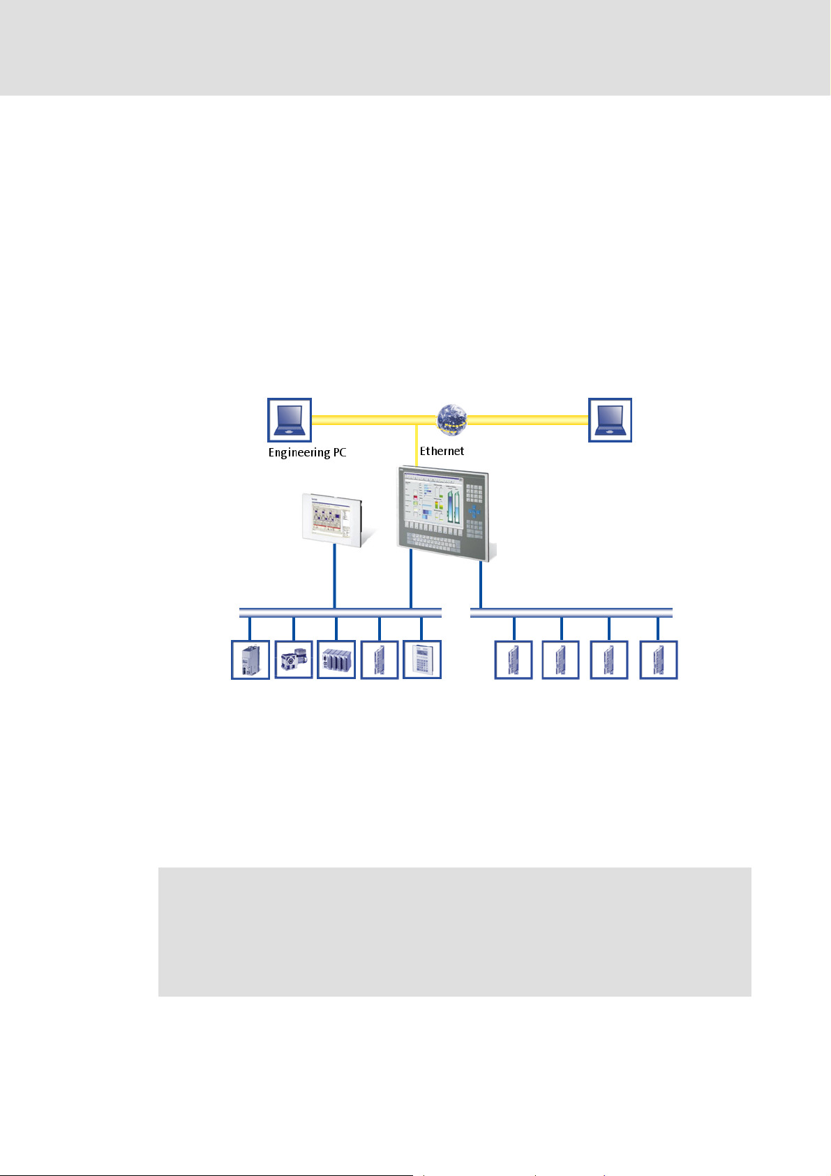
3 The "PC-based automation" system
Industrial PCs (IPCs) become more and more important in the field of automation
technology. Due to their scaling options and various combinations of visualisation and
control on one device, Industrial PCs provide clear advantages for many applications.
Lenze Industrial PCs are available in the following software equipments:
Industrial PC as component (optional with operating system) without any further
software
Industrial PC as visualisation system
Industrial PC as control and visualisation system
The "PC-based automation" system enables the centralised control of Logic and Motion
systems.
The "PC-based automation" system
For this purpose, Lenze provide coordinated system components:
Industrial PCs as control and visualisation system
– The IPC is the central component of the PC-based automation which controls the
Logic and Motion functionalities by means of the runtime software.
– The IPC communicates with the field devices via the fieldbus.
– The IPCs are available in different designs.
Note!
The "PC-based automation" system furthermore contains the EL 1xx PLC HMI
series. These devices clearly differ from the Industrial PCs with regard to the
performance and various other details. Nevertheless the devices of the
EL 1xx PLC HMI series are able to perform smaller control functions.
1.3 EN - 07/2012 L 21
Page 22

PLC Designer V2.x| Lenze Application Samples
The "PC-based automation" system
Engineering tools for the Engineering PC
– The Engineering PC communicates with the IPC via Ethernet.
– Use the various Engineering tools to configure and parameterise the system.
Fieldbuses
Field devices
22 L 1.3 EN - 07/2012
Page 23
4 Requirements
4.1 System requirements
PLC Designer V2.x| Lenze Application Samples
Requirements
System requirements
Hardware PC/notebook Industrial PC with PLC (Logic) from
Operating system Windows XP Windows CE
Lenze software required »PLC Designer« V2.2.4.x L-force Logic
Further requirements • 100 MB of free hard disk memory • CAN bus system
4.2 What is the PLC Designer?
The »PLC Designer« is a Lenze engineering software for programming the PLC of the Lenze
Industrial PC.
Properties
Five different editors for the programming languages standardised in the IEC 61131-3,
and a very powerful CFC editor are provided. They serve to create individual programs,
and to trigger the functions of our L-force Logic & Motion runtime software.
By means of the integrated visualisation the processes are shown, in order to obtain all
important pieces of information at a glance during commissioning.
Engineering PC IPC (controller)
firmware V2.0
• CAN nodes (depending on the
respective example application)
1.3 EN - 07/2012 L 23
Page 24

PLC Designer V2.x| Lenze Application Samples
Requirements
Where can I receive a full version of the PLC Designer?
4.3 Where can I receive a full version of the PLC Designer?
The »PLC Designer« is provided for download in the Lenze Application Knowledge Base
(AKB) :
http://akb.lenze.de/akb/infopool.nsf/html/Frame-Softwaredownload
The AKB is a product- and application-oriented collection of information provided by Lenze.
Alternatively you can install the »PLC Designer« from the CD supplied with the
Industrial PC.
4.3.1 Installation
How to install the »PLC Designer«:
1. Select »PLC Designer« to save the full version as a packed ZIP file on your PC
(Engineering PC).
• Unpack the ZIP file PlcDesigner_V2.3.x.zip on your PC (file size approximately
45MB).
• The ZIP file contains an installation file.
or
Start the PLCDesigner_V2.3..x.exe installation file from the CD supplied with the
Industrial PC.
2. Start the EXE file and follow the installation instructions
3. After the installation the »PLC Designer« can be started.
Further information and basics regarding the »PLC Designer« can be found in the
following documentation:
PLC Designer software manual
The manual is available on the CD supplied or on the Internet.
If the »PLC Designer« is already installed, carry out an update of the version available or
install the full version parallel to the version available.
Installing the target systems
Furthermore the »PLC Designer« target setup has to be installed, containing the
information required for controlling the target systems.
For the installation, proceed like for the installation of the »PLC Designer«.
24 L 1.3 EN - 07/2012
Page 25
PLC Designer V2.x| Lenze Application Samples
5 System bus (CAN) / CANopen
Lenze device series 8400, 9400, 9300, and ECS have an on-board system bus (CAN)
connection. The protocol used there is a subset of CANopen. Thus the devices are not
CANopen-compliant but can be driven by a CANopen-compatible control system under "Lforce Controls" - also in connection with other CANopen-compatible nodes.
Tip!
Detailed information on the system bus (CAN) can be found on the website of the
CAN User Organization CiA (CAN in Automation):
System bus (CAN) / CANopen
CANopen (Logic)
http://www.can-cia.org
5.1 CANopen (Logic)
A variety of different field devices can be connected to the CAN Logic line.
To create a CANopen bus line, use the Communication card MC-CAN2
CANopen (Logic)
The Logic bus line is used to operate controllers which...
carry out simple movements,
do not have a Motion functionality,
are controlled via PLC functionalities only.
The Lenze sample projects are available for the most common system configurations in
each case with selected field devices.
1.3 EN - 07/2012 L 25
( 26).
Page 26
PLC Designer V2.x| Lenze Application Samples
System bus (CAN) / CANopen
Communication card MC-CAN2
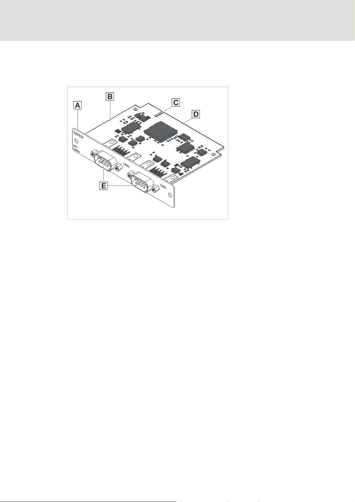
5.2 Communication card MC-CAN2
The MC-CAN2 communication card serves to connect an L-force Controller to the CAN bus
system CAN. The card provides two independent bus lines.
A Front panel
B Board
C Coding
D Connection
E CAN connection (CAN 2 /CAN 1)
MC-CAN2-001
26 L 1.3 EN - 07/2012
Page 27
PLC Designer V2.x| Lenze Application Samples
6 Commissioning the CANopen Logic bus
This chapter provides information on commissioning the CANopen Logic field devices in
the Lenze control system.
Depending on the field devices used, the following Lenze engineering tools are required:
»PLC Designer«
»Engineer«
»Global Drive Control« (GDC)
Tip!
For the application of further fieldbus systems, further Engineering software may
be required. Further information can be found in the corresponding
communication manuals.
Commissioning the CANopen Logic bus
Overview of the commissioning steps
6.1 Overview of the commissioning steps
Step Action Lenze software to be used
1. Open sample project
Commissioning field devices
Going online
Preparing the restart
2. Open sample project »PLC Designer«
In the following the individual commissioning steps are described. Follow the given stepby-step instructions to commission your system.
( 29)
( 28)
( 30)
More detailed information about how to work with the Lenze engineering tools
can be found in the corresponding manuals and online helps.
»Engineer« or
»Global Drive Control«
(depending on the used
device)
1.3 EN - 07/2012 L 27
Page 28

PLC Designer V2.x| Lenze Application Samples
Commissioning the CANopen Logic bus
Commissioning field devices
6.2 Commissioning field devices
Parameterise the field devices connected to the CANopen Logic bus either with the
»Engineer« or with the »GDC«, depending on the device.
The configuration of the CAN parameters takes place in the »PLC Designer«.
For this, observe the information in the ...
• documentation for the field devices;
• documentation for the »Engineer« / »GDC«, and »PLC Designer«.
Tip!
We recommend to commission each field device individually and then open the
suitable PLC program.
28 L 1.3 EN - 07/2012
Page 29

6.2.1 Going online
Field device Going online with Connection via
Industrial PC »Engineer« or
Inverter Drive 8400 StateLine /
HighLine
9400 Servo Drive HighLine »Engineer« • IPC as gateway
ECS servo system (ECSxE/S/P/M/A) »Global Drive Control« • IPC as gateway
8200 vector »Global Drive Control« • IPC as gateway
9300 »Global Drive Control« • IPC as gateway
1) CANopen only with system bus adapter EMF2177IB (if required, observe standard device specifications!)
PLC Designer V2.x| Lenze Application Samples
Commissioning the CANopen Logic bus
Commissioning field devices
Ethernet
»WebConfig«
»Engineer« • IPC as gateway
• CAN device interface
• Diagnostic adapter
• Ethernet module E94AYCEN
• CANopen module E94AYCCA
• CAN device interface
• CANopen module EMF2178IB
• CAN device interface 1)
• CAN module CAN PT/
E82ZAFCC010
• CAN device interface 1)
• CAN device interface 1)
Note!
Lenze recommend to use the connection type "IPC as gateway".
Depending on the device and connection type used, detailed information about
establishing a connection and "going online" can be found in the following
documents:
• (Software) manual/online help "PC-based automation"
Industrial PC - Parameter setting & Configuration
• Software manual/online help "PC based automation"
IPC as gateway - Parameter setting & Configuration
• Software manual/online help »Global Drive Control«
IPC as gateway - Parameter setting & Configuration
• Software manual/online help L-force »Engineer«
1.3 EN - 07/2012 L 29
Page 30

PLC Designer V2.x| Lenze Application Samples
Commissioning the CANopen Logic bus
Preparing the restart
6.3 Preparing the restart
In the control technology system you can use the control to transmit the entire parameter
setting via SDO initialisation to the field devices when the machine is switched on.
In accordance with DS301, the control always initialises the CAN parameters of the field
devices. Moreover, it can initialise further parameters. The values for this must be stored in
the control configuration under the Service Data Objects tab.
Usually, the control only transmits those SDO projects for which you have stored another
value than the standard value. The control does not
values in the field device. Thus, not all parameters changed there may be set correctly.
If you want to have a factory adjustment carried out in the field device before SDO
initialisation, go to the Parameter tab and set a checkmark at "Reset Node".
Note!
When a node is reset, the parameter setting in the field device which you have
made with the »Engineer« or the »Global Drive Control« gets lost. In this case,
you have to transmit all parameter values manually to the Service Data Objects
tab. This only makes sense when commissioning is completed and all
parameters are optimised. If you change something afterwards via the
»Engineer« or the »Global Drive Control« you have to maintain it again in the PLC
program.
compare these values with the existing
The Service Data Objects tab contains the codes which are written in the EDS file. The EDS
file contains all writable codes.
30 L 1.3 EN - 07/2012
Page 31

PLC Designer V2.x| Lenze Application Samples
6.3.1 Special features of the 9400 Servo Drives HighLine
Servo Drives 9400 are not purely parameterisable devices. They require an application
download, where several files are transmitted to the memory module.
To put a Servo Drive 9400 into operation, you can:
plug on the memory module.
transmit the application using the »Engineer«. For this, you must keep the original
»Engineer« project.
transmit the application using the L-force »Loader«. For this, you must export and keep
the required files from the »Engineer« project:
Commissioning the CANopen Logic bus
Preparing the restart
1.3 EN - 07/2012 L 31
Page 32

PLC Designer V2.x| Lenze Application Samples
Commissioning the CANopen Logic bus
Preparing the restart
6.3.2 Special features of the 8400 Inverter Drives
Inverter Drives 8400 are purely parameterisable devices.
To put an Inverter Drive 8400 into operation, you can transmit the application using the
»Engineer«. For this, you must keep the original »Engineer« project.
6.3.3 Commission 8200 vector frequency inverters
Connect the CANopen (E82ZAFUCxxx) fieldbus function module for CAN
communication.
CAN settings must be made in the »PLC Designer« because the transmission of the
settings to the 8200 vector frequency inverter is carried out from the control system.
6.3.4 Special features of the ECS servo system
In the ECS servo system, each device has a parameter memory which is only created
once when the parameter setting is created via the »Global Drive Control«. This is the
difference to CANopen devices where the parameterisation is written into the field
device at each system start.
The EMF2221IB card module serves to read parameters saved on an SD card or
SmartMedia card into every ECS device.
When using ECS devices, you cannot set all codes/parameters via the Service Data
Objects tab as the EDS files do not contain all codes/parameters.
32 L 1.3 EN - 07/2012
Page 33

PLC Designer V2.x| Lenze Application Samples
7 Commissioning a sample project
This chapter describes the commissioning of a sample project by means of examples. The
following requirements have to be met, so that the respective sample project can be used.
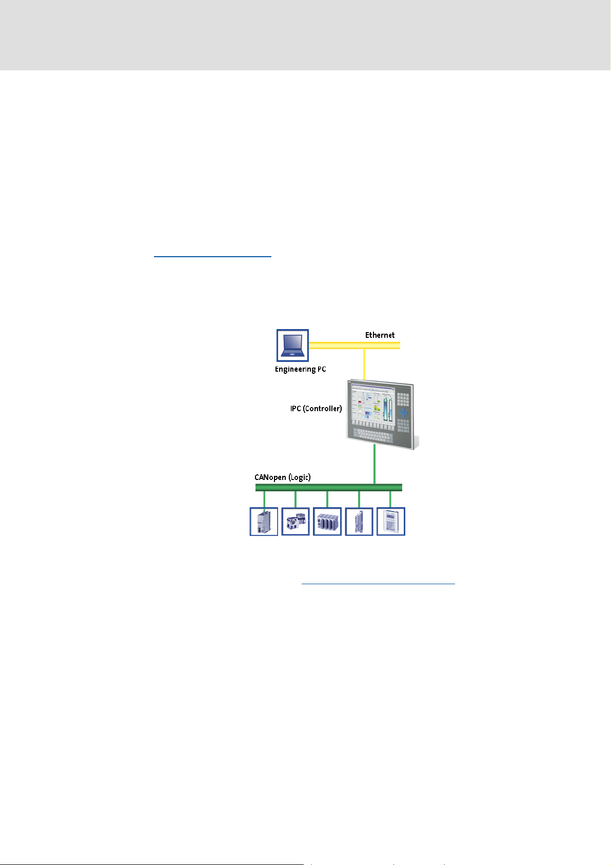
7.1 General system structure
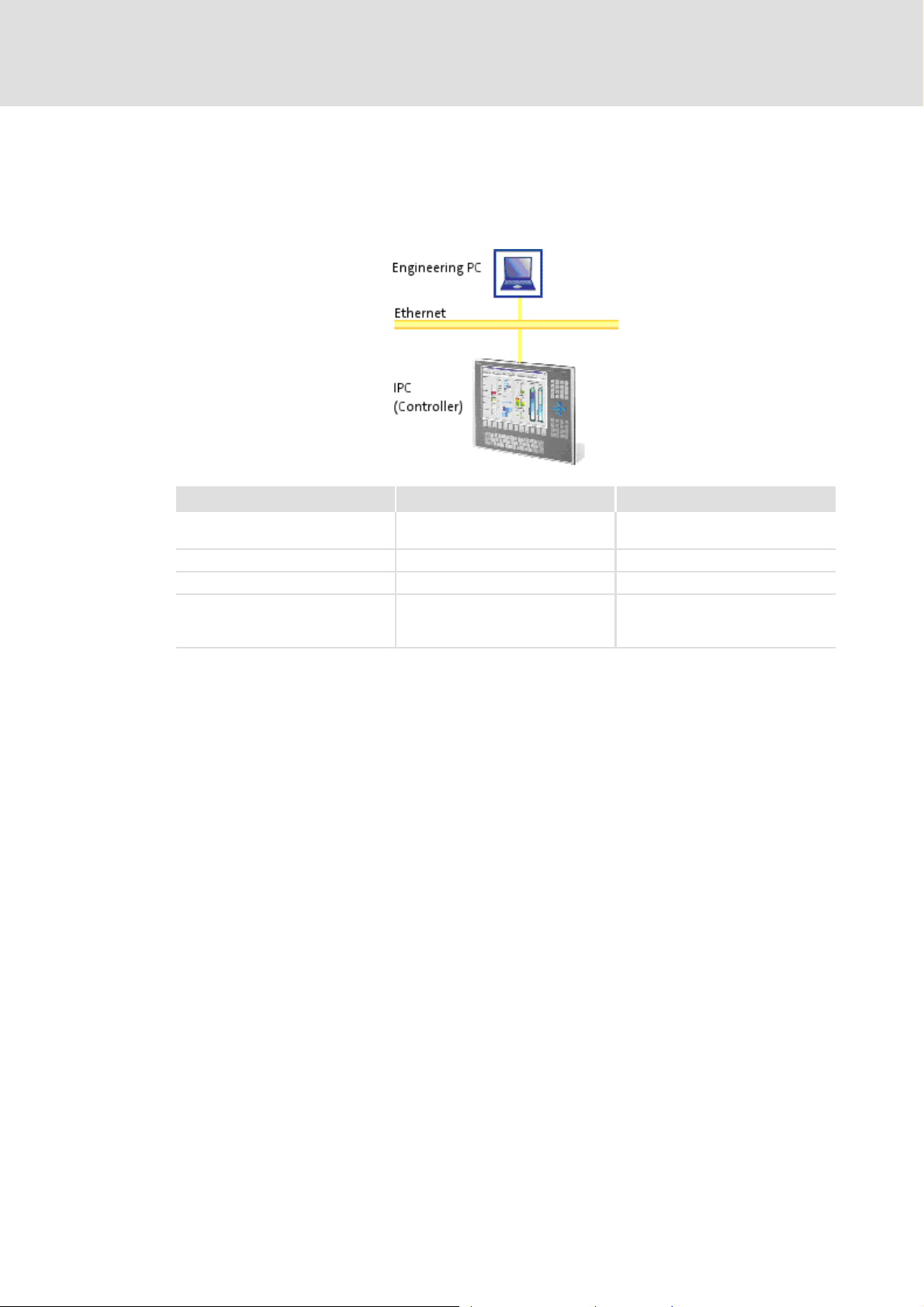
The Lenze project examples are based on the following system structure.
An Industrial PC (Logic) or an EL1xx (Logic) is the central control section of the system
configuration.
Commissioning a sample project
General system structure
[7-1] System structure with an Industrial PC (Logic)
[7-2] System structure with an EL1xx (Logic)
1.3 EN - 07/2012 L 33
Page 34

PLC Designer V2.x| Lenze Application Samples
Commissioning a sample project
Wiring the hardware
7.2 Wiring the hardware
Before you can work with the project, the hardware has to be connected to each other. The
sample projects are configured so that the motors rotate if a controller is used as CAN
node.
Connect the desired IPC (Industrial PC to PLC, or an EL1xx to a PLC) with the CAN nodes.
Connect the devices (Industrial PC, controllers, motors) with the corresponding voltage
supply
Further information on the electrical connections can be found in the
documentation supplied. Please read the mounting instructions supplied with
the controller first before you start working!
The mounting instructions contain safety instructions which must be observed!
Connect the components with a CAN bus cable.
– For this, use the CAN1 interface in the case of the Industrial PC. The CAN2 interface
is not required for the sample project.
– In the case of the EL100 there only is one CAN interface to be connected with the
components.
34 L 1.3 EN - 07/2012
Page 35

7.2.1 Configuring the CAN interface
For the configuration of the CAN interface the different hardware
(Industrial PC and EL1xx) is to be observed.
Industrial PC
In the case of the Industrial PC you configure the CAN bus using the »PLC Designer«.
EL1xx
In the case of the EL1xx, the device, and additionally the CAN bus must be configured
in the »PLC Designer«.
How to proceed in the case of the EL1xx:
1. On the EL 1xx, click StartSettingsControl PanelFieldbus
2. Configure the CAN interface in the following dialog window:
PLC Designer V2.x| Lenze Application Samples
Commissioning a sample project
Wiring the hardware
EL 1xx CAN device node: node address
of the EL 1xx within a CAN network.
Baud rate: transmission speed of the
fieldbus. The baud rate must be
identical for each fieldbus node within
a network.
According to the baud rate, the
fieldbus parameters are set.
3. Click the Save button to save the settings.
Since the »PLC Designer« accesses the Industrial PC or the EL1xx via Ethernet, connect the
Industrial PC or the EL1xx device to your Engineering PC via a network cable.
Note!
• During initial commissioning, observe the following predefined IP addresses:
– Engineering PC: 192.168.5.100
– Industrial PC: 192.168.5.99
• The network setting for the EL1xx is set to DHCP and has to be set to a fixed
IP address first, so that communication is possible.
1.3 EN - 07/2012 L 35
Page 36

PLC Designer V2.x| Lenze Application Samples
Commissioning a sample project
Wiring the hardware
7.2.2 Configuring an EL1xx Ethernet interface
How to configure the EL1xxx:
1. Click StartSettingsNetwork and Dial-up Connections for the EL 1xx.
2. Click the Dm9CE1 connection and configure the network interface:
3. Click the button to save the settings.
Note!
Changes carried out are not written into the registry automatically; in the case
of a restart, they are lost.
In order to save changes permanently...
•Click Start Settings Control PanelRegistry on the EL1xxx.
• Click the Save button to save the settings.
Further information can be found in the following documentation:
• EL 1xx - HMI with Windows® CE
• Industrial PC - Parameter setting & configuration
36 L 1.3 EN - 07/2012
Page 37

PLC Designer V2.x| Lenze Application Samples
7.3 Opening a project in the »PLC Designer«
The project contains all objects of a control program.
A project is saved in a file. The file name complies with the project name.
In the case of a standard installation you start the »PLC Designer« at the Engineering PC
via:
StartLenzePLC Designer V2.3.xPLC Designer
After starting the »PLC Designer«, a project can be loaded under FileOpen.
Commissioning a sample project
Opening a project in the »PLC Designer«
• Project files can be identified by the ending *.pro.
• Select the *.pro file type from the selection list to display the project files
available.
1.3 EN - 07/2012 L 37
Page 38

PLC Designer V2.x| Lenze Application Samples
Commissioning a sample project
Opening a project in the »PLC Designer«
7.3.1 Establishing communication with the Industrial PC or EL1xx
In the sample project communication between the devices of the system configuration has
already been established. It is reasonable to check communication before the project is
transferred to a PLC device.
How to check communication:
1. Open the Online menu in the menu bar and select the Communication parameters
menu item there.
2. In the "Communication parameters" dialog window the corresponding parameters
can be edited:
• In the Channels field, the name of the respective channel can be viewed.
Highlight the desired channel to display the associated data in the dialog area
on the right.
7.3.2 Starting the sample project
Transfer the sample project to the PLC device first to then start it.
How to start the sample project:
1. Open the Online menu in the menu bar and select the Log in menu item there.
• Confirm the following query on whether the program is to be saved with Yes.
• The project is transferred to the device.
2. Start the program on the HMI.
•Open the Online menu in the menu bar and select the Start menu item there.
The project will start on the HMI.
38 L 1.3 EN - 07/2012
Page 39

PLC Designer V2.x| Lenze Application Samples
Tip!
If the project is to be loaded automatically after a restart of the device, you can
install it as "Boot project".
How to install the project as boot project:
1. Open the Online menu in the menu bar
2. Select the Create boot project command.
• A dialog window is opened, displaying the files created.
3. Click OK to close the dialog window.
Commissioning a sample project
Opening a project in the »PLC Designer«
1.3 EN - 07/2012 L 39
Page 40

PLC Designer V2.x| Lenze Application Samples
Working with the sample projects
8 Working with the sample projects
The ready-configured sample projects are to facilitate the work with the Lenze
components for you. They include established system configurations representing typical
application cases. The objective is to obtain an executable Lenze automation system by
using low effort.
Depending on the application case, the sample projects can be optionally extended, and
thus they have to be adapted to the requirements in each case.
Where do I find the sample projects?
After a successful installation of the Lenze sample projects they can be found under:
ProgramsLenzeAppSamplesAppSamples_0100
Tip!
The»Engineer«sample projects are archived in ZIP format to allow you to send
them for instance by e-mail.
The »Engineer« supports project saving (FileSave archive) and project opening
(FileOpen archive) in ZIP format.
Structure of the sample projects
Each sample project consists of:
– Ready-configured project data in the »Engineer« or »Global Drive Control«(»GDC«)
(depending on the device used)
– Program code and visualisation in the »PLC Designer«. The following modes are
possible: automatic, manual (manual jog), service, homing (optional).
Mode Description
Automatic In the automatic mode a sequence runs over an infinite loop.
Manual In manual mode, the controller can be actuated by setting the individual
Service The service mode serves to adjust the controller.
Homing (available depending on the
device)
control bits manually (Jog1, Jog2, QSP, ErrorReset...). Like this, the controller
can be actuated in manual mode, for instance for cleaning or changing the
tools.
In the homing mode the drive is referenced.
40 L 1.3 EN - 07/2012
Page 41

PLC Designer V2.x| Lenze Application Samples
Working with the sample projects
8400 StateLine - "LAS_40_INTF_Can_84SL_Speed" sample project
8.1 8400 StateLine - "LAS_40_INTF_Can_84SL_Speed" sample project
Further information on the function libraries used in this project can be found in
the following section:
The L_S84_Drive8400.lib library
Standard procedure
How to commission the controller:
1. Commission 8400 Stateline. Commissioning
2. Load the project "LAS_40_INTF_Can_84SL_Speed.zip" to the controller using the Lforce »Engineer«. Open the »Engineer« project & go online
3. Open the "LAS_40_INTF_Can_84SL_Speed.pro" sample project in the »PLC
Designer«. Program structure in the »PLC Designer«
4. Load the project to the IPC/EL 1xx and go online.
8.1.1 Components used
( 235)
( 42)
( 43)
( 45)
[8-1] System configuration with EL x800 CAN master (ID=0, connection at CAN1) and 8400 StateLine (CAN node ID=5)
Industrial PC Field device
Hardware EL x800 8400 StateLine
Operating system IPC software from version Logic
7.02.x (release 2.2.x)
Lenze software required »PLC Designer« from version 20.3
L-force »Engineer« from version 2.12
Further requirements • CAN master ID = 0
• Connection to interface CAN 1
• Logic CAN 500kB
1.3 EN - 07/2012 L 41
From firmware V5.1
• CAN node ID = 5
• Motor: SDSGAI056-22
Page 42

PLC Designer V2.x| Lenze Application Samples
Working with the sample projects
8400 StateLine - "LAS_40_INTF_Can_84SL_Speed" sample project
8.1.2 Short overview of the functions
Mode Description
Automatic In the automatic mode a sequence runs over an infinite loop.
Selection:
•Travel for three seconds at speed1,
•then for five seconds at speed2,
• Start with speed1 again.
Manual In manual mode, the controller can be actuated by setting the individual
Service The service mode serves to adjust the controller.
8.1.2.1 Commissioning
control bits manually (Jog1, Jog2, QSP, ErrorReset...). Like this, the controller
can be actuated in manual mode, for instance for cleaning or changing the
tools.
Selection:
• Travel in positive direction for one second,
•Stop for one second,
• Travel in negative direction for one second.
Read the mounting instructions supplied with the controller first before you start
working!
The mounting instructions contain safety instructions which must be observed!
1. Wire the power connections
– Use the mounting instructions supplied with the controller to correctly use the
power connections according to the requirements of your device.
2. Wire the control terminals
3. Connect USB diagnostic adapter.
4. Switch on the voltage supply of the controller.
– Connect mains voltage.
When the green LED "DRV-RDY" is blinking and the red LED "DRV-ERR" is off, the controller
is ready to start and you can continue with the commissioning.
42 L 1.3 EN - 07/2012
Page 43

PLC Designer V2.x| Lenze Application Samples
8400 StateLine - "LAS_40_INTF_Can_84SL_Speed" sample project
8.1.2.2 Open the »Engineer« project & go online
Detailed infomation on the general handling of the »Engineer« can be found in
the online help for the »Engineer«, which you can call with [F1].
How to open the sample project in the »Engineer«:
1. Start »Engineer«.
2. With the command FileOpen archive, open the project
"LAS_40_INTF_Can_84SL_Speed".
3. Insert the desired motor in the configuration:
– Highlight controller, select the desired motor with the command Insert a component
on the Motors tab
Working with the sample projects
– By clicking Complete, insert the selection in the »Engineer« project.
1.3 EN - 07/2012 L 43
Page 44

PLC Designer V2.x| Lenze Application Samples
Working with the sample projects
8400 StateLine - "LAS_40_INTF_Can_84SL_Speed" sample project
4. Update the project by clicking :
• Select the option Rebuild all
• Click the Build button to update the project.
5. Going online
– After a connection to the controller has been established successfully, the following
status is displayed in the Status line:
6. Download parameter set
– This command causes parameter settings in the controller to be overwritten by
parameter settings of the »Engineer« project.
44 L 1.3 EN - 07/2012
Page 45

PLC Designer V2.x| Lenze Application Samples
8400 StateLine - "LAS_40_INTF_Can_84SL_Speed" sample project
8.1.3 Program structure in the »PLC Designer«
How to proceed:
1. In the »PLC Designer«, open the "LAS_40_INTF_Can_84SL_Speed.pro" sample
project.
2. Load the project to the IPC and Go online.
8.1.3.1 Control configuration
The CAN master (ID = 0) is the control section of the system configuration
Below the CAN master the 8400 StateLine(CAN node ID = 5) is attached.
– The 8400 StateLine is embedded in the form of a device-independent EDS file
(LenzeDrive_Can1_4Word).
One PDO for CAN-Input and one PDO for CAN-Output is used, respectively.
Working with the sample projects
1.3 EN - 07/2012 L 45
Page 46

PLC Designer V2.x| Lenze Application Samples
Working with the sample projects
8400 StateLine - "LAS_40_INTF_Can_84SL_Speed" sample project
8.1.3.2 Program organisation units
"Main" program
The "Main (PRG)" program is the basic program for processing the program sequences:
initialisation of the controller and selection of the different modes.
46 L 1.3 EN - 07/2012
Page 47

PLC Designer V2.x| Lenze Application Samples
Working with the sample projects
8400 StateLine - "LAS_40_INTF_Can_84SL_Speed" sample project
"Drive" program
The "DRIVE (PRG)" program actuates the controller by means of the
L_S84_ActuatorSpeedSL1 function block.
The data are copied to the control configuration via the selection of the Can NodeID
(byNodeNumber) and the CAN master node number (byMasterNumber).
The DriveControl and DriveStatus structures serve to transmit the control and status
signals.
"PLC_PRG" program
The "PLC_PRG (PRG)" program contains all program calls.
1.3 EN - 07/2012 L 47
Page 48

PLC Designer V2.x| Lenze Application Samples
Working with the sample projects
8400 StateLine - "LAS_40_INTF_Can_84SL_Speed" sample project
8.1.4 Operation via the visualisations in the »PLC Designer«
8.1.4.1 Information/home page
Select mode Manufacturer information Version identifier Error message
Parameter
selection
Via the buttons in area , the mode (automatic, manual, service) can be selected.
In area services (parameter transfer and CAN diagnostics) can be selected.
The button in area refers to the home page which displays the version identifier of
the project in area .
Dialog box shows the status of the machine.
Control field shows the error message status.
–The Error Reset button resets the error message.
Information/home page Status
48 L 1.3 EN - 07/2012
Page 49

8.1.4.2 Automatic mode
PLC Designer V2.x| Lenze Application Samples
Working with the sample projects
8400 StateLine - "LAS_40_INTF_Can_84SL_Speed" sample project
Select mode Stop button Actual speed Error message
Start button Status Status
Button selects the automatic mode.
Button starts the motion profile.
Button inhibits the motion profile.
Display field shows the mode status.
Display field shows the current speed (Speed Value variable).
Dialog box shows the status of the machine.
Control field activates the error group signal.
–The Error Reset button resets the error message.
1.3 EN - 07/2012 L 49
Page 50

PLC Designer V2.x| Lenze Application Samples
Working with the sample projects
8400 StateLine - "LAS_40_INTF_Can_84SL_Speed" sample project
8.1.4.3 Manual mode ("Manual jog")
The 8400 StateLine can be controlled by means of the visualisation of block
L_S84ActuatorSpeedSL in manual operation. Via the visualisation of block
L_S84ReadErrorCode the current error can be read out.
Select mode Reading out an
Control/status panel
Button selects the manual (manual jog) mode.
In the control and status panel the FB for controlling the 8400 Stateline is visualised.
Note: Enable the controller via FB input xEnable to activate the manual mode
Afterwards the controller can be operated via the visualisation in manual operation.
The xQsp button must be activated to activate quick stop.
Further information on the FB can be found in the following section:
L_S84_ActuatorSpeedSL - actuation of the 8400 StateLine controller
Area visualises the FB for reading out the errors from the controller.
Further information on the FB can be found in the following section:
L_S84_ReadErrorCode - read out error status
error
.
( 238)
( 241)
50 L 1.3 EN - 07/2012
Page 51

Control/status panel
PLC Designer V2.x| Lenze Application Samples
Working with the sample projects
8400 StateLine - "LAS_40_INTF_Can_84SL_Speed" sample project
Actuation of the controller Status of the controller
CAN address
Number of the CAN master
Switch on drive after mains switching
Enable drive
Activate quick stop
Activate fixed speed (Jog 1)
Activate fixed speed (Jog 2)
Set external error
Reset error
Set clockwise (CW) rotation/counter-clockwise
(CCW) rotation
Select speed setpoint in [%]
CAN communication OK
Error active
Controller ready
Minimum speed limit value not reached
Drive enabled
Actual speed value
CAN status
Further information on the FB can be found in the following section:
L_S84_ActuatorSpeedSL - actuation of the 8400 StateLine controller
( 238)
1.3 EN - 07/2012 L 51
Page 52

PLC Designer V2.x| Lenze Application Samples
Working with the sample projects
8400 StateLine - "LAS_40_INTF_Can_84SL_Speed" sample project
Read out error
Actuation of the controller Status of the controller
Read out error
CAN address
Number of the CAN master
Use second SDO
Error text display
Error read out
Function block active
Reading out error has failed
Further information on the FB can be found in the following section:
L_S84_ReadErrorCode - read out error status
( 241)
52 L 1.3 EN - 07/2012
Page 53

8.1.4.4 Service mode
PLC Designer V2.x| Lenze Application Samples
Working with the sample projects
8400 StateLine - "LAS_40_INTF_Can_84SL_Speed" sample project
Select mode Stop button Status of the service mode
Start button Activate clockwise
rotation (Cw)
Button selects the service mode.
Button starts the motion profile.
Button inhibits the motion profile.
Button selects clockwise rotation (clockwise rotating direction of the motor).
Display field indicates the status of the mode.
Display field indicates the current speed (variable Speed Value).
Display field shows the current speed setpoint.
– Possible setpoint data for the motion profile: 0 ... 100%.
In area , status information is displayed and errors can be reset.
Actual speed Setpoint speed
1.3 EN - 07/2012 L 53
Page 54

PLC Designer V2.x| Lenze Application Samples
Working with the sample projects
8400 StateLine - "LAS_40_INTF_Can_84SL_Speed" sample project
8.1.4.5 Parameter transfer
The Parameter button selects the visualisation of the parameter FBs.
The mode selected last remains active.
You can use the FBs to...
– read individual parameters
– write individual parameters
– write a fixed parameter list
Read parameters Write parameters
Write parameter table
Area shows the FB for reading parameters.
Area shows the FB for writing a parameter table.
Area shows the FB for writing parameters.
– The parameters read can be viewed in the »PLC Designer« on the Blocks tab in the
Parameter transfer directory of FB L_S84_SDOList84SL.
54 L 1.3 EN - 07/2012
Page 55

PLC Designer V2.x| Lenze Application Samples
Working with the sample projects
8400 StateLine - "LAS_40_INTF_Can_84SL_Speed" sample project
Reading a parameter - L_SCB_ParRead function block
Actuation of the controller Status of the controller
Read out parameter
CAN address
Number of the CAN master
Parameter index
Basic value code no. 24575 - C11 = 24564
Parameter subindex
Use second SDO
Parameter read out
Function block active
Reading out parameter has failed
Time-out
Parameter display
Number of bytes read
Further information on the FB can be found in the following section:
L_SCB_ParRead - read parameter
( 288)
1.3 EN - 07/2012 L 55
Page 56

PLC Designer V2.x| Lenze Application Samples
Working with the sample projects
8400 StateLine - "LAS_40_INTF_Can_84SL_Speed" sample project
Writing a parameter - L_SCB_ParWrite function block
Actuation of the controller Status of the controller
Write parameter
CAN address
Number of the CAN master
Basic value code no. 24575 - C11 = 24564
Parameter index
Parameter subindex
Data
Number of bytes to be transmitted
Use second SDO
Parameter written
Function block active
Writing parameter has failed
Time-out
Further information on the FB can be found in the following section:
L_SCB_ParWrite - write parameter
( 291)
Writing a parameter table - function block
Actuation of the controller Status of the controller
Read/write parameter
CAN address
Number of the CAN master
Use CAN address and master number entered
Use input code number as index
Parameter list read/written
Function block active
Reading/writing parameter
has failed
Error number
Error in table line
Further information on the FB can be found in the following section:
L_SCB_SDO_TransferTable - transfer parameter list
56 L 1.3 EN - 07/2012
( 299)
Page 57

8.1.4.6 CAN diagnostics
The CanDiagnostic button selects the diagnostics of the CAN bus.
The mode selected last remains active.
This area shows the status of the master and slaves, which are integrated in the control
configuration.
PLC Designer V2.x| Lenze Application Samples
Working with the sample projects
8400 StateLine - "LAS_40_INTF_Can_84SL_Speed" sample project
Status of the CAN master (ID=0)
Status of the CAN slave (node-ID=5)
1.3 EN - 07/2012 L 57
Page 58

PLC Designer V2.x| Lenze Application Samples
Working with the sample projects
8400 StateLine - "LAS_40_INTF_Can_84SL_Speed" sample project
8.1.5 Interface assignment in the »Engineer«
CAN monitoring is activated in the project:
[8-2] Time monitoring RPDO 1- RPDO4 3000 ms, "Error" response in the controller
The second SDO (code C00366) is activated for communication.
All digital inputs (apart from bCInh) are
high active.
o
[8-3] Assignment of the digital inputs
All digital outputs are high active.
[8-4] Assignment of the digital outputs
58 L 1.3 EN - 07/2012
Page 59

PLC Designer V2.x| Lenze Application Samples
Working with the sample projects
8400 StateLine - "LAS_40_INTF_Can_84SL_Speed" sample project
The following bits from the wCtrl are
assigned and are mapped to LA_NCtrl:
bCtrl_B1 = xSwitchOn
bCtrl_B2 = xQSP
bCtrl_B3 = xEnable
bCtrl_B7 = xErrorReset
bCtrl_B8 = xRampDown
bCtrl_B11 = xDCBrake
bCtrl_B12 = xJog1
bCtrl_B13 = xJog2
bCtrl_B14 = xErrorSet
bCtrl_B15 = xSetSpeedCCw
[8-5] Assignment CanIn1
1.3 EN - 07/2012 L 59
Page 60

PLC Designer V2.x| Lenze Application Samples
Working with the sample projects
8400 StateLine - "LAS_40_INTF_Can_84SL_Speed" sample project
The following bits from the wState are
assigned and mapped by LA_NCtrl:
bState_B00 = xDriveReady
bState_B01 = xDriveEnabled
bState_B02 = xDriveError
bState_B06 = xQmin
[8-6] Assignment CanOut1
60 L 1.3 EN - 07/2012
Page 61

PLC Designer V2.x| Lenze Application Samples
Working with the sample projects
8400 HighLine - "LAS_40_INTF_Can_84HL_TabPos" sample project
8.2 8400 HighLine - "LAS_40_INTF_Can_84HL_TabPos" sample project
Further information on the function libraries used in this project can be found in
the following section:
The L_S84_Drive8400.lib library
Standard procedure
How to commission the controller:
1. Commission 8400 HighLine. Commissioning
2. Load the project "LAS_40_INTF_Can_84HL_TabPos.zip" to the controller using the
L-force »Engineer«. Open the »Engineer« project & go online
3. Open the "LAS_40_INTF_Can_84HL_TabPos.pro" sample project in the »PLC
Designer« Program structure in the »PLC Designer«
4. Load the project to the IPC/EL 1xx and go online.
8.2.1 Components used
( 235)
( 62)
( 63)
( 65)
[8-7] System configuration with EL x800 CAN master (ID=0, connection at CAN1) and 8400 HighLine (CAN node ID=5)
Industrial PC Field device
Hardware EL x800 8400 HighLine
Operating system IPC software from version Logic
7.02.x (release 2.2.x)
Lenze software required »PLC Designer« from version 2.3.x
L-force »Engineer« from version 2.12
Further requirements • CAN master ID = 0
• Connection to interface CAN 1
• Logic CAN 500kB
1.3 EN - 07/2012 L 61
From firmware V5.0
• CAN node ID = 5
• Motor: SDSGAI056-22
Page 62

PLC Designer V2.x| Lenze Application Samples
Working with the sample projects
8400 HighLine - "LAS_40_INTF_Can_84HL_TabPos" sample project
8.2.2 Short overview of the functions
Mode Description
Automatic In the automatic mode a sequence runs over an infinite loop.
Selection:
When the drive is referenced...
1.Travel to Position 1,
2.Travel to Position 2,
3.Start at (1.) again.
Manual In manual mode, the controller can be actuated by setting the individual
Service The service mode serves to adjust the controller.
Homing In the homing mode the drive is referenced.
control bits manually (Jog1, Jog2, QSP, ErrorReset...). Like this, the controller
can be actuated in manual mode, for instance for cleaning or changing the
tools.
Selection:
• Travel in positive direction for one second,
•Stop for one second,
• Travel in negative direction for one second.
• Either the home position is set directly, or a homing is started.
8.2.3 Commissioning
Read the mounting instructions supplied with the controller first before you start
working!
1. Wire the power connections
2. Wire the control terminals
3. Connect USB diagnostic adapter.
4. Switch on the voltage supply of the controller.
When the green LED "DRV-RDY" is blinking and the red LED "DRV-ERR" is off, the controller
is ready to start and you can continue with the commissioning.
The mounting instructions contain safety instructions which must be observed!
– Use the mounting instructions supplied with the controller to correctly use the
power connections according to the requirements of your device.
– Connect mains voltage.
62 L 1.3 EN - 07/2012
Page 63

PLC Designer V2.x| Lenze Application Samples
8400 HighLine - "LAS_40_INTF_Can_84HL_TabPos" sample project
8.2.3.1 Open the »Engineer« project & go online
Detailed infomation on the general handling of the »Engineer« can be found in
the online help for the »Engineer«, which you can call with [F1].
How to open the sample project in the »Engineer«:
1. Start »Engineer«.
2. With the command FileOpen archive , open the project
"LAS_40_INTF_Can_84HL_TabPos".
3. Insert the desired motor in the configuration:
– Highlight controller, select the desired motor with the command Insert a component
on the Motors tab
Working with the sample projects
– By clicking Complete, insert the selection in the »Engineer« project.
1.3 EN - 07/2012 L 63
Page 64

PLC Designer V2.x| Lenze Application Samples
Working with the sample projects
8400 HighLine - "LAS_40_INTF_Can_84HL_TabPos" sample project
4. Update the project by clicking :
• Select the option Rebuild all
• Click the Build button to update the project.
5. Going online
– After a connection to the controller has been established successfully, the following
status is displayed in the Status line:
6. Download parameter set
– This command causes parameter settings in the controller to be overwritten by
parameter settings of the »Engineer« project.
64 L 1.3 EN - 07/2012
Page 65

PLC Designer V2.x| Lenze Application Samples
8400 HighLine - "LAS_40_INTF_Can_84HL_TabPos" sample project
8.2.4 Program structure in the »PLC Designer«
How to proceed:
1. In the »PLC Designer«, open the "LAS_40_INTF_Can_84HL_TabPos.pro" sample
project.
2. Load the project to the IPC and Go online.
8.2.4.1 Control configuration
The CAN master (ID = 0) is the control section of the system configuration
Below the CAN master the 8400 HighLine (CAN node ID = 5) is attached.
– The 8400 HighLine is embedded in the form of a device-independent EDS file
(LenzeDrive_Can2_8Word).
Two PDOs for CAN-Input and CAN-Output are used, respectively.
Working with the sample projects
The transmission mode is sync-controlled (10 ms).
1.3 EN - 07/2012 L 65
Page 66

PLC Designer V2.x| Lenze Application Samples
Working with the sample projects
8400 HighLine - "LAS_40_INTF_Can_84HL_TabPos" sample project
8.2.4.2 Program organisation units
"Main" program
The "Main (PRG)" program is the basic program for processing the program sequences:
initialisation of the controller and selection of the different modes.
66 L 1.3 EN - 07/2012
Page 67

PLC Designer V2.x| Lenze Application Samples
Working with the sample projects
8400 HighLine - "LAS_40_INTF_Can_84HL_TabPos" sample project
"Drive" program
The "DRIVE (PRG)" program actuates the controller by means of the
L_S84_TablePositioningHL function block.
The machine constants are conditioned by means of the L_SSC_SetAxisData block and
are provided at the AxisData input as structure.
The DriveControl and DriveStatus structures serve to transmit the control and status
signals within one PDO. Since an individual PDO does not suffice for all modes, block
L_SCB_PutNodeDataTxPDO2 provides a further PDO for the transmission of the speed
setpoint for the service mode.
By selecting the CAN node ID (byNodeNumber) and the CAN master node number
(byMasterNumber), the data can be copied to the control configuration.
1.3 EN - 07/2012 L 67
Page 68

PLC Designer V2.x| Lenze Application Samples
Working with the sample projects
8400 HighLine - "LAS_40_INTF_Can_84HL_TabPos" sample project
"PLC_PRG" program
The "PLC_PRG (PRG)" program contains all program calls.
68 L 1.3 EN - 07/2012
Page 69

PLC Designer V2.x| Lenze Application Samples
8400 HighLine - "LAS_40_INTF_Can_84HL_TabPos" sample project
8.2.5 Operation via the visualisations in the »PLC Designer«
8.2.5.1 Information/home page
Working with the sample projects
Select mode Manufacturer information Version identifier Error message
Parameter
selection
Via the buttons in area , the mode (automatic, manual, service, homing) can be
selected.
In area services (parameter transfer and CAN diagnostics) can be selected.
The button in area refers to the home page which displays the version identifier of
the project in area .
Dialog box shows the status of the machine.
Control field shows the error message status.
–The Error Reset button resets the error message.
Information/home page Status
1.3 EN - 07/2012 L 69
Page 70

PLC Designer V2.x| Lenze Application Samples
Working with the sample projects
8400 HighLine - "LAS_40_INTF_Can_84HL_TabPos" sample project
8.2.5.2 Automatic mode
Select mode Stop button Current profile
Start button Mode status Set position
Button selects the automatic mode.
Button starts the motion profile.
Button inhibits the motion profile.
Display field shows the mode status.
Display field shows the current profile number.
Display field shows the set position.
Dialog box shows the current position (Actual Position variable).
number
Current position
70 L 1.3 EN - 07/2012
Page 71

8400 HighLine - "LAS_40_INTF_Can_84HL_TabPos" sample project
8.2.5.3 Manual mode ("Manual jog")
The 8400 StateLine can be controlled by means of the visualisation of block
L_S84_TablePositioningHL in manual operation. Via the visualisation of block
L_S84ReadErrorCode the current error can be read out.
PLC Designer V2.x| Lenze Application Samples
Working with the sample projects
Select mode Reading out an
Control/status panel
error
Button selects the manual (manual jog) mode.
In the control and status panel the FB for controlling the 8400 Stateline is visualised.
By means of the visualisation of block L_S84_TablePositioningHL, the 8400 HighLine
can be operated in manual operation (byProfilenumber = 2).
Note: Enable the controller via FB input xEnable to activate manual mode
. The
controller can then be actuated via the visualisation in manual operation. The xQsp
button must be activated so that quick stop is activated.
Profile number Function
byProfileNumber = 1 Homing
byProfileNumber = 2 Manual jog
byProfileNumber = 3 or 4 Positioning
Further information on the FB can be found in the following section:
L_S84_TablePositioningHL - profile data record management
( 243)
Area visualises the FB for reading out the errors from the controller.
Further information on the FB can be found in the following section:
L_S84_ReadErrorCode - read out error status
1.3 EN - 07/2012 L 71
( 241)
Page 72

PLC Designer V2.x| Lenze Application Samples
Working with the sample projects
8400 HighLine - "LAS_40_INTF_Can_84HL_TabPos" sample project
Control/status panel
Actuation of the controller Status of the controller
CAN address
Number of the CAN master
Enable drive
Activate quick stop
Reset error
Define reference
Enable positioning
Enable override
Activate manual jog in positive direction
Activate manual jog in negative direction
Target position (not available)
Speed override in [%]
Operating mode (not available)
Profile number:
0 = Speed follower
1 = Homing
2 = Manual jog
≥3 = Positioning
CAN communication OK
Error active
Controller ready
Speed is zero
Drive enabled
Quick stop active
Reference known
Positioning active
Target position reached
Hardware limit switch positive
Hardware limit switch negative
... Status of digital inputs 5 ... 7
Actual position
Actual speed
CAN status
Further information on the FB can be found in the following section:
L_S84_TablePositioningHL - profile data record management
( 243)
72 L 1.3 EN - 07/2012
Page 73

PLC Designer V2.x| Lenze Application Samples
Working with the sample projects
8400 HighLine - "LAS_40_INTF_Can_84HL_TabPos" sample project
Read out error
Actuation of the controller Status of the controller
Read out error
CAN address
Number of the CAN master
Use second SDO
Error text display
Error read out
Function block active
Reading out error has failed
Further information on the FB can be found in the following section:
L_S84_ReadErrorCode - read out error status
( 241)
1.3 EN - 07/2012 L 73
Page 74

PLC Designer V2.x| Lenze Application Samples
Working with the sample projects
8400 HighLine - "LAS_40_INTF_Can_84HL_TabPos" sample project
8.2.5.4 Service mode
Select mode Stop button Status of the service mode
Start button Activate clockwise
rotation
Button selects the service mode.
Button starts the motion profile.
Button inhibits the motion profile.
Button selects clockwise rotation (clockwise rotating direction of the motor).
Display field indicates the status of the mode.
Display field indicates the current speed (variable Speed Value).
Display field shows the current speed setpoint.
– Possible setpoint data for the motion profile: 0 ... 100%.
In area , status information is displayed and errors can be reset.
Actual speed Setpoint speed
74 L 1.3 EN - 07/2012
Page 75

8.2.5.5 Homing mode
PLC Designer V2.x| Lenze Application Samples
Working with the sample projects
8400 HighLine - "LAS_40_INTF_Can_84HL_TabPos" sample project
Select mode Stop button Status of the service mode
Start button Activate clockwise
rotation
Button selects the homing mode.
– The active standard setting in the controller is homing mode 12 (travel to negative
limit switch / digital input 3)
Button starts the homing.
Button stops homing.
Button sets the home position.
Button resets the home position.
– Set reference / Pos Act = 0 unit
Dialog box shows the homing status.
Dialog box signalises whether the homing has been completed successfully.
– After a successful homing, the display field is coloured in green.
Dialog box shows the current homing mode (code value).
Actual speed
1.3 EN - 07/2012 L 75
Page 76

PLC Designer V2.x| Lenze Application Samples
Working with the sample projects
8400 HighLine - "LAS_40_INTF_Can_84HL_TabPos" sample project
8.2.5.6 Parameter transfer
The Parameter button selects the visualisation of the parameter FBs.
The mode selected last remains active.
You can use the FBs to...
– read individual parameters
– write individual parameters
– write a fixed parameter list
Read parameters Write parameters
Read parameters
Area shows the FB for reading parameters.
Area shows the FB for writing a parameter table.
Area shows the FB for writing parameters.
76 L 1.3 EN - 07/2012
Page 77

PLC Designer V2.x| Lenze Application Samples
Working with the sample projects
8400 HighLine - "LAS_40_INTF_Can_84HL_TabPos" sample project
Reading a parameter - L_SCB_ParRead function block
Actuation of the controller Status of the controller
Read out parameter
CAN address
Number of the CAN master
Parameter index
Basic value code no. 24575 - C11 = 24564
Parameter subindex
Use second SDO
Parameter read out
Function block active
Reading out parameter has failed
Time-out
Parameter display
Number of bytes read
Further information on the FB can be found in the following section:
L_SCB_ParRead - read parameter
( 288)
1.3 EN - 07/2012 L 77
Page 78

PLC Designer V2.x| Lenze Application Samples
Working with the sample projects
8400 HighLine - "LAS_40_INTF_Can_84HL_TabPos" sample project
Writing a parameter - L_SCB_ParWrite function block
Actuation of the controller Status of the controller
Write parameter
CAN address
Number of the CAN master
Basic value code no. 24575 - C11 = 24564
Parameter index
Parameter subindex
Data
Number of bytes to be transmitted
Use second SDO
Parameter written
Function block active
Writing parameter has failed
Time-out
Further information on the FB can be found in the following section:
L_SCB_ParWrite - write parameter
( 291)
Writing a parameter table - function block
Actuation of the controller Status of the controller
Read/write parameter
CAN address
Number of the CAN master
Use CAN address/master number entered
Use input code number as index
Parameter list read/written
Function block active
Reading/writing parameter has failed
Error number
Error in table line
Further information on the FB can be found in the following section:
L_SCB_SDO_TransferTable - transfer parameter list
78 L 1.3 EN - 07/2012
( 299)
Page 79

8.2.5.7 CAN diagnostics
The CanDiagnostic button selects the diagnostics of the CAN bus.
The mode selected last remains active.
This area shows the status of the master and slaves, which are integrated in the control
configuration.
PLC Designer V2.x| Lenze Application Samples
Working with the sample projects
8400 HighLine - "LAS_40_INTF_Can_84HL_TabPos" sample project
Status of the CAN master (ID=0)
Status of the CAN slave (node-ID=5)
1.3 EN - 07/2012 L 79
Page 80

PLC Designer V2.x| Lenze Application Samples
Working with the sample projects
8400 HighLine - "LAS_40_INTF_Can_84HL_TabPos" sample project
8.2.6 Interface assignment in the »Engineer«
CAN monitoring is activated in the project:
[8-8] Time monitoring RPDO 1- RPDO4 3000 ms, "Error" response in the controller
The second SDO (code C00366) is activated for communication.
LS_DigitalInput_bIn1 = bQSP
LS_DigitalInput_bIn3 = LP_CanOut1.bState_B13 and
LA_TabPos.LimitSwitchPos
LS_DigitalInput_bIn4 = LP_CanOut1.bState_B12 and
LA_TabPos.LimitSwitchNeg
All digital inputs (apart from bCInh) are
high active.
[8-9] Assignment of the digital inputs
All digital outputs are high active.
[8-10] Assignment of the digital outputs
80 L 1.3 EN - 07/2012
Page 81

PLC Designer V2.x| Lenze Application Samples
Working with the sample projects
8400 HighLine - "LAS_40_INTF_Can_84HL_TabPos" sample project
[8-11] Assignment CanIn1
[8-12] Assignment CanIn2
1.3 EN - 07/2012 L 81
Page 82

PLC Designer V2.x| Lenze Application Samples
Working with the sample projects
8400 HighLine - "LAS_40_INTF_Can_84HL_TabPos" sample project
The following bits from wState are
assigned.
[8-13] Assignment CanOut1
82 L 1.3 EN - 07/2012
Page 83

PLC Designer V2.x| Lenze Application Samples
Working with the sample projects
9400 HighLine - "LAS_40_INTF_Can_94HL_Speed" sample project
8.3 9400 HighLine - "LAS_40_INTF_Can_94HL_Speed" sample project
Further information on the function libraries used in this project can be found in
the following section:
The L_S94_Drive9400.lib library
Standard procedure
( 246)
How to commission the controller:
1. Commission the 9400 HighLine.
2. Load the project "LAS_40_INTF_Can_94SL_Speed.zip" to the controller using the L-
force »Engineer«. Open the »Engineer« project & go online
3. Open the "LAS_40_INTF_Can_94HL_Speed.pro" sample project in the »PLC
Designer«. Program structure in the »PLC Designer«
4. Load the project to the IPC/EL 1xx and go online.
( 87)
( 85)
1.3 EN - 07/2012 L 83
Page 84

PLC Designer V2.x| Lenze Application Samples
Working with the sample projects
9400 HighLine - "LAS_40_INTF_Can_94HL_Speed" sample project
8.3.1 Components used
[8-14] System configuration with EL x800 CAN master (ID=0, connection at CAN1) and 9400 HighLine (CAN node ID=5)
Hardware EL x800 9400 HighLine
Operating system IPC software from version Logic
Lenze software required »PLC Designer« from version 20.3
Further requirements • CAN master ID = 0
8.3.2 Short overview of the functions
Mode Description
Automatic In the automatic mode a sequence runs over an infinite loop.
Manual In manual mode, the controller can be actuated by setting the individual
Service The service mode serves to adjust the controller.
Industrial PC Field device
7.02.x (release 2.2.x)
L-force »Engineer« from version 2.12
• Connection at interface CAN1
• Logic CAN 500kB
Selection:
•Travel for three seconds at speed1,
•then for five seconds at speed2,
• Start with speed1 again.
control bits manually (Jog1, Jog2, QSP, ErrorReset...). Like this, the controller
can be actuated in manual mode, for instance for cleaning or changing the
tools.
Selection:
• Travel in positive direction for one second,
•Stop for one second,
• Travel in negative direction for one second.
From firmware V7.0
• CAN node ID = 5
• Motor: SDSGAI056-22
84 L 1.3 EN - 07/2012
Page 85

PLC Designer V2.x| Lenze Application Samples
9400 HighLine - "LAS_40_INTF_Can_94HL_Speed" sample project
8.3.2.1 Open the »Engineer« project & go online
Detailed infomation on the general handling of the »Engineer« can be found in
the online help for the »Engineer«, which you can call with [F1].
How to open the sample project in the »Engineer«:
1. Start »Engineer«.
2. Use the command FileArchiveOpen to open the project
"LAS_40_INTF_Can_94HL_Speed".
3. Insert the desired motor in the configuration:
– Highlight controller, select the desired motor with the command Insert a component
on the Motors tab
Working with the sample projects
– By clicking Complete, insert the selection in the »Engineer« project.
1.3 EN - 07/2012 L 85
Page 86

PLC Designer V2.x| Lenze Application Samples
Working with the sample projects
9400 HighLine - "LAS_40_INTF_Can_94HL_Speed" sample project
4. Update the project by clicking :
• Select the option Rebuild all
• Click the Build button to update the project.
5. Going online
– After a connection to the controller has been established successfully, the following
status is displayed in the Status line:
6. Download parameter set
– This command causes parameter settings in the controller to be overwritten by
parameter settings of the »Engineer« project.
86 L 1.3 EN - 07/2012
Page 87

PLC Designer V2.x| Lenze Application Samples
9400 HighLine - "LAS_40_INTF_Can_94HL_Speed" sample project
8.3.3 Program structure in the »PLC Designer«
How to proceed:
1. In the »PLC Designer«, open the "LAS_40_INTF_Can_94HL_Speed.pro" sample
project.
2. Load the project to the IPC and Go online.
8.3.3.1 Control configuration
Working with the sample projects
The CAN master (ID = 0) is the control section of the system configuration
Below the CAN master the 9400 HighLine (CAN node ID = 5) is attached.
– The 9400 HighLine is embedded in the form of a device-independent EDS file
(LenzeDrive_Can1_4Word).
One PDO for CAN-Input and one PDO for CAN-Output is used, respectively. The
transmission mode is sync-controlled (10 ms).
1.3 EN - 07/2012 L 87
Page 88

PLC Designer V2.x| Lenze Application Samples
Working with the sample projects
9400 HighLine - "LAS_40_INTF_Can_94HL_Speed" sample project
8.3.3.2 Program organisation units
"Main" program
The "Main (PRG)" program is the basic program for processing the program sequences:
initialisation of the controller and selection of the different modes.
88 L 1.3 EN - 07/2012
Page 89

PLC Designer V2.x| Lenze Application Samples
Working with the sample projects
9400 HighLine - "LAS_40_INTF_Can_94HL_Speed" sample project
"Drive" program
The "DRIVE (PRG)" program actuates the controller by means of the
L_S94_ActuatorSpeedSL1 block.
The selections of the CAN nodeID (byNodeNumber) and CAN master node number
(byMasterNumber) define the copy of the data to the control configuration.
The DriveControl and DriveStatus structures serve to transmit the control and status
signals.
"PLC_PRG" program
The "PLC_PRG (PRG)" program contains all program calls.
1.3 EN - 07/2012 L 89
Page 90

PLC Designer V2.x| Lenze Application Samples
Working with the sample projects
9400 HighLine - "LAS_40_INTF_Can_94HL_Speed" sample project
8.3.4 Operation via the visualisations in the »PLC Designer«
8.3.4.1 Information/home page
Select mode Manufacturer information Version identifier Error message
Parameter
selection
Via the buttons in area , the mode (automatic, manual, service) can be selected.
In area services (parameter transfer and CAN diagnostics) can be selected.
The button in area refers to the home page which displays the version identifier of
the project in area .
Dialog box shows the status of the machine.
Control field shows the error message status.
–The Error Reset button resets the error message.
Information/home page Status
90 L 1.3 EN - 07/2012
Page 91

8.3.4.2 Automatic mode
PLC Designer V2.x| Lenze Application Samples
Working with the sample projects
9400 HighLine - "LAS_40_INTF_Can_94HL_Speed" sample project
Select mode Stop button Actual speed Error message
Start button Status Status
Button selects the automatic mode.
Button starts the motion profile.
Button inhibits the motion profile.
Display field shows the mode status.
Display field shows the current speed (Speed Value variable).
Dialog box shows the status of the machine.
Control field shows the error message status.
–The Error Reset button resets the error message.
1.3 EN - 07/2012 L 91
Page 92

PLC Designer V2.x| Lenze Application Samples
Working with the sample projects
9400 HighLine - "LAS_40_INTF_Can_94HL_Speed" sample project
8.3.4.3 Manual mode ("Manual jog")
The 9400 HighLine can be controlled by means of the visualisation of block
L_S94_ActuatorSpeed in manual operation. Via the visualisation of block
L_S94_ReadErrorCode the current error can be read out.
Select mode Reading out an
Control/status panel
Button selects the manual (manual jog) mode.
In the control and status panel the FB for controlling the 8400 Stateline is visualised.
Note: Enable the controller via FB input xEnable to activate the manual mode
Afterwards the controller can be operated via the visualisation in manual operation.
The xQsp button must be activated to activate quick stop.
–Via xEnable SpeedFollower and rNSet the speed in [%] can be defined
– a fixed speed can be specified via xEnable SpeedFollower and xJog1, xJog2.
– Inching mode can be activated via xManual and xManualPos or xManualNeg.
Further information on the FB can be found in the following section:
Area visualises the FB L_S94_ErrorCode for reading out the errors from the
controller.
Further information on the FB can be found in the following section:
L_S94_ReadErrorCode - read out error status
error
.
( 250)
92 L 1.3 EN - 07/2012
Page 93

Control/status panel
PLC Designer V2.x| Lenze Application Samples
Working with the sample projects
9400 HighLine - "LAS_40_INTF_Can_94HL_Speed" sample project
Actuation of the controller Status of the controller
CAN address
Number of the CAN master
Enable drive
Activate quick stop
Enable speed follower
Activate fixed speed (Jog 1)
Activate fixed speed (Jog 2)
Set clockwise (CW) rotation/counter-clockwise
(CCW) rotation
Reset error
Enable inching mode
Activate inching mode in positive direction
Activate inching mode in negative direction
Actual speed value in [%]
CAN communication OK
Error active
Speed = 0
Controller ready
Controller is enabled
Set quick stop
Speed follower active
Inching mode active
Warning active
Status of digital input Controller enable (RFG)
- Status of digital inputs 1 ... 4
Actual speed value
Actual torque value
CAN status
Further information on the FB can be found in the following
section:L_S94_ActuatorSpeed - actuation of the 9400 HighLine controller
( 246)
1.3 EN - 07/2012 L 93
Page 94

PLC Designer V2.x| Lenze Application Samples
Working with the sample projects
9400 HighLine - "LAS_40_INTF_Can_94HL_Speed" sample project
Read out error
Actuation of the controller Status of the controller
Read out error
CAN address
Number of the CAN master
Use second SDO
Error text display
Error read out
Function block active
Reading out error has failed
Further information on the FB can be found in the following
section:L_S94_ReadErrorCode - read out error status
( 250)
94 L 1.3 EN - 07/2012
Page 95

8.3.4.4 Service mode
PLC Designer V2.x| Lenze Application Samples
Working with the sample projects
9400 HighLine - "LAS_40_INTF_Can_94HL_Speed" sample project
Select mode Stop button Status of the service mode
Start button Activate clockwise
rotation
Button selects the service mode.
Button starts the motion profile.
Button inhibits the motion profile.
Button selects clockwise rotation (clockwise rotating direction of the motor).
Display field indicates the status of the mode.
Display field indicates the current speed (variable Speed Value).
Display field shows the current speed setpoint.
– Possible setpoint data for the motion profile: 0 ... 100%.
In area , status information is displayed and errors can be reset.
Actual speed Setpoint speed
1.3 EN - 07/2012 L 95
Page 96

PLC Designer V2.x| Lenze Application Samples
Working with the sample projects
9400 HighLine - "LAS_40_INTF_Can_94HL_Speed" sample project
8.3.4.5 Parameter transfer
The Parameter button selects the visualisation of the parameter FBs.
The mode selected last remains active.
You can use the FBs to...
– read individual parameters
– write individual parameters
– write a fixed parameter list
Read parameters Write parameter
table
Area shows the FB for reading parameters.
Area shows the FB for writing a parameter table.
Area shows the FB for writing parameters.
Write parameters
96 L 1.3 EN - 07/2012
Page 97

PLC Designer V2.x| Lenze Application Samples
Working with the sample projects
9400 HighLine - "LAS_40_INTF_Can_94HL_Speed" sample project
Reading a parameter - L_SCB_ParRead function block
Actuation of the controller Status of the controller
Read out parameter
CAN address
Number of the CAN master
Parameter index
Basic value code no. 24575 - C11 = 24564
Parameter subindex
Use second SDO
Parameter read out
Function block active
Reading out parameter has failed
Time-out
Parameter display
Number of bytes read
Further information on the FB can be found in the following
section:L_SCB_ParRead - read parameter
( 288)
1.3 EN - 07/2012 L 97
Page 98

PLC Designer V2.x| Lenze Application Samples
Working with the sample projects
9400 HighLine - "LAS_40_INTF_Can_94HL_Speed" sample project
Writing a parameter - L_SCB_ParWrite function block
Actuation of the controller Status of the controller
Write parameter
CAN address
Number of the CAN master
Basic value code no. 24575 - C11 = 24564
Parameter index
Parameter subindex
Data
Number of bytes to be transmitted
Use second SDO
Parameter written
Function block active
Writing parameter has failed
Time-out
Further information on the FB can be found in the following
section:L_SCB_ParWrite - write parameter
( 291)
Writing the parameter table - function block L_SCB_SDO_TransferTable
Actuation of the controller Status of the controller
Read/write parameter
CAN address
Number of the CAN master
Use CAN address and master number entered
Use input code number as index
Parameter list read/written
Function block active
Reading/writing parameter
has failed
Error number
Error in table line
Further information on the FB can be found in the following
section:L_SCB_SDO_TransferTable - transfer parameter list ( 299)
98 L 1.3 EN - 07/2012
Page 99

8.3.4.6 CAN diagnostics
The CanDiagnostic button selects the diagnostics of the CAN bus.
The mode selected last remains active.
This area shows the status of the master and slaves, which are integrated in the control
configuration.
PLC Designer V2.x| Lenze Application Samples
Working with the sample projects
9400 HighLine - "LAS_40_INTF_Can_94HL_Speed" sample project
Status of the CAN master (ID=0)
Status of the CAN slave (node-ID=5)
1.3 EN - 07/2012 L 99
Page 100

PLC Designer V2.x| Lenze Application Samples
Working with the sample projects
9400 HighLine - "LAS_40_INTF_Can_94HL_Speed" sample project
8.3.5 Interface assignment in the »Engineer«
CAN monitoring is activated in the project:
[8-15] Time monitoring RPDO 1- RPDO4 3000 ms, "Error" response in the controller
The second SDO (code C00366) is activated for communication.
Digin_bIn1 = quick stop
AxisStatusword.bBit12
Apart from bCInh, all inputs are high
active.
[8-16] Assignment of the digital inputs
All digital outputs are high active.
[8-17] Assignment of the digital outputs
100 L 1.3 EN - 07/2012
 Loading...