

Page 1
L
Show/Hide Bookmarks
Manual
Global Drive
PLC Developer Studio
Global Drive
Drive PLC
Page 2

This Manual applies to the following Lenze PLCs:
Type From hardware version From software version
Drive PLC EPL10200 Px 8.0
What’s new?
Version Changes
1.1 07/2000 Revised edition for Drive PLCs as of software version V1.0
2.1 07/2001 Revised edition for Drive PLCs as of software version V2.0
3.0 01/2003 Revised edition for Drive PLCs as of software version V6.0
4.0 03/2005 Revised edition for Drive PLCs as of software version V7.0
5.0 12/2007 Revised edition for Drive PLCs as of software version V8.0
6.0 09/2013 General corrections
Important note:
The software is supplied to the user as described in this document. Any risks resulting from its quality or use remain the responsibility of the
user. The user must provide all safety measures protecting against possible maloperation.
We do not take any liability for direct or indirect damage, e.g. profit loss, order loss or any loss regarding business.
2013 Lenze Automation GmbH
No part of this documentation may be copied or made available to third parties without the explicit written approval of Lenze Automation GmbH.
All information given in this documentation has been carefully selected and tested for compliance with the hardware and software described.
Nevertheless, discrepancies cannot be ruled out. We do not accept any responsibility or liability for any damage that may occur. Required
correction will be included in updates of this documentation.
All product names mentioned in this documentation are trademarks of the corresponding owners.
Version 6.0 09/2013
Page 3

Drive PLC
Contents
1 Preface and general information 1−1 . . . . . . . . . . . . . . . . . . . . . . . . . . . . . . . . . . . . . . . . . . .
1.1 About this Manual 1−1 . . . . . . . . . . . . . . . . . . . . . . . . . . . . . . . . . . . . . . . . . . . . . . . . . . . . . . . . . . . . . . . . .
1.1.1 Conventions used in this Manual 1−1 . . . . . . . . . . . . . . . . . . . . . . . . . . . . . . . . . . . . . . . . . . . . . . .
1.1.2 System block descriptions 1−1 . . . . . . . . . . . . . . . . . . . . . . . . . . . . . . . . . . . . . . . . . . . . . . . . . . . .
1.1.3 Pictographs in this Manual 1−2 . . . . . . . . . . . . . . . . . . . . . . . . . . . . . . . . . . . . . . . . . . . . . . . . . . . .
1.1.4 Terminology used 1−2 . . . . . . . . . . . . . . . . . . . . . . . . . . . . . . . . . . . . . . . . . . . . . . . . . . . . . . . . . .
1.2 System block introduction 1−3 . . . . . . . . . . . . . . . . . . . . . . . . . . . . . . . . . . . . . . . . . . . . . . . . . . . . . . . . . . .
1.2.1 System block principle 1−3 . . . . . . . . . . . . . . . . . . . . . . . . . . . . . . . . . . . . . . . . . . . . . . . . . . . . . .
1.2.2 Node numbers 1−4 . . . . . . . . . . . . . . . . . . . . . . . . . . . . . . . . . . . . . . . . . . . . . . . . . . . . . . . . . . . .
1.2.3 Access via system variables 1−5 . . . . . . . . . . . . . . . . . . . . . . . . . . . . . . . . . . . . . . . . . . . . . . . . . .
1.2.4 Access via absolute addresses 1−5 . . . . . . . . . . . . . . . . . . . . . . . . . . . . . . . . . . . . . . . . . . . . . . . . .
1.2.5 Definition of inputs/outputs 1−6 . . . . . . . . . . . . . . . . . . . . . . . . . . . . . . . . . . . . . . . . . . . . . . . . . . .
1.2.6 Linking of system blocks with DDS 1−7 . . . . . . . . . . . . . . . . . . . . . . . . . . . . . . . . . . . . . . . . . . . . .
1.2.7 Signal types and scalings 1−8 . . . . . . . . . . . . . . . . . . . . . . . . . . . . . . . . . . . . . . . . . . . . . . . . . . . .
2 System blocks 2−1 . . . . . . . . . . . . . . . . . . . . . . . . . . . . . . . . . . . . . . . . . . . . . . . . . . . . . . . . .
2.1 AD_CHANNELS 2−2 . . . . . . . . . . . . . . . . . . . . . . . . . . . . . . . . . . . . . . . . . . . . . . . . . . . . . . . . . . . . . . . . . . .
2.1.1 Inputs_AD_CHANNELS 2−2 . . . . . . . . . . . . . . . . . . . . . . . . . . . . . . . . . . . . . . . . . . . . . . . . . . . . . .
2.2 AIF1_IO_AutomationInterface (node number 41) 2−3 . . . . . . . . . . . . . . . . . . . . . . . . . . . . . . . . . . . . . . . . . . .
2.2.1 Inputs_AIF1 2−3 . . . . . . . . . . . . . . . . . . . . . . . . . . . . . . . . . . . . . . . . . . . . . . . . . . . . . . . . . . . . . .
2.2.2 Outputs_AIF1 2−6 . . . . . . . . . . . . . . . . . . . . . . . . . . . . . . . . . . . . . . . . . . . . . . . . . . . . . . . . . . . . .
2.3 AIF2_IO_AutomationInterface (node number 42) 2−9 . . . . . . . . . . . . . . . . . . . . . . . . . . . . . . . . . . . . . . . . . . .
2.3.1 Inputs_AIF2 2−9 . . . . . . . . . . . . . . . . . . . . . . . . . . . . . . . . . . . . . . . . . . . . . . . . . . . . . . . . . . . . . .
2.3.2 Outputs_AIF2 2−11 . . . . . . . . . . . . . . . . . . . . . . . . . . . . . . . . . . . . . . . . . . . . . . . . . . . . . . . . . . . . .
2.4 AIF3_IO_AutomationInterface (node number 43) 2−13 . . . . . . . . . . . . . . . . . . . . . . . . . . . . . . . . . . . . . . . . . . .
2.4.1 Inputs_AIF3 2−13 . . . . . . . . . . . . . . . . . . . . . . . . . . . . . . . . . . . . . . . . . . . . . . . . . . . . . . . . . . . . . .
2.4.2 Outputs_AIF3 2−15 . . . . . . . . . . . . . . . . . . . . . . . . . . . . . . . . . . . . . . . . . . . . . . . . . . . . . . . . . . . . .
2.5 AIF_IO_Management (node number 161) 2−17 . . . . . . . . . . . . . . . . . . . . . . . . . . . . . . . . . . . . . . . . . . . . . . . .
2.5.1 Inputs_AIF_Management 2−17 . . . . . . . . . . . . . . . . . . . . . . . . . . . . . . . . . . . . . . . . . . . . . . . . . . . . .
2.5.2 Outputs_AIF_Management 2−19 . . . . . . . . . . . . . . . . . . . . . . . . . . . . . . . . . . . . . . . . . . . . . . . . . . .
2.6 ANALOG1_IO (node number 11) 2−20 . . . . . . . . . . . . . . . . . . . . . . . . . . . . . . . . . . . . . . . . . . . . . . . . . . . . . . .
2.6.1 Inputs_ANALOG1 (analog input) 2−20 . . . . . . . . . . . . . . . . . . . . . . . . . . . . . . . . . . . . . . . . . . . . . . . .
2.6.2 Outputs_ANALOG1 (analog output) 2−21 . . . . . . . . . . . . . . . . . . . . . . . . . . . . . . . . . . . . . . . . . . . . . .
2.7 ANALOG2_IO (node number 12) 2−22 . . . . . . . . . . . . . . . . . . . . . . . . . . . . . . . . . . . . . . . . . . . . . . . . . . . . . . .
2.7.1 Inputs_ANALOG2 (analog input) 2−22 . . . . . . . . . . . . . . . . . . . . . . . . . . . . . . . . . . . . . . . . . . . . . . . .
2.8 ANALOG3_IO (node number 13) 2−23 . . . . . . . . . . . . . . . . . . . . . . . . . . . . . . . . . . . . . . . . . . . . . . . . . . . . . . .
2.8.1 Inputs_ANALOG3 (analog input) 2−23 . . . . . . . . . . . . . . . . . . . . . . . . . . . . . . . . . . . . . . . . . . . . . . . .
x CAN1_IO (node number 31) &. . . . . . . . . . . . . . . . . . . . . . . . . . . . . . . . . . . . . . . . . . . . . . . . . . . . . . . . . .
x CAN2_IO (node number 32) &. . . . . . . . . . . . . . . . . . . . . . . . . . . . . . . . . . . . . . . . . . . . . . . . . . . . . . . . . .
x CAN3_IO (node number 33) &. . . . . . . . . . . . . . . . . . . . . . . . . . . . . . . . . . . . . . . . . . . . . . . . . . . . . . . . . .
x CAN_Management (node number 101) &. . . . . . . . . . . . . . . . . . . . . . . . . . . . . . . . . . . . . . . . . . . . . . . . . .
x CAN_Synchronization (node number 102) &. . . . . . . . . . . . . . . . . . . . . . . . . . . . . . . . . . . . . . . . . . . . . . . .
L
& See "System bus (CAN) for Lenze PLCs" Manual.
DrivePLC DE 6.0
i
Page 4

Drive PLC
Contents
2.9 DIGITAL_IO (node number 1) 2−24 . . . . . . . . . . . . . . . . . . . . . . . . . . . . . . . . . . . . . . . . . . . . . . . . . . . . . . . . . .
2.9.1 Inputs_DIGITAL (digital inputs) 2−24 . . . . . . . . . . . . . . . . . . . . . . . . . . . . . . . . . . . . . . . . . . . . . . . . .
2.9.2 Outputs_DIGITAL (digital outputs) 2−25 . . . . . . . . . . . . . . . . . . . . . . . . . . . . . . . . . . . . . . . . . . . . . . .
2.10 FCODE_FreeCode (node number 141) 2−26 . . . . . . . . . . . . . . . . . . . . . . . . . . . . . . . . . . . . . . . . . . . . . . . . . . .
2.10.1 Inputs_FCODE 2−27 . . . . . . . . . . . . . . . . . . . . . . . . . . . . . . . . . . . . . . . . . . . . . . . . . . . . . . . . . . . . .
2.10.2 Outputs_FCODE 2−27 . . . . . . . . . . . . . . . . . . . . . . . . . . . . . . . . . . . . . . . . . . . . . . . . . . . . . . . . . . .
2.11 SYSTEM_FLAGS (system flags, node number 151) 2−28 . . . . . . . . . . . . . . . . . . . . . . . . . . . . . . . . . . . . . . . . . .
2.11.1 Inputs SYSTEM_FLAGS 2−28 . . . . . . . . . . . . . . . . . . . . . . . . . . . . . . . . . . . . . . . . . . . . . . . . . . . . . .
2.11.2 Outputs SYSTEM_FLAGS 2−29 . . . . . . . . . . . . . . . . . . . . . . . . . . . . . . . . . . . . . . . . . . . . . . . . . . . . .
2.12 DCTRL_DriveControl (node number 121) 2−30 . . . . . . . . . . . . . . . . . . . . . . . . . . . . . . . . . . . . . . . . . . . . . . . . .
2.12.1 Inputs_DCTRL 2−32 . . . . . . . . . . . . . . . . . . . . . . . . . . . . . . . . . . . . . . . . . . . . . . . . . . . . . . . . . . . . .
2.12.2 Outputs_DCTRL 2−34 . . . . . . . . . . . . . . . . . . . . . . . . . . . . . . . . . . . . . . . . . . . . . . . . . . . . . . . . . . .
2.12.3 TRIP−SET 2−35 . . . . . . . . . . . . . . . . . . . . . . . . . . . . . . . . . . . . . . . . . . . . . . . . . . . . . . . . . . . . . . . .
2.12.4 TRIP−RESET 2−35 . . . . . . . . . . . . . . . . . . . . . . . . . . . . . . . . . . . . . . . . . . . . . . . . . . . . . . . . . . . . . .
2.12.5 TRIP status (DCTRL_bExternalFault_b) 2−35 . . . . . . . . . . . . . . . . . . . . . . . . . . . . . . . . . . . . . . . . . . .
2.13 PWRUP_PowerUpControl (node number 171) 2−36 . . . . . . . . . . . . . . . . . . . . . . . . . . . . . . . . . . . . . . . . . . . . . .
2.13.1 Outputs_PWRUP 2−37 . . . . . . . . . . . . . . . . . . . . . . . . . . . . . . . . . . . . . . . . . . . . . . . . . . . . . . . . . . .
3 Standard I/O FIF module 3−1 . . . . . . . . . . . . . . . . . . . . . . . . . . . . . . . . . . . . . . . . . . . . . . . . .
3.1 ANALOG_IO_FIF (node number 201) 3−2 . . . . . . . . . . . . . . . . . . . . . . . . . . . . . . . . . . . . . . . . . . . . . . . . . . . .
3.1.1 Inputs_ANALOG_FIF (analog input, "Standard I/O" FIF module) 3−2 . . . . . . . . . . . . . . . . . . . . . . . . .
3.1.2 Outputs_ANALOG_FIF (analog output, "Standard I/O" FIF module) 3−3 . . . . . . . . . . . . . . . . . . . . . . .
3.2 DIGITAL_IO_FIF (node number 200) 3−4 . . . . . . . . . . . . . . . . . . . . . . . . . . . . . . . . . . . . . . . . . . . . . . . . . . . . .
3.2.1 Inputs_DIGITAL_FIF (digital inputs, "Standard I/O" FIF module) 3−4 . . . . . . . . . . . . . . . . . . . . . . . . .
3.2.2 Outputs_DIGITAL_FIF (digital outputs, "Standard I/O" FIF module) 3−5 . . . . . . . . . . . . . . . . . . . . . . .
4 CAN−I/O FIF module 4−1 . . . . . . . . . . . . . . . . . . . . . . . . . . . . . . . . . . . . . . . . . . . . . . . . . . . . .
4.1 FIF_CAN_DIGITAL_IN (node number 202) 4−2 . . . . . . . . . . . . . . . . . . . . . . . . . . . . . . . . . . . . . . . . . . . . . . . .
4.1.1 FIF_CAN_Inputs_DIGITAL (digital input, "CAN−I/O" FIF module) 4−2 . . . . . . . . . . . . . . . . . . . . . . . . .
x FIF_CAN1_IO (node number 34) &. . . . . . . . . . . . . . . . . . . . . . . . . . . . . . . . . . . . . . . . . . . . . . . . . . . . . . .
x FIF_CAN2_IO (node number 35) &. . . . . . . . . . . . . . . . . . . . . . . . . . . . . . . . . . . . . . . . . . . . . . . . . . . . . . .
x FIF_CAN3_IO (node number 36) &. . . . . . . . . . . . . . . . . . . . . . . . . . . . . . . . . . . . . . . . . . . . . . . . . . . . . . .
x FIF_CAN_Management (node number 111) &. . . . . . . . . . . . . . . . . . . . . . . . . . . . . . . . . . . . . . . . . . . . . . .
& See "System bus (CAN) for Lenze PLCs" Manual.
ii
DrivePLC DE 6.0
L
Page 5

Drive PLC
Contents
5 Extension board 1 5−1 . . . . . . . . . . . . . . . . . . . . . . . . . . . . . . . . . . . . . . . . . . . . . . . . . . . . . .
5.1 DIGITAL_IO_EB1 (node number 2) 5−2 . . . . . . . . . . . . . . . . . . . . . . . . . . . . . . . . . . . . . . . . . . . . . . . . . . . . . .
5.1.1 Inputs_DIGITAL_EB1 (digital inputs, extension board 1) 5−2 . . . . . . . . . . . . . . . . . . . . . . . . . . . . . . .
5.1.2 Outputs_DIGITAL_EB1 (digital outputs, extension board 1) 5−3 . . . . . . . . . . . . . . . . . . . . . . . . . . . . .
6 Extension board 2 6−1 . . . . . . . . . . . . . . . . . . . . . . . . . . . . . . . . . . . . . . . . . . . . . . . . . . . . . .
6.1 DIGITAL_IO_EB2 (node number 3) 6−2 . . . . . . . . . . . . . . . . . . . . . . . . . . . . . . . . . . . . . . . . . . . . . . . . . . . . . .
6.1.1 Inputs_DIGITAL_EB2 (digital inputs, extension board 2) 6−2 . . . . . . . . . . . . . . . . . . . . . . . . . . . . . . .
6.1.2 Outputs_DIGITAL_EB2 (digital outputs, extension board 2) 6−3 . . . . . . . . . . . . . . . . . . . . . . . . . . . . .
7 Extension board 3 7−1 . . . . . . . . . . . . . . . . . . . . . . . . . . . . . . . . . . . . . . . . . . . . . . . . . . . . . .
7.1 ANALOG4_IO_EB3 (node number 14) 7−2 . . . . . . . . . . . . . . . . . . . . . . . . . . . . . . . . . . . . . . . . . . . . . . . . . . .
7.1.1 Inputs_ANALOG4 (analog input 4 of extension board 3) 7−2 . . . . . . . . . . . . . . . . . . . . . . . . . . . . . . .
7.2 ANALOG5_IO_EB3 (node number 15) 7−3 . . . . . . . . . . . . . . . . . . . . . . . . . . . . . . . . . . . . . . . . . . . . . . . . . . .
7.2.1 Inputs_ANALOG5 (analog input 5 of extension board 3) 7−3 . . . . . . . . . . . . . . . . . . . . . . . . . . . . . . .
7.3 DFIN_IO_DigitalFrequency (node number 21) 7−4 . . . . . . . . . . . . . . . . . . . . . . . . . . . . . . . . . . . . . . . . . . . . . .
7.3.1 Inputs_DFIN (encoder input of extension board 3) 7−4 . . . . . . . . . . . . . . . . . . . . . . . . . . . . . . . . . . .
7.4 DIGITAL_IO_EB3 (node number 4) 7−10 . . . . . . . . . . . . . . . . . . . . . . . . . . . . . . . . . . . . . . . . . . . . . . . . . . . . . .
7.4.1 Inputs_DIGITAL_EB3 (digital inputs, extension board 3) 7−10 . . . . . . . . . . . . . . . . . . . . . . . . . . . . . . .
7.4.2 Outputs_DIGITAL_EB3 (digital outputs, extension board 3) 7−11 . . . . . . . . . . . . . . . . . . . . . . . . . . . . .
8 Appendix 8−1 . . . . . . . . . . . . . . . . . . . . . . . . . . . . . . . . . . . . . . . . . . . . . . . . . . . . . . . . . . . . .
8.1 PLC functionality 8−1 . . . . . . . . . . . . . . . . . . . . . . . . . . . . . . . . . . . . . . . . . . . . . . . . . . . . . . . . . . . . . . . . . .
8.2 Extendability/networking 8−2 . . . . . . . . . . . . . . . . . . . . . . . . . . . . . . . . . . . . . . . . . . . . . . . . . . . . . . . . . . . .
8.3 Memories 8−4 . . . . . . . . . . . . . . . . . . . . . . . . . . . . . . . . . . . . . . . . . . . . . . . . . . . . . . . . . . . . . . . . . . . . . . .
8.3.1 Retain memory 8−4 . . . . . . . . . . . . . . . . . . . . . . . . . . . . . . . . . . . . . . . . . . . . . . . . . . . . . . . . . . . .
8.3.2 Downloading data 8−4 . . . . . . . . . . . . . . . . . . . . . . . . . . . . . . . . . . . . . . . . . . . . . . . . . . . . . . . . . .
8.4 System POUs 8−6 . . . . . . . . . . . . . . . . . . . . . . . . . . . . . . . . . . . . . . . . . . . . . . . . . . . . . . . . . . . . . . . . . . . . .
8.5 System error messages 8−7 . . . . . . . . . . . . . . . . . . . . . . . . . . . . . . . . . . . . . . . . . . . . . . . . . . . . . . . . . . . . .
8.5.1 Overview of system error messages, error sources and reactions 8−8 . . . . . . . . . . . . . . . . . . . . . . .
8.5.2 Response and its effects on the drive 8−11 . . . . . . . . . . . . . . . . . . . . . . . . . . . . . . . . . . . . . . . . . . . .
8.5.3 System error message reset 8−11 . . . . . . . . . . . . . . . . . . . . . . . . . . . . . . . . . . . . . . . . . . . . . . . . . .
8.5.4 Cause & remedy 8−12 . . . . . . . . . . . . . . . . . . . . . . . . . . . . . . . . . . . . . . . . . . . . . . . . . . . . . . . . . . .
8.5.5 Fault analysis via the fault memory 8−14 . . . . . . . . . . . . . . . . . . . . . . . . . . . . . . . . . . . . . . . . . . . . .
8.5.6 Error analysis via the PLC LED 8−15 . . . . . . . . . . . . . . . . . . . . . . . . . . . . . . . . . . . . . . . . . . . . . . . . .
8.5.7 Fault analysis via the 9371BB keypad 8−15 . . . . . . . . . . . . . . . . . . . . . . . . . . . . . . . . . . . . . . . . . . .
8.6 Code table 8−16 . . . . . . . . . . . . . . . . . . . . . . . . . . . . . . . . . . . . . . . . . . . . . . . . . . . . . . . . . . . . . . . . . . . . . . .
8.6.1 Temporary codes 8−38 . . . . . . . . . . . . . . . . . . . . . . . . . . . . . . . . . . . . . . . . . . . . . . . . . . . . . . . . . . .
8.6.2 RAM access via codes 8−38 . . . . . . . . . . . . . . . . . . . . . . . . . . . . . . . . . . . . . . . . . . . . . . . . . . . . . . .
8.7 Attribute table 8−41 . . . . . . . . . . . . . . . . . . . . . . . . . . . . . . . . . . . . . . . . . . . . . . . . . . . . . . . . . . . . . . . . . . . .
9 Index 9−47 . . . . . . . . . . . . . . . . . . . . . . . . . . . . . . . . . . . . . . . . . . . . . . . . . . . . . . . . . . . . . . . .
L
DrivePLC DE 6.0
iii
Page 6

Drive PLC
Contents
iv
DrivePLC DE 6.0
L
Page 7
Preface and general information
1 Preface and general information
1.1 About this Manual
This Manual describes the system block functions which can be selected and parameterised in the
control configuration of the Drive PLC Developer Studio (DDS) for the Drive PLC.
1.1.1 Conventions used in this Manual
This Manual uses the following conventions to distinguish between different types of information:
Information type Distinction (in text) Example
System block name bold The SB DIGITAL_IO...
System (block) variable identifier italics The input DIGIN_bIn1_b...
Drive PLC
Tip!
Information about the conventions used for variable names of Lenze system blocks, function blocks
and functions can be obtained from the appendix of the DDS online documentation "Introduction
into IEC 61131−3 programming". The conventions ensure universal and uniform naming and support
the readability of PLC programs.
1.1.2 System block descriptions
All system block descriptions given in this Manual have the same structure:
Headline with SB identifier
SB function and node number
Short description of the SB and its most important features
System block chart including all corresponding variables
Input variables
Output variables
Table giving information about input and output variables:
Identifier
Data type
Signal type
Address
Display code
Display format
Info
l
Detailed SB description
DrivePLC DE 6.0
1−1
Page 8
Drive PLC
Preface and general information
1.1.3 Pictographs in this Manual
Pictographs
used
Warning of material
damage
More notes Tip!
1.1.4 Terminology used
Term In this Manual used for
AIF Automation interface
DDS Drive PLC Developer Studio
FIF Function interface
GDC Global Drive Control (parameter setting program from Lenze)
SB System block
System bus System bus (CAN): Lenze standard bus system similar to CANopen
Signal words
Stop! Warns of potential damage to material.
Note!
Possible consequences if disregarded:
Damage of the PLC or its environment
Indicates a tip or note.
.
1−2
DrivePLC DE 6.0
l
Page 9
1.2 System block introduction
For a long time, Lenze has followed the principle of describing controller functions with the aid of
function blocks (FBs). This principle can also be found in the IEC 61131−3 standard.
Functions which can be used as software functions in projects are stored in function libraries
as function blocks or functions.
In addition, quasi−hardware functions are available as system blocks (SBs).
1.2.1 System block principle
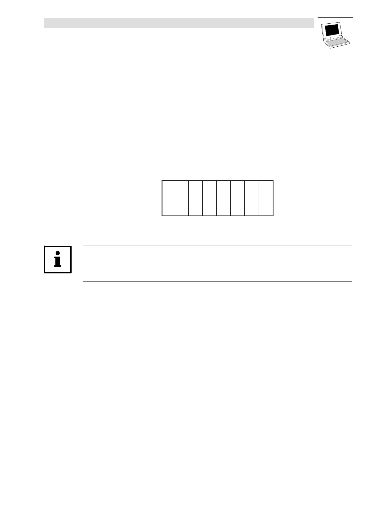
The system−block principle can be explained by means of a PLC system in a rack:
The rack contains the CPU, digital I/Os, analog I/Os, counter card, positioning card, etc. as
additional cards:
Drive PLC
Preface and general information
CPU
The CPU can directly access the additional cards and process the resulting information.
Additional cards have fixed addresses for access.
With Lenze PLC controllers, system blocks can be compared with these additional cards!
System blocks are special (hardware) function blocks permanently integrated into the
run−time system of the PLC.
SBs can address real hardware.
SBs are assigned/identified through so−called node numbers. (^ 1−4)
SB inputs and outputs are accessed via system variables or absolute memory addresses.
(^ 1−5)
Inputs/outputs are always classified from the program’s point of view. (^ 1−6)
Required SBs must be explicitly linked to the project via the control configuration of DDS.
(^ 1−7)
xxxxxx
x = Additional cards
l
DrivePLC DE 6.0
1−3
Page 10
Drive PLC
Preface and general information
1.2.2 Node numbers
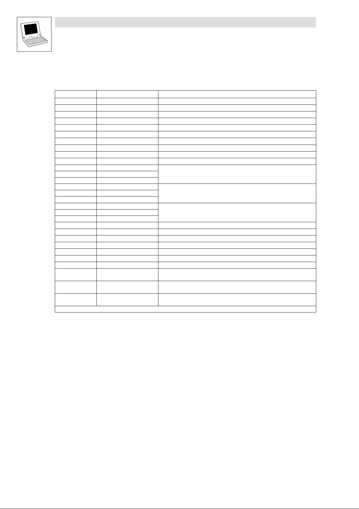
The system blocks of the Drive PLC carry the following node numbers:
Node number System block Notes
1 DIGITAL_IO Digital inputs/outputs
2 DIGITAL_IO_EB1 Digital inputs/outputs, internal extension module Extension board 1
3 DIGITAL_IO_EB2 Digital inputs/outputs, internal extension module Extension board 2
4 DIGITAL_IO_EB3 Digital inputs/outputs, internal extension module Extension board 3
11 ANALOG1_IO Analog inputs/outputs 1
12 ANALOG2_IO Analog input 2
13 ANALOG3_IO Analog input 3
14 ANALOG4_IO_EB3 Analog input 4, internal extension module Extension board 3
15 ANALOG5_IO_EB3 Analog input 5, internal extension module Extension board 3
21 DFIN_IO_DigitalFrequency Encoder input, internal extension module Extension board 3
31 CAN1_IO
32 CAN2_IO
33 CAN3_IO
34 FIF_CAN1_IO
35 FIF_CAN2_IO
36 FIF_CAN3_IO
41 AIF1_IO_AutomationInterface
42 AIF2_IO_AutomationInterface
43 AIF3_IO_AutomationInterface
101 CAN_Management System bus (CAN) management
102 CAN_Synchronization System bus (CAN) synchronisation
111 FIF_CAN_Management System bus (CAN) management, CAN−I/O1 FIF module
141 FCODE_FreeCodes Free codes
150 AD_Channels AD channels (24 V supply voltage)
151 SYSTEM_FLAGS System flags
161 AIF_IO_Management Automation interface management
200 DIGITAL_IO_FIF Digital inputs/outputs, Standard I/O
201 ANALOG_IO_FIF Analog inputs/outputs, Standard I/O
202 FIF_CAN_DIGITAL_IN Digital input, CAN−I/O
1
SBs for system bus (CAN) are described in the System bus (CAN) for Lenze PLCs Manual.
The node number is part of an absolute SB address (see chapter 1.2.4). (^ 1−5)
System bus (CAN)
System bus (CAN), CAN−I/O1FIF module
Automation interface
FIF module
FIF module
FIF module
1
1
1
1−4
DrivePLC DE 6.0
l
Page 11
1.2.3 Access via system variables
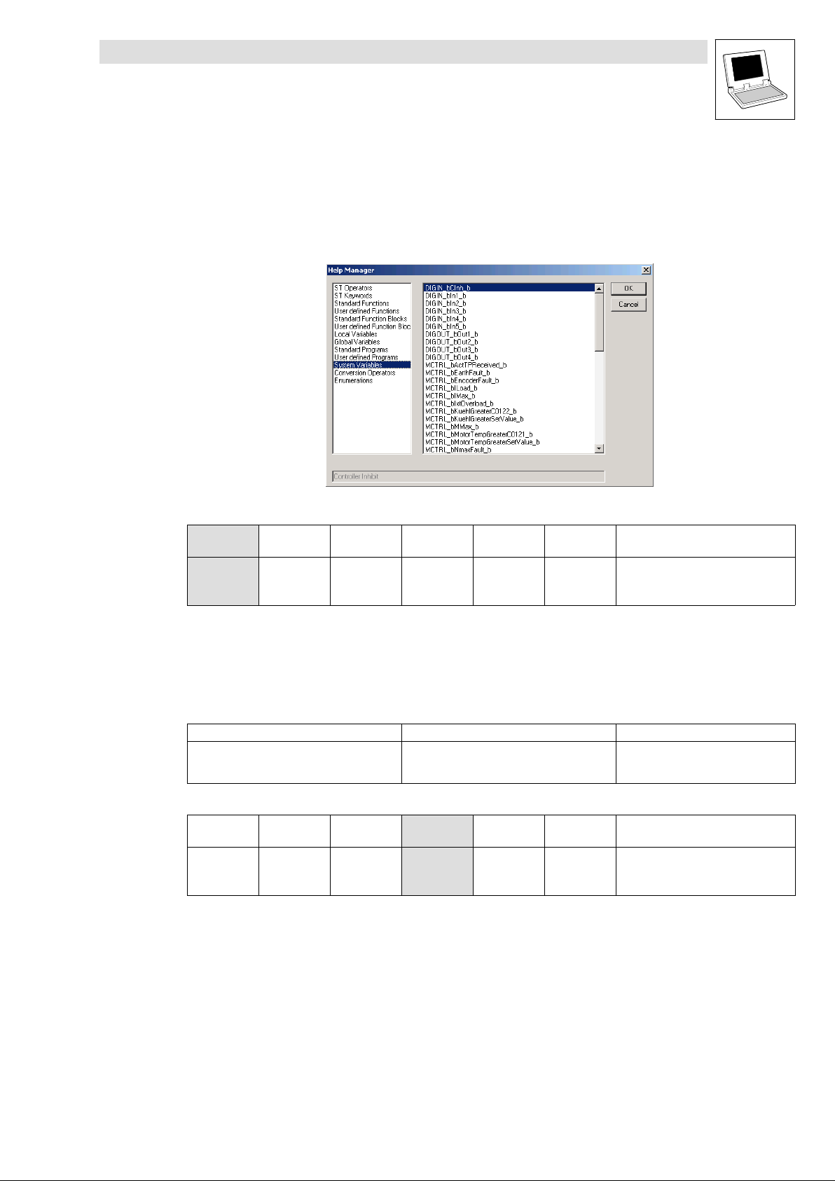
You can use the system variables of a system block in your project after the system block has been
integrated into the control configuration of the DDS.
Open the input assistance in the DDS editors via <F2> to get a listing of all available system
variables:
Drive PLC
Preface and general information
This Manual lists the system variables in the table for the corresponding system block:
Variable Data type Signal type Address Display
DIGIN_bIn1_b
... ... ...
DIGIN_bIn8_b %IX1.0.7 C0443/8
Example: Table with SB DIGITAL_IO inputs of the Drive PLC
Bool Binary
%IX1.0.0 C0443/1
1.2.4 Access via absolute addresses
System block inputs and outputs can also be accessed via absolute addresses according to the
IEC61131−3 standard:
For inputs use: For outputs use:
%IXa.b.c %QXa.b.c
This Manual lists the absolute addresses in the table for the corresponding system block:
Variable Data type Signal type Address Display
DIGIN_bIn1_b
... ... ...
DIGIN_bIn8_b %IX1.0.7 C0443/8
Example: Table with SB DIGITAL_IO inputs of the Drive PLC
Bool Binary
%IX1.0.0 C0443/1
code
code
Display
format
bin
Display
format
bin
Note
a = node number
b = word address
c = bit address
Note
l
DrivePLC DE 6.0
1−5
Page 12
Drive PLC
Preface and general information
1.2.5 Definition of inputs/outputs
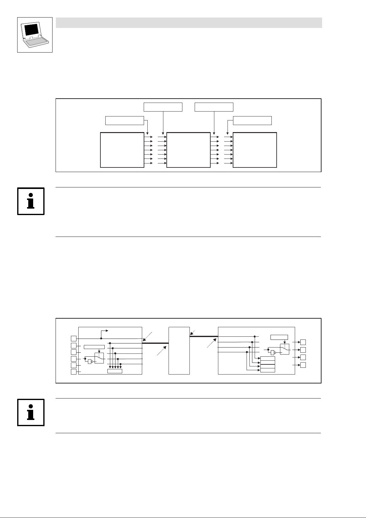
The application program is connected with the hardware by linking system blocks with program
organisation units (POUs):
SB-Output SB-Input
POU-Input POU-Output
SB
POU
Fig. 1−1 Principle: Linking of system blocks with a program organisation unit (POU)
Tip!
Inputs and outputs are always classified from the program’s point of view.
Logic SB inputs are hardware outputs of the PLC.
Logic SB outputs are hardware inputs of the PLC.
Example: System block DIGITAL_IO of the 9300 Servo PLC
If you want to use the digital input 1 and the digital output 1 of the 9300 Servo PLC, proceed as
follows:
1. Link the SB DIGITAL_IO explicitly with the DDS control configuration.
2. Access to digital input 1:
Assign the system variable DIGIN_bIn1_b to a POU input.
3. Access to digital output 1:
Assign the system variable DIGOUT_bOut1_b to a POU output.
POU
POU-OUT
SB-IN
SB-OUT
POU-IN
0
1
DCTRL -X5/28
DIGIN_bCInh_b
DIGIN_bIn1_b
DIGIN_bIn2_b
DIGIN_bIn3_b
DIGIN_bIn4_b
DIGIN_bIn5_b
C0443
DIGIN
X5
28
E1
C0114/1...5
E2
E3
1
E4
E5
DIGOUT_bOut1_b
DIGOUT_bOut2_b
DIGOUT_bOut3_b
DIGOUT_bOut4_b
SB
(^ 1−7)
C0444/1
C0444/2
C0444/3
C0444/4
DIGOUT
C0118/1...4
0
1
1
X5
A1
A2
A3
A4
Fig. 1−2 Principle: Linking of the 9300 Servo PLC system block DIGITAL_IO with a POU
Tip!
According to the IEC61131−3 standard, only one copy of the digital input 1 and the digital output 1
may be transferred.
1−6
DrivePLC DE 6.0
l
Page 13
1.2.6 Linking of system blocks with DDS
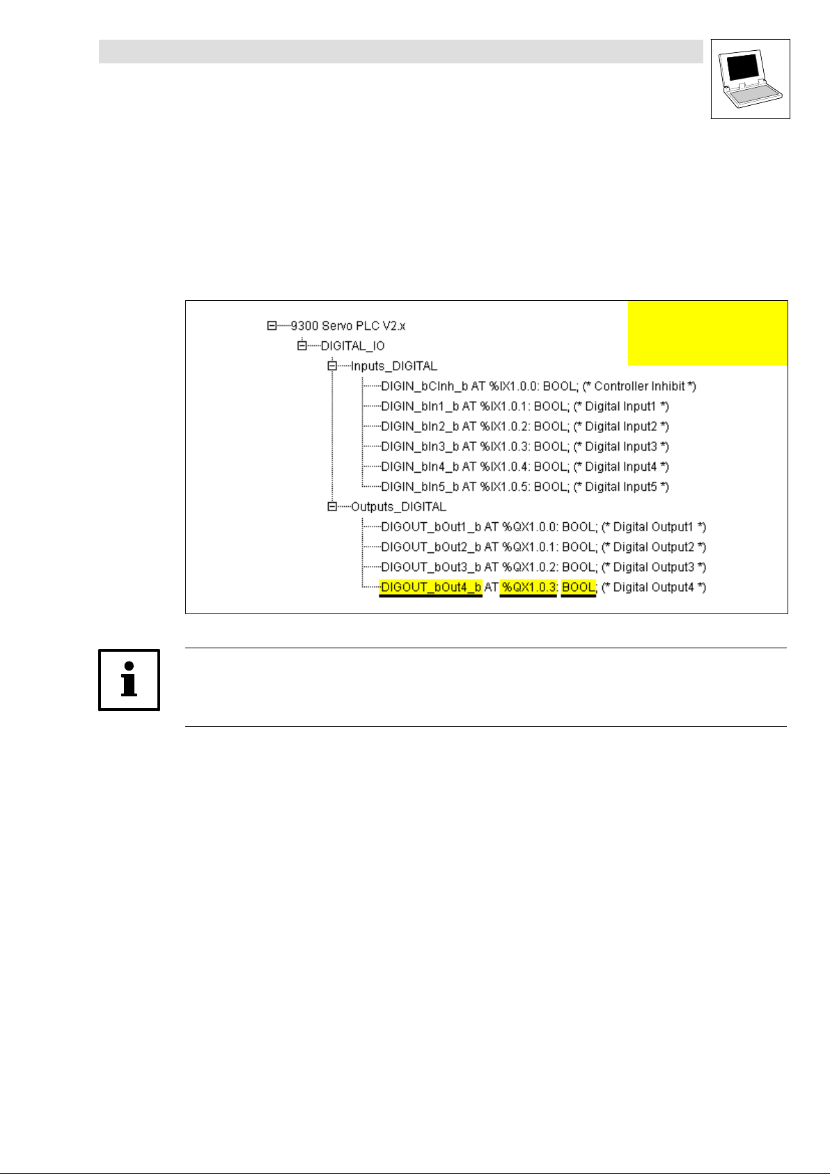
The system blocks required must be explicitly linked to the project via the control configuration of the
DDS.
The control configuration is placed as an object in the Resources tab in the Object organiser.
The control configuration lists all inputs and outputs including the identifiers of the
corresponding I/O variable, the absolute address and the data type of the I/O variable for
every linked SB.
Drive PLC
Preface and general information
Identifier of the I/O variable
Absolute address
Data type of the I/O variable
Fig. 1−3 Example: Control configuration for 9300 Servo PLC with linked SB DIGITAL_IO
Tip!
The control configuration provides a context menu for adding and deleting SBs which can be
activated via the right mouse key.
l
DrivePLC DE 6.0
1−7
Page 14
Drive PLC
Preface and general information
1.2.7 Signal types and scalings
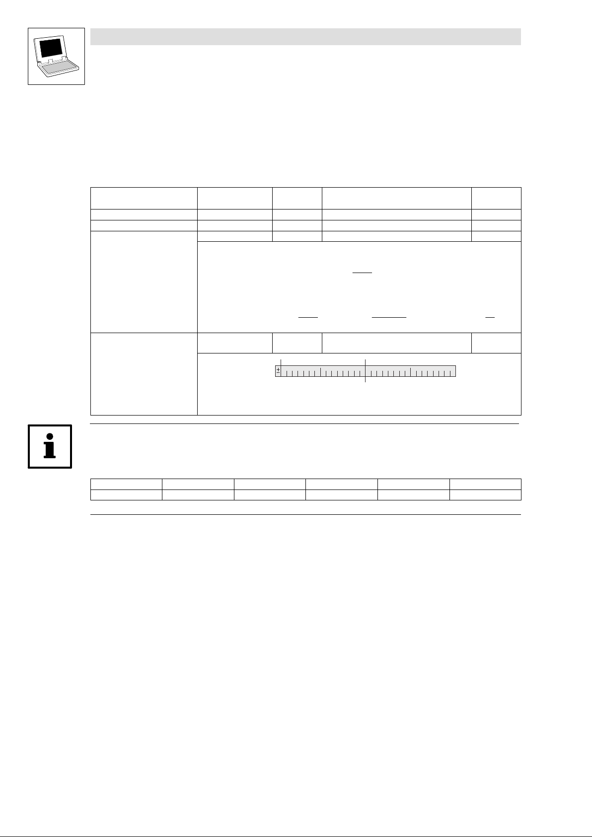
Most inputs and outputs of Lenze function blocks/system blocks can be assigned to a certain signal
type. We distinguish between digital, analog, position and speed signals.
The identifier of the corresponding input/output variable has an ending (starting with an underscore).
It indicates the signal type.
Signal type Ending Memory
Analog _a (analog) 16 bits 100 % 16384 H
Digital _b (binary) 8 bits 0 FALSE; 1 TRUE G
Phase difference or speed
Phase−angle or position _p (position) 32 bits 1 motor revolution 65536 E
_v (velocity) 16 bits 15000 rpm 16384 F
Phase difference/speed ref. to 1 ms
Scaling example:
Speed (on motor side) + 15000 [rpm] +
1 motor revolution + 65536 [inc]
Variable value (..._v) +
space
Direction (0 clockwise rotation; 1 counter−clockwise rotation)
No. of motor revolutions (0 ... 32767)
Phase angle or position (0 ... 65535)
Scaling
(external value º internal value)
15000
60 [s]
15000
@ 65536 [inc] +
60 [s]
High Word Low Word 031
15000
60000 [ms]
@ 65536 [inc] + 16384
Previous
identification
inc
ƪ
ƫ
ms
Note!
Due to their scaling, analog signals have an asymmetrical resolution range (−200 % ... +199.99 %):
External value: −200 % −100 % 0 +100 % +199.99 %
Internal value: −32768 −16384 0 +16384 +32767
1−8
DrivePLC DE 6.0
l
Page 15

2 System blocks
The following sections inform about the system blocks of the basic unit.
Drive PLC
System blocks
L
DrivePLC DE 6.0
2−1
Page 16
Drive PLC
System blocks
2.1 AD_CHANNELS
2.1 AD_CHANNELS
2.1.1 Inputs_AD_CHANNELS
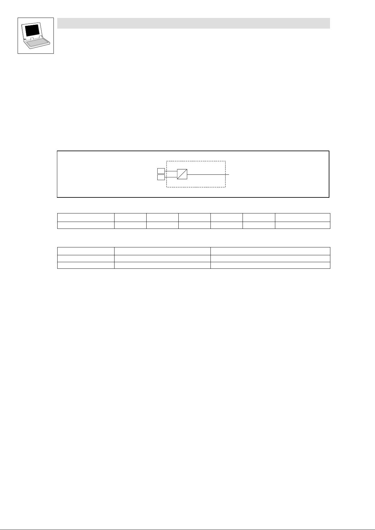
A/D conversion of 24 V voltage supply (node number 150)
This SB indicates the voltage of terminals X1/+24,
If 24 V
(100 mV
Fig. 2−1 AD_Channels
VariableName
V24PowerSupply Integer − %IW150.0 − − 1 100 mV
Electrical data of the input terminal
Terminal Use Data
+24 Supply voltage Level: + 18 VDC ... +30 V
24 Supply voltage reference potential
24 as integer value with a resolution of 100 mV.
is applied to the terminals, the V24PowerSupply has the value "240"
DC
240 = 24 V).
X1
+24
^24
DataType SignalType Address DIS DIS format Note
AD_CHANNELS
A
D
V24PowerSupply
DC
2−2
DrivePLC DE 6.0
L
Page 17
Drive PLC
System blocks
2.2 AIF1_IO_AutomationInterface (node number 41)
2.2 AIF1_IO_AutomationInterface (node number 41)
2.2.1 Inputs_AIF1
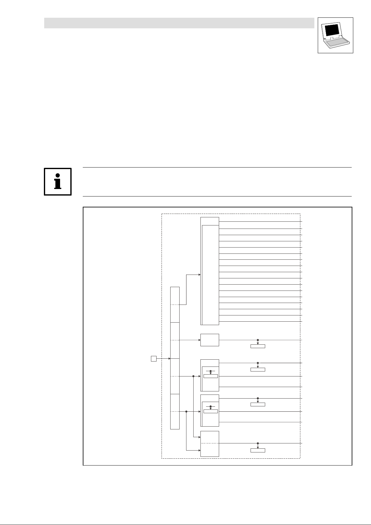
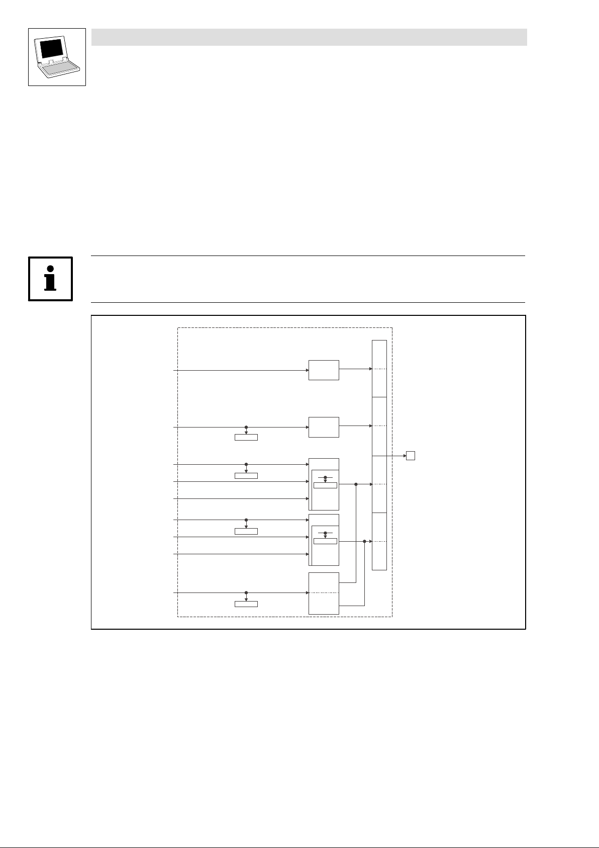
This SB is used as interface for input signals (e.g. setpoints/actual values) from attached fieldbus
modules (e.g. INTERBUS, PROFIBUS−DP).
The process image is
– created every 10 ms.
– created in an interval task within the time set for this task.
– read at the beginning of the task and written at its end.
Tip!
Please observe the Operating Instructions for the attached fieldbus module.
Automation
Interface
Inputs_AIF1
Byte
1
Controlword
Byte
2
Byte
3
Byte
4
Byte
5
Byte
6
Byte
7
Byte
8
16 Bit
16 binary
signals
16 Bit
16 Bit
C0855/1
16 binary
signals
16 Bit
C0855/2
16 binary
signals
C0856/1
C0856/2
C0856/3
AIF1_wDctrlCtrl
AIF1_bCtrlB0_b
AIF1_bCtrlB1_b
AIF1_bCtrlB2_b
AIF1_bCtrlQuickstop_b
AIF1_bCtrlB4_b
AIF1_bCtrlB5_b
AIF1_bCtrlB6_b
AIF1_bCtrlB7_b
AIF1_bCtrlDisable_b
AIF1_bCtrlCInhibit_b
AIF1_bCtrlTripSet_b
AIF1_bCtrlTripReset_b
AIF1_bCtrlB12_b
AIF1_bCtrlB13_b
AIF1_bCtrlB14_b
AIF1_bCtrlB15_b
AIF1_nInW1_a
AIF1_nInW2_a
AIF1_bInB0_b
…
AIF1_bInB15_b
AIF1_nInW3_a
AIF1_bIn16_b
…
AIF1_bIn31_b
Fig. 2−2 Inputs_AIF1
L
16 Bit
LowWord
16 Bit
HighWord
DrivePLC DE 6.0
AIF1_dnInD1_p
C0857
2−3
Page 18
Drive PLC
System blocks
2.2 AIF1_IO_AutomationInterface (node number 41)
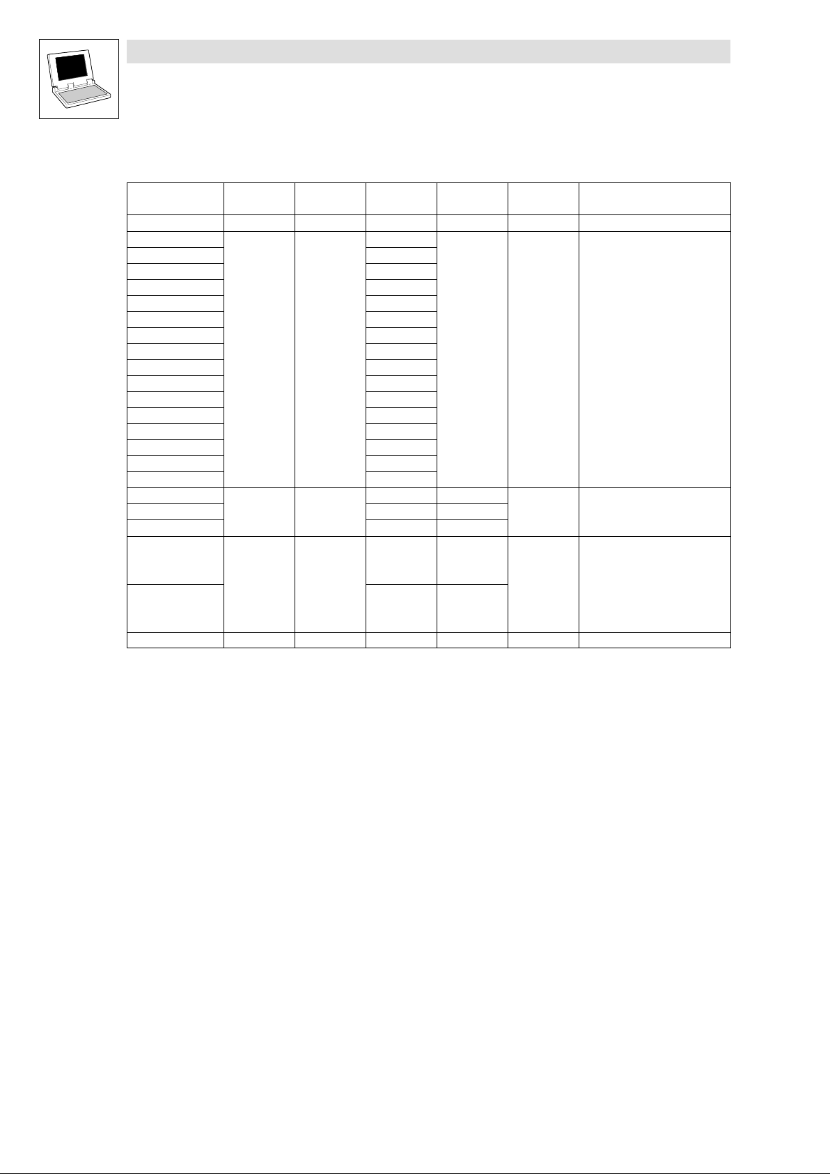
System variables
Variable Data type Signal type Address Display
AIF1_wDctrlCtrl WORD − %IX41.0 C0136/3 hex
AIF1_bCtrlB0_b
AIF1_bCtrlB1_b
AIF1_bCtrlB2_b
AIF1_bCtrlQuickstop_b
AIF1_bCtrlB4_b
AIF1_bCtrlB5_b
AIF1_bCtrlB6_b
AIF1_bCtrlB7_b
AIF1_bCtrlDisable_b
AIF1_bCtrlCInhibit_b
AIF1_bCtrlTripSet_b
AIF1_bCtrlTripReset_b
AIF1_bCtrlB12_b
AIF1_bCtrlB13_b
AIF1_bCtrlB14_b
AIF1_bCtrlB15_b
AIF1_nInW1_a
AIF1_nInW2_a
AIF1_nInW3_a
AIF1_bInB0_b
...
AIF1_bInB15_b
AIF1_bInB16_b
...
AIF1_bInB31_b
AIF1_dnInD1_p Double integer position %ID41.1 C0857 dec [inc]
Bool binary
Integer analog
Bool binary
%IX41.0.0
%IX41.0.1
%IX41.0.2
%IX41.0.3
%IX41.0.4
%IX41.0.5
%IX41.0.6
%IX41.0.7
%IX41.0.8
%IX41.0.9
%IX41.0.10
%IX41.0.11
%IX41.0.12
%IX41.0.13
%IX41.0.14
%IX41.0.15
%IW41.1 C0856/1
%IW41.2 C0856/2
%IW41.3 C0856/3
%IX41.2.0
...
%IX41.2.15
%IX41.3.0
...
%IX41.3.15
code
C0136/3 bin
C0855/1
C0855/2
Display
format
dec [%]
hex
Notes
2−4
DrivePLC DE 6.0
L
Page 19
Drive PLC
System blocks
2.2 AIF1_IO_AutomationInterface (node number 41)
User data
The received 8 bytes of user data are assigned to several variables of different data types. Data can
therefore be evaluated as —
binary information (1 bit)
control word/quasi−analog value (16 bits)
angle information (32 bits)
in the PLC program.
Byte Variable (1 bit) Variable (16 bits) Variable (32 bits)
1, 2 AIF1_bInB0_b
3, 4
AIF1_bInB1_b
AIF1_bInB2_b
AIF1_bCtrlQuickstop_b
AIF1_bInB4_b
...
AIF1_bInB7_b
AIF1_bCtrlDisable_b
AIF1_bCtrlCInhibit_b
AIF1_bCtrlTripSet_b
AIF1_bCtrlTripReset_b
AIF1_bInB12_b
...
AIF1_bInB15_b
AIF1_wDctrlCtrl
AIF1_nInW1_a
5, 6 AIF1_bInB0_b
...
AIF1_bInB15_b
7, 8 AIF1_bInB16_b
...
AIF1_bInB31_b
AIF1_nInW2_a
AIF1_dnInD1_p
AIF1_nInW3_a
Tip!
Drive PLC:
All variables assigned to byte 1/2 can be freely used in the PLC program.
9300 Servo PLC:
In addition to signals such as IMP and CINH, the SB status word DCTRL contains some freely
assignable signals which can be overwritten via the variables DCTRL_bStateB..._b of the
SB DCTRL. More detailed information about the SB DCTRL can be found in the
"9300 Servo PLC" Online Manual.
The control signals for the quick stop (QSP), DISABLE, CINH, TRIP−SET and TRIP−RESET
function can also be read and processed via the following variables:
– AIF1_bCtrlQuickstop_b
– AIF1_bCtrlDisable_b
– AIF1_bCtrlInhibit_b
– AIF1_bCtrlTripSet_b
– AIF1_bCtrlTripReset_b
The remaining 11 bits (AIF1_bCtrlB..._b) can be used to control additional functions/function
blocks.
L
DrivePLC DE 6.0
2−5
Page 20
Drive PLC
System blocks
2.2 AIF1_IO_AutomationInterface (node number 41)
2.2.2 Outputs_AIF1
This SB is used as interface for output signals (e.g. setpoints/actual values) to attached fieldbus
modules (e.g. INTERBUS, PROFIBUS−DP).
The process image is
– created every 10 ms.
– created in an interval task within the time set for this task.
– read at the beginning of the task and written at its end.
Tip!
Please observe the Operating Instructions for the attached fieldbus module.
Outputs_AIF1
Fig. 2−3 Outputs_AIF1
AIF1_wDctrlStat
AIF1_nOutW1_a
AIF1_nOutW2__a
AIF1_bFDO0_b
…
AIF1_bFDO15_b
AIF1_nOutW3_a
AIF1_bFDO16_b
…
AIF1_bFDO31_b
AIF1_dnOutD1_p
C0858/1
C0858/2
C0858/3
C0859
16 Bit
16 Bit
16 Bit
C0151/4
16 binary
signals
16 Bit
C0151/4
16 binary
signals
16 Bit
LowWord
16 Bit
HighWord
Byte
Byte
Byte
Byte
Byte
Byte
Byte
Byte
1
2
3
4
5
6
7
8
Automation
Interface
2−6
DrivePLC DE 6.0
L
Page 21
Drive PLC
System blocks
2.2 AIF1_IO_AutomationInterface (node number 41)
System variables
Variable Data type Signal type Address Display
AIF1_wDctrlStat WORD − %QW41.0 − −
AIF1_nOutW1_a
AIF1_nOutW2_a %QW41.2 C0858/2
AIF1_nOutW3_a %QW41.3 C0858/3
AIF1_bFDO0_b
.. ...
AIF1_bFDO15_b %QX41.2.15
AIF1_bFDO16_b %QX41.3.0
.. ...
AIF1_bFDO31_b %QX41.3.15
AIF1_dnOutD1_p Double integer position %QD41.1 C0859 dec [inc]
Integer analog
Bool binary
%QW41.1 C0858/1
%QX41.2.0
code
C0151/4 hex
Display
format
dec [%]
Notes
Display code in hex
as double word
User data
The 8 bytes of user data to be sent can be written via several variables of different data types at the
same time. Data can therefore be transferred as
binary information (1 bit)
status word/quasi−analog value (16 bits)
angle information (32 bits)
by the PLC program.
Byte Variable (1 bit) Variable (16 bits) Variable (32 bits)
1, 2
3, 4
5, 6 AIF1_bFDO0_b
...
AIF1_bFDO15_b
7, 8 AIF1_bFDO16_b
...
AIF1_bFDO31_b
AIF1_wDctrlStat
AIF1_nOutW1_a
AIF1_nOutW2_a
AIF1_dnOutD1_p
AIF1_nOutW3_a
Tip!
Drive PLC:
All variables assigned to byte 1/2 can be freely used in the PLC program.
9300 Servo PLC:
Connect the variable DCTRL_wStat of the SB DCTRL with the variable AIF1_wDctrlStat to
transfer the status word of the SB DCTRL via user data bytes 1 and 2.
In addition to signals such as IMP and CINH, the SB status word DCTRL contains some freely
assignable signals which can be overwritten via the variables DCTRL_bStateB..._b of the
SB DCTRL. More detailed information about the SB DCTRL can be found in the
"9300 Servo PLC" Online Manual.
L
DrivePLC DE 6.0
2−7
Page 22
Drive PLC
System blocks
2.2 AIF1_IO_AutomationInterface (node number 41)
Tip!
Avoid simultaneous overwriting via different variable types to ensure data consistency.
Thus bytes 5 and 6 should only be overwritten
– by the variable AIF1_dnOutD1_p,
– by the variable AIF1_nOutW2_a or
– by the variables AIF1_bFDO0_b ... AIF1_bFDO15_b.
2−8
DrivePLC DE 6.0
L
Page 23
Drive PLC
System blocks
2.3 AIF2_IO_AutomationInterface (node number 42)
2.3 AIF2_IO_AutomationInterface (node number 42)
2.3.1 Inputs_AIF2
Automation interface (node number 42)
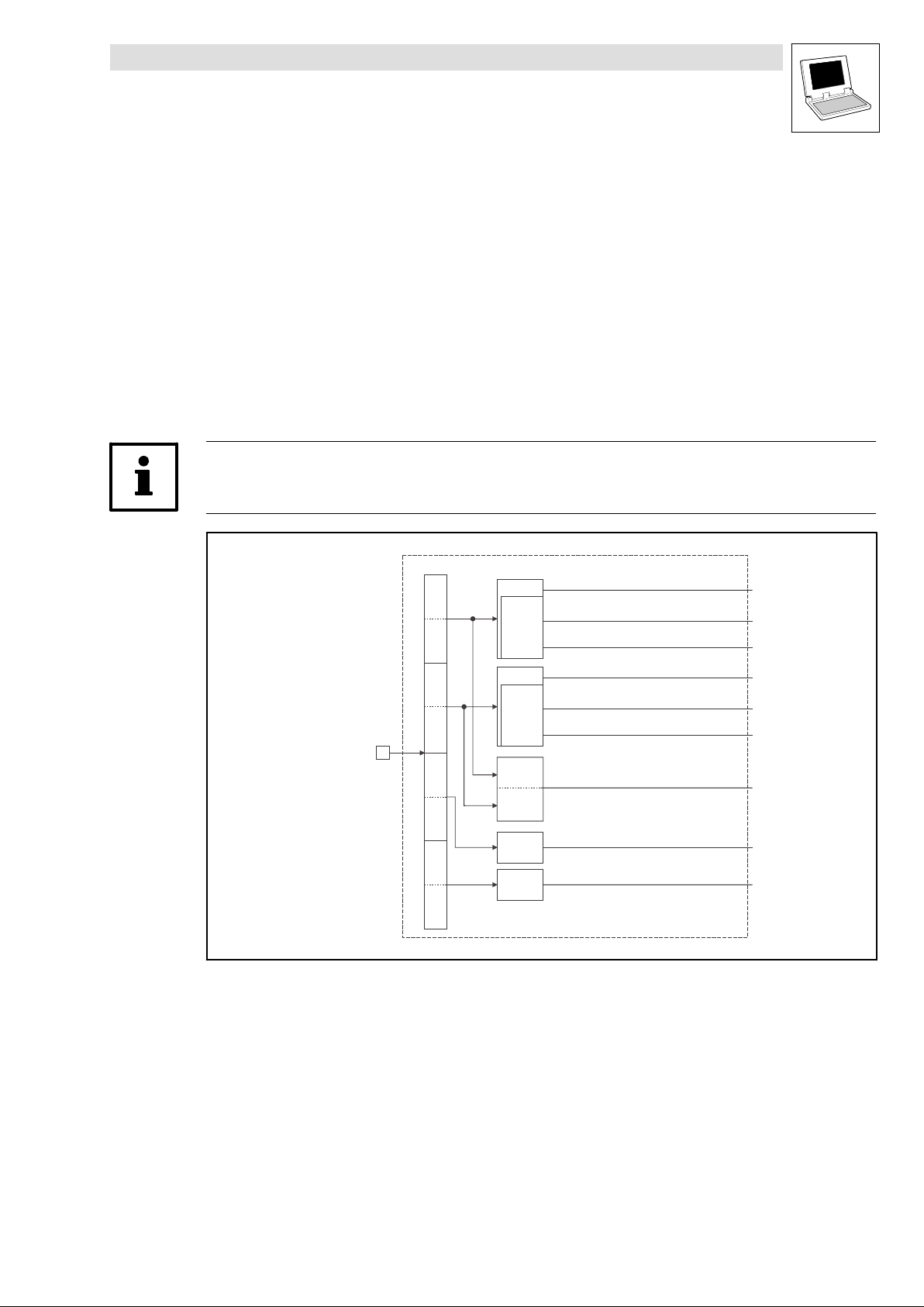
This SB is used as an interface for input signals (e.g. setpoints/actual values) from attached fieldbus
modules (e.g. INTERBUS, PROFIBUS−DP).
The process image is
– created in the cyclic task in a fixed time interval of 10 ms.
– created in an interval task within the time set for this task.
– read at the beginning of the task and written at its end.
Tip!
Please observe the Operating Instructions for the attached fieldbus module.
Fig. 2−4 Inputs_AIF2
Automation
Interface
Inputs_AIF2
Byte
1
Byte
2
Byte
3
Byte
4
Byte
5
Byte
6
Byte
7
Byte
8
16 Bit
16 binary
signals
16 Bit
16 binary
signals
16 Bit
LowWord
16 Bit
HighWord
16 Bit
16 Bit
AIF2_nInW1_a
AIF2_bInB0_b
...
AIF2_bInB15_b
AIF2_nInW2_a
AIF2_bInB16_b
...
AIF2_bInB31_b
AIF2_dnInD1_p
AIF2_nInW3_a
AIF2_nInW4_a
L
DrivePLC DE 6.0
2−9
Page 24
Drive PLC
System blocks
2.3 AIF2_IO_AutomationInterface (node number 42)
System variables
Variable Data type Signal type Address Display code Display
AIF2_nInW1_a
AIF2_nInW2_a %IW42.1
AIF2_nInW3_a %IW42.2
AIF2_nInW4_a %IW42.3
AIF2_bInB0_b
... ...
AIF2_bInB15_b %IX42.0.15
AIF2_bInB16_b %IX42.1.0
... ...
AIF2_bInB31_b %IX42.1.15
AIF2_dnInD1_p Double integer Position %ID42.0
Integer Analog
Bool Binary
%IW42.0
%IX42.0.0
format
Note
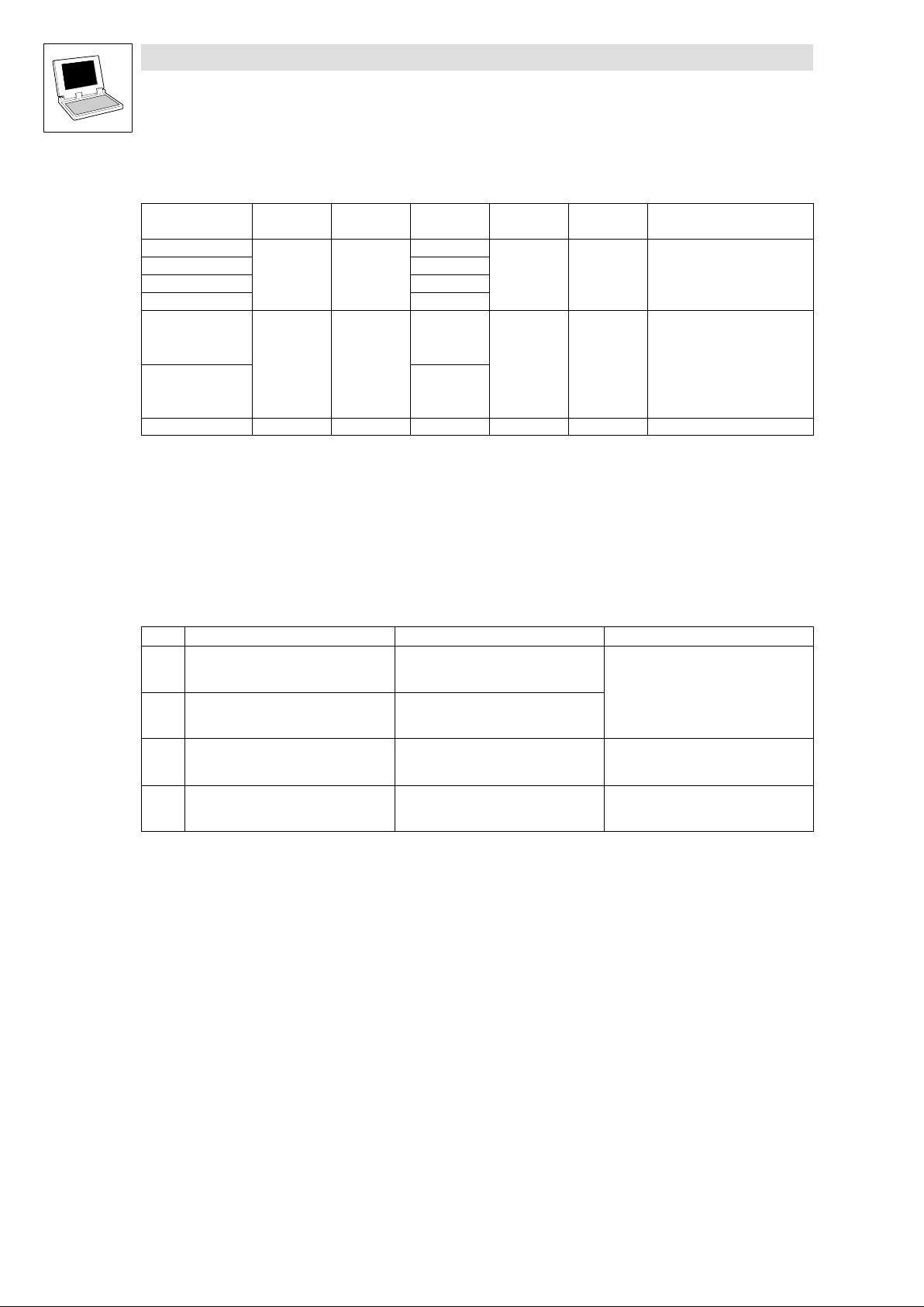
User data
The 4 first bytes of the received 8 bytes of user data are assigned to several variables of different data
types simultaneously. Thus the data can be evaluated in the PLC program as
binary information (1 bit)
quasi−analog value (16 bits)
angle information (32 bits)
according to the requirements.
Byte Variable (1 bit) Variable (16 bits) Variable (32 bits)
1, 2 AIF2_bInB0_b
...
AIF2_bInB15_b
3, 4 AIF2_bInB16_b
...
AIF2_bInB31_b
5, 6
AIF2_nInW1_a
AIF2_dnInD1_p
AIF2_nInW2_a
AIF2_nInW3_a
7, 8
AIF2_nInW4_a
2−10
DrivePLC DE 6.0
L
Page 25
Drive PLC
System blocks
2.3 AIF2_IO_AutomationInterface (node number 42)
2.3.2 Outputs_AIF2
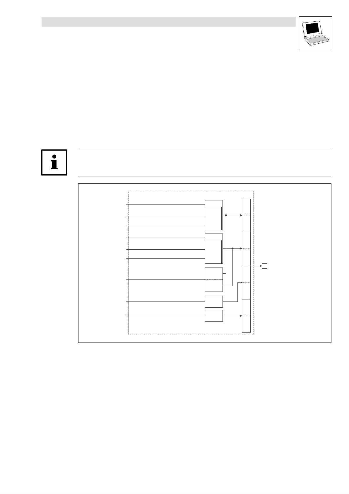
This SB is used as an interface for output signals (e.g. setpoints/actual values) to attached fieldbus
modules (e.g. INTERBUS, PROFIBUS−DP).
The process image is
– created in the cyclic task in a fixed time interval of 10 ms.
– created in an interval task within the time set for this task.
– read at the beginning of the task and written at its end.
Tip!
Please observe the Operating Instructions for the attached fieldbus module.
Outputs_AIF2
AIF2_nOutW1_a
AIF2_bFDO0_b
...
AIF2_bFDO15_b
AIF2_nOutW2_a
AIF2_bFDO16_b
...
AIF2_bFDO31_b
AIF2_dnOutD1_p
AIF2_nOutW3_a
AIF2_nOutW4_a
16 Bit
16 binary
signals
16 Bit
16 binary
signals
16 Bit
LowWord
16 Bit
HighWord
16 Bit
16 Bit
Byte
Byte
Byte
Byte
Byte
Byte
Byte
Byte
1
2
3
4
5
6
7
8
Automation
Interface
Fig. 2−5 Outputs_AIF2
L
DrivePLC DE 6.0
2−11
Page 26
Drive PLC
System blocks
2.3 AIF2_IO_AutomationInterface (node number 42)
System variables
Variable Data type Signal type Address Display code Display
AIF2_nOutW1_a
AIF2_nOutW2_a %QW42.1
AIF2_nOutW3_a %QW42.2
AIF2_nOutW4_a %QW42.3
AIF2_bFDO0_b
... ...
AIF2_bFDO15_b %QX42.0.15
AIF2_bFDO16_b %QX42.1.0
... ...
AIF2_bFDO31_b %QX42.1.15
AIF2_dnOutD1_p Double integer Position %QD42.0
Integer Analog
Bool Binary
%QW42.0
%QX42.0.0
format
Note
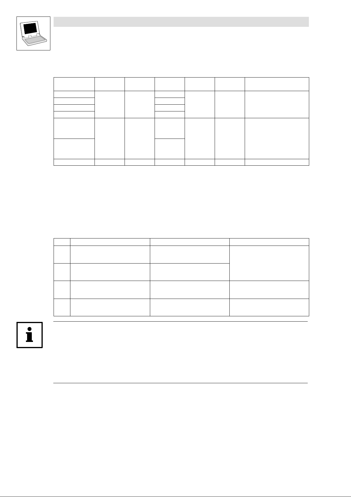
User data
The first 4 bytes of the 8 bytes of user data to be sent can be written to via several variables of different
data types at the same time. Data can therefore be transferred by the PLC program as
binary information (1 bit)
quasi−analog value (16 bits)
angle information (32 bits)
according to the requirements.
Byte Variable (1 bit) Variable (16 bits) Variable (32 bits)
1, 2 AIF2_bFDO0_b
...
AIF2_bFDO15_b
3, 4 AIF2_bFDO16_b
...
AIF2_bFDO31_b
5, 6
AIF2_nOutW1_a
AIF2_dnOutD1_p
AIF2_nOutW2_a
AIF2_nOutW3_a
7, 8
AIF2_nOutW4_a
Tip!
Avoid simultaneous overwriting via different variable types to ensure data consistency.
Thus bytes 1 and 2 should only be written to
– by the variable AIF2_dnOutD1_p,
– by the variable AIF2_nOutW1_a or
– by the variables AIF2_bFDO0_b ... AIF2_bFDO15_b.
2−12
DrivePLC DE 6.0
L
Page 27
Drive PLC
System blocks
2.4 AIF3_IO_AutomationInterface (node number 43)
2.4 AIF3_IO_AutomationInterface (node number 43)
2.4.1 Inputs_AIF3
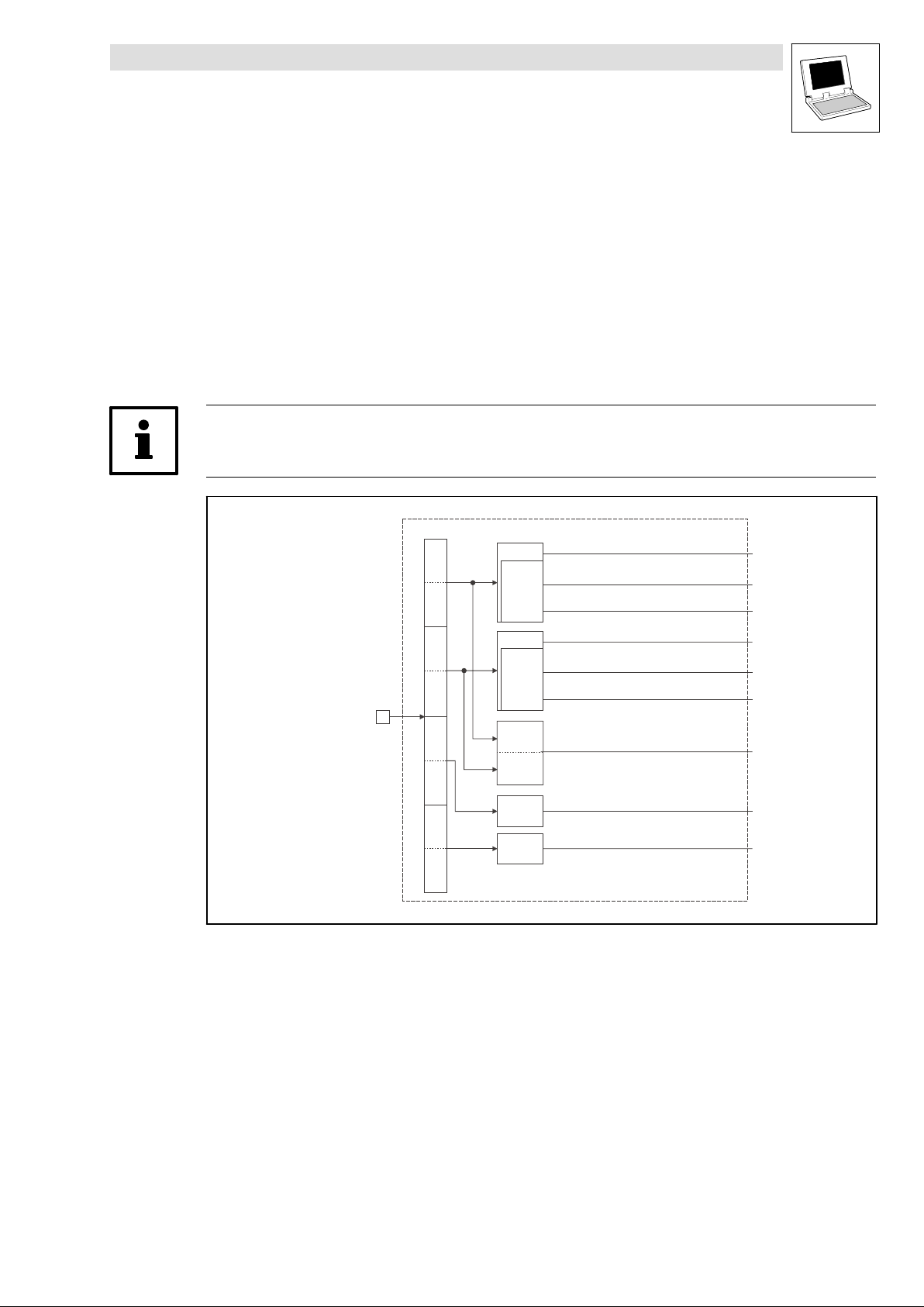
This SB is used as an interface for input signals (e.g. setpoints/actual values) from attached fieldbus
modules (e.g. INTERBUS, PROFIBUS−DP).
The process image is
– created in the cyclic task in a fixed time interval of 10 ms.
– created in an interval task within the time set for this task.
– read at the beginning of the task and written at its end.
Tip!
Please observe the Operating Instructions for the attached fieldbus module.
Fig. 2−6 Inputs_AIF3
Automation
Interface
Inputs_AIF3
Byte
1
Byte
2
Byte
3
Byte
4
Byte
5
Byte
6
Byte
7
Byte
8
16 Bit
16 binary
signals
16 Bit
16 binary
signals
16 Bit
LowWord
16 Bit
HighWord
16 Bit
16 Bit
AIF3_nInW1_a
AIF3_bInB0_b
...
AIF3_bInB15_b
AIF3_nInW2_a
AIF3_bInB16_b
...
AIF3_bInB31_b
AIF3_dnInD1_p
AIF3_nInW3_a
AIF3_nInW4_a
L
DrivePLC DE 6.0
2−13
Page 28
Drive PLC
System blocks
2.4 AIF3_IO_AutomationInterface (node number 43)
System variables
Variable Data type Signal type Address Display code Display
AIF3_nInW1_a
AIF3_nInW2_a %IW43.1
AIF3_nInW3_a %IW43.2
AIF3_nInW4_a %IW43.3
AIF3_bInB0_b
... ...
AIF3_bInB15_b %IX43.0.15
AIF3_bInB16_b %IX43.1.0
... ...
AIF3_bInB31_b %IX43.1.15
AIF3_dnInD1_p Double integer Position %ID43.0
Integer Analog
Bool Binary
%IW43.0
%IX43.0.0
format
Note
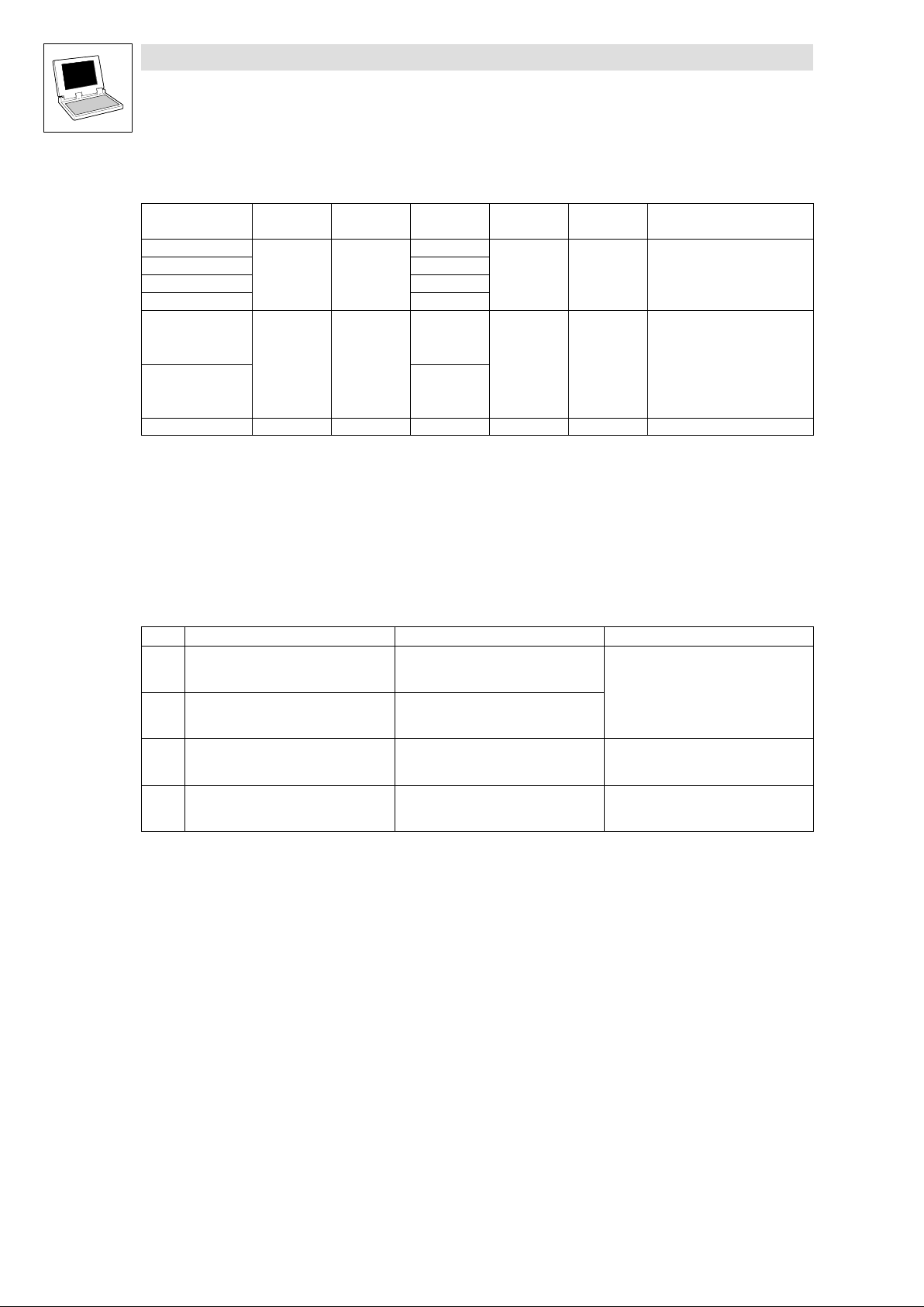
User data
The 4 first bytes of the received 8 bytes of user data are assigned to several variables of different data
types simultaneously. Thus the data can be evaluated in the PLC program as
binary information (1 bit)
quasi−analog value (16 bits)
angle information (32 bits)
according to the requirements.
Byte Variable (1 bit) Variable (16 bits) Variable (32 bits)
1, 2 AIF3_bInB0_b
...
AIF3_bInB15_b
3, 4 AIF3_bInB16_b
...
AIF3_bInB31_b
5, 6
AIF3_nInW1_a
AIF3_dnInD1_p
AIF3_nInW2_a
AIF3_nInW3_a
7, 8
AIF3_nInW4_a
2−14
DrivePLC DE 6.0
L
Page 29
Drive PLC
System blocks
2.4 AIF3_IO_AutomationInterface (node number 43)
2.4.2 Outputs_AIF3
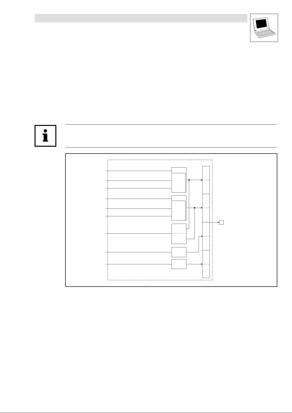
This SB is used as an interface for output signals (e.g. setpoints/actual values) to attached fieldbus
modules (e.g. INTERBUS, PROFIBUS−DP).
The process image is
– created in the cyclic task in a fixed time interval of 10 ms.
– created in an interval task within the time set for this task.
– read at the beginning of the task and written at its end.
Tip!
Please observe the Operating Instructions for the attached fieldbus module.
Outputs_AIF3
AIF3_nOutW1_a
AIF3_bFDO0_b
...
AIF3_bFDO15_b
AIF3_nOutW2_a
AIF3_bFDO16_b
...
AIF3_bFDO31_b
AIF3_dnOutD1_p
AIF3_nOutW3_a
AIF3_nOutW4_a
16 Bit
16 binary
signals
16 Bit
16 binary
signals
16 Bit
LowWord
16 Bit
HighWord
16 Bit
16 Bit
Byte
Byte
Byte
Byte
Byte
Byte
Byte
Byte
1
2
3
4
5
6
7
8
Automation
Interface
Fig. 2−7 Outputs_AIF3
L
DrivePLC DE 6.0
2−15
Page 30
Drive PLC
System blocks
2.4 AIF3_IO_AutomationInterface (node number 43)
System variables
Variable Data type Signal type Address Display code Display
AIF3_nOutW1_a
AIF3_nOutW2_a %QW43.1
AIF3_nOutW3_a %QW43.2
AIF3_nOutW4_a %QW43.3
AIF3_bFDO0_b
... ...
AIF3_bFDO15_b %QX43.0.15
AIF3_bFDO16_b %QX43.1.0
... ...
AIF3_bFDO31_b %QX43.1.15
AIF3_dnOutD1_p Double integer Position %QD43.0
Integer Analog
Bool Binary
%QW43.0
%QX43.0.0
format
Note
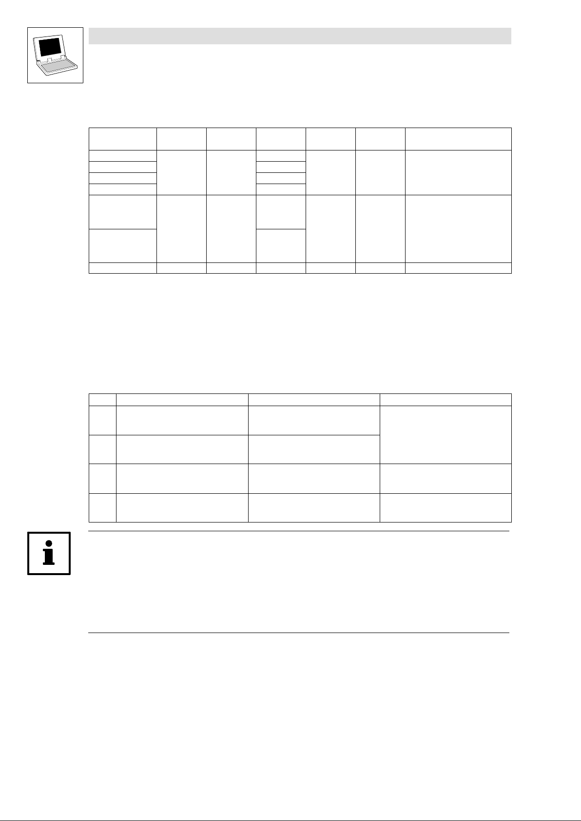
User data
The first 4 bytes of the 8 bytes of user data to be sent can be written to via several variables of different
data types at the same time. Data can therefore be transferred by the PLC program as
binary information (1 bit)
quasi−analog value (16 bits)
angle information (32 bits)
according to the requirements.
Byte Variable (1 bit) Variable (16 bits) Variable (32 bits)
1, 2 AIF3_bFDO0_b
...
AIF3_bFDO15_b
3, 4 AIF3_bFDO16_b
...
AIF3_bFDO31_b
5, 6
AIF3_nOutW1_a
AIF3_dnOutD1_p
AIF3_nOutW2_a
AIF3_nOutW3_a
7, 8
AIF3_nOutW4_a
Tip!
Avoid simultaneous overwriting via different variable types to ensure data consistency.
Thus bytes 1 and 2 should only be written to
– by the variable AIF3_dnOutD1_p,
– by the variable AIF3_nOutW1_a or
– by the variables AIF3_bFDO0_b ... AIF3_bFDO15_b.
2−16
DrivePLC DE 6.0
L
Page 31
Drive PLC
System blocks
2.5 AIF_IO_Management (node number 161)
2.5 AIF_IO_Management (node number 161)
2.5.1 Inputs_AIF_Management
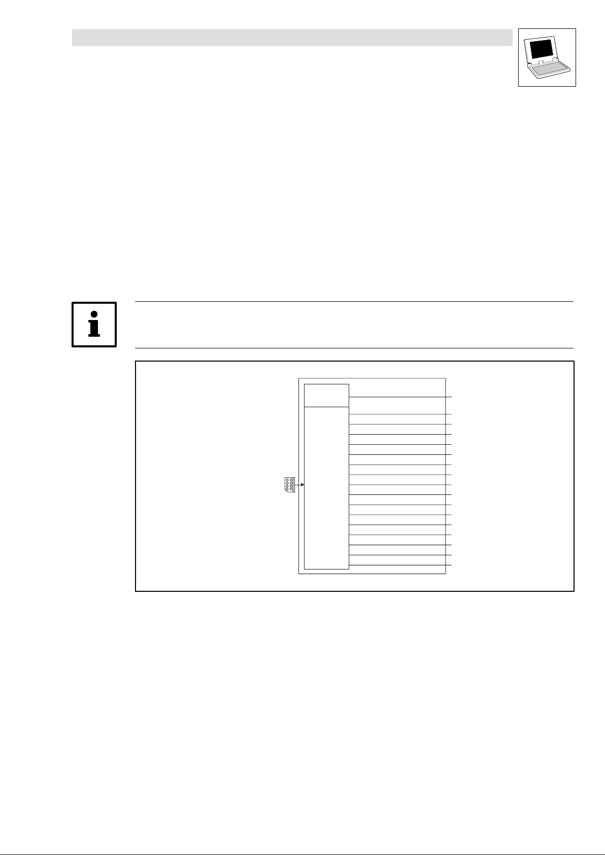
This SB monitors the communication of a communication module connected to the automation
interface (AIF).
In the event of an error, AIF_bCe0CommErr_b is set to TRUE and the communication error
"CE0" (LECOM no. 61) is set. The response to this can be configured under C0126 (Lenze
setting: off).
New AIF communication modules (e.g. 2133 and 2175) also use
AIF_bFieldBusStateBit0_b ... AIF_bFieldBusStateBit15_b to transfer an error number from the
communication module.
C2121 displays the status.
Tip!
Please observe the documentation for the attached communication module.
Automation
interface
Fig. 2−8 System block "Inputs_AIF_Management"
AIF
Communication
Error
AIF
Fieldbus State
Inputs_AIF_Management
AIF_bCe0CommErr_b
AIF_bFieldBusStateBit0_b
AIF_bFieldBusStateBit1_b
AIF_bFieldBusStateBit2_b
AIF_bFieldBusStateBit3_b
AIF_bFieldBusStateBit4_b
AIF_bFieldBusStateBit5_b
AIF_bFieldBusStateBit6_b
AIF_bFieldBusStateBit7_b
AIF_bFieldBusStateBit8_b
AIF_bFieldBusStateBit9_b
AIF_bFieldBusStateBit10_b
AIF_bFieldBusStateBit11_b
AIF_bFieldBusStateBit12_b
AIF_bFieldBusStateBit13_b
AIF_bFieldBusStateBit14_b
AIF_bFieldBusStateBit15_b
L
DrivePLC DE 6.0
2−17
Page 32
Drive PLC
System blocks
2.5 AIF_IO_Management (node number 161)
System variables
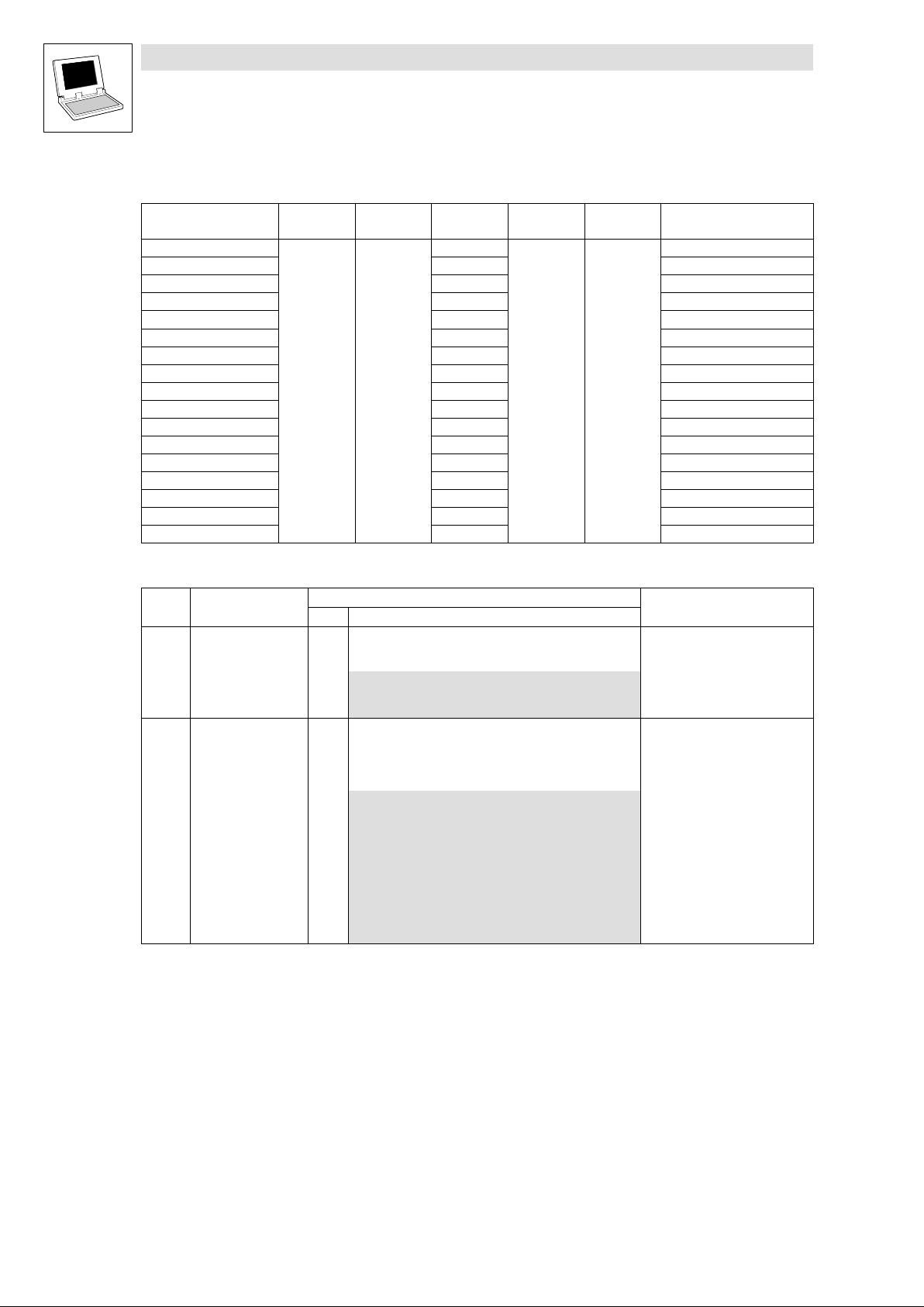
Variable Data type Signal type Address Display code Display
AIF_bCe0CommErr_b
AIF_bFieldBusStateBit0_b %IX161.1.0 Error number − bit 0
AIF_bFieldBusStateBit1_b %IX161.1.1 Error number − bit 1
AIF_bFieldBusStateBit2_b %IX161.1.2 Error number − bit 2
AIF_bFieldBusStateBit3_b %IX161.1.3 Error number − bit 3
AIF_bFieldBusStateBit4_b %IX161.1.4 Error number − bit 4
AIF_bFieldBusStateBit5_b %IX161.1.5 Error number − bit 5
AIF_bFieldBusStateBit6_b %IX161.1.6 Error number − bit 6
AIF_bFieldBusStateBit7_b %IX161.1.7 Error number − bit 7
AIF_bFieldBusStateBit8_b %IX161.1.8 Error number − bit 8
AIF_bFieldBusStateBit9_b %IX161.1.9 Error number − bit 9
AIF_bFieldBusStateBit10_b %IX161.1.10 Error number − bit 10
AIF_bFieldBusStateBit11_b %IX161.1.11 Error number − bit 11
AIF_bFieldBusStateBit12_b %IX161.1.12 Error number − bit 12
AIF_bFieldBusStateBit13_b %IX161.1.13 Error number − bit 13
AIF_bFieldBusStateBit14_b %IX161.1.14 Error number − bit 14
AIF_bFieldBusStateBit15_b %IX161.1.15 Error number − bit 15
Bool binary
%IX161.0.0 Communication error "CE0"
format
Notes
Codes
Code LCD
C0126 MONIT CE0 3
C2121 AIF: state
Possible settings
Lenze Selection
0 TRIP
2 Warning
3 Off
G
0 {dec} 255
Decimal value is bit−coded:
Bit 0 XCAN1_IN monitoring time
Bit 1 XCAN2_IN monitoring time
Bit 2 XCAN3_IN monitoring time
Bit 3 XCAN bus−off
Bit 4 XCAN operational
Bit 5 XCAN pre−operational
Bit 6 XCAN warning
Bit 7 Internally assigned
Info
Configuration for communication
error "CE0" with automation
interface
AIF−CAN: Status
Detailed information can be
found in the documentation for
the corresponding
communication module.
2−18
DrivePLC DE 6.0
L
Page 33
Drive PLC
System blocks
2.5 AIF_IO_Management (node number 161)
2.5.2 Outputs_AIF_Management
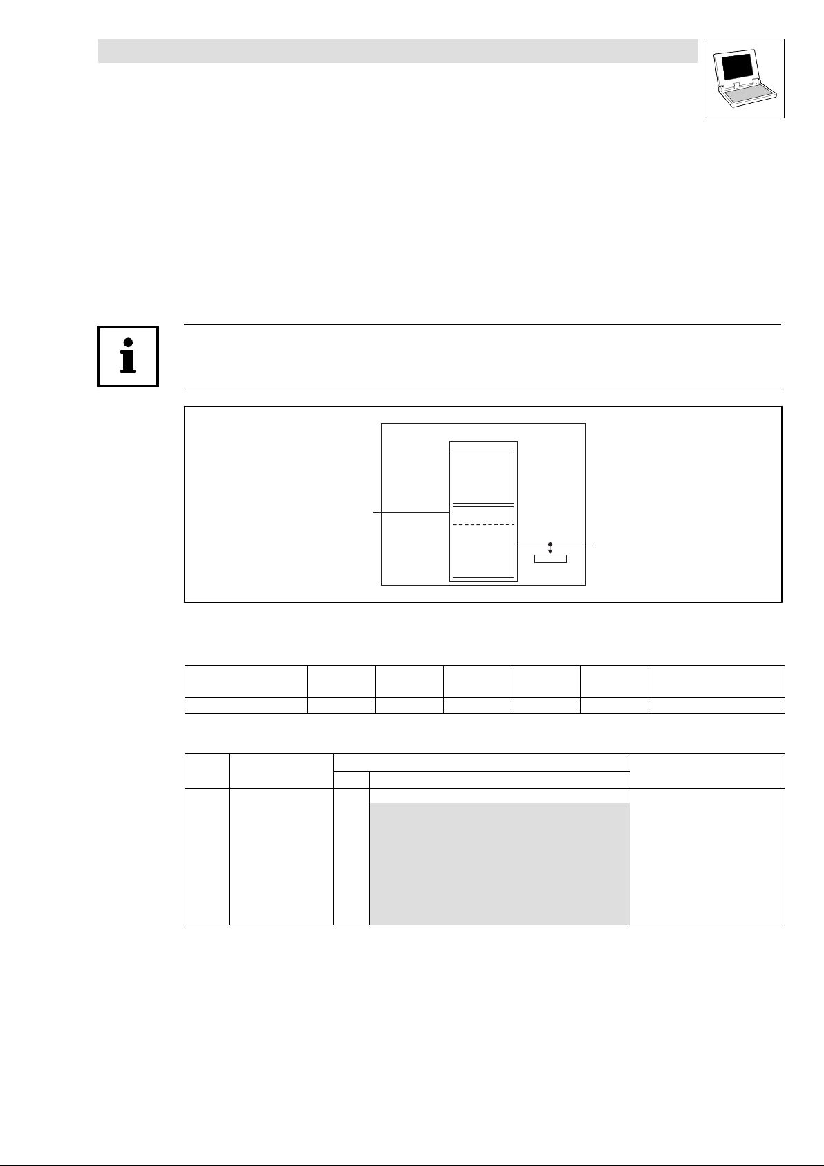
This SB transfers commands and messages to a fieldbus module connected to an automation
interface (AIF).
For this purpose C2120 provides a control word. The commands are specified as numbers. Some
command numbers are universally applicable for all fieldbus modules, others apply only for special
modules. The total number of commands available can amount to up to 16.
Tip!
Read the documentation for the attached fieldbus module.
Outputs_AIF_Management
AIF control word
Bit 8 … 15
AIF_wControl
Fig. 2−9 System block "Outputs_AIF_Management"
System variables
Variable Data type Signal type Address Display code Display
AIF_wControl Word %QX161.0 C2120
Codes
Code LCD
C2120 AIF: Control
Possible settings
Lenze Selection
0 No command
1 Read CAN codes + reinitialisation
2 Read XCAN codes
10 Read XCAN C2356/1 ... 4
11 Read XCAN C2357
12 Read XCAN C2375
13 Read XCAN C2376 ... C2378
14 Read XCAN C2382
255 Not assigned
Bit 7
Toggle-Bit (MSB)
Bit0…6
C2120
Note
format
Info
AIF command
L
DrivePLC DE 6.0
2−19
Page 34
Drive PLC
System blocks
2.6 ANALOG1_IO (node number 11)
2.6 ANALOG1_IO (node number 11)
2.6.1 Inputs_ANALOG1 (analog input)
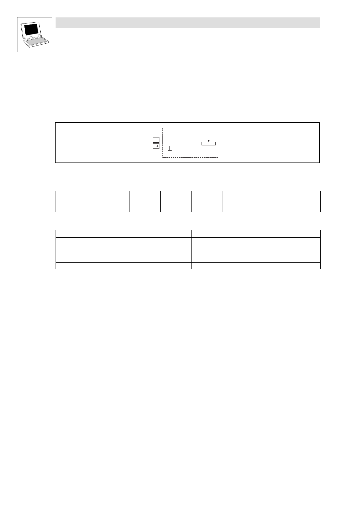
This SB forms the interface for analog signals via terminal AI1, A as setpoint input or actual value
input.
Fig. 2−10 Inputs_ANALOG1
System variables
Variable Data type Signal type Address Display
AIN1_nIn_a Integer analog %IW11.0 C0400/1 dec [%] Analog input 1
Terminal assignment
Terminal Use Data
AI1 Analog input 1 Level:
A Internal ground, GND −
Inputs_ANALOG1
AI1
A
AIN1_nIn_a
C0400/1
code
Resolution:
Internal resistance:
Normalisation:
Display
format
−10 V ... +10 V
10 bits + sign
100 k
10 V 16384 100 %
Notes
2−20
DrivePLC DE 6.0
L
Page 35
Drive PLC
System blocks
2.6 ANALOG1_IO (node number 11)
2.6.2 Outputs_ANALOG1 (analog output)
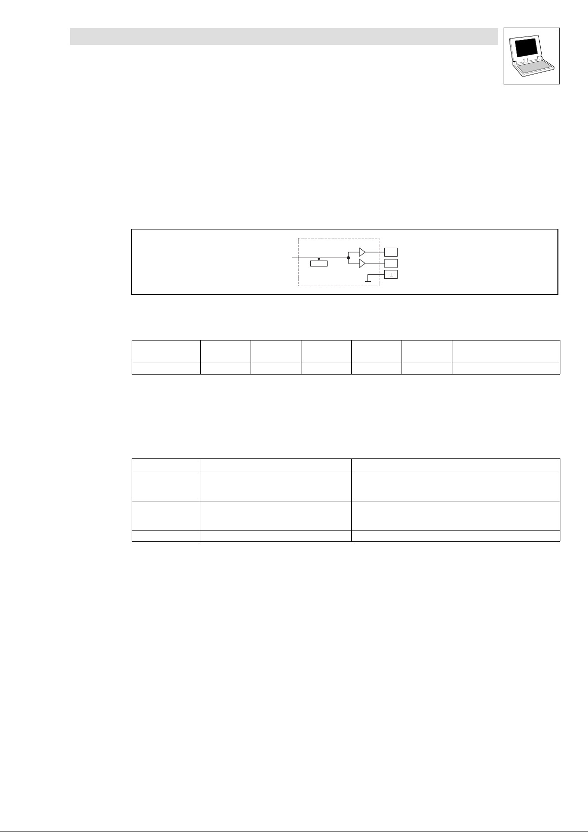
You can use this SB as a monitor output. You can output internal analog signals via
terminal AOV as voltage signals and
terminal AOI as current signals
and use them, e.g. as display or setpoint values for following drives.
Fig. 2−11 Outputs_ANALOG1
System variables
Variable Data type Signal type Address Display
AOUT1_nOut_a Integer analog %QW11.0 C0434 dec [%] Analog output 1
Function
A voltage of 10 V is output at terminal AOV, if the signal on AOUT1_nOut_a = 16384 = 100 %
A current of 20 mA is output at terminal AOI, if the signal on AOUT1_nOut_a = 16384 = 100 %
Terminal assignment
Terminal Use Data
AOV Analog output 1 (voltage signal) Level:
AOI Analog output 1 (current signal) Level:
A Internal ground, GND −
Outputs_ANALOG1
AOUT1_nOut_a
C0434
AOV
AOI
A
code
Resolution:
Normalisation:
Resolution:
Normalisation:
Display
format
−10 V ... +10 V (max. 2 mA)
10 bits + sign
10 V 16384 100 %
−20 mA ... +20 mA
10 bits + sign
20 mA 16384 100 %
Notes
L
DrivePLC DE 6.0
2−21
Page 36
Drive PLC
System blocks
2.7 ANALOG2_IO (node number 12)
2.7 ANALOG2_IO (node number 12)
2.7.1 Inputs_ANALOG2 (analog input)
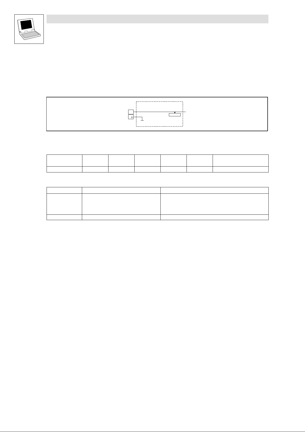
This SB forms the interface for analog signals via terminal AI2, A.
Fig. 2−12 Inputs_ANALOG2
System variables
Variable Data type Signal type Address Display
AIN2_nIn_a Integer analog %IW12.0 C0400/2 dec [%] Analog input 2
Terminal assignment
Terminal Use Data
AI2 Analog input 2 Level:
A Internal ground, GND −
Inputs_ANALOG2
AI2
A
AIN2_nIn_a
C0400/2
code
Resolution:
Internal resistance:
Normalisation:
Display
format
−10 V ... +10 V
10 bits + sign
100 k
10 V 16384 100 %
Notes
2−22
DrivePLC DE 6.0
L
Page 37
Drive PLC
System blocks
2.8 ANALOG3_IO (node number 13)
2.8 ANALOG3_IO (node number 13)
2.8.1 Inputs_ANALOG3 (analog input)
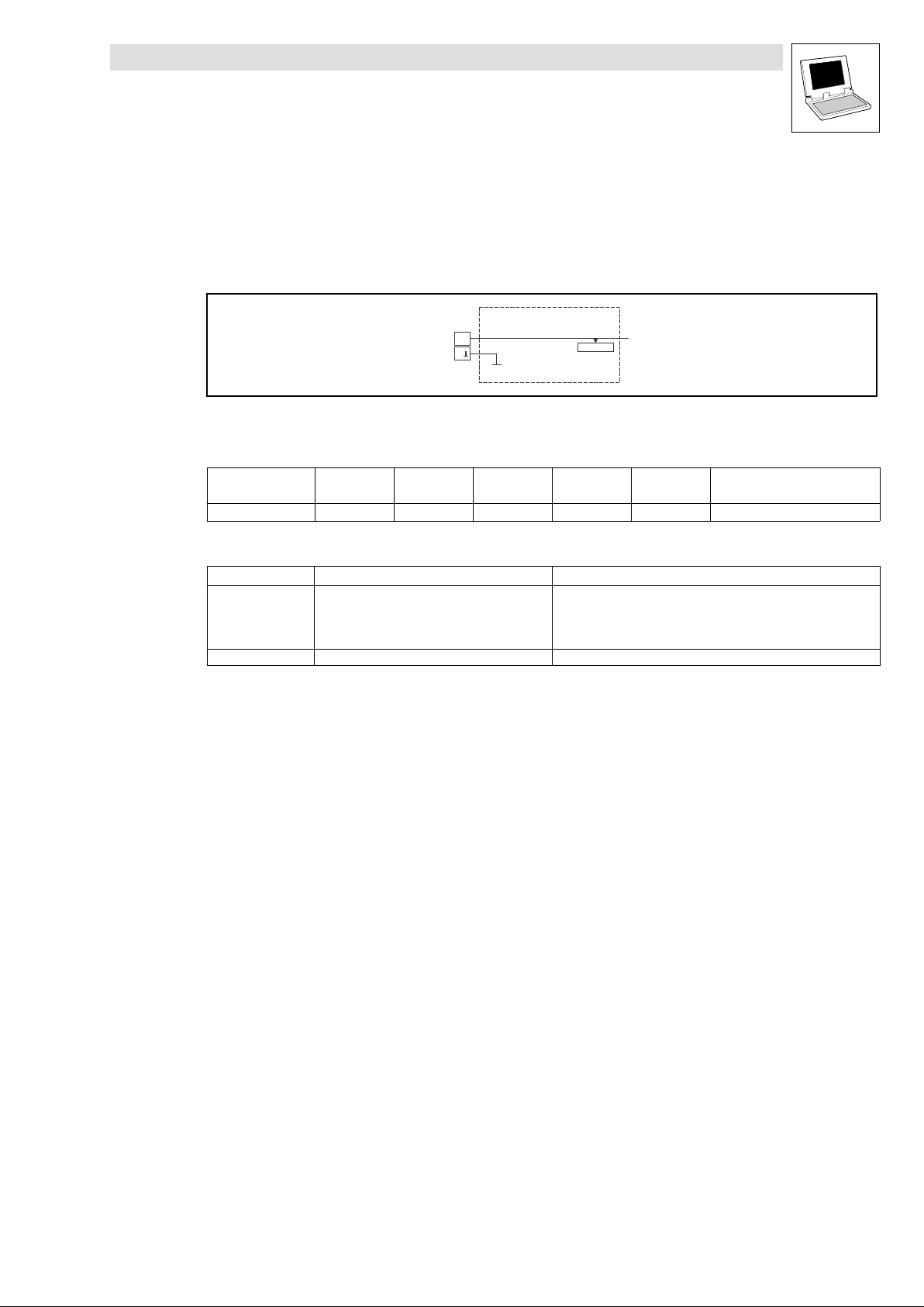
This SB forms the interface for analog signals via terminal AI3, A.
Fig. 2−13 Inputs_ANALOG3
System variables
Variable Data type Signal type Address Display
AIN3_nIn_a Integer analog %IW13.0 C0400/3 dec [%] Analog input 3
Terminal assignment
Terminal Use Data
AI3 Analog input 3 Level:
A Internal ground, GND −
Inputs_ANALOG3
AI3
A
AIN3_nIn_a
C0400/3
code
Resolution:
Internal resistance:
Normalisation:
Display
format
−10 V ... +10 V
10 bits + sign
100 k
10 V 16384 100 %
Notes
L
DrivePLC DE 6.0
2−23
Page 38
Drive PLC
System blocks
2.9 DIGITAL_IO (node number 1)
2.9 DIGITAL_IO (node number 1)
2.9.1 Inputs_DIGITAL (digital inputs)
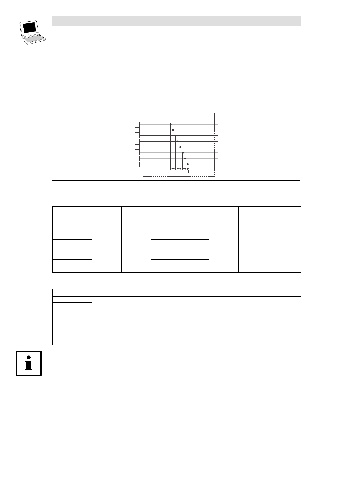
This SB reads the signals at terminals I1 ... I8 and conditions them.
I1
I2
I3
I4
I5
I6
I7
I8
Fig. 2−14 Inputs_DIGITAL
Inputs_DIGITAL
DIGIN_bIn1_b
DIGIN_bIn2_b
DIGIN_bIn3_b
DIGIN_bIn4_b
DIGIN_bIn5_b
DIGIN_bIn6_b
DIGIN_bIn7_b
DIGIN_bIn8_b
C0443
System variables
Variable Data type Signal type Address Display
DIGIN_bIn1_b
DIGIN_bIn2_b %IX1.0.1 C0443 − bit2
DIGIN_bIn3_b %IX1.0.2 C0443 − bit3
DIGIN_bIn4_b %IX1.0.3 C0443 − bit4
DIGIN_bIn5_b %IX1.0.4 C0443 − bit5
DIGIN_bIn6_b %IX1.0.5 C0443 − bit6
DIGIN_bIn7_b %IX1.0.6 C0443 − bit7
DIGIN_bIn8_b %IX1.0.7 C0443 − bit8
Bool binary
%IX1.0.0 C0443 − bit1
code
Display
format
bin Digital inputs I1 ... I8
Notes
Electrical data of the input terminals
Terminal Use Data
I1
I2
I3
I4
I5
I6
I7
I8
freely assignable
LOW level:
HIGH level:
Input current:
0 ... +4 V
+13 ... +30 V
8 mA per input (at 24 V)
Tip!
You can use I2 ... I4 as real interrupt inputs. The references to the hardware interrupt inputs are in the
task configuration. Response time of the interrupt task: < 250 s.
More detailed information about Drive PLC terminal strips/control connections can be found in the
corresponding Mounting Instructions!
2−24
DrivePLC DE 6.0
L
Page 39
Drive PLC
System blocks
2.9 DIGITAL_IO (node number 1)
2.9.2 Outputs_DIGITAL (digital outputs)
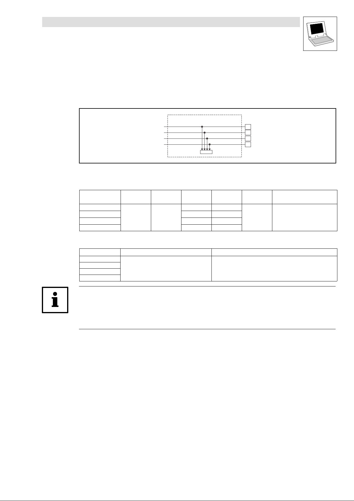
This SB conditions digital signals and outputs them at terminals O1 ... O4.
Fig. 2−15 Outputs_DIGITAL
System variables
Variable Data type Signal type Address Display
DIGOUT_bOut1_b
DIGOUT_bOut2_b %QX1.0.1 C0444 − Bit2
DIGOUT_bOut3_b %QX1.0.2 C0444 − Bit3
DIGOUT_bOut4_b %QX1.0.3 C0444 − Bit4
Electrical data of the output terminals
Terminal Use Data
O1
O2
O3
O4
Bool binary
freely assignable
DIGOUT_bOut1_b
DIGOUT_bOut2_b
DIGOUT_bOut3_b
DIGOUT_bOut4_b
%QX1.0.0 C0444 − Bit1
Outputs_DIGITAL
C0444
code
LOW level:
HIGH level:
Output current:
O1
O2
O3
O4
Display
format
bin Digital outputs O1 ... O4
0 ... +4 V
+13 ... +30 V
max. 1 A per output
Notes
Tip!
If the user program has not been started, all outputs are defined as "LOW" after switch−on.
More detailed information about Drive PLC terminal strips/control connections can be found in the
corresponding Mounting Instructions!
L
DrivePLC DE 6.0
2−25
Page 40
Drive PLC
System blocks
2.10 FCODE_FreeCode (node number 141)
2.10 FCODE_FreeCode (node number 141)
Free codes
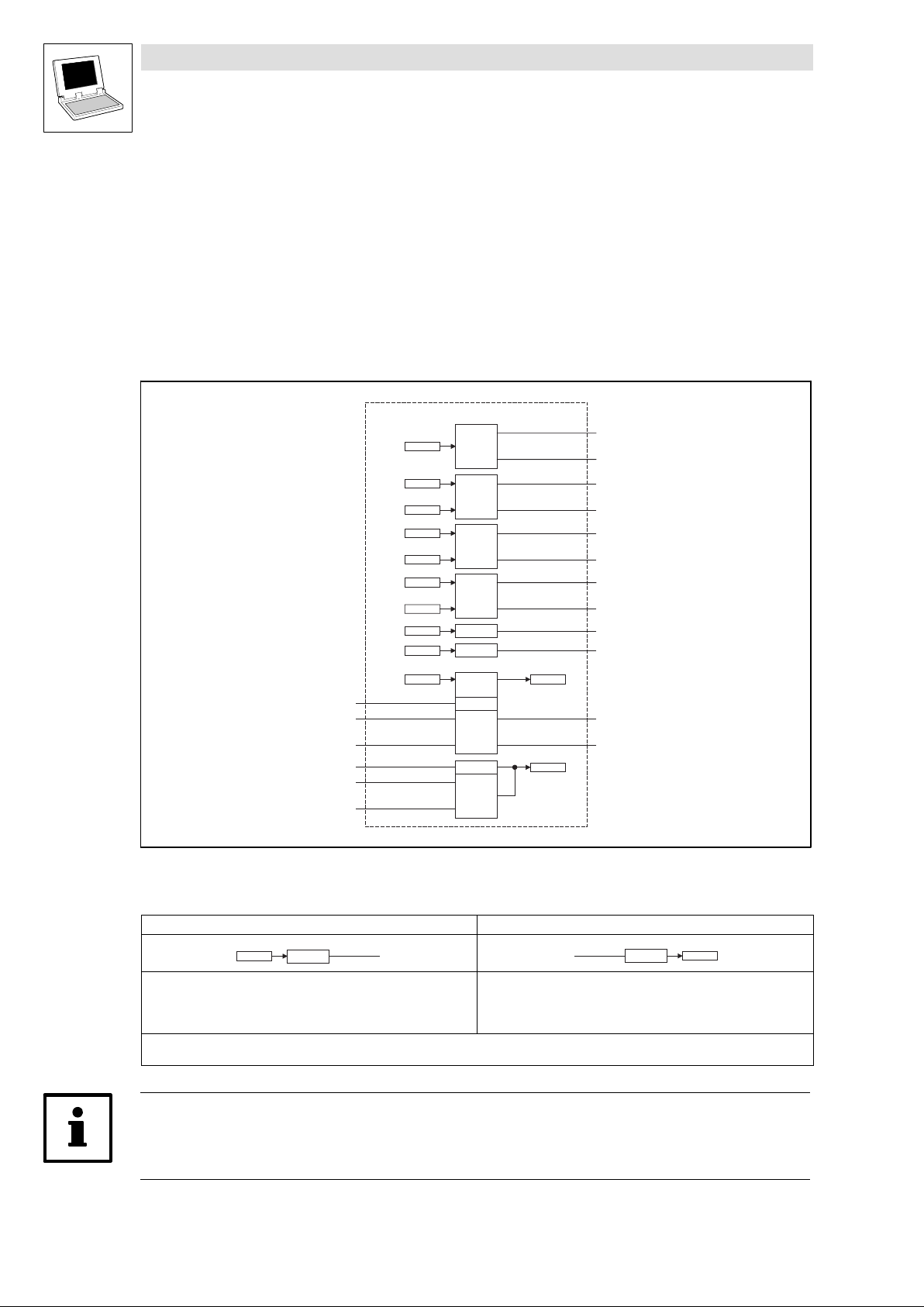
At Lenze, controller parameters are called codes. The PLC can be adapted to your application
without additional programming by changing codes.
This SB provides several variables which directly read "free" PLC codes and processes them further
in the PLC program or the codes can be written by the PLC program.
FCODE_FreeCodes
C0471
C0472/1
...
C0472/20
C0473/1
...
C0473/10
C0474/1
...
C0474/5
C0475/1
C0475/2
C0135
FCODE_wC135
FCODE_bC135Bit0_b
FCODE_bC135Bit15_b
FCODE_wC150
FCODE_bC150Bit0_b
FCODE_bC150Bit15_b
...
...
DWORD
TO
BIT/BOOL
% TO INT
INT
DINT
INT
INT
Input &
Output
WORD
16 Bit
WORD
16 Bit
FCODE_bC471Bit0_b
...
FCODE_bC471Bit31_b
FCODE_nC472_1_a
...
FCODE_nC472_20_a
FCODE_nC473_1_a
...
FCODE_nC473_10_a
FCODE_dnC474_1_p
...
FCODE_dnC474_5_p
FCODE_nC475_1_v
FCODE_nC475_2_v
C0135
FCODE_bC135Bit0_b
...
FCODE_bC135Bit15_b
C0150
Fig. 2−16 FCODE_FreeCodes
Code ð PLC program
The PLC codes listed in Fig. 2−16 in boxes on the left−hand side are
directly assigned to the variables listed on the right−hand side.
These variables can only be read by the PLC program.
See chapter 2.10.1, "Inputs_FCODE"
Codes are converted into variables (and vice versa) according to a fixed routine.
In the code table, you can find the options that can be set and the Lenze settings. ^ 8−16
Tip!
Code C0135 can be read and written via the variables FCODE_bC135Bit0_b ...
FCODE_bC135Bit15_b (input & output).
2−26
Cxxxx
FCODE_...
DrivePLC DE 6.0
PLC program ð Code
FCODE_...
Cxxxx
The variables listed in Fig. 2−16 on the left−hand side are assigned to
the codes listed in boxes on the right−hand side.
These codes can only be read from "outside".
See chapter 2.10.2, "Outputs_FCODE"
L
Page 41
Drive PLC
System blocks
2.10 FCODE_FreeCode (node number 141)
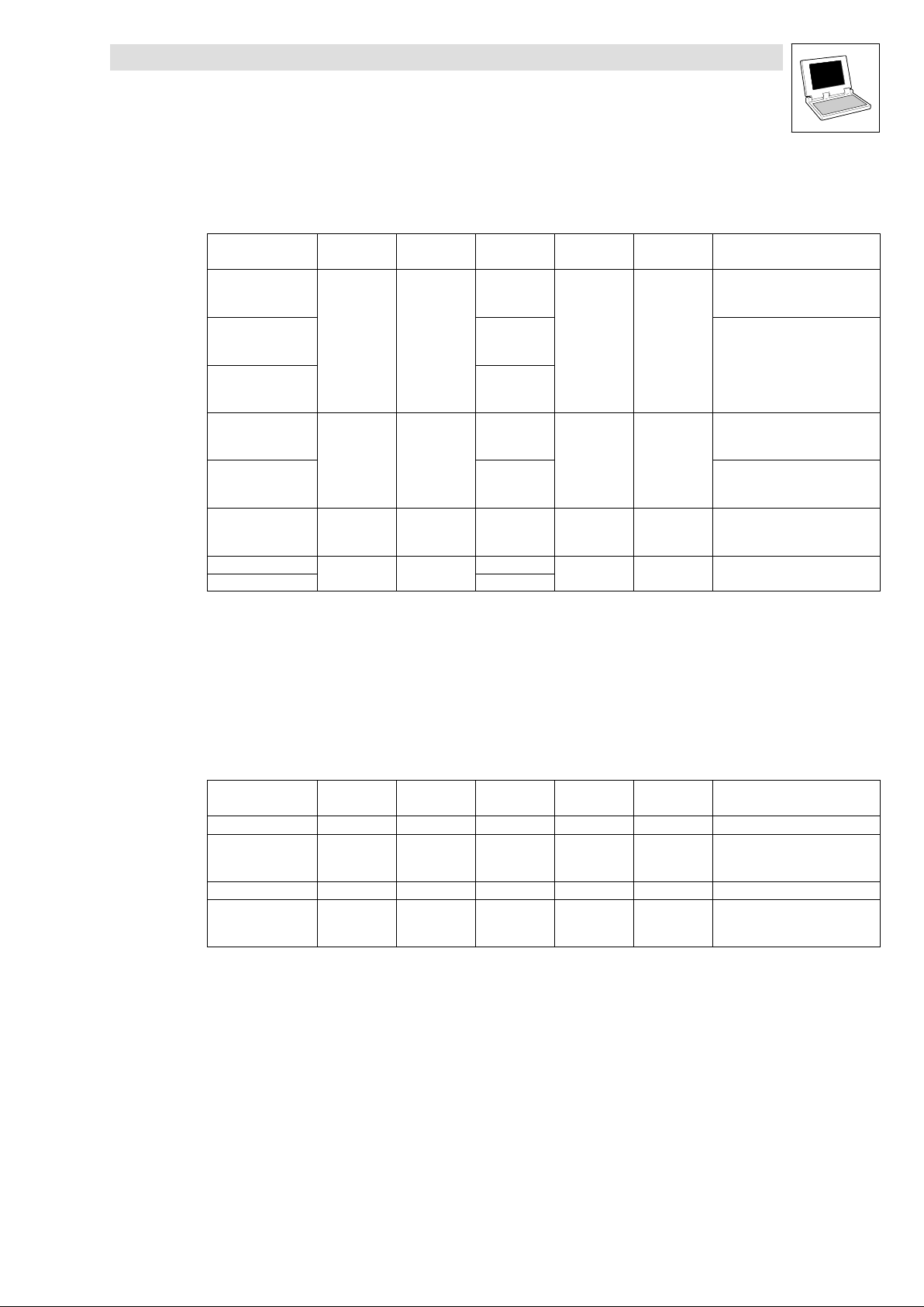
2.10.1 Inputs_FCODE
System variables
Variable Data type Signal type Address Display
FCODE_bC135Bit0_b
FCODE_bC135Bit15_b
FCODE_bC471Bit0_b
FCODE_bC471Bit15_b
FCODE_bC471Bit16_b
FCODE_bC471Bit31_b
FCODE_nC472_1_a
FCODE_nC472_20_a
FCODE_nC473_1_a
FCODE_nC473_10_a
FCODE_dnC474_1_p
FCODE_dnC474_5_p
FCODE_nC475_1_v
FCODE_nC475_2_v %IW141.43
...
...
...
...
...
...
Bool binary − −
Integer analog
Double integer position
Integer Velocity
%IX141.0.0
...
%IX141.0.15
%IX141.1.0
...
%IX141.1.15
%IW141.2
...
%IW141.21
%IW141.22
...
%IW141.31
%ID141.16
...
%ID141.20
%IW141.42
code
− −
− − default = 0
− − default = 0
Display
format
Notes
default = 0
Also output variables
(see table below)
default = 0
default = 0.00 %
default = 0
C0473/1,2 = 1
Example
It is possible to enter a percentage [%] under PLC code C0472/1 by using, for instance, the keypad.
This value is directly assigned to the variable FCODE_nC472_1_a (data type "Integer") and can be
processed further in the PLC program.
2.10.2 Outputs_FCODE
System variables
Variable Data type Signal type Address Display
FCODE_wC135 WORD − %QW141.0 − −
FCODE_bC135Bit0_b
...
FCODE_bC135Bit15_b
FCODE_wC150 WORD − %QW141.1 − −
FCODE_bC150Bit0_b
...
FCODE_bC150Bit15_b
Bool binary
Bool binary
%QX141.0.0
...
%QX141.0.15
%QX141.1.0
...
%QX141.1.15
code
− −
− −
Display
format
Notes
Also input variable
(see table above)
L
DrivePLC DE 6.0
2−27
Page 42
Drive PLC
System blocks
2.11 SYSTEM_FLAGS (system flags, node number 151)
2.11 SYSTEM_FLAGS (system flags, node number 151)
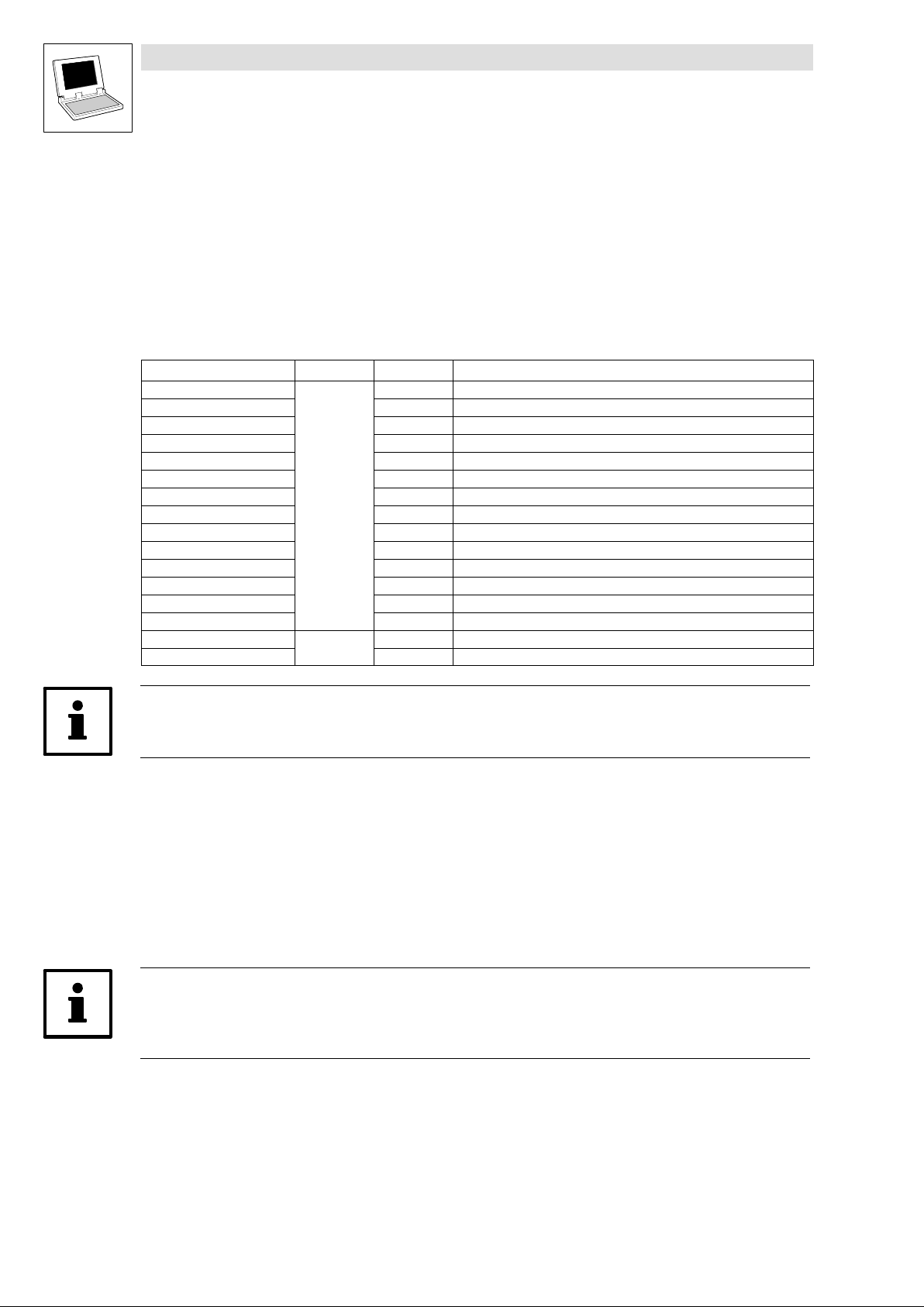
System flags are global variables which are permanently integrated into the run−time system. They
include functions that facilitate programming.
2.11.1 Inputs SYSTEM_FLAGS
The following system flags are included in the DrivePLC:
Variable Data type Address Notes
SYSTEM_bClock01Hz
SYSTEM_bClock1Hz %IX151.0.8 1.0 Hz system clock
SYSTEM_bClock10Hz %IX151.1.0 10 Hz system clock
SYSTEM_bClock0100Hz %IX151.1.8 100 Hz system clock
SYSTEM_bTogCycleTask %IX151.2.0 Toggle flag cyclic task
SYSTEM_b1LoopCyclicTask %IX151.2.8 First loop cyclic task
SYSTEM_b1LoopTask2 %IX151.3.0 First loop task ID2
SYSTEM_b1LoopTask3 %IX151.3.8 First loop task ID3
SYSTEM_b1LoopTask4 %IX151.4.0 First loop task ID4
SYSTEM_b1LoopTask5 %IX151.4.8 First loop task ID5
SYSTEM_b1LoopTask6 %IX151.5.0 First loop task ID6
SYSTEM_b1LoopTask7 %IX151.5.8 First loop task ID7
SYSTEM_b1LoopTask8 %IX151.6.0 First loop task ID8
SYSTEM_b1LoopTask9 %IX151.6.8 First loop task ID9
SYSTEM_nTaskInterval
SYSTEM_nTaskID %IW151.8 ID−number of current task
Bool
Integer
%IX151.0.0 0.1 Hz system clock
%IW151.7 Interval of current task
Tip!
The system variables are not generated in simulation mode.
SYSTEM_bClockxHz
These system flags output a fixed clock pulse with an equal pulse/pause ratio.
The flag is toggled in real time.
When you use this system flag, take care with the frequency used for polling the flag (aliasing
effect). You should use at least twice the toggle frequency.
Note!
The system flags SYSTEM_bClockxHz must not be used to trigger event−controlled tasks. Use
time−controlled tasks for this.
Example:
You would like to use the system flag SYSTEM_bClock100Hz as a clock for a counter.
The pulse/pause ratio is 5 ms/5 ms.
2−28
To avoid an aliasing effect, the counter must always be polled with an INTERVAL TASK < 5 ms.
DrivePLC DE 6.0
L
Page 43
Drive PLC
System blocks
2.11 SYSTEM_FLAGS (system flags, node number 151)
SYSTEM_bTogCycleTask
This system flag toggles with the cyclic task:
1. cycle: FALSE
2. cycle: TRUE
3. cycle: FALSE
4. cycle: TRUE
etc.
SYSTEM_nTaskInterval
This system flag indicates the interval of the running task with a resolution of 0.25 ms.
If, for instance, a 10−ms task is processed, the system flag indicates "40"
(40 x 0.25 ms = 10 ms).
If a task different from an interval task is processed, the system flag indicates "0".
SYSTEM_nTaskID
This system flag indicates the task ID of the running task.
SYSTEM_b1LoopCyclicTask/SYSTEM_b1Loop Task X
These system flags are TRUE only once during the first cycle of a task.
After the first cycle, the flags will be set to FALSE.
The only way to reset the status to TRUE is to reset the program in the PLC.
2.11.2 Outputs SYSTEM_FLAGS
Variable Data type Address Notes
SYSTEM_bPLCResetAndRun Bool %QX151.0.0 This system flag carries out a reset with an immediate restart of the Drive PLC:
After the reset, the flag is deleted and the restart carried out.
L
DrivePLC DE 6.0
2−29
Page 44
Drive PLC
System blocks
2.12 DCTRL_DriveControl (node number 121)
2.12 DCTRL_DriveControl (node number 121)
This system block is only implemented as of software version V 8.x.
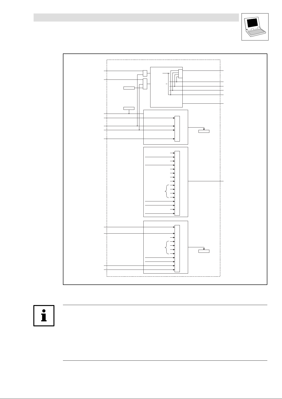
The system block DCTRL_DriveControl is used as interface between application and operating
system for device control:
TRIP−SET (^ 2−35))
TRIP−RESET (^ 2−35)).
In addition, the SB indicates the DrivePLC status for diagnostics purposes.
The process image is created in a fixed system task (interval: 2 ms).
Tip!
The inputs of the SB DCTRL_DriveControl only influence the internal device control.
If, for instance, a TRIP is activated by the operating system or the function block L_FWM() the
application program is not be stopped.
However, if a TRIP is activated as a result of a task overflow the application program of the PLC is
stopped as well!
2−30
DrivePLC DE 6.0
L
Page 45
Drive PLC
System blocks
2.12 DCTRL_DriveControl (node number 121)
DCTRL_DriveControl
DCTRL_bTripSet_b
DCTRL_bTripReset_b
C0043
FCODE_wC135
FCODE_bC135Bit0_b
FCODE_bC135Bit10_b
FCODE_bC135Bit11_b
FCODE_bC135Bit15_b
C0135
...
...
.10
or
TRIP SET
.11
or
TRIP RESET
...
...
or
0
...
10
11
...
15
DCTRL_bFail_b
DCTRL_bTrip_b
DCTRL_bWarn_b
DCTRL_bMeld _b
DCTRL_bExternalFault_b
DCTRL_wFaultNumber
C0135
FCODE_bC150Bit0_b
...
FCODE_bC150Bit6_b
FCODE_bC150Bit14_b
FCODE_bC150Bit15_b
DCTRL_bFail _b
DCTRL_bTrip _b
Gerätestatus
Device status
DCTRL_bWarn _b
DCTRL_bMeld _b
DCTRL_bExternalFault _b
...
PLC Stop
Gerätestatus
Device status
DCTRL_bWarn _b
DCTRL_bMeld _b
0
1
2
3
4
5
6
7
8
9
10
11
12
13
14
15
0
...
6
7
8
9
10
11
12
13
14
15
DCTRL_wStat
C0150
Fig. 2−17 System block "DCTRL_DriveControl" (The SB outputs are the inputs of the system control)
Tip!
The information PLC stop, device status, message and warning is written in a 2−ms system task
interval to bits 7 ... 13 of the variable FCODE_wC150 or of code C0150.
Therefore, only use C0150 as diagnostics code (reading) and do not write the system variable
FCODE_wC150, but only its bit−coded inputs FCODE_bC150Bit0_b, FCODE_bC150Bit6_b,
FCODE_bC150Bit14_b and FCODE_bC150Bit15_b.
Additional information can be found in the description of the system block FCOCD_FreeCode
(^ 2−26).
L
DrivePLC DE 6.0
2−31
Page 46
Drive PLC
System blocks
2.12 DCTRL_DriveControl (node number 121)
2.12.1 Inputs_DCTRL
System variables
Variable Data type Signal type Address
DCTRL_bFail_b Bool binary %IX121.0.0 − −
DCTRL_bTrip_b Bool binary %IX121.0.2 − −
DCTRL_bWarn_b Bool binary %IX121.0.12 − −
DCTRL_bMeld_b Bool binary %IX121.0.13 − −
DCTRL_bExternalFault
_b
DCTRL_wStat WORD − %IW121.0 − −
DCTRL_wFaultNumbe
r
Bool binary %IX121.0.15 − −
WORD − %IW121.2 − − Error number from C0168
Display
code
Display
format
Notes
Status word bit−coded
TRUE = Error active
Status word bit−coded
TRUE = Error active (TRIP or FQSP
active)
Status word bit−coded
TRUE = Warning active
Status word bit−coded
TRUE = Message active
Status word bit−coded
TRUE = External error
Status word with device status
(bit 8 ... 11, see below)
Tip!
Unlike ECS and SPLC, the binary signals of the SB DCTRL are on DCTRL_wStat!
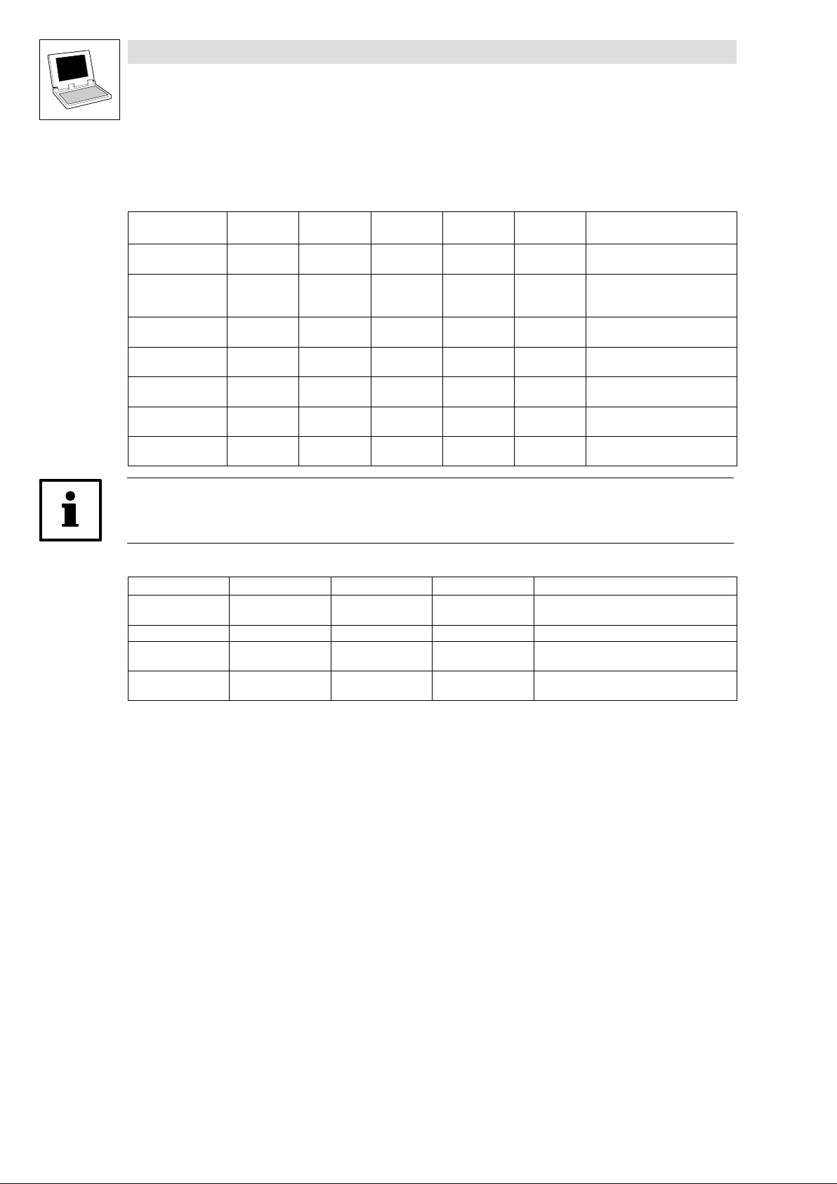
Device status: Bits 8 ...11 of DCTRL_wStat show the DrivePLC status binary coded:
DCTRL_wStat.11 DCTRL_wStat.10 DCTRL_wStat.9 DCTRL_wStat.8 Notes
0 0 0 0
0 1 1 0 Normal operation
0 1 1 1
1 0 0 0
Initialisation after connection of the supply
voltage
The activation of a monitoring function led to a
warning or message (FQSP)
The activation of a monitoring function led to a
TRIP
2−32
DrivePLC DE 6.0
L
Page 47
Drive PLC
System blocks
2.12 DCTRL_DriveControl (node number 121)
Codes
Code LCD
C0150 Status word 0
C0155 Status word 2 0
Possible settings
Lenze Selection
0 Not assigned
1 Not assigned
2 Not assigned
3 Not assigned
4 Not assigned
5 Not assigned
6 Not assigned
7 PLC stopped
8 Controller status 1
9 Controller status 2
10 Controller status 3
11 Controller status 4
12 Warning active
13 Message active
14 Not assigned
15 Not assigned
0 Fail
1 Not assigned
2 Not assigned
3 Not assigned
4 Not assigned
5 PLC stopped
6 TRIP / QSP
7 Not assigned
8 Not assigned
9 Not assigned
10 Not assigned
11 Not assigned
12 Not assigned
13 Not assigned
14 Not assigned
15 Not assigned
Info
Status word, access via code and
FCODE C0150
Free bits (0 ... 6, 14, 15) can be
written via FCODE_C0150.
Extended status word, read only
Tip!
The assignment of the status word bits marked as "not assigned" depends on the AIF module used
and the set transfer profile (e.g.: DRIVECOM).
L
DrivePLC DE 6.0
2−33
Page 48
Drive PLC
System blocks
2.12 DCTRL_DriveControl (node number 121)
2.12.2 Outputs_DCTRL
System variables
Variable Data type Signal type Address
DCTRL_bTripSet_b Bool binary %QX121.0.3 − − TRIP set
DCTRL_bTripReset_b Bool binary %QX121.0.4 − − Trip reset
Codes
Display
code
Display
format
Notes
Code LCD
C0043 Trip reset
C0135 Status word 2 0
1) Control bit of operating unit, no effect on Drive PLC
2) If C581 < 3 (message also possible)
3) Afterwards set to FALSE by operating system
Possible settings
Lenze Selection
0 Trip reset
1 Trip active
0 Not assigned
1 Not assigned
2 Not assigned
3 Run/stop
4 Not assigned
5 Not assigned
6 Not assigned
7 Not assigned
8 Not assigned
9 Not assigned
10 TRIP set
11 TRIP reset
12 Not assigned
13 Not assigned
14 Not assigned
15 Not assigned
Info
Active error TRIP reset
Status word, access via code and
FCODE_C0135
1)
2)
3)
Tip!
The assignment of the status word bits marked as "not assigned" depends on the AIF module used
and the set transfer profile (e.g.: DRIVECOM).
2−34
DrivePLC DE 6.0
L
Page 49
Drive PLC
System blocks
2.12 DCTRL_DriveControl (node number 121)
2.12.3 TRIP−SET
This function sets the control system to the Error status and indicates "External error" ("EEr")
Control word C0135 / FCODE_wC135 / FCODE_b135Bit10_b
Variable DCTRL_bTripSet_b
The response to a TRIP can be set under C0581:
Codes
Code LCD
C0581 MONIT EEr 0 or
Tip!
The inputs for external error activation are polled in a system task every 2 ms.
The "External error" ("EEr") function is available as of operating system version V8.0. When the
function is activated (C0581 < 3), please note that the "EEr" error is active when writing bit 10 = TRUE
of code C0135 or of FCODE_wC135.
2.12.4 TRIP−RESET
This function resets a current TRIP when the cause of the error has been removed.
Variable DCTRL_bTripReset_b
Control word C0135 / FCODE_wC135 / FCODE_b135Bit11_b
Code C0043
Possible settings
Lenze Selection
3 as
of
V8.0
0 TRIP
1 Message
2 Warning
3 Off
Info
Monitoring configuration:
"ExternalFault"(FWM EEr)
Tip!
The function is only executed through a FALSE−TRUE transition of the indicated signals. The
transition is polled in a system task every 2 ms.
2.12.5 TRIP status (DCTRL_bExternalFault_b)
If a TRIP is activated via the variable DCTRL_bTripSet_b or C0135/bit10, the variable
DCTRL_bExternalFault_b is set to TRUE. DCTRL_bExternalFault_b is reset to FALSE as soon as the
error source is reset.
L
DrivePLC DE 6.0
2−35
Page 50
Drive PLC
System blocks
2.13 PWRUP_PowerUpControl (node number 171)
2.13 PWRUP_PowerUpControl (node number 171)
This system block is only implemented as of software version V 8.1.
If the system block PWRUP_PowerUpControl is integrated into the control configuration, it can
avoid a U15 TRIP in the event of a short mains voltage dip.
const.
PWRUP_PowerUpControl
PWRUP_bWaitFor24V_b
PWRUP_wMaxDelayTimeFor24V_b
Fig. 2−18 PWRUP_PowerUpControl
0
1
24 V
PLC init
Fig. 2−19 Drive PLC behaviour in the event of a short dip of the 24−V−supply voltage
Tip!
This behaviour can only be activated if the control bit and the control word are contained in the
system POU "PLC_ColdStart".
If the system block is activated, a U15 error is indicated as warning in the history buffer
2−36
DrivePLC DE 6.0
L
Page 51
Drive PLC
System blocks
2.13 PWRUP_PowerUpControl (node number 171)
2.13.1 Outputs_PWRUP
System variables
Variable Data type Signal type Address
PWRUP_bWaitFor24V
_b
PWRUP_wMaxDelayTi
meFor24V
Bool binary %QX171.1.0 − −
WORD − %QW171.0 − −
Display
code
Display
format
Notes
TRUE: After initialisation, wait and
see if a sufficient supply voltage is
applied again (>17.5 V)
Maximum waiting time in ms; U15
TRIP is activated unless a supply
voltage of at least 17.5 V is
applied after this time.
L
DrivePLC DE 6.0
2−37
Page 52

Drive PLC
System blocks
2.13 PWRUP_PowerUpControl (node number 171)
2−38
DrivePLC DE 6.0
L
Page 53
3 Standard I/O FIF module
The Standard I/O FIF module extends the Drive PLC by the following inputs and outputs:
Signal type Number SB Node number Info
Inputs
Outputs
Tip!
Observe the installation kit for the Standard I/O FIF module!
analog 1 ANALOG_IO_FIF W Inputs_ANALOG_FIF (AIN1_FIFSTDIO) 201 ^ 3−2
digital 5 DIGITAL_IO_FIF W Inputs_DIGITAL_FIF (DIGIN_FIFSTDIO) 200 ^ 3−4
analog 1 ANALOG_IO_FIF W Outputs_ANALOG_FIF (AOUT1_FIFSTDIO) 201 ^ 3−3
digital 1 DIGITAL_IO_FIF W Outputs_DIGITAL_FIF (DIGOUT_FIFSTDIO) 200 ^ 3−5
Drive PLC
System blocks − FIF Standard−I/O
L
DrivePLC DE 6.0
3−1
Page 54
Drive PLC
System blocks − FIF Standard−I/O
3.1 ANALOG_IO_FIF (node number 201)
3.1 ANALOG_IO_FIF (node number 201)
3.1.1 Inputs_ANALOG_FIF (analog input, "Standard I/O" FIF module)
This SB forms the interface for analog signals via terminal 8 of the Standard I/O FIF module as
setpoint input or actual value input.
Inputs_ANALOG_FIF
8
7
Fig. 3−1 Inputs_ANALOG_FIF
System variables
A
AIN1_nIn_FIFSTDIO_a
D
C0481
Variable Data type Signal type Address Display
code
AIN1_nIn_FIFSTDIO_a Integer analog %IW201.0 C0481 dec [%] Analog input 1
Display
format
Notes
Standard I/O
Input signal setting
By suitable switch settings at the Standard I/O FIF module the following input signals can be
processed:
Input range1) for terminal 8
1 2 3 4 5
0 ... +5 V OFF OFF ON OFF OFF
0 ... +10 V (Lenze setting) OFF OFF ON OFF ON
−10 ... +10 V ON ON OFF OFF OFF
0 ... +20 mA OFF OFF ON ON OFF
1)
The selected input range is adjusted to the integer range (0 ... 16384) of the variable AIN1_nIn_FIFSTDIO_a.
Example: selected input range = 0 ... +10 V
Input signal (terminal 8) 0 V + 5 V + 10 V
AIN1_nIn_FIFSTDIO_a 0 8192 16384
Switch setting
Electrical data of the input terminals:
Terminal Use level Data
8 Analog input 1 0 ... +5 V
7 GND1, reference potential
for analog signals
0 ... +10 V
−10 ... +10 V
0 ... +20 mA
− −
Resolution:
Linearity error:
Temperature error:
Input resistance:
10 bit
0.5 %
0.3 % (0 ... 60 °C)
> 50 k (voltage signal)
250 (current signal)
3−2
Tip!
Detailed information about the terminal assignment for the Standard I/O FIF module can be found
in the corresponding Mounting Instructions!
DrivePLC DE 6.0
L
Page 55
Drive PLC
System blocks − FIF Standard−I/O
3.1 ANALOG_IO_FIF (node number 201)
3.1.2 Outputs_ANALOG_FIF (analog output, "Standard I/O" FIF module)
This SB can be used as a monitor output. Internal signals can be given out as voltage signals via
terminal 62 of the Standard I/O FIF module and used, e.g. as display or setpoint values for following
drives.
Outputs_ANALOG_FIF
AOUT1_nOut_FIFSTDIO_a
C0484
Fig. 3−2 Outputs_ANALOG_FIF
System variables
62
7
Variable Data type Signal type Address Display
code
AOUT1_nOut_FIFSTDIO_a Integer analog %QW201.0 C0484 dec [%] Analog output 1
Display
format
Notes
Standard I/O
Function
A voltage of 10 V is given out at terminal 62 of the Standard I/O FIF module if the signal at
AOUT1_nOut_FIFSTDIO_a = 16384 = 100 %.
Electrical data of the output terminals:
Terminal Use level Data
62 Analog output 1 0 ... +10 V Resolution:
7 GND1, reference potential
for analog signals
− −
Linearity error:
Temperature error:
Load capacity:
10 bit
0.5 %
0.3 % (0 ... 60 °C)
max. 2 mA
Tip!
Detailed information about the terminal assignment for the Standard I/O FIF module can be found
in the corresponding Mounting Instructions!
L
DrivePLC DE 6.0
3−3
Page 56
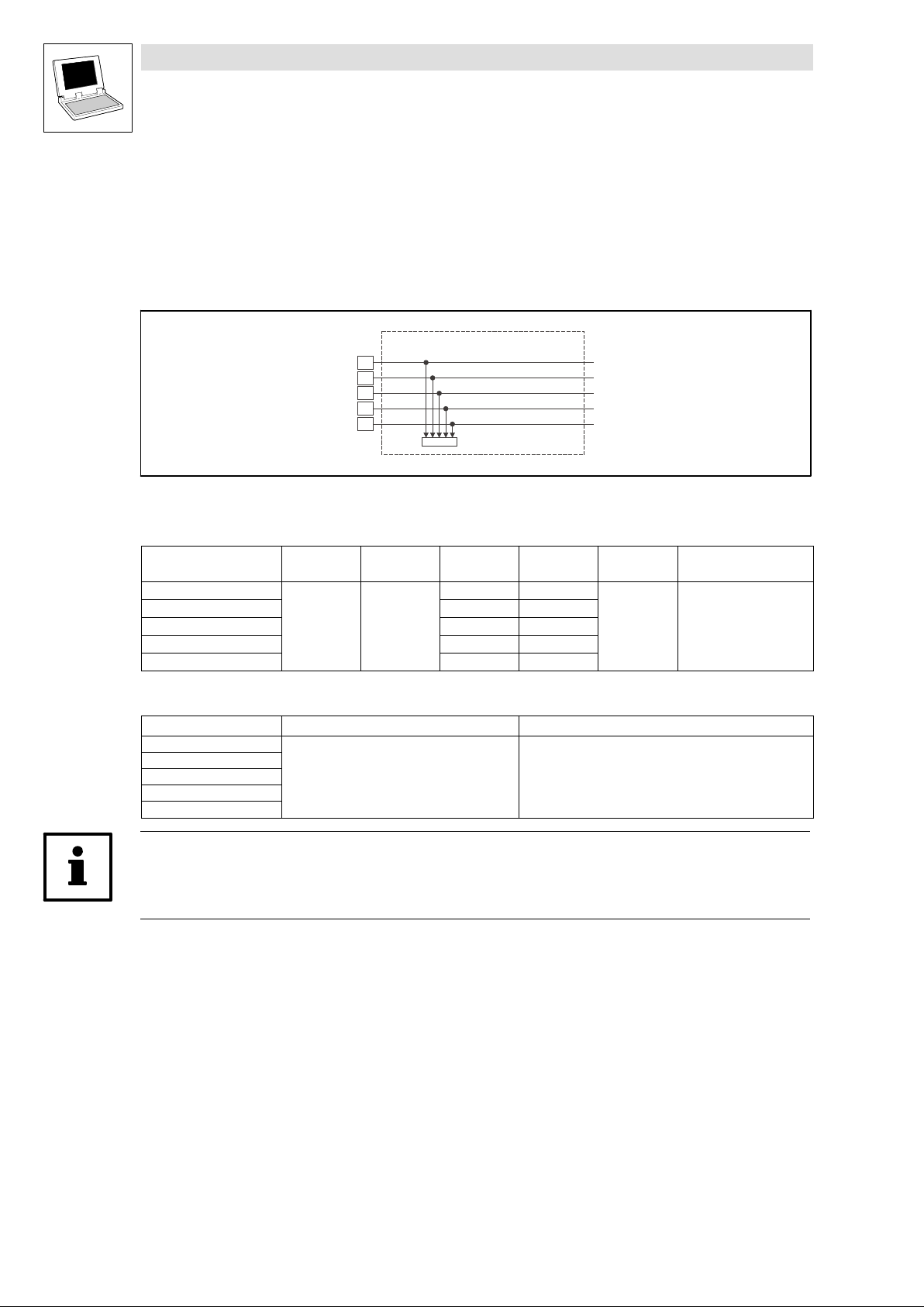
Drive PLC
System blocks − FIF Standard−I/O
3.2 DIGITAL_IO_FIF (node number 200)
3.2 DIGITAL_IO_FIF (node number 200)
3.2.1 Inputs_DIGITAL_FIF (digital inputs, "Standard I/O" FIF module)
This SB reads the signals at terminals E1 ... E4, 28 of the Standard I/O FIF module and conditions
them.
Inputs_DIGITAL_FIF
E1
E2
E3
E4
28
C0477
Fig. 3−3 Inputs_DIGITAL_FIF
DIGIN_bIn1_FIFSTDIO_b
DIGIN_bIn2_FIFSTDIO_b
DIGIN_bIn3_FIFSTDIO_b
DIGIN_bIn4_FIFSTDIO_b
DIGIN_bIn28_FIFSTDIO_b
System variables
Variable Data type Signal type Address Display
DIGIN_bIn28_FIFSTDIO_b
DIGIN_bIn1_FIFSTDIO_b %IX200.0.1 C0477 − bit3
DIGIN_bIn2_FIFSTDIO_b %IX200.0.2 C0477 − bit4
DIGIN_bIn3_FIFSTDIO_b %IX200.0.3 C0477 − bit5
DIGIN_bIn4_FIFSTDIO_b %IX200.0.4 C0477 − bit1
Bool binary
%IX200.0.0 C0477 − bit2
code
Display
format
bin
Notes
Electrical data of the input terminals:
Terminal Use Data
E1
E2
E3
E4
28
freely assignable
LOW level:
HIGH level:
Input resistance:
0 ... +3 V
+12 ... +30 V
(PLC level, HTL)
3.3 k
Tip!
Detailed information about the terminal assignment for the Standard I/O FIF module can be found
in the corresponding Mounting Instructions!
3−4
DrivePLC DE 6.0
L
Page 57
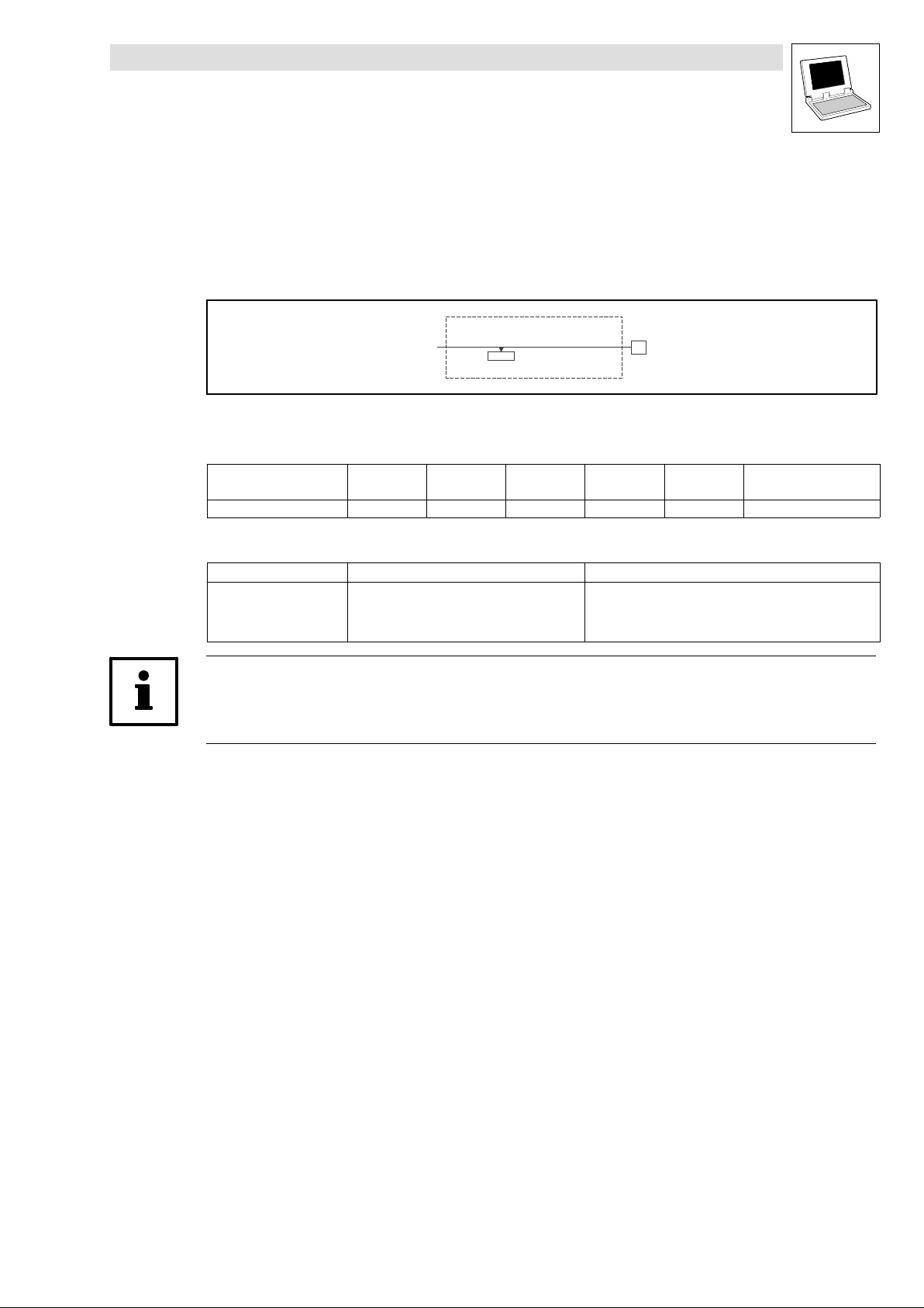
Drive PLC
System blocks − FIF Standard−I/O
3.2 DIGITAL_IO_FIF (node number 200)
3.2.2 Outputs_DIGITAL_FIF (digital outputs, "Standard I/O" FIF module)
This SB conditions a digital signal and transmits it to terminal A1 of the
Standard I/O FIF module.
Fig. 3−4 Outputs_DIGITAL_FIF
System variables
Variable Data type Signal type Address Display
DIGOUT_bOut1_FIFSTDIO_b Bool binary %QX200.0.0 C0479 − bit1 bin
Electrical data of the output terminal
Terminal Use Data
A1
Tip!
Detailed information about the terminal assignment for the Standard I/O FIF module can be found
in the corresponding Mounting Instructions!
DIGOUT_bOut1_FIFSTDIO_b
C0479
freely assignable
Outputs_DIGITAL_FIF
Output voltage:
Output current:
code
A1
Display
format
0/+20 V with DC internal
0/+24 V with DC external
10 mA with DC internal
50 mA with DC external
Notes
L
DrivePLC DE 6.0
3−5
Page 58

Drive PLC
System blocks − FIF Standard−I/O
3.2 DIGITAL_IO_FIF (node number 200)
3−6
DrivePLC DE 6.0
L
Page 59
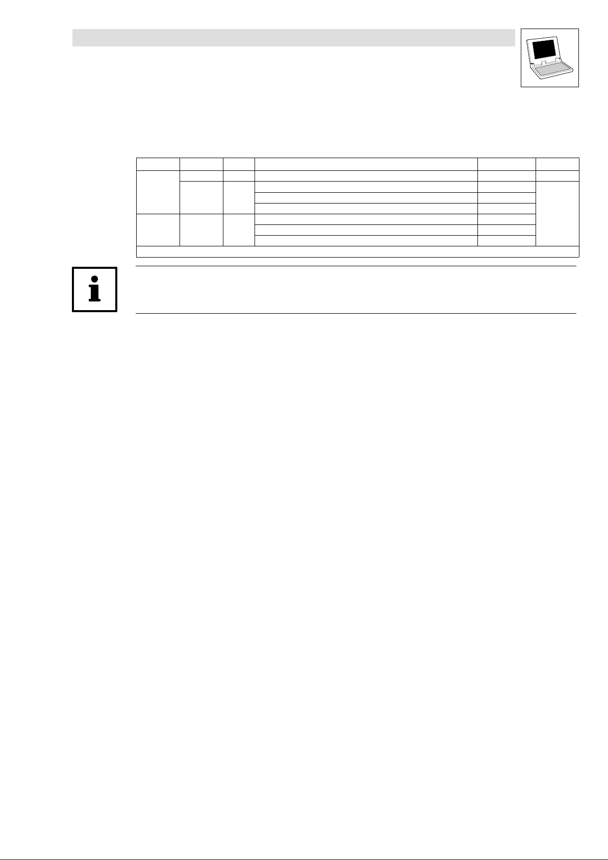
4 CAN−I/O FIF module
The CAN−I/O FIF module extends the Drive PLC by the following inputs and outputs:
Signal type Number SB Node number Info
Inputs
Outputs System bus
* See "System bus (CAN) for Lenze PLCs" Manual
Tip!
Observe the installation kit for the CAN−I/O FIF module!
Digital 1 FIF_CAN_DIGITAL_IN W FIF_CAN_Inputs_DIGITAL
System bus
(CAN)
(CAN)
FIF_CAN1_IO W FIF_Inputs_CAN1 (FIF−CAN1_IN)
FIF_CAN2_IO W FIF_Inputs_CAN2 (FIF−CAN2_IN)
FIF_CAN3_IO W FIF_Inputs_CAN3 (FIF−CAN3_IN)
FIF_CAN1_IO W FIF_Outputs_CAN1 (FIF−CAN1_OUT)
FIF_CAN2_IO W FIF_Outputs_CAN2 (FIF−CAN2_OUT)
FIF_CAN3_IO W FIF_Outputs_CAN3 (FIF−CAN3_OUT)
Drive PLC
System blocks − FIF CAN−I/O
202
34
35
36
34
35
36
^ 4−2
*
L
DrivePLC DE 6.0
4−1
Page 60
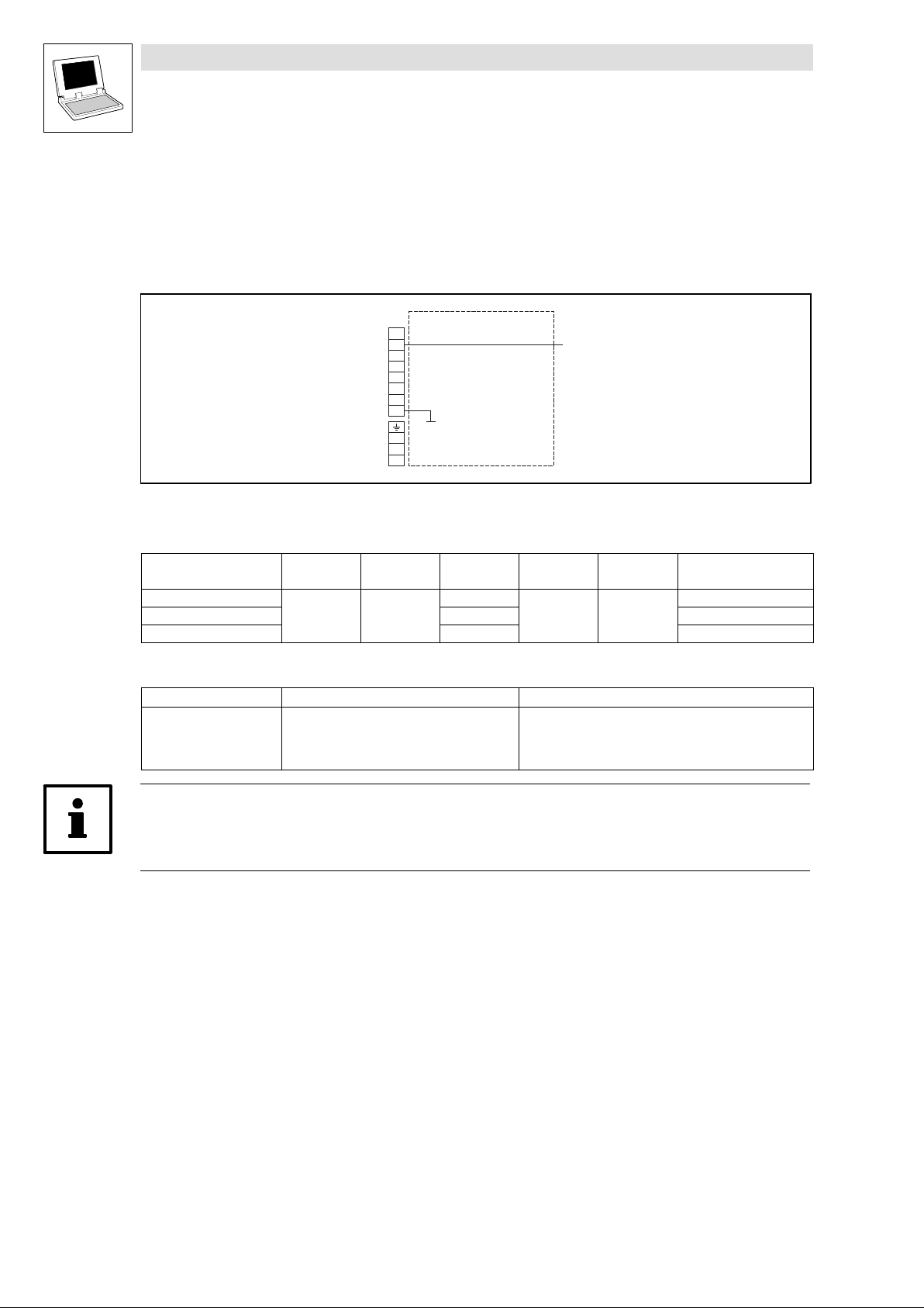
Drive PLC
System blocks − FIF CAN−I/O
4.1 FIF_CAN_DIGITAL_IN (node number 202)
4.1 FIF_CAN_DIGITAL_IN (node number 202)
4.1.1 FIF_CAN_Inputs_DIGITAL (digital input, "CAN−I/O" FIF module)
This SB reads the signal at terminal 28 of the CAN−I/O FIF module and conditions it.
FIF_CAN_DIGITAL_IN
X3
Fig. 4−1 FIF_CAN_DIGITAL_IN
20
28
20
E1
20
E2
59
7
7
LO
HI
DIGIN_bIn28_FIFCANIO_b
System variables
Variable Data type Signal type Address Display
DIGIN_bIn28_FIFCANIO_b
DIGIN_bIn1_FIFCANIO_b %IX202.0.1 E1
DIGIN_bIn2_FIFCANIO_b %IX202.0.2 E2
Bool binary
%IX202.0.0
code
− −
Display
format
Notes
Electrical data of the input terminal
Terminal Use Data
28 freely assignable LOW level:
HIGH level:
Input resistance:
0 ... +3 V
+12 ... +30 V
(PLC level, HTL)
3.3 k
Tip!
Detailed information about the terminal assignment for the CAN−I/O FIF module can be found in the
corresponding Mounting Instructions!
4−2
DrivePLC DE 6.0
L
Page 61
5 Extension board 1
The internal extension board 1 extends the Drive PLC by the following inputs and outputs:
Signal type Number SB Node number Info
Inputs Digital 6 DIGITAL_IO_EB1 W Inputs_DIGITAL_EB1 (DIGIN_EB1)
Outputs Digital 6 DIGITAL_IO_EB1 W Outputs_DIGITAL_EB1 (DIGOUT_EB1) ^ 5−3
Drive PLC
System blocks − Extension Board 1
X2
X1
2
^ 5−2
X3
Terminal Assignment
X1 GND, reference potential
X2 DC supply voltage (switched via X1/+O24 at the Drive PLC)
X3 Digital outputs O5 ... O10
X4 Digital inputs I9 ... I14
X4
L
DrivePLC DE 6.0
5−1
Page 62
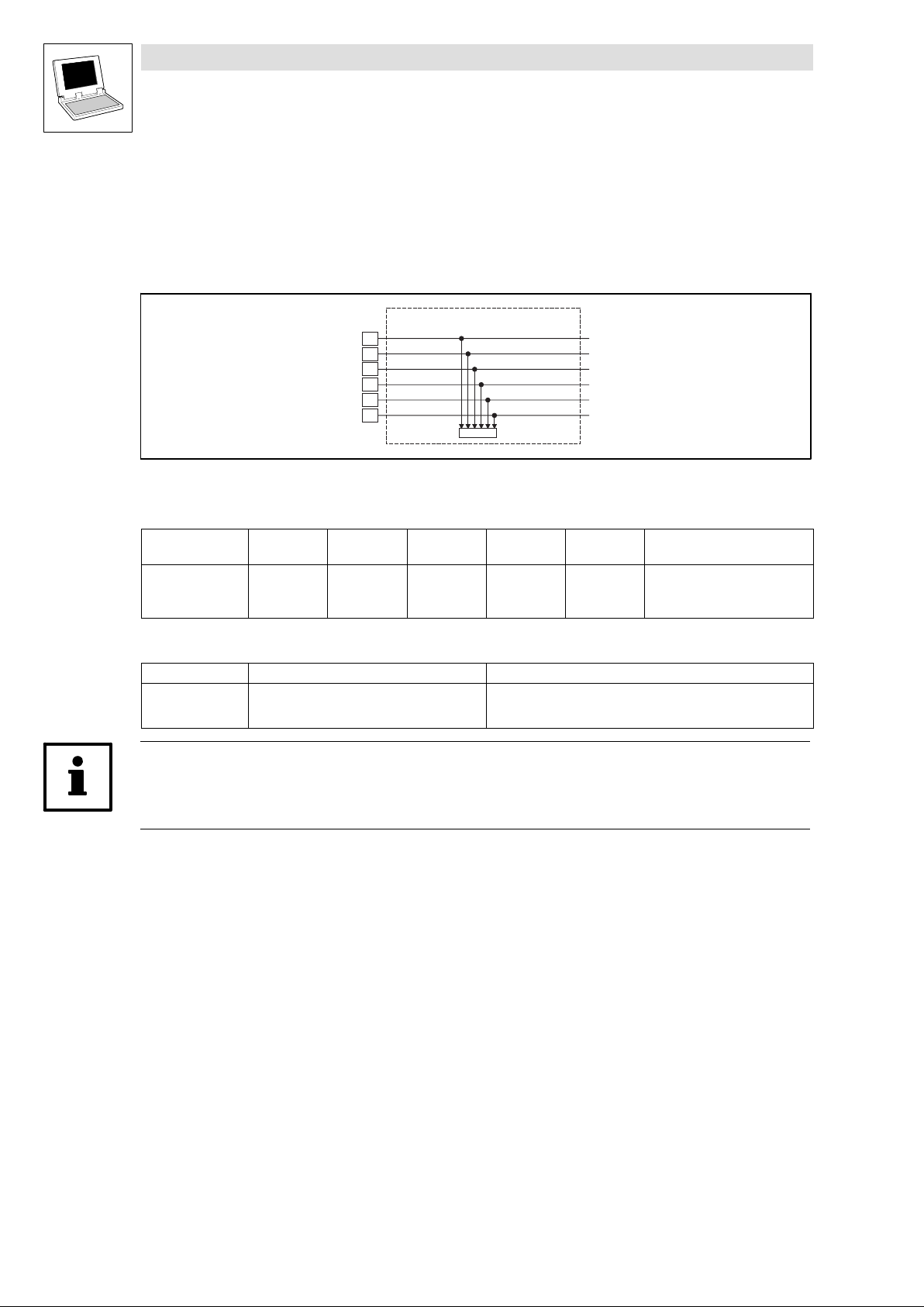
Drive PLC
System blocks − Extension Board 1
5.1 DIGITAL_IO_EB1 (node number 2)
5.1 DIGITAL_IO_EB1 (node number 2)
5.1.1 Inputs_DIGITAL_EB1 (digital inputs, extension board 1)
This SB reads the signals at terminals I9 ... I14 of the extension board 1 and conditions them.
Fig. 5−1 Inputs_DIGITAL_EB1
System variables
Variable Data type Signal type Address Display
DIGIN_bIn9_b
... ... ...
DIGIN_bIn14_b %IX2.0.5 C0446/1−bit6
Electrical data of the input terminals
Terminal Use Data
I9
...
I14
I9
I10
I11
I12
I13
I14
Bool binary
freely assignable
Inputs_DIGITAL_EB1
DIGIN_bIn9_b
DIGIN_bIn10_b
DIGIN_bIn11_b
DIGIN_bIn12_b
DIGIN_bIn13_b
DIGIN_bIn14_b
C0446/1
code
%IX2.0.0 C0446/1−bit1
LOW level:
HIGH level:
Input current:
Display
format
bin
0 ... +4 V
+13 ... +30 V
8 mA per input (at 24 V)
Notes
Tip!
Detailed information about the terminal assignment for the extension board 1 can be found in the
corresponding Mounting Instructions!
5−2
DrivePLC DE 6.0
L
Page 63
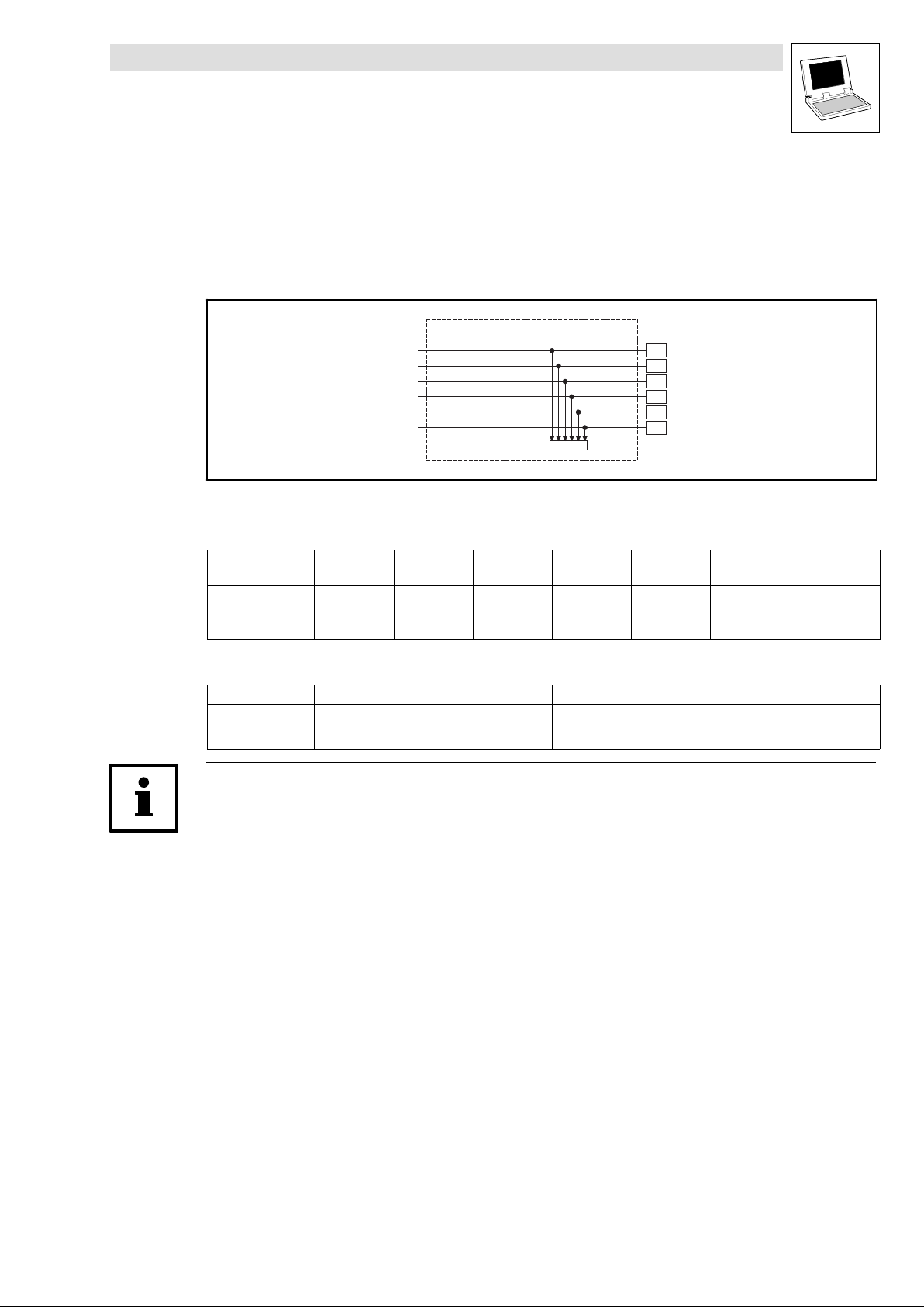
Drive PLC
System blocks − Extension Board 1
5.1 DIGITAL_IO_EB1 (node number 2)
5.1.2 Outputs_DIGITAL_EB1 (digital outputs, extension board 1)
This SB conditions the digital signals and outputs them at terminals O5 ... O10 of the extension
board 1.
Fig. 5−2 Outputs_DIGITAL_EB1
System variables
Variable Data type Signal type Address Display
DIGOUT_bOut5_b
... ... ...
DIGOUT_bOut10_b %QX2.0.5 C0448 − bit6
Electrical data of the output terminals
Terminal Use Data
O5
...
O10
DIGOUT_bOut5_b
DIGOUT_bOut6_b
DIGOUT_bOut7_b
DIGOUT_bOut8_b
DIGOUT_bOut9_b
DIGOUT_bOut10_b
Bool binary
freely assignable
Outputs_DIGITAL_EB1
C0448
code
%QX2.0.0 C0448 − bit1
LOW level:
HIGH level:
Output current:
O5
O6
O7
O8
O9
O10
Display
format
bin
0 ... +4 V
+13 ... +30 V
max. 1 A per output
Notes
Tip!
Detailed information about the terminal assignment for the extension board 1 can be found in the
corresponding Mounting Instructions!
L
DrivePLC DE 6.0
5−3
Page 64

Drive PLC
System blocks − Extension Board 1
5.1 DIGITAL_IO_EB1 (node number 2)
5−4
DrivePLC DE 6.0
L
Page 65
6 Extension board 2
The internal extension board 2 extends the Drive PLC by the following inputs and outputs:
Signal type Number SB Node number Info
Inputs Digital 14 DIGITAL_IO_EB2 W Inputs_DIGITAL_EB2 (DIGIN_EB2)
Outputs Digital 8 DIGITAL_IO_EB2 W Outputs_DIGITAL_EB2 (DIGOUT_EB2) ^ 6−3
Drive PLC
System blocks − Extension Board 2
X2
X1
3
^ 6−2
Terminal Assignment
X1 Digital outputs O5 ... 010
X2
X3 Digital inputs I15 ... I20
X4 Digital inputs I9 ... I14
Digital inputs I21, I22
Digital outputs O11, O12
GND, reference potential
DC supply voltage (switched via X1/+O24 at the Drive PLC)
X3
X4
L
DrivePLC DE 6.0
6−1
Page 66
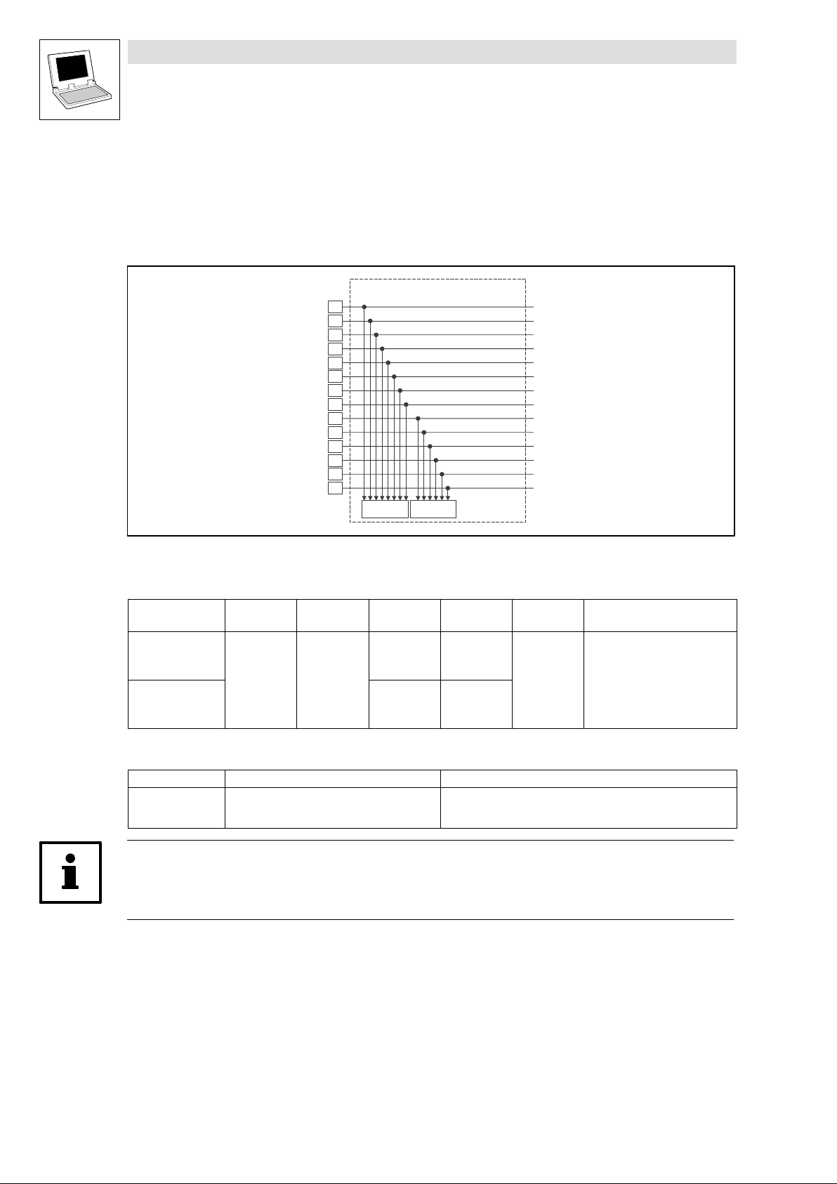
Drive PLC
System blocks − Extension Board 2
6.1 DIGITAL_IO_EB2 (node number 3)
6.1 DIGITAL_IO_EB2 (node number 3)
6.1.1 Inputs_DIGITAL_EB2 (digital inputs, extension board 2)
This SB reads the signals at terminals I9 ... I22 of the extension board 2 and conditions them.
Fig. 6−1 Inputs_DIGITAL_EB2
System variables
Variable Data type Signal type Address Display
DIGIN_bIn9_b
... ... ...
DIGIN_bIn16_b %IX3.0.7 C0446/1−bit8
DIGIN_bIn17_b %IX3.0.8 C0446/2−bit1
... ... ...
DIGIN_bIn22_b %IX3.0.13 C0446/2−bit6
I9
I10
I11
I12
I13
I14
I15
I16
I17
I18
I19
I20
I21
I22
Bool binary
Inputs_DIGITAL_EB2
C0446/1
Bit 1 … Bit 8
C0446/2
Bit 1 … Bit 6
%IX3.0.0 C0446/1−bit1
DIGIN_bIn9_b
DIGIN_bIn10_b
DIGIN_bIn11_b
DIGIN_bIn12_b
DIGIN_bIn13_b
DIGIN_bIn14_b
DIGIN_bIn15_b
DIGIN_bIn16_b
DIGIN_bIn17_b
DIGIN_bIn18_b
DIGIN_bIn19_b
DIGIN_bIn20_b
DIGIN_bIn21_b
DIGIN_bIn22_b
code
Display
format
bin
Notes
6−2
Electrical data of the input terminals
Terminal Use Data
I22
I9
...
freely assignable
LOW level:
HIGH level:
Input current:
0 ... +4 V
+13 ... +30 V
8 mA per input (at 24 V)
Tip!
Detailed information about the terminal assignment for the extension board 2 can be found in the
corresponding Mounting Instructions!
DrivePLC DE 6.0
L
Page 67
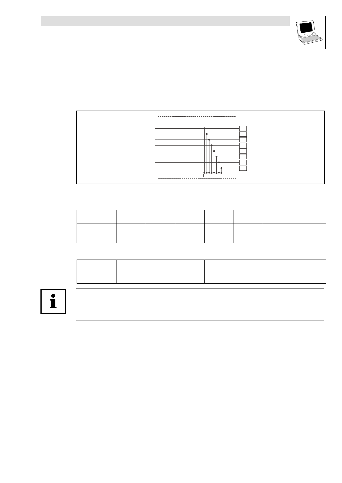
Drive PLC
System blocks − Extension Board 2
6.1 DIGITAL_IO_EB2 (node number 3)
6.1.2 Outputs_DIGITAL_EB2 (digital outputs, extension board 2)
This SB conditions the digital signals and outputs them at terminals O5 ... O12 of the extension
board 2.
Fig. 6−2 Outputs_DIGITAL_EB2
System variables
Variable Data type Signal type Address Display
DIGOUT_bOut5_b
... ... ...
DIGOUT_bOut12_b %QX3.0.7 C0448 − bit8
Electrical data of the output terminals
Terminal Use Data
O5
...
O12
DIGOUT_bOut5_b
DIGOUT_bOut6_b
DIGOUT_bOut7_b
DIGOUT_bOut8_b
DIGOUT_bOut9_b
DIGOUT_bOut10_b
DIGOUT_bOut11_b
DIGOUT_bOut12_b
Bool binary
freely assignable
Outputs_DIGITAL_EB2
C0448
code
%QX3.0.0 C0448 − bit1
LOW level:
HIGH level:
Output current:
O5
O6
O7
O8
O9
O10
O11
O12
Display
format
bin
0 ... +4 V
+13 ... +30 V
max. 1 A per output
Notes
Tip!
Detailed information about the terminal assignment for the extension board 2 can be found in the
corresponding Mounting Instructions!
L
DrivePLC DE 6.0
6−3
Page 68

Drive PLC
System blocks − Extension Board 2
6.1 DIGITAL_IO_EB2 (node number 3)
6−4
DrivePLC DE 6.0
L
Page 69
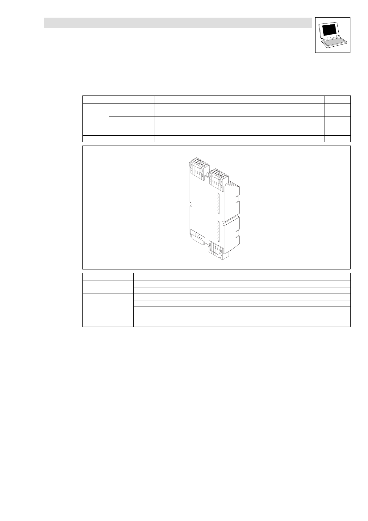
7 Extension board 3
The internal extension board 3 extends the Drive PLC by the following inputs and outputs:
Signal type Number SB Node number Info
Inputs Analog 2
Digital 8 DIGITAL_IO_EB3 W Inputs_DIGITAL_EB3 (DIGIN_EB3) 4 ^ 7−10
Encoder 1 DFIN_IO_
Outputs Digital 4 DIGITAL_IO_EB3 W Outputs_DIGITAL_EB3 (DIGOUT_EB3) 4 ^ 7−11
ANALOG4_IO_EB3 W Inputs_ANALOG4 (AIN4) 14 ^ 7−2
ANALOG5_IO_EB3 W Inputs_ANALOG5 (AIN5) 15 ^ 7−3
DigitalFrequency
Drive PLC
System blocks − Extension Board 3
W Inputs_DFIN (DF_IN) 21 ^ 7−4
X2
X1
Terminal Assignment
X1
X2
X3 Incremental encoder/counter input (Sub−D connector, 9−pole)
X4 Digital inputs I9 ... I14
Digital inputs I15, I16
Digital outputs O5 ... O8
Analog inputs AI4, AI5
GND, reference potential
DC supply voltage (switched via X1/+O24 at the Drive PLC)
X3
X4
L
DrivePLC DE 6.0
7−1
Page 70
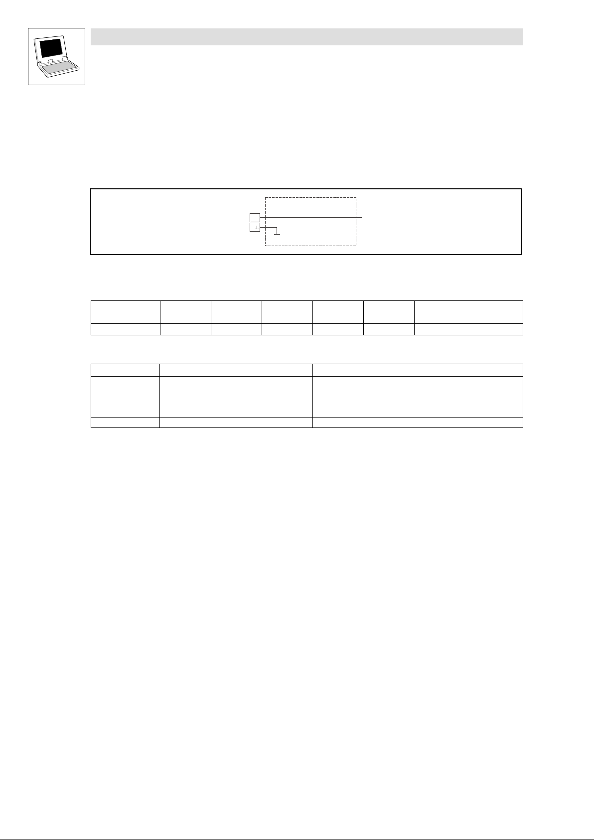
Drive PLC
System blocks − Extension Board 3
7.1 ANALOG4_IO_EB3 (node number 14)
7.1 ANALOG4_IO_EB3 (node number 14)
7.1.1 Inputs_ANALOG4 (analog input 4 of extension board 3)
This SB is the interface for analog signals via terminal AI4, A of the extension board 3.
Fig. 7−1 Inputs_ANALOG4
System variables
Variable Data type Signal type Address Display
AIN4_nIn_a Integer analog %IW14.0 − dec [%] Analog input 4
Terminal assignment
Terminal X2 Use Data
AI4 Analog input 4 Level:
A Internal ground, GND −
Inputs_ANALOG4
AI4
A
AIN4_nIn_a
code
Resolution:
Internal resistance:
Normalisation:
Display
format
−10 V ... +10 V
10 bits + sign
100 k
10 V 16384 100 %
Notes
7−2
DrivePLC DE 6.0
L
Page 71
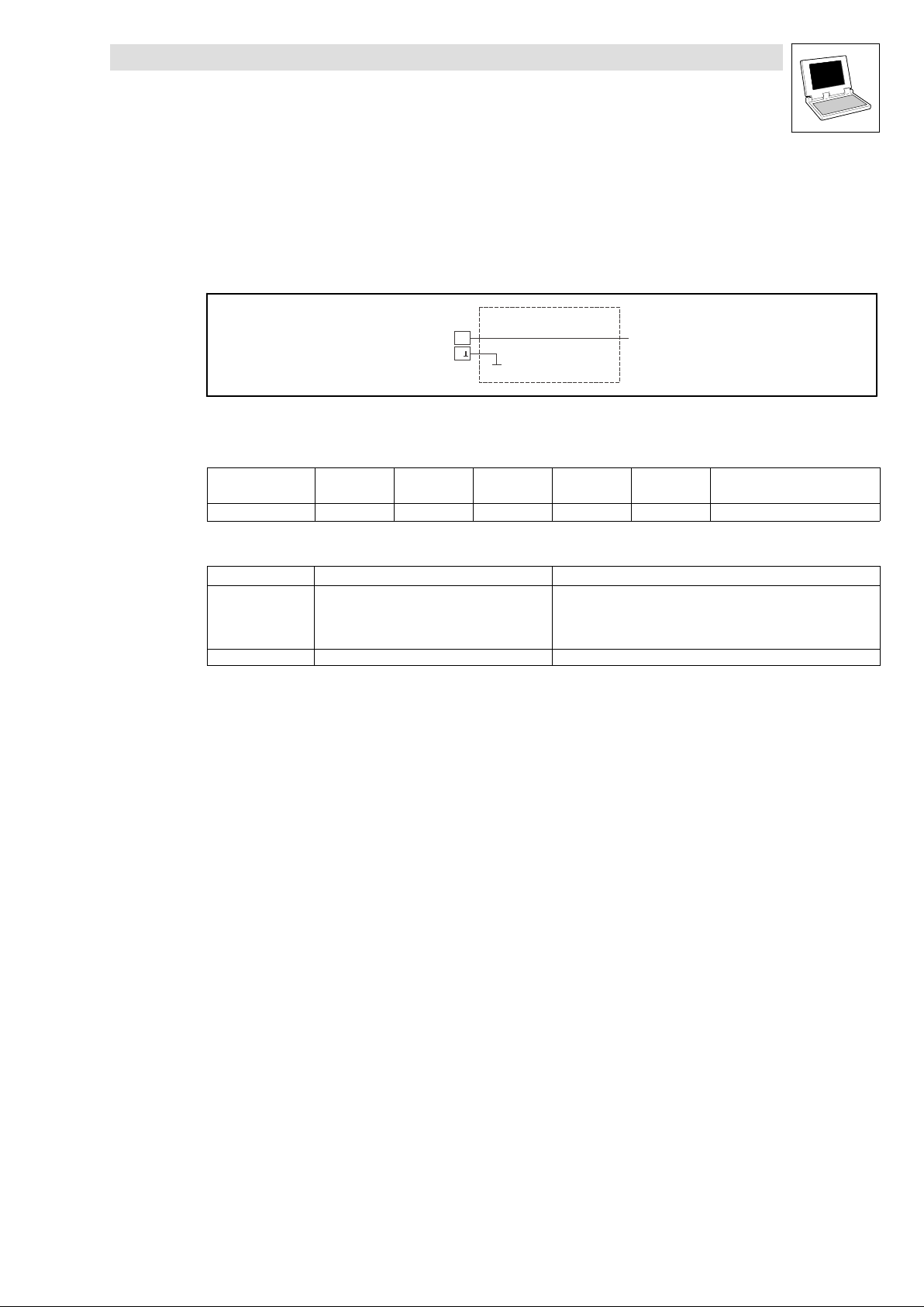
Drive PLC
System blocks − Extension Board 3
7.2 ANALOG5_IO_EB3 (node number 15)
7.2 ANALOG5_IO_EB3 (node number 15)
7.2.1 Inputs_ANALOG5 (analog input 5 of extension board 3)
This SB is the interface for analog signals via terminal AI5, A of the extension board 3.
Fig. 7−2 Inputs_ANALOG5
System variables
Variable Data type Signal type Address Display
AIN5_nIn_a Integer analog %IW15.0 − − Analog input 5
Terminal assignment
Terminal X2 Use Data
AI5 Analog input 5 Level:
A Internal ground, GND −
Inputs_ANALOG5
AI5
A
AIN5_nIn_a
code
Resolution:
Internal resistance:
Normalisation:
Display
format
−10 V ... +10 V
10 bits + sign
100 k
10 V 16384 100 %
Notes
L
DrivePLC DE 6.0
7−3
Page 72
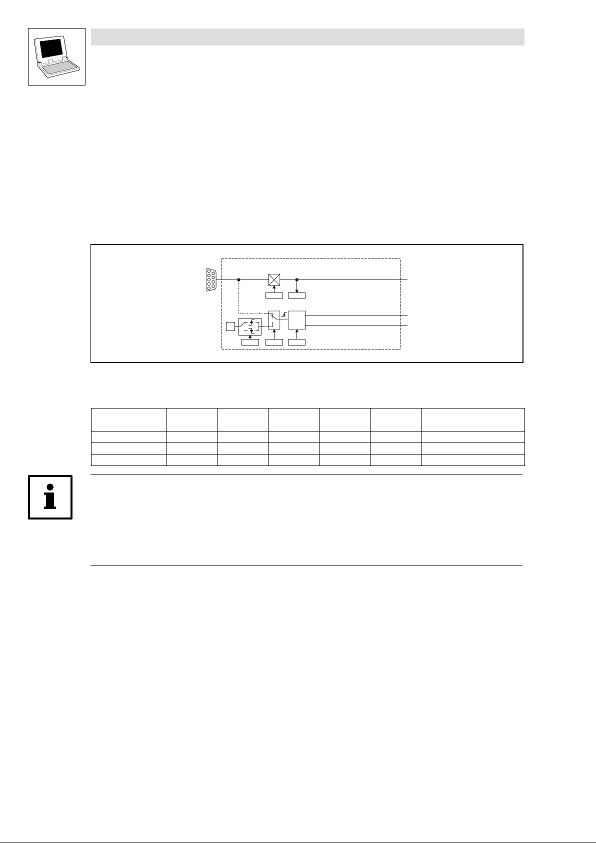
Drive PLC
System blocks − Extension Board 3
7.3 DFIN_IO_DigitalFrequency (node number 21)
7.3 DFIN_IO_DigitalFrequency (node number 21)
7.3.1 Inputs_DFIN (encoder input of extension board 3)
This SB can convert and normalise a pulse current at the encoder input X3 of the extension board
3 into a speed value.
The transmission is very precise without offset and gain errors.
In addition, this SB provides the angle correction value DFIN_dnIncLastScan_p which is
required within the calling task for the angle processing in touch probe processes.
(^ 7−8)
Fig. 7−3 DFIN_IO_DigitalFrequency
System variables
Variable Data type Signal type Address Display
DFIN_nIn_v Integer velocity %IW21.0 C0426 dec [rpm]
DFIN_bTPReceived_b Bool binary %IX21.4.0 − −
DFIN_dnIncLastScan_p Double integer position %ID21.1 − −
Tip!
The process image is newly created for every task the SB is used in.
If DFIN_nIn_v, DFIN_dnIncLastScan_p and DFIN_bTPReceived_b are used in several tasks,
every task gets its own SB process image.
This process is different from the previous process image principle!
X3
C0425
MP
0
I1
1
C0431
0
1
C0428 C0429
DFIN_IO_DigitalFrequency
C0426
TP/MP
-Ctrl
DFIN_bTPReceived_b
DFIN_dnIncLastScan_p
Code
DFIN_nIn_v
Display
Format
Notes
7−4
DrivePLC DE 6.0
L
Page 73
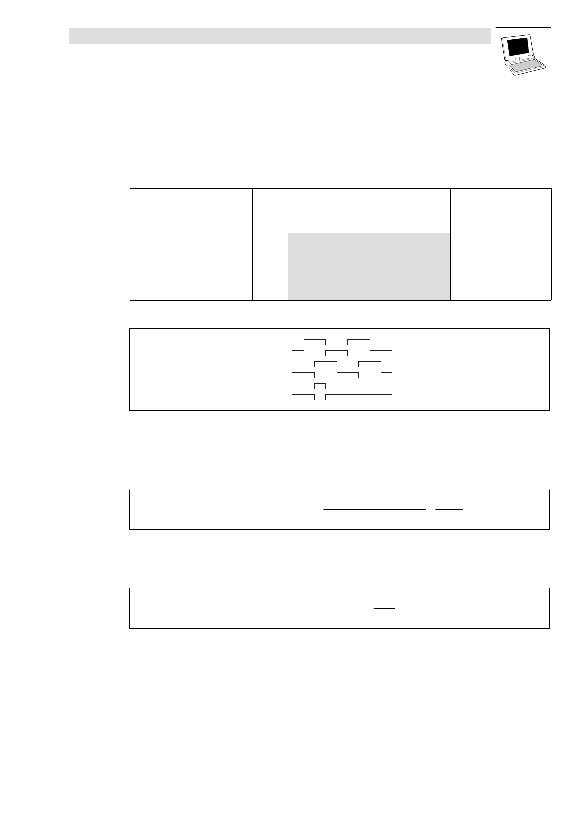
Drive PLC
System blocks − Extension Board 3
7.3 DFIN_IO_DigitalFrequency (node number 21)
7.3.1.1 Encoder input X3
Encoder input X3 of the extension board 3 is designed for signals with TTL level.
The input of a zero track is optional.
The drive can be adapted to the connected encoder or preconnected controller with master
frequency cascade or master frequency bus under C0425.
Code LCD
C0425 DFIN const 3 Extension board 3: DFIN_IO
Possible settings
Lenze Selection
Evaluation of master frequency signals
Fig. 7−4 Signal sequence with phase−shift (CW rotation)
CW rotation: Track A leads track B by 90 ° (positive value at DFIN_nIn_v).
CCW rotation: Track A lags track B by 90 ° (negative value at DFIN_nIn_v).
IMPORTANT
Increments of the encoder input
0 256 inc/rev
1 512 inc/rev
2 1024 inc/rev
3 2048 inc/rev
4 4096 inc/rev
5 8192 inc/rev
6 16384 inc/rev
A
A
B
B
Z
Z
Transmission function
DFIN_nIn_v + f[Hz] @
IncrementsfromC0425
Example:
Input frequency = 200 kHz
C0425 = 3, this corresponds to 2048 increments/rev.
DFIN_nIn_v[rpm] + 200000Hz @
60
60
2048
2
@
15000
+ 5859rpm
14
L
DrivePLC DE 6.0
7−5
Page 74
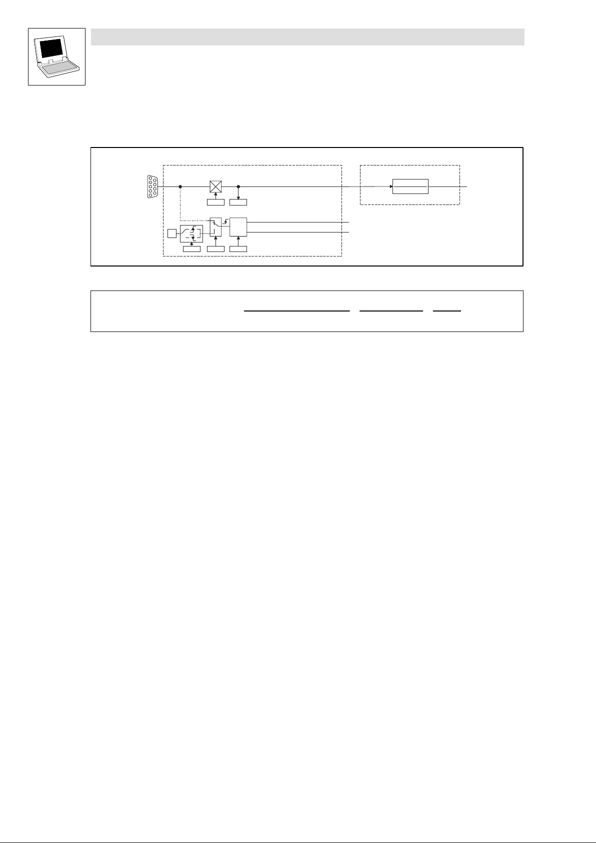
Drive PLC
System blocks − Extension Board 3
7.3 DFIN_IO_DigitalFrequency (node number 21)
Signal adaptation
Finer resolutions can be achieved by adding a following FB (e.g. L_CONVV from LenzeDrive.lib):
L_CONVV3
X3
C0425
MP
0
I1
1
C0431
0
1
C0428 C0429
Fig. 7−5 Encoder input (DFIN_IO_DigitalFrequency) with following FB L_CONVV for normalisation
DFIN_IO_DigitalFrequency
C0426
TP/MP
-Ctrl
DFIN_bTPReceived_b
DFIN_dnIncLastScan_p
DFIN_nIn_v
nIn_v
nNumerator
nDenominator
L_CONVV
nOut_v
nOut_a + f[Hz] @
60
IncrementsfromC0425
nNumerator
@
nDenominator
@
15000
14
2
7−6
DrivePLC DE 6.0
L
Page 75
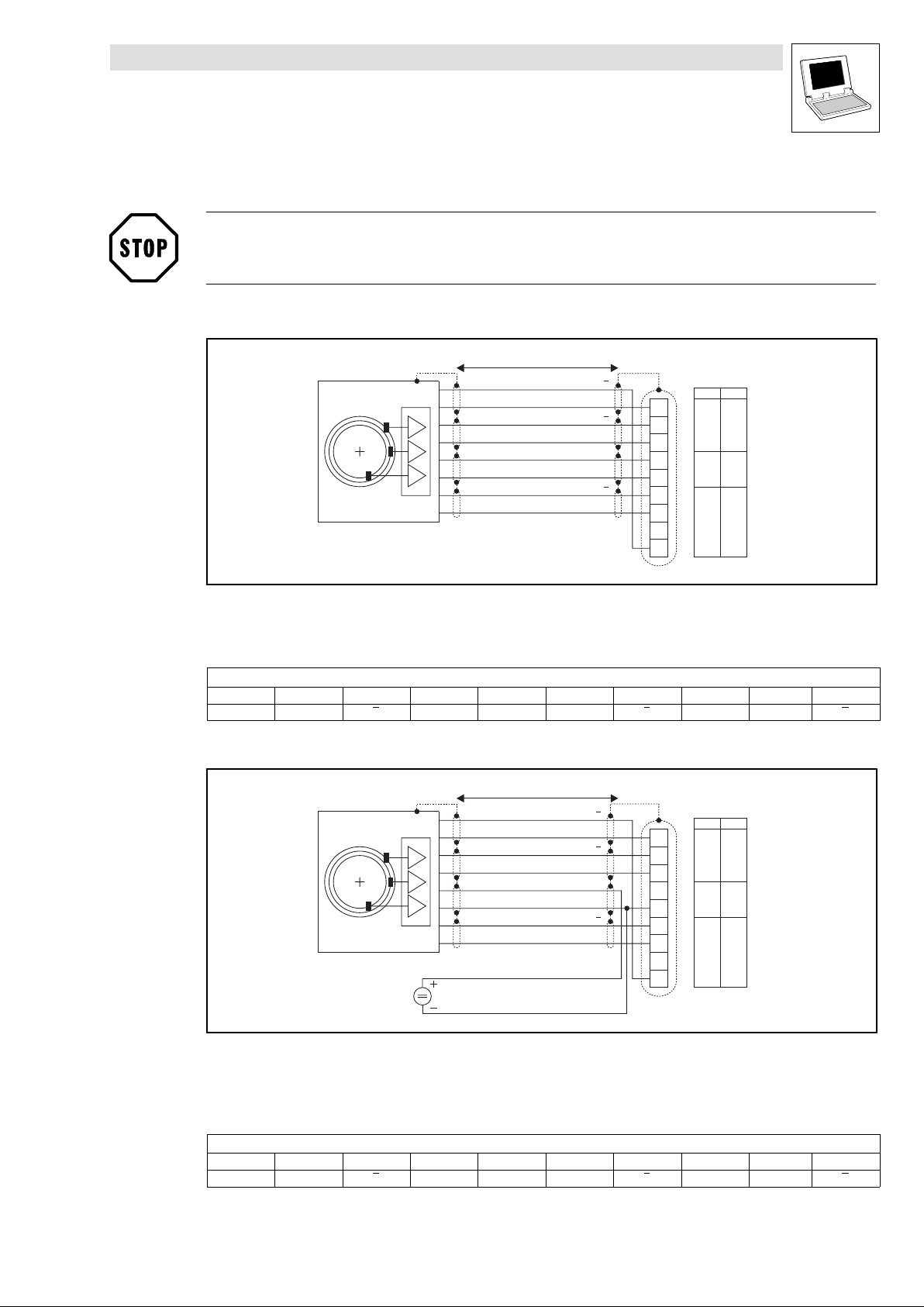
Drive PLC
System blocks − Extension Board 3
7.3 DFIN_IO_DigitalFrequency (node number 21)
7.3.1.2 Connection of incremental encoders to terminal X3
Stop!
Observe connection voltage of the incremental encoder used!
Incremental encoder with TTL level
l = max. 50 m
V
cc5_E
GND
B
B
A
A
Z
Z
X3
mm
1
0.14
2
3
4
5
1.0
6
7
0.14
8
9
2
AWG
26
17
26
Fig. 7−6 Connection of incremental encoder with TTL level to terminal X3
Incremental encoder
Cable cross−sections to be used
Assignment of the Sub−D connector (X3)
PIN 1 2 3 4 5 6 7 8 9
Signal B A A V
cc5_E
Incremental encoder with HTL level
l = max. 50 m
Fig. 7−7 Connection of incremental encoder with HTL level to terminal X3
GND Z Z − B
X3
mm
2
AWG
1
0.14
2
26
3
4
5
1.0
17
6
7
0.14
8
26
V
GND
B
B
A
A
cc5_E
Z
Z
9
L
Incremental encoder
Cable cross−sections to be used
Supply voltage for the incremental encoder
Assignment of the Sub−D connector (X3)
PIN 1 2 3 4 5 6 7 8 9
Signal B A A +5 V GND Z Z − B
DrivePLC DE 6.0
7−7
Page 76
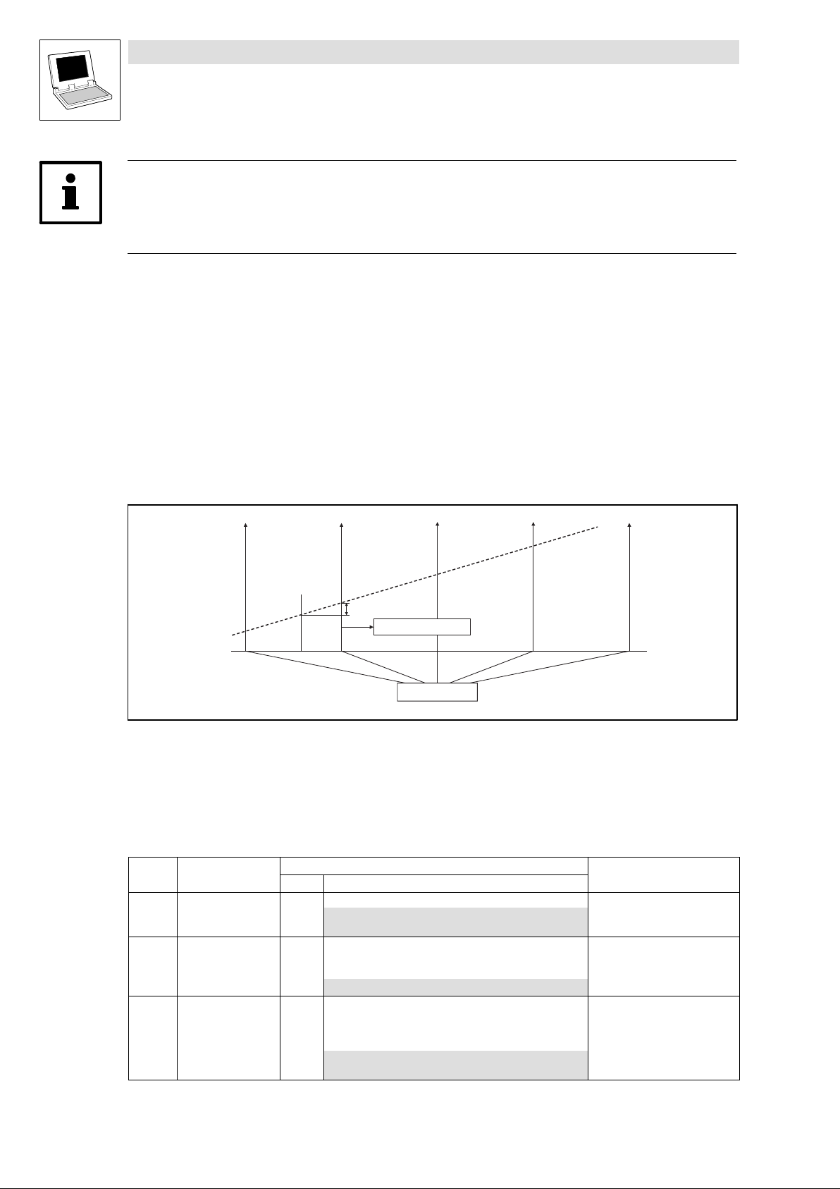
Drive PLC
System blocks − Extension Board 3
7.3 DFIN_IO_DigitalFrequency (node number 21)
Tip!
You can connect incremental encoders with HTL level that supply signals A and B only, to PIN 2 and
PIN 9. The inputs at PIN 3 and PIN 1 must then be connected to the supply voltage of the incremental
encoder.
The connection is as shown in the figures:
Use twisted pair cables and screened pair cables.
Connect the screen at both ends.
Do not change the cable cross−sections indicated.
7.3.1.3 Touch probe (TP)
Process: The current angle value (encoder input value) is saved by a quick interrupt in the operating
system when a signal changes at the TP activating input (e.g. X3/I1).
j
Fig. 7−8 Function chart of a TP
Time−equidistant start of an interval task
Phase−angle signal
Touch probe configuration
Code LCD
C0428 DFIN TP sel. 0 Touch probe selection
C0429 TP delay 0 Touch probe delay
C0431 DFIN TP EDGE 0 Touch probe activation
TP
Possible settings
Lenze Selection
0 Touch probe via zero pulse
1 Touch probe via digital input X3/I1
−32767 {1 inc} 32767
0 Activation with positive signal
1 Activation with negative signal
DFIN_dnIncLastScan_p
IMPORTANT
Compensation of delay times
of TP signal source at X3/I1
For touch probe via digital
input X3/I1
(C0428 = 1)
7−8
DrivePLC DE 6.0
L
Page 77
Drive PLC
System blocks − Extension Board 3
7.3 DFIN_IO_DigitalFrequency (node number 21)
Functional sequence
1. The TP is signal−controlled via the digital input X3/I1 of the basic unit or a zero pulse (only if an
encoder is connected).
2. If a TP has occurred, DFIN_bTPReceived_b is set = TRUE.
3. After the start of the task, DFIN_dnIncLastScan_p indicates the number of increments [inc]
counted since the TP.
4. Following, DFIN_bTPReceived_b = FALSE is set.
Note!
It is necessary that all three outputs (DFIN_nIn_v, DFIN_bTPReceived_b and
DFIN_dnIncLastScan_p) are processed in the task even if just one signal is required.
DFIN_nIn_v
The value DFIN_nIn_v is scaled in increments per millisecond.
(INT) 16384 corresponds to 15000 rpm. See chapter 1.2.7, "Signal types and normalisations".
(^ 1−8)
For every task in which DFIN_nIn_v is used, the operating system creates an individual counter
that is reset after every start of the task (task−internal process image).
For reliable TP generation, DFIN_nIn_v must not be used in the PLC_PRG.
Example (DFIN_nIn_v in a 10 ms task):
When the 10 ms task starts, the value of the integrator is stored in a local area of the task and
the integrator is reset. The value in the local area gives an average value in increments per 1
ms.
If a position value is to be derived from this value, then it must be multiplied by
SYSTEM_nTaskInterval / 4 to get the result in increments per 10 ms, as in the example.
Example: In a 1 ms task SYSTEM_nTaskInterval is 4 (4 x 250 s = 1 ms)
For Lenze FBs, this process has already been implemented in the FBs.
L
DrivePLC DE 6.0
7−9
Page 78
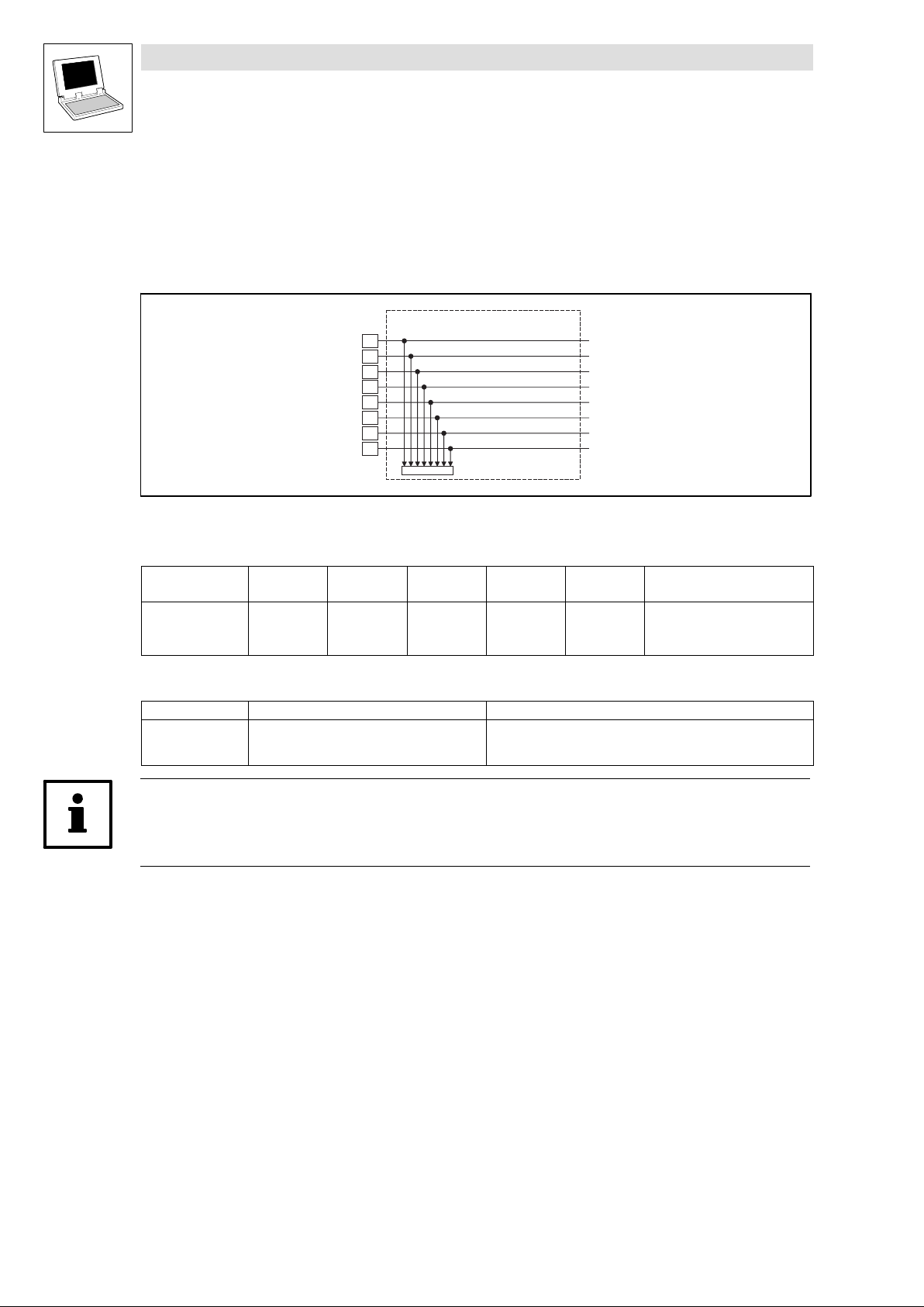
Drive PLC
System blocks − Extension Board 3
7.4 DIGITAL_IO_EB3 (node number 4)
7.4 DIGITAL_IO_EB3 (node number 4)
7.4.1 Inputs_DIGITAL_EB3 (digital inputs, extension board 3)
This SB reads the signals at terminals I9 ... I16 of the extension board 3 and conditions them.
Fig. 7−9 Inputs_DIGITAL_EB3
System variables
Variable Data type Signal type Address Display
DIGIN_bIn9_b
... ... ...
DIGIN_bIn16_b %IX4.0.7 C0446/1−bit8
Electrical data of the input terminals
Terminal Use Data
I9
...
I16
I9
I10
I11
I12
I13
I14
I15
I16
Bool binary
freely assignable
Inputs_DIGITAL_EB3
C0446/1
code
%IX4.0.0 C0446/1−bit1
LOW level:
HIGH level:
Input current:
DIGIN_bIn9_b
DIGIN_bIn10_b
DIGIN_bIn11_b
DIGIN_bIn12_b
DIGIN_bIn13_b
DIGIN_bIn14_b
DIGIN_bIn15_b
DIGIN_bIn16_b
Display
format
bin
0 ... +4 V
+13 ... +30 V
8 mA per input (at 24 V)
Notes
Tip!
Detailed information about the terminal assignment for the extension board 3 can be found in the
corresponding Mounting Instructions!
7−10
DrivePLC DE 6.0
L
Page 79
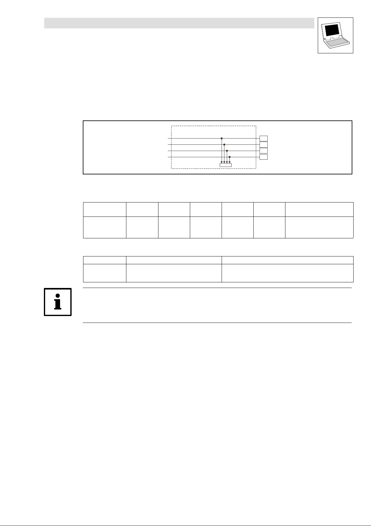
Drive PLC
System blocks − Extension Board 3
7.4 DIGITAL_IO_EB3 (node number 4)
7.4.2 Outputs_DIGITAL_EB3 (digital outputs, extension board 3)
This SB conditions the digital signals and outputs them at terminals O5 ... O8 of the extension board
3.
Fig. 7−10 Outputs_DIGITAL_EB3
System variables
Variable Data type Signal type Address Display
DIGOUT_bOut5_b
... ... ...
DIGOUT_bOut8_b %QX4.0.3 C0448 − bit4
Electrical data of the output terminals
Terminal Use Data
O5
...
O8
Tip!
Detailed information about the terminal assignment for the extension board 3 can be found in the
corresponding Mounting Instructions!
DIGOUT_bOut5_b
DIGOUT_bOut6_b
DIGOUT_bOut7_b
DIGOUT_bOut8_b
Bool binary
freely assignable
Outputs_DIGITAL_EB3
C0448
code
%QX4.0.0 C0448 − bit1
LOW level:
HIGH level:
Output current:
O5
O6
O7
O8
Display
format
bin
0 ... +4 V
+13 ... +30 V
max. 1 A per output
Notes
L
DrivePLC DE 6.0
7−11
Page 80

Drive PLC
System blocks − Extension Board 3
7.4 DIGITAL_IO_EB3 (node number 4)
7−12
DrivePLC DE 6.0
L
Page 81
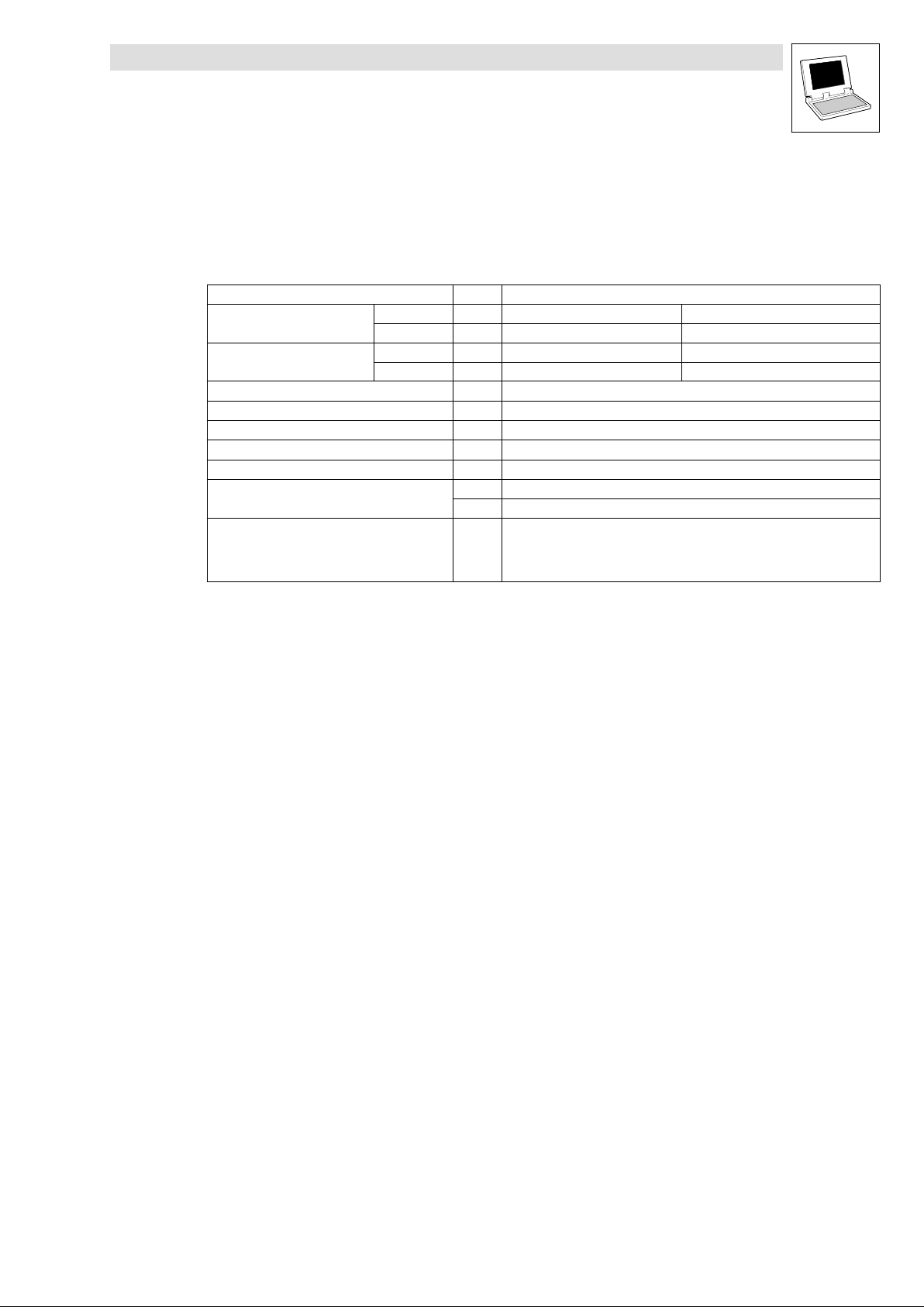
Drive PLC
Appendix
8.1 PLC functionality
8 Appendix
8.1 PLC functionality
Field Number Description
Inputs
Outputs
Operation set According to IEC61131−3
Counter/times According to IEC61131−3, depending on the data memory available.
Flags 1000 Flag words
Memory See chapter 8.3 (^ 8−4)
Processing time (1−bit operation) 1 s
Task types
Programming software Drive PLC Developer Studio
digital 8 Free inputs (3 of them interruptible) 24 V DC / 8 mA each input
analog 3 Free inputs (10 bit + sign) 10 V
digital 4 Free outputs 24 V DC / max. 1 A each output
analog 1 Free output (10 bit + sign) 10 V / max. 2 mA
8 Time or event−controlled tasks (1 ms ... 16 s)
1 Cyclic task
Programming languages according to IEC61131−3 standard (IL, LD, FBD, ST,
SFC) as well as CFC editor
Monitoring, visualisation, simulation and debugging
L
DrivePLC DE 6.0
8−1
Page 82
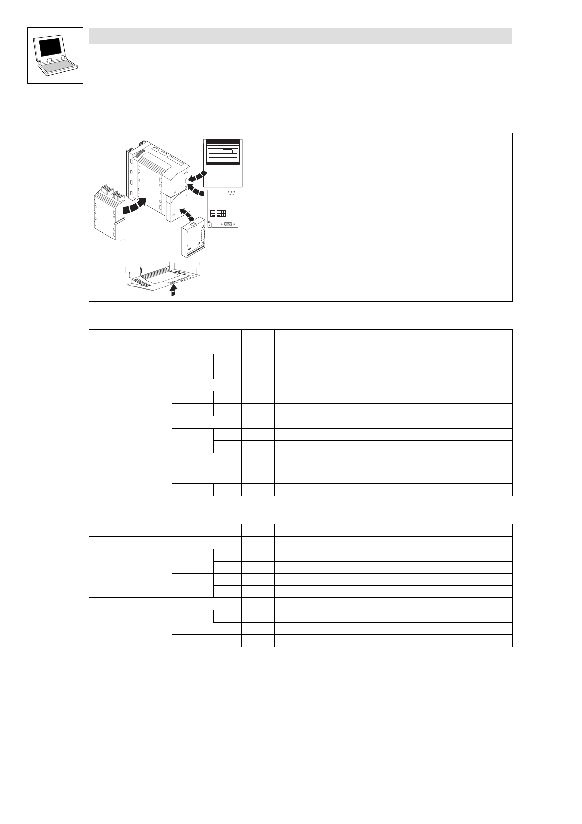
Drive PLC
Appendix
8.2 Extendability/networking
8.2 Extendability/networking
Extension boards
Extension Board 1
Extension Board 2
extension board 3
GLOBAL DRIVE
dcbB
SHPRG
p
PaR2 PaRa
125 rpm0
MCTRL-N-ACT
z
Y
Z
y
59 39
71
0051
T
S
l
LECOMA/B
88
72
89
Automation interface (AIF)
A
00
for keypad and the following AIF modules:
2102 LECOM−A/B/LI
V
U
2103 FP interface (RS−232C)
2111 INTERBUS
2112 INTERBUS−Loop
2133 PROFIBUS−DP
2174 CAN addressing module
2175 DeviceNet / CANopen
Others in preparation
Plug−in station for extension boards
Function interface (FIF)
for FIF modules
Integrated system bus interface
(Terminal X5 at the bottom of the Drive PLC)
Inputs/outputs Number Description
Inputs digital 6 Free inputs 24 V DC / 8 mA each input
Outputs digital 6 Free outputs 24 V DC / max. 1 A each output
Inputs digital 14 Free inputs 24 V DC / 8 mA each input
Outputs digital 8 Free outputs 24 V DC / max. 1 A each output
Inputs
digital 6 Free inputs 24 V DC / 8 mA each input
analog 2 Free inputs (10 bit + sign) 10 V
1 Encoder input Frequency range:
HTL 0 ... 200kHz, TTL 0 ... 500kHz
(TTL/HTL level)
Outputs digital 6 Free outputs 24 V DC / max. 1 A each output
Modules for function interfaces (FIF)
Inputs/outputs Number Description
Standard I/O FIF module
Inputs
Outputs
CAN−I/O FIF module
Inputs
Outputs System bus (CAN)
digital 5 Free inputs 24 V DC / 8 mA each input
analog 1 Free input (10 bit + sign) 10 V
digital 1 Free output 24 V DC / max. 1 A
analog 1 Free output (10 bit + sign) 10 V / max. 2 mA
digital 1 Free input 24 V DC / 8 mA
3 System bus (CAN), free inputs
8−2
DrivePLC DE 6.0
L
Page 83
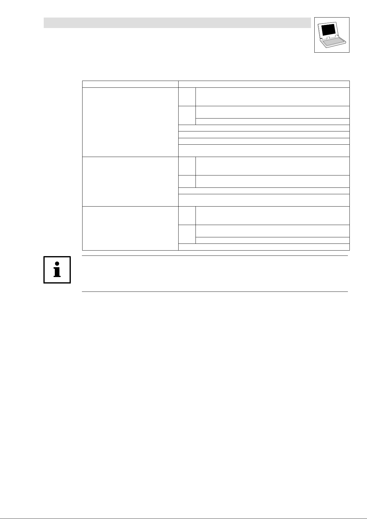
Drive PLC
Appendix
8.2 Extendability/networking
System bus (CAN)
Interface Available CAN objects
Integrated system bus interface
Automation interface (AIF)
with corresponding fieldbus module
(e.g. 2175)
Function interface (FIF)
with corresponding function module
(e.g. CAN−I/O system bus)
PDOs CAN1_IN/CAN1_OUT
CAN2_IN/CAN2_OUT
CAN3_IN/CAN3_OUT
SDOs
SDO1 (parameter data channel 1)
SDO2 (parameter data channel 2)
L_ParRead/L_ParWrite functionality
Sync telegram
Synchronisation of the internal time basis by receiving sync telegrams
Free CAN objects
CanDSx driver for mapping indices to codes and for bus monitoring functions "Heartbeat"
and "Node Guarding" (see Manual "Function library LenzeCanDSxDrv.lib").
PDOs XCAN1_IN/XCAN1_OUT
XCAN2_IN/XCAN2_OUT
XCAN3_IN/XCAN3_OUT
SDOs XSDO1 (parameter data channel 1)
XSDO2 (parameter data channel 2)
XSync telegram
AifParMap driver for mapping code accesses via AIF to other codes (see Manual "Function
library LenzeAifParMapDrv.lib").
PDOs FIF−CAN1_IN/FIF−CAN1_OUT
FIF−CAN2_IN/FIF−CAN2_OUT
FIF−CAN3_IN/FIF−CAN3_OUT
SDOs
FIF−SDO1 (parameter data channel 1)
FIF−SDO2 (parameter data channel 2)
L_ParRead/L_ParWrite functionality
Sync telegram
Tip!
Detailed information about the system bus (CAN) can be found in the Manual "System bus (CAN) for
Lenze PLCs"
L
DrivePLC DE 6.0
8−3
Page 84
Drive PLC
Appendix
8.3 Memories
8.3 Memories
The below table gives you an overview of the memories available:
Memory Size Info
ROM
Program memory 256 kbytes Re−written whenever the program is downloaded.
RAM
PLC data memory
Application data memory 2 blocks
E2PROM−buffered memory
Retain memory 200 bytes See subsection 8.3.1
Tip!
Function library LenzeMemDrv.lib includes functions for read/write access to the additional backup
memory (application data memory) of the PLC.
Additional information can be found in the Manual for function library LenzeMemDrv.lib.
10 kbyte
24 kbytes
(as of version 7.x)
à 64 kbytes
Can be symbolically used for FB instances and PLC variables.
Data get lost after mains disconnection.
8.3.1 Retain memory
In the retain memory the values of the retain variables are stored safe from power failure and are thus
available to the program even after mains switching. (Saving with C0003 = 1 is not required.)
Retain variables are declared by means of the variable class VAR RETAIN.
Retain variables are created as a symbolically addressable memory.
With each program download the retain variables are reset to their initialisation value. If an
initialisation value has not been defined, the corresponding retain variable will be initialised
with the value "0".
In the DDS online mode you can use the commands Online W Reset (cold) and Online W
Reset (original) to reset the retain variables in the PLC to their initialisation values.
8.3.2 Downloading data
In DDS (as of version 2.0) it is possible to attach a file to your project whose data is automatically
downloaded to the PLC when the program is downloaded.
This mechanism is, for instance, used in the Software Package − Cam to download motion
profiles.
Note!
With the 9300 Servo PLC the additional data is loaded into the application FLASH.
With the Drive PLC the additional data is directly attached to the PLC program because the
Drive PLC does not have an application FLASH.
8−4
DrivePLC DE 6.0
L
Page 85
Drive PLC
Appendix
8.3 Memories
For the download being executed by the DDS, the following two conditions must be met:
1. The PLC program must have been stopped.
2. The header of the file attached to the project must have the following structure:
Name Data type Data length in bytes Contents
wSizeHeader WORD 2 Header length in bytes
wDataType WORD 2 Data specification identifier
dwVersion DWORD 4 Data version
dwRealSize DWORD 4 User data length in bytes (without header)
dwTimeStamp DWORD 4 Time stamp of the last data change
wLicenseInfo WORD 2 Reserved for future extensions
wSizeSymbolicName WORD 2 Length of the symbolic file name
achSymbolicName ACH wSizeSymbolicName Character array including the symbolic file name
wCopyToRam WORD 2 Selection whether data will be automatically copied into the application RAM of
dwReserved DWORD 4
awSizeAddInfo DWORD 190
Interpretation of the header information: least significant byte first:
This information can be found under C2131 after data has been downloaded.
0 ... 10000 Lenze−spezific data
> 10000 User data
This information can be found under C2132 after data has been downloaded.
This information can be found under C2133 after data has been downloaded.
This information can be found under C2130 after data has been downloaded.
the PLC after downloading.
Maximum data length = 128 kbytes (RAM block 1 and 2)
0 Data is not copied into the application FLASH.
1 Data is copied into the application FLASH.
2 ... 65535 Reserved
Reserved for future extensions
wSizeHeader = 00 E4 = 228 Byte
wDataType = 00 0A = 10 (Cam data)
hex
hex
dwVersion =00000001
hex
E4 00 0A 00 01 00 00 00 1C FF 00 00
dwRealSize = 00 00 FF 1C = 65308 Byte
hex
L
DrivePLC DE 6.0
8−5
Page 86
Drive PLC
Appendix
8.4 System POUs
8.4 System POUs
System POUs are POUs of the "program" type which accept the features of a certain name, i.e. they
are started by an event registered by the PLC.
The program includes max. 1000 instructions for system POUs.
Unlike tasks or PLC_PRG, system POUs are not run−time monitored by a "watchdog".
The special POU names and the corresponding event for starting the POU are listed in the
following table:
POU name Event for starting POU The POU starts if
PLC_TaskOverrun Task overflow
PLC_RealError Floating−point error ...a floating−point error occurs.
PLC_FailTripping TRIP ...a trip is set.
PLC_WarningTripping Warning ...a warning is activated.
PLC_MessageTripping Message ...a message is activated.
PLC_FailQspTripping FAIL−QSP ...a FAIL−QSP is activated.
PLC_CANError CAN bus error ...a CAN bus error occurs (e.g. BUS−OFF).
PLC_AIFError AIF bus error ...an AIF bus error occurs.
PLC_Restart Start ...the START command is activated after a STOP.
PLC_ColdStart Cold start ...a RESET, RESET (cold), RESET (original) or a program download has been
PLC_Stop PLC stop ...the STOP command is activated.
...the task monitoring time is exceeded.
1)
1)
Note: Only called when pulse inhibit is inactive!
activated.
Note: System variables must not be used in PLC_ColdStart. Otherwise, unexpected
controller errors may occur (e.g. motor start).
Note: This POU is not activated through a RESET (cold, original)!
1)
Not available for Drive PLC.
2)
The CAN/AIF bus is ready after this POU has been executed.
2)
Tip!
If you need a system POU for an event−controlled start, simply create a "program" POU and use the
POU name listed in the table for the corresponding event as POU name.
8−6
DrivePLC DE 6.0
L
Page 87
Drive PLC
Appendix
8.5 System error messages
8.5 System error messages
The history buffer (C0168/x) stores error messages with an offset which indicates the type of response:
Error message number Type of response
0xxx TRIP
1xxx Message
2xxx Warning
3xxx FAIL−QSP
Example: C0168/1 = 2061
x061:
The current error (subcode 1 of C0168) is a communication error (error message "CE0"/no.
"x061") between AIF module and PLC.
2xxx:
The response is a warning.
The current error number is also indicated in the variable DCTRL_wFaultNumber of the PLC program.
Tip!
Errors generally do not influence the operability of the PLC!
L
DrivePLC DE 6.0
8−7
Page 88
Drive PLC
Appendix
8.5 System error messages
8.5.1 Overview of system error messages, error sources and reactions
System error message Possible settings/response
No. Display Source Meaning
x011 OC1 MCTRL Motor cable short circuit ü ü
x012 OC2 MCTRL Motor cable earth fault ü ü
x015 OC5 MCTRL I x t overload ü ü
x016 OC6 MCTRL I2 x t overload (C0120) ü
x017 OC7 MCTRL I x t warning (C0123) C0604 ü ü ü
x018 OC8 MCTRL I2 x t warning (C0127) C0605 ü ü ü
x020 OU MCTRL Overvoltage in the DC bus ü ü
x030 LU MCTRL Undervoltage in the DC bus ü ü
x032 LP1 MCTRL Motor phase failure C0597 ü ü ü ü
x050 OH MCTRL Heat sink temperature higher than fixed limit
temperature
x051 OH1 MCTRL Temperature inside the controller > 90° C ü
x053 OH3 MCTRL Motor temperature higher than fixed limit tem-
perature
x054 OH4 MCTRL Heat sink temperature higher than variable li-
mit temperature (C0122)
x055 OH5 MCTRL Temperature inside the controller > C0124 C0605 ü ü ü
x057 OH7 MCTRL Motor temperature higher than variable limit
temperature (C0121)
x058 OH8 MCTRL Motor temperature via inputs T1/T2 too high C0585 ü ü ü ü
x061 CE0 AIF Communication error between AIF mo-
duleóPLC
Lenze setting ü setting possible
Code TRIP Message Warning FAIL−
ü ü
C0583 ü ü ü
C0582 ü ü ü
C0584 ü ü ü
C0126 ü ü ü ü ü
QSP
Available in
Off Drive
PLC
Servo
PLC
ECSxA
CAN communication error:
x062 CE1 CAN1 CAN1_IN (monitoring time can be set under
x063 CE2 CAN2 CAN2_IN (monitoring time can be set under
x064 CE3 CAN3 CAN3_IN (monitoring time can be set under
x065 CE4 CAN CAN BUS−OFF status
x066 CE5 CAN CAN time−out (gateway function C0370) C0603 ü ü ü ü ü
x070 U15 internal Undervoltage of internal 15 V voltage supply ü ü ü
x071 CCr internal Internal error
x072 PR1 internal Check sum error in parameter set 1 ü ü ü
x074 PEr internal Program error
x075 PR0 internal General error in the parameter sets
x076 PR5 internal Error saving parameters ü ü
x079 PI internal Error during parameter initialisation
x080 PR6 internal Too many user codes ü ü ü
x082 Sd2 MCTRL Resolver error C0586 ü ü ü ü
x083 Sd3 MCTRL Encoder error at X9 PIN 8 C0587 ü ü ü
x085 Sd5 MCTRL Encoder error at analog input (X6) (C0034 = 1) C0598 ü ü ü ü
x086 Sd6 MCTRL Sensor error: motor temperature (X7 or X8) C0594 ü ü ü ü
x087 Sd7 MCTRL Absolute−value encoder error at X8
x088 Sd8 MCTRL Absolute−value encoder error at X8
C0357/1)
C0357/2)
C0357/3)
(too many faulty telegrams received)
1)
1)
1)
1)
1)
1)
C0591
C0592
C0593
C0595 ü ü ü ü ü
C0025 ü ü
C0580 ü ü ü
ü ü ü ü ü
ü ü ü
ü ü ü
ü ü ü
ü ü ü
x: 0 = TRIP, 1 = Message, 2 = Warning, 3 = FAIL−QSP
1)
After error correction: completely deenergise the device!
8−8
DrivePLC DE 6.0
L
Page 89
Drive PLC
Appendix
8.5 System error messages
System error message Possible settings/response
No. Display Source Meaning
x089 PL MCTRL Error during rotor position adjustment ü ü
x091 EEr FWM External monitoring activated via DCTRL C0581 ü ü ü ü ü ü
x105 H05 internal Internal error (memory) ü ü ü
x107 H07 internal Internal error (power stage) ü ü
x108 H08 internal Extension board not connected correctly or not
x110 H10 FWM Temperature sensor error: heatsink tempera-
x111 H11 FWM Temperature sensor error: temperature inside
x122 CE11
x123 CE12
x124 CE13
x125 CE14
x126 CE15 FIF−CAN Communication error of the gateway function
FIF−CAN1 FIF−CAN1_IN (monitoring time can be set under
CANaux1 CANaux1_IN (monitoring time can be set under
FIF−CAN2 FIF−CAN2_IN (monitoring time can be set under
CANaux2 CANaux2_IN (monitoring time can be set under
FIF−CAN3 FIF−CAN3_IN (monitoring time can be set under
CANaux3 CANaux3_IN (monitoring time can be set under
FIF−CAN FIF−CAN BUS−OFF status
FIF−CAN FIF−CAN BUS−OFF status
supported by program
ture
the controller
FIF−CAN / CAN−AUX communication error:
C2457/1)
C2457/1)
C2457/2)
C2457/2)
C2457/3)
C2457/3)
(too many faulty telegrams received)
(too many faulty telegrams received)
(C0370, C0371) via FIF−CAN
Lenze setting ü setting possible
Code TRIP Message Warning FAIL−
ü ü
C0588 ü ü ü
ü ü ü
C0591 ü ü ü
C2481 ü ü ü
C0592 ü ü ü
C2482 ü ü ü
C0593 ü ü ü
C2483 ü ü ü
C0595 ü ü ü
C2484 ü ü ü
C2485 ü ü ü
QSP
Available in
Off Drive
PLC
Servo
PLC
ECSxA
x190 nErr MCTRL Speed out of tolerance margin (C0576) C0579 ü ü ü ü ü ü
x200 NMAX MCTRL Maximum speed exceeded (C0596) ü ü
Time−out (see task configuration):
x201 overrun Task1
x202 overrun Task2 Task with ID 3
x203 overrun Task3 Task with ID 4
x204 overrun Task4 Task with ID 5
x205 overrun Task5 Task with ID 6
x206 overrun Task6 Task with ID 7
x207 overrun Task7 Task with ID 8
x208 overrun Task8 Task with ID 9
x219 overrun Cycl.−T internal Time−out in cyclic task (PLC_PRG, ID 1)
x: 0 = TRIP, 1 = Message, 2 = Warning, 3 = FAIL−QSP
2)
In DDS adjustable under Project W Exception response
internal
Task with ID 2
2)
ü ü ü ü ü
2)
ü ü ü ü ü
L
DrivePLC DE 6.0
8−9
Page 90
Drive PLC
Appendix
8.5 System error messages
System error message Possible settings/response
No. Display Source Meaning
Floating−point error (REAL) in:
x209 FLOAT SYS−T
x210 FLOAT CYCL.−T Cyclic task (PLC_PRG, ID 1)
x211 float T Id2 Task with ID 2
x212 float T Id3 Task with ID 3
x213 float T Id4 Task with ID 4
x214 float T Id5 Task with ID 5
x215 float T Id6 Task with ID 6
x216 float T Id7 Task with ID 7
x217 float T Id8 Task with ID 8
x218 float T Id9 Task with ID 9
x220 NoT−FktCredit internal Not enough technology units available in the
x230 No Program internal No PLC program loaded in PLC ü ü ü
x231 Unallowed Lib internal A library function has been called in the PLC
x232 NoCamData internal Motion profiles (cam data) are not available ü ü ü
x240 ovrTransQueue
x241 ovr Receive Too many receive telegrams C0609 ü ü ü
internal
Free CAN
obj.
System task
PLC
program which is not supported
Free CAN objects:
Overflow of send order memory C0608 ü ü ü
Lenze setting ü setting possible
Code TRIP Message Warning FAIL−
2)
ü ü ü ü ü
ü ü ü
ü ü ü
QSP
3)
Available in
Off Drive
ü ü ü ü
PLC
Servo
PLC
ECSxA
Application memory (FLASH):
x250 2.Flash Err internal Access not possible
x251 AddData CsErr internal Check sum error occurred when loading data
x252 AddData DlErr internal Error occurred when downloading data into the
x260 Err NodeGuard Node
x: 0 = TRIP, 1 = Message, 2 = Warning, 3 = FAIL−QSP
1)
After error correction: completely deenergise the device!
2)
In DDS adjustable under Project W Exception response
3)
Only with 9300 Servo PLC!
guarding
(FLASH memory defective or not available)
into the FLASH memory
FLASH memory (e.g. time−out)
"Life guarding event": The PLC as a CAN slave
has not received any "node guarding" telegram
within the node lifetime of the CAN master.
1)
ü
C0384 ü ü ü
3)
ü ü ü ü
8−10
DrivePLC DE 6.0
L
Page 91
Drive PLC
Appendix
8.5 System error messages
8.5.2 Response and its effects on the drive
Response ð Effect
TRIP o n n
TRIP active: ð The power outputs U, V, W are switched to high resistance.
ð The drive is coasting (no control!).
TRIP reset: ð The drive accelerates to its setpoint along the set ramps.
Message o n n
The drive restarts automatically when the message is no longer active!
Message active: ð The power outputs U, V, W are switched to high resistance.
0.5 s ð The drive is coasting (no control!).
0.5 s ð The drive is coasting (due to internal controller inhibit!). If necessary, restart program.
Message reset: ð The drive accelerates at the maximum torque to its setpoint.
Warning n o n
Deactivated monitoring functions can lead to the destruction of the drive!
ð The failure is only displayed, the drive continues running in a controlled mode.
FAIL−QSP − − −
ð The drive is decelerated to standstill along the QSP ramp (C0105).
Off − − −
Deactivated monitoring functions can lead to the destruction of the drive!
ð No failure response!
Operating unit display
RDY IMP FAIL
o = off n = on
8.5.3 System error message reset
Response Measures to reset system error messages
TRIP/FAIL−QSP
Message
Warning The message automatically disappears after the error has been eliminated.
A reset of TRIP/FAIL−QSP requires an acknowledgement.
If the TRIP source is still active, the current TRIP cannot be reset.
A TRIP/FAIL−QSP can be acknowledged by:
Keypad ðPressing the STOP key before the RUN key (which enables the PLC again).
Code C0043 ðSet C0043 = 0
The message automatically disappears after the error has been eliminated, the drive automatically restarts!
L
DrivePLC DE 6.0
8−11
Page 92
Drive PLC
Appendix
8.5 System error messages
8.5.4 Cause & remedy
No. Display Meaning Cause Remedy
−−− −−− No error − −
061 CE0 Communication error
AIF moduleóBasic unit
062 CE1 CAN1_IN communication error
063 CE2 CAN2_IN communication error
064 CE3 CAN3_IN communication error
065 CE4 CAN BUS−OFF status
(too many faulty telegrams
received)
066 CE5 CAN time−out
(gateway function)
070 U15 Undervoltage of internal 15 V
voltage supply
071 CCR Internal error The program sequence of the processor was
072 PR1 Check sum error
in parameter set 1
CAUTION:
Lenze setting is loaded
automatically!
074 PEr Program error Error detected in program Check use of pointers
075 PR0 General error in parameter sets
CAUTION:
Lenze setting is loaded
automatically!
076 PR5 Error while saving parameters Error while saving parameters in the fail−safe
079 PI Error during
parameter initialisation
080 PR6 Too many user codes Reduce the number of user codes
x09 EEr External monitoring activated
via DCTRL
105 H05 Internal error (memory) Contact Lenze
108 H08 Extension board error
122 CE11 Communication error
FIF−CAN1_IN
123 CE12 Communication error
FIF−CAN2_IN
124 CE13 Communication error
FIF−CAN3_IN
Interference during transfer of control commands
via automation interface (AIF)
CANx_IN receives faulty data or communication
interrupted
Plug in automation module firmly, bolt down, if
necessary
Check wiring/cable
Check transmitter
If possible, increase monitoring time under
C0357/x
PLC has received too many faulty telegrams sent
via system bus and has disconnected itself from
the bus
Check wiring/cable
Check bus termination (if any)
Check screen contact of the cables
Check PE connection
Check bus load
Reduce baud rate (observe cable length)
For remote parameterisation via system bus
(C0370):
Check system bus wiring/cable
Check system bus configuration
Slave does not respond
Communication monitoring time exceeded
Check voltage supply for Drive PLC
Shield control and motor cables as necessary
interfered
Error while loading a parameter set
Interruption of parameter set transfer via
keypad (e.g. by disconnection of the keypad)
Check PE wiring and PE connections
Set the desired parameters and save them
under C0003
For PR0 the supply voltage must be switched
off additionally
Check use of pointers
The saved parameters do not match the loaded
software version
Before an error can be acknowledged, the
parameter set must be manually saved under
C0003
Send controller with parameter set and PLC
program (on diskette) to Lenze
See Cause & Remedy, no. 072 (PR1)
memory area
Error detected during parameter set transfer
between two controllers
Contact Lenze
Correct the parameter set
Check code initialisation values
Parameter set does not match the PLC or
controller (e.g. data transfer from a
high−performance controller to a
lower−performance controller)
A digital signal assigned to the TRIP−SET function
has been activated (system block DCTRL is
integrated as of software version V8.0)
Extension board not connected correctly Connect extension board properly
Check external encoder
Deactivate monitoring (C0581 = 3)
Check connection plug EBóPLC
Extension board is not supported by PLC program Adapt PLC program to extension board
Use extension board which is supported by PLC
program.
FIF−CANx_IN receives faulty data or
communication interrupted
Check wiring/cable
Check transmitter
If possible, increase monitoring time under
C2457/x
8−12
DrivePLC DE 6.0
L
Page 93
Drive PLC
Appendix
8.5 System error messages
No. RemedyCauseMeaningDisplay
125 CE14 FIF−CAN BUS−OFF status
201
oveR−RUN TASK1
...
...
208
oveR−RUN TASK8
209 FLOAT SYS−T System task
210 FLOAT CYCL.−T Cyclic task (PLC_PRG)
211
FLOATTASK1
...
...
218
FLOATTASK8
219 overrun Cycl.−T Time−out in
220 NoT−FKT−CREDIT Insufficient units on the target
230 No Program PLC program error No PLC program loaded Load PLC program to PLC
231 Unallowed Lib Library function is not
232 NoCamData Motion profiles (cam data) are
240 ovrTransQueue Error Free CAN objects" Overflow of send order memory Reduce number of send orders
241 ovr Receive Error Free CAN objects" Too many receive telegrams Reduce number of telegrams on bus
250 2.Flash Err Error during FLASH memory
251 AddData CsErr Error during FLASH memory
252 AddData DlErr Error during FLASH memory
260 Err NodeGuard "Life guarding event" PLC has been configured as a CAN slave with
(too many faulty telegrams
received)
Task with Id.2
...
Task with Id.9
Task with Id.2
...
Task with Id.9
cyclic task (PLC_PRG)
system
supported
not available
access
access
access
PLC has received too many faulty telegrams sent
via system bus and has disconnected itself from
the bus
Time−out (see task configuration):
Task processing takes longer than the monitoring
time set
Floating−point error (REAL):
Error in real calculation (e.g. divided by 0)
Task processing takes longer than the monitoring
time set
It was tried to load a program with technology
functions to a PLC not providing corresponding
units
You have called a library function in the PLC
program. This function is not supported, e.g.
because the required hardware is not available
When functions of the LenzeCamControl.lib
function library were called, the controller
recognised that there are no motion profiles (cam
data) loaded in the PLC memory
The PLC program tries to access a faulty FLASH
memory or FLASH memory does not exist
Check sum error occurred when loading data into
the FLASH memory
Error occurred when downloading data into the
FLASH memory (e.g. time−out, transmission error,
mains failure during data transfer)
"node guarding" and has not received any "node
guarding" telegram within the node lifetime of the
CAN master.
Check wiring/cable
Check bus termination (if any)
Check screen contact of the cables
Check PE connection
Check bus load
Reduce baud rate (observe cable length)
Set task run−time
If necessary, change monitoring time
Determine time−out reason by checking the
task run−times at the task monitor
Swap out time−critical program parts to a
slower task
Check real calculation (program code)
The error is eliminated as in a task overflow
Set task run−time
If necessary, change monitoring time
Determine time−out reason by checking the
task run−times at the task monitor
Swap out time−critical program parts to a
slower task
Use the T−variant of the PLC
Remove library function or ensure that the
required hardware devices are provided
Ensure that valid cam data were attached to
the project via the DDS cam support
Re−load the PLC program (maybe the
OnlineWReset (original) command has been
executed in DDS)
Prolong cycle time
Ensure that the PLC has a FLASH memory. If
FLASH memory already exists, contact Lenze.
Check the check sum of the file to be loaded and
repeat data transfer
Check/repeat data transfer
Check system bus (CAN) and CAN configuration
Ensure that "node guarding" has been
activated in the CAN master
Adapt node lifetime to CAN master setting
L
DrivePLC DE 6.0
8−13
Page 94
Drive PLC
Appendix
8.5 System error messages
8.5.5 Fault analysis via the fault memory
The fault memory of the PLC consists of 8 memory locations which store the following information
about the active fault and the 7 previous faults in their chronological order of occurrence:
No. of system error message (^ 8−7)
Response to the fault (warning, message, TRIP, etc.) (^ 8−7)
Time of occurrence (referred to power−on time of the PLC, e.g. "1234567 s")
Frequency of successive occurrence
The fault memory information is stored under codes C0168/x ... C0170/x:
C0168 C0169 C0170 Subcode Contains information about
No. of the
system error message
and response
Time
of occurrence
Frequency
of successive
occurrence
Active fault
1
Last fault
2
Last but one fault
3
Last but two fault
4
Last but three fault
5
Last but four fault
6
Last but five fault
7
Last but six fault
8
Tip!
The fault memory works according to the principle of a shift register:
If the current fault is no longer active or has been acknowledged by a TRIP−RESET, all information
is automatically shifted up one subcode in the fault memory.
The information concerning the previously active fault is now stored under subcode 2.
The information concerning the previous last but six fault is deleted from the fault memory and
cannot be retrieved any longer.
Note!
If several faults causing different responses occur simultaneously:
– Only the fault causing the highest−priority response is entered into the fault memory
(priority = TRIP → message → FAIL−QSP → warning).
If several faults causing the same response occur simultaneously (e.g. 2 messages):
– Only the fault occurring first is entered into the fault memory.
If a fault occurs several times in succession:
– Only the time of the last occurrence is entered into the fault memory.
8−14
DrivePLC DE 6.0
L
Page 95
Drive PLC
Appendix
8.5 System error messages
Fault reset
The current fault can be reset by a TRIP−RESET e.g. via C0043:
Code LCD
C0043 Trip reset 0 TRIP reset
Possible settings
Lenze Selection
0 TRIP−RESET (current TRIP reset)
1 Error occurred (TRIP is active)
Deleting entries in the fault memory
The entries in the fault memory can be deleted via C0167.
This function can only be used if there is no active fault.
Code LCD
C0167 Reset failmem 0 Reset fault memory
Possible settings
Lenze Selection
0 No function
1 Delete all entries in history buffer
8.5.6 Error analysis via the PLC LED
Two LEDs at the front of the PLC indicate the controller status:
LED green LED red Controller status Check test
−− « Warning C0183, C0168/1
−− «« Message C0183, C0168/1
−− n Error: TRIP C0183, C0168/1
«« o PLC program not loaded C0183, C0168/1
o o PLC program loaded
n o PLC program running
« o PLC program loaded but stopped
n on o off «blinking (every second) ««blinking (every 0.5 s) −− Status without meaning
Info
Info
8.5.7 Fault analysis via the 9371BB keypad
Displayed status messages indicate the controller status:
Display Controller status Check test
RDY PLC ready for operation C0183, C0168/1
Fail Error indicated by TRIP, message or warning
L
DrivePLC DE 6.0
8−15
Page 96
Drive PLC
Appendix
8.6 Code table
8.6 Code table
How to read the code table:
Column Abbreviation Meaning
Code C0168
LCD Keypad LCD
Lenze
Selection 1 {1 %} 99 Minimum value {smallest step/unit} maximum value
Info Additional information on code
Code C0168
1
Subcode 1 of code C0168
2
Subcode 2 of code C0168
…
…
8
Subcode 8 of code C0168
[C0156] Parameter value of code can only be changed when controller is inhibited.
Lenze setting of the code
g Display code (can only be displayed)
* The "Info" column contains more information.
Code LCD
[C0002] Par load 0 Load parameter set
Possible settings
Lenze Selection
Info
Only possible when PLC has been stopped.
Parameter set 1 is automatically loaded after
power−on.
0 Load Lenze setting into RAM
1 Load parameter set 1 into RAM
C0003 Par save 0 Save parameter set
Also possible when PLC is in operation.
0 Saving completed
1 Non−volatile saving of parameter set 1
C0004 Op display 372 Keypad operating display
Keypad will indicate selected code in the operating
level if no other status indications of C0183 are active.
All available codes
C0009 LECOM address 1 LECOM controller address
(bus device number for operation via interface)
10, 20, ..., 90 reserved for broadcast to device groups
for RS232, RS485, fibre optics.
1 {1} 99
C0011 Nmax 3000 Reference code for speed scaling
500 {1 rpm} 16000
C0043 Trip reset Current TRIP reset
0 Trip reset
1 Trip active
C0067 Act trip
C0093 PLC ident
C0094 Password 0 Keypad password protection
g
g
Current TRIP
("0" is displayed for FAIL−QSP, warning and message.)
Controller identification
Parameter password protection for the keypad.
When the password is activated, only user−menu codes
can be accessed.
For extended password protection, please see C0096.
0 {1} 9999
0 = No password protection
8−16
DrivePLC DE 6.0
L
Page 97
Drive PLC
Appendix
8.6 Code table
Code InfoPossible settingsLCDCode Info
LCD
SelectionLenze
C0096 AIF/CAN prot. AIF/CAN password protection
Extended password protection for bus systems when
password is activated (C0094).
All codes in the user menu can be accessed.
0 No password protection
1 Read protection
2 Write protection
3 Read/write protection
1 0 AIF password protection
2 0 CAN password protection
C0099 S/W version
C0125 Baud rate 0 LECOM baud rate
C0126 MONIT CE0 3 Configuration for communication error at automation
C0135 Status word 2 0
C0150 Status word 0
g
0 9600 bit/s
1 4800 bit/s
2 2400 bit/s
3 1200 bit/s
4 19200 bit/s
0 TRIP
2 Warning
3 Off
0 Not assigned
1 Not assigned
2 Not assigned
3 Run/stop
4 Not assigned
5 Not assigned
6 Not assigned
7 Not assigned
8 Not assigned
9 Not assigned
10 TRIP set
11 TRIP reset
12 Not assigned
13 Not assigned
14 Not assigned
15 Not assigned
0 Not assigned
1 Not assigned
2 Not assigned
3 Not assigned
4 Not assigned
5 Not assigned
6 Not assigned
7 PLC stopped
8 Controller status 1
9 Controller status 2
10 Controller status 3
11 Controller status 4
12 Warning active
13 Message active
14 Not assigned
15 Not assigned
1)
2)
3)
Software version of operating system
for accessory module 2102
interface (CE0)
Status word, access via code and FCODE_C0135
1) Control bit of operating unit, no effect on Drive PLC
2) If C581 < 3 (message also possible)
3) Afterwards set to FALSE by operating system
Status word, access via code and FCODE C0150
Free bits (0 ... 6, 14, 15) can be written via FCODE_C0150.
L
DrivePLC DE 6.0
8−17
Page 98
Drive PLC
Appendix
8.6 Code table
Code InfoPossible settingsLCDCode Info
LCD
C0155 Status word 2 0
C0161 Act trip
g
SelectionLenze
Extended status word, read only
0 Fail
1 Not assigned
2 Not assigned
3 Not assigned
4 Not assigned
5 PLC stopped
6 TRIP / QSP
7 Not assigned
8 Not assigned
9 Not assigned
10 Not assigned
11 Not assigned
12 Not assigned
13 Not assigned
14 Not assigned
15 Not assigned
Current TRIP
See C0168/1
"0" is displayed for FAIL−QSP, warning and message.
C0167 Reset failmem 0 History buffer reset
0 No function
1 Delete all entries in history buffer
C0168 Fail number
g
History buffer: Error messages
List with error messages in order of occurrence.
All error messages
1 Current error message
2 Last error message
3 Last but one error message
4 Last but two error message
5 Last but three error message
6 Last but four error message
7 Last but five error message
8 Last but six error message
C0169 Failtime
g
History buffer: Power−up time
List with the power−up times until an error message
occurs in C0168/x.
Refers to the elapsed time meter (C0179)
0 {1 s} 65535
1 Current error message
2 Last error message
3 Last but one error message
4 Last but two error message
5 Last but three error message
6 Last but four error message
7 Last but five error message
8 Last but six error message
8−18
DrivePLC DE 6.0
L
Page 99
Drive PLC
Appendix
8.6 Code table
Code InfoPossible settingsLCDCode Info
LCD
C0170 Counter
g
SelectionLenze
History buffer: Frequency of error messages
List which indicates how many times an error occurred
in C0168/x.
0 {1} 65535
1 Current error message
2 Last error message
3 Last but one error message
4 Last but two error message
5 Last but three error message
6 Last but four error message
7 Last but five error message
8 Last but six error message
C0179 Mains timer
g
Elapsed time meter
Power−up time
0 {1 s} 4294967295
C0183 Diagnostics
g
Drive diagnostics
Indicates error and status information.
If several error and status information occur at the
same time, the information with the lowest number will
be displayed
0OK
101 Initialisation
102 TRIP/error
103 Emergency stop
104 IMP message
105 Power off
111 OINH C135
112 OINH AIF
113 OINH CAN
121 CINH terminal 28
122 CINH internal 1
123 CINH internal 2
124 CINH C135/STOP
125 CINH AIF
126 CINH CAN
141 Power−up inhibit
142 IMP inhibit
151 QSP external terminal
152 QSP C135/STOP
153 QSP AIF
154 QSP CAN
250 Warning
C0199 BuildNumber
C0200 S/W Id
C0201 S/W date
C0202 Internal ID
1 EKZ1
2 EKZ2
3 EKZ3
4 EKZ4
C0203 Comm.−No.
C0204 Serial−No.
C0205 Target−Id
C0206 Product date
C0207 DL info 1
C0208 DL info 2
g
g
g
g
g
g
g
g
g
g
No error
Initialisation phase
TRIP active
Emergency stop was released
Message active
Operation inhibit C135
Operation inhibit AIF
Operation inhibit CAN
Controller inhibited via: X5/28
DCTRL−CINH1
DCTRL−CINH2
STOP key of 9371BB
Controller inhibited via AIF
Controller inhibited via CAN
Restart protection active
Power outputs with high resistance
QSP via MCTRL−QSP
QSP via STOP key
QSP via AIF
QSP via CAN
Warning active (C0168)
BS software creation number
BS software product code
BS software creation date
Internal identification
Commission number
Serial number
Identification number of the PLC
Production date
Download info 1
Download info 2
L
DrivePLC DE 6.0
8−19
Page 100
Drive PLC
Appendix
8.6 Code table
Code InfoPossible settingsLCDCode Info
LCD
SelectionLenze
C0209 DL info 3
C0210 EB−IDENT
C0300 Internal error diagnostics
C0301 Internal error diagnostics
C0350 CAN address 1 System bus: Node address
C0351 CAN baud rate 0 System bus: Baud rate
C0352 CAN mst 0 System bus: Master/slave configuration of the PLC
g
g
1 {1} 63
0 500 kbit/s
1 250 kbit/s
2 125 kbit/s
3 50 kbit/s
4 1000 kbit/s
5 20 kbit/s
Download info 3
Extension board identification
With selection 1 or 2, the PLC sends a system bus
boot−up and is thus quasi" master.
Additional information about the "heartbeat" and "node
guarding" function can be found in the Manual for the
function library LenzeCanDSxDrv.lib.
0 Slave (boot−up not active)
1 Master (boot−up active)
2 Master with Node Guarding
(SyncReceived no longer possible)
3 Slave and "heartbeat" producer
4 Slave with Node Guarding
C0353 CAN addr sel System bus: Source for PDO identifiers
0 Identifier assignment under C0350 + basic identifier
1 Identifier assignment under C0354/x
1 0 CAN1_IN/OUT
2 0 CAN2_IN/OUT
3 0 CAN3_IN/OUT
C0354 CAN addr System bus: Definition of individual PDO identifiers
Value to be entered = Identifier − 384
1 {1} 512
1 129 CAN1_IN
2 1 CAN1_OUT
3 257 CAN2_IN
4 258 CAN2_OUT
5 385 CAN3_IN
6 386 CAN3_OUT
C0355 CAN Id
1 CAN1_IN
2 CAN1_OUT
3 CAN2_IN
4 CAN2_OUT
5 CAN3_IN
6 CAN3_OUT
g
385 {1} 896
System bus: PDO identifiers
8−20
DrivePLC DE 6.0
L
 Loading...