

Page 1

EDSVF9383V
.IZy
Ä.IZyä
System Manual
9300 vector 110 ... 400 kW
EVF9335 ... EVF9338, EVF9381 ... EVF9383
Frequency inverter
Page 2

Page 3

Contents i
1 Preface 1−1 . . . . . . . . . . . . . . . . . . . . . . . . . . . . . . . . . . . . . . . . . . . . . . . . . . . . . . . . . .
1.1 How to use this System Manual 1.1−1 . . . . . . . . . . . . . . . . . . . . . . . . . . . . . . .
1.1.1 Information provided by the System Manual 1.1−1 . . . . . . . . . . . .
1.1.2 Document history 1.1−2 . . . . . . . . . . . . . . . . . . . . . . . . . . . . . . . . . . .
1.1.3 Products to which the System Manual applies 1.1−3 . . . . . . . . . . .
1.2 Legal regulations 1.2−1 . . . . . . . . . . . . . . . . . . . . . . . . . . . . . . . . . . . . . . . . . . . .
1.3 Conventions used 1.3−1 . . . . . . . . . . . . . . . . . . . . . . . . . . . . . . . . . . . . . . . . . . .
1.4 Notes used 1.4−1 . . . . . . . . . . . . . . . . . . . . . . . . . . . . . . . . . . . . . . . . . . . . . . . . .
2 Safety instructions 2−1 . . . . . . . . . . . . . . . . . . . . . . . . . . . . . . . . . . . . . . . . . . . . . . . .
2.1 General safety information 2.1−1 . . . . . . . . . . . . . . . . . . . . . . . . . . . . . . . . . . .
2.2 Thermal motor monitoring 2.2−1 . . . . . . . . . . . . . . . . . . . . . . . . . . . . . . . . . . .
2.2.1 Description 2.2−1 . . . . . . . . . . . . . . . . . . . . . . . . . . . . . . . . . . . . . . . . .
2.2.2 Parameter setting 2.2−2 . . . . . . . . . . . . . . . . . . . . . . . . . . . . . . . . . . .
2.3 Residual hazards 2.3−1 . . . . . . . . . . . . . . . . . . . . . . . . . . . . . . . . . . . . . . . . . . . .
3 Technical data 3−1 . . . . . . . . . . . . . . . . . . . . . . . . . . . . . . . . . . . . . . . . . . . . . . . . . . . .
3.1 General data and operating conditions 3.1−1 . . . . . . . . . . . . . . . . . . . . . . . .
3.2 Weights 3.2−1 . . . . . . . . . . . . . . . . . . . . . . . . . . . . . . . . . . . . . . . . . . . . . . . . . . .
3.3 Open and closed loop control 3.3−1 . . . . . . . . . . . . . . . . . . . . . . . . . . . . . . . . .
3.4 Safety relay KSR 3.4−1 . . . . . . . . . . . . . . . . . . . . . . . . . . . . . . . . . . . . . . . . . . . . .
3.5 Rated data (devices in 400V design) 3.5−1 . . . . . . . . . . . . . . . . . . . . . . . . . . . .
3.6 Rated data (devices for 400/500V mains) 3.6−1 . . . . . . . . . . . . . . . . . . . . . . .
3.6.1 Rated data for 400 V mains voltage 3.6−1 . . . . . . . . . . . . . . . . . . . .
3.6.2 Rated data for 500 V mains voltage 3.6−2 . . . . . . . . . . . . . . . . . . . .
4 Installation of the standard device 4−1 . . . . . . . . . . . . . . . . . . . . . . . . . . . . . . . . . . .
4.1 Important notes 4.1−1 . . . . . . . . . . . . . . . . . . . . . . . . . . . . . . . . . . . . . . . . . . . .
4.2 Basic devices in the power range 110 ... 200 kW 4.2−1 . . . . . . . . . . . . . . . . . .
4.2.1 Dimensions 4.2−1 . . . . . . . . . . . . . . . . . . . . . . . . . . . . . . . . . . . . . . . .
4.2.2 Drilling the holes into the mounting plate 4.2−2 . . . . . . . . . . . . . . .
4.2.3 Fasten the mounting rails on the mounting plate 4.2−3 . . . . . . . .
4.2.4 Fasten controller on mounting plate 4.2−4 . . . . . . . . . . . . . . . . . . .
4.3 Basic devices in the power range 250 ... 400 kW 4.3−1 . . . . . . . . . . . . . . . . . .
4.3.1 Dimensions 4.3−1 . . . . . . . . . . . . . . . . . . . . . . . . . . . . . . . . . . . . . . . .
4.3.2 Drilling the holes into the mounting plate 4.3−2 . . . . . . . . . . . . . . .
4.3.3 Fasten the mounting rails on the mounting plate 4.3−3 . . . . . . . .
4.3.4 Fasten controller on mounting plate 4.3−4 . . . . . . . . . . . . . . . . . . .
EDSVF9383V EN 7.1−04/2012
i
Page 4

Contentsi
5 Wiring of the standard device 5−1 . . . . . . . . . . . . . . . . . . . . . . . . . . . . . . . . . . . . . . .
5.1 Important notes 5.1−1 . . . . . . . . . . . . . . . . . . . . . . . . . . . . . . . . . . . . . . . . . . . .
5.1.1 Protection of persons 5.1−1 . . . . . . . . . . . . . . . . . . . . . . . . . . . . . . . .
5.1.2 Device protection 5.1−3 . . . . . . . . . . . . . . . . . . . . . . . . . . . . . . . . . . .
5.1.3 Motor protection 5.1−3 . . . . . . . . . . . . . . . . . . . . . . . . . . . . . . . . . . . .
5.2 Notes on project planning 5.2−1 . . . . . . . . . . . . . . . . . . . . . . . . . . . . . . . . . . . .
5.2.1 Supply forms / electrical supply conditions 5.2−1 . . . . . . . . . . . . . .
5.2.2 Operation on public supply systems
(compliance with EN 61000−3−2) 5.2−1 . . . . . . . . . . . . . . . . . . . . . . .
5.2.3 Operation at earth−leakage circuit breaker (e.l.c.b.) 5.2−2 . . . . . . .
5.2.4 Interaction with compensation equipment 5.2−2 . . . . . . . . . . . . . .
5.2.5 Discharge current for mobile systems 5.2−3 . . . . . . . . . . . . . . . . . .
5.2.6 Dimensioning of mains and motor cables 5.2−4 . . . . . . . . . . . . . . .
5.3 Basics for wiring according to EMC 5.3−1 . . . . . . . . . . . . . . . . . . . . . . . . . . . .
5.3.1 Shielding 5.3−1 . . . . . . . . . . . . . . . . . . . . . . . . . . . . . . . . . . . . . . . . . . .
5.3.2 Mains connection, DC supply 5.3−1 . . . . . . . . . . . . . . . . . . . . . . . . . .
5.3.3 Motor cable 5.3−2 . . . . . . . . . . . . . . . . . . . . . . . . . . . . . . . . . . . . . . . .
5.3.4 Control cables 5.3−3 . . . . . . . . . . . . . . . . . . . . . . . . . . . . . . . . . . . . . .
5.3.5 Installation in the control cabinet 5.3−4 . . . . . . . . . . . . . . . . . . . . . .
5.3.6 Wiring outside of the control cabinet 5.3−5 . . . . . . . . . . . . . . . . . . .
5.3.7 Detecting and eliminating EMC interferences 5.3−6 . . . . . . . . . . . .
5.4 Basic devices in the power range 110 ... 200 kW 5.4−1 . . . . . . . . . . . . . . . . . .
5.4.1 Wiring according to EMC (CE−typical drive system) 5.4−1 . . . . . . . .
5.4.2 Mains connection 400 V devices 5.4−3 . . . . . . . . . . . . . . . . . . . . . . .
5.4.3 Mains connection 400/500 V devices 5.4−3 . . . . . . . . . . . . . . . . . . .
5.4.4 DC supply 400/500 V devices 5.4−4 . . . . . . . . . . . . . . . . . . . . . . . . . .
5.4.5 Fan connection 400/500 V devices 5.4−4 . . . . . . . . . . . . . . . . . . . . .
5.4.6 Fuses and cable cross−sections 5.4−6 . . . . . . . . . . . . . . . . . . . . . . . . .
5.4.7 Motor connection 5.4−7 . . . . . . . . . . . . . . . . . . . . . . . . . . . . . . . . . . .
5.4.8 Wiring of motor temperature monitoring 5.4−8 . . . . . . . . . . . . . . .
5.5 Basic devices in the power range 250 ... 400 kW 5.5−1 . . . . . . . . . . . . . . . . . .
5.5.1 Wiring according to EMC (CE−typical drive system) 5.5−1 . . . . . . . .
5.5.2 Master and slave connection 5.5−3 . . . . . . . . . . . . . . . . . . . . . . . . . .
5.5.3 Mains connection 400 V devices 5.5−7 . . . . . . . . . . . . . . . . . . . . . . .
5.5.4 Mains connection 400/500 V devices 5.5−7 . . . . . . . . . . . . . . . . . . .
5.5.5 DC supply 400/500 V devices 5.5−8 . . . . . . . . . . . . . . . . . . . . . . . . . .
5.5.6 Fan connection 400/500 V devices 5.5−8 . . . . . . . . . . . . . . . . . . . . .
5.5.7 Fuses and cable cross−sections 5.5−10 . . . . . . . . . . . . . . . . . . . . . . . . .
5.5.8 Motor connection 5.5−11 . . . . . . . . . . . . . . . . . . . . . . . . . . . . . . . . . . .
5.5.9 Wiring of motor temperature monitoring 5.5−13 . . . . . . . . . . . . . . .
ii
EDSVF9383V EN 7.1−04/2012
Page 5

Contents i
5.6 Control terminals 5.6−1 . . . . . . . . . . . . . . . . . . . . . . . . . . . . . . . . . . . . . . . . . . .
5.6.1 Important notes 5.6−1 . . . . . . . . . . . . . . . . . . . . . . . . . . . . . . . . . . . . .
5.6.2 Connection terminal of the control card 5.6−3 . . . . . . . . . . . . . . . . .
5.6.3 With function "Safe torque off" active 5.6−4 . . . . . . . . . . . . . . . . . .
5.6.4 With function "Safe torque off" deactivated 5.6−7 . . . . . . . . . . . . .
5.6.5 Terminal assignment 5.6−9 . . . . . . . . . . . . . . . . . . . . . . . . . . . . . . . .
5.7 Wiring of the system bus (CAN) 5.7−1 . . . . . . . . . . . . . . . . . . . . . . . . . . . . . . .
5.8 Wiring of the feedback system 5.8−1 . . . . . . . . . . . . . . . . . . . . . . . . . . . . . . . .
5.8.1 Important notes 5.8−1 . . . . . . . . . . . . . . . . . . . . . . . . . . . . . . . . . . . . .
5.8.2 Incremental encoder with TTL level at X8 5.8−2 . . . . . . . . . . . . . . . .
5.8.3 Incremental encoder with HTL level at X9 5.8−3 . . . . . . . . . . . . . . .
5.9 Wiring of digital frequency input / digital frequency output 5.9−1 . . . . . .
5.10 Communication modules 5.10−1 . . . . . . . . . . . . . . . . . . . . . . . . . . . . . . . . . . . .
6 Commissioning 6−1 . . . . . . . . . . . . . . . . . . . . . . . . . . . . . . . . . . . . . . . . . . . . . . . . . . .
6.1 Before switching on 6.1−1 . . . . . . . . . . . . . . . . . . . . . . . . . . . . . . . . . . . . . . . . .
6.2 Selection of the correct operating mode 6.2−1 . . . . . . . . . . . . . . . . . . . . . . . .
6.3 Parameter setting with the XT EMZ9371BC keypad 6.3−1 . . . . . . . . . . . . . . .
6.3.1 Commissioning example in V/f characteristic control mode 6.3−1
6.3.2 Commissioning example in vector control mode 6.3−5 . . . . . . . . .
6.4 Controller inhibit 6.4−1 . . . . . . . . . . . . . . . . . . . . . . . . . . . . . . . . . . . . . . . . . . . .
6.5 Changing the assignment of the control terminals X5 and X6 6.5−1 . . . . . .
6.5.1 Free configuration of digital input signals 6.5−1 . . . . . . . . . . . . . . .
6.5.2 Free configuration of digital outputs 6.5−3 . . . . . . . . . . . . . . . . . . .
6.5.3 Free configuration of analog input signals 6.5−4 . . . . . . . . . . . . . . .
6.5.4 Free configuration of analog outputs 6.5−6 . . . . . . . . . . . . . . . . . .
6.6 Adjusting the motor 6.6−1 . . . . . . . . . . . . . . . . . . . . . . . . . . . . . . . . . . . . . . . . .
6.6.1 Entry of motor data 6.6−1 . . . . . . . . . . . . . . . . . . . . . . . . . . . . . . . . . .
6.6.2 Motor selection list 6.6−4 . . . . . . . . . . . . . . . . . . . . . . . . . . . . . . . . . .
6.6.3 Motor temperature monitoring with PTC or thermal contact 6.6−8
6.6.4 Motor temperature monitoring with KTY 6.6−10 . . . . . . . . . . . . . . .
6.6.5 Current limits 6.6−14 . . . . . . . . . . . . . . . . . . . . . . . . . . . . . . . . . . . . . .
6.6.6 Automatic collection of motor data 6.6−15 . . . . . . . . . . . . . . . . . . . .
6.7 Setting the speed feedback 6.7−1 . . . . . . . . . . . . . . . . . . . . . . . . . . . . . . . . . . .
6.8 Operating mode 6.8−1 . . . . . . . . . . . . . . . . . . . . . . . . . . . . . . . . . . . . . . . . . . .
6.9 Switching frequency of the inverter 6.9−1 . . . . . . . . . . . . . . . . . . . . . . . . . . . .
EDSVF9383V EN 7.1−04/2012
6.7.1 Incremental encoder with TTL level at X8 6.7−2 . . . . . . . . . . . . . . . .
6.7.2 Incremental encoder with HTL level at X9 6.7−2 . . . . . . . . . . . . . . .
6.8.1 V/f characteristic control 6.8−4 . . . . . . . . . . . . . . . . . . . . . . . . . . . .
6.8.2 Vector control 6.8−8 . . . . . . . . . . . . . . . . . . . . . . . . . . . . . . . . . . . . . .
iii
Page 6

Contentsi
6.10 Acceleration, deceleration, braking, stopping 6.10−1 . . . . . . . . . . . . . . . . . . .
6.10.1 Speed range 6.10−1 . . . . . . . . . . . . . . . . . . . . . . . . . . . . . . . . . . . . . . . .
6.10.2 Setting acceleration times and deceleration times in
speed mode 6.10−3 . . . . . . . . . . . . . . . . . . . . . . . . . . . . . . . . . . . . . . . .
6.10.3 Quick stop 6.10−4 . . . . . . . . . . . . . . . . . . . . . . . . . . . . . . . . . . . . . . . . . .
6.10.4 Changing the direction of rotation 6.10−5 . . . . . . . . . . . . . . . . . . . .
6.11 Optimising the operating behaviour 6.11−1 . . . . . . . . . . . . . . . . . . . . . . . . . . .
6.11.1 Slip compensation 6.11−1 . . . . . . . . . . . . . . . . . . . . . . . . . . . . . . . . . .
6.11.2 Oscillation damping 6.11−3 . . . . . . . . . . . . . . . . . . . . . . . . . . . . . . . . .
6.11.3 Boost correction with V/f characteristic control 6.11−5 . . . . . . . . . .
6.11.4 Motor magnetising current with vector control 6.11−9 . . . . . . . . . .
7 Parameter setting 7−1 . . . . . . . . . . . . . . . . . . . . . . . . . . . . . . . . . . . . . . . . . . . . . . . . .
7.1 Important notes 7.1−1 . . . . . . . . . . . . . . . . . . . . . . . . . . . . . . . . . . . . . . . . . . . .
7.2 Parameter setting with the XT EMZ9371BC keypad 7.2−1 . . . . . . . . . . . . . . .
7.2.1 General data and operating conditions 7.2−1 . . . . . . . . . . . . . . . . .
7.2.2 Installation and commissioning 7.2−2 . . . . . . . . . . . . . . . . . . . . . . .
7.2.3 Display elements and function keys 7.2−2 . . . . . . . . . . . . . . . . . . . .
7.2.4 Changing and saving parameters 7.2−4 . . . . . . . . . . . . . . . . . . . . . .
7.2.5 Loading a parameter set 7.2−6 . . . . . . . . . . . . . . . . . . . . . . . . . . . . . .
7.2.6 Transferring parameters to other standard devices 7.2−7 . . . . . . .
7.2.7 Activating password protection 7.2−9 . . . . . . . . . . . . . . . . . . . . . . . .
7.2.8 Diagnostics 7.2−10 . . . . . . . . . . . . . . . . . . . . . . . . . . . . . . . . . . . . . . . . .
7.2.9 Menu structure 7.2−11 . . . . . . . . . . . . . . . . . . . . . . . . . . . . . . . . . . . . .
8 Configuration 8−1 . . . . . . . . . . . . . . . . . . . . . . . . . . . . . . . . . . . . . . . . . . . . . . . . . . . .
8.1 Important notes 8.1−1 . . . . . . . . . . . . . . . . . . . . . . . . . . . . . . . . . . . . . . . . . . . .
8.2 Function blocks 8.2−1 . . . . . . . . . . . . . . . . . . . . . . . . . . . . . . . . . . . . . . . . . . . . .
8.2.1 Diameter calculator (DCALC) 8.2−1 . . . . . . . . . . . . . . . . . . . . . . . . . .
8.2.2 Master frequency input (DFIN) 8.2−5 . . . . . . . . . . . . . . . . . . . . . . . .
8.2.3 Master frequency output (DFOUT) 8.2−8 . . . . . . . . . . . . . . . . . . . . .
8.2.4 Master frequency ramp−function generator (DFRFG) 8.2−13 . . . . . .
8.2.5 Master frequency processing (DFSET) 8.2−18 . . . . . . . . . . . . . . . . . . .
8.2.6 Internal motor control with
V/f characteristic control (MCTRL1) 8.2−25 . . . . . . . . . . . . . . . . . . . . .
8.2.7 Internal motor control with vector control (MCTRL2) 8.2−40 . . . . . .
iv
EDSVF9383V EN 7.1−04/2012
Page 7

Contents i
8.3 Monitoring 8.3−1 . . . . . . . . . . . . . . . . . . . . . . . . . . . . . . . . . . . . . . . . . . . . . . . . .
8.3.1 Fault responses 8.3−1 . . . . . . . . . . . . . . . . . . . . . . . . . . . . . . . . . . . . .
8.3.2 Monitoring times for process data input objects 8.3−2 . . . . . . . . . .
8.3.3 Maximum speed 8.3−3 . . . . . . . . . . . . . . . . . . . . . . . . . . . . . . . . . . . .
8.3.4 Motor 8.3−3 . . . . . . . . . . . . . . . . . . . . . . . . . . . . . . . . . . . . . . . . . . . . .
8.3.5 Controller current load (I x t monitoring) 8.3−4 . . . . . . . . . . . . . . . .
8.3.6 Motor temperature 8.3−5 . . . . . . . . . . . . . . . . . . . . . . . . . . . . . . . . . .
8.3.7 Current load of motor (I
8.3.8 Heatsink temperature 8.3−7 . . . . . . . . . . . . . . . . . . . . . . . . . . . . . . . .
8.3.9 DC−bus voltage 8.3−8 . . . . . . . . . . . . . . . . . . . . . . . . . . . . . . . . . . . . . .
8.3.10 External error (EEr) 8.3−8 . . . . . . . . . . . . . . . . . . . . . . . . . . . . . . . . . .
8.4 Overview of monitoring functions 8.4−1 . . . . . . . . . . . . . . . . . . . . . . . . . . . . .
8.5 Code table 8.5−1 . . . . . . . . . . . . . . . . . . . . . . . . . . . . . . . . . . . . . . . . . . . . . . . . .
8.6 Selection lists 8.6−1 . . . . . . . . . . . . . . . . . . . . . . . . . . . . . . . . . . . . . . . . . . . . . . .
8.6.1 Selection list 1: Analog output signals 8.6−1 . . . . . . . . . . . . . . . . . .
8.6.2 Selection list 2: Digital output signals 8.6−3 . . . . . . . . . . . . . . . . . . .
8.6.3 Selection list 3: Angle signals 8.6−6 . . . . . . . . . . . . . . . . . . . . . . . . . .
8.6.4 Selection list 4: Speed signals 8.6−6 . . . . . . . . . . . . . . . . . . . . . . . . .
8.6.5 Selection list 5: Function blocks 8.6−7 . . . . . . . . . . . . . . . . . . . . . . . .
8.6.6 Selection list 10: Error messages 8.6−8 . . . . . . . . . . . . . . . . . . . . . . .
8.7 Table of attributes 8.7−1 . . . . . . . . . . . . . . . . . . . . . . . . . . . . . . . . . . . . . . . . . .
2
x t monitoring: OC6, OC8) 8.3−6 . . . . . . .
9 Troubleshooting and fault elimination 9−1 . . . . . . . . . . . . . . . . . . . . . . . . . . . . . . .
9.1 Display of operating data, diagnostics 9.1−1 . . . . . . . . . . . . . . . . . . . . . . . . .
9.1.1 Display of operating data 9.1−1 . . . . . . . . . . . . . . . . . . . . . . . . . . . .
9.1.2 Diagnostics 9.1−2 . . . . . . . . . . . . . . . . . . . . . . . . . . . . . . . . . . . . . . . . .
9.2 Troubleshooting 9.2−1 . . . . . . . . . . . . . . . . . . . . . . . . . . . . . . . . . . . . . . . . . . . .
9.2.1 Status display via controller LEDs 9.2−1 . . . . . . . . . . . . . . . . . . . . . .
9.2.2 Fault analysis with the history buffer 9.2−1 . . . . . . . . . . . . . . . . . . .
9.3 Drive behaviour in the event of faults 9.3−1 . . . . . . . . . . . . . . . . . . . . . . . . . .
9.4 Fault elimination 9.4−1 . . . . . . . . . . . . . . . . . . . . . . . . . . . . . . . . . . . . . . . . . . .
9.4.1 Drive errors 9.4−1 . . . . . . . . . . . . . . . . . . . . . . . . . . . . . . . . . . . . . . . . .
9.4.2 Controller in clamp operation 9.4−2 . . . . . . . . . . . . . . . . . . . . . . . . .
9.4.3 Behaviour in case of overvoltage in the DC bus
(OU message) 9.4−3 . . . . . . . . . . . . . . . . . . . . . . . . . . . . . . . . . . . . . . .
9.5 System error messages 9.5−1 . . . . . . . . . . . . . . . . . . . . . . . . . . . . . . . . . . . . . . .
9.5.1 General error messages 9.5−1 . . . . . . . . . . . . . . . . . . . . . . . . . . . . . .
9.5.2 Resetting system error messages 9.5−5 . . . . . . . . . . . . . . . . . . . . . .
EDSVF9383V EN 7.1−04/2012
v
Page 8

Contentsi
10 DC−bus operation 10−1 . . . . . . . . . . . . . . . . . . . . . . . . . . . . . . . . . . . . . . . . . . . . . . . . .
10.1 Functional description 10.1−1 . . . . . . . . . . . . . . . . . . . . . . . . . . . . . . . . . . . . . . .
10.2 Fuses and cable cross−sections 10.2−1 . . . . . . . . . . . . . . . . . . . . . . . . . . . . . . . .
10.3 Distributed supply (several supply points) 10.3−1 . . . . . . . . . . . . . . . . . . . . . . .
10.4 Braking operation in the network 10.4−1 . . . . . . . . . . . . . . . . . . . . . . . . . . . . . .
11 Safety engineering 11−1 . . . . . . . . . . . . . . . . . . . . . . . . . . . . . . . . . . . . . . . . . . . . . . . .
11.1 Important notes 11.1−1 . . . . . . . . . . . . . . . . . . . . . . . . . . . . . . . . . . . . . . . . . . . .
11.2 Operating mode 11.2−1 . . . . . . . . . . . . . . . . . . . . . . . . . . . . . . . . . . . . . . . . . . . .
11.3 Safety relay KSR 11.3−1 . . . . . . . . . . . . . . . . . . . . . . . . . . . . . . . . . . . . . . . . . . . . .
11.4 Functional test 11.4−1 . . . . . . . . . . . . . . . . . . . . . . . . . . . . . . . . . . . . . . . . . . . . .
11.4.1 Important notes 11.4−1 . . . . . . . . . . . . . . . . . . . . . . . . . . . . . . . . . . . . .
11.4.2 Manual safety function check 11.4−2 . . . . . . . . . . . . . . . . . . . . . . . . .
11.4.3 Monitoring the safety function with a PLC 11.4−3 . . . . . . . . . . . . . . .
12 Braking operation 12−1 . . . . . . . . . . . . . . . . . . . . . . . . . . . . . . . . . . . . . . . . . . . . . . . .
12.1 Brake operation with external brake resistor 12.1−1 . . . . . . . . . . . . . . . . . . . .
12.1.1 Selection of the brake resistors 12.1−1 . . . . . . . . . . . . . . . . . . . . . . . .
12.2 Lenze brake resistors 12.2−1 . . . . . . . . . . . . . . . . . . . . . . . . . . . . . . . . . . . . . . . .
12.2.1 Rated data 12.2−1 . . . . . . . . . . . . . . . . . . . . . . . . . . . . . . . . . . . . . . . . .
12.2.2 Dimensions 12.2−2 . . . . . . . . . . . . . . . . . . . . . . . . . . . . . . . . . . . . . . . .
12.3 Rated data of the integrated brake transistor 12.3−1 . . . . . . . . . . . . . . . . . . . .
12.4 Braking operation in the network 12.4−1 . . . . . . . . . . . . . . . . . . . . . . . . . . . . . .
13 Accessories (overview) 13−1 . . . . . . . . . . . . . . . . . . . . . . . . . . . . . . . . . . . . . . . . . . . . .
13.1 General accessories 13.1−1 . . . . . . . . . . . . . . . . . . . . . . . . . . . . . . . . . . . . . . . . . .
13.2 Type−specific accessories 13.2−1 . . . . . . . . . . . . . . . . . . . . . . . . . . . . . . . . . . . . .
14 Appendix 14−1 . . . . . . . . . . . . . . . . . . . . . . . . . . . . . . . . . . . . . . . . . . . . . . . . . . . . . . . .
14.1 Glossary 14.1−1 . . . . . . . . . . . . . . . . . . . . . . . . . . . . . . . . . . . . . . . . . . . . . . . . . . .
12.2.3 Selection 12.2−2 . . . . . . . . . . . . . . . . . . . . . . . . . . . . . . . . . . . . . . . . . . .
12.2.4 Connection of external brake resistor 12.2−3 . . . . . . . . . . . . . . . . . . .
12.4.1 Selection 12.4−2 . . . . . . . . . . . . . . . . . . . . . . . . . . . . . . . . . . . . . . . . . . .
14.1.1 Terminology and abbreviations used 14.1−1 . . . . . . . . . . . . . . . . . . .
vi
14.2 Index 14.2−1 . . . . . . . . . . . . . . . . . . . . . . . . . . . . . . . . . . . . . . . . . . . . . . . . . . . . . .
EDSVF9383V EN 7.1−04/2012
Page 9

1 Preface
Contents
1.1 How to use this System Manual 1.1−1 . . . . . . . . . . . . . . . . . . . . . . . . . . . . . . .
1.1.1 Information provided by the System Manual 1.1−1 . . . . . . . . . . . .
1.1.2 Document history 1.1−2 . . . . . . . . . . . . . . . . . . . . . . . . . . . . . . . . . . .
1.1.3 Products to which the System Manual applies 1.1−3 . . . . . . . . . . .
1.2 Legal regulations 1.2−1 . . . . . . . . . . . . . . . . . . . . . . . . . . . . . . . . . . . . . . . . . . . .
1.3 Conventions used 1.3−1 . . . . . . . . . . . . . . . . . . . . . . . . . . . . . . . . . . . . . . . . . . .
1.4 Notes used 1.4−1 . . . . . . . . . . . . . . . . . . . . . . . . . . . . . . . . . . . . . . . . . . . . . . . . .
Preface and general information
Contents
1
EDSVF9383V EN 7.1−04/2012
1−1
Page 10

Page 11

Preface and general information
(
)
How to use this System Manual
Information provided by the System Manual
1.1 How to use this System Manual
1.1.1 Information provided by the System Manual
1
1.1
1.1.1
Target group
Contents
This System Manual is intended for all persons who design, install,
commission, and adjust the 9300 vector frequency inverter.
Together with the System Manual (extension), document number
EDSV9383V−EXT and the catalog it forms the basis for project planning for
the manufacturer of plants and machinery.
The System Manual is the basis for the description of the 9300 vector
frequency inverter. Together with the System Manual (extension),
document number EDSVF9383V−EXT, a complete System Manual is
available:
ƒ The features and functions are described in detail.
ƒ Examples describe how to set the parameters for typical applications.
ƒ In case of doubt, the Operating Instructions enclosed with the 9300
vector frequency inverter always apply.
Contents of the System Manual Contents of the System Manual (extension)
1 Preface 1 Preface
Safety ˘
2
3 Technical data ˘
4 Installing the basic device ˘
5 Wiring the basic device ˘
6 Commissioning ˘
7 Parameter setting ˘
8
Configuration
8.1 Description of the function blocks
Diameter calculator (DCALC)
Digital frequency input (DFIN)
Digital frequency output (DFOUT)
Digital frequency ramp function
generator (DFRFG)
Digital frequency processing
(DFSET)
Internal motor control with V/f
characteristic control (MCTRL1)
Internal motor control with vector
control
8.2 Code table
8.3 Selection lists
8.4 Table of attributes
9 Troubleshooting and fault elimination ˘
10 DC−bus operation ˘
11 Safety engineering ˘
12 Braking operation ˘
˘ 3 Application examples
˘ 4 Signal flow diagrams
13 Accessories ˘
14 Appendix 5 Appendix
MCTRL2
2
Configuration
2.1 Configuration with Global Drive
Control
Basic configurations
2.2
2.3 How to use function blocks
2.4 Function blocks
(description of the other function
blocks)
2.5 Monitoring
EDSVF9383V EN 7.1−04/2012
1.1−1
Page 12

1
1.1
1.1.2
How to find information
Preface and general information
How to use this System Manual
Document history
Use the System Manual as the basis. It contains references to the
corresponding chapters in the System Manual Supplement:
ƒ Each chapter is a complete unit and comprehensively informs about a
subject.
ƒ The Table of Contents and Index help you to find all information about
a certain topic.
ƒ Descriptions and data of other Lenze products (Drive PLC, Lenze geared
motors, Lenze motors, ...) can be found in the corresponding catalogs,
Operating Instructions and manuals. The required documentation can
be ordered at your Lenze sales partner or downloaded as PDF file from
the Internet.
Tip!
Information and auxiliary devices related to the Lenze products
can be found in the download area at
http://www.Lenze.com
1.1.2 Document history
What is new / what has
changed?
Material number Version Description
.IZy 7.1 04/2012 TD23 Error corrections.
13260707 5.0 08/2008 TD23 Revision for software version 8.0 and error
13154762 3.0 09/2006 TD23 Complete revision for software version 7.0.
00476715 1.0 10/2003 TD23 Documentation for hardware version 1.x
corrections.
The System Manual also comprises the
System Manual (extension), document no.
EDSVF9383V−EXT.
and software version 6.x.
1.1−2
EDSVF9383V EN 7.1−04/2012
Page 13
Preface and general information
How to use this System Manual
Products to which the System Manual applies
1
1.1
1.1.3
1.1.3 Products to which the System Manual applies
This documentation applies to 9300 frequency inverters as of version:
Nameplate
EVF 93xx ˘ E V Vxxx 1x 8x
Controller type
EVF Frequency inverter
Type no. / power
400 V 500 V
9335
110 kW
9336
132 kW
9337
162 kW
9338
200 kW
Design
E Built−in unit
Version
V Vector−controlled frequency inverter
132 kW
160 kW
200 kW
250 kW
L
Inverter
Id.-No.:
Prod.-No.:
Type:
Input:
Output:
0045042000129567000005
33.9335VE.1A.70
33 . 9335VE . 1A . 70 . V030
Hans-Lenze-Strasse1
D-31855Aerzen
Madein EC
Ser.-No.:
Variant Integrated RFI filter
A
Integrated brake
transistor
– 400 V – –
V030 400 V · –
V060 400 V – ·
V110 400 V ··
V210 400 V / 500 V – –
V240 400 V / 500 V · –
V270 400 V / 500 V – ·
V300 400 V / 500 V ··
Hardware version
Software version
EDSVF9383V EN 7.1−04/2012
1.1−3
Page 14
1
1.1
1.1.3
Preface and general information
How to use this System Manual
Products to which the System Manual applies
Product series
EVF Frequency inverter
EVM: Master of EVF
EVL: Slave of EVF
Nameplate
EVF 93xx ˘ E V Vxxx 1x 8x
EVM... EVL...
Type no. / power
400 V 500 V
9381
9382
9383
250 kW
315 kW
400 kW
315 kW
400 kW
500 kW
Type
E Built−in unit
Design
V Vector−controlled frequency inverter
X: Slave
Variant Integrated RFI filter
A
Integrated brake
transistor
– 400 V – –
V030 400 V · –
V060 400 V – ·
V110 400 V ··
V210 400 V / 500 V – –
V240 400 V / 500 V · –
V270 400 V / 500 V – ·
V300 400 V / 500 V ··
0
1
0
L
Inverter
Type:
Input:
Output:
Master Slave
EVM
1
L
Inverter
Id.-No.:
Prod.-No.:
Type:
Input:
Output:
0045042000129567000005
33.9335VE.1A.70
33 . 9335VE . 1A . 70 . V030
Hans-Lenze-Strasse1
D-31855Aerzen
Madein EC
EVF
EVL
Hans-Lenze-Strasse1
D-31855Aerzen
Madein EC
Ser.-No.:
1
Hardware version
Software version
– Slave (no software version)
1.1−4
EDSVF9383V EN 7.1−04/2012
Page 15

1.2 Legal regulations
Legal regulations 1.2
Labelling
Manufacturer
CE conformity
Application as directed
Lenze controllers are unambiguously designated by the contents of the
nameplate.
Lenze Automation GmbH, Hans−Lenze−Str. 1, D−31855 Aerzen, Germany
Conforms to the EC Low−Voltage Directive
9300 vector frequency inverter and accessories
ƒ must only be operated under the conditions prescribed in this System
Manual.
ƒ are components
– for open and closed loop control of variable speed drives with
asynchronous standard motor or asynchronous servo motors
– for installation in a machine
– for assembly with other components to form a machine.
ƒ comply with the requirements of the Low−Voltage Directive.
ƒ are not machines for the purpose of the Machinery Directive.
ƒ are not to be used as domestic appliances, but only for industrial
purposes.
Drives with 9300 vector frequency inverters
ƒ comply with the EMC Directive if they are installed according to the
guidelines of CE−typical drive systems.
ƒ can be used
– for operation on public and non−public mains
– for operation in industrial premises and residential areas.
ƒ The user is responsible for the compliance of his application with the
EC directives.
Any other use shall be deemed as inappropriate!
EDSVF9383V EN 7.1−04/2012
1.2−1
Page 16

Legal regulations1.2
Liability
Warranty
The information, data, and notes in this System Manual met the state of the
art at the time of printing. Claims on modifications referring to controllers
and components which have already been supplied cannot be derived from
the information, illustrations, and descriptions.
The specifications, processes, and circuitry described in this System Manual
are for guidance only and must be adapted to your own specific application.
Lenze does not take responsibility for the suitability of the process and circuit
proposals.
The specifications in this System Manual describe the product features
without guaranteeing them.
Lenze does not accept any liability for damage and operating interference
caused by:
ƒ Disregarding the System Manual
ƒ Unauthorised modifications to the controller
ƒ Operating errors
ƒ Improper working on and with the controller
See terms of sales and delivery of the Lenze Automation GmbH.
Warranty claims must be made to Lenze immediately after detecting the
deficiency or fault.
The warranty is void in all cases where liability claims cannot be made.
1.2−2
EDSVF9383V EN 7.1−04/2012
Page 17

1.3 Conventions used
This documentation uses the following conventions to distinguish between
different types of information:
Type of information Identification Examples/notes
Spelling of numbers
Decimal separator language−depen
Warnings
UL warnings
UR warnings
Text
Program name » « PC software
Icons
Page reference
Preface and general information
Conventions used
dent
In each case, the signs typical for
the target language are used as
decimal separators.
For example: 1234.56 or 1234,56
Are only given in English.
For example: »Engineer«, »Global
Drive Control« (GDC)
Reference to another page with
additional information
For instance:
16 = see page 16
1
1.3
EDSVF9383V EN 7.1−04/2012
1.3−1
Page 18

Page 19

1.4 Notes used
Preface and general information
Notes used
The following pictographs and signal words are used in this documentation
to indicate dangers and important information:
1.4
1
Safety instructions
Structure of safety instructions:
Danger!
(characterises the type and severity of danger)
Note
(describes the danger and gives information about how to
prevent dangerous situations)
Pictograph and signal word Meaning
Danger of personal injury through dangerous
electrical voltage.
Danger!
Danger!
Stop!
Reference to an imminent danger that may result in
death or serious personal injury if the corresponding
measures are not taken.
Danger of personal injury through a general source of
danger.
Reference to an imminent danger that may result in
death or serious personal injury if the corresponding
measures are not taken.
Danger of property damage.
Reference to a possible danger that may result in
property damage if the corresponding measures are
not taken.
Application notes
Special safety instructions
and application notes for UL
and UR
Pictograph and signal word Meaning
Note!
Tip!
Pictograph and signal word Meaning
Warnings!
Warnings!
Important note to ensure troublefree operation
Useful tip for simple handling
Reference to another documentation
Safety or application note for the operation of a
UL−approved device in UL−approved systems.
Possibly the drive system is not operated in
compliance with UL if the corresponding measures are
not taken.
Safety or application note for the operation of a
UR−approved device in UL−approved systems.
Possibly the drive system is not operated in
compliance with UL if the corresponding measures are
not taken.
EDSVF9383V EN 7.1−04/2012
1.4−1
Page 20

Page 21

2 Safety instructions
Contents
2.1 General safety information 2.1−1 . . . . . . . . . . . . . . . . . . . . . . . . . . . . . . . . . . .
2.2 Thermal motor monitoring 2.2−1 . . . . . . . . . . . . . . . . . . . . . . . . . . . . . . . . . . .
2.2.1 Description 2.2−1 . . . . . . . . . . . . . . . . . . . . . . . . . . . . . . . . . . . . . . . . .
2.2.2 Parameter setting 2.2−2 . . . . . . . . . . . . . . . . . . . . . . . . . . . . . . . . . . .
2.3 Residual hazards 2.3−1 . . . . . . . . . . . . . . . . . . . . . . . . . . . . . . . . . . . . . . . . . . . .
Safety instructions
Contents
2
EDSVF9383V EN 7.1−04/2012
2−1
Page 22

Page 23

2.1 General safety information
Safety instructions
General safety information
2
2.1
Scope
For your own safety
The following general safety instructions apply to all Lenze drive and
automation components.
The product−specific safety and application notes given in this
documentation must be observed!
Note for UL−approved systems: UL warnings are notes which only apply to
UL systems. The documentation contains specific notes with regard to UL.
Danger!
Disregarding the following basic safety measures may lead to
severe personal injury and damage to material assets!
ƒ Lenze drive and automation components ...
... must only be used for the intended purpose.
... must never be operated if damaged.
... must never be subjected to technical modifications.
... must never be operated unless completely assembled.
... must never be operated without the covers/guards.
... can − depending on their degree of protection − have live, movable or
rotating parts during or after operation. Surfaces can be hot.
Transport, storage
ƒ All specifications of the corresponding enclosed documentation must
be observed.
This is vital for a safe and trouble−free operation and for achieving the
specified product features.
The procedural notes and circuit details provided in this document are
proposals which the user must check for suitability for his application.
The manufacturer does not accept any liability for the suitability of the
specified procedures and circuit proposals.
ƒ Only qualified skilled personnel are permitted to work with or on Lenze
drive and automation components.
According to IEC 60364 or CENELEC HD 384, these are persons ...
... who are familiar with the installation, assembly, commissioning and
operation of the product,
... possess the appropriate qualifications for their work,
... and are acquainted with and can apply all the accident prevent
regulations, directives and laws applicable at the place of use.
ƒ Transport and storage in a dry, low−vibration environment without
aggressive atmosphere; preferably in the packaging provided by the
manufacturer.
– Protect against dust and shocks.
– Comply with climatic conditions according to the technical data.
EDSVF9383V EN 7.1−04/2012
2.1−1
Page 24

2
2.1
Safety instructions
General safety information
Mechanical installation
Electrical installation
ƒ Install the product according to the regulations of the corresponding
documentation. In particular observe the section "Operating
conditions" in the chapter "Technical data".
ƒ Provide for a careful handling and avoid mechanical overload. During
handling neither bend components, nor change the insulation
distances.
ƒ The product contains electrostatic sensitive devices which can easily be
damaged by short circuit or static discharge (ESD). Thus, electronic
components and contacts must not be touched unless ESD measures
are taken beforehand.
ƒ Carry out the electrical installation according to the relevant
regulations (e. g. cable cross−sections, fusing, connection to the PE
conductor). Additional notes are included in the documentation.
ƒ When working on live products, observe the applicable national
regulations for the prevention of accidents (e.g. BGV 3).
ƒ The documentation contains information about EMC−compliant
installation (shielding, earthing, arrangement of filters and laying
cables). The system or machine manufacturer is responsible for
compliance with the limit values required by EMC legislation.
Warning: The controllers are products which can be used in category C2
drive systems as per EN 61800−3. These products may cause radio
interference in residential areas. If this happens, the operator may need
to take appropriate action.
ƒ For compliance with the limit values for radio interference emission at
the site of installation, the components − if specified in the technical
data − have to be mounted in housings (e. g. control cabinets). The
housings have to enable an EMC−compliant installation. In particular
observe that for example control cabinet doors preferably have a
circumferential metallic connection to the housing. Reduce openings or
cutouts through the housing to a minimum.
ƒ Only plug in or remove pluggable terminals in the deenergised state!
Commissioning
Operation
Safety functions
2.1−2
ƒ If required, you have to equip the system with additional monitoring
and protective devices in accordance with the respective valid safety
regulations (e. g. law on technical equipment, regulations for the
prevention of accidents).
ƒ Before commissioning remove transport locking devices and keep them
for later transports.
ƒ Keep all protective covers and doors closed during operation.
ƒ Without a higher−level safety system, the described product must
neither be used for the protection of machines nor persons.
ƒ Certain controller versions support safety functions (e.g. "Safe torque
off", formerly "Safe standstill").
The notes on the safety functions provided in the documentation of the
versions must be observed.
EDSVF9383V EN 7.1−04/2012
Page 25

Safety instructions
General safety information
2
2.1
Maintenance and servicing
Disposal
ƒ The components are maintenance−free if the required operating
conditions are observed.
ƒ If the cooling air is polluted, the cooling surfaces may be contaminated
or the air vents may be blocked. Under these operating conditions, the
cooling surfaces and air vents must be cleaned at regular intervals.
Never use sharp objects for this purpose!
ƒ Only replace defective fuses in the deenergised state to the type
specified.
ƒ After the system has been disconnected from the supply voltage, live
components and power connections must not be touched immediately
because capacitors may be charged. Please observe the corresponding
notes on the device.
ƒ Recycle metals and plastic materials. Ensure professional disposal of
assembled PCBs.
EDSVF9383V EN 7.1−04/2012
2.1−3
Page 26

Page 27

2.2 Thermal motor monitoring
2.2.1 Description
Note!
From software version 8.1 onwards, the 9300 vector controllers
are provided with an I
monitoring of the connected motor.
2
ƒ I
calculates a thermal motor utilisation from the detected
motor currents.
ƒ The calculated motor utilisation is saved when the mains is
switched off.
ƒ Nevertheless, I
protection because other influences on the motor utilisation
such as changes in the cooling conditions (e.g. cooling air flow
interrupted or too warm) cannot be detected.
Safety instructions
Thermal motor monitoring
Description
2
xt function for sensorless thermal
xt monitoring is based on a mathematical model which
2
xt monitoring does not provide full motor
2
2.2
2.2.1
2
× t−load of the motor is constantly calculated by the drive controller
The I
and displayed in C0066.
2
The I
x t−monitoring is designed in a way, that a motor with a thermal motor
time factor of 5 min, a motor current of 1.5 x I
and a trigger threshold of
r
100 % releases the monitoring after 179 s.
You can set different reactions with two adjustable trigger thresholds.
ƒ Adjustable reaction OC8 (TRIP, Warning, Off).
– The reaction is set in C0606.
– The trigger threshold is set in C0127.
– The reaction OC8 can be used for example for an advance warning.
ƒ Fixed reaction OC6−TRIP.
– The trigger threshold is set in C0120.
Response of the I2 x t−monitoring Condition
The I2 x t−monitoring is deactivated.
C0066 = 0 % and
MCTRL−LOAD−I2XT = 0,00 % is set.
The I2 x t−monitoring is stopped.
The actual value in C0066 and at the
MCTRL−LOAD−I2XT output is held.
The I2 x t−monitoring is deactivated.
The motor load is displayed in C0066.
Set the controller inhibit at C0120 = 0 % and
C0127 = 0 %.
Allow controller release at C0120 = 0 % and
C0127 = 0 %.
Set C0606 = 3 (Off) and C0127 > 0 %.
EDSVF9383V EN 7.1−04/2012
Note!
An OC6 or OC8 error message can only be reset if the
I2 × t−monitoring has fallen below the set trigger threshold by
5 %.
2.2−1
Page 28
2
2.2
2.2.2
Safety instructions
Thermal motor monitoring
Parameter setting
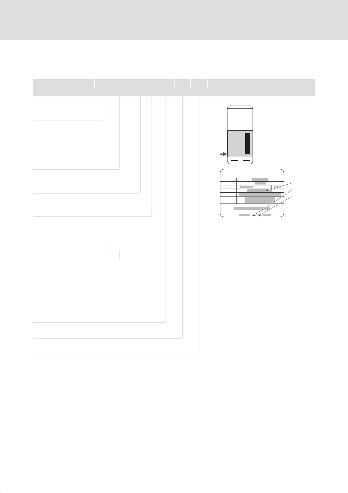
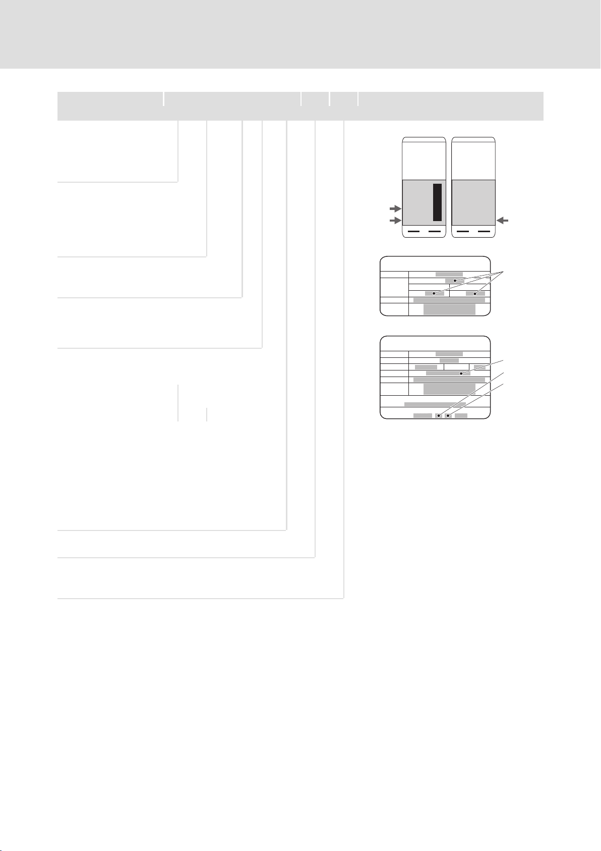
2.2.2 Parameter setting
Parameter setting
Code Meaning Value range Lenze setting
C0066 Display of the I2xt utilisation of the
C0120 Threshold: Triggering of an "OC6" error 0 ... 120 % 0 %
C0127 Threshold: Triggering of an "OC8" error 0 ... 120 % 0 %
C0128 Thermal time constant of the motor 0.1 ... 50.0 min 5.0 min
C0606 Response to "OC8" error Trip, warning, off Warning
motor
0 ... 250 % −
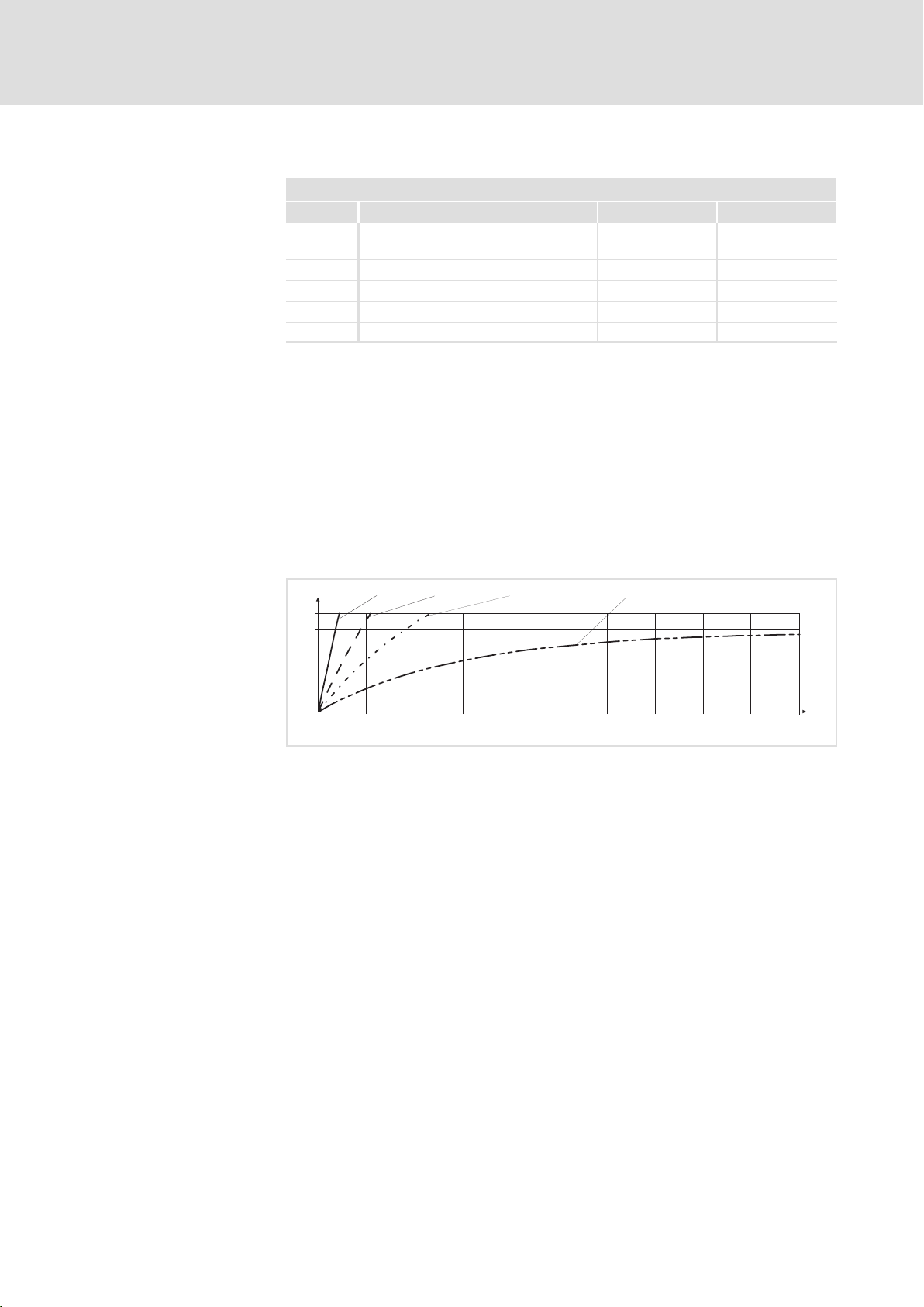
Calculating the release time
Reading the release time off
the diagram
IMActual motor current
I
Rated motor current
r
y C0120 or C0127
t +*(C0128) @ ln
ȡ
ȧ
Ȣ
1 *
ǒ
I
M
I
r
y ) 1
2
Ǔ
@ 100
ȣ
ȧ
Ȥ
ƒ The thermal capacity of the motor is expressed by the thermal motor
time factor (C0128). Please see the rated data of the motor for the
value or ask the manufacturer of the motor.
Diagram for the determination of the release times of a motor with a
thermal motor time factor of 5 min:
2
I t [%]
120
100
50
Fig. 2.2−1 I2 × t−monitoring: Release times for different motor currents and trigger
I =3×I
mot r
0
0 100 200 300 400 500 600 700 800 900
I=2×I
mot r
thresholds
Imot Motor current
I
r
2
I
tI
T Time
I =1.5×I
mot r
Rated motor current
2
t load
I =1×I
mot r
t [s]
1000
9300std105
2.2−2
EDSVF9383V EN 7.1−04/2012
Page 29

2.3 Residual hazards
Safety instructions
Residual hazards
2
2.3
Protection of persons
ƒ According to their enclosure, Lenze controllers (frequency inverters,
servo inverters, DC speed controllers) and their components can carry a
voltage, or parts of the controllers can move or rotate during operation.
Surfaces can be hot.
– If the required cover is removed, the controllers are used
inappropriately or installed or operated incorrectly, severe damage to
persons or material assets can occur.
– For more detailed information please see the documentation.
ƒ There is a high amount of energy within the controller. Therefore
always wear personal protective equipment (body protection,
headgear, eye protection, ear protection, hand guard) when working on
the controller when it is live.
ƒ Before working on the controller, check if no voltage is applied to the
power terminals.
– the power terminals U, V, W, +U
, −UG, BR1, BR2 and 101 ... 104 still
G
carry dangerous voltage for at least 5 minutes after power−off.
– the power terminals L1, L2, L3, U, V, W, +U
, −UG, BR1, BR2 and
G
101 ... 104 carry dangerous voltage when the motor is stopped.
ƒ Before power−off during DC−bus operation, all controllers must be
inhibited and disconnected from the mains.
Device protection
ƒ The discharge current to PE potential is > 3.5 mA. In accordance with
EN 61800−5−1
– a fixed installation is required.
– the design of the PE conductor has to be double or, in the case of a
single design, must have a cable cross−section of at least 10 mm
2
.
ƒ The controller can only be safely disconnected from the mains via a
contactor on the input side.
ƒ During parameter set transfer the control terminals of the controller
can have undefined states.
– Therefore the connectors X5 and X6 must be disconnected from the
controller before the transfer takes place. This ensures that the
controller is inhibited and all control terminals have the defined state
"LOW".
ƒ Frequent mains switching (e.g. inching mode via mains contactor) can
overload and destroy the input current limitation of the controller.
– Thus, at least five minutes have to pass between two switch−on
processes.
– In case of frequent, safety−related disconnections use the
"safe torque off" safety function (STO).
EDSVF9383V EN 7.1−04/2012
2.3−1
Page 30

2
2.3
Safety instructions
Residual hazards
Motor protection
ƒ For some controller settings, the connected motor may overheat (e.g.
when operating the DC injection brake or a self−ventilated motor at
low speed for longer periods).
– Using an overcurrent relay or a temperature monitoring device
provides a large degree of protection against overload.
– We recommend to use PTC thermistors or thermal contacts for motor
temperature monitoring. (Lenze three−phase AC motors are equipped
with thermal contacts (NC contacts) as standard)
– PTC thermistors or thermal contacts can be connected to the
controller.
ƒ Drives can attain dangerous overspeeds (e.g. setting of high output
frequencies with motors and machines not qualified for this purpose).
2.3−2
EDSVF9383V EN 7.1−04/2012
Page 31

3 Technical data
Contents
3.1 General data and operating conditions 3.1−1 . . . . . . . . . . . . . . . . . . . . . . . .
3.2 Weights 3.2−1 . . . . . . . . . . . . . . . . . . . . . . . . . . . . . . . . . . . . . . . . . . . . . . . . . . .
3.3 Open and closed loop control 3.3−1 . . . . . . . . . . . . . . . . . . . . . . . . . . . . . . . . .
3.4 Safety relay KSR 3.4−1 . . . . . . . . . . . . . . . . . . . . . . . . . . . . . . . . . . . . . . . . . . . . .
3.5 Rated data (devices in 400V design) 3.5−1 . . . . . . . . . . . . . . . . . . . . . . . . . . . .
3.6 Rated data (devices for 400/500V mains) 3.6−1 . . . . . . . . . . . . . . . . . . . . . . .
3.6.1 Rated data for 400 V mains voltage 3.6−1 . . . . . . . . . . . . . . . . . . . .
3.6.2 Rated data for 500 V mains voltage 3.6−2 . . . . . . . . . . . . . . . . . . . .
Technical data
Contents
3
EDSVF9383V EN 4.0−11/2007
3−1
Page 32

Page 33

General data and operating conditions
3.1 General data and operating conditions
Technical data
3
3.1
General data
Conformity and approval
Conformity
CE 2006/95/EC Low−Voltage Directive
Protection of persons and equipment
Type of protection
Earth leakage current IEC/EN 61800−5−1 > 3.5 mA Observe regulations and
Insulation of control
circuits
Insulation resistance EN 61800−5−1
Protective measures Against short circuit, earth fault (earth−fault
EMC
Noise emission EN 61800−3
Interference
immunity
EN 60529 IP20
NEMA 250 Protection against accidental contact according to
type 1
safety instructions!
IEC/EN 61800−5−1 Safe mains isolation by double (reinforced)
insulation for the terminals X1 and X5.
Basic insulation (single isolating distance) for the
terminals X3, X4, X6, X8, X9, X10 and X11.
< 2000 m site altitude: Overvoltage category III
> 2000 m site altitude: Overvoltage category II
protected during operation, limited earth−fault
protection during mains power−up), overvoltage,
motor stalling, motor overtemperature (input for
PTC or thermal contact)
Cable−guided, up to 50 m motor cable length with
RFI filter: Category C2.
Radiation, with RFI filter and installation in control
cabinet: Category C2
IEC/EN 61800−3 Category C3
EDSVF9383V EN 4.0−11/2007
3.1−1
Page 34

3
3.1
Technical data
General data and operating conditions
Operating conditions
Ambient conditions
Climatic
Storage
Transport IEC/EN 60721−3−2 2K3 (−25 ... +70 °C)
Operation
EVF9335 3K3 (0 ... +50 °C)
EVF9336 ...
EVF9338
EVF9381 ...
EVF9383
Pollution EN 61800−5−1 Degree of pollution 2
Site altitude < 4000 m amsl
Internal fan 975 m3/h volume flow
Mechanical
Vibration resistance EN 61800−5−1
Electrical
Mains connection
Power system
TT, TN
(with earthed
neutral)
DC−bus operation Possible for the variants V210, V240, V270, V300
Motor connection
Length of the
motor cable
shielded 100 m
unshielded 200 m
IEC/EN 60721−3−1
IEC/EN 60721−3−3
1K3 (−20 ... +60 °C) < 6 months
1K3 (−25 ... +40 °C) > 6 months
> 2 years: form DC bus
capacitors
3K3 (0 ... +50 °C)
> +40 °C: reduce the rated output current by
2.5 %/°C.
> 1000 m amsl: reduce the rated output current by
5 %/ 1000 m.
Operation is permitted without restrictions.
At rated mains voltage and a switching frequency
of £ 2 kHz without additional output filter.
For compliance with EMC regulations, the
permissible cable lengths may change.
3.1−2
Mounting conditions
Mounting place In the control cabinet
Mounting position Vertical
Free spaces
Dimensions
Weights
4−1
EDSVF9383V EN 4.0−11/2007
Page 35

3.2 Weights
Technical data
Weights
9300 Without RFI filter A With integrated RFI filter A
Type [kg] [kg]
EVF9335−EV 160 175
EVF9336−EV 160 175
EVF9337−EV 160 175
EVF9338−EV 200 215
EVF9381−EV 320 350
EVF9382−EV 320 350
EVF9383−EV 400 430
3
3.2
EDSVF9383V EN 4.0−11/2007
3.2−1
Page 36

Page 37

Technical data
Open and closed loop control
3.3 Open and closed loop control
Field Values
Control methods V/f characteristic control (linear, square), vector control
Switching frequency 1 kHz, 2 kHz or 4 kHz
Torque behaviour in case of vector
control
Maximum torque 1.5 × Mr for 60 s if rated motor power = rated 9300 vector power
Setting range to 1:10
(1 : 20 with feedback)
Speed control without feedback
Min. mechanical motor frequency 1 % f
r
Setting range 1 : 100 relating to fr and M
Accuracy ± 0.5 % f
N
Speed control without feedback
Min. mechanical motor frequency 0.1 % f
N
Setting range 1 : 1000 relating to fr and M
Accuracy ± 0.1 % of f
r
Output frequency
Field − 300 Hz ... + 300 Hz
Absolute resolution 0.06 Hz
Standardised resolution Parameter data: 0.01 %,
Process data: 0.006 % (= 2
14
)
Digital setpoint selection
Accuracy ± 0.005 Hz (= ± 100 ppm)
Analog setpoint selection
Linearity ± 0.15 % signal level: 5 V or 10 V
Temperature sensitivity ± 0.1 % 0 ... 50 °C
Offset ± 0.1 %
Analog inputs/outputs l 2 inputs (bipolar)
l 2 outputs (bipolar)
Digital inputs/outputs l 6 inputs (freely assignable)
l 1 input for controller inhibit
l 4 outputs freely assignable)
l 1 incremental encoder input (500 kHz, TTL level); Design: 9−pole Sub−D socket
l 1 digital frequency input (500 kHz, TTL level or 200 kHz, HTL level); type: 9−pole Sub−D
socket; can be alternatively used as incremental encoder input (200 kHz, HTL level)
l 1 master frequency output (500 kHz, TTL level); Design: 9−pole Sub−D socket
Cycle times
Digital inputs 1 ms
Digital outputs 1 ms
Analog inputs 1 ms
Analog outputs 1 ms (smoothing time: tt = 2 ms)
Operation in generator mode Integrated brake transistor (optional)
frrated motor frequency
M
rated motor torque
r
in the range of 6 ... 100 % f
Torque 0 ... M
N
in the range of 6 ... 100 % f
Torque 0 ... M
N
3
3.3
r
r
N
r
EDSVF9383V EN 4.0−11/2007
3.3−1
Page 38

Page 39

Technical data
Safety relay K
SR
3
3.4
3.4 Safety relay K
Terminal Description Field Values
X11/K32
X11/K31
X11/33
X11/34
Safety relay K
1st disconnecting path
SR
SR
Coil voltage at +20 °C DC 24 V (20 ... 30 V)
Coil resistance at +20 °C 823 W ±10 %
Rated coil power Approx. 700 mW
Max. switching voltage AC 250 V, DC 250 V (0.45 A)
Max. AC switching capacity 1500 VA
Max. switching current (ohmic load) AC 6 A (250 V), DC 6 A (50 V)
Recommended minimum load > 50 mW
Max. switching rate 6 switchings per minute
Mechanical service life 107 switching cycles
Electrical service life
at 250 V AC
(ohmic load)
at 24 V DC
(ohmic load)
105 switching cycles at 6 A
6
10
7
10
6 × 10³ switching cycles at 6 A
6
10
1.5 × 10
7
10
switching cycles at 1 A
switching cycles at 0.25 A
switching cycles at 3 A
6
switching cycles at 1 A
switching cycles at 0.1 A
EDSVF9383V EN 4.0−11/2007
3.4−1
Page 40

Page 41

Technical data
Rated data (devices in 400V design)
3.5 Rated data (devices in 400V design)
Basis of the data
Voltage Frequency
Supply
3/PE AC 400 V [UN] 340 V − 0 % ... 456 V + 0 % 45 Hz − 0 % ... 65 Hz + 0 %
DC (alternatively) [UDC] Not possible
Output voltage [U
] 3 ~ 0 ... U
OUT
N
0 ... 300 Hz
3
3.5
9300 Mains current
1)
Typical motor power
ASM (4−pole)
Type Ir [A] P
EVF9335−EV
EVF9335−EVVxxx
EVF9336−EV
EVF9336−EVVxxx
EVF9337−EV
EVF9337−EVVxxx
EVF9338−EV
EVF9338−EVVxxx
EVF9381−EV
EVF9381−EVVxxx
EVF9382−EV
EVF9382−EVVxxx
EVF9383−EV
EVF9384−EVVxxx
2)
2)
2)
2)
2)
2)
2)
200 110
238 132 200 3.3
285 160 250 4.0
356 200 300 5.0
475 250 350 6.6
570 315 450 8.0
713 400 550 10.0
The currents for EVF9381 ... EVF9383 are to be considered as total currents of master and slave
1)
For a controller switching frequency of 2 kHz
2)
Device in variant V030, V060 or V110
[kW] P
N
9300 Output currents
Rated current Maximum current
Type I
EVF9335−EV
EVF9335−EVVxxx
EVF9336−EV
EVF9336−EVVxxx
EVF9337−EV
EVF9337−EVVxxx
EVF9338−EV
EVF9338−EVVxxx
EVF9381−EV
EVF9381−EVVxxx
EVF9382−EV
EVF9382−EVVxxx
EVF9383−EV
EVF9384−EVVxxx
3)
3)
3)
3)
3)
3)
3)
1)
1 kHz
[A] I
N1
210 210 210 315 315 315
250 250 250 375 375 375
300 300 270 450 450 405
375 375 330 560 560 495
500 500 500 750 750 750
600 600 540 900 900 810
750 750 660 1125 1125 990
The currents for EVF9381 ... EVF9383 are to be considered as total currents of master and slave
Bold print = Lenze setting
1)
Switching frequency of the inverter
2)
The currents apply to a periodic load change with an overcurrent time of 1 minute at a maximum
and a base load time of 2 minutes with maximally 75 % I
3)
Device in variant V030, V060 or V110
1)
2 kHz
[A] IN4 [A] I
N2
4 kHz
1)
1 kHz
[hp] P
N
150 2.8
1)
[A] I
M1
Nx
1)
2 kHz
[A] I
M2
Power loss
[kW]
V
2)
4 kHz
M4
1)
[A]
EDSVF9383V EN 4.0−11/2007
3.5−1
Page 42

Page 43

Technical data
Rated data (devices for 400/500V mains)
Rated data for 400 V mains voltage
3.6 Rated data (devices for 400/500V mains)
Note!
Types EVF9335 ... EVF9383 for 400 V/500 V mains voltage are
suitable for DC supply or DC−bus operation together with
controllers of the 9300 series.
3.6.1 Rated data for 400 V mains voltage
Basis of the data
Voltage Frequency
Supply
3/PE AC 400 V [UN] 340 V − 0 % ... 577 V + 0 % 45 Hz − 0 % ... 65 Hz + 0 %
DC 565 V (alternatively) [UDC] DC 480 V − 0 % ... 800 V + 0 % ˘
Output voltage [U
] 3 ~ 0 ... U
OUT
N
0 ... 300 Hz
3
3.6
3.6.1
9300 Mains current
1)
Typical motor power
ASM (4−pole)
Type Ir [A] P
EVF9335−EVVxxx
EVF9336−EVVxxx
EVF9337−EVVxxx
EVF9338−EVVxxx
EVF9381−EVVxxx
EVF9382−EVVxxx
EVF9384−EVVxxx
2)
2)
2)
2)
2)
2)
2)
200 110 150 2.8
238 132 200 3.3
285 160 250 4.0
356 200 300 5.0
475 250 350 6.6
570 315 450 8.0
713 400 550 10.0
The currents for EVF9381 ... EVF9383 are to be considered as total currents of master and slave
1)
For a controller switching frequency of 2 kHz
2)
Device in variant V210, V240, V270 or V300
[kW] P
N
9300 Output currents
Rated current Maximum current
Type I
EVF9335−EVVxxx
EVF9336−EVVxxx
EVF9337−EVVxxx
EVF9338−EVVxxx
EVF9381−EVVxxx
EVF9382−EVVxxx
EVF9384−EVVxxx
3)
3)
3)
3)
3)
3)
3)
1)
1 kHz
[A] I
N1
210 210 210 315 315 315
250 250 250 375 375 375
300 300 270 450 450 405
375 375 330 560 560 495
500 500 500 750 750 750
600 600 540 900 900 810
750 750 660 1125 1125 990
The currents for EVF9381 ... EVF9383 are to be considered as total currents of master and slave
Bold print = Lenze setting
1)
Switching frequency of the inverter
2)
The currents apply to a periodic load change with an overcurrent time of 1 minute at a maximum
and a base load time of 2 minutes with maximally 75 % I
3)
Device in variant V210, V240, V270 or V300
1)
2 kHz
[A] IN4 [A] I
N2
4 kHz
1)
1 kHz
[hp] P
N
1)
[A] I
M1
Nx
2 kHz
M2
Power loss
[kW]
V
2)
1)
[A] I
4 kHz
M4
1)
[A]
EDSVF9383V EN 4.0−11/2007
3.6−1
Page 44

3
3.6
3.6.2
Technical data
Rated data (devices for 400/500V mains)
Rated data for 500 V mains voltage
3.6.2 Rated data for 500 V mains voltage
Basis of the data
Voltage Frequency
Supply
3/PE AC 500 V [UN] 340 V − 0 % ... 577 V + 0 % 45 Hz − 0 % ... 65 Hz + 0 %
DC 705 V (alternatively) [UDC] DC 480 V − 0 % ... 800 V + 0 % ˘
Output voltage [U
] 3 ~ 0 ... U
OUT
N
0 ... 300 Hz
9300 Mains current
1)
Typical motor power
ASM (4−pole)
Type Ir [A] P
EVF9335−EVVxxx
EVF9336−EVVxxx
EVF9337−EVVxxx
EVF9338−EVVxxx
EVF9381−EVVxxx
EVF9382−EVVxxx
EVF9383−EVVxxx
2)
2)
2)
2)
2)
2)
2)
200 132 200 3.0
238 160 250 3.5
285 200 300 4.3
356 250 350 5.3
475 315 450 7.0
570 400 550 8.6
713 500 ??? 700 ??? 10.6
The currents for EVF9381 ... EVF9383 are to be considered as total currents of master and slave
1)
For a controller switching frequency of 2 kHz
2)
Device in variant V210, V240, V270 or V300
[kW] P
N
9300 Output currents
Rated current Maximum current
Type I
EVF9335−EVVxxx
EVF9336−EVVxxx
EVF9337−EVVxxx
EVF9338−EVVxxx
EVF9381−EVVxxx
EVF9382−EVVxxx
EVF9384−EVVxxx
3)
3)
3)
3)
3)
3)
3)
1)
1 kHz
[A] I
N1
210 210 210 315 315 315
250 250 250 375 375 375
300 300 270 450 450 405
375 375 330 560 560 495
500 500 500 750 750 750
600 600 540 900 900 810
750 750 660 1125 1125 990
The currents for EVF9381 ... EVF9383 are to be considered as total currents of master and slave
Bold print = Lenze setting
1)
Switching frequency of the inverter
2)
The currents apply to a periodic load change with an overcurrent time of 1 minute at a maximum
and a base load time of 2 minutes with maximally 75 % I
3)
Device in variant V210, V240, V270 or V300
1)
2 kHz
[A] IN4 [A] I
N2
4 kHz
1)
1 kHz
[hp] P
N
1)
[A] I
M1
Nx
2 kHz
M2
Power loss
[kW]
V
2)
1)
[A] I
4 kHz
M4
1)
[A]
3.6−2
EDSVF9383V EN 4.0−11/2007
Page 45

Installing of the standard device
4 Installation of the standard device
4
Contents
Contents
4.1 Important notes 4.1−1 . . . . . . . . . . . . . . . . . . . . . . . . . . . . . . . . . . . . . . . . . . . .
4.2 Basic devices in the power range 110 ... 200 kW 4.2−1 . . . . . . . . . . . . . . . . . .
4.2.1 Dimensions 4.2−1 . . . . . . . . . . . . . . . . . . . . . . . . . . . . . . . . . . . . . . . .
4.2.2 Drilling the holes into the mounting plate 4.2−2 . . . . . . . . . . . . . . .
4.2.3 Fasten the mounting rails on the mounting plate 4.2−3 . . . . . . . .
4.2.4 Fasten controller on mounting plate 4.2−4 . . . . . . . . . . . . . . . . . . .
4.3 Basic devices in the power range 250 ... 400 kW 4.3−1 . . . . . . . . . . . . . . . . . .
4.3.1 Dimensions 4.3−1 . . . . . . . . . . . . . . . . . . . . . . . . . . . . . . . . . . . . . . . .
4.3.2 Drilling the holes into the mounting plate 4.3−2 . . . . . . . . . . . . . . .
4.3.3 Fasten the mounting rails on the mounting plate 4.3−3 . . . . . . . .
4.3.4 Fasten controller on mounting plate 4.3−4 . . . . . . . . . . . . . . . . . . .
EDSVF9383V EN 7.1−04/2012
4−1
Page 46

Page 47

4.1 Important notes
Installing of the standard device
Important notes
4
4.1
Transport
Mounting
ƒ Manual lifting is only permitted up to the following weight limitations:
– max. 30 kg [max. 66 lbs] for men
– max. 10 kg [max. 22 lbs] for women
– max. 5 kg [max. 11 lbs] for pregnant women
Above these limits, use appropriate hoists or conveyors! Weights of the
devices: ( 3.2−1)
ƒ For transport with hoists, observe the following basic rules:
– The payload of the hoists and load handling devices at least has to
correspond to the weight of the device. Weight of the devices:
( 3.2−1)
– Secure the device so that it cannot topple over or fall down.
– Stay out from suspended loads!
– Avoid heavy impacts during transport.
ƒ The devices are equipped with an eye bolt. The load hook can be
attached directly to the eye bolt.
ƒ Alternatively the devices can be transported with lifting straps.
– Attach the lifting straps so that the device is balanced and cannot slip
from the lifting straps.
ƒ Controller must only be used as built−in unit.
ƒ Possible mounting position: Vertically at the rear panel of the control
cabinet.
ƒ Observe free mounting spaces.
ƒ Do not exceed the permissible operating and ambient temperatures:
– Please ensure unimpeded ventilation of cooling air.
– If the cooling air contains pollutants (dust, lint, grease, aggressive
gases), which may impair the function of the controller take
measures against it, such as separate air flow, filters, regular
cleaning, etc..
EDSVF9383V EN 7.1−04/2012
4.1−1
Page 48

Page 49

Installing of the standard device
b2
d
Basic devices in the power range 110 ... 200 kW
4.2 Basic devices in the power range 110 ... 200 kW
Tip!
ƒ Lenze recommends to install an air lock. It serves to dissipate
the heated cooling air directly from the control cabinet.
– Order no. E93ZWL
ƒ A drilling jig for marking the bore holes is available as dxf−file
on the Internet in the "Download" area under www.Lenze.de.
4.2.1 Dimensions
a
a1
a2
Dimensions
c
4
4.2
4.2.1
b1
b
d
Fig. 4.2−1 Dimensions
Eyebolts
0
0
9300VEC002
EDSVF9383V EN 7.1−04/2012
Type a
[mm]a1[mm]a2[mm]b[mm]b1[mm]b2[mm]c[mm]d[mm]
EVF9335−EV
EVF9335−EVVxxx
EVF9336−EV
EVF9336−EVVxxx
EVF9337−EV
EVF9337−EVVxxx
EVF9338−EV
EVF9338−EVVxxx
500 450 225 1145 1005 15 436
9
(8×)
4.2−1
Page 50

4
4.2
4.2.2
Installing of the standard device
Basic devices in the power range 110 ... 200 kW
Drilling the holes into the mounting plate
4.2.2 Drilling the holes into the mounting plate
Assembly space Minimum clearance
Left/right of other controllers 30 mm
Left/right of a non−heat−conducting wall 100 mm
Top/bottom 200 mm
Comply with the clearances given to ensure a sufficient cooling of the
controller. When using an air lock, different clearances apply (see Mounting
Instructions for the air lock).
a1
a2
a3
b
d
a2
a1
93vec048
Fig. 4.2−2 Bore holes in the mounting plate for fixing the controller
a1 a2 a3 b d
450 mm 340 mm 225 mm 1005 mm 9 mm (12x)
1. Mark the bore holes on the mounting plate according to the figure.
2. Drill the holes into the mounting plate.
4.2−2
EDSVF9383V EN 7.1−04/2012
Page 51

Installing of the standard device
Basic devices in the power range 110 ... 200 kW
Fasten the mounting rails on the mounting plate
4.2.3 Fasten the mounting rails on the mounting plate
4
4.2
4.2.3
2
3
0
1
0
3
2
Fig. 4.2−3 Fastening the mounting rails on the mounting plate
Mounting rail
Mounting plate
Hexagon socket screw M8 × 25 mm
Spring washer M8
93vec071
1. Hold the mounting rails behind the mounting plate.
2. Fasten the mounting rails exactly at the illustrated points using 2
hexagon socket screws and spring washers on each side.
EDSVF9383V EN 7.1−04/2012
4.2−3
Page 52

4
4.2
4.2.4
Installing of the standard device
Basic devices in the power range 110 ... 200 kW
Fasten controller on mounting plate
4.2.4 Fasten controller on mounting plate
Danger!
Risk of injury due to the high weight of the controller.
The controller has to be carried using the eyebolts and an
adequate lifting tool.
0
1
3
4
4
3
2
9300vec070
Fig. 4.2−4 Fastening the controller on mounting plate
Eye bolts 8 hexagon socket screws M8 × 25 mm
Controller 8 spring washers M8
Mounting plate
1. Put the controller on the mounting plate.
2. Fasten the controller exactly at the illustrated points using 5 hexagon
socket screws and spring washers at the top and 3 hexagon socket
screws and spring washers at the bottom.
4.2−4
EDSVF9383V EN 7.1−04/2012
Page 53

Installing of the standard device
b2
d
Basic devices in the power range 250 ... 400 kW
4.3 Basic devices in the power range 250 ... 400 kW
Tip!
ƒ Lenze recommends to install an air lock. The air lock serves to
dissipate the heated cooling air directly from the control
cabinet.
– Order no. E93ZWL2
ƒ A drilling jig for marking the bore holes is available as dxf−file
in the Internet in the "Download" area under www.Lenze.de.
4.3.1 Dimensions
a
a1
a2
a3
Dimensions
c
4
4.3
4.3.1
0
0
0
b1
b
d
9300VEC039
Fig. 4.3−1 Dimensions
Eyebolts
EDSVF9383V EN 7.1−04/2012
Type a
[mm]a1[mm]a2[mm]a3[mm]b[mm]b1[mm]b2[mm]c[mm]d[mm]
EVF9381−EV
EVF9381−EVVxxx
EVF9382−EV
EVF9382−EVVxxx
EVF9383−EV
EVF9383−EVVxxx
1050 450 225 50 1145 1005 15 436
9
(16×)
4.3−1
Page 54

4
4.3
4.3.2
Installing of the standard device
Basic devices in the power range 250 ... 400 kW
Drilling the holes into the mounting plate
4.3.2 Drilling the holes into the mounting plate
Assembly space Minimum clearance
Left/right of other controllers 30 mm
Left/right of a non−heat−conducting wall 100 mm
Top/bottom 200 mm
Comply with the clearances given to ensure a sufficient cooling of the
controller. When using an air lock, different clearances apply (see Mounting
Instructions for the air lock).
a
a1 a1
a2 a2
a3
a3
b
d
a2 a2
a1 a1
93vec079
Fig. 4.3−2 Bore holes in the mounting plate for fixing the controller
a a1 a2 a3 b d
550 mm 450 mm 340 mm 225 mm 1005 mm 9 mm (24x)
1. Mark the bore holes on the mounting plate according to the figure.
2. Drill the holes into the mounting plate.
4.3−2
EDSVF9383V EN 7.1−04/2012
Page 55

Installing of the standard device
Basic devices in the power range 250 ... 400 kW
Fasten the mounting rails on the mounting plate
4.3.3 Fasten the mounting rails on the mounting plate
4
4.3
4.3.3
0
22
33
1
0
33
22
Fig. 4.3−3 Fastening the mounting rails on the mounting plate
Mounting rail
Mounting plate
Hexagon socket screw M8 × 25 mm
Spring washer M8
9300vec080
1. Hold the mounting rails behind the mounting plate.
2. Fasten the mounting rails exactly at the illustrated points using 2
hexagon socket screws and spring washers on each side.
EDSVF9383V EN 7.1−04/2012
4.3−3
Page 56

4
4.3
4.3.4
Installing of the standard device
Basic devices in the power range 250 ... 400 kW
Fasten controller on mounting plate
4.3.4 Fasten controller on mounting plate
Danger!
Risk of injury due to the high weight of the controller.
The controller has to be carried using the eyebolts and an
adequate lifting tool.
00
12
4
5
3
5
4
9300vec081
Fig. 4.3−4 Fastening the controller on mounting plate
Eyebolts Mounting plate
Master 16 hexagon socket screws M8 × 25 mm
Slave 16 spring washers M8
1. Put master and slave on the mounting plate.
2. Fasten the master and slave each with five hexagon socket screws and
spring washers at the top and 3 hexagon socket screws and spring
washers at the bottom exactly at the marked point.
4.3−4
EDSVF9383V EN 7.1−04/2012
Page 57

Wiring of the standard device
5 Wiring of the standard device
Contents
5.1 Important notes 5.1−1 . . . . . . . . . . . . . . . . . . . . . . . . . . . . . . . . . . . . . . . . . . . .
5.1.1 Protection of persons 5.1−1 . . . . . . . . . . . . . . . . . . . . . . . . . . . . . . . .
5.1.2 Device protection 5.1−3 . . . . . . . . . . . . . . . . . . . . . . . . . . . . . . . . . . .
5.1.3 Motor protection 5.1−3 . . . . . . . . . . . . . . . . . . . . . . . . . . . . . . . . . . . .
5.2 Notes on project planning 5.2−1 . . . . . . . . . . . . . . . . . . . . . . . . . . . . . . . . . . . .
5.2.1 Supply forms / electrical supply conditions 5.2−1 . . . . . . . . . . . . . .
5.2.2 Operation on public supply systems
(compliance with EN 61000−3−2) 5.2−1 . . . . . . . . . . . . . . . . . . . . . . .
5.2.3 Operation at earth−leakage circuit breaker (e.l.c.b.) 5.2−2 . . . . . . .
5.2.4 Interaction with compensation equipment 5.2−2 . . . . . . . . . . . . . .
5.2.5 Discharge current for mobile systems 5.2−3 . . . . . . . . . . . . . . . . . .
5.2.6 Dimensioning of mains and motor cables 5.2−4 . . . . . . . . . . . . . . .
5
Contents
5.3 Basics for wiring according to EMC 5.3−1 . . . . . . . . . . . . . . . . . . . . . . . . . . . .
5.3.1 Shielding 5.3−1 . . . . . . . . . . . . . . . . . . . . . . . . . . . . . . . . . . . . . . . . . . .
5.3.2 Mains connection, DC supply 5.3−1 . . . . . . . . . . . . . . . . . . . . . . . . . .
5.3.3 Motor cable 5.3−2 . . . . . . . . . . . . . . . . . . . . . . . . . . . . . . . . . . . . . . . .
5.3.4 Control cables 5.3−3 . . . . . . . . . . . . . . . . . . . . . . . . . . . . . . . . . . . . . .
5.3.5 Installation in the control cabinet 5.3−4 . . . . . . . . . . . . . . . . . . . . . .
5.3.6 Wiring outside of the control cabinet 5.3−5 . . . . . . . . . . . . . . . . . . .
5.3.7 Detecting and eliminating EMC interferences 5.3−6 . . . . . . . . . . . .
5.4 Basic devices in the power range 110 ... 200 kW 5.4−1 . . . . . . . . . . . . . . . . . .
5.4.1 Wiring according to EMC (CE−typical drive system) 5.4−1 . . . . . . . .
5.4.2 Mains connection 400 V devices 5.4−3 . . . . . . . . . . . . . . . . . . . . . . .
5.4.3 Mains connection 400/500 V devices 5.4−3 . . . . . . . . . . . . . . . . . . .
5.4.4 DC supply 400/500 V devices 5.4−4 . . . . . . . . . . . . . . . . . . . . . . . . . .
5.4.5 Fan connection 400/500 V devices 5.4−4 . . . . . . . . . . . . . . . . . . . . .
5.4.6 Fuses and cable cross−sections 5.4−6 . . . . . . . . . . . . . . . . . . . . . . . . .
5.4.7 Motor connection 5.4−7 . . . . . . . . . . . . . . . . . . . . . . . . . . . . . . . . . . .
5.4.8 Wiring of motor temperature monitoring 5.4−8 . . . . . . . . . . . . . . .
EDSVF9383V EN 7.1−04/2012
5−1
Page 58

5
Wiring of the standard device
Contents
5.5 Basic devices in the power range 250 ... 400 kW 5.5−1 . . . . . . . . . . . . . . . . . .
5.5.1 Wiring according to EMC (CE−typical drive system) 5.5−1 . . . . . . . .
5.5.2 Master and slave connection 5.5−3 . . . . . . . . . . . . . . . . . . . . . . . . . .
5.5.3 Mains connection 400 V devices 5.5−7 . . . . . . . . . . . . . . . . . . . . . . .
5.5.4 Mains connection 400/500 V devices 5.5−7 . . . . . . . . . . . . . . . . . . .
5.5.5 DC supply 400/500 V devices 5.5−8 . . . . . . . . . . . . . . . . . . . . . . . . . .
5.5.6 Fan connection 400/500 V devices 5.5−8 . . . . . . . . . . . . . . . . . . . . .
5.5.7 Fuses and cable cross−sections 5.5−10 . . . . . . . . . . . . . . . . . . . . . . . . .
5.5.8 Motor connection 5.5−11 . . . . . . . . . . . . . . . . . . . . . . . . . . . . . . . . . . .
5.5.9 Wiring of motor temperature monitoring 5.5−13 . . . . . . . . . . . . . . .
5.6 Control terminals 5.6−1 . . . . . . . . . . . . . . . . . . . . . . . . . . . . . . . . . . . . . . . . . . .
5.6.1 Important notes 5.6−1 . . . . . . . . . . . . . . . . . . . . . . . . . . . . . . . . . . . . .
5.6.2 Connection terminal of the control card 5.6−3 . . . . . . . . . . . . . . . . .
5.6.3 With function "Safe torque off" active 5.6−4 . . . . . . . . . . . . . . . . . .
5.6.4 With function "Safe torque off" deactivated 5.6−7 . . . . . . . . . . . . .
5.6.5 Terminal assignment 5.6−9 . . . . . . . . . . . . . . . . . . . . . . . . . . . . . . . .
5.7 Wiring of the system bus (CAN) 5.7−1 . . . . . . . . . . . . . . . . . . . . . . . . . . . . . . .
5.8 Wiring of the feedback system 5.8−1 . . . . . . . . . . . . . . . . . . . . . . . . . . . . . . . .
5.8.1 Important notes 5.8−1 . . . . . . . . . . . . . . . . . . . . . . . . . . . . . . . . . . . . .
5.8.2 Incremental encoder with TTL level at X8 5.8−2 . . . . . . . . . . . . . . . .
5.8.3 Incremental encoder with HTL level at X9 5.8−3 . . . . . . . . . . . . . . .
5.9 Wiring of digital frequency input / digital frequency output 5.9−1 . . . . . .
5.10 Communication modules 5.10−1 . . . . . . . . . . . . . . . . . . . . . . . . . . . . . . . . . . . .
5−2
EDSVF9383V EN 7.1−04/2012
Page 59

5.1 Important notes
Stop!
5.1.1 Protection of persons
Danger!
Important notes
Protection of persons
The drive controller contains electrostatically sensitive
components.
The personnel must be free of electrostatic charge when carrying
out assembly and service operations.
Before working on the controller, check that no voltage is applied
to the power terminals:
ƒ The power terminals U, V, W, +U
101 ... 104 remain live for at least five minutes after
disconnecting the mains.
ƒ The power terminals L1, L2, L3, U, V, W, +U
101 ... 104 remain live when the motor is stopped.
, −UG, BR1, BR2 and
G
, −UG, BR1, BR2 and
G
5.1
5.1.1
Pluggable terminal strips
All pluggable terminals must only be connected or disconnected when no
voltage is applied!
EDSVF9383V EN 7.1−04/2012
5.1−1
Page 60

5.1
5.1.1
Important notes
Protection of persons
Electrical isolation
The terminals X1 and X5 have a double (reinforced) insulation in accordance
with EN 61800−5−1. The protection against accidental contact is ensured
without any further measures.
Danger!
ƒ Terminals X3, X4, X6, X8, X9, X10, X11 have a single basic
insulation (single isolating distance).
ƒ Protection against accidental contact in case of a defective
isolating distance is only guaranteed through external
measures, e.g. double insulation.
ƒ If an external DC 24 V voltage source is used, the insulation
level of the controller depends on the insulation level of the
voltage source.
L1
24 VDC
N
39
101
102
103
104
L1
L2
L3
PE
+U
-U
BR1
BR2
PE
U
V
W
59
G
G
X3
X6 X8 X9 X10
X4
Fig. 5.1−1 Electrical isolation between power terminals, control terminals and housing
E1…E5, ST1, ST2
A1…A4
X11
Double (reinforced) insulation
Basic insulation
28
X5
X1
9300VEC009
Replacing defective fuses
Disconnecting the controller
from the mains
5.1−2
Only replace defective fuses in the deenergised state to the type specified.
Only carry out the safety−related disconnection of the controller from the
mains via a contactor on the input side or a manually operated toggle switch.
EDSVF9383V EN 7.1−04/2012
Page 61

5.1.2 Device protection
ƒ In the event of condensation, connect the controller to the mains
ƒ The controller is protected by external fuses.
ƒ Length of the screws for connecting the shield sheet for the control
ƒ Cyclic connection and disconnection of the supply voltage can overload
ƒ Switching on the motor side of the controller is only permitted for
ƒ Provide unused control inputs and outputs with terminal strips. Cover
Important notes
Device protection
voltage only after the humidity has evaporated.
cables: 12 mm.
and destroy the input current limitation of the controller. In case of
cyclic mains switching over a longer period of time, the controller must
not be switched on more frequently than every 5 minutes!
emergency switch−off.
unused Sub−D sockets with protective covers included in the scope of
supply.
5.1
5.1.2
5.1.3 Motor protection
ƒ Extensive protection against overload:
ƒ Only use motors with an insulation suitable for the inverter operation:
Note!
– By overcurrent relays or temperature monitoring.
– We recommend the use of PTC thermistors or thermostats to monitor
the motor temperature.
– PTC thermistors or thermostats can be connected to the controller.
– For monitoring the motor, we recommend the use of the I
monitoring.
– Insulation resistance: min. û = 1.5 kV, min. du/dt = 5 kV/ms
– When using motors with an unknown insulation resistance, please
contact your motor supplier.
To avoid bearing currents, Lenze recommends to use motors
with insulated non−drive end bearings. Optionally, motor chokes
can be used to reduce bearing currents.
2
xt
EDSVF9383V EN 7.1−04/2012
5.1−3
Page 62

Page 63

Notes on project planning
Supply forms / electrical supply conditions
5.2 Notes on project planning
5.2.1 Supply forms / electrical supply conditions
Please observe the restrictions of each mains type!
Mains Controller operation Notes
With insulated
neutral point
(TT/TN systems)
With insulated
neutral point
(IT systems)
DC−supply via
/−U
+U
G
G
No restrictions
Not permitted. ˙
Permitted if the DC voltage is
symmetrical to PE
Comply with controller ratings.
l Effective mains current: See
chapter "Technical data"
The controller will be destroyed
when grounding +U
−U
conductor.
G
5.2.2 Operation on public supply systems (compliance with EN 61000−3−2)
conductor or
G
5.2
5.2.1
Measures for compliance with
the standard
European standard EN 61000−3−2 defines limit values for the limitation of
harmonic currents in the supply system. Non−linear consumers (e.g.
frequency inverters) generate harmonic currents which "pollute" the
supplying mains and may therefore interfere with other consumers. The
standard aims at assuring the quality of public supply systems and reducing
the mains load.
Note!
The standard only applies to public systems. Mains which are
provided with a transformer substation of their own as in
industrial plants are not public and not included in the
application range of the standard.
If a device or machine consists of several components, the limit
values of the standard apply to the entire unit.
With the measures described, the controllers comply with the limit values
according to EN 61000−3−2.
Operation on public
supply systems
1)
The additional measures mentioned have the effect that solely the controllers meet the
requirements of EN 61000−3−2. The machine/system manufacturer is responsible for the
compliance with the requirements for the machine/system!
EN 61000−3−2 Limitation of harmonic currents
Total power on the
mains
< 1 kW With mains choke
> 1 kW No measures required
Compliance with the requirements
1)
EDSVF9383V EN 7.1−04/2012
5.2−1
Page 64

5.2
5.2.3
5.2.3 Operation at earth−leakage circuit breaker (e.l.c.b.)
Notes on project planning
Operation at earth−leakage circuit breaker (e.l.c.b.)
Danger!
The controllers are internally fitted with a mains rectifier. In case
of a short circuit to frame a pulsating DC residual current can
prevent the AC sensitive or pulse current sensitive earth−leakage
circuit breakers from being activated, thus cancelling the
protective function for the entire equipment being operated on
this earth−leakage circuit breaker.
ƒ For the protection of persons and farm animals (DIN VDE 0100), we
recommend
– pulse current sensitive earth−leakage circuit breakers for plants
including controllers with a single−phase mains connection (L1/N).
– universal−current sensitive earth−leakage circuit breakers for plants
including controllers with a three−phase mains connection (L1/L2/L3).
ƒ Only install the earth−leakage circuit breaker between supplying mains
and drive controller.
ƒ Earth−leakage circuit breakers may trigger a false alarm due to
– capacitive compensation currents flowing in the cable shields during
operation (particularly with long, shielded motor cables),
– simultaneous connection of several inverters to the mains
– the use of additional interference filters.
5.2.4 Interaction with compensation equipment
ƒ Controllers only consume very little reactive power of the fundamental
wave from the AC supply mains. Therefore, a compensation is not
required.
ƒ If the controllers are connected to a supply system with compensation
equipment, this equipment must comprise chokes.
– For this, contact the supplier of the compensation equipment.
5.2−2
EDSVF9383V EN 7.1−04/2012
Page 65

5.2.5 Discharge current for mobile systems
Frequency inverters with internal or external RFI filters usually have a
discharge current to PE potential that is higher than 3.5 mA AC or 10 mA DC.
Therefore, fixed installation as protection is required (see EN 61800−5−1).
This must be indicated in the operational documents.
If a fixed installation is not possible for a mobile consumer although the
discharge current to PE potential is higher than 3.5 mA AC or 10 mA DC, an
additional two−winding transformer (isolating transformer) can be included
in the current supply as a suitable countermeasure. Here, the PE conductor
is connected to the PEs of the drive (filter, inverter, motor, shieldings) and
also to one of the poles of the secondary winding of the isolating
transformer.
Devices with a three−phase supply must have a corresponding isolating
transformer with a secondary star connection, the star point being
connected to the PE conductor.
Notes on project planning
Discharge current for mobile systems
5.2
5.2.5
filter inverter
L1
prim.
N
PE
Fig. 5.2−1 Installation of a two−winding transformer (isolating transformer)
sec.
L1L1 LL2
U
V
W
N1 NN2
M
3~
8200vec017
EDSVF9383V EN 7.1−04/2012
5.2−3
Page 66

5.2
5.2.6
5.2.6 Dimensioning of mains and motor cables
Notes on project planning
Dimensioning of mains and motor cables
Danger!
Observe all national and regional regulations for the cables.
You can use single and multi−core cables. If a cable consists of several cores
per phase, it can be necessary to connect the controller by means of common
cable glands.
Maximum cable cross−section for power connections (screw terminals):
9300 vector Maximum cable cross−section
L1, L2, L3
U, V, W, BR1, BR2
Type [mm2] [mm2] [mm2]
EVF9335−EV
EVF9335−EVxxx
EVF9336−EV
EVF9336−EVxxx
EVF9337−EV
EVF9337−EVxxx
EVF9338−EV
EVF9338−EVxxx
Master Slave Master Slave Master Slave
EVF9381−EV
EVF9381−EVxxx
EVF9382−EV
EVF9382−EVxxx
EVF9383−EV
EVF9383−EVxxx
1)
Two conductors per path; both conductors must have the same cross−section
(2 × 50)
(2 × 50)
(2 × 95)
150
150
240
150
(2 × 50)
150
(2 × 50)
150
(2 × 50)
240
(2 × 95)
1)
1)
1)
1)
1)
1)
1)
150
(2 × 50)
150
(2 × 50)
240
(2 × 95)
1)
1)
1)
150
(2 × 50)
240
(2 × 95)
240
(2 × 95)
+UG, −U
150
(2 × 50)
150
(2 × 50)
240
(2 × 95)
240
(2 × 95)
1)
1)
1)
G
1)
1)
1)
1)
150
(2 × 50)
240
(2 × 95)
240
(2 × 95)
1)
1)
1)
PE
95
95
95
150
95 95
95 95
150 150
Mains cable, DC cable
Motor cable
The effectively required cable cross−section depends e.g. on the application
and environmental conditions and the cable type used. It is not required that
mains and motor cable have the same cable cross−section.
It is not necessary to shield the mains cable. In DC−bus operation or with DC
supply we recommend shielded cables.
It is not necessary to fuse the motor cable. For EMC reasons we recommend
shielded motor cables. You can use common metal clamps to connect the
shield.
5.2−4
EDSVF9383V EN 7.1−04/2012
Page 67

5.3 Basics for wiring according to EMC
5.3.1 Shielding
The shielding quality is determined by a good shield connection:
ƒ Connect the shield with a surface as large as possible.
ƒ Use a conductive clamp to connect the shield to the conductive and
grounded mounting plate with a surface as large as possible.
ƒ Unshielded cable ends must always be as short as possible.
5.3.2 Mains connection, DC supply
ƒ You can use unshielded single cores or unshielded cables to connect
the controller and the mains choke to the mains.
ƒ For DC−bus operation or DC supply, use shielded cables.
Basics for wiring according to EMC
Shielding
5.3
5.3.1
ƒ The cable cross−section must be dimensioned for the assigned fuse
protection (national and regional regulations).
EDSVF9383V EN 7.1−04/2012
5.3−1
Page 68

5.3
5.3.3
5.3.3 Motor cable
Basics for wiring according to EMC
Motor cable
ƒ Use only shielded motor cables with braid made of tinned or
nickel−plated copper. Shields made of steel braid are not suitable.
– The overlap rate of the braid must be at least 70 % with an overlap
angle of 90 °.
ƒ The cables used must meet the requirements of the application (e.g.
EN 60204−1).
ƒ The cable for the motor temperature monitoring (PTC or thermal
contact) must be shielded and separated from the motor cable.
– With Lenze system cables, the cable for the motor temperature
monitoring is integrated into the motor cable.
ƒ Always place the shield of the motor cable at both sides − at the drive
controller and at the motor.
– Always connect the shields to the conductive and grounded
mounting plate with a surface as large as possible.
ƒ The motor cable is perfectly installed if
– it is routed separately of mains cables and control cables,
– crosses mains cables and control cables only at a right angle,
– is not interrupted.
ƒ If it is inevitable to have an interruption (e.g. through chokes,
contactors or terminals):
– The unshielded cable must not be longer than 100 mm (depending
on the cable cross−section).
– Chokes, contactors, terminals, etc. must be separated from other
components (min. distance = 100 mm).
– The motor cable shield must be connected to the mounting plate
with a surface as large as possible directly before and after the point
of interruption.
ƒ Connect the shield in the motor terminal box or at the motor housing
to PE with a surface as large as possible.
– Metal cable glands at the motor terminal box ensure that the shield
is connected to the motor housing with a surface as large as possible.
5.3−2
EDSVF9383V EN 7.1−04/2012
Page 69

5.3.4 Control cables
Basics for wiring according to EMC
Control cables
ƒ Control cables must be shielded to minimise interference injections.
ƒ For lengths of 200 mm and more, use only shielded cables for analog
and digital inputs and outputs. Under 200 mm, unshielded but twisted
cables may be used.
ƒ Connect the shield correctly:
– The shield connections of the control cables must be at a distance of
at least 50 mm from the shield connections of the motor cables and
DC cables.
– Connect the shield of digital input and output cables at both ends.
– Connect the shield of analog input and output cables at one end (at
the drive controller).
ƒ To achieve an optimum shielding effect (in case of very long cables,
with high interference) one shield end of analog input and output
cables can be connected to PE potential via a capacitor (e.g.
10 nF/250 V) (see sketch).
5.3.4
5.3
Fig. 5.3−1 Shielding of long, analog control cables
9300vec043
EDSVF9383V EN 7.1−04/2012
5.3−3
Page 70

5.3
5.3.5
Basics for wiring according to EMC
Installation in the control cabinet
5.3.5 Installation in the control cabinet
Mounting plate requirements
ƒ Only use mounting plates with conductive surfaces (zinc−coated or
V2A−steel).
ƒ Painted mounting plates are not suitable even if the paint is removed
from the contact surfaces.
ƒ If several mounting plates are used, ensure a large−surface connection
between the mounting plates (e.g. by using earthing strips).
Mounting of the components
ƒ Connect the controller and the chokes to the grounded mounting plate
with a surface as large as possible.
Optimum cable routing
ƒ The motor cable is optimally installed if
– it is separated from mains cables and control cables,
– it crosses mains cables and control cables at right angles.
ƒ Always install cables close to the mounting plate (reference potential),
as freely suspended cables act like aerials.
ƒ Lead the cables to the terminals in a straight line (avoid tangles of
cables).
Earth connections
ƒ Use separated cable channels for motor cables and control cables. Do
not mix up different cable types in one cable channel.
ƒ Minimise coupling capacities and coupling inductances by avoiding
unnecessary cable lengths and reserve loops.
ƒ Short−circuit unused cores to the reference potential.
ƒ Install the positive and negative wires for DC 24 V close to each other
over the entire length to avoid loops.
ƒ Connect all components (controller, chokes) to a central earthing point
(PE rail).
ƒ Set up a star−shape earthing system.
ƒ Comply with the corresponding minimum cable cross−sections.
5.3−4
EDSVF9383V EN 7.1−04/2012
Page 71

5.3.6 Wiring outside of the control cabinet
Notes for cable routing outside the control cabinet:
ƒ The longer the cables the greater the space between the cables must
be.
ƒ If cables for different signal types are routed in parallel, the
interferences can be minimized by means of a metal barrier or
separated cable ducts.
Cover
Basics for wiring according to EMC
Wiring outside of the control cabinet
Barrierwithout
opening
5.3
5.3.6
Signal cables
Fig. 5.3−2 Cable routing in the cable duct with barrier
Cable duct
Fig. 5.3−3 Cable routing in separated cable ducts
Power cables
Cover
Communicationcables
Measuring cables
Analog cables
Control cables
Power cables
EMVallg001
EMVallg002
EDSVF9383V EN 7.1−04/2012
5.3−5
Page 72

5.3
5.3.7
5.3.7 Detecting and eliminating EMC interferences
Basics for wiring according to EMC
Detecting and eliminating EMC interferences
Fault Cause Remedy
Interferences of
analog setpoints of
your own or other
devices and
measuring systems
Conducted
interference level is
exceeded on the
supply side
Unshielded motor cable
Shield contact is not extensive
enough
Shield of the motor cable is
interrupted by terminal strips,
switched, etc.
Install additional unshielded
cables inside the motor cable (e.g.
for motor temperature
monitoring)
Too long and unshielded cable
ends of the motor cable
Terminal strips for the motor
cable are directly located next to
the mains terminals
Mounting plate varnished Optimise PE connection:
HF short circuit Check cable routing
Use shielded motor cable
Carry out optimal shielding as
specified
l Separate components from
other component part with a
minimum distance of 100 mm
l Use motor choke/motor filter
Install and shield additional cables
separately
Shorten unshielded cable ends to
maximally 40 mm
Spatially separate the terminal
strips for the motor cable from
main terminals and other control
terminals with a minimum
distance of 100 mm
l Remove varnish
l Use zinc−coated mounting
plate
5.3−6
EDSVF9383V EN 7.1−04/2012
Page 73

Basic devices in the power range 110 ... 200 kW
Wiring according to EMC (CE−typical drive system)
5.4 Basic devices in the power range 110 ... 200 kW
5.4.1 Wiring according to EMC (CE−typical drive system)
The drives comply with the EC Directive on "Electromagnetic Compatibility"
if they are installed in accordance with the specifications for the CE−typical
drive system. The user is responsible for the compliance of the machine
application with the EC Directive.
Note!
Observe the notes given in the chapter "Basics for wiring
according to EMC"!
5.4
5.4.1
EDSVF9383V EN 7.1−04/2012
5.4−1
Page 74

5.4
5.4.1
L1
L2
L3
N
PE
Basic devices in the power range 110 ... 200 kW
Wiring according to EMC (CE−typical drive system)
F1…F3
K10
33
34
X5
28
E1
E2
E3
E4
E5
39
A1
A2
A3
A4
59
T1 T2
101 102 103 104
EVF9335-EV …
EVF9338-EV
PEUVW
PES
+
DC 24 V
–
PES
PES PES
X11
K31
K32
ST1
ST2
PESPES
IN1
Z1
IN2
IN3
IN4
PE
PE
BR1BR2
L1 L2
+UG -UG
L3
PES
X6
63
7
62
7
4
3
2
1
PES
S2
S1
K10
K10
PE
PES
PES
PES
X8/8
X8/5
PES
KTY
J>
PE
M
3~
M
PE
3~
PES PES
PES PES
PE
PES
RB2
RB1PE
RB
JRB
T2T1
Z2
9300VEC007
Fig. 5.4−1 Example for wiring in accordance with EMC regulations
F1 ... F3 Fuses
K10 Mains contactor
Z1 Programmable logic controller (PLC)
Z2 Brake resistor
S1 Mains contactor on
S2 Mains contactor off
+U
, −U
G
G
DC−bus connection
PES HF shield termination through large−surface connection to PE
5.4−2
EDSVF9383V EN 7.1−04/2012
Page 75

Basic devices in the power range 110 ... 200 kW
5.4.2 Mains connection 400 V devices
Stop!
The user is responsible for sufficient strain relief!
Mains connection 400 V devices
5.4
5.4.2
PE
M8
25-30 Nm
L1, L2,
L3
221-264 lb-in
PE
M6
15-20 Nm
133-176 lb-in
Fig. 5.4−2 Mains connection example
BR1, BR2 Brake resistors can only be operated with variants V060 and
5.4.3 Mains connection 400/500 V devices
Stop!
The user is responsible for sufficient strain relief!
BR1
V110
BR2
40 mm
UVWL1 L2 L3
PE
9300VEC003
EDSVF9383V EN 7.1−04/2012
PE
L3
L2
101
102
103
104
M8
25-30 Nm
L1, L2,
L3
221-264 lb-in
PE
M6
15-20 Nm
133-176 lb-in
Fig. 5.4−3 Mains connection example
BR1, BR2 Brake resistors can only be operated with variants V270 and
V300
BR2BR1+UG -UG
40 mm
PE
U
VWL1
9300VEC032
5.4−3
Page 76

5.4
5.4.4
5.4.4 DC supply 400/500 V devices
Basic devices in the power range 110 ... 200 kW
DC supply 400/500 V devices
Stop!
The user is responsible for sufficient strain relief!
ƒ For compliance with EMC requirements, Lenze recommends to use
shielded DC−bus cables.
ƒ Shield clamps are not included in the scope of supply.
L2
101
102
103
104
0
M6
15-20 Nm
PE
133-176 lb-in
40 mm
Fig. 5.4−4 Connection example to +UG and −U
BR1, BR2 Brake resistors can only be operated with variants V270 and V300
Connect the DC−bus cable shield to the conductive control cabinet
Conductive surface
Ensure to have the poles right!
5.4.5 Fan connection 400/500 V devices
Fan connection when
controller is supplied with
mains voltage
Lay a bridge between the terminals when a controller is operated on a mains.
AC 340 ... 440 V AC 440 ... 577 V
PE
L3
+U
G
-U
G
BR2BR1+UG -UG
M8
25-30 Nm
221-264 lb-in
max.
300 mm
1
G
PE
U
VWL1
9300VEC074
mounting plate with a contact surface as large as possible by using
the shield clamps.
(when being delivered)
5.4−4
101
102
103
104
L1 L2
L1 L2
101
102
103
104
9300vec044 9300vec045
EDSVF9383V EN 7.1−04/2012
Page 77

Fan connection when
controller is supplied via the
DC bus
Basic devices in the power range 110 ... 200 kW
Fan connection 400/500 V devices
5.4
5.4.5
Danger!
When the fan is externally supplied with voltage, the terminal L2
carries dangerous mains voltage!
When the controller is supplied via the DC bus, the fan must be separately
supplied with mains voltage (see ). In this case, the bridge between the
terminals 102 and 103 must be removed (see ).
Exchange defect fuse
Remove bridge
0
101
102
103
L1 L2
104
Mains connection for the operation of the fan on
AC 340 ... 440 V AC 440 ... 577 V
1
L1 L2
101
102
103
104
1
L1 L2
101
102
103
104
}
9300vec160 9300vec046 9300vec047
AC 340 … 440 V
In case of an external voltage supply the fan is protected by a fuse integrated
in terminal 104.
0
1
L1 L2
101
102
103
104
AC 440 … 577 V
Fig. 5.4−5 Fusing of the fan
Open the fuse holder.
Remove the defect fuse from the support and replace it by the following
type:
Type: 500V SA 2A 6.32
Ref. no.: P098131
Manufacturer: Ferraz Shawmut
9300vec161
EDSVF9383V EN 7.1−04/2012
5.4−5
Page 78

5.4
5.4.6
5.4.6 Fuses and cable cross−sections
Basic devices in the power range 110 ... 200 kW
Fuses and cable cross−sections
Installation in accordance
with EN 60204−1
Fuses and cable cross−sections
for the mains connection
Supply conditions
Range Description
Fuses l Utilisation category: only gG/gL or gRL
Cables Laying systems B2 and C: Use of PVC−insulated copper cables, conductor
RCCB l Controllers can cause a DC current in the PE conductor. If a residual current
Observe all national and regional regulations!
9300 Fuse Cable cross−section FI
Type [A] [mm2] [mm2] [mA]
EVF9335−EVV
EVF9335−EVVxxx
EVF9336−EVV
EVF9336−EVxxx
EVF9337−EVV
EVF9337−EVVxxx
EVF9338−EVV
EVF9338−EVVxxx
1)
Two conductors per path; both conductors must have the same cross−section
2)
Universal current−sensitive earth−leakage circuit breaker
temperature < 70 °C, ambient temperature < 40 °C, no bundling of the cables or
cores, three loaded cores. The data are recommendations. Other
dimensionings/laying systems are possible (e.g. in accordance with VDE 0298−4).
device (RCD) or a fault current monitoring unit (RCM) is used for protection in
the case of direct or indirect contact, only one RCD/RCM of the following type
can be used on the current supply side:
– Type B (universal−current sensitive) for connection to a three−phase system
– Type A (pulse−current sensitive) or type B (universal−current sensitive) for
connection to a 1−phase system
Alternatively another protective measure can be used, like for instance
isolation from the environment by means of double or reinforced insulation,
or isolation from the supply system by using a transformer.
l Earth−leakage circuit breakers must only be installed between mains supply
and controller.
Rated fuse current Laying system F
L1, L2, L3 PE
250
315
315
400
150
2 × 50
150
2 × 50
150
2 × 50
240
2 × 95
1)
1)
1)
1)
95 300
95 300
95 300
150 300
1)
Fuses and cable cross−sections
for DC−bus connection
5.4−6
9300 Fuse Cable cross−section
Quantity Rated fuse current Laying system F
+UG, −U
G
Type [A] [mm2] [mm2]
EVF9335−EVV2xx
EVF9335−EVV300
EVF9336−EVV2xx
EVF9336−EVV300
EVF9337−EVV2xx
EVF9337−EVV300
EVF9338−EVV2xx
EVF9338−EVV300
1)
Two conductors per path; both conductors must have the same cross−section
1
1 400 2 × 50
2 350 2 × 95
2 400 2 × 95
400 2 × 50
EDSVF9383V EN 7.1−04/2012
1)
1)
1)
1)
PE
95
95
95
150
Page 79

5.4.7 Motor connection
ƒ To comply with the EMC regulations, Lenze recommends to use
ƒ Shield clamps are not included in the scope of supply.
Stop!
Basic devices in the power range 110 ... 200 kW
Motor connection
shielded motor cables.
The user is responsible for sufficient strain relief!
UVW
BR2BR1
PE
5.4
5.4.7
Cable cross−section
40 mm
0
M6
15-20 Nm
PE
133-176 lb-in
Fig. 5.4−6 Motor connection example
BR1, BR2 Brake resistors can only be operated with variants V060, V110, V270
Connect the motor cable shield with a surface as large as possible to
Conductive surface
Ensure to have the poles right!
Do not exceed the maximum motor cable length!
9300 vector Installation in accordance with EN 60204−1
Type [mm2] [mm2]
EVF9335−EV
EVF9335−EVVxxx
EVF9336−EV
EVF9336−EVVxxx
EVF9337−EV
EVF9337−EVVxxx
EVF9338−EV
EVF9338−EVVxxx
1)
Two conductors per path; both conductors must have the same
cross−section
Observe the national and regional legislation
M8
25-30 Nm
U, V, W
221-264 lb-in
and V300
the control cabinet mounting plate by using the clamps.
max.
300 mm
1
U, V, W PE
150
1)
2 × 50
150
1)
2 × 50
150
1)
2 × 50
240
1)
2 × 95
95
95
95
150
9300VEC005
EDSVF9383V EN 7.1−04/2012
5.4−7
Page 80

5.4
5.4.8
5.4.8 Wiring of motor temperature monitoring
Basic devices in the power range 110 ... 200 kW
Wiring of motor temperature monitoring
The drive controller features 2 connections for motor temperature
monitoring:
ƒ Terminals T1, T2 for connecting a PTC thermistor or thermal contact
(NC contact).
ƒ Pin X8/5 and X8/8 of the incremental encoder input (X8) for
connecting a KTY thermal sensor.
5.4−8
EDSVF9383V EN 7.1−04/2012
Page 81

Basic devices in the power range 110 ... 200 kW
Wiring of motor temperature monitoring
5.4
5.4.8
Motor with PTC thermistor or
thermal contact (NC contact)
Wire T1, T2 only if the motor is equipped with a PTC thermistor or thermal
contact (NC contact).
ƒ An "open" cable acts like an antenna and can cause faults on the drive
controller.
Danger!
ƒ All control terminals only have basic insulation (single
isolating distance) after connecting a PTC thermistor or a
thermal contact.
ƒ Protection against accidental contact in case of a defective
isolating distance is only guaranteed through external
measures, e.g. double insulation.
15 V
2.7 k
T1 T2
PES
3.3 k
7.4 k
MONIT-OH8
U
PE
VW
+UG -UG
PES
T1
T2
PES
PES
PE
M
PES
3~
9300vec139 9300std328
Fig. 5.4−7 Connection of PTC thermistor or thermal contact (NC contact) at T1, T2
Characteristics of the connection for motor temperature monitoring:
Terminals T1, T2
Connection l PTC thermistor
– PTC thermistor with defined tripping temperature (acc. to
DIN 44081 and DIN 44082)
l Thermal contact (NC contact)
– Thermostat as NC contact
Tripping point l Fixed (depending on the PTC/thermal contact)
l PTC: RJ
l Configurable as warning or error (TRIP)
Notes l Monitoring is not active in the Lenze setting.
l If you do not use a Lenze motor, we recommend the use of a PTC
> 1600 W
thermistor up to 150°C.
EDSVF9383V EN 7.1−04/2012
5.4−9
Page 82

5.4
5.4.8
Motor with KTY thermal
sensor
Basic devices in the power range 110 ... 200 kW
Wiring of motor temperature monitoring
Note!
ƒ We recommend to use Lenze system cables for wiring.
ƒ For self−made cables only use cables with shielded cores
twisted in pairs.
X8/8
X8/5
PES
PES
T1 T2
X8
X9
X10
U
PE
PE
VW
M
+UG -UG
PES
PES
KTY
PES
3~
Fig. 5.4−8 Connection of KTY thermal sensor at incremental encoder input X8
Characteristics of the connection for motor temperature monitoring:
Pins X8/5, X8/8 of incremental encoder input (X8)
Connection Linear KTY thermal sensor
Tripping point l Warning: Adjustable
l Error (TRIP): Fixed at 150 °C
Notes l Monitoring is not active in the Lenze setting.
l The KTY thermal sensor is monitored with regard to interruption
and short circuit.
9300vec121
5.4−10
EDSVF9383V EN 7.1−04/2012
Page 83

Basic devices in the power range 250 ... 400 kW
Wiring according to EMC (CE−typical drive system)
5.5 Basic devices in the power range 250 ... 400 kW
5.5.1 Wiring according to EMC (CE−typical drive system)
The drives comply with the EC Directive on "Electromagnetic Compatibility"
if they are installed in accordance with the specifications for the CE−typical
drive system. The user is responsible for the compliance of the machine
application with the EC Directive.
Note!
Observe the notes given in the chapter "Basics for wiring
according to EMC"!
5.5
5.5.1
EDSVF9383V EN 7.1−04/2012
5.5−1
Page 84

5.5
5.5.1
L1
L2
L3
N
PE
Basic devices in the power range 250 ... 400 kW
Wiring according to EMC (CE−typical drive system)
F1 … F3
K10
PES
+
DC 24 V
PES
PES PES
IN1
Z5
IN2
IN3
IN4
–
PE
PESPES
PES
PES
101 101102 102103 103104 104
X11
K31
K32
33
34
X5
28
E1
E2
E3
EVM9381-EV …
E4
EVM9383-EV
E5
ST1
ST2
39
A1
A2
A3
A4
59
T1 T2
UU
PE PE
VVWW
PE
J>
PE
M
3~
L3
PE PE
L1 L1L2 L2
DC+
DC–
PES
X6
63
7
62
7
4
3
2
1
PES
BR1 BR1BR2 BR2
+UG +UG-UG -UG
PE
PES
X8/8
X8/5
PES
KTY
M
PE
3~
PE
PES
EVL9381-EV …
EVL9383-EV
PE
PES
PES
F4 … F6
K10
S2
S1
L3
PES PES PES
Z2Z1
PES PES
PE
RB2
RB1PE
RB
K10
T2T1
JRB
Z3
PE
RB2
RB1PE
RB
JRB
K10
PES
T2T1
Z4
9300VEC082
Fig. 5.5−1 Example for wiring in accordance with EMC regulations
F1 ... F3,
Fuses
F4 ... F6
K10 Mains contactor
Z1, Z2 Motor choke
Z3, Z4 Brake resistor
Z5 Programmable logic controller (PLC)
S1 Mains contactor on
S2 Mains contactor off
+U
, −U
G
G
DC−bus connection
PES HF shield termination through large−surface connection to PE
5.5−2
EDSVF9383V EN 7.1−04/2012
Page 85

Basic devices in the power range 250 ... 400 kW
5.5.2 Master and slave connection
Important notes
Danger!
Danger of personal injury! Destruction of the controller!
Damaged control cables in the controller (master and slave) may
cause a faulty control of the output stage.
Possible consequences:
ƒ When switching on the mains voltage, high energies may
discharge like an explosion.
ƒ Explosive noises may damage your hearing. A shock by an
unexpected and loud explosion may cause distress.
ƒ The controller will be destroyed.
Protective measures:
ƒ When working with the DC busbars, make sure that you do
not damage any internal connectors and cables.
ƒ Before attaching the cover again:
– Check all plugs selected in Fig. 5.5−5 for damage and correct
fit.
– Check all cables involved for damages.
– If the plugs do not fit correctly, or the plugs or cables are
damaged, commissioning is prohibited. Contact the Lenze
service.
Master and slave connection
5.5
5.5.2
Preliminary work
0 1
9300vec164
Fig. 5.5−2 Fastening the covers to the master and slave
ƒ Remove the upper cover from the master and the slave to access
the power sections. Each cover is fastened with 4 screws.
EDSVF9383V EN 7.1−04/2012
5.5−3
Page 86

5.5
5.5.2
Installation of the DC busbars
Basic devices in the power range 250 ... 400 kW
Master and slave connection
0
1
2
3
DC-
4
8
5
6
7
Fig. 5.5−3 Mounting of +DC/−DC busbars
4
5
6
DC+
0
1
2
3
4
5
6
7
8
4
5
6
9300VEC024
How to mount the DC busbars
1. Mount +DC busbar :
– Remove hexagon socket screws M8 .
– Position the DC busbar in the master and the slave.
– Fasten the DC busbar in the master and the slave with 1 hexagon
socket screw M8 × 45 mm , 1 plain washer and 1 distance
sleeve each.
– Tighten the hexagon socket screws (tightening torque: 10.9 Nm).
2. Mount −DC busbar :
– Remove hexagon socket screws M8 .
– Put both connecting cables aside.
– Position the DC busbar in the master and the slave.
– Insert 2 hexagon socket screws M8 × 45 mm each with plain
washers into the bore holes of the DC busbar, finally passing them
through the distance sleeves .
– Screw the hexagon socket screws into the threaded holes in the
master and slave.
– Lay the connecting cable in the master and slave with cable lug
between the busbar and plain washer .
– Tighten the hexagon socket screws (tightening torque: 10.9 Nm).
5.5−4
EDSVF9383V EN 7.1−04/2012
Page 87

Basic devices in the power range 250 ... 400 kW
Connection of the control cables between master and slave
Master and slave connection
5.5
5.5.2
0
2
4
Fig. 5.5−4 Connection of the control cables between master and slave
1
DC+
DC-
5
0
1
0
1
3
9300VEC028
How to connect the control
cables
1. Installation and connection of the ribbon cable :
By default the ribbon cable is inside the master. The plug is already
attached to the Drive Board.
– Route the ribbon cable from the master to the Drive Board
connection in the slave, inserting the ribbon cable into the cable
ducts .
– Plug the ribbon cable plug into the socket at the Drive Board.
2. Laying and connecting 2−core cables with plugs :
By default the cable is inside the master. The corresponding cable with
socket is in the slave.
– Lay the two−core cable from the master to the socket in the slave.
– Connect the 2−pole plug with the 2−pole socket in the slave.
3. Laying and connecting 10−core cables with plugs :
By default the cable is inside the master. The corresponding cable with
socket is in the slave.
– Lay the two−core cable from the master to the socket in the slave.
– Connect the 10−pole plug with the 10−pole socket in the slave.
EDSVF9383V EN 7.1−04/2012
5.5−5
Page 88

5.5
5.5.2
Final works
Basic devices in the power range 250 ... 400 kW
Master and slave connection
9300vec163
Fig. 5.5−5 Control cables in the master and slave
1. Check the control cables (plugs and cables) for correct fit and possible
damages. ()
– If the plugs do not fit correctly, or the plugs or cables are damaged,
commissioning is prohibited. Contact the Lenze service.
0 1
Fig. 5.5−6 Fastening the covers to the master and slave
2. Close the housings using the covers . Fasten the covers with
4 screws each.
9300vec164
5.5−6
EDSVF9383V EN 7.1−04/2012
Page 89

Basic devices in the power range 250 ... 400 kW
5.5.3 Mains connection 400 V devices
Stop!
The user is responsible for sufficient strain relief!
ƒ Both, the master and the slave must be supplied!
0 1
Mains connection 400 V devices
5.5
5.5.3
BR2 BR2
PE PE
M8 M8
25-30 Nm 25-30 Nm
L1, L2,
L3
221-264 lb-in 221-264 lb-in
PE PE
BR1 BR1
40mm 40mm
M6 M6
15-20 Nm 15-20 Nm
133-176 lb-in 133-176 lb-in
UUVVWWL1 L1L2 L2L3 L3
PE PE
Fig. 5.5−7 Mains connection example
BR1, BR2 Brake resistors can only be operated with variants V060 and
Master terminals
Slave terminals
5.5.4 Mains connection 400/500 V devices
Stop!
The user is responsible for sufficient strain relief!
ƒ Both, the master and the slave must be supplied!
V110
L1, L2,
L3
9300VEC013
L3 L3
L1 L1
L2 L2
103
102
101
104
M8
25-30 Nm
L1, L2,
L3
221-264 lb-in
EDSVF9383V EN 7.1−04/2012
0 1
PE PE
M6
15-20 Nm
PE
133-176 lb-in
Fig. 5.5−8 Mains connection example
PE PE
BR2 BR2BR1 BR1+UG +UG-UG -UG
40mm 40mm
U U
V VW W
103
102
101
104
M8
25-30 Nm
L1, L2,
L3
221-264 lb-in
BR1, BR2 Brake resistors can only be operated with variants V270 and
V300
Master terminals
Slave terminals
PE
M6
15-20 Nm
133-176 lb-in
9300VEC035
5.5−7
Page 90

5.5
5.5.5
5.5.5 DC supply 400/500 V devices
Basic devices in the power range 250 ... 400 kW
DC supply 400/500 V devices
Stop!
The user is responsible for sufficient strain relief!
ƒ For compliance with EMC requirements, Lenze recommends to use
shielded DC−bus cables.
ƒ Shield clamps are not included in the scope of supply.
ƒ Both, the master and the slave must be supplied!
0
PE PE
L3 L3
L1 L1
L2 L2
103
102
101
104
22
M6
Nm
15-20
PE
133-176 lb-in
40mm 40mm
5.5.6 Fan connection 400/500 V devices
M8 M8
25-30 Nm 25-30 Nm
+U
G
221-264 lb-in 221-264 lb-in
-U
G
Fig. 5.5−9 Connection example to +UG and −U
PE PE
BR2 BR2BR1 BR1+UG +UG-UG -UG
max.
300 mm
U U
V VW W
33
BR1, BR2 Brake resistors can only be operated with variants V270 and V300
Master terminals
Slave terminals
Connect the DC−bus cable shield to the conductive control cabinet
Conductive surface
Ensure to have the poles right!
1
103
102
101
104
max.
300 mm
M6
15-20 Nm
PE
133-176 lb-in
G
mounting plate with a contact surface as large as possible by using
the shield clamps.
+U
G
-U
G
9300VEC083
Fan connection when
controller is supplied with
mains voltage
5.5−8
Note!
Connect the fan to the master and the slave.
Lay a bridge between the terminals when a controller is operated on a mains.
AC 340 ... 440 V AC 440 ... 577 V
(when being delivered)
101
102
103
104
L1 L2
101
9300vec044 9300vec045
L1 L2
102
103
104
EDSVF9383V EN 7.1−04/2012
Page 91

Fan connection when
controller is supplied via the
DC bus
Basic devices in the power range 250 ... 400 kW
Fan connection 400/500 V devices
5.5
5.5.6
Danger!
When the fan is externally supplied with voltage, the terminal L2
carries dangerous mains voltage!
When the controller is supplied via the DC bus, the fan must be separately
supplied with mains voltage (see ). In this case, the bridge between the
terminals 102 and 103 must be removed (see ).
Exchange defect fuse
Remove bridge
0
101
102
103
L1 L2
104
Mains connection for the operation of the fan on
AC 340 ... 440 V AC 440 ... 577 V
1
L1 L2
101
102
103
104
1
L1 L2
101
102
103
104
}
9300vec160 9300vec046 9300vec047
AC 340 … 440 V
In case of an external voltage supply the fan is protected by a fuse integrated
in terminal 104.
0
1
L1 L2
101
102
103
104
AC 440 … 577 V
Fig. 5.5−10 Fusing of the fan
Open the fuse holder.
Remove the defect fuse from the support and replace it by the following
type:
Type: 500V SA 2A 6.32
Ref. no.: P098131
Manufacturer: Ferraz Shawmut
9300vec161
EDSVF9383V EN 7.1−04/2012
5.5−9
Page 92

5.5
5.5.7
5.5.7 Fuses and cable cross−sections
Basic devices in the power range 250 ... 400 kW
Fuses and cable cross−sections
Installation in accordance
with EN 60204−1
Fuses and cable cross−sections
for the mains connection
Supply conditions
Range Description
Fuses l Utilisation category: only gG/gL or gRL
Cables Laying systems B2 and C: Use of PVC−insulated copper cables, conductor
temperature < 70 °C, ambient temperature < 40 °C, no bundling of the cables or
cores, three loaded cores. The data are recommendations. Other
dimensionings/laying systems are possible (e.g. in accordance with VDE 0298−4).
RCCB l Controllers can cause a DC current in the PE conductor. If a residual current
device (RCD) or a fault current monitoring unit (RCM) is used for protection in
the case of direct or indirect contact, only one RCD/RCM of the following type
can be used on the current supply side:
– Type B (universal−current sensitive) for connection to a three−phase system
– Type A (pulse−current sensitive) or type B (universal−current sensitive) for
connection to a 1−phase system
Alternatively another protective measure can be used, like for instance
isolation from the environment by means of double or reinforced insulation,
or isolation from the supply system by using a transformer.
l Earth−leakage circuit breakers must only be installed between mains supply
and controller.
Observe all national and regional regulations!
9300 Fuse Cable cross−section FI
Rated fuse current Laying system F
L1, L2, L3 PE
Type [A] [mm2] [mm2] [mA]
EVF9381−EV
EVF9381−EVVxxx
EVF9382−EV
EVF9382−EVVxxx
EVF9383−EV
EVF9383−EVVxxx
1)
Two conductors per path; both conductors must have the same cross−section
2)
Universal current−sensitive earth−leakage circuit breaker
Slave 315
Master 315
Slave 315
Master 400
Slave 400
150
2 × 50
150
2 × 50
150
2 × 50
240
2 × 95
240
2 × 95
1)
1)
1)
1)
1)
95 300
95 300
95 300
150 300
150 300
1)
Fuses and cable cross−sections
for DC−bus connection
5.5−10
9300 Fuse Cable cross−section
Quantity Rated fuse current Laying system F
+UG, −U
G
PE
Type [A] [mm2] [mm2]
EVF9381−EVV2xx
EVF9381−EVV300
EVF9382−EVV2xx
EVF9382−EVV300
EVF9383−EVV2xx
EVF9383−EVV300
1)
Two conductors per path; both conductors must have the same cross−section
Master 1
Slave 1 400 2 × 50
Master 2 350 2 × 95
Slave 2 350 2 × 95
Master 2 400 2 × 95
Slave 2 400 2 × 95
400 2 × 50
EDSVF9383V EN 7.1−04/2012
1)
1)
1)
1)
1)
1)
95
95
95
95
150
150
Page 93

5.5.8 Motor connection
ƒ To comply with the EMC regulations, Lenze recommends to use
ƒ Shield clamps are not included in the scope of supply.
Stop!
Basic devices in the power range 250 ... 400 kW
Motor connection
shielded motor cables.
The user is responsible for sufficient strain relief!
5.5
5.5.8
Parallel connection of master
and slave (motor side)
In order to connect the motor cables of master and slave to the motor, the
outputs must be connected in parallel.
It is important for the parallel connection of the inverter outputs that the
outputs are decoupled by means of an inductance between master and
slave. The length of the motor cables determine whether the inductance of
the cables is sufficient for a decoupling.
2 motor connections ensure sufficient decoupling.
ƒ Decoupling via motor chokes
If the single motor cable length is £ 10 m, master and slave must be
connected in parallel via chokes on the motor side to achieve a sufficient
decoupling between master and slave.
ƒ Decoupling via motor cables
If the single motor cable length is > 10 m, the motor cables of master and
slave can be connected in parallel at the motor to achieve a sufficient
decoupling between master and slave.
Decoupling via motor chokes Decoupling via motor cables
UU
PE PE
VVWW
PEUVW
PEUVW
EDSVF9383V EN 7.1−04/2012
PE
£10 m
Z1 Z2
PE PE
M
PE
3~
9300VEC026 9300VEC008
Fig. 5.5−11 Variants for parallel connection of master and slave (motor side)
Z1, Z2 Motor choke for controller
ELM3−0003H275 EVF9381
ELM3−0002H320 EVF9382
ELM3−0002H410 EVF9383
PE
>10 m
M
PE
3~
PE
5.5−11
Page 94

5.5
5.5.8
Motor connection
Basic devices in the power range 250 ... 400 kW
Motor connection
0
UUVVWW
BR2 BR2BR1 BR1
40 mm 40 mm
22
PE
Fig. 5.5−12 Motor connection example
PE PE
max.
300 mm
M6
15-20 Nm
133-176 lb-in
U, V, W
M8
25-30 Nm
221-264 lb-in
33
BR1, BR2 Brake resistors can only be operated with variants V060, V110, V270
and V300
Master terminals
Slave terminals
Connect the motor cable shield with a surface as large as possible to
the control cabinet mounting plate by using the clamps.
Conductive surface
Ensure to have the poles right!
Do not exceed the maximum motor cable length!
PE
1
M6
15-20 Nm
133-176 lb-in
U, V, W
M8
25-30 Nm
221-264 lb-in
max.
300 mm
9300VEC036
Cable cross−section
9300 vector Installation in accordance with EN 60204−1
U, V, W PE
Type [mm2] [mm2]
Master Slave Master Slave
EVF9381−EV
EVF9381−EVVxxx
EVF9382−EV
EVF9382−EVVxxx
EVF9383−EV
EVF9383−EVVxxx
1)
Two conductors per path; both conductors must have the same
150
2 × 50
150
2 × 50
240
2 × 95
1)
1)
1)
150
2 × 50
150
2 × 50
240
2 × 95
1)
1)
1)
95 95
95 95
150 150
cross−section
Observe the national and regional legislation
5.5−12
EDSVF9383V EN 7.1−04/2012
Page 95

Basic devices in the power range 250 ... 400 kW
Wiring of motor temperature monitoring
5.5
5.5.9
5.5.9 Wiring of motor temperature monitoring
The drive controller features 2 connections for motor temperature
monitoring:
ƒ Terminals T1, T2 for connecting a PTC thermistor or thermal contact
(NC contact).
ƒ Pin X8/5 and X8/8 of the incremental encoder input (X8) for
connecting a KTY thermal sensor.
EDSVF9383V EN 7.1−04/2012
5.5−13
Page 96

5.5
5.5.9
Basic devices in the power range 250 ... 400 kW
Wiring of motor temperature monitoring
Motor with PTC thermistor or
thermal contact (NC contact)
Wire T1, T2 only if the motor is equipped with a PTC thermistor or thermal
contact (NC contact).
ƒ An "open" cable acts like an antenna and can cause faults on the drive
controller.
Danger!
ƒ All control terminals only have basic insulation (single
isolating distance) after connecting a PTC thermistor or a
thermal contact.
ƒ Protection against accidental contact in case of a defective
isolating distance is only guaranteed through external
measures, e.g. double insulation.
15 V
2.7 k
T1 T2
PES
3.3 k
7.4 k
MONIT-OH8
U
PE
VW
+UG -UG
PES
T1
T2
PES
PES
PE
M
PES
3~
9300vec139 9300std328
Fig. 5.5−13 Connection of PTC thermistor or thermal contact (NC contact) at T1, T2
Characteristics of the connection for motor temperature monitoring:
Terminals T1, T2
Connection l PTC thermistor
– PTC thermistor with defined tripping temperature (acc. to
DIN 44081 and DIN 44082)
l Thermal contact (NC contact)
– Thermostat as NC contact
Tripping point l Fixed (depending on the PTC/thermal contact)
l PTC: RJ
l Configurable as warning or error (TRIP)
Notes l Monitoring is not active in the Lenze setting.
l If you do not use a Lenze motor, we recommend the use of a PTC
> 1600 W
thermistor up to 150°C.
5.5−14
EDSVF9383V EN 7.1−04/2012
Page 97

Motor with KTY thermal
sensor
Basic devices in the power range 250 ... 400 kW
Note!
ƒ We recommend to use Lenze system cables for wiring.
ƒ For self−made cables only use cables with shielded cores
twisted in pairs.
Wiring of motor temperature monitoring
5.5
5.5.9
X8/8
X8/5
PES
PES
T1 T2
X8
X9
X10
U
PE
PE
VW
M
+UG -UG
PES
PES
KTY
PES
3~
Fig. 5.5−14 Connection of KTY thermal sensor at incremental encoder input X8
Characteristics of the connection for motor temperature monitoring:
Pins X8/5, X8/8 of incremental encoder input (X8)
Connection Linear KTY thermal sensor
Tripping point l Warning: Adjustable
l Error (TRIP): Fixed at 150 °C
Notes l Monitoring is not active in the Lenze setting.
l The KTY thermal sensor is monitored with regard to interruption
and short circuit.
9300vec121
EDSVF9383V EN 7.1−04/2012
5.5−15
Page 98

Page 99

5.6 Control terminals
5.6.1 Important notes
Stop!
ƒ For trouble−free operation, the control cables must be shielded:
Control terminals
Important notes
The control card will be damaged if
ƒ the voltage between X5/39 and PE or X6/7 and PE is greater
than 50 V,
ƒ the voltage between voltage source and X6/7 exceeds 10 V
(common mode) in case of supply via external voltage source.
Limit the voltage before switching on the drive controller:
ƒ Connect X5/39, X6/2, X6/4 and X6/7 directly to PE or
ƒ use voltage−limiting components.
– Connect the shield of digital input and output cables at both ends.
– Connect the shield of analog input and output cables at one end (at
the drive controller).
– For lengths of 200 mm and more, use only shielded cables for analog
and digital inputs and outputs. Under 200 mm, unshielded but
twisted cables may be used.
5.6
5.6.1
How to connect the shield
10
2
3
9300vec063
Fig. 5.6−1 Connection of the cable shield with shield clip and strain relief with cable binder
Shield sheet
Fasten shield sheet with two screws M4 × 12 mm at the bottom of the
control card
Connect cable shield with shield clip to the shield sheet
Provide a strain relief of the control cable at the shield sheet by means of a
cable binder
EDSVF9383V EN 7.1−04/2012
5.6−1
Page 100

5.6
5.6.1
Terminal data
Control terminals
Important notes
Stop!
ƒ Connect or disconnect the terminal strips only if the controller
is disconnected from the mains!
ƒ Wire the terminal strips before connecting them!
ƒ Unused terminal strips must also be plugged on to protect the
contacts.
Cable type Wire end ferrule Maximum cable
Rigid — 2.5 mm
Flexible
Flexible
Flexible
Without wire end
ferrule
Wire end ferrule
without plastic
sleeve
Wire end ferrule
with plastic sleeve
cross−section
2
(AWG 14)
2
2.5 mm
2.5 mm
2.5 mm
(AWG 14)
2
(AWG 14)
2
(AWG 14)
Tightening
torque
0.5 ... 0.6 Nm
(4.4 ... 5.3 lb−in)
Stripping
length
5 mm
5.6−2
EDSVF9383V EN 7.1−04/2012
 Loading...