

Page 1
EDKVF9338
.E^j
Global Drive
Montageanleitung
Mounting Instructions
Ä.E^jä
9300 vector 110 ... 200 kW
Instructions de montage
EVF9335 ... EVF9338
Frequenzumrichter
Frequency Inverter
Convertisseur de fréquence
l
Page 2

, Lesen Sie erst diese Anleitung, bevor Sie mit den Arbeiten beginnen!
Beachten Sie die enthaltenen Sicherheitshinweise!
Ausführliche Informationen finden Sie im Systemhandbuch zum Frequenzumrichter
9300 vector.
, Read these Instructions before you start working!
Observe the safety instructions given therein!
More detailed information can be found in the System Manual for the 9300 vector
frequency inverter.
, Veuillez lire attentivement cette documentation avant toute action !
Les consignes de sécurité doivent impérativement être respectées !
Pour une description complète, consulter le manuel du convertisseur de fréquence
9300 vector.
Page 3
2
1
0
34
9
5
6
:
7
;
8
<
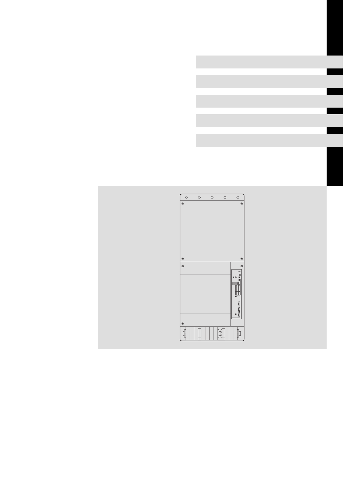
X1
X3
LO HI
GNDA1A2A3A4ST1ST25934763
28E1E32
E2E4E5391
X4
X5
7
62
X6
+UGL1 L2 L3 BR1 BR2 U V W-UG
34
33
K32
K31
5
1
5
1
1
5
X11
X8
X9
X10
9300vec055
Page 4

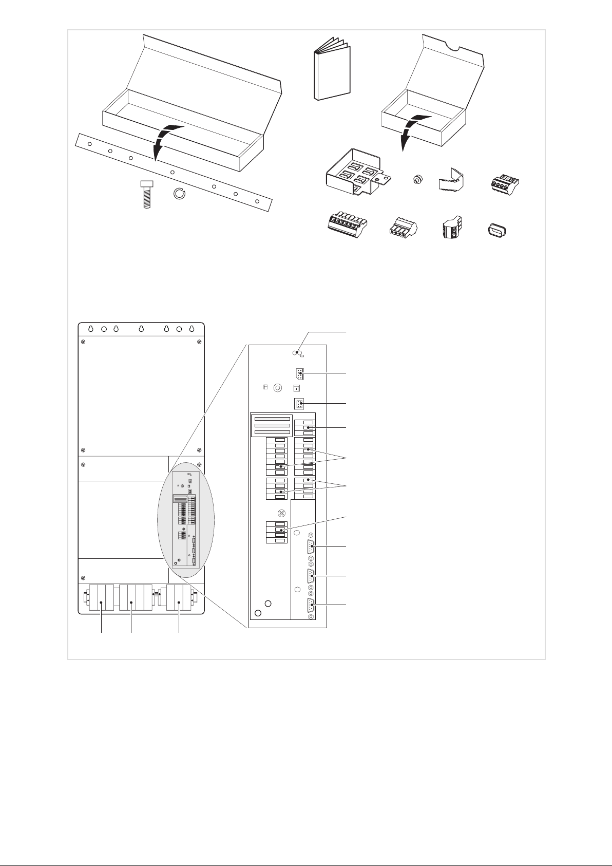
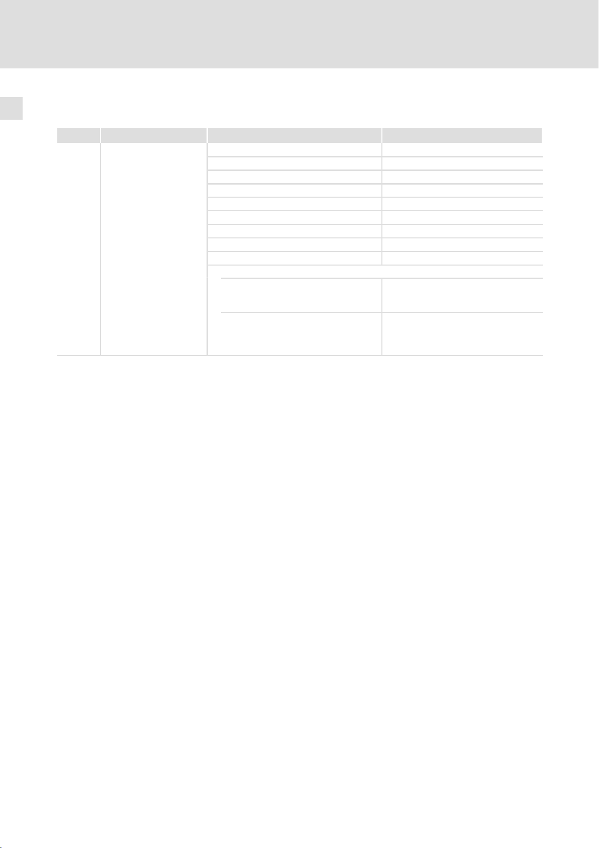
Lieferumfang
Beschreibung Verwendung Anzahl
0 Frequenzumrichter 9300 vector 1
1 Montageanleitung 1
2 Montageschiene 2
3 Innensechskantschraube M8 × 25 mm
4 Federring M8 12
5 EMV−Schirmblech für geschirmte Steuerleitungen 1
6 Kreuzschlitzschraube M4 × 12 mm Befestigung EMV−Schirmblech 5 2
7 Schirmklammer Anbindung der Leitungsschirme am Schirmblech 3
8 Klemmenleiste 4−polig Sicherheitsrelais KSR an X11 1 ^ 41
9 Klemmenleiste 7−polig Digitale Eingänge und Ausgänge an X5 2 ^ 41
: Klemmenleiste 4−polig Analoge Eingänge und Ausgänge an X6 2 ^ 41
; Klemmenleiste 3−polig Systembus (CAN) an X4 1 ^ 47
< Schutzabdeckung Schutz für nicht verwendete Sub−D−Buchsen 4
Befestigung des Antriebsreglers mit der Montageschiene 2 auf der Montageplatte
12
Anschlüsse und Schnittstellen
Beschreibung Funktion
Leistungsklemmen
Leistungsklemmen Anschluss an den DC−Zwischenkreis ^ 33
Leistungsklemmen Motoranschluss ^ 36
X1 Steuerschnittstelle Steckplatz für z. B. Keypad
X3 Jumper Einstellung analoges Eingangssignal an X6/1, X6/2 ^ 46
X4 Steuerklemmen Systembus (CAN) ^ 47
X5 Steuerklemmen Digitale Eingänge und Ausgänge ^ 39
X6 Steuerklemmen Analoge Eingänge und Ausgänge ^ 39
X8 Sub−D−Buchse Inkrementalgebereingang ^ 49
X9 Sub−D−Buchse
X10 Sub−D−Buchse Leitfrequenzausgang ^ 51
X11 Steuerklemmen Sicherheitsrelais K
Netzanschluss Antriebsregler für 400 V ^ 31
Netzanschluss Antriebsregler für 500 V ^ 32
Inkrementalgebereingang ^ 50
Leitfrequenzeingang ^ 51
SR
^ 27
^ 40
^ 41
Statusanzeigen
Position LED rot LED grün Betriebszustand
aus ein Antriebsregler freigegeben
ein ein Netz eingeschaltet und automatischer Start gesperrt
aus blinkt langsam Antriebsregler gesperrt
aus ein Motordaten−Identifizierung ist aktiv
blinkt schnell aus Unterspannung oder Überspannung
blinkt langsam aus Störung aktiv
0Abb. 0Tab. 0
4
l
EDKVF9338 DE/EN/FR 4.0
Page 5

Inhalt i
1 Über diese Dokumentation 7 . . . . . . . . . . . . . . . . . . . . . . . . . . . . . . . . . . . . . . . . . . . . . . . . .
1.1 Dokumenthistorie 7 . . . . . . . . . . . . . . . . . . . . . . . . . . . . . . . . . . . . . . . . . . . . . . . . . . . .
1.2 Zielgruppe 7 . . . . . . . . . . . . . . . . . . . . . . . . . . . . . . . . . . . . . . . . . . . . . . . . . . . . . . . . . .
1.3 Informationen zur Gültigkeit 8 . . . . . . . . . . . . . . . . . . . . . . . . . . . . . . . . . . . . . . . . . . .
1.4 Verwendete Konventionen 9 . . . . . . . . . . . . . . . . . . . . . . . . . . . . . . . . . . . . . . . . . . . .
1.5 Verwendete Hinweise 10 . . . . . . . . . . . . . . . . . . . . . . . . . . . . . . . . . . . . . . . . . . . . . . . . .
2 Sicherheitshinweise 11 . . . . . . . . . . . . . . . . . . . . . . . . . . . . . . . . . . . . . . . . . . . . . . . . . . . . . . .
2.1 Allgemeine Sicherheits− und Anwendungshinweise für Lenze−Antriebsregler 11 . .
2.2 Motor thermisch überwachen 15 . . . . . . . . . . . . . . . . . . . . . . . . . . . . . . . . . . . . . . . . . .
2.2.1 Beschreibung 15 . . . . . . . . . . . . . . . . . . . . . . . . . . . . . . . . . . . . . . . . . . . . . . . .
2.2.2 Parametrieren 16 . . . . . . . . . . . . . . . . . . . . . . . . . . . . . . . . . . . . . . . . . . . . . . .
2.3 Restgefahren 17 . . . . . . . . . . . . . . . . . . . . . . . . . . . . . . . . . . . . . . . . . . . . . . . . . . . . . . . .
3 Technische Daten 18 . . . . . . . . . . . . . . . . . . . . . . . . . . . . . . . . . . . . . . . . . . . . . . . . . . . . . . . . . .
3.1 Allgemeine Daten und Einsatzbedingungen 18 . . . . . . . . . . . . . . . . . . . . . . . . . . . . .
3.2 Sicherheitsrelais KSR 20 . . . . . . . . . . . . . . . . . . . . . . . . . . . . . . . . . . . . . . . . . . . . . . . . . .
3.3 Bemessungsdaten 21 . . . . . . . . . . . . . . . . . . . . . . . . . . . . . . . . . . . . . . . . . . . . . . . . . . . .
3.3.1 Antriebsregler für 400 V Netzspannung 21 . . . . . . . . . . . . . . . . . . . . . . . . . .
3.3.2 Antriebsregler für 400 V / 500 V Netzspannung 22 . . . . . . . . . . . . . . . . . . .
4 Mechanische Installation 24 . . . . . . . . . . . . . . . . . . . . . . . . . . . . . . . . . . . . . . . . . . . . . . . . . . .
4.1 Wichtige Hinweise 24 . . . . . . . . . . . . . . . . . . . . . . . . . . . . . . . . . . . . . . . . . . . . . . . . . . .
4.2 Abmessungen 25 . . . . . . . . . . . . . . . . . . . . . . . . . . . . . . . . . . . . . . . . . . . . . . . . . . . . . . .
4.3 Bohrungen an der Montageplatte durchführen 26 . . . . . . . . . . . . . . . . . . . . . . . . . . .
4.4 Montageschienen an der Montageplatte befestigen 27 . . . . . . . . . . . . . . . . . . . . . .
4.5 Antriebsregler auf der Montageplatte befestigen 28 . . . . . . . . . . . . . . . . . . . . . . . . .
5 Elektrische Installation 29 . . . . . . . . . . . . . . . . . . . . . . . . . . . . . . . . . . . . . . . . . . . . . . . . . . . . .
5.1 EMV−gerechte Installation (Aufbau des CE−typischen Antriebssystems) 29 . . . . . . .
5.2 Netzanschluss beim Antriebsregler für 400 V Netzspannung 31 . . . . . . . . . . . . . . .
5.3 Versorgungs− und Lüfteranschluss beim Antriebsregler für 400 V/500V
Netzspannung 32 . . . . . . . . . . . . . . . . . . . . . . . . . . . . . . . . . . . . . . . . . . . . . . . . . . . . . . .
5.3.1 Netzanschluss 32 . . . . . . . . . . . . . . . . . . . . . . . . . . . . . . . . . . . . . . . . . . . . . . .
5.3.2 Anschluss an den DC−Zwischenkreis (+UG, −UG) 33 . . . . . . . . . . . . . . . . . . .
5.3.3 Lüfteranschluss 34 . . . . . . . . . . . . . . . . . . . . . . . . . . . . . . . . . . . . . . . . . . . . . .
5.4 Motoranschluss 36 . . . . . . . . . . . . . . . . . . . . . . . . . . . . . . . . . . . . . . . . . . . . . . . . . . . . .
5.4.1 Motortemperatur−Überwachung verdrahten 37 . . . . . . . . . . . . . . . . . . . . .
EDKVF9338 DE/EN/FR 4.0
l
5
Page 6

Inhalti
5.5 Steueranschlüsse 39 . . . . . . . . . . . . . . . . . . . . . . . . . . . . . . . . . . . . . . . . . . . . . . . . . . . . .
5.5.1 Wichtige Hinweise 39 . . . . . . . . . . . . . . . . . . . . . . . . . . . . . . . . . . . . . . . . . . . .
5.5.2 Mit aktiver Funktion "Sicher abgeschaltetes Moment" 41 . . . . . . . . . . . . .
5.5.3 Mit deaktivierter Funktion "Sicher abgeschaltetes Moment" 44 . . . . . . . .
5.5.4 Klemmenbelegung 46 . . . . . . . . . . . . . . . . . . . . . . . . . . . . . . . . . . . . . . . . . . .
5.6 Systembus (CAN) verdrahten 47 . . . . . . . . . . . . . . . . . . . . . . . . . . . . . . . . . . . . . . . . . . .
5.7 Rückführsystem verdrahten 48 . . . . . . . . . . . . . . . . . . . . . . . . . . . . . . . . . . . . . . . . . . . .
5.7.1 Wichtige Hinweise 48 . . . . . . . . . . . . . . . . . . . . . . . . . . . . . . . . . . . . . . . . . . . .
5.7.2 Inkrementalgeber mit TTL−Pegel an X8 49 . . . . . . . . . . . . . . . . . . . . . . . . . . .
5.7.3 Inkrementalgeber mit HTL−Pegel an X9 50 . . . . . . . . . . . . . . . . . . . . . . . . . .
5.8 Leitfrequenzeingang / Leitfrequenzausgang verdrahten 51 . . . . . . . . . . . . . . . . . . . .
6 Abschließende Arbeiten 53 . . . . . . . . . . . . . . . . . . . . . . . . . . . . . . . . . . . . . . . . . . . . . . . . . . . .
6.1 Installation überprüfen 53 . . . . . . . . . . . . . . . . . . . . . . . . . . . . . . . . . . . . . . . . . . . . . . .
6.2 Inbetriebnahme vorbereiten 54 . . . . . . . . . . . . . . . . . . . . . . . . . . . . . . . . . . . . . . . . . . .
6
l
EDKVF9338 DE/EN/FR 4.0
Page 7

Über diese Dokumentation
Dokumenthistorie
1 Über diese Dokumentation
1.1 Dokumenthistorie
Was ist neu / was hat sich geändert?
Materialnummer Version Beschreibung
.E^j 4.0 03/2011 TD23 Überarbeitung: Ergänzungen für Softwarestand 8.1 einge-
fügt
13219331 3.0 04/2008 TD23/35/32 Überarbeitung, Fehlerbereinigung
13181372 2.0 02/2007 TD23/31/25 Überarbeitung, Fehlerbereinigung
489169 1.0 06/2004 TD23 Erstausgabe
I Tipp!
Informationen und Hilfsmittel rund um die Lenze−Produkte finden Sie im
Download−Bereich unter
http://www.Lenze.com
1
1.2 Zielgruppe
Diese Dokumentation richtet sich an qualifiziertes Fachpersonal nach IEC 60364.
Qualifiziertes Fachpersonal sind Personen, die für die auszuführenden Tätigkeiten bei der
Aufstellung, Montage, Inbetriebsetzung und dem Betrieb des Produkts über entsprechende Qualifikationen verfügen.
EDKVF9338 DE/EN/FR 4.0
l
7
Page 8
1
Über diese Dokumentation
Informationen zur Gültigkeit
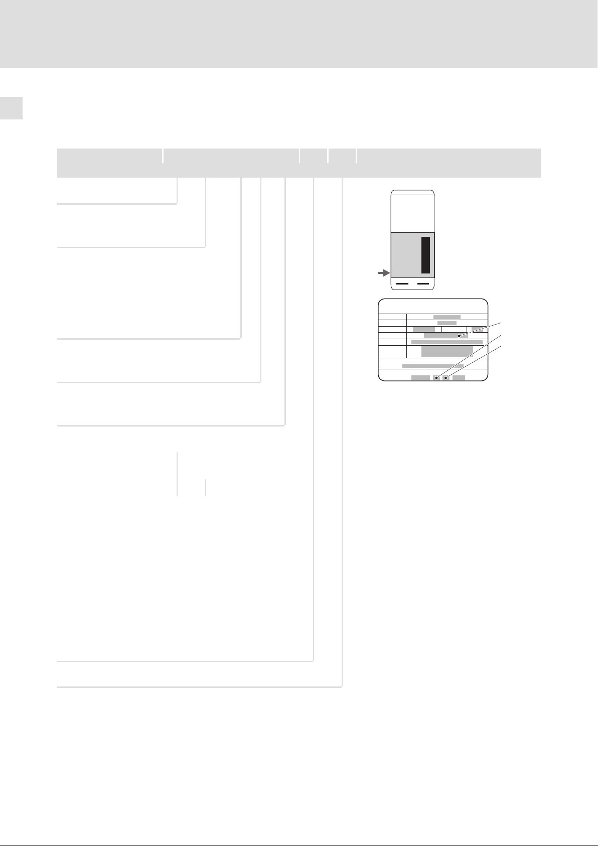
1.3 Informationen zur Gültigkeit
Diese Dokumentation ist gültig für Frequenzumrichter 9300 vector ab dem Gerätestand
Typenschild
EVF 93xx ˘ E V Vxxx 1x 8x
Produktreihe
EVF Frequenzumrichter
Typ Nr. / Leistung
400 V 500 V
9335
110 kW
9336
132 kW
9337
162 kW
9338
200 kW
Bauart
E Einbaugerät
Ausführung
V Vectorgeregelter Frequenzumrichter
132 kW
160 kW
200 kW
250 kW
L
Inverter
Id.-No.:
Prod.-No.:
Type:
Input:
Output:
0045042000129567000005
33.9335VE.1A.70
33 . 9335VE . 1A . 70 . V030
Hans-Lenze-Strasse1
D-31855Aerzen
Madein EC
Ser.-No.:
Variante
Funkentstörfilter A
integriert
– 400 V – –
V030 400 V · –
V060 400 V – ·
V110 400 V ··
V210 400 V / 500 V – –
V240 400 V / 500 V · –
V270 400 V / 500 V – ·
V300 400 V / 500 V ··
Hardwarestand
Softwarestand
Bremstransistor
integriert
8
l
EDKVF9338 DE/EN/FR 4.0
Page 9

Über diese Dokumentation
Verwendete Konventionen
1
1.4 Verwendete Konventionen
Diese Dokumentation verwendet folgende Konventionen zur Unterscheidung verschiedener Arten von Information:
Informationsart Auszeichnung Beispiele/Hinweise
Zahlenschreibweise
Dezimaltrennzeichen sprachabhängig Als Dezimaltrennung werden die für die
Warnhinweise
UL−Warnhinweise
UR−Warnhinweise
Textauszeichnung
Programmname » « PC−Software
Symbole
Seitenverweis ^ Verweis auf eine andere Seite mit zusätzli-
J
O
jeweilige Zielsprache üblichen Zeichen verwendet.
Zum Beispiel: 1234.56 oder 1234,56
Werden nur in der englischen Sprache verwendet.
Zum Beispiel: »Engineer«, »Global Drive
Control« (GDC)
chen Informationen
Zum Beispiel: ^ 16 = siehe Seite 16
EDKVF9338 DE/EN/FR 4.0
l
9
Page 10

1
Über diese Dokumentation
Verwendete Hinweise
1.5 Verwendete Hinweise
Um auf Gefahren und wichtige Informationen hinzuweisen, werden in dieser Dokumentation folgende Piktogramme und Signalwörter verwendet:
Sicherheitshinweise
Aufbau der Sicherheitshinweise:
} Gefahr!
(kennzeichnet die Art und die Schwere der Gefahr)
Hinweistext
(beschreibt die Gefahr und gibt Hinweise, wie sie vermieden werden kann)
Piktogramm und Signalwort Bedeutung
{ Gefahr!
} Gefahr!
( Stop!
Gefahr von Personenschäden durch gefährliche elektrische
Spannung
Hinweis auf eine unmittelbar drohende Gefahr, die den Tod oder
schwere Verletzungen zur Folge haben kann, wenn nicht die
entsprechenden Maßnahmen getroffen werden.
Gefahr von Personenschäden durch eine allgemeine Gefahrenquelle
Hinweis auf eine unmittelbar drohende Gefahr, die den Tod oder
schwere Verletzungen zur Folge haben kann, wenn nicht die
entsprechenden Maßnahmen getroffen werden.
Gefahr von Sachschäden
Hinweis auf eine mögliche Gefahr, die Sachschäden zur Folge
haben kann, wenn nicht die entsprechenden Maßnahmen getroffen werden.
Anwendungshinweise
Piktogramm und Signalwort Bedeutung
) Hinweis!
I Tipp!
,
Wichtiger Hinweis für die störungsfreie Funktion
Nützlicher Tipp für die einfache Handhabung
Verweis auf andere Dokumentation
10
l
EDKVF9338 DE/EN/FR 4.0
Page 11

Sicherheitshinweise
Allgemeine Sicherheits− und Anwendungshinweise für Lenze−Antriebsregler
2 Sicherheitshinweise
2.1 Allgemeine Sicherheits− und Anwendungshinweise für Lenze−Antriebsregler
(gemäß Niederspannungsrichtlinie 2006/95/EG)
Zu Ihrer persönlichen Sicherheit
Wenn Sie die folgenden grundlegenden Sicherheitsmaßnahmen missachten, kann dies zu
schweren Personenschäden und Sachschäden führen:
ƒ Das Produkt ausschließlich bestimmungsgemäß verwenden.
ƒ Das Produkt niemals trotz erkennbarer Schäden in Betrieb nehmen.
ƒ Das Produkt niemals unvollständig montiert in Betrieb nehmen.
ƒ Keine technischen Änderungen am Produkt vornehmen.
ƒ Nur das für das Produkt zugelassene Zubehör verwenden.
2
ƒ Nur Original−Ersatzteile des Herstellers verwenden.
ƒ Alle am Einsatzort geltenden Unfallverhütungsvorschriften, Richtlinien und Gesetze
beachten.
ƒ Nur qualifiziertes Fachpersonal die Arbeiten zum Transport, zur Installation, zur
Inbetriebnahme und zur Instandhaltung ausführen lassen.
– IEC 364 bzw. CENELEC HD 384 oder DIN VDE 0100 und IEC−Report 664 oder
DIN VDE 0110 und nationale Unfallverhütungsvorschriften beachten.
– Qualifiziertes Fachpersonal im Sinne dieser grundsätzlichen Sicherheitshinweise
sind Personen, die mit Aufstellung, Montage, Inbetriebsetzung und Betrieb des
Produkts vertraut sind und die über die ihrer Tätigkeit entsprechenden
Qualifikationen verfügen.
ƒ Alle Vorgaben dieser Dokumentation beachten.
– Dies ist Voraussetzung für einen sicheren und störungsfreien Betrieb sowie für das
Erreichen der angegebenen Produkteigenschaften.
– Die in dieser Dokumentation dargestellten verfahrenstechnischen Hinweise und
Schaltungsausschnitte sind Vorschläge, deren Übertragbarkeit auf die jeweilige
Anwendung überprüft werden muss. Für die Eignung der angegebenen Verfahren
und Schaltungsvorschläge übernimmt Lenze Automation GmbH keine Gewähr.
ƒ Lenze−Antriebsregler (Frequenzumrichter, Servo−Umrichter, Stromrichter) und
zugehörige Komponenten können während des Betriebs − ihrer Schutzart
entsprechend − spannungsführende, auch bewegliche oder rotierende Teile haben.
Oberflächen können heiß sein.
– Bei unzulässigem Entfernen der erforderlichen Abdeckung, bei unsachgemäßem
Einsatz, bei falscher Installation oder Bedienung besteht die Gefahr von schweren
Personen− oder Sachschäden.
– Weitere Informationen entnehmen Sie der Dokumentation.
ƒ Im Antriebsregler treten hohe Energien auf. Deshalb bei Arbeiten am Antriebsregler
EDKVF9338 DE/EN/FR 4.0
unter Spannung immer eine persönliche Schutzausrüstung tragen (Körperschutz,
Kopfschutz, Augenschutz, Gehörschutz, Handschutz).
l
11
Page 12

2
Sicherheitshinweise
Allgemeine Sicherheits− und Anwendungshinweise für Lenze−Antriebsregler
Bestimmungsgemäße Verwendung
Antriebsregler sind Komponenten, die zum Einbau in elektrische Anlagen oder Maschinen
bestimmt sind. Sie sind keine Haushaltsgeräte, sondern als Komponenten ausschließlich
für die Verwendung zur gewerblichen Nutzung bzw. professionellen Nutzung im Sinne der
EN 61000−3−2 bestimmt.
Bei Einbau der Antriebsregler in Maschinen ist die Inbetriebnahme (d. h. die Aufnahme des
bestimmungsgemäßen Betriebs) solange untersagt, bis festgestellt wurde, dass die Maschine den Bestimmungen der EG−Richtlinie 2006/42/EG (Maschinenrichtlinie) entspricht; EN 60204 beachten.
Die Inbetriebnahme (d. h. die Aufnahme des bestimmungsgemäßen Betriebs) ist nur bei
Einhaltung der EMV−Richtlinie (2004/108/EG) erlaubt.
Die Antriebsregler erfüllen die Anforderungen der Niederspannungsrichtlinie
2006/95/EG. Die harmonisierte Norm EN 61800−5−1 wird für die Antriebsregler angewendet.
Die technischen Daten und die Angaben zu Anschlussbedingungen entnehmen Sie dem
Leistungsschild und der Dokumentation. Halten Sie diese unbedingt ein.
Warnung: Die Antriebsregler sind Produkte, die nach EN 61800−3 in Antriebssysteme der
Kategorie C2 eingesetzt werden können. Diese Produkte können im Wohnbereich Funkstörungen verursachen. In diesem Fall kann es für den Betreiber erforderlich sein, entsprechende Maßnahmen durchzuführen.
Transport, Einlagerung
Beachten Sie die Hinweise für Transport, Lagerung und sachgemäße Handhabung.
Halten Sie die klimatischen Bedingungen gemäß den technischen Daten ein.
Aufstellung
Sie müssen die Antriebsregler nach den Vorschriften der zugehörigen Dokumentation aufstellen und kühlen.
Die Umgebungsluft darf den Verschmutzungsgrad 2 nach EN 61800−5−1 nicht überschreiten.
Sorgen Sie für sorgfältige Handhabung und vermeiden Sie mechanische Überlastung. Verbiegen Sie bei Transport und Handhabung weder Bauelemente noch ändern Sie Isolationsabstände. Berühren Sie keine elektronischen Bauelemente und Kontakte.
Antriebsregler enthalten elektrostatisch gefährdete Bauelemente, die Sie durch unsachgemäße Handhabung leicht beschädigen können. Beschädigen oder zerstören Sie keine
elektrischen Komponenten, da Sie dadurch Ihre Gesundheit gefährden können!
12
l
EDKVF9338 DE/EN/FR 4.0
Page 13

Sicherheitshinweise
Allgemeine Sicherheits− und Anwendungshinweise für Lenze−Antriebsregler
Elektrischer Anschluss
Beachten Sie bei Arbeiten an unter Spannung stehenden Antriebsreglern die geltenden
nationalen Unfallverhütungsvorschriften (z. B. VBG 4).
Führen Sie die elektrische Installation nach den einschlägigen Vorschriften durch (z. B. Leitungsquerschnitte, Absicherungen, Schutzleiteranbindung). Zusätzliche Hinweise enthält die Dokumentation.
Die Dokumentation enthält Hinweise für die EMV−gerechte Installation (Schirmung, Erdung, Anordnung von Filtern und Verlegung der Leitungen). Beachten Sie diese Hinweise
ebenso bei CE−gekennzeichneten Antriebsreglern. Der Hersteller der Anlage oder Maschine ist verantwortlich für die Einhaltung der im Zusammenhang mit der EMV−Gesetzgebung geforderten Grenzwerte. Um die am Einbauort geltenden Grenzwerte für Funkstöraussendungen einzuhalten, müssen Sie die Antriebsregler in Gehäuse
(z. B. Schaltschränke) einbauen. Die Gehäuse müssen einen EMV−gerechten Aufbau ermöglichen. Achten Sie besonders darauf, dass z. B. Schaltschranktüren möglichst umlaufend metallisch mit dem Gehäuse verbunden sind. Öffnungen oder Durchbrüche durch
das Gehäuse auf ein Minimum reduzieren.
Lenze−Antriebsregler können einen Gleichstrom im Schutzleiter verursachen. Wird für den
Schutz bei einer direkten oder indirekten Berührung an einem 3−phasig versorgten Antriebsregler ein Differenzstromgerät (RCD) verwendet, ist auf der Stromversorgungsseite
des Antriebsreglers nur ein Differenzstromgerät (RCD) vom Typ B zulässig. Wird der Antriebsregler 1−phasig versorgt, ist auch ein Differenzstromgerät (RCD) vom Typ A zulässig.
Neben der Verwendung eines Differenzstromgerätes (RCD) können auch andere Schutzmaßnahmen angewendet werden, wie z. B. Trennung von der Umgebung durch doppelte
oder verstärkte Isolierung oder Trennung vom Versorgungsnetz durch einen Transformator.
2
Betrieb
Sie müssen Anlagen mit eingebauten Antriebsreglern ggf. mit zusätzlichen Überwachungs− und Schutzeinrichtungen gemäß den jeweils gültigen Sicherheitsbestimmungen
ausrüsten (z. B. Gesetz über technische Arbeitsmittel, Unfallverhütungsvorschriften). Sie
dürfen die Antriebsregler an Ihre Anwendung anpassen. Beachten Sie dazu die Hinweise
in der Dokumentation.
Nachdem der Antriebsregler von der Versorgungsspannung getrennt ist, dürfen Sie spannungsführende Geräteteile und Leistungsanschlüsse nicht sofort berühren, weil Kondensatoren aufgeladen sein können. Beachten Sie dazu die entsprechenden Hinweisschilder
auf dem Antriebsregler.
Halten Sie während des Betriebs alle Schutzabdeckungen und Türen geschlossen.
Hinweis für UL−approbierte Anlagen mit eingebauten Antriebsreglern: UL warnings sind
Hinweise, die nur für UL−Anlagen gelten. Die Dokumentation enthält spezielle Hinweise zu
UL.
Sicherheitsfunktionen
Bestimmte Varianten der Antriebsregler unterstützen Sicherheitsfunktionen (z. B. "Sicher
abgeschaltetes Moment", ehem. "Sicherer Halt") nach den Anforderungen der EG−Richtlinie "Maschinen" 2006/42/EG. Beachten Sie unbedingt die Hinweise in der Dokumentation zur integrierten Sicherheitstechnik.
Wartung und Instandhaltung
Die Antriebsregler sind wartungsfrei, wenn die vorgeschriebenen Einsatzbedingungen
eingehalten werden.
EDKVF9338 DE/EN/FR 4.0
l
13
Page 14

2
Sicherheitshinweise
Allgemeine Sicherheits− und Anwendungshinweise für Lenze−Antriebsregler
Entsorgung
Metalle und Kunststoffe zur Wiederverwertung geben. Bestückte Leiterplatten fachgerecht entsorgen.
Beachten Sie unbedingt die produktspezifischen Sicherheits− und Anwendungshinweise
in dieser Anleitung!
14
l
EDKVF9338 DE/EN/FR 4.0
Page 15

2.2 Motor thermisch überwachen
2.2.1 Beschreibung
) Hinweis!
Ab Softwarestand 8.1 verfügen die Antriebsregler 9300 vector über eine
2
I
xt−Funktion, um den angeschlossenen Motor sensorlos thermisch zu
überwachen.
ƒ Die I
ƒ Die berechnete Motorauslastung wird beim Netzschalten gespeichert.
ƒ Die I
2
xt−Überwachung basiert auf einem mathematischen Modell, das aus
den erfassten Motorströmen eine thermische Motorauslastung berechnet.
2
xt−Überwachung ist trotzdem kein Motorvollschutz, da andere
Einflüsse auf die Motorauslastung nicht erfasst werden können, wie
veränderte Kühlungsbedingungen (z. B. Kühlluftstrom unterbrochen oder zu
warm).
Sicherheitshinweise
Motor thermisch überwachen
Beschreibung
2
2
× t−Belastung des Motors wird vom Antriebsregler kontinuierlich berechnet und in
Die I
C0066 angezeigt.
2
Die I
x t−Überwachung ist so ausgelegt, dass bei einem Motor mit einer thermischen Mo-
tor−Zeitkonstante von 5 min, einem Motorstrom von 1,5 x I
und einer Auslöseschwelle
r
von 100 % die Überwachung nach 179 s auslöst.
Durch zwei einstellbare Auslöseschwellen können Sie unterschiedliche Reaktionen festlegen.
ƒ Einstellbare Reaktion OC8 (TRIP, Warnung, Aus).
– Die Reaktion wird in C0606 eingestellt.
– Die Auslöseschwelle wird in C0127 eingestellt.
– Die Reaktion OC8 kann beispielsweise für eine Vorwarnung genutzt werden.
ƒ Feste Reaktion OC6−TRIP.
– Die Auslöseschwelle wird in C0120 eingestellt.
Verhalten der I2 x t−Überwachung Bedingung
Die I2 x t−Überwachung wird deaktiviert.
Es wird C0066 = 0 % und
MCTRL−LOAD−I2XT = 0,00 % gesetzt.
Die I2 x t−Überwachung wird angehalten.
Der aktuelle Wert in C0066 und am Ausgang MCTRL−
LOAD−I2XT wird eingefroren.
Die I2 x t−Überwachung ist deaktiviert.
Die Motorauslastung wird in C0066 angezeigt.
Bei C0120 = 0 % und C0127 = 0 % die Reglersperre setzen.
Bei C0120 = 0 % und C0127 = 0 % die Reglerfreigabe
erteilen.
C0606 = 3 (Off) und C0127 > 0 % setzen.
) Hinweis!
EDKVF9338 DE/EN/FR 4.0
Eine Fehlermeldung OC6 oder OC8 lässt sich erst zurücksetzen, wenn die
I2 × t−Belastung die eingestellte Auslöseschwelle um 5 % unterschritten hat.
l
15
Page 16
2
Sicherheitshinweise
Motor thermisch überwachen
Parametrieren
2.2.2 Parametrieren
Parametrierung
Codestelle Bedeutung Wertebereich Lenze−Einstellung
C0066 Anzeige der I2xt−Auslastung des Motors 0 ... 250 % −
C0120 Schwelle: Auslösung Fehler "OC6" 0 ... 120 % 0 %
C0127 Schwelle: Auslösung Fehler "OC8" 0 ... 120 % 0 %
C0128 Thermische Zeitkonstante des Motors 0.1 ... 50.0 min 5.0 min
C0606 Reaktion auf Fehler "OC8" Trip, Warnung, Off Warnung
Auslösezeit berechnen
ȡ
t +*(C0128) @ ln
ȧ
Ȣ
ƒ Die thermische Belastungsfähigkeit des Motors wird durch die thermische
1 *
ǒ
I
M
I
r
y ) 1
Ǔ
2
@ 100
ȣ
ȧ
Ȥ
IMAktueller Motorstrom
I
Motor−Bemessungsstrom
r
y C0120 oder C0127
Motor−Zeitkonstante (C0128) ausgedrückt. Entnehmen Sie den Wert den
Bemessungsdaten des Motors oder fragen Sie den Hersteller des Motors.
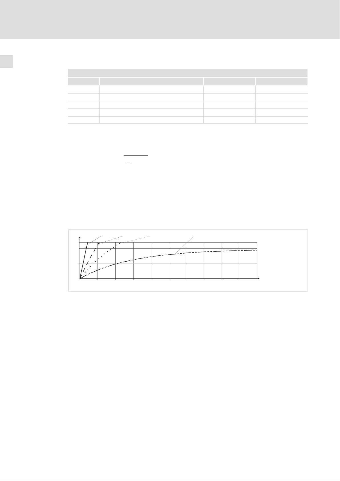
Auslösezeit im Diagramm ablesen
Diagramm zur Ermittlung der Auslösezeiten bei einem Motor mit einer thermischen Motor−Zeitkonstante von 5 min:
2
I t [%]
120
100
50
Abb. 2−1 I2 × t−Überwachung: Auslösezeiten bei unterschiedlichen Motorströmen und Auslöseschwellen
I =3×I
mot r
0
0 100 200 300 400 500 600 700 800 900
I =2×I
mot r
Imot Motorstrom
Motor−Bemessungsstrom
I
r
2
I
tI2t−Belastung
t Zeit
I =1.5×I
mot r
I=1×I
mot r
1000
t [s]
9300std105
16
l
EDKVF9338 DE/EN/FR 4.0
Page 17

2.3 Restgefahren
Personenschutz
ƒ Überprüfen Sie vor Arbeiten am Antriebsregler, ob alle Leistungsklemmen
spannungslos sind:
– Nach dem Netzabschalten führen die Leistungsklemmen U, V, W, +U
BR2 und 101 ... 104 noch mindestens 5 Minuten gefährliche Spannung.
– Bei gestopptem Motor führen die Leistungsklemmen L1, L2, L3, U, V, W, +U
BR1, BR2 und 101 ... 104 gefährliche Spannung.
ƒ Der Ableitstrom gegen Erde (PE) ist >3,5 mA. Nach EN 61800−5−1 ist eine
Festinstallation erforderlich.
ƒ Die Betriebstemperatur des Kühlkörpers am Antriebsregler ist > 80 °C:
– Berührung mit dem Kühlkörper führt zu Verbrennungen.
ƒ Während des Parametersatztransfers können die Steuerklemmen des
Antriebsreglers undefinierte Zustände annehmen.
– Deshalb unbedingt vor dem Transfer die Stecker X5 und X6 abziehen. Dadurch ist
sichergestellt, dass der Antriebsregler gesperrt ist, und alle Steuerklemmen den
fest definierten Zustand LOW" haben.
Sicherheitshinweise
Restgefahren
, −UG, BR1,
G
G
2
, −UG,
Geräteschutz
ƒ Häufiges Netzschalten (z. B. Tipp−Betrieb über Netzschütz) kann die
Eingangsstrombegrenzung des Antriebsreglers überlasten und zerstören:
– Deshalb müssen zwischen zwei Einschaltvorgängen mindestens 5 Minuten
vergehen.
– Verwenden Sie bei häufigen sicherheitsbedingten Abschaltungen die
Sicherheitsfunktion "Sicher abgeschaltetes Moment" (STO).
Motorschutz
ƒ Bei bestimmten Einstellungen am Antriebsregler kann der angeschlossene Motor
überhitzt werden:
– Z. B. längerer Betrieb der Gleichstrombremse.
– Längerer Betrieb eigenbelüfteter Motoren bei kleinen Drehzahlen.
Schutz der Maschine/Anlage
ƒ Antriebe können gefährliche Überdrehzahlen erreichen (z. B. Einstellung hoher
Ausgangsfrequenzen bei dafür ungeeigneten Motoren und Maschinen):
– Die Antriebsregler bieten keinen Schutz gegen solche Betriebsbedingungen. Setzen
Sie dafür zusätzliche Komponenten ein.
EDKVF9338 DE/EN/FR 4.0
l 17
Page 18

3
Technische Daten
Allgemeine Daten und Einsatzbedingungen
3 Technische Daten
3.1 Allgemeine Daten und Einsatzbedingungen
Allgemeine Daten
Konformität und Approbation
Konformität
CE 2006/95/EG Niederspannungsrichtlinie
Personenschutz und Geräteschutz
Schutzart
Erdableitstrom IEC/EN 61800−5−1 > 3.5 mA Bestimmungen und Sicherheits-
Isolierung von Steuerschaltkreisen
Isolationsfestigkeit IEC/EN 61800−5−1
Schutzmaßnahmen Gegen Kurzschluss, Erdschluss (erdschlussfest im Betrieb,
EN 60529
NEMA 250 Berührschutz nach Typ 1
IEC/EN 61800−5−1 Sichere Trennung vom Netz durch doppelte (verstärkte) Iso-
IP20
lierung für die Klemmen X1 und X5.
Basisisolierung (einfache Trennstrecke) für die Klemmen X3,
X4, X6, X8, X9, X10 und X11.
< 2000 m Aufstellhöhe: Überspannungskategorie III
> 2000 m Aufstellhöhe: Überspannungskategorie II
eingeschränkt erdschlussfest beim Netzeinschalten), Überspannung, Kippen des Motors, Motor−Übertemperatur (Eingang für PTC oder Thermokontakt)
hinweise beachten!
EMV
Störaussendung EN 61800−3
Störfestigkeit IEC/EN 61800−3 Kategorie C3
Leitungsgeführt, bis 50 m Motorleitungslänge mit Funkentstörfilter: Kategorie C2.
Strahlung, mit Funkentstörfilter und Einbau im Schaltschrank: Kategorie C2
18
l
EDKVF9338 DE/EN/FR 4.0
Page 19

Technische Daten
Allgemeine Daten und Einsatzbedingungen
Einsatzbedingungen
Umgebungsbedingungen
Klimatisch
Lagerung
Transport IEC/EN 60721−3−2 2K3 (−25 ... +70 °C)
Betrieb
EVF9335 3K3 (0 ... +50 °C)
EVF9336 ... EVF9338 3K3 (0 ... +50 °C)
Verschmutzung EN 61800−5−1 Verschmutzungsgrad 2
Aufstellhöhe < 4000 m üNN
Interner Lüfter 975 m3/h Volumenstrom
Mechanisch
Rüttelfestigkeit EN 61800−5−1
Elektrisch
Netzanschluss
Netzsystem
TT, TN
(mit geerdetem
Sternpunkt)
DC−Verbundbetrieb Möglich bei den Varianten V210, V240, V270, V300
Motoranschluss
Länge der Motorleitung
Geschirmt 100 m
Ungeschirmt 200 m
IEC/EN 60721−3−1
IEC/EN 60721−3−3
1K3 (−20 ... +60 °C) < 6 Monate
1K3 (−25 ... +40 °C) > 6 Monate
> 2 Jahre: Zwischenkreis−Kondensatoren formieren
> +40 °C den Ausgangs−Bemessungsstrom um 2,5 %/°C reduzieren.
> 1000 m üNN den Ausgangs−Bemessungsstrom um
5 %/ 1000 m reduzieren.
Betrieb uneingeschränkt erlaubt.
Bei Netz−Bemessungsspannung und Schaltfrequenz £ 2 kHz
ohne zusätzliche Ausgangsfilter.
Müssen EMV−Bedingungen eingehalten werden, können sich
die zulässigen Leitungslängen ändern.
3
Montagebedingungen
Einbauort Im Schaltschrank
Einbaulage Vertikal
Einbaufreiräume
Abmessungen
Gewichte
EDKVF9338 DE/EN/FR 4.0
^ 24
l
19
Page 20
3
Technische Daten
Sicherheitsrelais KSR
3.2 Sicherheitsrelais K
Klemme Beschreibung Bereich Werte
X11/K32
X11/K31
X11/33
X11/34
Sicherheitsrelais K
1. Abschaltpfad
SR
SR
Spulenspannung bei +20 °C DC 24 V (20 ... 30 V)
Spulenwiderstand bei +20 °C 823 W ±10 %
Bemessungsleistung der Spule ca. 700 mW
Max. Schaltspannung AC 250 V, DC 250 V (0,45 A)
Max. Schaltleistung AC 1500 VA
Max. Schaltstrom (ohmsche Last) AC 6 A (250 V), DC 6 A (50 V)
Empfohlene Minimallast > 50 mW
Max. Schalthäufigkeit 6 Schaltungen pro Minute
Mechanische Lebensdauer 107 Schaltspiele
Elektrische Lebensdauer
bei AC 250 V
(ohmsche Last)
bei DC 24 V
(ohmsche Last)
105 Schaltspiele bei 6 A
6
10
7
10
6 × 10³ Schaltspiele bei 6 A
6
10
1,5 × 10
7
10
Schaltspiele bei 1 A
Schaltspiele bei 0,25 A
Schaltspiele bei 3 A
6
Schaltspiele bei 1 A
Schaltspiele bei 0,1 A
20
l
EDKVF9338 DE/EN/FR 4.0
Page 21
Technische Daten
Bemessungsdaten
Antriebsregler für 400 V Netzspannung
3
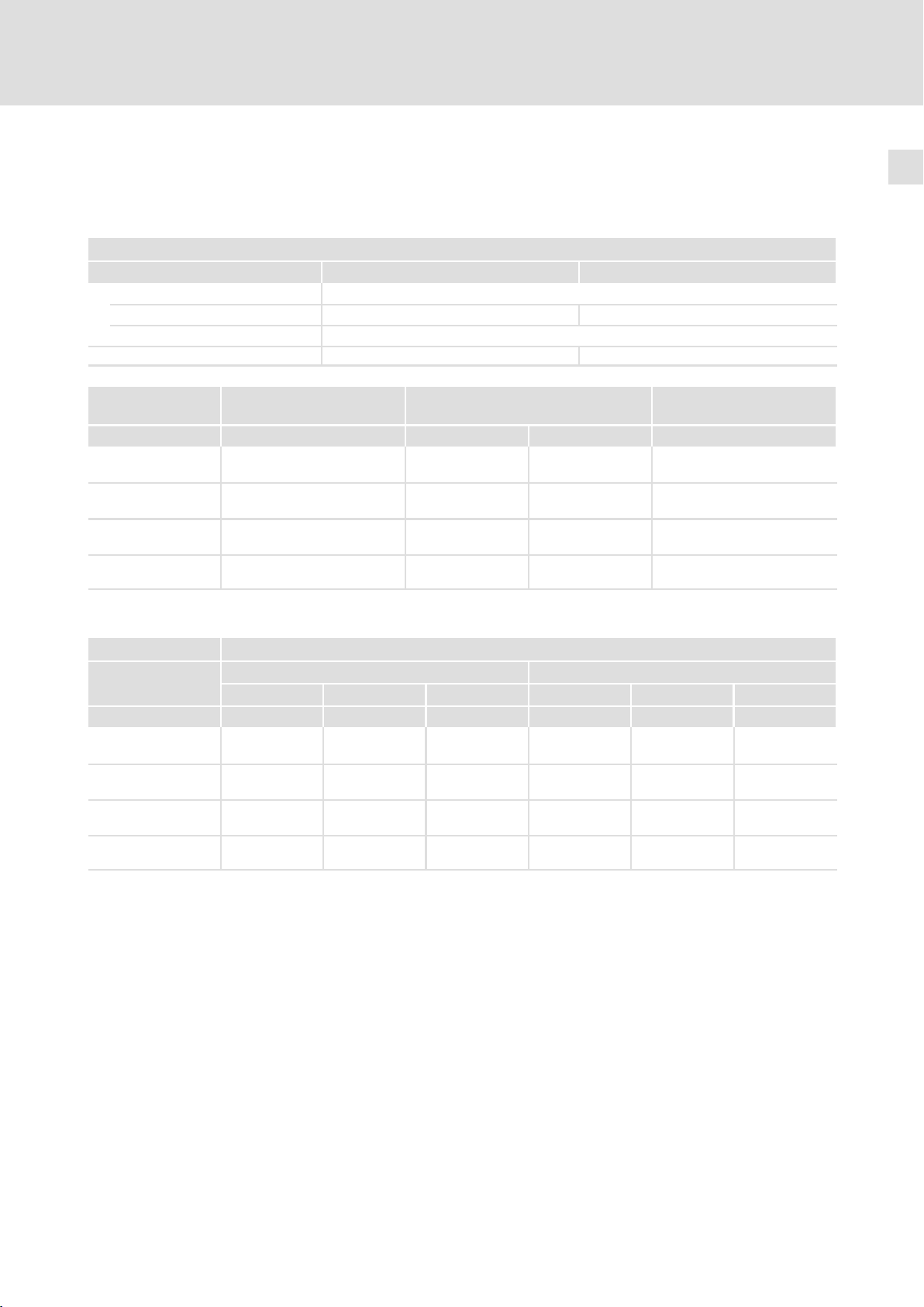
3.3 Bemessungsdaten
3.3.1 Antriebsregler für 400 V Netzspannung
Grundlage der Daten
Spannung Frequenz
Einspeisung
3/PE AC 400 V [UN] 340 V − 0 % ... 456 V + 0 % 45 Hz − 0 % ... 65 Hz + 0 %
DC (alternativ) [UDC] Nicht möglich
Ausgangsspannung [U
9300 Netzstrom
Typ IN [A] P
EVF9335−EV
EVF9335−EVVxxx
EVF9336−EV
EVF9336−EVVxxx
EVF9337−EV
EVF9337−EVVxxx
EVF9338−EV
EVF9338−EVVxxx
2)
2)
2)
2)
1)
Bei einer Schaltfrequenz des Antriebsreglers von 2 kHz
2)
Gerät in der Variante V030, V060 oder V110
9300 Ausgangsströme
1 kHz
Typ I
EVF9335−EV
EVF9335−EVVxxx
EVF9336−EV
EVF9336−EVVxxx
EVF9337−EV
EVF9337−EVVxxx
EVF9338−EV
EVF9338−EVVxxx
3)
3)
3)
3)
Fettdruck = Lenze−Einstellung
1)
2)
3)
N1
Schaltfrequenz des Wechselrichters
Die Ströme gelten für ein periodisches Lastwechselspiel mit maximal 1 Minute Überstromdauer und 2 Minuten
Grundlastdauer mit maximal 75 % I
Gerät in der Variante V030, V060 oder V110
] 3 ~ 0 ... U
OUT
1)
N
Typische Motorleistung
0 ... 300 Hz
Verlustleistung
ASM (4−polig)
[kW] P
N
[hp] P
N
200 110 150 2,8
238 132 200 3,3
285 160 250 4,0
356 200 300 5,0
Bemessungsstrom Maximaler Strom
1)
[A] I
1)
2 kHz
[A] IN4 [A] I
N2
4 kHz
1)
1)
1 kHz
[A] I
M1
1)
2 kHz
[A] I
M2
210 210 210 315 315 315
250 250 250 375 375 375
300 300 270 450 450 405
375 375 330 560 560 495
Nx
V
2)
[kW]
4 kHz
M4
1)
[A]
EDKVF9338 DE/EN/FR 4.0
l
21
Page 22
3
Technische Daten
Bemessungsdaten
Antriebsregler für 400 V / 500 V Netzspannung
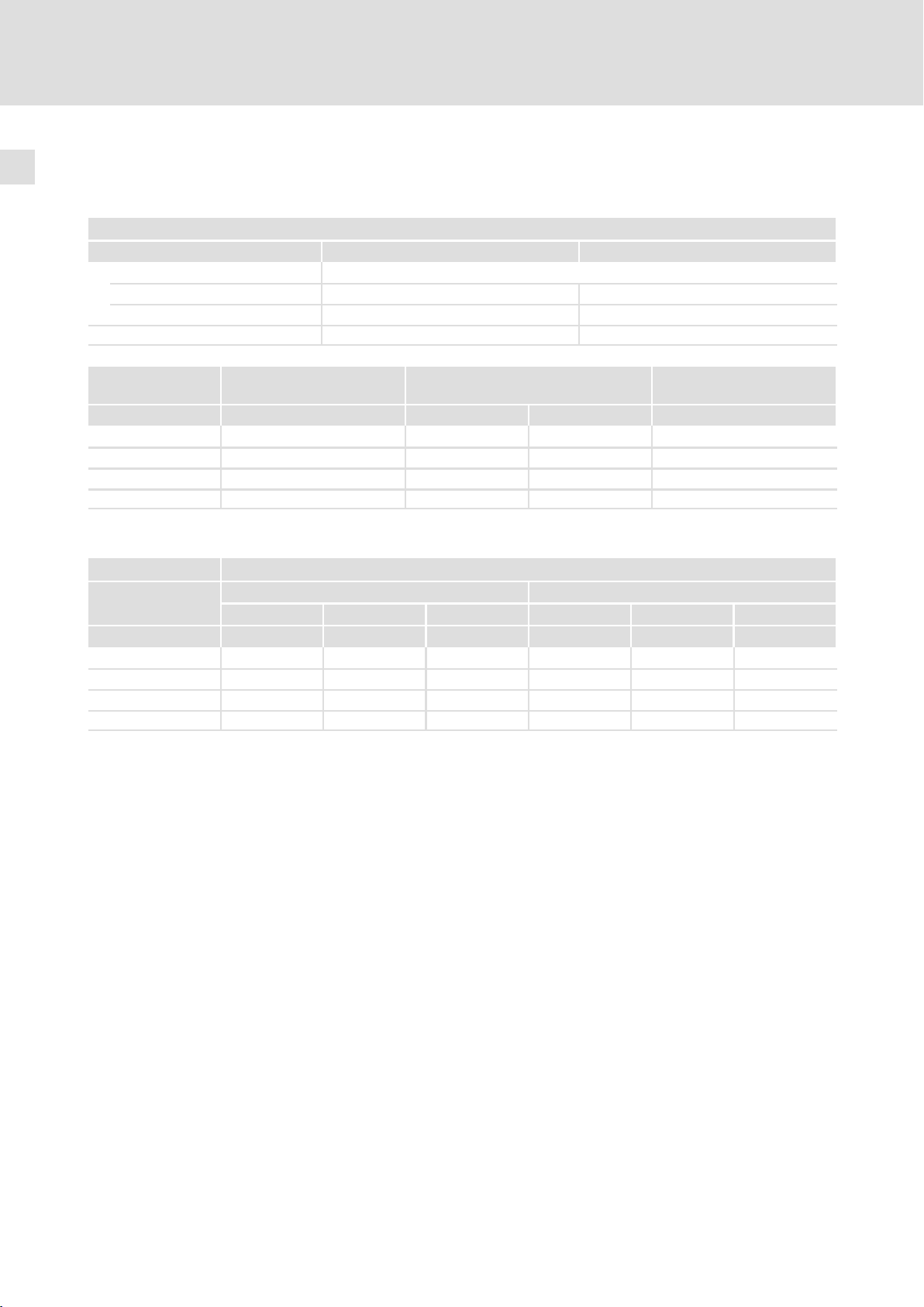
3.3.2 Antriebsregler für 400 V / 500 V Netzspannung
Bemessungsdaten bei 400 V Netzspannung
Grundlage der Daten
Spannung Frequenz
Einspeisung
3/PE AC 400 V [UN] 340 V − 0 % ... 577 V + 0 % 45 Hz − 0 % ... 65 Hz + 0 %
DC 565 V (alternativ) [UDC] DC 480 V − 0 % ... 800 V + 0 % ˘
Ausgangsspannung [U
9300 Netzstrom
Typ IN [A] P
EVF9335−EVVxxx
EVF9336−EVVxxx
EVF9337−EVVxxx
EVF9338−EVVxxx
2)
2)
2)
2)
1)
Bei einer Schaltfrequenz des Antriebsreglers von 2 kHz
2)
Gerät in der Variante V210, V240, V270 oder V300
9300 Ausgangsströme
1 kHz
Typ I
EVF9335−EVVxxx
EVF9336−EVVxxx
EVF9337−EVVxxx
EVF9338−EVVxxx
3)
3)
3)
3)
Fettdruck = Lenze−Einstellung
1)
2)
3)
N1
Schaltfrequenz des Wechselrichters
Die Ströme gelten für ein periodisches Lastwechselspiel mit maximal 1 Minute Überstromdauer und 2 Minuten
Grundlastdauer mit maximal 75 % I
Gerät in der Variante V210, V240, V270 oder V300
] 3 ~ 0 ... U
OUT
1)
N
Typische Motorleistung
ASM (4−polig)
[kW] P
N
200 110 150 2,8
238 132 200 3,3
285 160 250 4,0
356 200 300 5,0
Bemessungsstrom Maximaler Strom
1)
[A] I
1)
2 kHz
[A] IN4 [A] I
N2
4 kHz
1)
210 210 210 315 315 315
250 250 250 375 375 375
300 300 270 450 450 405
375 375 330 560 560 495
Nx
[hp] P
N
1)
1 kHz
[A] I
M1
0 ... 300 Hz
Verlustleistung
1)
2 kHz
[A] I
M2
V
2)
[kW]
4 kHz
M4
1)
[A]
22
l
EDKVF9338 DE/EN/FR 4.0
Page 23
Technische Daten
Bemessungsdaten
Antriebsregler für 400 V / 500 V Netzspannung
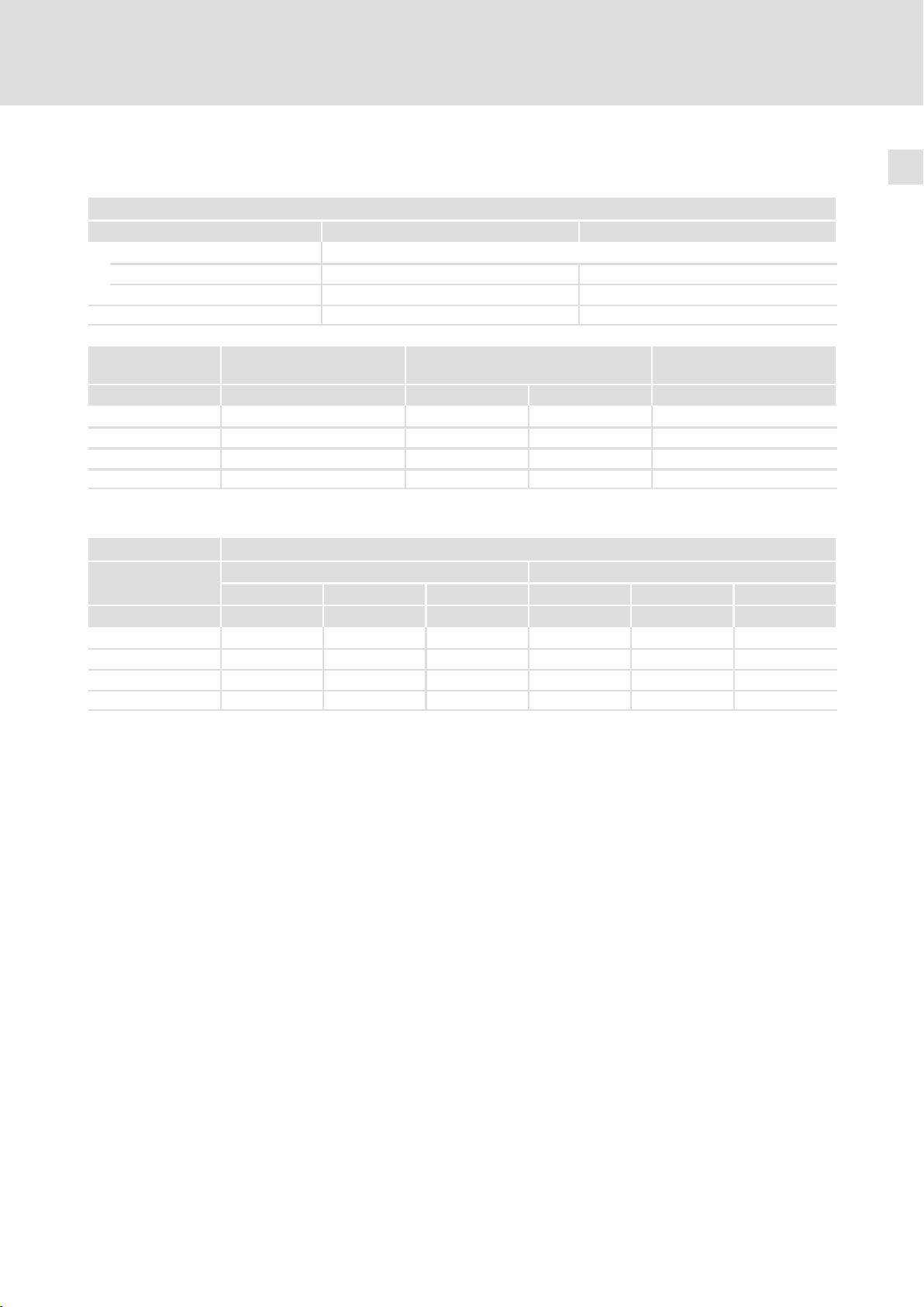
Bemessungsdaten bei 500 V Netzspannung
Grundlage der Daten
Spannung Frequenz
Einspeisung
3/PE AC 500 V [UN] 340 V − 0 % ... 577 V + 0 % 45 Hz − 0 % ... 65 Hz + 0 %
DC 705 V (alternativ) [UDC] DC 480 V − 0 % ... 800 V + 0 % ˘
Ausgangsspannung [U
] 3 ~ 0 ... U
OUT
N
0 ... 300 Hz
3
9300 Netzstrom
1)
Typische Motorleistung
ASM (4−polig)
Typ IN [A] P
EVF9335−EVVxxx
EVF9336−EVVxxx
EVF9337−EVVxxx
EVF9338−EVVxxx
2)
2)
2)
2)
1)
Bei einer Schaltfrequenz des Antriebsreglers von 2 kHz
2)
Gerät in der Variante V210, V240, V270 oder V300
200 132 200 3,0
238 160 250 3,5
285 200 300 4,3
356 250 350 5,3
[kW] P
N
9300 Ausgangsströme
Bemessungsstrom Maximaler Strom
Typ I
EVF9335−EVVxxx
EVF9336−EVVxxx
EVF9337−EVVxxx
EVF9338−EVVxxx
3)
3)
3)
3)
Fettdruck = Lenze−Einstellung
1)
Schaltfrequenz des Wechselrichters
2)
Die Ströme gelten für ein periodisches Lastwechselspiel mit maximal 1 Minute Überstromdauer und 2 Minuten
Grundlastdauer mit maximal 75 % I
3)
Gerät in der Variante V210, V240, V270 oder V300
1)
1 kHz
[A] I
N1
210 210 210 315 315 315
250 250 250 375 375 375
300 300 270 450 450 405
375 375 330 560 560 495
1)
2 kHz
[A] IN4 [A] I
N2
Nx
4 kHz
1)
1 kHz
[hp] P
N
1)
[A] I
M1
2 kHz
M2
Verlustleistung
[kW]
V
2)
1)
[A] I
4 kHz
M4
1)
[A]
EDKVF9338 DE/EN/FR 4.0
l
23
Page 24

4
Mechanische Installation
Wichtige Hinweise
4 Mechanische Installation
I Tipp!
ƒ Lenze empfiehlt den Einbau einer Luftschleuse. Mit der Luftschleuse wird
die erwärmte Kühlluft direkt aus dem Schaltschrank abgeführt.
– Best.−Nr. E93ZWL
ƒ Eine Bohrschablone zum Markieren der Bohrlöcher steht als dxf−Datei im
Internet zur Verfügung, im Bereich "Downloads" unter www.Lenze.de.
4.1 Wichtige Hinweise
Masse der Geräte
9300 Ohne Funkentstörfilter A Mit integriertem Funkentstörfilter A
Typ [kg] [kg]
EVF9335−EV 160 175
EVF9336−EV 160 175
EVF9337−EV 160 175
EVF9338−EV 200 215
24
l
EDKVF9338 DE/EN/FR 4.0
Page 25
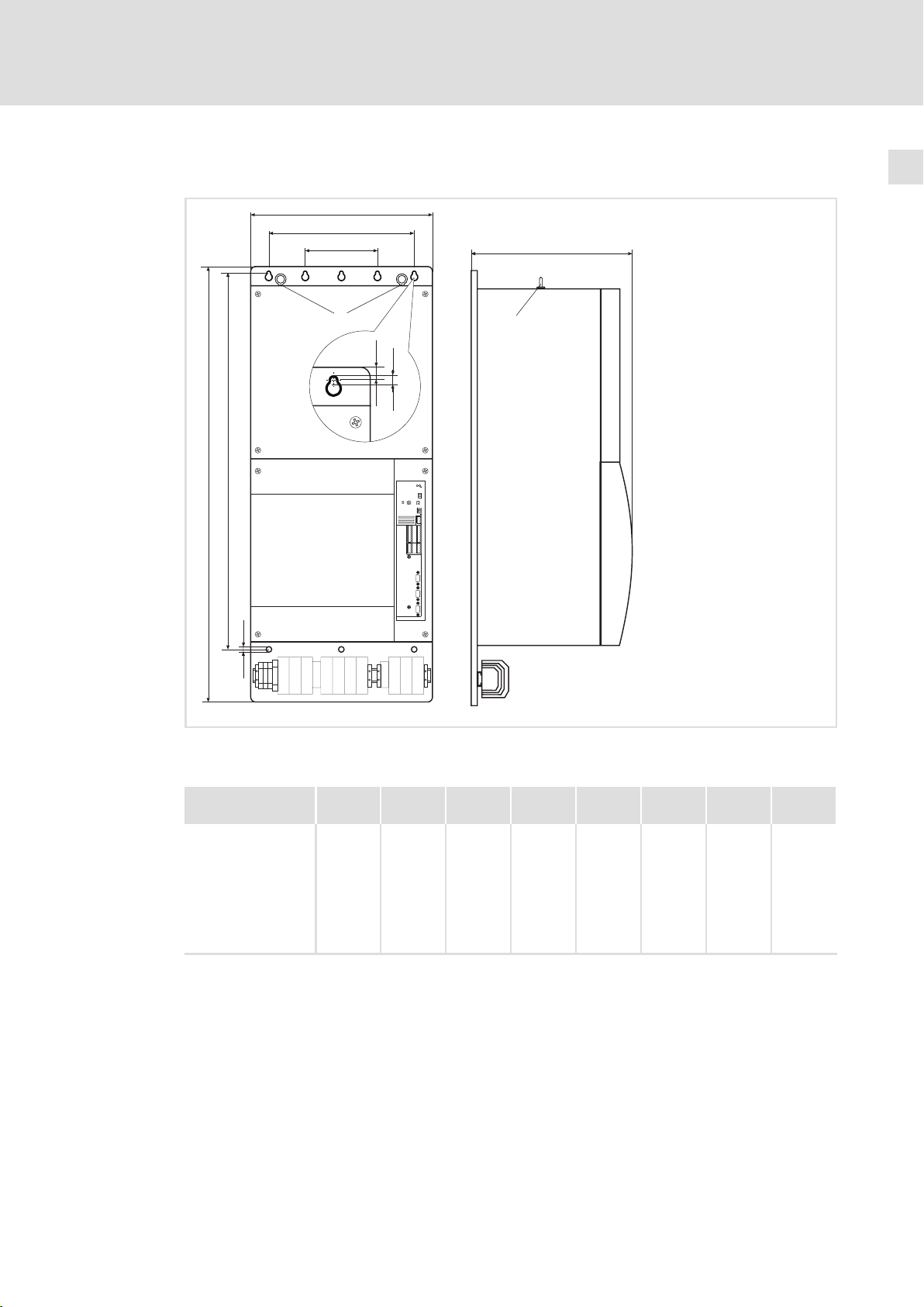
4.2 Abmessungen
b2
d
a
a1
a2
Mechanische Installation
Abmessungen
c
4
b1
b
d
Abb. 4−1 Abmessungen
Ringösen
0
0
0
9300VEC002
EDKVF9338 DE/EN/FR 4.0
Typ a
[mm]
EVF9335−EV
EVF9335−EVVxxx
EVF9336−EV
EVF9336−EVVxxx
EVF9337−EV
EVF9337−EVVxxx
EVF9338−EV
EVF9338−EVVxxx
500 450 225 1145 1005 15 436
a1
[mm]
l
a2
[mm]
b
[mm]
b1
[mm]
b2
[mm]
c
[mm]
d
[mm]
9
(8×)
25
Page 26
4
Mechanische Installation
Bohrungen an der Montageplatte durchführen
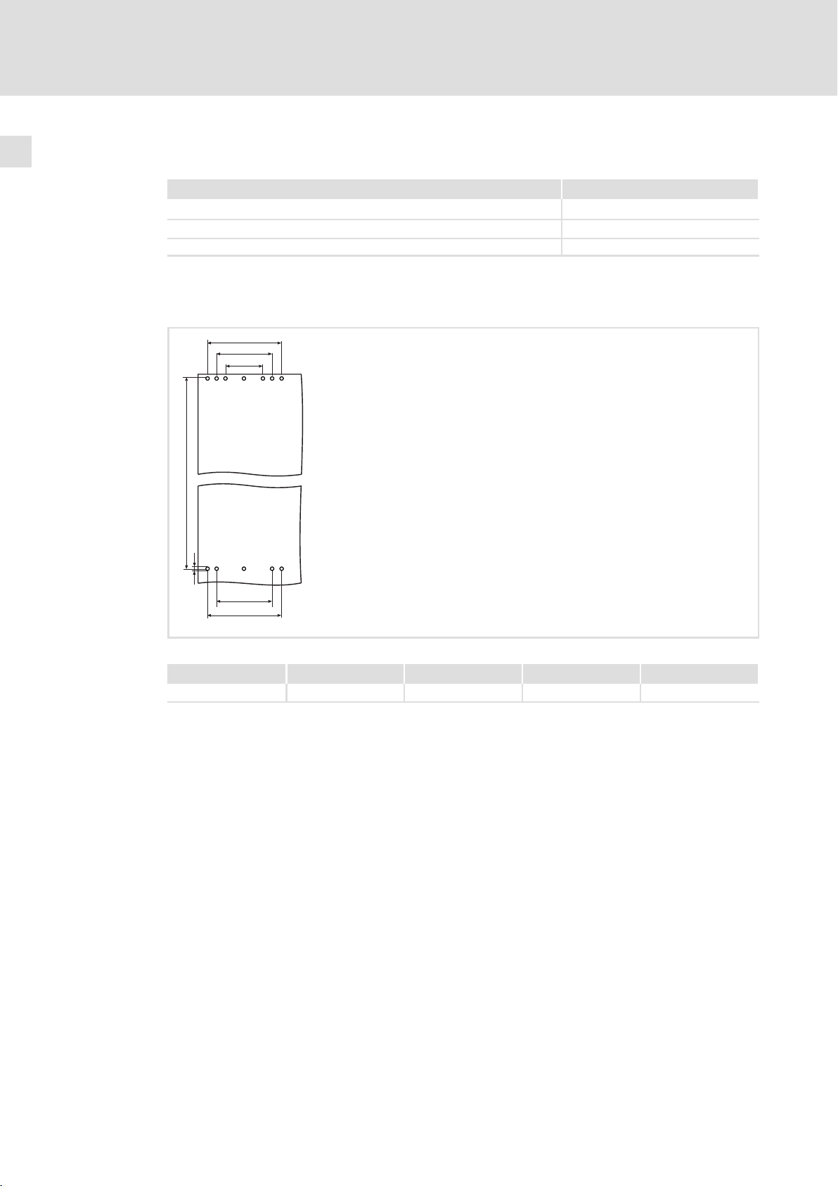
4.3 Bohrungen an der Montageplatte durchführen
Freiraum Mindestabstand
Links/rechts zu einem anderen Antriebsregler 30 mm
Links/rechts zu einer nicht wärmeableitenden Wand 100 mm
Oben/unten 200 mm
Halten Sie die angegebenen Freiräume ein, um eine ausreichende Kühlung des Antriebsreglers sicherzustellen. Beim Einsatz einer Luftschleuse gelten andere Freiräume (siehe
Montageanleitung zur Luftschleuse).
a1
a2
a3
b
d
a2
a1
93vec048
Abb. 4−2 Bohrungen in der Montageplatte zur Befestigung des Antriebsreglers
a1 a2 a3 b d
450 mm 340 mm 225 mm 1005 mm 9 mm (12x)
1. Entsprechend der Abbildung die Bohrungen auf der Montageplatte markieren.
2. Löcher in die Montageplatte bohren.
26
l
EDKVF9338 DE/EN/FR 4.0
Page 27
Mechanische Installation
Montageschienen an der Montageplatte befestigen
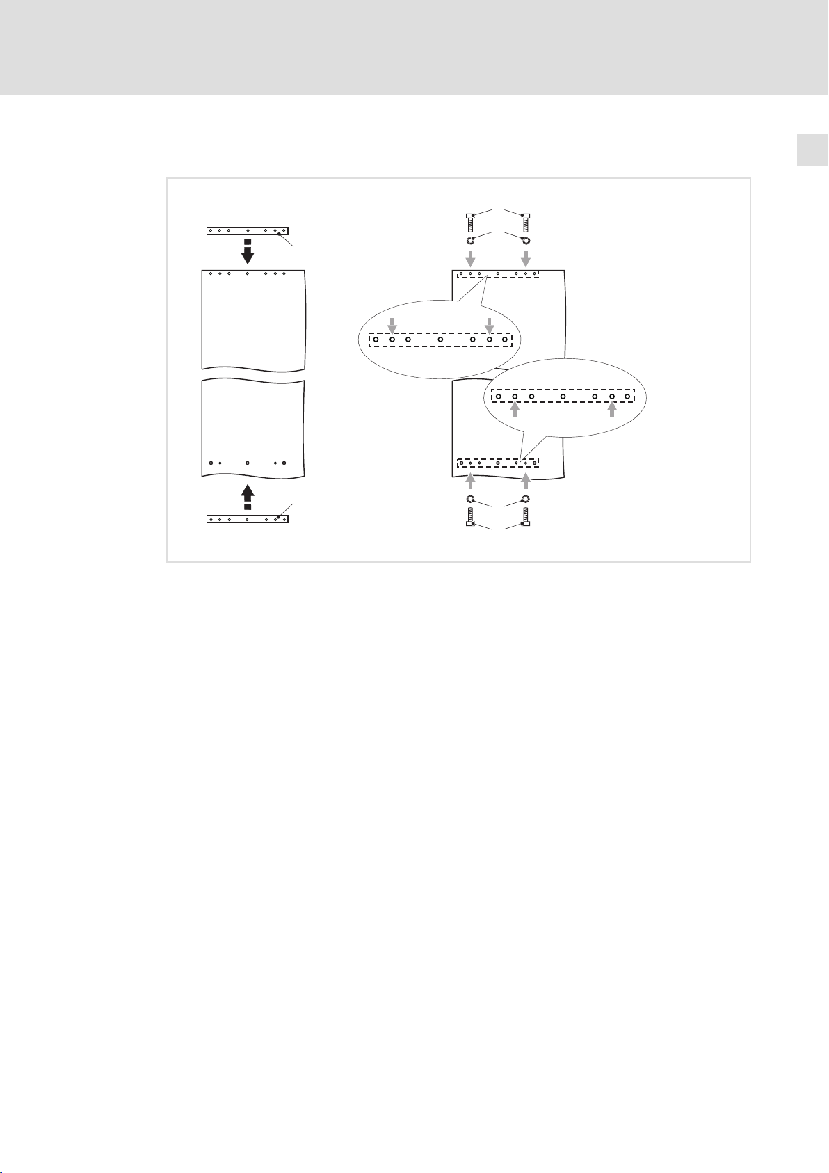
4.4 Montageschienen an der Montageplatte befestigen
4
2
3
0
1
0
3
2
Abb. 4−3 Montageschienen an der Montageplatte befestigen
0 Montageschiene
1 Montageplatte
2 Innensechskantschraube M8 × 25 mm
3 Federring M8
93vec071
1. Montageschienen hinter die Montageplatte halten.
2. Montagesschienen mit je 2 Innensechskantschrauben und Federringen genau an
den gezeigten Punkten festschrauben.
EDKVF9338 DE/EN/FR 4.0
l
27
Page 28
4
Mechanische Installation
Antriebsregler auf der Montageplatte befestigen
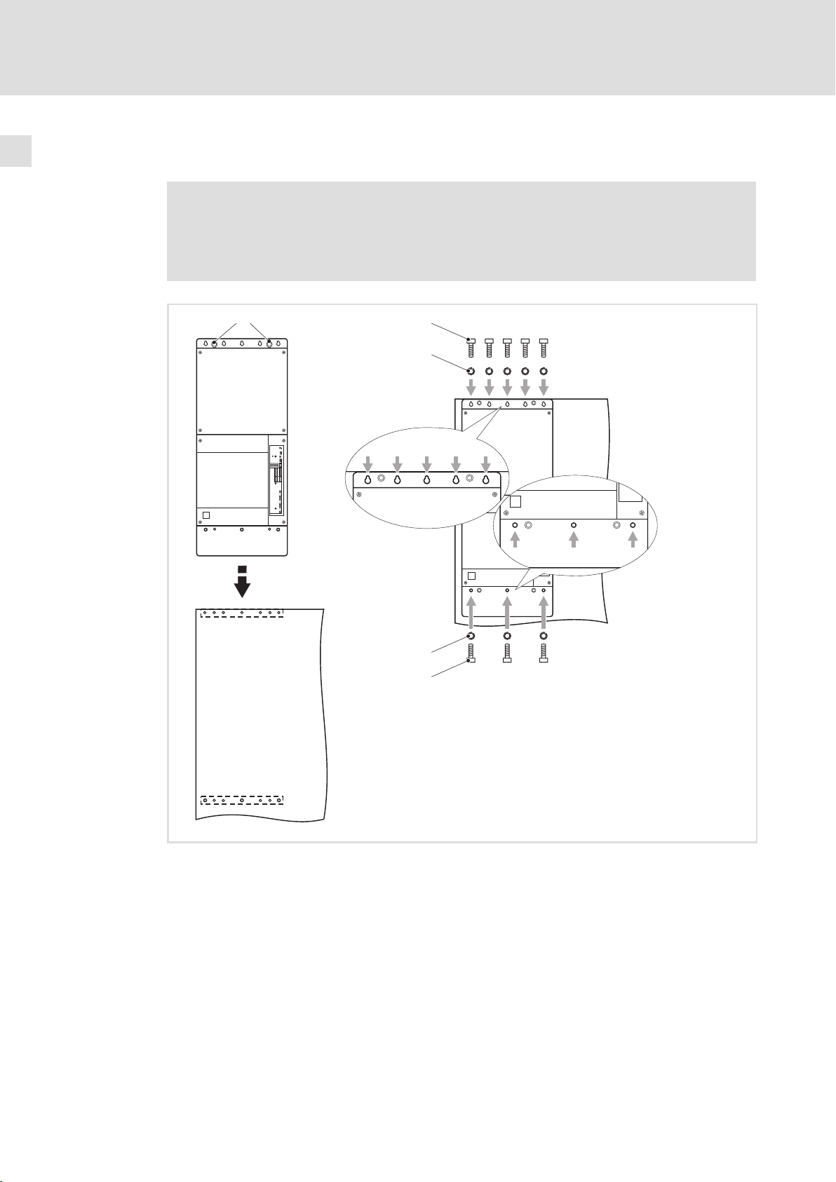
4.5 Antriebsregler auf der Montageplatte befestigen
} Gefahr!
Verletzungsgefahr durch hohes Gewicht des Antriebsreglers.
Transportieren Sie den Antriebsregler ausschließlich an den Ringösen und mit
geeignetem Hebezeug.
0
1
3
4
4
3
2
9300vec070
Abb. 4−4 Antriebsregler auf der Montageplatte befestigen
0 Ringösen 3 8 Innensechskantschrauben M8 × 25 mm
1 Antriebsregler 4 8 Federringe M8
2 Montageplatte
1. Antriebsregler auf die Montageplatte legen.
2. Antriebsregler oben mit 5 und unten mit 3 Innensechskantschrauben und
Federringen genau an den gezeigten Punkten festschrauben.
28
l
EDKVF9338 DE/EN/FR 4.0
Page 29

Elektrische Installation
EMV−gerechte Installation (Aufbau des CE−typischen Antriebssystems)
5 Elektrische Installation
( Stop!
Der Antriebsregler enthält elektrostatisch gefährdete Bauelemente.
Vor Arbeiten im Bereich der Anschlüsse muss sich das Personal von
elektrostatischen Aufladungen befreien.
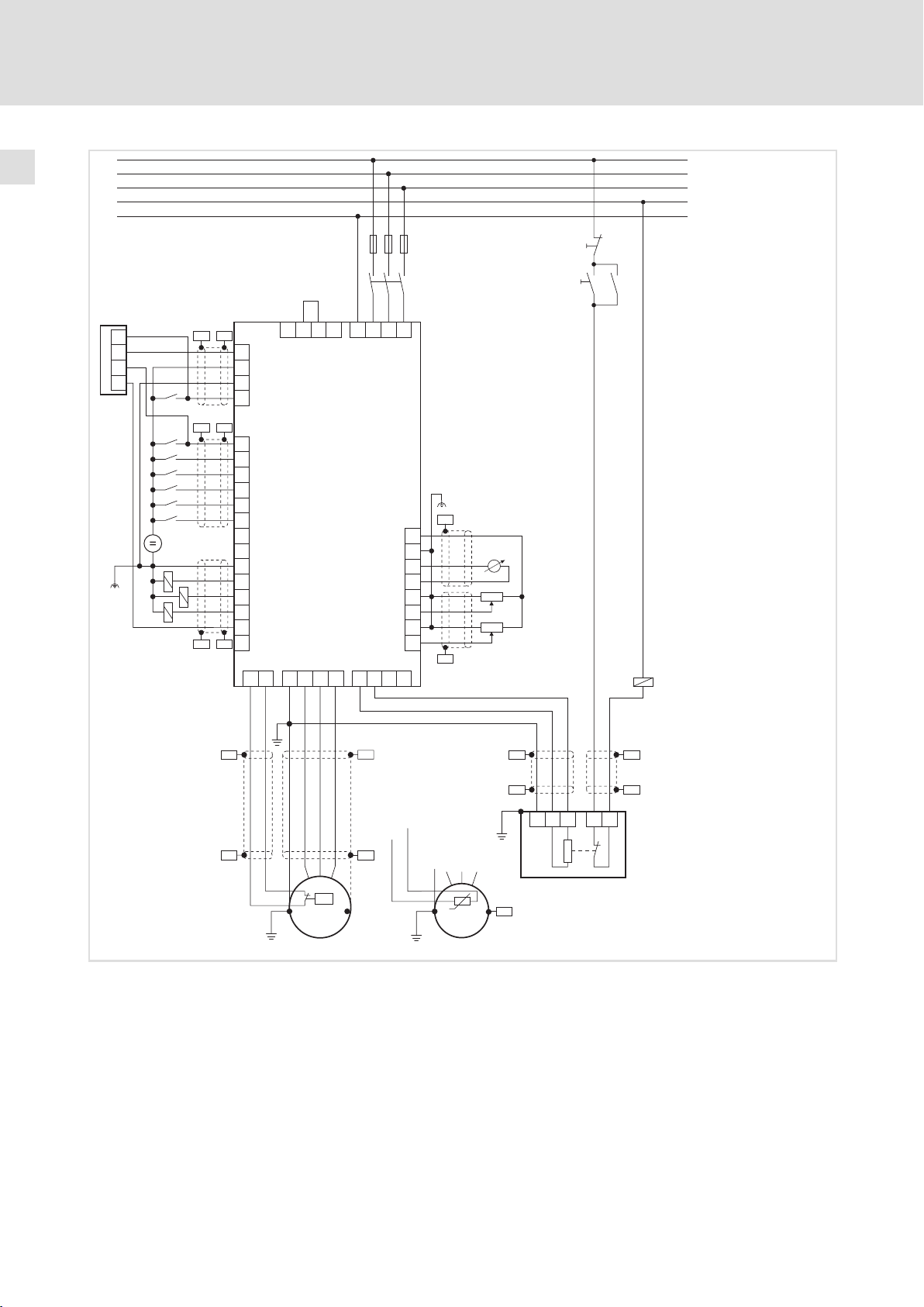
5.1 EMV−gerechte Installation (Aufbau des CE−typischen Antriebssystems)
ƒ Motorleitungen immer getrennt von Netzleitungen und Steuerleitungen verlegen.
ƒ Die Motorleitung möglichst rechtwinklig mit Netzleitungen und Steuerleitungen
kreuzen.
ƒ Optimal wird die Motorleitung frei von Unterbrechungen verlegt.
5
ƒ Alle Komponenten (Antriebsregler, Drosseln) an einen zentralen Erdungspunkt
(PE−Schiene) anschließen.
ƒ Schirme immer großflächig auf die Montageplatte auflegen bzw. die geräteseitigen
Schirmauflagen benutzen.
ƒ Legen Sie den Schirm der Motorleitung immer beidseitig auf − am Antriebsregler und
am Motor.
ƒ Die Leitungen der analogen und digitalen Ein− und Ausgänge geschirmt ausführen.
Wenn kurze (bis 200 mm) nicht abgeschirmte Leitungen verwendet werden, diese
immer verdrillen.
ƒ Die Schirmauflagen der Steuerleitungen sollen min. 50 mm Abstand zu den
Schirmanschlüssen der Motor− und DC−Leitungen aufweisen.
ƒ Bei den digitalen Leitungen muss die Schirmauflage zweiseitig erfolgen.
ƒ Bei den analogen Leitungen muss die Schirmauflage einseitig auf der Umrichterseite
erfolgen.
EDKVF9338 DE/EN/FR 4.0
l
29
Page 30
5
Elektrische Installation
EMV−gerechte Installation (Aufbau des CE−typischen Antriebssystems)
L1
L2
L3
N
PE
F1…F3
K10
X11
K31
K32
ST1
ST2
33
34
X5
28
E1
E2
E3
E4
E5
39
A1
A2
A3
A4
59
101 102 103 104
T1 T2
EVF9335-EV …
EVF9338-EV
PEUVW
PES
+
DC 24 V
PES
PES PES
IN1
Z1
IN2
IN3
IN4
–
PE
PESPES
PE
BR1BR2
L1 L2
+UG -UG
L3
PES
X6
63
7
62
7
4
3
2
1
PES
S2
S1
K10
K10
PE
PES
PES
PE
PES
X8/8
X8/5
PES
J>
M
3~
KTY
PES
M
PE
3~
Abb. 5−1 Beispiel für eine EMV−gerechte Verdrahtung
F1 ... F3 Absicherung
K10 Netzschütz
Z1 Speicherprogrammierbare Steuerung (SPS)
Z2 Bremswiderstand
S1 Netzschütz einschalten
S2 Netzschütz ausschalten
+U
, −U
G
G
Anschluss DC−Zwischenkreis
PES HF−Schirmabschluss durch großflächige Anbindung an PE
PES PES
PES PES
PE
RB2
RB1PE
T2T1
RB
JRB
Z2
9300VEC007
30
l
EDKVF9338 DE/EN/FR 4.0
Page 31

Elektrische Installation
Netzanschluss beim Antriebsregler für 400 V Netzspannung
5
5.2 Netzanschluss beim Antriebsregler für 400 V Netzspannung
( Stop!
Eine ausreichende Zugentlastung liegt in der Verantwortung des Anwenders!
BR2
M6
15-20 Nm
133-176 lb-in
BR1
Anschluss siehe Systemhandbuch 9300 vector
PE
M8
25-30 Nm
L1, L2,
L3
221-264 lb-in
PE
Abb. 5−2 Vorschlag Netzanschluss
BR1, BR2 Betrieb mit Bremswiderstand nur möglich bei Varianten V060 und V110
40 mm
UVWL1 L2 L3
PE
9300VEC003
Sicherungen und Leitungsquerschnitte für die Netzeinspeisung
Typ Installation nach EN 60204−1
2)
L1, L2, L3 [mm2] PE [mm2]
150
1)
2 × 50
150
1)
2 × 50
150
1)
2 × 50
240
1)
2 × 95
EVF9335−EV
EVF9335−EVV030
EVF9335−EVV060
EVF9335−EVV110
EVF9336−EV
EVF9336−EVV030
EVF9336−EVV060
EVF9336−EVV110
EVF9337−EV
EVF9337−EVV030
EVF9337−EVV060
EVF9337−EVV110
EVF9338−EV
EVF9338−EVV030
EVF9338−EVV060
EVF9338−EVV110
1)
2)
Nationale und regionale Vorschriften beachten
Schmelzsicherung
250 A
315 A
315 A
400 A
Mehrleiter; beide Leiter müssen den gleichen Querschnitt haben
Lenze empfiehlt Sicherungen der Betriebsklasse gRL
95
95
95
150
EDKVF9338 DE/EN/FR 4.0
l
31
Page 32

5
Elektrische Installation
Versorgungs− und Lüfteranschluss beim Antriebsregler für 400 V/500V Netzspannung
Netzanschluss
5.3 Versorgungs− und Lüfteranschluss beim Antriebsregler für 400 V/500V Netzspannung
( Stop!
Eine ausreichende Zugentlastung liegt in der Verantwortung des Anwenders!
5.3.1 Netzanschluss
PE
L3
L2
101
102
103
104
M8
25-30 Nm
L1, L2,
L3
221-264 lb-in
Abb. 5−3 Vorschlag Netzanschluss
BR1, BR2 Betrieb mit Bremswiderstand nur möglich bei Varianten V270 und V300
M6
15-20 Nm
PE
133-176 lb-in
Anschluss siehe Systemhandbuch 9300 vector
BR2BR1+UG -UG
40 mm
PE
U
VWL1
9300VEC032
Sicherungen und Leitungsquerschnitte für die Netzeinspeisung
Typ Installation nach EN 60204−1
2)
L1, L2, L3 [mm2] PE [mm2]
150
1)
2 × 50
150
1)
2 × 50
150
1)
2 × 50
240
1)
2 × 95
EVF9335−EVV210
EVF9335−EVV240
EVF9335−EVV270
EVF9335−EVV300
EVF9336−EVV210
EVF9336−EVV240
EVF9336−EVV270
EVF9336−EVV300
EVF9337−EVV210
EVF9337−EVV240
EVF9337−EVV270
EVF9337−EVV300
EVF9338−EVV210
EVF9338−EVV240
EVF9338−EVV270
EVF9338−EVV300
1)
2)
Nationale und regionale Vorschriften beachten
Schmelzsicherung
250 A
315 A
315 A
400 A
Mehrleiter; beide Leiter müssen den gleichen Querschnitt haben
Lenze empfiehlt Sicherungen der Betriebsklasse gRL
95
95
95
150
32
l
EDKVF9338 DE/EN/FR 4.0
Page 33

Elektrische Installation
Versorgungs− und Lüfteranschluss beim Antriebsregler für 400 V/500V Netzspannung
Anschluss an den DC−Zwischenkreis (+UG, −UG)
5.3.2 Anschluss an den DC−Zwischenkreis (+UG, −UG)
ƒ Zur Einhaltung der EMV−Bestimmungen empfiehlt Lenze den Einsatz geschirmter
DC−Zwischenkreisleitungen.
ƒ Schirmschellen sind nicht im Lieferumfang enthalten.
5
PE
L3
L2
101
102
103
104
BR2BR1+UG -UG
0
M6
15-20 Nm
PE
133-176 lb-in
40 mm
Abb. 5−4 Vorschlag Anschluss an +UG und −U
+U
-U
G
G
M8
25-30 Nm
221-264 lb-in
max.
300 mm
1
G
PE
U
VWL1
BR1, BR2 Betrieb mit Bremswiderstand nur möglich bei Varianten V270 und V300
Anschluss siehe Systemhandbuch 9300 vector
0 Schirm der DC−Zwischenkreisleitungen großflächig auf leitender
Schaltschrank−Montageplatte auflegen und mit Schirmschellen festschrauben
1 Metallisch leitende Fläche
Achten Sie auf richtige Polung!
Sicherungen und Leitungsquerschnitte für den Anschluss an den DC−Zwischenkreis
Typ Installation nach EN 60204−1
2)
+UG, −UG [mm2] PE [mm2]
150
2 × 50
150
2 × 50
240
2 × 95
240
2 × 95
1)
1)
1)
1)
95
95
95
150
EVF9335−EVV210
EVF9335−EVV240
EVF9335−EVV270
EVF9335−EVV300
EVF9336−EVV210
EVF9336−EVV240
EVF9336−EVV270
EVF9336−EVV300
EVF9337−EVV210
EVF9337−EVV240
EVF9337−EVV270
EVF9337−EVV300
EVF9338−EVV210
EVF9338−EVV240
EVF9338−EVV270
EVF9338−EVV300
1)
2)
Nationale und regionale Vorschriften beachten
Schmelzsicherung
315 A
350 A
400 A
500 A
Mehrleiter; beide Leiter müssen den gleichen Querschnitt haben
Nur Sicherungen der Betriebsklasse gRL verwenden
9300VEC074
EDKVF9338 DE/EN/FR 4.0
l
33
Page 34

5
Elektrische Installation
Versorgungs− und Lüfteranschluss beim Antriebsregler für 400 V/500V Netzspannung
Lüfteranschluss
5.3.3 Lüfteranschluss
Lüfteranschluss bei Versorgung des Antriebsreglers mit Netzspannung
Brücke legen zwischen den Klemmen bei Betrieb des Antriebsreglers an einem Netz
AC 340 ... 440 V AC 440 ... 577 V
(Auslieferungszustand)
L1 L2
101
102
103
104
9300vec044 9300vec045
101
L1 L2
102
103
104
Lüfteranschluss bei Versorgung des Antriebsreglers über den DC−Zwischenkreis
{ Gefahr!
Bei externer Spannungsversorgung des Lüfters führt Klemme L2 gefährliche
Netzspannung!
Wenn der Antriebsregler über den Zwischenkreis gespeist wird, muss der Lüfter separat
mit Netzspannung versorgt werden (siehe 1). Entfernen Sie in diesem Fall die Brücke zwi-
schen den Klemmen 102 und 103 (siehe 0).
Brücke entfernen
0
101
102
103
104
}
1
L1 L2
101
AC 340 … 440 V
9300vec160 9300vec046 9300vec047
Netzanschluss für den Betrieb des Lüfters an
AC 340 ... 440 V AC 440 ... 577 V
1
L1 L2
102
103
104
101
AC 440 … 577 V
L1 L2
102
103
104
34
l
EDKVF9338 DE/EN/FR 4.0
Page 35

Elektrische Installation
Versorgungs− und Lüfteranschluss beim Antriebsregler für 400 V/500V Netzspannung
Lüfteranschluss
Defekte Sicherung wechseln
Bei externer Spannungsversorgung wird der Lüfter über eine in Klemme 104 integrierte Sicherung geschützt.
0
1
L1 L2
101
102
103
104
Abb. 5−5 Absicherung des Lüfters
0 Sicherungshalter öffnen.
1 Defekte Sicherung aus der Halterung nehmen und durch folgenden Typ ersetzen:
Typ: 500V SA 2A 6.32
Ref. Nr.: P098131
Hersteller: Ferraz Shawmut
5
9300vec161
EDKVF9338 DE/EN/FR 4.0
l
35
Page 36

5
Elektrische Installation
Motoranschluss
Lüfteranschluss
5.4 Motoranschluss
ƒ Zur Einhaltung der EMV−Bestimmungen empfiehlt Lenze den Einsatz geschirmter
Motorleitungen.
ƒ Schirmschellen sind nicht im Lieferumfang enthalten.
( Stop!
Eine ausreichende Zugentlastung liegt in der Verantwortung des Anwenders!
BR2BR1
40 mm
0
M6
15-20 Nm
PE
133-176 lb-in
UVW
PE
U, V, W
M8
25-30 Nm
221-264 lb-in
max.
300 mm
1
Abb. 5−6 Vorschlag Motoranschluss
BR1, BR2 Betrieb mit Bremswiderstand nur möglich bei Varianten V060, V110, V270 und V300
Anschluss siehe Systemhandbuch 9300 vector
0 Schirm der Motorleitungen großflächig auf leitender Schaltschrank−Montageplatte
1 Metallisch leitende Fläche
Achten Sie auf richtige Polung!
Halten Sie die maximale Motorleitungslänge ein!
auflegen und mit Schirmschellen festschrauben
Leitungsquerschnitte für den Motoranschluss
Typ Installation nach EN 60204−1
U, V, W [mm2] PE [mm2]
EVF9335−EV
EVF9335−EVVxxx
EVF9336−EV
EVF9336−EVVxxx
EVF9337−EV
EVF9337−EVVxxx
EVF9338−EV
EVF9338−EVVxxx
1)
Nationale und regionale Vorschriften beachten
Mehrleiter; beide Leiter müssen den gleichen Querschnitt haben
150
2 × 50
150
2 × 50
150
2 × 50
240
2 × 95
1)
1)
1)
1)
9300VEC005
95
95
95
150
36
l
EDKVF9338 DE/EN/FR 4.0
Page 37

Motortemperatur−Überwachung verdrahten
5.4.1 Motortemperatur−Überwachung verdrahten
Der Antriebsregler hat 2 Anschlüsse für die Motortemperatur−Überwachung:
ƒ Klemmen T1, T2 zum Anschluss eines Kaltleiters (PTC) oder Thermokontakts
(Öffner).
ƒ Pin X8/5 und X8/8 des Inkrementalgeber−Eingangs (X8) zum Anschluss eines
Temperatursensors KTY.
Motor mit Kaltleiter (PTC) oder Thermokontakt (Öffner)
Verdrahten Sie T1, T2 nur, wenn der Motor mit einem Kaltleiter (PTC) oder Thermokontakt
(Öffner) ausgestattet ist.
ƒ Eine "offene" Leitung wirkt wie eine Antenne und kann Störungen am
Antriebsregler verursachen.
{ Gefahr!
ƒ Alle Steuerklemmen sind nach dem Anschluss eines Kaltleiters (PTC) oder
eines Thermokontakts nur noch basisisoliert (einfache Trennstrecke).
ƒ Berührsicherheit bei defekter Trennstrecke ist nur durch externe
Maßnahmen gewährleistet, z. B. doppelte Isolierung.
Elektrische Installation
Motoranschluss
5
15 V
2.7 k
T1 T2
PES
PES
3.3 k
7.4 k
MONIT-OH8
U
PE
VW
+UG -UG
PES
PES
T1
T2
J>
PE
M
PES
3~
9300vec139 9300std328
Abb. 5−7 Anschluss Kaltleiter (PTC) oder Thermokontakt (Öffner) an T1, T2
EDKVF9338 DE/EN/FR 4.0
l
37
Page 38

5
Elektrische Installation
Motoranschluss
Motortemperatur−Überwachung verdrahten
Eigenschaften des Anschlusses für die Motortemperatur−Überwachung:
Klemmen T1, T2
Anschluss
Auslösepunkt l Fest (abhängig vom PTC/Thermokontakt)
Bemerkungen l Die Überwachung ist in der Lenze−Einstellung nicht aktiv.
l Kaltleiter (PTC)
– Kaltleiter mit definierter Auslösetemperatur (nach DIN 44081 und DIN 44082)
l Thermokontakt (Öffner)
– Temperaturschalter als Öffner
l PTC: RJ
l Konfigurierbar als Warnung oder Fehler (TRIP)
l Wenn Sie keinen Lenze−Motor einsetzen, empfehlen wir als Kaltleiter einen
> 1600 W
PTC bis 150 °C.
Motor mit Temperatursensor KTY
) Hinweis!
ƒ Wir empfehlen, für die Verdrahtung Lenze−Systemleitungen zu verwenden.
ƒ Bei selbstkonfektionierten Leitungen nur Leitungen mit paarweise
verdrillten und abgeschirmten Adern verwenden.
X8/8
X8/5
PES
PES
T1 T2
X8
X9
X10
U
PE
PE
VW
M
+UG -UG
PES
PES
KTY
PES
3~
Abb. 5−8 Anschluss Temperatursensor KTY am Inkrementalgeber−Eingang X8
Eigenschaften des Anschlusses für die Motortemperatur−Überwachung:
Pin X8/5, X8/8 vom Inkrementalgeber−Eingang (X8)
Anschluss Linearer Temperatursensor KTY
Auslösepunkt l Warnung: Einstellbar
l Fehler (TRIP): Fest bei 150 °C
Bemerkungen l Die Überwachung ist in der Lenze−Einstellung nicht aktiv.
l Der Temperatursensor KTY wird auf Unterbrechung und Kurzschluss überwacht.
9300vec121
38
l
EDKVF9338 DE/EN/FR 4.0
Page 39

5.5 Steueranschlüsse
5.5.1 Wichtige Hinweise
( Stop!
Die Steuerkarte wird zerstört, wenn
ƒ die Spannung zwischen X5/39 und PE oder X6/7 und PE größer 50 V ist,
ƒ bei Versorgung über eine externe Spannungsquelle die Spannung zwischen
Spannungsquelle und X6/7 größer 10 V (Gleichtakt) ist.
Begrenzen Sie die Spannung bevor Sie den Antriebsregler einschalten:
ƒ Legen Sie X5/39, X6/2, X6/4 und X6/7 direkt auf PE oder
ƒ setzen Sie spannungsbegrenzende Bauelemente ein.
ƒ Für einen störungsfreien Betrieb müssen Sie die Steuerleitungen abschirmen:
– Bei Leitungen für die digitalen Eingänge und Ausgänge den Schirm zweiseitig
auflegen.
– Bei Leitungen für die analogen Eingänge und Ausgänge den Schirm einseitig am
Antriebsregler auflegen.
– Ab 200 mm Länge nur geschirmte Leitungen für die analogen und digitalen
Eingänge und Ausgänge verwenden. Unter 200 mm Länge können ungeschirmte,
aber verdrillte Leitungen verwendet werden.
Elektrische Installation
Steueranschlüsse
Wichtige Hinweise
5
EDKVF9338 DE/EN/FR 4.0
l
39
Page 40

5
Elektrische Installation
Steueranschlüsse
Wichtige Hinweise
Schirm auflegen
10
2
3
Abb. 5−9 Anbindung des Leitungsschirms mit Schirmklammer und Zugentlastung mit Kabelbinder
0 Schirmblech
1 Schirmblech mit 2 Schrauben M4 × 12 mm an der Steuerkarte unten festschrauben
2 Leitungsschirm mit Schirmklammer am Schirmblech anbinden
3 Steuerleitung mit Kabelbinder am Schirmblech zugentlasten
Daten der Anschlussklemmen
( Stop!
ƒ Klemmenleisten nur bei vom Netz getrenntem Antriebsregler aufstecken
oder abziehen!
ƒ Klemmenleisten erst verdrahten, dann aufstecken!
ƒ Unbenutzte Klemmenleisten ebenfalls aufstecken, um die Kontakte zu
schützen.
Leitungstyp Aderendhülse Maximaler Leitungs-
starr — 2,5 mm
flexibel ohne Aderendhülse 2,5 mm
flexibel
flexibel
Aderendhülse ohne
Kunststoffhülse
Aderendhülse mit
Kunststoffhülse
querschnitt
2
(AWG 14)
2
(AWG 14)
2
2,5 mm
2,5 mm
(AWG 14)
2
(AWG 14)
Anzugsmoment Abisolier-
länge
0,5 ... 0,6 Nm
(4.4 ... 5.3 lb−in)
9300vec063
5 mm
40
l
EDKVF9338 DE/EN/FR 4.0
Page 41

Elektrische Installation
Steueranschlüsse
Mit aktiver Funktion "Sicher abgeschaltetes Moment"
5
5.5.2 Mit aktiver Funktion "Sicher abgeschaltetes Moment"
(ab Hardwarestand 1x)
Sicherheitshinweise für die Installation der Funktion "Sicher abgeschaltetes Moment"
ƒ Nur qualifiziertes Personal darf die Funktion Sicher abgeschaltetes Moment"
installieren und in Betrieb nehmen.
ƒ Alle sicherheitsrelevanten Leitungen (z. B. Steuerleitung für das Sicherheitsrelais,
Rückmeldekontakt) außerhalb des Schaltschranks unbedingt geschützt verlegen,
z. B. im Kabelkanal. Kurzschlüsse zwischen den einzelnen Leitungen müssen sicher
ausgeschlossen sein.
ƒ Die Verdrahtung des Sicherheitsrelais K
Leitungen ist unbedingt notwendig.
ƒ Der elektrische Bezugspunkt für die Spule des Sicherheitsrelais K
Schutzleitersystem verbunden sein (DIN EN 60204−1 Abs. 9.4.3). Nur so ist der Schutz
gegen fehlerhaften Betrieb durch Erdschlüsse gewährleistet.
mit isolierten Aderendhülsen oder starren
SR
muss mit dem
SR
EDKVF9338 DE/EN/FR 4.0
l
41
Page 42

5
X11
Elektrische Installation
Steueranschlüsse
Mit aktiver Funktion "Sicher abgeschaltetes Moment"
Versorgung über interne Spannungsquelle
ƒ Wird ein frei belegbarer digitaler Ausgang (z. B. X5/A1) fest auf HIGH−Pegel gelgt,
ƒ Für die Versorgung der analogen Eingänge (X6/1, X6/2 und X6/3, X6/4) müssen Sie
+
K
SR
K31K32 33 34
dient er als interne Spannungsquelle. Ein Ausgang ist mit maximal 50 mA belastbar.
– Über einen digitalen Ausgang können Sie das Relais K
und zwei digitale Eingänge
SR
(X5/28 und z. B. X5/E1) mit Spannung versorgen.
– Für die maximale Beschaltung (Relais K
und X5/E1 ... X5/E5, X5/ST1) müssen Sie
SR
zwei digitale Ausgänge parallel schalten und fest auf HIGH−Pegel legen.
einen frei belegbaren analogen Ausgang (z. B. X6/63) fest auf HIGH−Pegel legen.
GND2 +24V+5 V
1
2
3
X5
3k
3k
28
E1 E2 E3 E4
X3
50mA
50mA
50mA
3k
3k
3k
3k
E5
39
A1
A2 A3 A4 ST1
50mA
47k
ST2
59
4
5
6
242R
3.3nF
X6
100k
100k
12
100k
100k
GND1 GND1
3
4
7762
63
IN1 IN2
AIN1 AIN2
13247
10k 10k
IN3
IN4
S1 S2
DIGOUT4
Z1
Abb. 5−10 Verdrahtung digitale und analoge Eingänge/Ausgänge mit aktiver Funktion "Sicher abgeschaltetes
Moment" und interner Spannungsquelle
S1 Impulssperre aufheben (1. Abschaltpfad)
S2 Antriebsregler freigeben (2. Abschaltpfad)
Z1 Speicherprogrammierbare Steuerung (SPS)
Die SPS übernimmt die Überwachung der Funktion ˜Sicher abgeschaltetes Moment˜
X5/A4 Rückmeldung über einen digitalen Ausgang (z. B. DIGOUT4)
Schließer oder Öffner
Z
Verbraucher
Für den Betrieb notwendige Mindestverdrahtung
Klemmenbelegung in der Lenze−Einstellung: ^ 46
AOUT1
AOUTx
AOUT2
9300vec135
42
l
EDKVF9338 DE/EN/FR 4.0
Page 43

K31K32 33 34
X11
Mit aktiver Funktion "Sicher abgeschaltetes Moment"
Versorgung über externe Spannungsquelle
GND2 +24V+5 V
+
K
SR
X5
3k
3k
28
E1 E2 E3 E4
3k
3k
3k
E5
50mA
3k
39
50mA
A1
A2 A3 A4 ST1
50mA
Elektrische Installation
Steueranschlüsse
1
2
3
50mA
47k
ST2
59
X3
4
5
6
242R
X6
100k
3.3nF
12
100k
100k
100k
GND1 GND1
3
4
7762
5
63
IN1 IN2
AIN1 AIN2
13247
10k 10k
IN3
IN4
S1 S2
–
+
DC 24 V
(+18 V … +30 V)
DIGOUT4
Z1
Abb. 5−11 Verdrahtung digitale und analoge Eingänge/Ausgänge mit aktiver Funktion "Sicher abgeschaltetes
Moment" und externer Spannungsquelle
S1 Impulssperre aufheben (1. Abschaltpfad)
S2 Antriebsregler freigeben (2. Abschaltpfad)
Z1 Speicherprogrammierbare Steuerung (SPS)
Die SPS übernimmt die Überwachung der Funktion ˜Sicher abgeschaltetes Moment˜
X5/A4 Rückmeldung über einen digitalen Ausgang (z. B. DIGOUT4)
Schließer oder Öffner
Z
Verbraucher
Für den Betrieb notwendige Mindestverdrahtung
Klemmenbelegung in der Lenze−Einstellung: ^ 46
AOUT1
AOUTx
AOUT2
9300vec136
EDKVF9338 DE/EN/FR 4.0
l
43
Page 44

5
Elektrische Installation
Steueranschlüsse
Mit deaktivierter Funktion "Sicher abgeschaltetes Moment"
5.5.3 Mit deaktivierter Funktion "Sicher abgeschaltetes Moment"
) Hinweis!
Wenn Sie die Funktion "Sicher abgeschaltetes Moment" nicht nutzen, müssen
K31K32 33 34
X11
Sie das Sicherheitsrelais K
Leistungsendstufe mit Spannung versorgt werden.
Versorgung über interne Spannungsquelle
ƒ Wird ein frei belegbarer digitaler Ausgang (z. B. X5/A1) fest auf HIGH−Pegel gelgt,
dient er als interne Spannungsquelle. Ein Ausgang ist mit maximal 50 mA belastbar.
– Über einen digitalen Ausgang können Sie das Relais K
(X5/28 und z. B. X5/E1) mit Spannung versorgen.
– Für die maximale Beschaltung (Relais K
zwei digitale Ausgänge parallel schalten und fest auf HIGH−Pegel legen.
ƒ Für die Versorgung der analogen Eingänge (X6/1, X6/2 und X6/3, X6/4) müssen Sie
einen frei belegbaren analogen Ausgang (z. B. X6/63) fest auf HIGH−Pegel legen.
GND2 +24V+5 V
+
K
SR
X5
3k
28
S1
3k
3k
E1 E2 E3 E4
3k
3k
3k
E5
39
permanent bestromen, damit die Treiber der
SR
und X5/E1 ... X5/E5, X5/ST1) müssen Sie
SR
50mA
50mA
50mA
50mA
47k
A1
A2 A3 A4 ST1
ST2
59
und zwei digitale Eingänge
SR
1
2
3
X3
4
5
6
100k
100k
100k
242R
3.3nF
3
12
X6
AIN1 AIN2
13247
100k
GND1 GND1
4
7762
AOUT1
63
AOUT2
AOUTx
10k 10k
Abb. 5−12 Verdrahtung digitale und analoge Eingänge/Ausgänge mit deaktivierter Funktion "Sicher
abgeschaltetes Moment" bei interner Spannungsquelle
S1 Antriebsregler freigeben
Schließer oder Öffner
Z
Verbraucher
Für den Betrieb notwendige Mindestverdrahtung
Klemmenbelegung in der Lenze−Einstellung: ^ 46
9300vec0137
44
l
EDKVF9338 DE/EN/FR 4.0
Page 45

K31K32 33 34
X11
Mit deaktivierter Funktion "Sicher abgeschaltetes Moment"
Versorgung über externe Spannungsquelle
GND2 +24V+5 V
+
K
SR
X5
3k
3k
28
E1 E2 E3 E4
3k
3k
3k
E5
50mA
3k
39
50mA
A1
A2 A3 A4 ST1
50mA
Elektrische Installation
Steueranschlüsse
1
2
3
50mA
47k
ST2
59
X3
4
5
6
242R
X6
100k
3.3nF
12
100k
100k
100k
GND1 GND1
3
7762
4
5
63
S1
–
+
DC 24 V
(+18 V … +30 V)
AIN1 AIN2
13247
10k 10k
AOUT1
AOUTx
Abb. 5−13 Verdrahtung digitale und analoge Eingänge/Ausgänge mit deaktivierter Funktion "Sicher
abgeschaltetes Moment" bei externer Spannungsquelle
S1 Antriebsregler freigeben
Schließer oder Öffner
Z
Verbraucher
Für den Betrieb notwendige Mindestverdrahtung
Klemmenbelegung in der Lenze−Einstellung: ^ 46
AOUT2
9300vec138
EDKVF9338 DE/EN/FR 4.0
l
45
Page 46

5
Elektrische Installation
Steueranschlüsse
Klemmenbelegung
5.5.4 Klemmenbelegung
Klemme
X11/K32
X11/K31
X11/33 – Spule Sicherheitsrelais K
X11/34 + Spule Sicherheitsrelais K
X5/28 Reglersperre
X5/E1
X5/E2 Linkslauf / Quickstop aufheben HIGH
X5/E3 Festfrequenz 1 aktivieren (JOG1) HIGH
X5/E4 Fehlermeldung setzen (TRIP SET) LOW
X5/E5 Fehlermeldung zurücksetzen
X5/ST1
X5/ST2
X5/A1
X5/A2 Schaltschwelle Q
X5/A3 Betriebsbereit (DCTRL−RDY) HIGH
Sicherheitsrelais K
SR
1. Abschaltpfad
(DCTRL−CINH)
2. Abschaltpfad
Digitale Ein-
gänge
(frei belegbar)
Digitale Ausgänge
(frei belegbar)
Funktion
Fettdruck = Lenze−Einstellung
Rückmeldung Impulssperre
SR
SR
Antriebsregler freigeben und sperren LOW: Regler gesperrt
Rechtslauf / Quickstop aufheben HIGH
(TRIP RESET)
Zusätzlicher digitaler Eingang (E6) HIGH
Fehlermeldung vorhanden LOW
: Istdrehzahl < Soll-
drehzahl in C0017
MIN
Pegel / Zustand Technische Daten
Kontakt geöffnet: Impulssperre aufgehoben (Betrieb)
Kontakt geschlossen: Impulssperre aktiv
Spule nicht bestromt: Impulssperre aktiv
Spule bestromt: Impulssperre
aufgehoben (Betrieb)
HIGH: Regler freigegeben
LOW−HIGH−Flanke
LOW
Siehe Kapitel "Technische Daten"
LOW: 0 ... +3 V
HIGH: +12 ... +30 V
Eingangsstrom bei
+24 V:
8 mA pro Eingang
Einlesen und Bearbeitung der Eingangssignale
1/ms (Mittelwert)
LOW: 0 ... +3 V
HIGH: +12 ... +30 V
Belastbarkeit:
Max. 50 mA pro Ausgang
(Lastwiderstand mindestens 480
W bei +24 V)
X5/A4 Maximalstrom erreicht (DCTRL−IMAX) HIGH
X5/39 – GND2, Bezugspotenzial für digitale Si-
X5/59 – Anschluss externe Spannungsquelle für
X6/1
X6/2
X6/3
X6/4
X6/62 Analoger Aus-
X6/63 Analoger Aus-
X6/7 – GND1, Bezugspotenzial für analoge Sig-
Analoger Eingang 1
Analoger Eingang 2
gang 1
gang 2
gnale
den Stützbetrieb des Antriebsreglers bei
Netzausfall
Eingangsbereich
Spannung
Hauptsollwert
Eingangsbereich
Strom
Eingangsbereich
Spannung
Nicht aktiv
Monitor 1
Drehzahl−Istwert
Monitor 2
Motorstrom−Istwert
nale
6
4
2
Jumper X3
6
4
2
Jumper X3
Jumper X3 hat keinen Einfluss
– Potenzialgetrennt zu
DC 24 V (+18 ... +30 V) Stromaufnahme:
−10 V ... +10 V Auflösung:
5
3
1
−20 mA ... +20 mA Auflösung: 20 mA
5
3
1
−10 V ... +10 V Auflösung: 5 mV
−10 V ... +10 V;
max. 2 mA
−10 V ... +10 V;
max. 2 mA
– –
Aktualisierung der Ausgangssignale 1/ms
GND1
Max. 1 A bei 24 V
5 mV (11 Bit + Vorzeichen)
(10 Bit + Vorzeichen)
(11 Bit + Vorzeichen)
Auflösung: 20 mV
(9 Bit + Vorzeichen)
Auflösung: 20 mV
(9 Bit + Vorzeichen)
46
l
EDKVF9338 DE/EN/FR 4.0
Page 47

5.6 Systembus (CAN) verdrahten
Verdrahtung
Elektrische Installation
Systembus (CAN) verdrahten
5
A
1
93XX 93XX 93XX
GND GND GND GNDLO LO LO LOHI HI HI HIX4 X4 X4PE PE PE PE
120 120
Abb. 5−14 Prinzipielle Verdrahtung des Systembus (CAN)
A
1
A
2
A
3
A
n
X4/GND CAN−GND: Systembus−Bezugspotenzial
X4/LO CAN−LOW: Systembus LOW (Datenleitung)
X4/HI CAN−HIGH: Systembus HIGH (Datenleitung)
A
2
Busteilnehmer 1 (Antriebsregler)
Busteilnehmer 2 (Antriebsregler)
Busteilnehmer 3 (Antriebsregler)
Busteilnehmer n (z. B. SPS), n = max. 63
A
3
A
n
( Stop!
Schließen Sie einen 120 W Abschlusswiderstand am ersten und letzten
Bus−Teilnehmer an.
Spezifikation des Übertragungskabels
Wir empfehlen CAN−Kabel nach ISO 11898−2 zu verwenden:
CAN−Kabel nach ISO 11898−2
Kabeltyp Paarverseilt mit Abschirmung
Impedanz 120 W (95 ... 140 W)
Leitungswiderstand/−querschnitt
Kabellänge £ 300 m £ 70 mW/m / 0.25 0.34 mm2 (AWG22)
Kabellänge 301 1000 m £ 40 mW/m / 0.5 mm2 (AWG20)
Signallaufzeit £ 5 ns/m
9300VEC054
EDKVF9338 DE/EN/FR 4.0
l
47
Page 48

5
5.7 Rückführsystem verdrahten
5.7.1 Wichtige Hinweise
Elektrische Installation
Rückführsystem verdrahten
Wichtige Hinweise
ƒ Sie können entweder am Eingang X8 oder am Eingang X9 einen Inkrementalgeber
anschließen:
– Inkrementalgeber mit TTL−Pegel schließen Sie an X8 an.
– Inkrementalgeber mit HTL−Pegel schließen Sie an X9 an.
ƒ Das Inkrementalgebersignal kann am Leitfrequenzausgang X10 für Folgeantriebe
ausgegeben werden.
) Hinweis!
ƒ Wir empfehlen, für die Verdrahtung Lenze−Systemleitungen zu verwenden.
ƒ Bei selbstkonfektionierten Leitungen nur Leitungen mit paarweise
verdrillten und abgeschirmten Adern verwenden.
48
l
EDKVF9338 DE/EN/FR 4.0
Page 49

Elektrische Installation
Rückführsystem verdrahten
Inkrementalgeber mit TTL−Pegel an X8
5
5.7.2 Inkrementalgeber mit TTL−Pegel an X8
Technische Daten
Bereich Werte
Anschluss am Antriebsregler Steckverbinder: Stift, 9−polig, Sub−D
Anschließbare Inkrementalgeber Inkrementalgeber mit TTL−Pegel
l Geber mit zwei um 90° elektrisch versetzten 5V−Komplementärsigna-
len
l Anschluss der Nullspur möglich (optional)
Eingangsfrequenz 0 ... 500 kHz
Stromaufnahme 6 mA pro Kanal
Interne Spannungsquelle
DC 5 V / max. 200 mA
(X8/4, X8/5)
Verdrahtung
<50m
B
B
A
A
V
CC
GND
Z
KTY
Z
+KTY
-KTY
X8
1
2
3
4
A
5
A
6
B
7
B
8
Z
Z
9
Abb. 5−15 Anschluss Inkrementalgeber mit TTL−Pegel (RS−422)
Signale bei Rechtslauf
Paarweise verdrillte Adern
X8 − Inkrementalgeber mit TTL−Pegel
Steckverbinder: Stift, 9−polig, Sub−D
Pin 1
Signal B A A V
2 3 4 5 6 7 8 9
GND (−KTY) Z Z +KTY B
CC
0,14 mm2 (AWG 26) 1 mm2 (AWG 18) 0,14 mm2 (AWG 26)
9300VEC018
EDKVF9338 DE/EN/FR 4.0
l
49
Page 50

5
Elektrische Installation
Rückführsystem verdrahten
Inkrementalgeber mit HTL−Pegel an X9
5.7.3 Inkrementalgeber mit HTL−Pegel an X9
Technische Daten
Bereich Werte
Anschluss am Antriebsregler Steckverbinder: Stift, 9−polig, Sub−D
Anschließbare Inkrementalgeber Inkrementalgeber mit HTL−Pegel
Eingangsfrequenz 0 ... 200 kHz
Stromaufnahme 5 mA pro Kanal
Versorgung Inkrementalgeber Externe Spannungsquelle
Interne Spannungsquelle
(X9/4, X9/5)
Verdrahtung
<50m
Abb. 5−16 Anschluss Inkrementalgeber mit HTL−Pegel
Signale bei Rechtslauf
Externe Spannungsquelle für den Inkrementalgeber
Paarweise verdrillte Adern
l Zweispurig mit inversen Signalen und Nullspur
l Zweispurig ohne inverse Signale und Nullspur
DC 5 V / max. 200 mA
Summenstrom an X9/4, X9/5 und X10/4, X10/5: max. 200 mA
B
B
A
A
GND
Z
Z
+
X9
1
2
3
4
5
6
7
8
9
A
A
B
B
Z
Z
–
9300VEC020
50
X9 − Inkrementalgeber mit HTL−Pegel
Steckverbinder: Stift, 9−polig, Sub−D
Pin 1
Signal B A A +5 V GND Z Z − B
0,14 mm2 (AWG 26) 1 mm2 (AWG 18) 0,14 mm2 (AWG 26)
2 3 4 5 6 7 8 9
) Hinweis!
Anschluss zweispuriger Inkrementalgeber ohne inverse Signale
(bei HTL−Pegel):
ƒ Legen Sie das Signal A auf Pin X9/2 (A) und das Signal B auf Pin X9/9 (B).
ƒ Verdrahten Sie Pin X9/3 (A) und X9/1) (B) mit dem Pluspol der externen
Spannungsquelle für den Inkrementalgeber.
l
EDKVF9338 DE/EN/FR 4.0
Page 51

Elektrische Installation
Leitfrequenzeingang / Leitfrequenzausgang verdrahten
5.8 Leitfrequenzeingang / Leitfrequenzausgang verdrahten
Technische Daten
Bereich Leitfrequenzausgang X10
Anschluss am Antriebsregler Steckverbinder: Buchse, 9−polig, Sub−D
Pinbelegung Abhängig von der gewählten Grundkonfiguration
Ausgangsfrequenz 0 ... 500 kHz
Signal Zweispurig mit inversen 5 V−Signalen (RS422) und Nullspur
Belastbarkeit Max. 20 mA pro Kanal
(bis zu 3 Folgeantriebe anschließbar)
Besonderheiten Das Ausgangssignal "Enable" an X10/8 schaltet auf LOW, wenn der An-
Interne Spannungsquelle
(X10/4, X10/5)
Bereich Leitfrequenzeingang X9
Anschluss am Antriebsregler Steckverbinder: Stift, 9−polig, Sub−D
Eingangsfrequenz TTL−Pegel: 0 ... 500 kHz
Signal Zweispurig mit inversen Signalen und Nullspur
Auswertung der Signale Über Code C0427
Stromaufnahme Max. 5 mA
Besonderheiten Bei aktivierter Überwachung SD3 wird TRIP oder Warnung ausgelöst,
triebsregler nicht betriebsbereit ist (z. B. vom Netz getrennt). Dadurch
kann beim Folgeantrieb die Überwachung SD3 ausgelöst werden.
DC 5 V / max. 50 mA
Summenstrom an X9/4, X9/5 und X10/4, X10/5: max. 200 mA
HTL−Pegel: 0 ... 200 kHz
Zweispurig ohne inverse Signale und Nullspur (nur bei HTL−Pegel)
wenn das Eingangssignal "Lamp Control" an X9/8 auf LOW schaltet.
Dadurch kann der Antriebsregler reagieren, wenn der Master−Antrieb
nicht betriebsbereit ist.
5
EDKVF9338 DE/EN/FR 4.0
l
51
Page 52

5
Elektrische Installation
Leitfrequenzeingang / Leitfrequenzausgang verdrahten
Verdrahtung
) Hinweis!
ƒ Wir empfehlen, für die Verdrahtung Lenze−Systemleitungen zu verwenden.
ƒ Bei selbstkonfektionierten Leitungen nur Leitungen mit paarweise
verdrillten und abgeschirmten Adern verwenden.
<50m
1
2
3
4
5
6
7
8
9
X9X10
Lamp
control (LC)
A
A
B
B
Z
Z
9300VEC019
Paarweise verdrillte Adern
B
1
2
3
B
A
A
4
GND
Z
Z
Enable (EN)
5
6
7
8
9
Abb. 5−17 Anschluss Leitfrequenzeingang (X9) / Leitfrequenzausgang (X10)
X9 Folgeantrieb (Slave) Signale bei Rechtslauf
X10 Leitantrieb (Master)
X9 − Leitfrequenzeingang
Steckverbinder: Stift, 9−polig, Sub−D
Pin 1
Signal B A A +5 V GND Z Z LC B
X10 − Leitfrequenzausgang
Steckverbinder: Buchse, 9−polig, Sub−D
Pin 1
Signal B A A +5 V GND Z Z EN B
2 3 4 5 6 7 8 9
0,14 mm
(AWG 26)
0,14 mm
(AWG 26)
2
2 3 4 5 6 7 8 9
2
0,5 mm
(AWG 20)
0,5 mm
(AWG 20)
2
2
0,14 mm
(AWG 26)
0,14 mm
(AWG 26)
2
2
0,5 mm
(AWG 20)
0,5 mm
(AWG 20)
2
2
0,14 mm
(AWG 26)
0,14 mm
(AWG 26)
2
2
52
l
EDKVF9338 DE/EN/FR 4.0
Page 53

6 Abschließende Arbeiten
6.1 Installation überprüfen
( Stop!
Zerstörung der digitalen Ausgänge (X5/A1 X5/A4).
Die digitalen Ausgänge sind nicht gegen Fremdspannung geschützt.
Mögliche Folgen:
ƒ Beim Anlegen einer Fremdspannung an X5/A1 X5/A4 können die digitalen
Ausgänge beschädigt werden. Die Steuerkarte funktioniert nicht mehr
fehlerfrei.
Schutzmaßnahmen:
ƒ Niemals Fremdspannung an die Klemmen X5/A1 X5/A4 legen.
Abschließende Arbeiten
Installation überprüfen
6
Überprüfen Sie nach Abschluss der Installation ...
ƒ die Verdrahtung auf Vollständigkeit, Kurzschluss und Erdschluss
ƒ die Versorgung des internen Lüfters (nur 500 V Typen)
– die Position der Brücke ist abhängig von der angelegten Netzspannung
ƒ den Leistungsanschluss:
– Einspeisung über Klemmen L1, L2 und L3 (direkter Netzanschluss)
ƒ den phasenrichtigen Anschluss des Motors (Drehrichtung)
ƒ den Inkrementalgeber (Drehrichtung), falls vorhanden
) Hinweis!
Der nächste Schritt ist die Inbetriebnahme. Informationen dazu finden Sie im
Systemhandbuch zum Antriebsregler.
ƒ Lesen Sie das Systemhandbuch, bevor Sie den Antriebsregler einschalten!
ƒ Führen Sie die Inbetriebnahme nach den Anweisungen im Systemhandbuch
durch!
ƒ Wenn Sie die Funktion "Sicherer Halt" verwenden, müssen Sie die Funktion
der Schaltung prüfen!
EDKVF9338 DE/EN/FR 4.0
l
53
Page 54

6
Abschließende Arbeiten
Inbetriebnahme vorbereiten
6.2 Inbetriebnahme vorbereiten
Für die Inbetriebnahme mit Keypad benötigen Sie:
ƒ Ein Keypad EMZ9371BC
Für die Inbetriebnahme mit PC benötigen Sie:
ƒ Einen Computer mit Windows®−Betriebssystem XP
ƒ Die Lenze PC−Software »Global Drive Control (GDC)«
ƒ Eine Verbindung mit dem Antriebsregler über eine Schnittstelle:
Antriebsregler Verbindung PC
Schnittstelle PC−Adapter Schnittstelle
Integrierter Systembus oder
Kommunikationsmodul CANopen
EMF2175IB
Kommunikationsmodul LECOMA/B
EMF2102IBCV001
Kommunikationsmodul LECOM−LI
EMF2102IBCV003
Systembuskabel
(liegt den Systembusadaptern bei)
Serielles Kabel
EWL0020
EWL0021
LWL
EWZ0006
EWZ0007
Systembusadapter
EMF2173IB
Systembusadapter
EMF2177IB
Für LECOM−B werden benötigt:
l Ein handelsüblicher
RS232/RS485−Umsetzer
l Ein RS485−Verbindungskabel
Lichtwellenleiter−Adapter
EMF2125IB
EMF2126IB
Parallel
USB
Seriell (RS232)
Außerdem benötigen Sie:
ƒ Das Systemhandbuch für den verwendeten Antriebsregler
ƒ Ggf. das Kommunikationshandbuch (KHB) zum Netzwerk der
Automatisierungsplattform
ƒ Netzspannung oder 24−V−Spannungsversorgung für die Steuerelektronik des
Antriebsreglers
Folgen Sie den Anleitungen der Software und/oder lesen Sie die Dokumentation.
54
l
EDKVF9338 DE/EN/FR 4.0
Page 55

Abschließende Arbeiten
Inbetriebnahme vorbereiten
6
EDKVF9338 DE/EN/FR 4.0
l
55
Page 56

Scope of supply
Description Use Amount
0 9300 vector frequency inverters 1
1 Mounting Instructions 1
2 Mounting rail 2
3 Hexagon socket screw M8 × 25 mm
4 Spring washer M8 12
5 EMC shield sheet for shielded control cables 1
6 Recessed head screw M4 × 12 mm Fastening of EMC shield sheet 5 2
7 Shield clip Connection of the cable shields to the shield sheet 3
8 Terminal strip, 4−pole Safety relay KSR at X11 1 ^ 92
9 Terminal strip, 7−pole Digital inputs and outputs at X5 2 ^ 92
: Terminal strip, 4−pole Analog inputs and outputs at X6 2 ^ 92
; Terminal strip, 3−pole System bus (CAN) at X4 1 ^ 98
< Protective cover Protection for unused Sub−D sockets 4
Fastening of the controller with mounting rails 2
on the mounting plate
12
Connections and interfaces
Description Function
Power terminals
Power terminals Connection to the DC bus ^ 84
Power terminals Motor connection ^ 87
x1 Control interface Plug−in station, e.g. for keypad
X3 Jumper Setting of analog input signal at X6/1, X6/2 ^ 97
X4 Control terminals System bus (CAN) ^ 98
X5 Control terminals Digital inputs and outputs ^ 90
X6 Control terminals Analog inputs and outputs ^ 90
X8 Sub−D socket Incremental encoder input ^ 100
X9 Sub−D socket
X10 Sub−D socket Digital frequency output ^ 102
X11 Control terminals Safety relay K
Controller mains connection for 400 V ^ 82
Controller mains connection for 500 V ^ 83
Incremental encoder input ^ 101
Digital frequency input ^ 102
SR
^ 78
^ 91
^ 92
Status displays
Position LED red LED green Operating status
Off On Controller is enabled
On On Mains is switched on and automatic start is inhibited
Off Blinking slowly Controller is inhibited
Off On Motor data identification is active
Blinking quickly Off Undervoltage or overvoltage
Blinking slowly Off Active fault
0Fig. 0Tab. 0
56
l
EDKVF9338 DE/EN/FR 4.0
Page 57

Contents i
1 About this documentation 59 . . . . . . . . . . . . . . . . . . . . . . . . . . . . . . . . . . . . . . . . . . . . . . . . . .
1.1 Document history 59 . . . . . . . . . . . . . . . . . . . . . . . . . . . . . . . . . . . . . . . . . . . . . . . . . . . .
1.2 Target group 59 . . . . . . . . . . . . . . . . . . . . . . . . . . . . . . . . . . . . . . . . . . . . . . . . . . . . . . . .
1.3 Validity information 60 . . . . . . . . . . . . . . . . . . . . . . . . . . . . . . . . . . . . . . . . . . . . . . . . . .
1.4 Conventions used 61 . . . . . . . . . . . . . . . . . . . . . . . . . . . . . . . . . . . . . . . . . . . . . . . . . . . .
1.5 Notes used 62 . . . . . . . . . . . . . . . . . . . . . . . . . . . . . . . . . . . . . . . . . . . . . . . . . . . . . . . . . .
2 Safety instructions 63 . . . . . . . . . . . . . . . . . . . . . . . . . . . . . . . . . . . . . . . . . . . . . . . . . . . . . . . .
2.1 General safety and application notes for Lenze controllers 63 . . . . . . . . . . . . . . . . . .
2.2 Thermal motor monitoring 66 . . . . . . . . . . . . . . . . . . . . . . . . . . . . . . . . . . . . . . . . . . . .
2.2.1 Description 66 . . . . . . . . . . . . . . . . . . . . . . . . . . . . . . . . . . . . . . . . . . . . . . . . . .
2.2.2 Parameter setting 67 . . . . . . . . . . . . . . . . . . . . . . . . . . . . . . . . . . . . . . . . . . . .
2.3 Residual hazards 68 . . . . . . . . . . . . . . . . . . . . . . . . . . . . . . . . . . . . . . . . . . . . . . . . . . . . .
3 Technical data 69 . . . . . . . . . . . . . . . . . . . . . . . . . . . . . . . . . . . . . . . . . . . . . . . . . . . . . . . . . . . .
3.1 General data and operating conditions 69 . . . . . . . . . . . . . . . . . . . . . . . . . . . . . . . . .
3.2 Safety relay KSR 71 . . . . . . . . . . . . . . . . . . . . . . . . . . . . . . . . . . . . . . . . . . . . . . . . . . . . . .
3.3 Rated data 72 . . . . . . . . . . . . . . . . . . . . . . . . . . . . . . . . . . . . . . . . . . . . . . . . . . . . . . . . . .
3.3.1 Controller for a mains voltage of 400 V 72 . . . . . . . . . . . . . . . . . . . . . . . . . . .
3.3.2 Controller for a mains voltage of 400 V / 500 V 73 . . . . . . . . . . . . . . . . . . . .
4 Mechanical installation 75 . . . . . . . . . . . . . . . . . . . . . . . . . . . . . . . . . . . . . . . . . . . . . . . . . . . .
4.1 Important notes 75 . . . . . . . . . . . . . . . . . . . . . . . . . . . . . . . . . . . . . . . . . . . . . . . . . . . . . .
4.2 Dimensions 76 . . . . . . . . . . . . . . . . . . . . . . . . . . . . . . . . . . . . . . . . . . . . . . . . . . . . . . . . .
4.3 Drilling the holes into the mounting plate 77 . . . . . . . . . . . . . . . . . . . . . . . . . . . . . . . .
4.4 Fastening the mounting rails to the mounting plate 78 . . . . . . . . . . . . . . . . . . . . . .
4.5 Fastening the controller on mounting plate 79 . . . . . . . . . . . . . . . . . . . . . . . . . . . . . .
5 Electrical installation 80 . . . . . . . . . . . . . . . . . . . . . . . . . . . . . . . . . . . . . . . . . . . . . . . . . . . . . . .
5.1 Installation according to EMC (installation of a CE−typical drive system) 80 . . . . . . .
5.2 Controller mains connection for a mains voltage of 400 V 82 . . . . . . . . . . . . . . . . . .
5.3 Supply and fan connection at the controller for a mains voltage of 400 V/500V 83
5.3.1 Mains connection 83 . . . . . . . . . . . . . . . . . . . . . . . . . . . . . . . . . . . . . . . . . . . . .
5.3.2 Connection to the DC bus (+UG, −UG) 84 . . . . . . . . . . . . . . . . . . . . . . . . . . . .
5.3.3 Fan connection 85 . . . . . . . . . . . . . . . . . . . . . . . . . . . . . . . . . . . . . . . . . . . . . . .
5.4 Motor connection 87 . . . . . . . . . . . . . . . . . . . . . . . . . . . . . . . . . . . . . . . . . . . . . . . . . . .
5.4.1 Wiring of motor temperature monitoring 88 . . . . . . . . . . . . . . . . . . . . . . . .
EDKVF9338 DE/EN/FR 4.0
l
57
Page 58

Contentsi
5.5 Control terminals 90 . . . . . . . . . . . . . . . . . . . . . . . . . . . . . . . . . . . . . . . . . . . . . . . . . . . .
5.5.1 Important notes 90 . . . . . . . . . . . . . . . . . . . . . . . . . . . . . . . . . . . . . . . . . . . . . .
5.5.2 With function "Safe torque off" active 92 . . . . . . . . . . . . . . . . . . . . . . . . . . .
5.5.3 With function "Safe torque off" deactivated 95 . . . . . . . . . . . . . . . . . . . . . .
5.5.4 Terminal assignment 97 . . . . . . . . . . . . . . . . . . . . . . . . . . . . . . . . . . . . . . . . . .
5.6 Wiring of the system bus (CAN) 98 . . . . . . . . . . . . . . . . . . . . . . . . . . . . . . . . . . . . . . . .
5.7 Wiring of the feedback system 99 . . . . . . . . . . . . . . . . . . . . . . . . . . . . . . . . . . . . . . . . .
5.7.1 Important notes 99 . . . . . . . . . . . . . . . . . . . . . . . . . . . . . . . . . . . . . . . . . . . . . .
5.7.2 Incremental encoder with TTL level at X8 100 . . . . . . . . . . . . . . . . . . . . . . . . .
5.7.3 Incremental encoder with HTL level at X9 101 . . . . . . . . . . . . . . . . . . . . . . . .
5.8 Wiring of digital frequency input / digital frequency output 102 . . . . . . . . . . . . . . . .
6 Final works 104 . . . . . . . . . . . . . . . . . . . . . . . . . . . . . . . . . . . . . . . . . . . . . . . . . . . . . . . . . . . . . . .
6.1 Installation check 104 . . . . . . . . . . . . . . . . . . . . . . . . . . . . . . . . . . . . . . . . . . . . . . . . . . . .
6.2 Preparing the commissioning procedure 105 . . . . . . . . . . . . . . . . . . . . . . . . . . . . . . . . .
58
l
EDKVF9338 DE/EN/FR 4.0
Page 59

About this documentation
Document history
1 About this documentation
1.1 Document history
What is new / what has changed?
Material number Version Description
.E^j 4.0 03/2011 TD23 Revision: Supplements for software version 8.1 inserted
13219331 3.0 04/2008 TD23/31/25 Revision, error correction
13181372 2.0 02/2007 TD23/31/25 Revision, error correction
489169 1.0 06/2004 TD23 First edition
I Tip!
Information and auxiliary devices around the Lenze products can be found in
the download area at
http://www.Lenze.com
1
1.2 Target group
This documentation is directed at qualified skilled personnel according to IEC 60364.
Qualified skilled personnel are persons who have the required qualifications to carry out
all activities involved in installing, mounting, commissioning, and operating the product.
EDKVF9338 DE/EN/FR 4.0
l
59
Page 60

1
About this documentation
Validity information
1.3 Validity information
This documentation applies to 9300 frequency inverters as of version:
EVF 93xx ˘ E V Vxxx 1x 8x
Controller type
EVF Frequency inverter
Type no. / power
400 V 500 V
9335
110 kW
9336
132 kW
9337
162 kW
9338
200 kW
Design
E Built−in unit
Version
V Vector−controlled frequency inverter
132 kW
160 kW
200 kW
250 kW
Nameplate
Hans-Lenze-Strasse1
L
Inverter
Id.-No.:
Prod.-No.:
Type:
Input:
Output:
0045042000129567000005
33 . 9335VE . 1A . 70 . V030
D-31855Aerzen
Madein EC
Ser.-No.:
33.9335VE.1A.70
Variant Integrated RFI filter
A
– 400 V – –
V030 400 V · –
V060 400 V – ·
V110 400 V ··
V210 400 V / 500 V – –
V240 400 V / 500 V · –
V270 400 V / 500 V – ·
V300 400 V / 500 V ··
Hardware version
Software version
Integrated brake
transistor
60
l
EDKVF9338 DE/EN/FR 4.0
Page 61

About this documentation
Conventions used
1
1.4 Conventions used
This documentation uses the following conventions to distinguish between different
types of information:
Type of information Identification Examples/notes
Spelling of numbers
Decimal separator language−dependentIn each case, the signs typical for the target
Warnings
UL warnings
UR warnings
Text
Program name » « PC software
Icons
Page reference ^ Reference to another page with additional
J
O
language are used as decimal separators.
For example: 1234.56 or 1234,56
Are only given in English.
For example: »Engineer«, »Global Drive
Control« (GDC)
information
For instance: ^ 16 = see page 16
EDKVF9338 DE/EN/FR 4.0
l
61
Page 62

1
About this documentation
Notes used
1.5 Notes used
The following pictographs and signal words are used in this documentation to indicate
dangers and important information:
Safety instructions
Structure of safety instructions:
} Danger!
Pictograph and signal word Meaning
{ Danger!
} Danger!
( Stop!
(characterises the type and severity of danger)
Note
(describes the danger and gives information about how to prevent dangerous
situations)
Danger of personal injury through dangerous electrical voltage.
Reference to an imminent danger that may result in death or
serious personal injury if the corresponding measures are not
taken.
Danger of personal injury through a general source of danger.
Reference to an imminent danger that may result in death or
serious personal injury if the corresponding measures are not
taken.
Danger of property damage.
Reference to a possible danger that may result in property
damage if the corresponding measures are not taken.
Application notes
Pictograph and signal word Meaning
) Note!
I Tip!
,
Important note to ensure troublefree operation
Useful tip for simple handling
Reference to another documentation
62
l
EDKVF9338 DE/EN/FR 4.0
Page 63

Safety instructions
General safety and application notes for Lenze controllers
2 Safety instructions
2.1 General safety and application notes for Lenze controllers
(in accordance with Low−Voltage Directive 2006/95/EC)
For your personal safety
Disregarding the following safety measures can lead to severe injury to persons and
damage to material:
ƒ Only use the product as directed.
ƒ Never commission the product in the event of visible damage.
ƒ Never commission the product before assembly has been completed.
ƒ Do not carry out any technical changes on the product.
ƒ Only use the accessories approved for the product.
2
ƒ Only use original spare parts from Lenze.
ƒ Observe all regulations for the prevention of accidents, directives and laws
applicable on site.
ƒ Transport, installation, commissioning and maintenance work must only be carried
out by qualified personnel.
– Observe IEC 364 and CENELEC HD 384 or DIN VDE 0100 and IEC report 664 or
DIN VDE 0110 and all national regulations for the prevention of accidents.
– According to this basic safety information, qualified, skilled personnel are persons
who are familiar with the assembly, installation, commissioning, and operation of
the product and who have the qualifications necessary for their occupation.
ƒ Observe all specifications in this documentation.
– This is the condition for safe and trouble−free operation and the achievement of
the specified product features.
– The procedural notes and circuit details described in this documentation are only
proposals. It’s up to the user to check whether they can be transferred to the
particular applications. Lenze Automation GmbH does not accept any liability for
the suitability of the procedures and circuit proposals described.
ƒ Depending on their degree of protection, some parts of the Lenze controllers
(frequency inverters, servo inverters, DC speed controllers) and their accessory
components can be live, moving and rotating during operation. Surfaces can be hot.
– Non−authorised removal of the required cover, inappropriate use, incorrect
installation or operation, creates the risk of severe injury to persons or damage to
material assets.
– For more information, please see the documentation.
ƒ High amounts of energy are produced in the controller. Therefore it is required to
EDKVF9338 DE/EN/FR 4.0
wear personal protective equipment (body protection, headgear, eye protection, ear
protection, hand guard).
l
63
Page 64

2
Safety instructions
General safety and application notes for Lenze controllers
Application as directed
Controllers are components which are designed for installation in electrical systems or
machines. They are not to be used as domestic appliances, but only for industrial purposes
according to EN 61000−3−2.
When controllers are installed into machines, commissioning (i.e. starting of the operation
as directed) is prohibited until it is proven that the machine complies with the regulations
of the EC Directive 2006/42/EC (Machinery Directive); EN 60204 must be observed.
Commissioning (i.e. starting of the operation as directed) is only allowed when there is
compliance with the EMC Directive (2004/108/EC).
The controllers meet the requirements of the Low−Voltage Directive 2006/95/EC. The
harmonised standard EN 61800−5−1 applies to the controllers.
The technical data and supply conditions can be obtained from the nameplate and the
documentation. They must be strictly observed.
Warning: Controllers are products which can be installed in drive systems of category C2
according to EN 61800−3. These products can cause radio interferences in residential areas.
In this case, special measures can be necessary.
Transport, storage
Please observe the notes on transport, storage, and appropriate handling.
Observe the climatic conditions according to the technical data.
Installation
The controllers must be installed and cooled according to the instructions given in the
corresponding documentation.
The ambient air must not exceed degree of pollution 2 according to EN 61800−5−1.
Ensure proper handling and avoid excessive mechanical stress. Do not bend any
components and do not change any insulation distances during transport or handling. Do
not touch any electronic components and contacts.
Controllers contain electrostatic sensitive devices which can easily be damaged by
inappropriate handling. Do not damage or destroy any electrical components since this
might endanger your health!
64
l
EDKVF9338 DE/EN/FR 4.0
Page 65

Safety instructions
General safety and application notes for Lenze controllers
Electrical connection
When working on live controllers, observe the applicable national regulations for the
prevention of accidents (e.g. VBG 4).
The electrical installation must be carried out according to the appropriate regulations
(e.g. cable cross−sections, fuses, PE connection). Additional information can be obtained
from the documentation.
This documentation contains information on installation in compliance with EMC
(shielding, earthing, filter, and cables). These notes must also be observed for CE−marked
controllers. The manufacturer of the system is responsible for compliance with the limit
values demanded by EMC legislation. The controllers must be installed in housings (e.g.
control cabinets) to meet the limit values for radio interferences valid at the site of
installation. The housings must enable an EMC−compliant installation. Observe in
particular that e.g. the control cabinet doors have a circumferential metal connection to
the housing. Reduce housing openings and cutouts to a minimum.
Lenze controllers may cause a DC current in the PE conductor. If a residual current device
(RCD) is used for protection against direct or indirect contact for a controller with
three−phase supply, only a residual current device (RCD) of type B is permissible on the
supply side of the controller. If the controller has a single−phase supply, a residual current
device (RCD) of type A is also permissible. Apart from using a residual current device (RCD),
other protective measures can be taken as well, e.g. electrical isolation by double or
reinforced insulation or isolation from the supply system by means of a transformer.
2
Operation
If necessary, systems including controllers must be equipped with additional monitoring
and protection devices according to the valid safety regulations (e.g. law on technical
equipment, regulations for the prevention of accidents). The controllers can be adapted to
your application. Please observe the corresponding information given in the
documentation.
After the controller has been disconnected from the supply voltage, all live components
and power connections must not be touched immediately because capacitors can still be
charged. Please observe the corresponding stickers on the controller.
All protection covers and doors must be shut during operation.
Notes for UL−approved systems with integrated controllers: UL warnings are notes that
only apply to UL systems. The documentation contains special UL notes.
Safety functions
Certain controller versions support safety functions (e.g. "Safe torque off", formerly "Safe
standstill") according to the requirements of the EC Directive 2006/42/EC. The notes on
the integrated safety system provided in this documentation must be observed.
Maintenance and servicing
The controllers do not require any maintenance if the prescribed operating conditions are
observed.
Disposal
Recycle metal and plastic materials. Ensure professional disposal of assembled PCBs.
The product−specific safety and application notes given in these instructions must be
observed!
EDKVF9338 DE/EN/FR 4.0
l
65
Page 66

2
Safety instructions
Thermal motor monitoring
Description
2.2 Thermal motor monitoring
2.2.1 Description
) Note!
From software version 8.1 onwards, the 9300 vector controllers are provided
with an I
motor.
ƒ I
thermal motor utilisation from the detected motor currents.
ƒ The calculated motor utilisation is saved when the mains is switched off.
ƒ Nevertheless, I
because other influences on the motor utilisation such as changes in the
cooling conditions (e.g. cooling air flow interrupted or too warm) cannot be
detected.
2
xt function for sensorless thermal monitoring of the connected
2
xt monitoring is based on a mathematical model which calculates a
2
xt monitoring does not provide full motor protection
2
× t−load of the motor is constantly calculated by the drive controller and displayed
The I
in C0066.
2
The I
x t−monitoring is designed in a way, that a motor with a thermal motor time factor
of 5 min, a motor current of 1.5 x I
and a trigger threshold of 100 % releases the
r
monitoring after 179 s.
You can set different reactions with two adjustable trigger thresholds.
ƒ Adjustable reaction OC8 (TRIP, Warning, Off).
– The reaction is set in C0606.
– The trigger threshold is set in C0127.
– The reaction OC8 can be used for example for an advance warning.
ƒ Fixed reaction OC6−TRIP.
– The trigger threshold is set in C0120.
Response of the I2 x t−monitoring Condition
The I2 x t−monitoring is deactivated.
C0066 = 0 % and
MCTRL−LOAD−I2XT = 0,00 % is set.
The I2 x t−monitoring is stopped.
The actual value in C0066 and at the MCTRL−LOAD−I2XT
output is held.
The I2 x t−monitoring is deactivated.
The motor load is displayed in C0066.
Set the controller inhibit at C0120 = 0 % and
C0127 = 0 %.
Allow controller release at C0120 = 0 % and
C0127 = 0 %.
Set C0606 = 3 (Off) and C0127 > 0 %.
66
) Note!
An OC6 or OC8 error message can only be reset if the I2 × t−monitoring has
fallen below the set trigger threshold by 5 %.
l
EDKVF9338 DE/EN/FR 4.0
Page 67

2.2.2 Parameter setting
Parameter setting
Code Meaning Value range Lenze setting
C0066 Display of the I2xt utilisation of the motor 0 ... 250 % −
C0120 Threshold: Triggering of an "OC6" error 0 ... 120 % 0 %
C0127 Threshold: Triggering of an "OC8" error 0 ... 120 % 0 %
C0128 Thermal time constant of the motor 0.1 ... 50.0 min 5.0 min
C0606 Response to "OC8" error Trip, warning, off Warning
Calculating the release time
Safety instructions
Thermal motor monitoring
Parameter setting
2
ȡ
t +*(C0128) @ ln
ȧ
Ȣ
ƒ The thermal capacity of the motor is expressed by the thermal motor time factor
1 *
ǒ
I
M
I
r
y ) 1
Ǔ
2
@ 100
ȣ
ȧ
Ȥ
IMActual motor current
I
Rated motor current
r
y C0120 or C0127
(C0128). Please see the rated data of the motor for the value or ask the
manufacturer of the motor.
Reading the release time off the diagram
Diagram for the determination of the release times of a motor with a thermal motor time
factor of 5 min:
2
I t [%]
120
100
50
Fig. 2−1 I2 × t−monitoring: Release times for different motor currents and trigger thresholds
I =3×I
mot r
0
0 100 200 300 400 500 600 700 800 900
I =2×I
mot r
Imot Motor current
I
r
2
I
tI
T Time
I =1.5×I
mot r
Rated motor current
2
t load
I=1×I
mot r
1000
t [s]
9300std105
EDKVF9338 DE/EN/FR 4.0
l
67
Page 68

2
2.3 Residual hazards
Safety instructions
Residual hazards
Protection of persons
ƒ Before working on the controller, check that no voltage is applied to the power
terminals:
– The power terminals U, V, W, +U
least five minutes after disconnecting from the mains.
– The power terminals L1, L2, L3, U, V, W, +U
live when the motor is stopped.
ƒ The leakage current to earth (PE) is >3.5 mA. EN 61800−5−1 requires a fixed
installation.
ƒ The heatsink of the controller has an operating temperature of > 80 °C:
– Direct skin contact causes burns.
ƒ During the parameter set transfer, the control terminals of the controller can
assume undefined states.
– For this reason, the connectors X5 and X6 have to be unplugged before the
transfer is executed. This ensures that the controller is inhibited and all control
terminals are in the defined state LOW".
, −UG, BR1, BR2 and 101 ... 104 remain live for at
G
, −UG, BR1, BR2 and 101 ... 104 remain
G
Device protection
ƒ Frequent mains switching (e.g. inching mode via mains contactor) can overload and
destroy the input current limitation of the controller.
– Thus, at least five minutes have to pass between two switch−on processes.
– In case of frequent, safety−related disconnections use the "safe torque off" safety
function (STO).
Motor protection
ƒ Certain drive controller settings can overheat the connected motor:
– E. g. long−time operation of the DC injection brake.
– Long−time operation of self−ventilated motors at low speeds.
Protection of the machine/system
ƒ Drives can reach dangerous overspeeds (e. g. setting of high output frequencies in
connection with motors and machines not suitable for this purpose):
– The drive controllers do not provide protection against such operating conditions.
For this purpose, use additional components.
68
l
EDKVF9338 DE/EN/FR 4.0
Page 69

General data and operating conditions
3 Technical data
3.1 General data and operating conditions
General data
Conformity and approval
Conformity
CE 2006/95/EC Low−Voltage Directive
Protection of persons and equipment
Type of protection
Earth leakage current IEC/EN 61800−5−1 > 3.5 mA Observe stipulations and safety
Insulation of control
circuits
Insulation resistance IEC/EN 61800−5−1
Protective measures Against short circuit, earth fault (earth−fault protected during
EN 60529
NEMA 250 Protection against accidental contact according to type 1
IEC/EN 61800−5−1 Safe mains isolation by double (reinforced) insulation for the
Technical data
IP20
instructions!
terminals X1 and X5.
Basic insulation (single isolating distance) for the terminals
X3, X4, X6, X8, X9, X10 and X11.
< 2000 m site altitude: overvoltage category III
> 2000 m site altitude: overvoltage category II
operation, limited earth−fault protection during mains
power−up), overvoltage, motor stalling, motor
overtemperature (input for PTC or thermal contact)
3
EMC
Noise emission EN 61800−3
Interference immunity IEC/EN 61800−3 Category C3
Cable−guided, up to 50 m motor cable length with RFI filter:
Category C2.
Radiation, with RFI filter and installation in control cabinet:
Category C2
EDKVF9338 DE/EN/FR 4.0
l
69
Page 70

3
Technical data
General data and operating conditions
Operating conditions
Ambient conditions
Climatic
Storage
Transport IEC/EN 60721−3−2 2K3 (−25 ... +70 °C)
Operation
EVF9335 3K3 (0 ... +50 °C)
EVF9336 ... EVF9338 3K3 (0 ... +50 °C)
Pollution EN 61800−5−1 Degree of pollution 2
Site altitude < 4000 m amsl
Internal fan 975 m3/h volume flow
Mechanical
Vibration resistance EN 61800−5−1
Electrical
Mains connection
Power system
TT, TN
(with earthed
neutral)
DC−bus operation Possible for the variants V210, V240, V270, V300
Motor connection
Length of the motor
cable
shielded 100 m
unshielded 200 m
IEC/EN 60721−3−1
IEC/EN 60721−3−3
1K3 (−20 ... +60 °C) < 6 months
1K3 (−25 ... +40 °C) > 6 months
> 2 years: form DC bus
capacitors
> +40 °C: reduce the rated output current by 2.5 %/°C.
> 1000 m amsl: reduce the rated output current by
5 %/ 1000 m.
Operation is permitted without restrictions.
At rated mains voltage and a switching frequency of £ 2 kHz
without additional output filter.
For compliance with EMC regulations, the permissible cable
lengths may change.
70
Mounting conditions
Mounting place
Mounting position Vertical
Free spaces
Dimensions
Weights
In the control cabinet
^ 75
l
EDKVF9338 DE/EN/FR 4.0
Page 71

Technical data
Safety relay KSR
3
3.2 Safety relay K
Terminal Description Field Values
X11/K32
X11/K31
X11/33
X11/34
Safety relay K
1st disconnecting path
SR
SR
Coil voltage at +20 °C DC 24 V (20 ... 30 V)
Coil resistance at +20 °C 823 W ±10 %
Rated coil power Approx. 700 mW
Max. switching voltage AC 250 V, DC 250 V (0.45 A)
Max. AC switching capacity 1500 VA
Max. switching current (ohmic load) AC 6 A (250 V), DC 6 A (50 V)
Recommended minimum load > 50 mW
Max. switching rate 6 switchings per minute
Mechanical service life 107 switching cycles
Electrical service life
at 250 V AC
(ohmic load)
at 24 V DC
(ohmic load)
105 switching cycles at 6 A
6
10
7
10
6 × 10³ switching cycles at 6 A
6
10
1.5 × 10
7
10
switching cycles at 1 A
switching cycles at 0.25 A
switching cycles at 3 A
6
switching cycles at 1 A
switching cycles at 0.1 A
EDKVF9338 DE/EN/FR 4.0
l
71
Page 72

3
Technical data
Rated data
Controller for a mains voltage of 400 V
3.3 Rated data
3.3.1 Controller for a mains voltage of 400 V
Basis of the data
Voltage Frequency
Supply
3/PE AC 400 V [UN] 340 V − 0 % ... 456 V + 0 % 45 Hz − 0 % ... 65 Hz + 0 %
DC (alternatively) [UDC] Not possible
Output voltage [U
9300 Mains current
Type Ir [A] P
EVF9335−EV
EVF9335−EVVxxx
EVF9336−EV
EVF9336−EVVxxx
EVF9337−EV
EVF9337−EVVxxx
EVF9338−EV
EVF9338−EVVxxx
2)
2)
2)
2)
1)
For a controller switching frequency of 2 kHz
2)
Device in variant V030, V060 or V110
] 3 ~ 0 ... U
OUT
1)
N
Typical motor power
0 ... 300 Hz
ASM (4−pole)
[kW] P
N
200 110
[hp] P
N
150 2.8
238 132 200 3.3
285 160 250 4.0
356 200 300 5.0
Power loss
V
[kW]
9300 Output currents
Type I
EVF9335−EV
EVF9335−EVVxxx
EVF9336−EV
EVF9336−EVVxxx
EVF9337−EV
EVF9337−EVVxxx
EVF9338−EV
EVF9338−EVVxxx
1)
1 kHz
[A] I
N1
3)
3)
3)
3)
Bold print = Lenze setting
1)
Switching frequency of the inverter
2)
The currents apply to a periodic load change with an overcurrent time of 1 minute at a maximum and a base load
time of 2 minutes with maximally 75 % I
3)
Device in variant V030, V060 or V110
210 210 210 315 315 315
250 250 250 375 375 375
300 300 270 450 450 405
375 375 330 560 560 495
Rated current Maximum current
1)
2 kHz
[A] IN4 [A] I
N2
Nx
4 kHz
1)
1)
1 kHz
[A] I
M1
1)
2 kHz
[A] I
M2
2)
1)
4 kHz
[A]
M4
72
l
EDKVF9338 DE/EN/FR 4.0
Page 73

Technical data
Rated data
Controller for a mains voltage of 400 V / 500 V
3
3.3.2 Controller for a mains voltage of 400 V / 500 V
Rated data at a mains voltage of 400 V
Basis of the data
Voltage Frequency
Supply
3/PE AC 400 V [UN] 340 V − 0 % ... 577 V + 0 % 45 Hz − 0 % ... 65 Hz + 0 %
DC 565 V (alternatively) [UDC] DC 480 V − 0 % ... 800 V + 0 % ˘
Output voltage [U
9300 Mains current
Type Ir [A] P
EVF9335−EVVxxx
EVF9336−EVVxxx
EVF9337−EVVxxx
EVF9338−EVVxxx
2)
2)
2)
2)
1)
For a controller switching frequency of 2 kHz
2)
Device in variant V210, V240, V270 or V300
9300 Output currents
1 kHz
Type I
EVF9335−EVVxxx
EVF9336−EVVxxx
EVF9337−EVVxxx
EVF9338−EVVxxx
3)
3)
3)
3)
Bold print = Lenze setting
1)
2)
3)
N1
Switching frequency of the inverter
The currents apply to a periodic load change with an overcurrent time of 1 minute at a maximum and a base load
time of 2 minutes with maximally 75 % I
Device in variant V210, V240, V270 or V300
] 3 ~ 0 ... U
OUT
1)
N
Typical motor power
0 ... 300 Hz
Power loss
ASM (4−pole)
[kW] P
N
[hp] P
N
200 110 150 2.8
238 132 200 3.3
285 160 250 4.0
356 200 300 5.0
Rated current Maximum current
1)
[A] I
1)
2 kHz
[A] IN4 [A] I
N2
4 kHz
1)
1)
1 kHz
[A] I
M1
1)
2 kHz
[A] I
M2
210 210 210 315 315 315
250 250 250 375 375 375
300 300 270 450 450 405
375 375 330 560 560 495
Nx
V
2)
[kW]
4 kHz
M4
[A]
1)
EDKVF9338 DE/EN/FR 4.0
l
73
Page 74

3
Technical data
Rated data
Controller for a mains voltage of 400 V / 500 V
Rated data at a mains voltage of 500 V
Basis of the data
Voltage Frequency
Supply
3/PE AC 500 V [UN] 340 V − 0 % ... 577 V + 0 % 45 Hz − 0 % ... 65 Hz + 0 %
DC 705 V (alternatively) [UDC] DC 480 V − 0 % ... 800 V + 0 % ˘
Output voltage [U
] 3 ~ 0 ... U
OUT
N
0 ... 300 Hz
9300 Mains current
1)
Typical motor power
ASM (4−pole)
Type Ir [A] P
EVF9335−EVVxxx
EVF9336−EVVxxx
EVF9337−EVVxxx
EVF9338−EVVxxx
2)
2)
2)
2)
1)
For a controller switching frequency of 2 kHz
2)
Device in variant V210, V240, V270 or V300
200 132 200 3.0
238 160 250 3.5
285 200 300 4.3
356 250 350 5.3
[kW] P
N
9300 Output currents
Rated current Maximum current
Type I
EVF9335−EVVxxx
EVF9336−EVVxxx
EVF9337−EVVxxx
EVF9338−EVVxxx
1)
1 kHz
[A] I
3)
3)
3)
3)
Bold print = Lenze setting
1)
2)
3)
N1
210 210 210 315 315 315
250 250 250 375 375 375
300 300 270 450 450 405
375 375 330 560 560 495
Switching frequency of the inverter
The currents apply to a periodic load change with an overcurrent time of 1 minute at a maximum and a base load
time of 2 minutes with maximally 75 % I
Device in variant V210, V240, V270 or V300
1)
2 kHz
[A] IN4 [A] I
N2
Nx
4 kHz
1)
[hp] P
N
1)
1 kHz
[A] I
M1
1)
2 kHz
[A] I
M2
Power loss
[kW]
V
2)
4 kHz
M4
1)
[A]
74
l
EDKVF9338 DE/EN/FR 4.0
Page 75

4 Mechanical installation
I Tip!
ƒ Lenze recommends to install an air lock. It serves to dissipate the heated
cooling air directly from the control cabinet.
– Order no. E93ZWL
ƒ A drilling jig for marking the bore holes is available as dxf−file on the
Internet in the "Download" area under www.Lenze.de.
4.1 Important notes
Mass of the devices
9300 Without RFI filter A With integrated RFI filter A
Type [kg] [kg]
EVF9335−EV 160 175
EVF9336−EV 160 175
EVF9337−EV 160 175
EVF9338−EV 200 215
Mechanical installation
Important notes
4
EDKVF9338 DE/EN/FR 4.0
l
75
Page 76

4
b2
d
Mechanical installation
Dimensions
4.2 Dimensions
a
a1
a2
c
b1
b
d
Fig.4−1 Dimensions
Eyebolts
0
0
0
9300VEC002
76
Type a
[mm]
EVF9335−EV
EVF9335−EVVxxx
EVF9336−EV
EVF9336−EVVxxx
EVF9337−EV
EVF9337−EVVxxx
EVF9338−EV
EVF9338−EVVxxx
500 450 225 1145 1005 15 436
a1
[mm]
l
a2
[mm]
b
[mm]
b1
[mm]
b2
[mm]
c
[mm]
EDKVF9338 DE/EN/FR 4.0
d
[mm]
9
(8×)
Page 77

Drilling the holes into the mounting plate
4.3 Drilling the holes into the mounting plate
Assembly space Minimum clearance
Left/right of other controllers 30 mm
Left/right of a non−heat−conducting wall 100 mm
Top/bottom 200 mm
Comply with the clearances given to ensure a sufficient cooling of the controller. When
using an air lock, different clearances apply (see Mounting Instructions for the air lock).
a1
a2
a3
Mechanical installation
4
b
d
a2
a1
Fig.4−2 Bore holes in the mounting plate for fixing the controller
a1 a2 a3 b d
450 mm 340 mm 225 mm 1005 mm 9 mm (12x)
1. Mark the bore holes on the mounting plate according to the figure.
2. Drill the holes into the mounting plate.
93vec048
EDKVF9338 DE/EN/FR 4.0
l
77
Page 78

4
4.4 Fastening the mounting rails to the mounting plate
Mechanical installation
Fastening the mounting rails to the mounting plate
2
3
0
1
0
3
2
Fig.4−3 Fastening the mounting rails on the mounting plate
0 Mounting rail
1 Mounting plate
2 Hexagon socket screw M8 × 25 mm
3 Spring washer M8
93vec071
1. Hold the mounting rails behind the mounting plate.
2. Fasten the mounting rails exactly at the illustrated points using 2 hexagon socket
screws and spring washers on each side.
78
l
EDKVF9338 DE/EN/FR 4.0
Page 79

Mechanical installation
Fastening the controller on mounting plate
4
4.5 Fastening the controller on mounting plate
} Danger!
Risk of injury due to the high weight of the controller.
The controller has to be carried using the eyebolts and an adequate lifting tool.
0
1
3
4
4
3
2
9300vec070
Fig.4−4 Fastening the controller on mounting plate
0 Eye bolts 3 8 hexagon socket screws M8 × 25 mm
1 Controller 4 8 spring washers M8
2 Mounting plate
1. Put the controller on the mounting plate.
2. Fasten the controller exactly at the illustrated points using 5 hexagon socket screws
and spring washers at the top and 3 hexagon socket screws and spring washers at
the bottom.
EDKVF9338 DE/EN/FR 4.0
l
79
Page 80

5
Electrical installation
Installation according to EMC (installation of a CE−typical drive system)
5 Electrical installation
( Stop!
The drive controller contains electrostatically sensitive components.
The personnel must be free of electrostatic charge when carrying out assembly
and service operations.
5.1 Installation according to EMC (installation of a CE−typical drive system)
ƒ Always separate motor cables from mains cables and control cables.
ƒ Cross the motor cable at right angles with mains cables and control cables.
ƒ Ideally the motor cable should be installed without interruptions.
ƒ Connect all components (controller, choke) to a central earthing point (PE rail).
ƒ Always connect the shields to the mounting plate with a contact surface as large as
possible or use the shield connections on the device side.
ƒ Always connect the motor cable shield to both sides − to the controller and to the
motor.
ƒ The cables of the analog and digital inputs and outputs must be shielded. Short
(up to 200 mm), unshielded cables must always be twisted.
ƒ The shield connections of the control cables must have a distance of at least 50 mm
to the shield connections of the motor and DC cables.
ƒ Digital cables require a double−sided shield connection.
ƒ Analog cables require a single−sided shield connection on the inverter side.
80
l
EDKVF9338 DE/EN/FR 4.0
Page 81

Electrical installation
5
Installation according to EMC (installation of a CE−typical drive system)
L1
L2
L3
N
PE
F1…F3
K10
X11
K31
K32
ST1
ST2
33
34
X5
28
E1
E2
E3
E4
E5
39
A1
A2
A3
A4
59
101 102 103 104
T1 T2
EVF9335-EV …
EVF9338-EV
PEUVW
PES
+
DC 24 V
PES
PES PES
IN1
Z1
IN2
IN3
IN4
–
PE
PESPES
PE
BR1BR2
L1 L2
+UG -UG
L3
PES
X6
63
7
62
7
4
3
2
1
PES
S2
S1
K10
K10
PE
PES
PES
PES
X8/8
X8/5
PES
KTY
J>
PE
M
3~
M
PE
3~
PES PES
PES PES
PE
PES
RB2
RB1PE
Fig. 5−1 Example for wiring in accordance with EMC regulations
F1 ... F3 Fuses
K10 Mains contactor
Z1 Programmable logic controller (PLC)
Z2 Brake resistor
S1 Mains contactor on
S2 Mains contactor off
+U
, −U
G
G
DC−bus connection
PES HF shield termination through large−surface connection to PE
T2T1
RB
JRB
Z2
9300VEC007
EDKVF9338 DE/EN/FR 4.0
l
81
Page 82

5
Electrical installation
Controller mains connection for a mains voltage of 400 V
5.2 Controller mains connection for a mains voltage of 400 V
( Stop!
The user is responsible for sufficient strain relief!
BR2
M6
15-20 Nm
133-176 lb-in
BR1
40 mm
For connection see the 9300 vector System Manual
PE
M8
25-30 Nm
L1, L2,
L3
221-264 lb-in
PE
Fig. 5−2 Mains connection example
BR1, BR2 Brake resistors can only be operated with variants V060 and V110
UVWL1 L2 L3
PE
9300VEC003
Fuses and cable cross−sections for the mains supply
Type Installation to EN 60204−1
2)
EVF9335−EV
EVF9335−EVV030
EVF9335−EVV060
EVF9335−EVV110
EVF9336−EV
EVF9336−EVV030
EVF9336−EVV060
EVF9336−EVV110
EVF9337−EV
EVF9337−EVV030
EVF9337−EVV060
EVF9337−EVV110
EVF9338−EV
EVF9338−EVV030
EVF9338−EVV060
EVF9338−EVV110
1)
2)
Observe the national and regional legislation
Fuse
250 A
315A
315A
400 A
Multiple conductor; both conductors must have the same cross−section
Lenze recommends to use fuses of the gRL utilisation category
L1, L2, L3 [mm2] PE [mm2]
150
1)
2 × 50
150
1)
2 × 50
150
1)
2 × 50
240
1)
2 × 95
95
95
95
150
82
l
EDKVF9338 DE/EN/FR 4.0
Page 83

Electrical installation
Supply and fan connection at the controller for a mains voltage of 400 V/500V
Mains connection
5
5.3 Supply and fan connection at the controller for a mains voltage of 400 V/500V
( Stop!
The user is responsible for sufficient strain relief!
5.3.1 Mains connection
PE
L3
L2
101
102
103
104
M8
25-30 Nm
L1, L2,
L3
221-264 lb-in
Fig. 5−3 Mains connection example
BR1, BR2 Brake resistors can only be operated with variants V270 and V300
M6
15-20 Nm
PE
133-176 lb-in
For connection see the 9300 vector System Manual
BR2BR1+UG -UG
40 mm
PE
U
VWL1
9300VEC032
Fuses and cable cross−sections for the mains supply
Type Installation to EN 60204−1
2)
EVF9335−EVV210
EVF9335−EVV240
EVF9335−EVV270
EVF9335−EVV300
EVF9336−EVV210
EVF9336−EVV240
EVF9336−EVV270
EVF9336−EVV300
EVF9337−EVV210
EVF9337−EVV240
EVF9337−EVV270
EVF9337−EVV300
EVF9338−EVV210
EVF9338−EVV240
EVF9338−EVV270
EVF9338−EVV300
1)
2)
Observe the national and regional legislation
Fuse
250 A
315A
315A
400 A
Multiple conductor; both conductors must have the same cross−section
Lenze recommends to use fuses of the gRL utilisation category
L1, L2, L3 [mm2] PE [mm2]
150
1)
2 × 50
150
1)
2 × 50
150
1)
2 × 50
240
1)
2 × 95
95
95
95
150
EDKVF9338 DE/EN/FR 4.0
l
83
Page 84

5
Electrical installation
Supply and fan connection at the controller for a mains voltage of 400 V/500V
Connection to the DC bus (+UG, −UG)
5.3.2 Connection to the DC bus (+UG, −UG)
ƒ For compliance with EMC requirements, Lenze recommends to use shielded DC−bus
cables.
ƒ Shield clamps are not included in the scope of supply.
PE
L3
L2
101
102
103
104
BR2BR1+UG -UG
0
M6
15-20 Nm
PE
133-176 lb-in
40 mm
Fig. 5−4 Connection example to +UG and −U
+U
-U
G
G
M8
25-30 Nm
221-264 lb-in
max.
300 mm
1
G
PE
U
VWL1
BR1, BR2 Brake resistors can only be operated with variants V270 and V300
For connection see the 9300 vector System Manual
0 Connect the DC−bus cable shield to the conductive control cabinet mounting plate with
a contact surface as large as possible by using the shield clamps.
1 Conductive surface
Ensure to have the poles right!
Fuses and cable cross−sections for DC−bus connection
Type Installation to EN 60204−1
2)
EVF9335−EVV210
EVF9335−EVV240
EVF9335−EVV270
EVF9335−EVV300
EVF9336−EVV210
EVF9336−EVV240
EVF9336−EVV270
EVF9336−EVV300
EVF9337−EVV210
EVF9337−EVV240
EVF9337−EVV270
EVF9337−EVV300
EVF9338−EVV210
EVF9338−EVV240
EVF9338−EVV270
EVF9338−EVV300
1)
2)
Observe the national and regional legislation
Fuse
315A
350 A
400 A
500 A
Multiple conductor; both conductors must have the same cross−section
Only use fuses of the gRL utilisation category
+UG, −UG [mm2] PE [mm2]
150
1)
2 × 50
150
1)
2 × 50
240
1)
2 × 95
240
1)
2 × 95
9300VEC074
95
95
95
150
84
l
EDKVF9338 DE/EN/FR 4.0
Page 85

Supply and fan connection at the controller for a mains voltage of 400 V/500V
5.3.3 Fan connection
Fan connection when controller is supplied with mains voltage
Lay a bridge between the terminals when a controller is operated on a mains.
Electrical installation
Fan connection
AC 340 ... 440 V AC 440 ... 577 V
(when being delivered)
5
L1 L2
101
102
103
104
9300vec044 9300vec045
101
L1 L2
102
103
104
Fan connection when controller is supplied via the DC bus
{ Danger!
When the fan is externally supplied with voltage, the terminal L2 carries
dangerous mains voltage!
When the controller is supplied via the DC bus, the fan must be separately supplied with
mains voltage (see 1). In this case, the bridge between the terminals 102 and 103 must be
removed (see 0).
Remove bridge
0
101
102
103
}
L1 L2
104
AC 340 … 440 V
9300vec160 9300vec046 9300vec047
Mains connection for the operation of the fan on
AC 340 ... 440 V AC 440 ... 577 V
1
L1 L2
101
102
103
104
1
101
102
103
104
AC 440 … 577 V
L1 L2
EDKVF9338 DE/EN/FR 4.0
l
85
Page 86

5
Electrical installation
Supply and fan connection at the controller for a mains voltage of 400 V/500V
Fan connection
Exchange defect fuse
In case of an external voltage supply the fan is protected by a fuse integrated in terminal
104.
0
1
L1 L2
101
102
103
104
9300vec161
Fig. 5−5 Fusing of the fan
0 Open the fuse holder.
1 Remove the defect fuse from the support and replace it by the following type:
Type: 500V SA 2A 6.32
Ref. no.: P098131
Manufacturer: Ferraz Shawmut
86
l
EDKVF9338 DE/EN/FR 4.0
Page 87

Electrical installation
Motor connection
Fan connection
5
5.4 Motor connection
ƒ To comply with the EMC regulations, Lenze recommends to use shielded motor
cables.
ƒ Shield clamps are not included in the scope of supply.
( Stop!
The user is responsible for sufficient strain relief!
M6
15-20 Nm
133-176 lb-in
PE
BR2BR1
40 mm
0
PE
UVW
M8
25-30 Nm
U, V, W
221-264 lb-in
max.
300 mm
1
Fig. 5−6 Motor connection example
BR1, BR2 The brake resistor can only be operated with the variants V060, V110, V270 and V300
For connection see the 9300 vector System Manual
0 Connect the motor cable shield with a surface as large as possible to the control
1 Conductive surface
Ensure to have the poles right!
Do not exceed the maximum motor cable length!
cabinet mounting plate by using the clamps.
Cable cross−sections for the motor connection
Type Installation to EN 60204−1
U, V, W [mm2] PE [mm2]
EVF9335−EV
EVF9335−EVVxxx
EVF9336−EV
EVF9336−EVVxxx
EVF9337−EV
EVF9337−EVVxxx
EVF9338−EV
EVF9338−EVVxxx
1)
Observe the national and regional legislation
Multiple conductor; both conductors must have the same cross−section
150
2 × 50
150
2 × 50
150
2 × 50
240
2 × 95
1)
1)
1)
1)
9300VEC005
95
95
95
150
EDKVF9338 DE/EN/FR 4.0
l
87
Page 88

5
Electrical installation
Motor connection
Wiring of motor temperature monitoring
5.4.1 Wiring of motor temperature monitoring
The drive controller features 2 connections for motor temperature monitoring:
ƒ Terminals T1, T2 for connecting a PTC thermistor or thermal contact (NC contact).
ƒ Pin X8/5 and X8/8 of the incremental encoder input (X8) for connecting a KTY
thermal sensor.
Motor with PTC thermistor or thermal contact (NC contact)
Wire T1, T2 only if the motor is equipped with a PTC thermistor or thermal contact
(NC contact).
ƒ An "open" cable acts like an antenna and can cause faults on the drive controller.
{ Danger!
ƒ All control terminals only have basic insulation (single isolating distance)
after connecting a PTC thermistor or a thermal contact.
ƒ Protection against accidental contact in case of a defective isolating
distance is only guaranteed through external measures, e.g. double
insulation.
15 V
2.7 k
T1 T2
PES
PES
3.3 k
7.4 k
MONIT-OH8
U
PE
VW
+UG -UG
PES
PES
T1
T2
J>
PE
M
PES
3~
9300vec139 9300std328
Fig. 5−7 Connection of PTC thermistor or thermal contact (NC contact) at T1, T2
88
l
EDKVF9338 DE/EN/FR 4.0
Page 89

Electrical installation
Motor connection
Wiring of motor temperature monitoring
Characteristics of the connection for motor temperature monitoring:
Terminals T1, T2
Connection
Tripping point l Fixed (depending on the PTC/thermal contact)
Notes l Monitoring is not active in the Lenze setting.
l PTC thermistor
– PTC thermistor with defined tripping temperature (acc. to DIN 44081 and
DIN 44082)
l Thermal contact (NC contact)
– Thermostat as NC contact
l PTC: RJ
l Configurable as warning or error (TRIP)
l If you do not use a Lenze motor, we recommend the use of a PTC thermistor up
to 150°C.
> 1600 W
Motor with KTY thermal sensor
) Note!
ƒ We recommend to use Lenze system cables for wiring.
ƒ For self−made cables only use cables with shielded cores twisted in pairs.
5
X8/8
X8/5
PES
PES
T1 T2
X8
X9
X10
U
PE
PE
VW
M
+UG -UG
PES
PES
KTY
PES
3~
Fig. 5−8 Connection of KTY thermal sensor at incremental encoder input X8
Characteristics of the connection for motor temperature monitoring:
Pins X8/5, X8/8 of incremental encoder input (X8)
Connection Linear KTY thermal sensor
Tripping point l Warning: Adjustable
l Error (TRIP): Fixed at 150 °C
Notes l Monitoring is not active in the Lenze setting.
l The KTY thermal sensor is monitored with regard to interruption and short
circuit.
9300vec121
EDKVF9338 DE/EN/FR 4.0
l
89
Page 90

5
5.5 Control terminals
5.5.1 Important notes
Electrical installation
Control terminals
Important notes
( Stop!
The control card will be damaged if
ƒ the voltage between X5/39 and PE or X6/7 and PE is greater than 50 V,
ƒ the voltage between voltage source and X6/7 exceeds 10 V (common mode)
in case of supply via external voltage source.
Limit the voltage before switching on the drive controller:
ƒ Connect X5/39, X6/2, X6/4 and X6/7 directly to PE or
ƒ use voltage−limiting components.
ƒ For trouble−free operation, the control cables must be shielded:
– Connect the shield of digital input and output cables at both ends.
– Connect the shield of analog input and output cables at one end (at the drive
controller).
– For lengths of 200 mm and more, use only shielded cables for analog and digital
inputs and outputs. Under 200 mm, unshielded but twisted cables may be used.
90
l
EDKVF9338 DE/EN/FR 4.0
Page 91

How to connect the shield
10
Electrical installation
Control terminals
Important notes
2
5
3
Fig. 5−9 Connection of the cable shield with shield clip and strain relief with cable binder
0 Shield sheet
1 Fasten shield sheet with two screws M4 × 12 mm at the bottom of the control card
2 Connect cable shield with shield clip to the shield sheet
3 Provide a strain relief of the control cable at the shield sheet by means of a cable binder
Terminal data
( Stop!
ƒ Connect or disconnect the terminal strips only if the controller is
disconnected from the mains!
ƒ Wire the terminal strips before connecting them!
ƒ Unused terminal strips must also be plugged on to protect the contacts.
Cable type Wire end ferrule Maximum cable
Rigid — 2.5 mm
Flexible
Flexible
Flexible
Without wire end
ferrule
Wire end ferrule
without plastic sleeve
Wire end ferrule with
plastic sleeve
cross−section
2
(AWG 14)
2
2.5 mm
2.5 mm
2.5 mm
(AWG 14)
2
(AWG 14)
2
(AWG 14)
Tightening torque Stripping
0.5 ... 0.6 Nm
(4.4 ... 5.3 lb−in)
9300vec063
length
5 mm
EDKVF9338 DE/EN/FR 4.0
l
91
Page 92

5
Electrical installation
Control terminals
With function "Safe torque off" active
5.5.2 With function "Safe torque off" active
(from hardware version 1x)
Safety instructions for the installation of the "Safe torque off" function
ƒ The installation and commissioning of the Safe torque off" function must be
carried out by skilled personnel only.
ƒ All safety−relevant cables (e.g. control cable for the safety relay, feedback contact)
outside the control cabinet must be protected, for instance by a cable duct. Short
circuits between the single cables must be ruled out!
ƒ Wiring of the safety relay K
absolutely vital.
ƒ The electrical reference point for the coil of the safety relay K
with the protective conductor system (DIN EN 60204−1 paragraph 9.4.3). Only this
measure guarantees that the operation is protected against earth faults.
with insulated wire end ferrules or rigid cables is
SR
must be connected
SR
92
l
EDKVF9338 DE/EN/FR 4.0
Page 93

K31K32 33 34
X11
Electrical installation
Control terminals
With function "Safe torque off" active
Supply via internal voltage source
ƒ If a freely assignable digital output (e.g. X5/A1) is assigned permanently to HIGH
level, it serves as an internal voltage source. Every output has a maximum load
capacity of 50 mA.
– The relay K
voltage via a digital output.
– Two digital outputs must be connected in parallel and assigned permanently to
HIGH level in order to obtain the maximum wiring (relays K
X5/ST1).
ƒ For the supply of the analog inputs (X6/1, X6/2 and X6/3, X6/4) you have to set a
freely assignable analog output (e. g. X6/63) permanently to HIGH level.
+
K
SR
28
X5
and two digital inputs (X5/28 and e.g. X5/E1) can be supplied with
SR
and X5/E1 ... X5/E5,
SR
GND2 +24V+5 V
1
2
3
3k
3k
3k
E1 E2 E3 E4
X3
50mA
50mA
50mA
3k
3k
3k
E5
39
A1
A2 A3 A4 ST1
50mA
47k
ST2
59
4
5
6
242R
X6
3.3nF
100k
100k
12
3
100k
100k
4
GND1 GND1
7762
5
63
IN1 IN2
AIN1 AIN2
13247
10k 10k
IN3
Z1
S1 S2
IN4
DIGOUT4
Fig. 5−10 Wiring of digital and analog inputs/outputs with active "Safe torque off" function and internal
voltage source
S1 Deactivate pulse inhibit (1st disconnecting path)
S2 Enable controller (2nd disconnecting path)
Z1 Programmable logic controller (PLC)
The PLC monitors the ˜Safe torque off˜ function
X5/A4 Feedback via a digital output (e. g. DIGOUT4)
NO contact or NC contact
Z
Load
Minimum wiring required for operation
Terminal assignment in the Lenze setting: ^ 97
AOUT1
AOUTx
AOUT2
9300vec135
EDKVF9338 DE/EN/FR 4.0
l
93
Page 94

5
X11
Electrical installation
Control terminals
With function "Safe torque off" active
Supply via external voltage source
+
K
SR
K31K32 33 34
X5
3k
3k
28
E1 E2 E3 E4
GND2 +24V+5 V
1
2
3
X3
50mA
50mA
50mA
3k
3k
3k
3k
E5
39
A1
A2 A3 A4 ST1
50mA
47k
ST2
59
4
5
6
242R
X6
3.3nF
100k
100k
12
100k
100k
GND1 GND1
3
4
7762
63
IN1 IN2
AIN1 AIN2
13247
10k 10k
IN3
IN4
S1 S2
–
+
DC 24 V
(+18 V … +30 V)
DIGOUT4
Z1
Fig. 5−11 Wiring of digital and analog inputs/outputs with active "Safe torque off" function and external
voltage source
S1 Deactivate pulse inhibit (1st disconnecting path)
S2 Enable controller (2nd disconnecting path)
Z1 Programmable logic controller (PLC)
The PLC monitors the ˜Safe torque off˜ function
X5/A4 Feedback via a digital output (e. g. DIGOUT4)
NO contact or NC contact
Z
Load
Minimum wiring required for operation
Terminal assignment in the Lenze setting: ^ 97
AOUT1
AOUTx
AOUT2
9300vec136
94
l
EDKVF9338 DE/EN/FR 4.0
Page 95

Electrical installation
Control terminals
With function "Safe torque off" deactivated
5
5.5.3 With function "Safe torque off" deactivated
) Note!
If the function "Safe torque off" is not made use of, the safety relay KSR must
be energised permanently to ensure the tension supply of the power output
stage.
Supply via internal voltage source
ƒ If a freely assignable digital output (e.g. X5/A1) is assigned permanently to HIGH
level, it serves as an internal voltage source. Every output has a maximum load
capacity of 50 mA.
– The relay K
voltage via a digital output.
– Two digital outputs must be connected in parallel and assigned permanently to
HIGH level in order to obtain the maximum wiring (relays K
X5/ST1).
ƒ For the supply of the analog inputs (X6/1, X6/2 and X6/3, X6/4) you have to set a
freely assignable analog output (e. g. X6/63) permanently to HIGH level.
and two digital inputs (X5/28 and e.g. X5/E1) can be supplied with
SR
and X5/E1 ... X5/E5,
SR
K31K32 33 34
X11
GND2 +24V+5 V
1
+
K
SR
X5
3k
28
S1
3k
3k
3k
E1 E2 E3 E4
3k
E5
50mA
50mA
50mA
3k
39
A1
A2 A3 A4 ST1
50mA
47k
ST2
59
X3
2
3
4
5
6
100k
100k
242R
3.3nF
12
X6
AIN1 AIN2
13247
10k 10k
100k
100k
GND1 GND1
3
7762
4
AOUT1
AOUTx
63
AOUT2
Fig. 5−12 Wiring of digital and analog inputs/outputs with function "Safe torque off" deactivated, given an
internal voltage source
S1 Controller enable
NO contact or NC contact
Z
Load
Minimum wiring required for operation
Terminal assignment in the Lenze setting: ^ 97
9300vec0137
EDKVF9338 DE/EN/FR 4.0
l
95
Page 96

5
X11
Electrical installation
Control terminals
With function "Safe torque off" deactivated
Supply via external voltage source
+
K
SR
K31K32 33 34
X5
3k
3k
28
E1 E2 E3 E4
GND2 +24V+5 V
1
2
3
X3
50mA
50mA
50mA
3k
3k
3k
3k
E5
39
A1
A2 A3 A4 ST1
50mA
47k
ST2
59
4
5
6
242R
X6
3.3nF
100k
100k
12
100k
100k
GND1 GND1
3
7762
4
63
S1
–
+
DC 24 V
(+18 V … +30 V)
AIN1 AIN2
13247
10k 10k
AOUT1
AOUTx
AOUT2
9300vec138
Fig. 5−13 Wiring of digital and analog inputs/outputs with function "Safe torque off" deactivated, given an
external voltage source
S1 Controller enable
NO contact or NC contact
Z
Load
Minimum wiring required for operation
Terminal assignment in the Lenze setting: ^ 97
96
l
EDKVF9338 DE/EN/FR 4.0
Page 97

5.5.4 Terminal assignment
Electrical installation
Control terminals
Terminal assignment
5
Terminal
X11/K32
X11/K31
X11/33 – coil of safety relay K
X11/34 + coil of safety relay K
X5/28 Controller inhibit
X5/E1
X5/E2 Deactivate CCW rotation / quick stop HIGH
X5/E3 Activate fixed frequency 1 (JOG1) HIGH
X5/E4 Set error message (TRIP SET) LOW
X5/E5 Reset error message (TRIP RESET) LOW−HIGH edge
X5/ST1
X5/ST2
X5/A1
X5/A2 Switching threshold Q
X5/A3 Ready for operation (DCTRL−RDY) HIGH
X5/A4 Maximum current reached
X5/39 – GND2, reference potential for digital
X5/59 – Connection of external voltage source
X6/1
X6/2
X6/3
X6/4
X6/62 Analog output 1 Monitor 1
X6/63 Analog output 2 Monitor 2
X6/7 – GND1, reference potential for analog
Safety relay K
1st
disconnecting
path
(DCTRL−CINH)
2nd
disconnecting
path
Digital inputs
(freely
assignable)
Digital outputs
(freely
assignable)
Analog input 1 Voltage input
Analog input 2 Voltage input
Function
Bold print = Lenze setting
Feedback − pulse inhibit
SR
SR
SR
Controller enable/inhibit LOW: Controller inhibited
Deactivate CW rotation / quick stop HIGH
Additional digital input (E6) HIGH
Error message present LOW
:
Actual speed < setpoint speed in C0017
(DCTRL−IMAX)
signals
for backup operation of the drive
controller in case of mains failure
range
Main setpoint
Current input
range
range
Not active
Actual speed value
Actual motor current value
signals
MIN
6
4
2
Jumper X3
6
4
2
Jumper X3
Jumper X3 has no
effect
Level / state Technical data
Open contact: Pulse inhibit is
inactive (operation)
Closed contact: Pulse inhibit is
active
Coil is not carrying any
current: Active pulse inhibit
Coil is carrying current:
Inactive pulse inhibit
(operation)
HIGH: Controller enabled
LOW
HIGH
– Isolated against GND1
DC 24 V (+18 ... +30 V) Current consumption:
−10 V ... +10 V Resolution:
5
3
1
−20 mA ... +20 mA Resolution: 20 mA
5
3
1
−10 V ... +10 V Resolution: 5 mV
−10 V ... +10 V
max. 2 mA
−10 V ... +10 V
max. 2 mA
– –
See chapter "Technical
data"
LOW: 0 ... +3 V
HIGH: +12 ... +30 V
Input current at +24 V:
8 mA per input
Reading and processing
the input signals − 1/ms
(mean value)
LOW: 0 ... +3 V
HIGH: +12 ... +30 V
Load capacity:
Max. 50 mA per output
(load resistance at least
480
W at +24 V)
Update of the output
signals − 1/ms
Max. 1 A at 24 V
5 mV (11 bits + sign)
(10 bits + sign)
(11 bits + sign)
Resolution: 20 mV
(9 bits + sign)
Resolution: 20 mV
(9 bits + sign)
EDKVF9338 DE/EN/FR 4.0
l
97
Page 98

5
Electrical installation
Wiring of the system bus (CAN)
5.6 Wiring of the system bus (CAN)
Wiring
A
1
93XX 93XX 93XX
GND GND GND GNDLO LO LO LOHI HI HI HIX4 X4 X4PE PE PE PE
120 120
Fig. 5−14 System bus (CAN) wiring
A
1
A
2
A
3
A
n
X4/GND CAN−GND: System bus reference potential
X4/LO CAN−LOW: System bus LOW (data line)
X4/HI CAN−HIGH: System bus HIGH (data line)
A
2
Bus device 1 (controller)
Bus device 2 (controller)
Bus device 3 (controller)
Bus device n (e. g. PLC), n = max. 63
A
3
A
n
( Stop!
Connect a 120 W terminating resistor to the first and last bus device.
Specification of the transmission cable
We recommend the use of CAN cables in accordance with ISO 11898−2:
CAN cable in accordance with ISO 11898−2
Cable type Paired with shielding
Impedance 120 W (95 ... 140 W)
Cable resistance/cross−section
Cable length £ 300 m £ 70 mW/m / 0.25 0.34 mm2 (AWG22)
Cable length 301 1000 m £ 40 mW/m / 0.5 mm2 (AWG20)
Signal propagation delay £ 5 ns/m
9300VEC054
98
l
EDKVF9338 DE/EN/FR 4.0
Page 99

5.7 Wiring of the feedback system
5.7.1 Important notes
ƒ An incremental encoder can be connected to input X8 or input X9:
– Incremental encoders with TTL level are connected to X8.
– Incremental encoders with HTL level are connected to X9.
ƒ The incremental encoder signal can be output for slave drives at the digital
frequency output X10.
) Note!
ƒ We recommend to use Lenze system cables for wiring.
ƒ For self−made cables only use cables with shielded cores twisted in pairs.
Electrical installation
Wiring of the feedback system
Important notes
5
EDKVF9338 DE/EN/FR 4.0
l
99
Page 100

5
Electrical installation
Wiring of the feedback system
Incremental encoder with TTL level at X8
5.7.2 Incremental encoder with TTL level at X8
Technical data
Field Values
Connection at drive controller Connector: Pin, 9−pole, Sub−D
Connectable incremental encoder Incremental encoder with TTL level
l Encoder with two 5V complementary signals electrically offset by 90°
l Connection of zero track is possible (optional)
Input frequency 0 ... 500 kHz
Current consumption 6 mA per channel
Internal voltage source
5 V DC / max. 200 mA
(X8/4, X8/5)
Wiring
<50m
KTY
V
GND
+KTY
-KTY
B
B
A
A
CC
Z
Z
X8
1
2
3
4
A
5
A
6
B
7
B
8
Z
Z
9
Fig. 5−15 Connection of incremental encoder with TTL level (RS−422)
Signals for CW rotation
Cores twisted in pairs
X8 − Incremental encoder with TTL level
Connector: Pin, 9−pole, Sub−D
Pin 1
Signal B A A V
0.14 mm
2 3 4 5 6 7 8 9
GND (−KTY) Z Z +KTY B
CC
2
(AWG 26) 1 mm
2
(AWG 18) 0.14 mm
2
(AWG 26)
9300VEC018
100
l
EDKVF9338 DE/EN/FR 4.0
 Loading...