

Page 1

KHBETCPCBAUTO
13369406
Ä.Eó'ä
L-force Controls
Communication Manual
PC-based automation
EtherCAT control technology
Commissioning & configuration
L
Page 2

2 L DMS 3.1 EN 01/2011 TD17
Page 3

Control technology | EtherCAT communication manual
Contents
1 About this documentation . . . . . . . . . . . . . . . . . . . . . . . . . . . . . . . . . . . . . . . . . . . . . . . . . . . . . . . . . 7
1.1 Document history
1.2 Conventions used
1.3 Terminology used
1.4 Notes used
2 Safety instructions
3 The "PC-based automation" system
4 The Lenze control system with EtherCAT
4.1 Brief description of EtherCAT
4.1.1 Features
4.1.2 Structure of the EtherCAT bus system
4.1.3 Communication
4.2 Required hardware components
4.2.1 The industrial PC - the central component
4.2.2 Field devices
4.2.3 EtherCAT product codes
4.2.4 EtherCAT hardware for the industrial PC
4.3 Required engineering tools
. . . . . . . . . . . . . . . . . . . . . . . . . . . . . . . . . . . . . . . . . . . . . . . . . . . . . . . . . . . . . . . . . . . . . . 12
. . . . . . . . . . . . . . . . . . . . . . . . . . . . . . . . . . . . . . . . . . . . . . . . . . . . . . . . . . . . . . . 9
. . . . . . . . . . . . . . . . . . . . . . . . . . . . . . . . . . . . . . . . . . . . . . . . . . . . . . . . . . . . . . . 10
. . . . . . . . . . . . . . . . . . . . . . . . . . . . . . . . . . . . . . . . . . . . . . . . . . . . . . . . . . . . . . . 11
. . . . . . . . . . . . . . . . . . . . . . . . . . . . . . . . . . . . . . . . . . . . . . . . . . . . . . . . . . . . . . . .13
. . . . . . . . . . . . . . . . . . . . . . . . . . . . . . . . . . . . . . . . . . . . . . . . . 14
. . . . . . . . . . . . . . . . . . . . . . . . . . . . . . . . . . . . . . . . . . . . . . . . . . . . 16
. . . . . . . . . . . . . . . . . . . . . . . . . . . . . . . . . . . . . . . . . . . . . . . . . . . . . . . . . . . . . . . . 16
. . . . . . . . . . . . . . . . . . . . . . . . . . . . . . . . . . . . . . . . . . . . . . . . . . . . . . . . . 18
. . . . . . . . . . . . . . . . . . . . . . . . . . . . . . . . . . . . . . . . . . . . . . . . . 22
. . . . . . . . . . . . . . . . . . . . . . . . . . . . . . . . . . . . . . . . . . . . . . . . . . . . . . . . . . . . . 23
. . . . . . . . . . . . . . . . . . . . . . . . . . . . . . . . . . . . . . . . . . . . . . . . . . 24
. . . . . . . . . . . . . . . . . . . . . . . . . . . . . . . . . . . . . . . . . . . . . . . . . . . . . . 28
. . . . . . . . . . . . . . . . . . . . . . . . . . . . . . . . . . . . . . . . . . . . . 16
. . . . . . . . . . . . . . . . . . . . . . . . . . . . . . . . . . . . . 17
. . . . . . . . . . . . . . . . . . . . . . . . . . . . . . . . . 22
. . . . . . . . . . . . . . . . . . . . . . . . . . . . . . . . . . 26
4.4 Interaction of the components
4.4.1 The state machine of the Lenze control technology
4.4.2 Communication between engineering PC and field devices
5 Technical data
5.1 General data of the EtherCAT bus
5.2 MC-ETC communication card
5.3 Communication times and drive-specific data
6 Synchronisation with "Distributed clocks"
6.1 Synchronous communication
6.2 Adjusting task cycle time and DC cycle time
6.3 Setting the DC synchronisation with the »EtherCAT Configurator«
6.4 Check of the DC synchronicity
. . . . . . . . . . . . . . . . . . . . . . . . . . . . . . . . . . . . . . . . . . . . . . . . . . . . . . . . . . . . . . . . . . . . 34
. . . . . . . . . . . . . . . . . . . . . . . . . . . . . . . . . . . . . . . . . . . . . . . . . . . 30
. . . . . . . . . . . . . . . . . . . . . . . . . . . . . . . . . . . . . . . . . . . . . . . . 34
. . . . . . . . . . . . . . . . . . . . . . . . . . . . . . . . . . . . . . . . . . . . . . . . . . . . 34
. . . . . . . . . . . . . . . . . . . . . . . . . . . . . . . . . . . . 35
. . . . . . . . . . . . . . . . . . . . . . . . . . . . . . . . . . . . . . . . . . . 36
. . . . . . . . . . . . . . . . . . . . . . . . . . . . . . . . . . . . . . . . . . . . . . . . . . . . 37
. . . . . . . . . . . . . . . . . . . . . . . . . . . . . . . . . . . . . . 38
. . . . . . . . . . . . . . . . . . . . . . . . . . . . . . . . . . . . . . . . . . . . . . . . . . . . 41
. . . . . . . . . . . . . . . . . . . . . . . . 30
. . . . . . . . . . . . . . . . 32
. . . . . . . . . . . . . . . . . 39
DMS 3.1 EN 01/2011 TD17 L 3
Page 4

Control technology | EtherCAT communication manual
7 Commissioning of the system . . . . . . . . . . . . . . . . . . . . . . . . . . . . . . . . . . . . . . . . . . . . . . . . . . . . . . 42
7.1 Overview of commissioning steps
7.2 Detailed commissioning steps
7.2.1 Planning the bus topology
7.2.2 Installing field devices
7.2.3 Creating a project folder . . . . . . . . . . . . . . . . . . . . . . . . . . . . . . . . . . . . . . . . . . . . . . . . . 46
7.2.4 Determining the physical EtherCAT configuration (fieldbus scan)
7.2.5 Configuration in the »Engineer«
7.2.6 Inserting devices available on the fieldbus into the »EtherCAT Configurator«
project . . . . . . . . . . . . . . . . . . . . . . . . . . . . . . . . . . . . . . . . . . . . . . . . . . . . . . . . . . . . . . . . . . 55
7.2.7 Creating the configuration in the »EtherCAT Configurator«
7.2.8 Configuration in the »PLC Designer«
7.3 Checking the system startup
7.3.1 Evaluation of the boot-up error message of the SM_DriveBasic.lib library
7.3.2 Evaluation of the Axis_IO_Group state
7.3.3 Evaluation of the axis state
7.4 Typical commissioning scenarios
7.4.1 Switching on a completely configured system
7.4.2 Switching on a system with an incomplete configuration
7.4.3 Updating the PLC application while the EtherCAT configuration remains
7.4.4 Stopping and starting the PLC while the configuration remains unchanged
unchanged . . . . . . . . . . . . . . . . . . . . . . . . . . . . . . . . . . . . . . . . . . . . . . . . . . . . . . . . . . . . . . 87
. . . . . . . . . . . . . . . . . . . . . . . . . . . . . . . . . . . . . . . . . . . . . . . . 43
. . . . . . . . . . . . . . . . . . . . . . . . . . . . . . . . . . . . . . . . . . . . . . . . . . . 45
. . . . . . . . . . . . . . . . . . . . . . . . . . . . . . . . . . . . . . . . . . . . . . . 45
. . . . . . . . . . . . . . . . . . . . . . . . . . . . . . . . . . . . . . . . . . . . . . . . . . . 45
. . . . . . . . . . . 47
. . . . . . . . . . . . . . . . . . . . . . . . . . . . . . . . . . . . . . . . . . 54
. . . . . . . . . . . . . . . . 56
. . . . . . . . . . . . . . . . . . . . . . . . . . . . . . . . . . . . . . 68
. . . . . . . . . . . . . . . . . . . . . . . . . . . . . . . . . . . . . . . . . . . . . . . . . . . . . 80
. . . 80
. . . . . . . . . . . . . . . . . . . . . . . . . . . . . . . . . . . . 81
. . . . . . . . . . . . . . . . . . . . . . . . . . . . . . . . . . . . . . . . . . . . . . 82
. . . . . . . . . . . . . . . . . . . . . . . . . . . . . . . . . . . . . . . . . . . . . . . . . 83
. . . . . . . . . . . . . . . . . . . . . . . . . . . . . 83
. . . . . . . . . . . . . . . . . . 85
. 89
7.5 Detailed overview of the commissioning steps
8 EtherCAT with CANopen or PROFIBUS
8.1 Addressing the PROFIBUS and CANopen stations
8.2 Addressing EtherCAT nodes using CANopen/PROFIBUS nodes
9 EtherCAT function libraries
9.1 Usability
9.2 Function blocks/functions required for a »PLC Designer« project (overview)
9.3 Properties of function blocks
9.4 The EC_T_STATE structure
9.5 Function blocks and functions for master/slave states
9.5.1 ecatStartAsync (FB)
9.5.2 ecatStopAsync (FB)
9.5.3 ecatSetMasterStateAsync (FB)
9.5.4 ecatSetSlaveStateAsync (FB)
9.5.5 ecatGetMasterState (FUN)
9.5.6 ecatGetSlaveState (FUN)
9.5.7 ecatGetSlaveStateAsync (FB)
. . . . . . . . . . . . . . . . . . . . . . . . . . . . . . . . . . . . . . . . . . . . . . . . . . . . . . . . . . . . . . . . . . . . . . . . 96
. . . . . . . . . . . . . . . . . . . . . . . . . . . . . . . . . . . . . . . . . . . . . . . . . . . . . . . . . 96
. . . . . . . . . . . . . . . . . . . . . . . . . . . . . . . . . . . . . . . . . . . . . . . 91
. . . . . . . . . . . . . . . . . . . . . . . . . . . . . . . . . . . . . . . . . . . . . . . . . . . . . 98
. . . . . . . . . . . . . . . . . . . . . . . . . . . . . . . . . . . . . . . . . . . . . . . . . . . . . . . 98
. . . . . . . . . . . . . . . . . . . . . . . . . . . . . . . . . . . . . . . . . . . . . . . . . . . . . . 100
. . . . . . . . . . . . . . . . . . . . . . . . . . . . . . . . . . . . . . . . . . . . . . . . . . . . . . 101
. . . . . . . . . . . . . . . . . . . . . . . . . . . . . . . . . . . . . . . . . . . . 102
. . . . . . . . . . . . . . . . . . . . . . . . . . . . . . . . . . . . . . . . . . . . . . 103
. . . . . . . . . . . . . . . . . . . . . . . . . . . . . . . . . . . . . . . . . . . . . . . 105
. . . . . . . . . . . . . . . . . . . . . . . . . . . . . . . . . . . . . . . . . . . . . . . . . 106
. . . . . . . . . . . . . . . . . . . . . . . . . . . . . . . . . . . . . . . . . . . . . 107
. . . . . . . . . . . . . . . . . . . . . . . . . . . . . . . . . . . . 90
. . . . . . . . . . . . . . . . . . . . . . . . . . . . . . . . . . 92
. . . . . . . . . . . . . . . . . . . . . . . . . . . . 99
. . . . . . . . . . . . . . . . . . . . . 93
. . . . . . . . 97
4 L DMS 3.1 EN 01/2011 TD17
Page 5

Control technology | EtherCAT communication manual
9.6 Functions for the network management. . . . . . . . . . . . . . . . . . . . . . . . . . . . . . . . . . . . . . . . . . 108
9.6.1 ecatMasterIsConfigured (FUN)
9.6.2 ecatGetSlaveId (FUN)
9.6.3 ecatGetSlaveIdAtPosition (FUN)
9.6.4 ecatGetSlaveProp (FUN)
. . . . . . . . . . . . . . . . . . . . . . . . . . . . . . . . . . . . . . . . . . . . . . . . . . . . 109
. . . . . . . . . . . . . . . . . . . . . . . . . . . . . . . . . . . . . . . . . . . . . . . . . . 111
. . . . . . . . . . . . . . . . . . . . . . . . . . . . . . . . . . . . . . . . . . . 108
. . . . . . . . . . . . . . . . . . . . . . . . . . . . . . . . . . . . . . . . . . 110
9.7 Function blocks and functions for diagnosing the network
9.7.1 ecatGetNumConfiguredSlaves (FUN)
9.7.2 ecatGetNumConnectedSlaves (FUN)
9.7.3 ECATDiagnostic (FB)
9.7.4 ResetMasterStatus (FB)
9.7.5 SMC_ETCErrorString (FUN)
9.7.6 L_ECAT_ReadErrCnt (FB)
9.7.7 L_ECAT_ResetErrCnt (FB)
9.7.8 The global EtherCAT master structure ECAT_MASTER
9.8 Function blocks for CANopen over EtherCAT (CoE)
9.8.1 ecatCoeSdoDownloadReq (FB)
9.8.2 ecatCoeSdoUploadReq (FB)
10 Defining the minimum cycle time of the PLC project
10.1 Calculating the total access time to the peripheral devices (T
10.2 Detecting the task utilisation of the application (T
10.2.1 Display of the system utilisation in the »PLC Designer« with the task editor
10.2.2 Detecting the task utilisation
. . . . . . . . . . . . . . . . . . . . . . . . . . . . . . . . . . . . . . . . . . . . . . . . . . . . . 113
. . . . . . . . . . . . . . . . . . . . . . . . . . . . . . . . . . . . . . . . . . . . . . . . . . 114
. . . . . . . . . . . . . . . . . . . . . . . . . . . . . . . . . . . . . . . . . . . . . . . 115
. . . . . . . . . . . . . . . . . . . . . . . . . . . . . . . . . . . . . . . . . . . . . . . . . 116
. . . . . . . . . . . . . . . . . . . . . . . . . . . . . . . . . . . . . . . . . . . . . . . . . 117
. . . . . . . . . . . . . . . . . . . . . . . . . . . . . . . . . . . . . . . . . . . . 122
. . . . . . . . . . . . . . . . . . . . . . . . . . . . . . . . . . . . . . . . . . . . . . . 123
. . . . . . . . . . . . . . . . . . . . . . . . . . . . . . . . . . . . . . . . . . . . . 127
. . . . . . . . . . . . . . . . . . . . . . . . . . . . . . . . . . . . . 112
. . . . . . . . . . . . . . . . . . . . . . . . . . . . . . . . . . . . . . 113
. . . . . . . . . . . . . . . . . . . . . . . . . . . . . . . . . . 125
. . . . . . . . . . . . . . . . . . . . . . . . 112
. . . . . . . . . . . . . . . . . . . . . . 118
. . . . . . . . . . . . . . . . . . . . . . . . . . . . . . . . . 122
Correction
Task utilisation
). . . . . . . . . . . . . . . . . . . . 126
) . . . . . . . . . . . . . 125
. 126
10.3 Calculating the minimum cycle time
10.4 Optimising the system
11 Diagnostics
11.1 Diagnostics with the »EtherCAT Configurator«
11.2 Diagnostics with the »PLC Designer«
11.3 Diagnostic codes
11.4 Logbook of the IPC
. . . . . . . . . . . . . . . . . . . . . . . . . . . . . . . . . . . . . . . . . . . . . . . . . . . . . . . . . . . . . . . . . . . . . . . 130
11.1.1 "Diagnostics" tab
11.1.2 Representation in the online mode
11.2.1 VISU_ETHERCATMaster visualisation template
11.2.2 VISU_ECATDiagnostic visualisation template
11.2.3 The global variable
11.2.4 Error scenario (example)
11.4.1 Displaying the EtherCAT entries of the logbook
11.4.2 Messages in the logbook of the industrial PC
. . . . . . . . . . . . . . . . . . . . . . . . . . . . . . . . . . . . . . . . . . . . . . . . . . . . . . . . . . 129
. . . . . . . . . . . . . . . . . . . . . . . . . . . . . . . . . . . . . . . . . . . . . . . . . . . . . . . . 131
wState . . . . . . . . . . . . . . . . . . . . . . . . . . . . . . . . . . . . . . . . . . . . . . . 137
. . . . . . . . . . . . . . . . . . . . . . . . . . . . . . . . . . . . . . . . . . . . . . . . . 139
. . . . . . . . . . . . . . . . . . . . . . . . . . . . . . . . . . . . . . . . . . . . . . . . . . . . . . . . . . . . . . . . 140
. . . . . . . . . . . . . . . . . . . . . . . . . . . . . . . . . . . . . . . . . . . . . . . . . . . . . . . . . . . . . . 140
. . . . . . . . . . . . . . . . . . . . . . . . . . . . . . . . . . . . . . . . . . . . . 128
. . . . . . . . . . . . . . . . . . . . . . . . . . . . . . . . . . . . 131
. . . . . . . . . . . . . . . . . . . . . . . . . . . . . . . . . . . . . . . 133
. . . . . . . . . . . . . . . . . . . . . . . . . . . . . . . . . . . . . . . . . . . . . 134
. . . . . . . . . . . . . . . . . . . . . . . . . . . . 135
. . . . . . . . . . . . . . . . . . . . . . . . . . . . . 136
. . . . . . . . . . . . . . . . . . . . . . . . . . . . 141
. . . . . . . . . . . . . . . . . . . . . . . . . . . . . . 142
DMS 3.1 EN 01/2011 TD17 L 5
Page 6

Control technology | EtherCAT communication manual
11.5 Error counters of the EtherCAT slaves. . . . . . . . . . . . . . . . . . . . . . . . . . . . . . . . . . . . . . . . . . . . . 143
11.5.1 Error types: "Errors" and "Forwarded Errors"
11.5.2 Error counter reset from the application
. . . . . . . . . . . . . . . . . . . . . . . . . . . . . . . 143
. . . . . . . . . . . . . . . . . . . . . . . . . . . . . . . . . . 144
11.6 Error scenarios
11.6.1 Compilation error in »PLC Designer«
11.6.2 EtherCAT bus does not enter the Pre-Operational state
11.6.3 Control unit/PLC does not enter the RUN state
11.6.4 EtherCAT bus does not enter the Operational state
11.6.5 Error during EtherCAT data transmission
11.6.6 Shafts make clicking noises
11.6.7 Shafts do not rotate
11.6.8 Logbook message: "Cannot spawn Remote API Server"
11.6.9 Logbook message: "Ethernet cable not connected"
11.6.10 Logbook message: "Ethernet cable connected"
11.6.11 Logbook messages: "Slave at index X missing" with
"Cyclic command WKC error ..." . . . . . . . . . . . . . . . . . . . . . . . . . . . . . . . . . . . . . . . . . . . 154
11.6.12 Logbook message: "Cyclic command WKC error ..."
11.7 System error messages
11.7.1 IPC logbook messages
11.7.2 General error codes (0x00000000
11.7.3 CANOpen over EtherCAT (CoE) SDO error codes
(0x98110040 ... 0x9811005D
11.7.4 Remote API error codes (0x98110181 ... 0x98110196
. . . . . . . . . . . . . . . . . . . . . . . . . . . . . . . . . . . . . . . . . . . . . . . . . . . . . . . . . . . . . . . . . . 145
. . . . . . . . . . . . . . . . . . . . . . . . . . . . . . . . . . . . . . 147
. . . . . . . . . . . . . . . . . . . . 147
. . . . . . . . . . . . . . . . . . . . . . . . . . . . 147
. . . . . . . . . . . . . . . . . . . . . . . . 148
. . . . . . . . . . . . . . . . . . . . . . . . . . . . . . . . . . 148
. . . . . . . . . . . . . . . . . . . . . . . . . . . . . . . . . . . . . . . . . . . . . . 149
. . . . . . . . . . . . . . . . . . . . . . . . . . . . . . . . . . . . . . . . . . . . . . . . . . . . . 150
. . . . . . . . . . . . . . . . . . . . . 151
. . . . . . . . . . . . . . . . . . . . . . . . 152
. . . . . . . . . . . . . . . . . . . . . . . . . . . . 153
. . . . . . . . . . . . . . . . . . . . . . . . . 156
. . . . . . . . . . . . . . . . . . . . . . . . . . . . . . . . . . . . . . . . . . . . . . . . . . . . . . . . . . 157
. . . . . . . . . . . . . . . . . . . . . . . . . . . . . . . . . . . . . . . . . . . . . . . . . . . 157
, 0x98110001 ... 0x98110038
hex
) . . . . . . . . . . . . . . . . . . . . . . . . . . . . . . . . . . . . . . . . . 161
hex
). . . . . . . . . . . . . . . . . . . 163
hex
) . . . . . . 159
hex
11.8 SDO abort codes
12 Parameter reference
12.1 Parameters of the MC-ETC communication card in slot 1
12.2 Interface parameters of the MC-ETC communication card in slot 1
12.3 Parameters of the MC-ETC communication card in slot 2
12.4 Interface parameters of the MC-ETC communication card in slot 2
13 Index
. . . . . . . . . . . . . . . . . . . . . . . . . . . . . . . . . . . . . . . . . . . . . . . . . . . . . . . . . . . . . . . . . . . . . . . . . . . . 198
. . . . . . . . . . . . . . . . . . . . . . . . . . . . . . . . . . . . . . . . . . . . . . . . . . . . . . . . . . . . . . . . 164
. . . . . . . . . . . . . . . . . . . . . . . . . . . . . . . . . . . . . . . . . . . . . . . . . . . . . . . . . . . . . . . 165
. . . . . . . . . . . . . . . . . . . . . . . . . . 166
. . . . . . . . . . . . . . . . . 167
. . . . . . . . . . . . . . . . . . . . . . . . . . 182
. . . . . . . . . . . . . . . . . 183
6 L DMS 3.1 EN 01/2011 TD17
Page 7

Control technology | EtherCAT communication manual
1 About this documentation
Note!
For industrial PCs of the EL 1xx, EL x8xx, CS x8xx and CPC x8xx series in control
technology release 2.5, EtherCAT is not supported.
This documentation ...
This documentation contains detailed information on how to commission, configure
and diagnose the EtherCAT bus system within the scope of Lenze's control technology.
belongs to the "PC-based automation" manual collection which consists of the
following documentation:
Documentation Subject
System manuals
"PC-based automation"
Communication manuals
"PC-based automation"
(Software) Manual
"PC-based automation"
Operating Instructions
"Embedded Line Panel PC"
Operating Instructions
"Command Station"
Operating Instructions
"Control Cabinet PC"
Operating Instructions
"HMI EL 100"
Further software manuals • »Global Drive Control« (»GDC«)
• Control technology - system structure & configuration
• Control technology - system structure & components
• CANopen control technology
• Control technology PROFIBUS
• EtherCAT control technology
• Industrial PC - parameter setting & configuration
• EL x7xx - built-in panel-PC with TFT display
• CS x7xx - stand-alone operator terminal
• CPC x7xx - control cabinet PC
• EL 1xx - HMI with Windows
• »Engineer«
• »PLC Designer« / »PLC Designer« / »PLC Designer - CANopen for Runtime
• »VisiWinNET® Smart«
About this documentation
® CE
–IPC as gateway - parameter setting & configuration
Systems«
DMS 3.1 EN 01/2011 TD17 L 7
Page 8

Control technology | EtherCAT communication manual
About this documentation
Further technical documentations for Lenze components
More information about Lenze components that can be used together with "PC-based
automation" can be found in the following documents:
Mounting & wiring Legend:
MAs for Inverter Drives 8400 Printed documentation
MAs for Servo Drives 9400 Online help/PDF
MA EPM-Txxx (I/O system IP20) Abbreviations used:
MA EPM-Sxxx (I/O system 1000) SHB System Manual
MA 8200 vector BA Operating Instructions
Wiring according to EMC, 8200 vector MA Mounting Instructions
MAs for the ECS servo system SW Software manual
MA communication card MC-CAN2 KHB Communication manual
MA communication card MC-ETC
MA communication card MC-ETH
MA communication card MC-PBM
MA communication card MC-PBS
MA communication card MC-MPI
MAs for communication modules
Parameter setting, configuration, commissioning
SW Inverter Drive 8400
BaseLine / StateLine / HighLine / TopLine
SW Servo Drive 9400 HighLine / PLC
Commissioning guide 9400 HighLine
SHB I/O system IP20 (EPM-Txxx)
SHB I/O system 1000 (EPM-Sxxx)
SHB 8200 vector
BAs for the ECS servo system
KHBs for communication modules
Programming
SW 9400 function library
Creating a network
KHBs for communication modules
Tip!
Manuals and software updates for Lenze products can be found in the download
area at:
http://ww.Lenze.com
8 L DMS 3.1 EN 01/2011 TD17
Page 9

Target group
This documentation is intended for all persons who plan, install, commission and maintain
the networking of devices in the field of control technology.
1.1 Document history
Material no. Version Description
- 1.0 09/2008 TD11
13296253 2.0 05/2009 TD17 General revision
13317335 3.0 10/2009 TD17 General revision
13369406 3.1 01/2011 TD17 • General updates
Your opinion is important to us!
Control technology | EtherCAT communication manual
About this documentation
Document history
First edition
TD17
• Information on control technology release 2.5 has been added.
These instructions were created to the best of our knowledge and belief to give you the
best possible support for handling our product.
If you have suggestions for improvement, please e-mail us to:
feedback-docu@Lenze.de
Thank you for your support.
Your Lenze documentation team
DMS 3.1 EN 01/2011 TD17 L 9
Page 10

Control technology | EtherCAT communication manual
About this documentation
Conventions used
1.2 Conventions used
This documentation uses the following conventions to distinguish between different types
of information:
Type of information Writing Examples/notes
Spelling of numbers
Decimal separator Point The decimal point is always used.
For example: 1234.56
Text
Version information Blue text colour All information valid for or from a certain software
Program name » « The Lenze PC software »Engineer«...
Window Italics The Message window... / The Options dialog box...
Variable identifier By setting bEnable to TRUE...
Control element Bold The OK button... / the Copy command... / the
Sequence of menu
commands
Shortcut <Bold> Use <F1> to open the online help.
Program code Courier
Keyword Courier bold
version, is indicated accordingly in this
documentation.
Example: This function extension is available from
software version V3.0!
Characteristics tab... / the Name input field...
If the execution of a function requires several
commands in a row, the individual commands are
separated by an arrow: Select File
If a key combination is required for a command, a "+"
is placed between the key identifiers: With
<Shift>+<ESC>...
IF var1 < var2 THEN
a = a + 1
END IF
Open to ...
Hyperlink Underlined
Symbols
Page reference ( 10) Optically highlighted reference to another page. It is
Step-by-step instructions
Optically highlighted reference to another topic. It is
activated with a mouse-click in this documentation.
activated with a mouse-click in this documentation.
Step-by-step instructions are indicated by a
pictograph.
10 L DMS 3.1 EN 01/2011 TD17
Page 11

1.3 Terminology used
Term Meaning
»Engineer« Lenze engineering tools supporting you during the entire life cycle of a machine
»EtherCAT Configurator«
»Global Drive Control« (GDC)
»PLC Designer«
Code "Container" for one or several parameters used for Lenze Servo Drives parameter
Subcode If a code contains several parameters, they are stored in "subcodes".
IPC Industrial PC
PLC Programmable Logic Controller
AT-EM EtherCAT master
CoE CANopen over EtherCAT
DC Distributed clocks (distributed synchronised clocks)
EoE Ethernet over EtherCAT
FoE File access over EtherCAT
MCF Master configuration file (XML file for EtherCAT bus configuration)
SoE Servo drive profile over EtherCAT
FB Function block (contained in a function library)
FUN Function (contained in a function library)
Control technology | EtherCAT communication manual
About this documentation
Terminology used
- from the planning phase to maintenance.
setting or monitoring.
In the documentation the diagonal slash "/" is used as a separator between the
designation of the code and subcode (e.g. "C00118/3").
DMS 3.1 EN 01/2011 TD17 L 11
Page 12

Control technology | EtherCAT communication manual
About this documentation
Notes used
1.4 Notes used
The following signal words and symbols are used in this documentation to indicate
dangers and important information:
Safety instructions
Structure of safety instructions:
Pictograph and signal word!
(characterises the type and severity of danger)
Note
(describes the danger and gives information about how to prevent dangerous
situations)
Pictograph Signal word Meaning
Danger! Danger of personal injuries through dangerous electrical voltage
Danger! Danger of personal injury through a general source of danger
Application notes
Pictograph Signal word Meaning
Stop! Danger of property damage
Note! Important note for trouble-free operation
Reference to an imminent danger that may result in death or serious
personal injury if the corresponding measures are not taken.
Reference to an imminent danger that may result in death or serious
personal injury if the corresponding measures are not taken.
Reference to a possible danger that may result in property damage if the
corresponding measures are not taken.
Tip! Useful tip for easy handling
Reference to another documentation
12 L DMS 3.1 EN 01/2011 TD17
Page 13

Control technology | EtherCAT communication manual
2 Safety instructions
Please observe the following safety instructions when you want to commission a controller
or system using an industrial PC.
Read the documentation supplied with the system components thoroughly
before starting to commission the devices and the industrial PC!
The System Manual contains safety instructions which must be observed!
Danger!
According to our present level of knowledge it is not possible to ensure the
absolute freedom from errors of a software.
If necessary, systems with built-in controllers must be provided with additional
monitoring and protective equipment according to relevant safety regulations
(e.g. law on technical equipment, regulations for the prevention of accidents) so
that an impermissible operating status does not endanger persons or facilities.
Safety instructions
During commissioning persons must keep a safe distance from the motor or the
machine parts driven by the motor. Otherwise there would be a risk of injury by
the moving machine parts.
Stop!
If you change parameters in an engineering tool during an existing online
connection to a device, the changes are directly added to the device!
A wrong parameter setting can cause unpredictable motor movements. By
unintentional direction of rotation, too high speed or jerky operation, the driven
machine parts may be damaged!
DMS 3.1 EN 01/2011 TD17 L 13
Page 14
Control technology | EtherCAT communication manual
The "PC-based automation" system
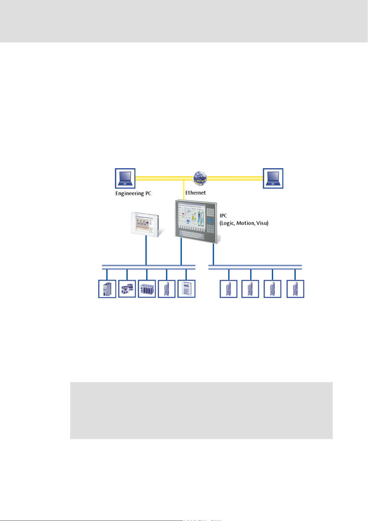
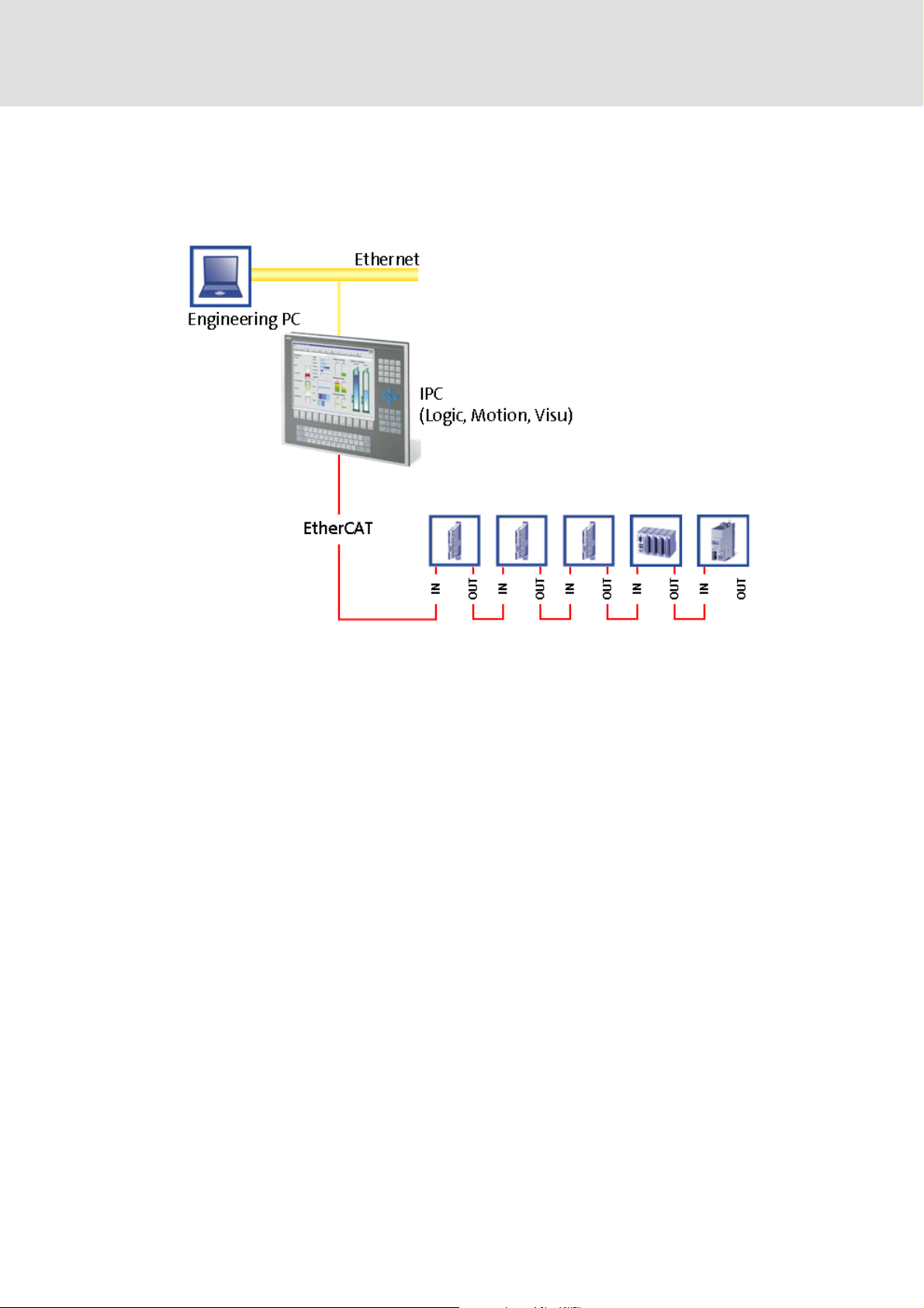
3 The "PC-based automation" system
Industrial PCs (IPCs) are increasingly finding their way into automation technology. With
their scaling characteristics and the possible combination of visualisation and control in
one device, industrial PCs offer clear advantages for many applications.
Lenze industrial PCs are available with the following software equipments:
Industrial PC as component (optional with operating system) without any further
software
Industrial PC as visualisation system
Industrial PC as control and visualisation system
The "PC-based automation" system allows the central control of Logic and Motion systems.
For this purpose, Lenze provides coordinated system components:
Industrial PCs as control and visualisation system
– The IPC is the central component of the PC-based automation which control the
Logic and Motion functionalities by means of the runtime software.
– The IPC communicates with the field devices via the fieldbus.
– The IPCs are available in different designs.
Note!
Moreover, the HMI series EL 1xx PLC belongs to the "PC based automation"
system. These devices differ considerably from the industrial PCs in performance
and various other details. However the devices of the HMI series EL 1xx PLC are
able to fulfil smaller control functions.
14 L DMS 3.1 EN 01/2011 TD17
Page 15

Control technology | EtherCAT communication manual
The "PC-based automation" system
Engineering tools for the Engineering PC
– The Engineering PC communicates with the IPC via Ethernet.
– The different engineering tools are used to configure and parameterise the system.
Fieldbuses
Field devices
DMS 3.1 EN 01/2011 TD17 L 15
Page 16

Control technology | EtherCAT communication manual
The Lenze control system with EtherCAT
Brief description of EtherCAT
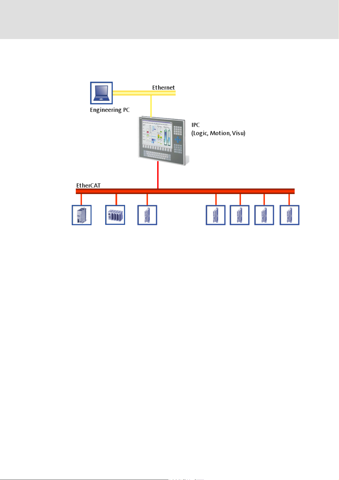
4 The Lenze control system with EtherCAT
Note!
For industrial PCs of the EL 1xx, EL x8xx, CS x8xx and CPC x8xx series in control
technology release 2.5, EtherCAT is not supported.
This chapter provides basic information about ...
the EtherCAT bus system;
the structure of the Lenze control system with the EtherCAT bus system;
the Lenze engineering tools required for commissioning.
the interaction of the components.
4.1 Brief description of EtherCAT
Tip!
More detailed information about EtherCAT can be found on the Internet website of
the EtherCAT Technology Group under:
www.EtherCAT.org
4.1.1 Features
EtherCAT is a high-performance bus system based on Ethernet.
Thanks to the integrated synchronisation mechanisms via "distributed clocks",
EtherCAT offers excellent real-time characteristics.
Synchronisation with "Distributed clocks"
EtherCAT provides a higher bandwidth compared to CANopen:
– This enables motion and logic applications to be operated by the same bus.
– The number of the nodes to be controlled is higher.
– The maximally possible bus length is longer.
EtherCAT can access all field devices via a common interface. Therefore, a division into
Logic fieldbus and MotionBus is not required.
( 36)
16 L DMS 3.1 EN 01/2011 TD17
Page 17
Control technology | EtherCAT communication manual
4.1.2 Structure of the EtherCAT bus system
Basic structure
The Lenze control system with EtherCAT
Brief description of EtherCAT
Physical structure
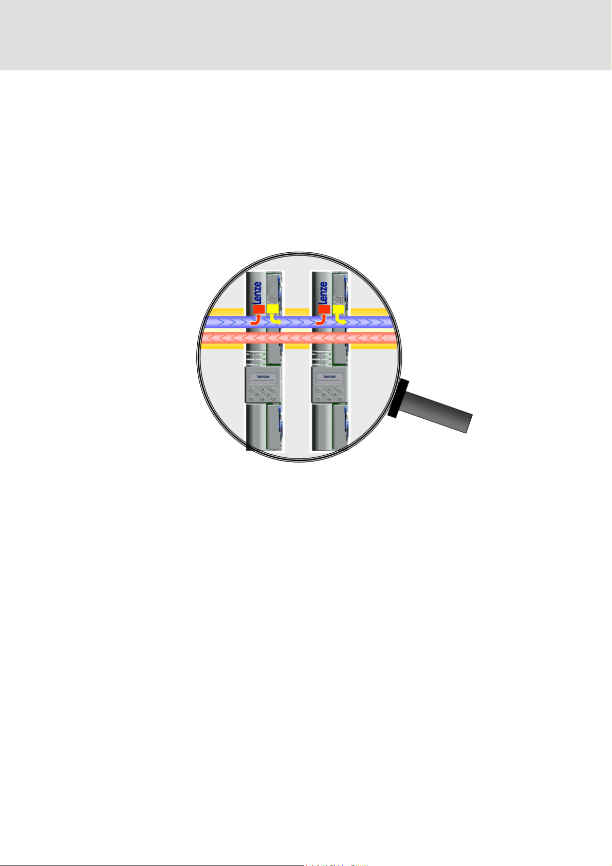
An EtherCAT master can communicate with one or more nodes ("slaves").
Internally, the EtherCAT bus has a ring topology. Since Ethernet cables are provided
with a going and a return conductor within one cable, for the installer the topology
seems to be a line. The last slave closes the ring.
Switches, hubs or other infrastructure components known from the Ethernet standard
must not be used because they impair the real-time performance.
DMS 3.1 EN 01/2011 TD17 L 17
Page 18
Control technology | EtherCAT communication manual
The Lenze control system with EtherCAT
Brief description of EtherCAT
4.1.3 Communication
Compared with the conventional Ethernet, the collision-free transfer of telegrams on the
bus makes EtherCAT a real-time capable bus system.
Communication is always initiated by the EtherCAT master, i.e. the industrial PC. A
telegram sent by the master passes through all EtherCAT slaves. The last slave of the
communication chain sends the telegram back to the EtherCAT master. On the way back,
the telegram is directly sent to the EtherCAT master, without being processed in the slaves.
With EtherCAT, telegram processing completely takes place on the hardware level. The
slaves take the data intended for them from the Ethernet frame and write their data back
to the Ethernet frame. Every datagram can be passed on with a minimum delay.
18 L DMS 3.1 EN 01/2011 TD17
Page 19
Control technology | EtherCAT communication manual
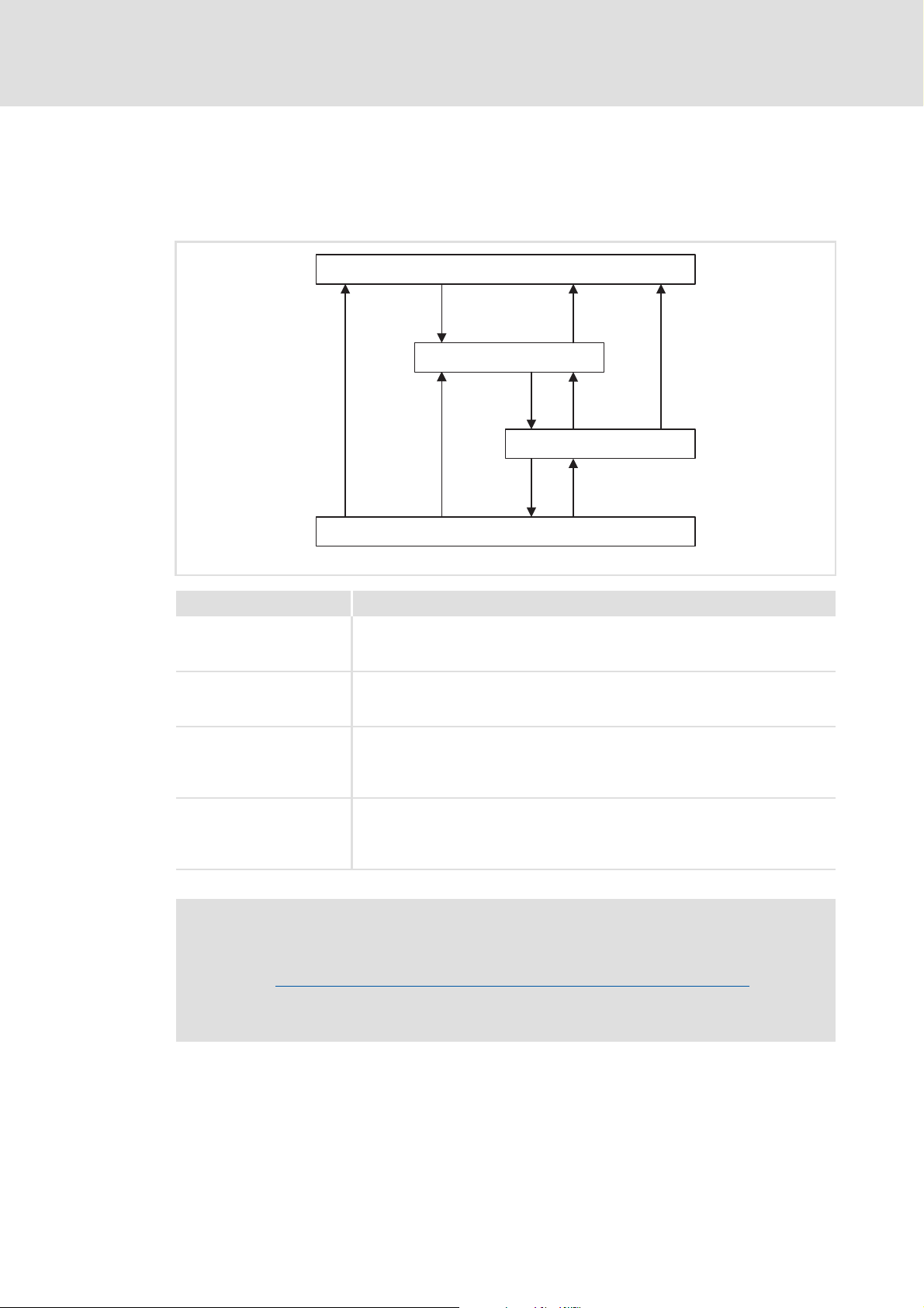
4.1.3.1 The EtherCAT state machine
Before communication via EtherCAT is possible, the bus runs through the EtherCAT state
machine during power-up. The following illustration shows the possible state change from
an EtherCAT slave's point of view:
The Lenze control system with EtherCAT
Brief description of EtherCAT
Init
Pre-Operational
Safe-Operational
Operational
Status Description
Init • Initialisation phase
• No SDO/PDO communication with the slaves
• Device can be detected by fieldbus scan
Pre-Operational • The fieldbus is active.
• SDO communication (mailbox communication) is possible.
• No PDO communication
Safe-Operational • SDO communication (mailbox communication) is possible.
• PDO communication:
–The input data is transmitted to the master and evaluated.
–The output data have the "Safe" state. It is not forwarded to the basic device.
Operational • Normal operation
–SDO communication
–PDO communication
–Fieldbus synchronisation has been successful (if used)
Note!
• Scanning of the EtherCAT fieldbus is possible in all states:
Determining the physical EtherCAT configuration (fieldbus scan)
• SDO communication via the EtherCAT fieldbus is only possible when at least
the Pre-Operational state has been reached.
E94AYCET009
( 47)
DMS 3.1 EN 01/2011 TD17 L 19
Page 20

Control technology | EtherCAT communication manual
The Lenze control system with EtherCAT
Brief description of EtherCAT
4.1.3.2 Addressing of the slaves
The EtherCAT system uses two types of addressing for the slaves:
Auto-increment addressing
Fixed-address addressing
The auto-increment addressing is used by the master during the initialisation phase of the
fieldbus. When the Pre-Operational state has been reached, the master uses the FixedAddress addressing.
Auto-increment addressing
The auto-increment addressing is based on the bus topology. Each slave can be addressed
by means of its physical position within the fieldbus.
Slave 1 = address 0
Slave 2 = address -1
Slave 3 = address -2 etc.
The master transmits a telegram to the slave address. Each slave increments the address
during the telegram cycle. A slave to which a telegram is addressed recognises the
telegram by means of the address 0.
A configuration example is given under:
Determining the physical EtherCAT configuration (fieldbus scan)
Fixed-address addressing
With the fixed-address addressing, the slaves are addressed via the station address
distributed by the master in the start-up phase.
In the EtherCAT bus topology in the »PLC Designer«, the first slave gets the address 1001,
the second slave the address 1002, etc. The EtherCAT addresses cannot be changed.
The EtherCAT address of the master is 0. Master objects with this address can also be
accessed via CoE.
Example
The first slave of a configuration obtains the following addresses:
0 by the auto-increment mode
( 47)
1001 by the fixed addressing mode (default address of the first slave in the »EtherCAT
Configurator«).
20 L DMS 3.1 EN 01/2011 TD17
Page 21

4.1.3.3 Working counter
Each EtherCAT datagram contains a working counter (WKC) which is incremented by each
slave after the data have been processed successfully.
In every cycle, the control unit compares the expected value of the working counter with
the value read back via the fieldbus. If the read-back value is lower than the expected value,
the telegram has not reached all addressed slaves. The control unit recognises this and
signals an error.
The working counter (WKC) can be used as a diagnostics option to check the processing of
the EtherCAT telegrams by the slaves.
Example
10 slaves read/write process data in the Operational status
Expected value of the WKC: 10
A cable break between the 8th and 9th slave causes the master to be unable to access
slave 9 and slave 10:
– Value of the restored WKC: 8
– An error response is initiated in the control.
Control technology | EtherCAT communication manual
The Lenze control system with EtherCAT
Brief description of EtherCAT
DMS 3.1 EN 01/2011 TD17 L 21
Page 22
Control technology | EtherCAT communication manual
The Lenze control system with EtherCAT
Required hardware components
4.2 Required hardware components
4.2.1 The industrial PC - the central component
The industrial PC is the central component in the EtherCAT bus system:
The industrial PC is the EtherCAT master.
The industrial PC acts as EtherCAT gateway to be able to access the field devices from
the engineering PC via Ethernet and EtherCAT.
The devices must be connected in a line. To ensure that the system operates properly,
the physical arrangement of the EtherCAT field devices must comply with the bus
topology created in the »EtherCAT Configurator«.
Each EtherCAT slave has two EtherCAT ports.
– In contrast to Ethernet, one port is assigned as input, the other one as output.
– Input (IN) and output (OUT) must not be reversed!
A bus termination at the last slave is not required since the bus system at the last slave
is terminated automatically.
22 L DMS 3.1 EN 01/2011 TD17
Page 23

4.2.2 Field devices
The Lenze control system supports the following EtherCAT-capable logic and motion
components:
Field devices EtherCAT bus
Industrial PCs EL x1xx PLC z -
Servo Drives 9400 1) HighLine z
Inverter Drives 8400 2) BaseLine z
I/O system 1000 EPM-Sxxx z
ECS servo system 3) ECSxE z
1) With EtherCAT E94AYCET communication module
2) With EtherCAT E84AYCET communication module
3) With EtherCAT EMF2192IB communication module
Control technology | EtherCAT communication manual
The Lenze control system with EtherCAT
Required hardware components
Logic Motion
EL x7xx zz
CS x7xx zz
CPC x7xx zz
Highline with CiA402 zz
PLC z
StateLine z
HighLine z
TopLine z
ECSxS (Speed & Torque) z
ECSxP (Posi & Shaft) z
ECSxM (Motion) z
ECSxA (Application) z
Field devices of other manufacturers can be integrated as logic nodes if they provide a
standard-compliant EtherCAT device description.
DMS 3.1 EN 01/2011 TD17 L 23
Page 24
Control technology | EtherCAT communication manual
The Lenze control system with EtherCAT
Required hardware components
4.2.3 EtherCAT product codes
The product codes serve to assign device descriptions to the corresponding devices. Device
descriptions can be installed via the device repository.
Importing missing field devices
The product codes are part of the device ID.
Structure of the device ID: <Manufacturer ID>_<Productcode><Revision number
Identification Meaning
Manufacturer ID Clear identification for the manufacturer, for Lenze devices: 0x3B
Product code Product code of the product range/the device
Revision number Revision number, consists of Major Revision (CANopen behaviour) and
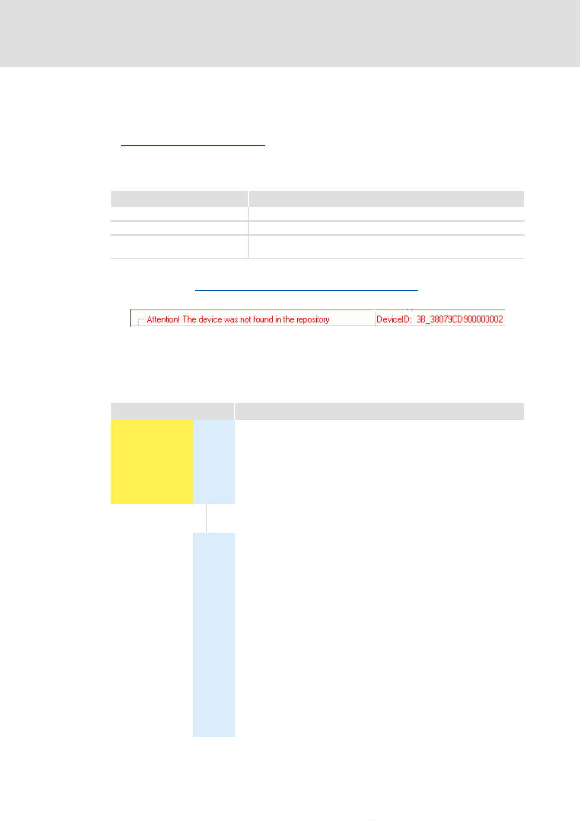
If, for instance, a device available at the fieldbus witout an installed device description is
detected during a Fieldbus scan with the »EtherCAT Configurator«
the device ID as hexidecimal value is displayed.
( 59)
Minor Revision (device version)
(59
hex
dec
( 47) , a message with
)
In the example, the device description for a Lenze Servo Drive 9400 HighLine, actuator –
speed, is not installed (0x38079CD9
= 940023001
hex
dec
).
Product codes for Servo Drives 9400
Product code [dec] Meaning
9 4 0 0 2 1 x x x Servo Drive 9400 in general
9 4 0 0 2 2 x x x Servo Drive 9400 StateLine
9 4 0 0 2 3 x x x Servo Drive 9400 HighLine
9 4 0 0 2 4 x x x Servo Drive 9400 TopLine
9 4 0 0 2 5 x x x Servo Drive 9400 PLC
9 4 0 0 2 6 x x x Servo Drive 9400 V/R (regenerative power supply module)
Applications:
0 0 0 Empty application
0 0 1 Actuating drive speed
0 0 2 Actuating drive torque
0 0 3 Electronic gearbox
0 0 4 Synchronism with mark synchronisation
0 0 5 Table positioning
0 0 6 Positioning sequence control
0 0 7 PLC application
000
89Reserved
...
...
9
Reserved
1 x x Reserved for device profiles
1 0 1 CiA402
2 x x Reserved for Lenze applications
2 0 1 Regenerative power supply module application
24 L DMS 3.1 EN 01/2011 TD17
Page 25

Control technology | EtherCAT communication manual
Product codes for Inverter Drives 8400
Product code [dec] Meaning
8 4 0 0 2 1 Inverter Drive 8400 BaseLine
8 4 0 0 2 2 Inverter Drive 8400 StateLine
8 4 0 0 2 3 Inverter Drive 8400 HighLine
8 4 0 0 2 4 Inverter Drive 8400 TopLine
Product codes for the I/O system 1000
The Lenze control system with EtherCAT
Required hardware components
Product code
[dec]
1 3 0 0 I/O system EPM-S130
Meaning
Product codes for the ECS servo system
Product code [dec] Meaning
2 1 9 2 0 7 0 0 ECSxA axis module "Application"
2 1 9 2 0 7 0 1 ECSxM axis module "Motion"
2 1 9 2 0 7 0 2 ECSxP axis module "Posi & Shaft"
2 1 9 2 0 7 0 3 ECSxS axis module "Speed & Torque"
2 1 9 2 0 7 1 1 ECSxE power supply module
DMS 3.1 EN 01/2011 TD17 L 25
Page 26
Control technology | EtherCAT communication manual
The Lenze control system with EtherCAT
Required hardware components
4.2.4 EtherCAT hardware for the industrial PC
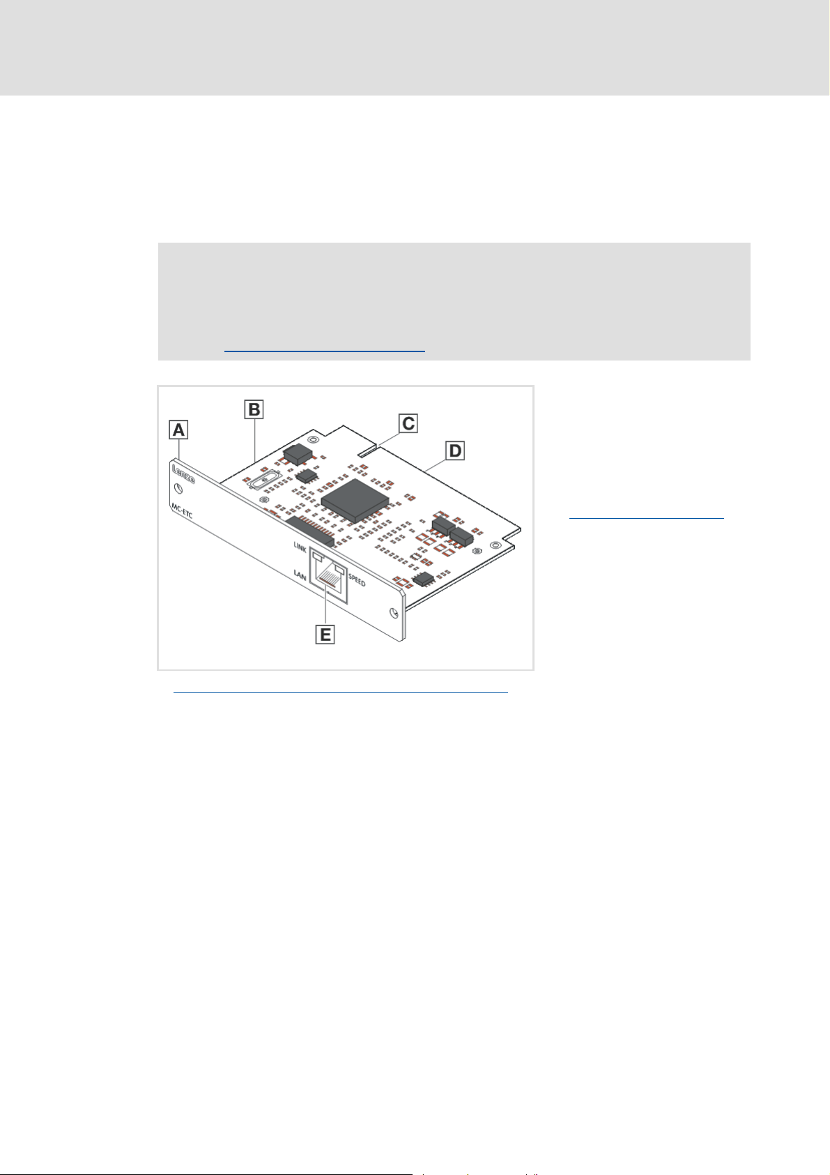
MC-ETC communication card
The MC-ETC communication card is a plug-in card for connecting an industrial PC to an
EtherCAT network.
Note!
In case of a correct connection to the field devices, the LEDs of the
communication card are lit.
Connection RJ45 socket / LEDs
( 34)
A Front panel
B Board
C Coding
D Connection
E EtherCAT connection
Connection RJ45 socket / LEDs
( 34)
MC-ETC-001
Technical data of the
MC-ETC communication card ( 34)
26 L DMS 3.1 EN 01/2011 TD17
Page 27
Control technology | EtherCAT communication manual
The Lenze control system with EtherCAT
Required hardware components
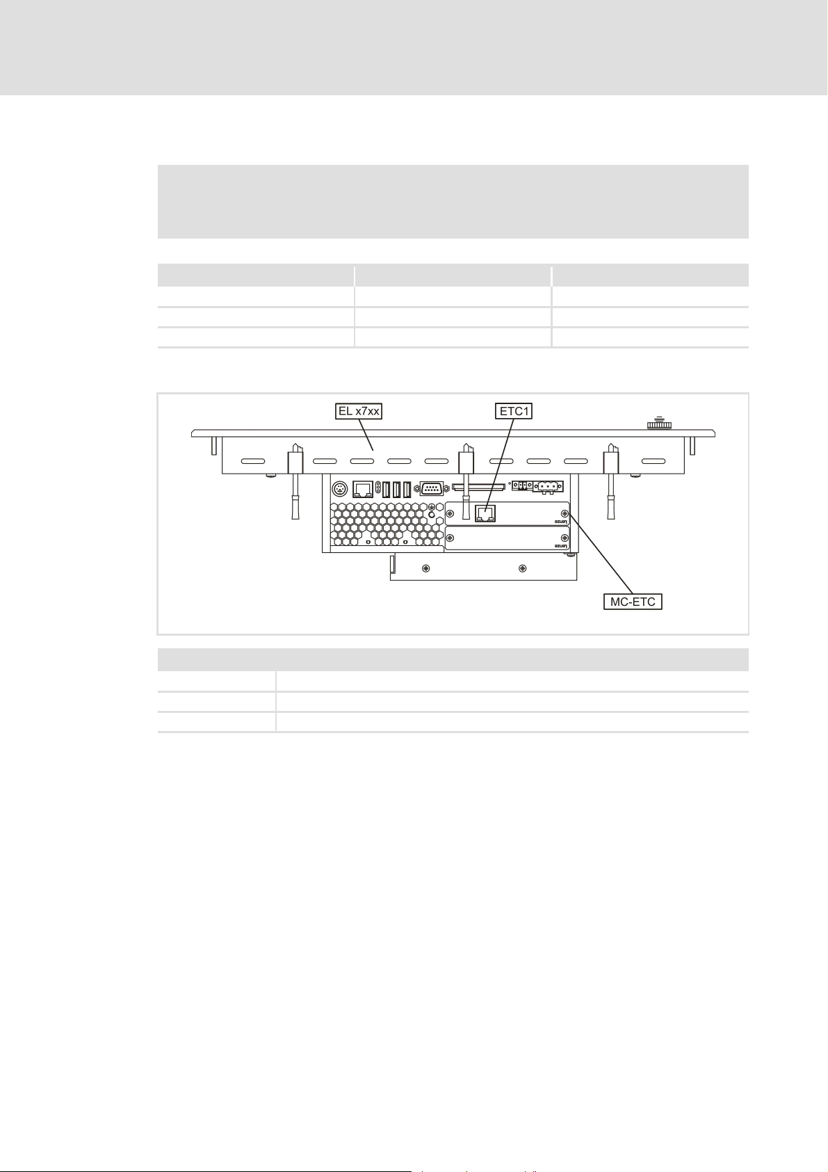
Possible applications
Note!
The industrial PC only supports one communication card MC-ETC!
Industrial PC Can be combined with CANopen Communication card for CANopen
EL x7xx yes MC-CAN2
CS x7xx no
CPC 2700 yes MC-CAN2
Example: Industrial PC EL x7xx with MC-ETC
Legend
EL x7xx Industrial PC of the EL x7xx series
ETC1 EtherCAT network connection
MC-ETC MC-ETC communication card
MC-ETC_ELx7xx
DMS 3.1 EN 01/2011 TD17 L 27
Page 28

Control technology | EtherCAT communication manual
The Lenze control system with EtherCAT
Required engineering tools
4.3 Required engineering tools
The engineering tools required for configuration and parameter setting are installed on
the engineering PC.
»Engineer«, »EtherCAT Configurator« and »PLC Designer« are engineering PC tools
which are independent of each other.
The EtherCAT bus, the industrial PC and the EtherCAT-capable field devices are
configured with the engineering tools highlighted in grey.
28 L DMS 3.1 EN 01/2011 TD17
Page 29
Control technology | EtherCAT communication manual
The Lenze control system with EtherCAT
Required engineering tools
Brief description of the engineering tools
L-force »Engineer«
With the »Engineer«, you can ...
parameterise, configure and diagnose ...
– Servo Drives 9400;
– Inverter Drives 8400;
– the I/O system 1000.
access the supported field devices via the gateway function of the industrial PC.
»Global Drive Control« ((GDC))
With (GDC) you can ...
parameterise, configure and diagnose controllers which are not supported by the
»Engineer« (e.g. devices of the ECS servo system).
access the supported field devices via the gateway function of the industrial PC (not
with PROFIBUS).
L-force »PLC Designer«
The »PLC Designer« is needed to ...
create the control program for the industrial PC;
transfer the PLC projects to the industrial PC.
DMS 3.1 EN 01/2011 TD17 L 29
Page 30
Control technology | EtherCAT communication manual
The Lenze control system with EtherCAT
Interaction of the components
4.4 Interaction of the components
4.4.1 The state machine of the Lenze control technology
In the Lenze control technology, the states of the PLC and the EtherCAT fieldbuses are
coupled. The PLC controls the fieldbus.
After switch-on the system automatically powers up if the following conditions are
fulfilled:
The IPC is provided with the configuration file for the EtherCAT master (master-XML
file), the contents of which corresponds to the real bus topology.
The IPC is provided with an executable PLC boot project.
The slaves at the fieldbus can be accessed.
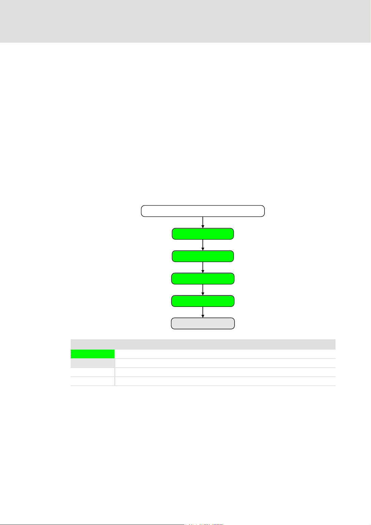
The following illustration shows the linkage of the states in the state machine of the Lenze
control technology when the conditions for the automatic acceleration of the system are
fulfilled (boot project with EtherCAT BusInterface and EtherCAT master configuration):
Switch on industrial PC and field devices
PLC: Original
EtherCAT: Unknown
PLC: Original
EtherCAT: Init
PLC: Original
EtherCAT: Pre-Operational
PLC: Running
EtherCAT: Safe-Operational
PLC: Running
EtherCAT: Operational
Legend
Transitional state, automatic change to next state
Stationary state, change to next state by external actions
PLC State of the PLC
EtherCAT State of the EtherCAT fieldbus
30 L DMS 3.1 EN 01/2011 TD17
Page 31

Control technology | EtherCAT communication manual
The Lenze control system with EtherCAT
Interaction of the components
Explanation of the transitions during system start
While a state is passed through, different tests are carried out (e.g. it is tested whether the
physical topology complies with the configuration). If the tests are successful, the system
automatically changes to the next state.
Status What happens? What is tested?
PLC EtherCAT
Origin Unknown The system starts. Is a master XML file available?
Origin Init EtherCAT is initialised.
Master XML file is imported.
Bus scan is executed
Origin Pre-Operational EtherCAT is active.
SDO communication is possible.
Running Safe-Operational The PLC program is being loaded.
The PLC is running.
The inputs are transferred, the
outputs are still in a safe state.
Running Operational The system is running.
Does the imported master XML
comply with the result of the bus
scan?
Is an executable boot project
available?
Are all inputs ok and initialised?
Detailed information about the possible bus states and the required commissioning steps
can be found here:
Commissioning of the system
( 42)
DMS 3.1 EN 01/2011 TD17 L 31
Page 32

Control technology | EtherCAT communication manual
The Lenze control system with EtherCAT
Interaction of the components
4.4.2 Communication between engineering PC and field devices
For commissioning of the field devices, an online connection is required between the
engineering PC and the corresponding field device. Depending on the state of the EtherCAT
bus, there are two options:
EtherCAT bus not in operation
EtherCAT bus in operation (gateway function) ( 33)
4.4.2.1 EtherCAT bus not in operation
You can communicate serially or via CANopen.
Condition:
Serial communication:
– You require the E94AZCUS diagnostic adapter.
– Field device and engineering PC (USB interface) must be connected via the diagnostic
adapter.
Communication via CANopen
– You required the EMF2177IB USB system bus adapter .
– Field devices and the engineering PC are connected via the system bus adapter -
either via a point-to-point connection or via the bus system.
Advantage:
Quick option of communication without commissioning of the EtherCAT bus.
( 32)
Disadvantage:
You require additional hardware.
Tip!
As soon as the fieldbus has been commissioned and at least achieved the PreOperational state, this communication path comes second. We recommend to
commission the EtherCAT bus as soon as possible to be able to use the gateway
function.
32 L DMS 3.1 EN 01/2011 TD17
Page 33

Control technology | EtherCAT communication manual
4.4.2.2 EtherCAT bus in operation (gateway function)
You directly communicate via EtherCAT and use the industrial PC as gateway.
Note!
A PLC program does not need to run to be able to use the gateway function.
The Lenze control system with EtherCAT
Interaction of the components
Condition
The bus configuration has been created using the »PLC Designer« and corresponds to
the hardware configuration.
The bus configuration has been loaded onto the industrial PC using the »PLC Designer«
and is active.
The fieldbus state is at least Pre-Operational.
Advantage:
You do not require any additional hardware.
The entire communication (process data, parameter data, and diagnostic data) are
transferred at the same time using a single bus connection.
DMS 3.1 EN 01/2011 TD17 L 33
Page 34
Control technology | EtherCAT communication manual
Technical data
General data of the EtherCAT bus
5 Technical data
5.1 General data of the EtherCAT bus
Field Values
Communication medium S/FTP (Screened Foiled Twisted Pair, ISO/IEC 11801 or EN 50173), CAT5e
Network topology Line
Number of nodes Max. 65535 ( in the entire network )
Max. cable length 100 m between two nodes
Baud rate 100 Mbit/s
EtherCAT module Direct mode
Communication profile CoE (CANopen over EtherCAT)
Synchronisation Distributed clocks
5.2 MC-ETC communication card
Field Values
Possible baud rate 100 Mbit/s
Type within the network Master
Connection RJ45 socket in accordance with EN 50173
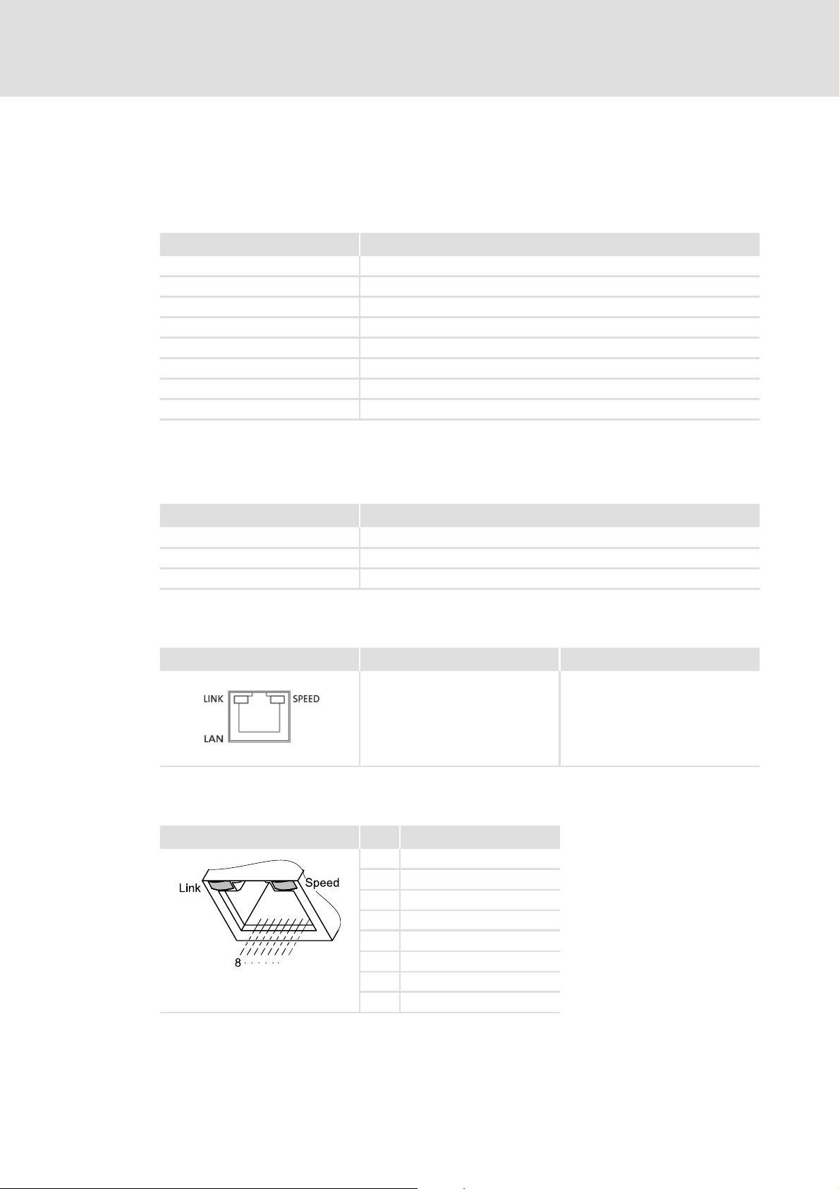
Connection RJ45 socket / LEDs
View Description Cable type
Pin assignment
RJ45 socket Pin Assignment
1
MC-ETH-001
E94YCEP018
EtherCAT connection
•LED "Link":
–On: connection ok
–Blinking: data exchange
• LED "Speed":
–Green: 100 MBit/s
1Tx +
2Tx -
3Rx +
4-
5-
6Rx -
7-
8-
•CAT5e S/FTP network cable
(recommended) in accordance
with ISO/IEC 11801 or EN 50173
• Cable length: max. 100 m
34 L DMS 3.1 EN 01/2011 TD17
Page 35

Control technology | EtherCAT communication manual
5.3 Communication times and drive-specific data
Field Values
User data per frame 1344 bytes
Process data words (PZD) for Servo
Drives 9400 HighLine
Parameter data (SDO) transfer Max. 128 bytes
Permissible EtherCAT cycle times 1 … 10 ms
Max. number of Servo Drives 9400
HighLine per frame
Total signal runtime for a cycle time
of 1ms
Drive
Control Drive
Runtime of the setpoints
Control
Drive
Runtime of the actual values
Drive
Control
Cross communication Not possible
Cycle synchronisation with locked
PLL (jitter)
max. 32 words (64 bytes)
User data of the frame (1344 bytes) divided by the process data length
resulting from setpoints and actual values of the drives:
• for 32 Tx/Rx bytes: 1344 bytes / 64 bytes = 21 drives
• for 16 Tx/Rx bytes: 1344 bytes / 32 bytes = 42 drives
5 ms
2 ms
3ms
+/-1 μs
Technical data
Communication times and drive-specific data
DMS 3.1 EN 01/2011 TD17 L 35
Page 36

Control technology | EtherCAT communication manual
Synchronisation with "Distributed clocks"
6 Synchronisation with "Distributed clocks"
The "Distributed clocks" (DC) function enables an exact time adjustment for applications
where several auxiliary axes carry out a coordinated movement at the same time. The data
is accepted synchronously with the PLC program. With the DC synchronisation, all slaves
are synchronised with a reference clock, called the "DC master".
Note!
• Motion applications always require DC synchronisation.
• DC synchronisation can also be used for Logic applications.
• Some slaves do not support the DC functionality.
– To be able to use the DC function, the first slave connected to the EtherCAT
master (IPC) must be DC-master-capable.
– In the arrangement of the slaves following then, DC-capable and non-DC-
capable devices can be mixed.
• The first EtherCAT node connected to the IPC must
provides the other EtherCAT nodes (including the IPC) with the exact time.
be the DC master which
The settings for the DC synchronisation are made with the »EtherCAT Configurator«.
Adjusting task cycle time and DC cycle time
( 38)
Setting the DC synchronisation with the »EtherCAT Configurator« ( 39)
36 L DMS 3.1 EN 01/2011 TD17
Page 37

Control technology | EtherCAT communication manual
6.1 Synchronous communication
The DC synchronisation provides for a phase-synchronous operation of master and slaves:
Within one bus cycle the setpoints are accepted and the actual values are detected in the
fieldbus at exactly the same time.
If the control (IPC) is synchronous to the distributed clocks, the data (actual values)
collected by the slave are assigned to the master at the end of the bus cycle and data from
the master (setpoints) are sent to the slaves for processing.
When the next DC synchronisation event occurs, the data are accepted.
Note!
State change and DC synchronisation for Servo Drives 9400 HighLine
During the state change from Operational to Pre-Operational, the DC
synchronisation is deactivated (C13883/C14883 = 0).
Synchronisation with "Distributed clocks"
Synchronous communication
In order to re-activate the sync pulses adjust your PLC program in the following
way:
• Call the function block ResetAxisGroup.
– In this way, the EtherCAT fieldbus is reinitialised.
– The DC synchronisation is active again (C13883/C14883 = 1).
DMS 3.1 EN 01/2011 TD17 L 37
Page 38
Control technology | EtherCAT communication manual
Synchronisation with "Distributed clocks"
Adjusting task cycle time and DC cycle time
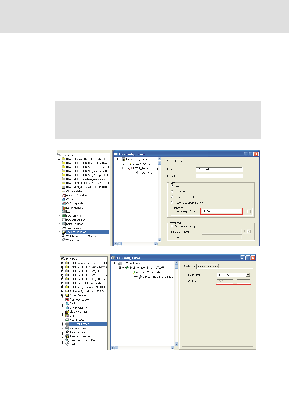
6.2 Adjusting task cycle time and DC cycle time
The industrial PC is the fieldbus master in the EtherCAT network. The clock pulse of the
EtherCAT bus system is determined by the cycle time of the task which is assigned to the
drives (slaves) in the »PLC Designer«.
The task settings in the »PLC Designer« only support integer millisecond cycles and the
smallest possible bus cycle is 1 millisecond. This cycle time can be defined via the task
configuration of the »PLC Designer«.
Note!
• The DC cycle time to be set in the »EtherCAT Configurator« must comply with
EtherCAT task cycle time set in the »PLC Designer«.
• Select the cycle times, according to the technical data, between 1 and 10 ms.
38 L DMS 3.1 EN 01/2011 TD17
Page 39
Control technology | EtherCAT communication manual
Synchronisation with "Distributed clocks"
Setting the DC synchronisation with the »EtherCAT Configurator«
6.3 Setting the DC synchronisation with the »EtherCAT Configurator«
Note!
The manual configuration of the slave DC features requires a detailed
knowledge of EtherCAT and the field device. Thus, DC settings should only be
made by experts.
A faulty configuration can cause maloperation and negative influences on the
system.
How to set the DC synchronisation:
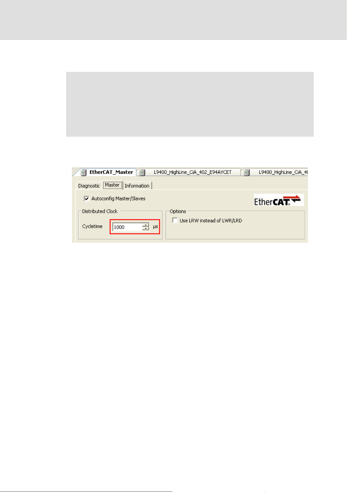
1. Set the Distributed clocks (DC) cycle time at the EtherCAT Master:
• The DC cycle time to be set in the »EtherCAT Configurator« must comply with
the EtherCAT task cycle time set in the »PLC Designer«.
• Select the cycle times, according to the technical data, between 1 and 10 ms.
• The (basic) cycle time set here is valid for all Logic and Motion nodes
synchronised by distributed clocks.
• For field devices with communication modules (e.g. Servo Drives 9400 or
Inverter Drives 8400), a synchronisation source must be selected via code
C01120. If the DC setting and the selection of the sync source differ from each
other (C01120 = MXI1 and "DC nused"), the devices cannot be set to the
Operational state.
•For Servo Drives 9400, code C13892/C14892 = 1 must be set (process data
mode = "deterministic mode").
DMS 3.1 EN 01/2011 TD17 L 39
Page 40
Control technology | EtherCAT communication manual
Synchronisation with "Distributed clocks"
Setting the DC synchronisation with the »EtherCAT Configurator«
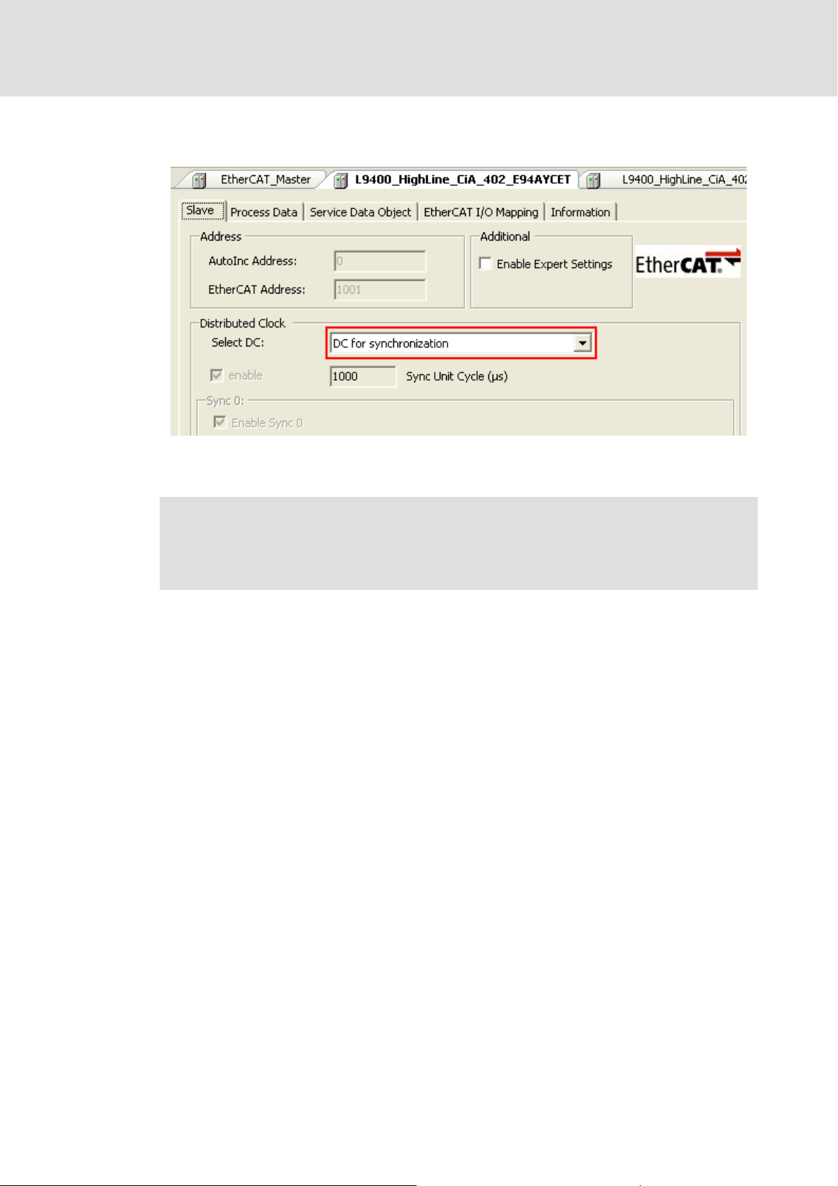
2. Activate the DC functionality for the first slave (DC master) connected to the bus
master (select "DC for synchronization"):
3. Also activate the DC functionality (select "DC for synchronization") for all other
slave devices which are to use the DC synchronisation.
Note!
Maintain all other basic DC settings for the slaves to ensure a correct DC
synchronisation.
40 L DMS 3.1 EN 01/2011 TD17
Page 41

Control technology | EtherCAT communication manual
6.4 Check of the DC synchronicity
The DC synchronicity can only be checked in the Operational bus state.
Synchronisation with "Distributed clocks"
Check of the DC synchronicity
You can check the DC synchronicity via the "ECAT DC: Status" parameter (code C1082/1
C1582/1
bEC_NOTIFY_DC_SLV_SYNC.
) or via the Notifications ( 120) bEC_NOTIFY_DC_STATUS and
/
DMS 3.1 EN 01/2011 TD17 L 41
Page 42

Control technology | EtherCAT communication manual
Commissioning of the system
7 Commissioning of the system
This chapter provides information about how to commission the Lenze control system
with EtherCAT.
Commissioning of the system requires the following Lenze engineering tools:
»EtherCAT Configurator«
»PLC Designer«
»Engineer«
An overview of the commissioning steps is given in the next section Overview of
commissioning steps ( 43). Follow the instructions of these sections step by step in order
to commission your system.
At the end of this chapter you will find a chart showing a Detailed overview of the
commissioning steps ( 90) with regard to the different Lenze engineering tools.
42 L DMS 3.1 EN 01/2011 TD17
Page 43

Control technology | EtherCAT communication manual
7.1 Overview of commissioning steps
Commissioning of the system
Overview of commissioning steps
DMS 3.1 EN 01/2011 TD17 L 43
Page 44
Control technology | EtherCAT communication manual
Commissioning of the system
Overview of commissioning steps
The main commissioning steps are listed in the following table:
Step Activity Software used
1. Installing field devices
2. Creating a project folder
3. Fieldbus scan with the »EtherCAT Configurator«
Fieldbus scan with the »scandf« command line tool
4. Inserting devices available on the fieldbus into the »EtherCAT
Configurator« project ( 55)
Creating the configuration in the »EtherCAT Configurator«
5. Export of EtherCAT configuration
6. Configuration in the »Engineer«
8. Configuration in the »PLC Designer«
9. Loading the control configuration onto the IPC
10. Loading the master configuration onto the EtherCAT master
11. Loading and starting the PLC program
( 45)
( 46)
( 47) »EtherCAT Configurator«
( 51) Command line tool »scandf«
( 56)
( 67) »EtherCAT Configurator«
( 54) »Engineer«
( 68) »PLC Designer«
( 78) »PLC Designer«
( 79) »PLC Designer«
( 79) »PLC Designer«
»EtherCAT Configurator«
44 L DMS 3.1 EN 01/2011 TD17
Page 45

Control technology | EtherCAT communication manual
7.2 Detailed commissioning steps
In the following sections, the individual commissioning steps are described.
More detailed information about how to work with the Lenze engineering tools
can be found in the corresponding manuals and online helps.
7.2.1 Planning the bus topology
Before you start to set up an EtherCAT network, first create a plan of your EtherCAT bus.
Brief description of EtherCAT
How to plan the bus topology for your configuration:
1. Create an overview of the planned EtherCAT network with all field devices to be
integrated.
Commissioning of the system
Detailed commissioning steps
( 16)
2. Start with the industrial PC.
3. Add the other field devices below.
4. You have to distinguish between the following two cases:
• Operation without synchronisation via distributed clocks:
DC synchronisation is not required if exclusively Logic field devices are to be
operated on the network. The sequence of the field device interface connections
on the bus can freely be selected.
• Operation with synchronisation via distributed clocks:
DC synchronisation is required if Motion and Logic field devices are to be
operated on the network. The first node connected to the control IPC must be
capable of being a DC master. The sequence of the other Logic and Motion field
device interface connections can freely be selected.
7.2.2 Installing field devices
For the installation of a field device, follow the mounting instructions for the respective
device.
Note!
• The EtherCAT interfaces of all devices must be wired according to the planned
topology. The inputs (IN) and outputs (OUT) must not be reversed because
otherwise the topology changes.
Communication
• The structure of the EtherCAT configuration must be identical with the order
of the devices in the »EtherCAT Configurator«.
• The master automatically assigns the node addresses to the slaves.
Therefore, a manual address assignment is not required.
DMS 3.1 EN 01/2011 TD17 L 45
( 18).
Page 46

Control technology | EtherCAT communication manual
Commissioning of the system
Detailed commissioning steps
7.2.3 Creating a project folder
Create a project folder on the engineering PC.
Use this project folder to store the below data generated in the different project
configuration steps:
The project file created in the »EtherCAT Configurator«
The configuration files exported from the »EtherCAT Configurator«:
– ECAT_PLC_CFG_1.XML
– ECAT_MASTER_1.XML
The project data created in the »Engineer«
The project file created in the »PLC Designer«
Tip!
Create a separate project folder for every EtherCAT configuration and store the
project and configuration files in this folder.
46 L DMS 3.1 EN 01/2011 TD17
Page 47

Control technology | EtherCAT communication manual
Commissioning of the system
Detailed commissioning steps
7.2.4 Determining the physical EtherCAT configuration (fieldbus scan)
You can execute a fieldbus scan with the »EtherCAT Configurator« on the IPC in order to
check the physical EtherCAT configuration. Alternatively, the command line tool »scandf«
( 51) is also available on the IPC.
Note!
• Scanning of the EtherCAT fieldbus is also possible without an appropriate
EtherCAT configuration.
• Communication to field devices via the EtherCAT fieldbus is only possible if at
least the Pre-Operational state has been reached.
7.2.4.1 Fieldbus scan with the »EtherCAT Configurator«
The »EtherCAT Configurator« offers the possibility to execute an online search for devices
which are connected to the EtherCAT fieldbus.
In order to search for devices you must first establish an online connection of the
»EtherCAT Configurator« with the industrial PC.
How to execute a fieldbus scan with the »EtherCAT Configurator«:
1. Enter the IP address of the industrial PC:
• Select the L-force Controller by double-clicking in the device tree:
• Enter the IP address of the industrial PC which should serve as control unit of the
configuration into the Online access configuration dialog box in the Master
configuration area:
DMS 3.1 EN 01/2011 TD17 L 47
Page 48
Control technology | EtherCAT communication manual
Commissioning of the system
Detailed commissioning steps
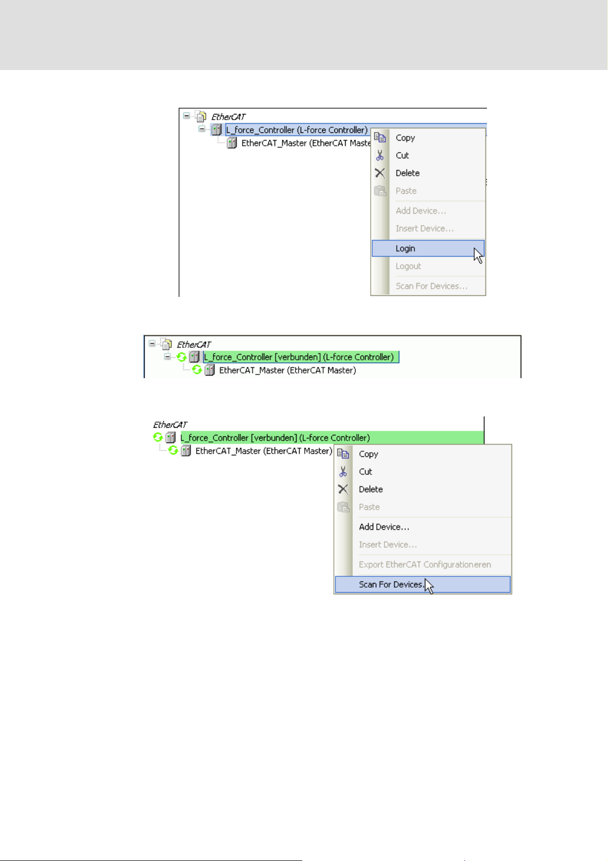
2. Execute the Login command in the context menu of the L-force Controller:
After a successful login, the L-force Controller (the industrial PC) is connected to the
engineering PC:
3. After a successful login, execute the Start Search command in the context menu of
the L-force Controller :
48 L DMS 3.1 EN 01/2011 TD17
Page 49

Control technology | EtherCAT communication manual
Commissioning of the system
Detailed commissioning steps
The »EtherCAT Configurator« determines the EtherCAT nodes available at the
fieldbus. In the Start Search dialog box, the devices are listed according to the
physical order at the fieldbus:
Further information on the Start Search dialog box can be found here:
Inserting devices available on the fieldbus into the »EtherCAT Configurator«
project ( 55)
DMS 3.1 EN 01/2011 TD17 L 49
Page 50

Control technology | EtherCAT communication manual
Commissioning of the system
Detailed commissioning steps
Missing device descriptions
If a device available at the fieldbus is not present in the device repository, an error message
within the Start Search dialog box will inform you about it:
The device cannot be interpolated into the project as the corresponding device
description has not been installed.
In order to install the device in the device repository, the corresponding device
description file from the manufacturer is required. The device identification (device ID)
can be helpful to identify the device (see also EtherCAT product codes
( 24)).
Importing missing field devices
( 59)
50 L DMS 3.1 EN 01/2011 TD17
Page 51
Control technology | EtherCAT communication manual
7.2.4.2 Fieldbus scan with the »scandf« command line tool
Fieldbus scanning command
Command: scanfd <interface> /option
The interface for the EtherCAT slaves to be scanned on the fieldbus is called ECAT.
Option Output on the console
/i Determine available interfaces
/t Display device information for every network node.
/f Display additional device parameters for every device if available.
/n Suppress prompt before execution of the fieldbus scan.
How to carry out a fieldbus scan:
1. Establish a Telnet connection to the IPC.
Commissioning of the system
Detailed commissioning steps
More detailed information is provided in the documentation for the IPC.
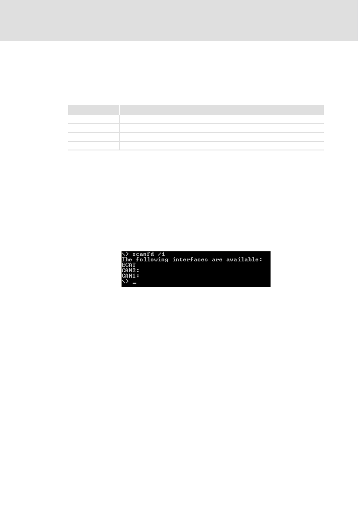
2. Call scanfd.exe via the command line box of the IPC to scan the fieldbus.
3. Determine the available interfaces of the IPC:
• Enter scanfd /i.
Output example:
The fieldbus scanner displays the available interfaces:
• ECAT for the EtherCAT-capable field devices,
• CAN1 and CAN2 for the CAN field devices.
DMS 3.1 EN 01/2011 TD17 L 51
Page 52

Control technology | EtherCAT communication manual
Commissioning of the system
Detailed commissioning steps
4. Determine the field devices physically available at the ECAT
interface:
• scanfd ecat /t /f /n
Output example:
After executing the scanfd.exe file, the console displays the result of the fieldbus
scan. The first output line contains the number (x) of slaves found on the fieldbus:
x devices at interface ´ecat´!
The further output lines provide informationen on each slave:
52 L DMS 3.1 EN 01/2011 TD17
Page 53

Control technology | EtherCAT communication manual
Commissioning of the system
Detailed commissioning steps
Information about the field devices
The individual slaves are generally listed according to the auto-increment addressing
scheme in their physically order.
The first slave connected to the master has the node address 0. The second slave has
the negative node address -1. The other slaves have negative node addresses (-n)
corresponding to their positions on the fieldbus.
Information Function
DeviceID Node address of the slave:
• Display of the auto-increment address.
• The first slave has the node address 0.
Vendor Name of the manufacturer
ProductCode Product designation in hexadecimal format
(see also EtherCAT product codes
Examples:
#x38079cd9: Lenze Servo Drive 9400 HighLine TA speed acuating drive
#x38079d3d: Lenze Servo Drive 9400 HighLine CiA402
RevisionNumber Version number in hexadecimal format
SerialNumber Serial number in hexadecimal format
( 24))
Troubleshooting
If the fieldbus scan does not find any field devices at the selected interface, the following
error message appears:
How to check the physical configuration:
1. Analyse the messages in the Logbook of the IPC
( 142)
2. Check the wiring.
( 140). IPC logbook messages
DMS 3.1 EN 01/2011 TD17 L 53
Page 54

Control technology | EtherCAT communication manual
Commissioning of the system
Detailed commissioning steps
7.2.5 Configuration in the »Engineer«
The »Engineer« is used to configure and parameterise the Lenze field devices connected to
the EtherCAT bus.
Note!
PDO mapping settings
The mapping required for a cross communication must be created in the
»EtherCAT Configurator«/»PLC Designer«.
During start-up of the PLC, the complete configuration/PDO mapping is written
into the EtherCAT slaves. Mapping entries, e.g. from the »Engineer«, are not
overwritten.
Executing PDO mapping
Editing the EtherCAT I/O image ( 66)
( 65)
How to configure the drives in the »Engineer«:
1. Create a new »Engineer« project or open an already existing project.
2. Insert the Lenze field devices in the device tree and select the hardware
configuration of the axes.
For Servo Drives 9400:
• Select inverter.
• Select motor.
• Select modules.
3. Assign an application to the field devices and set the drive parameters.
4. Save the »Engineer« project to the project folder.
54 L DMS 3.1 EN 01/2011 TD17
Page 55
Control technology | EtherCAT communication manual
Commissioning of the system
Detailed commissioning steps
7.2.6 Inserting devices available on the fieldbus into the »EtherCAT Configurator« project
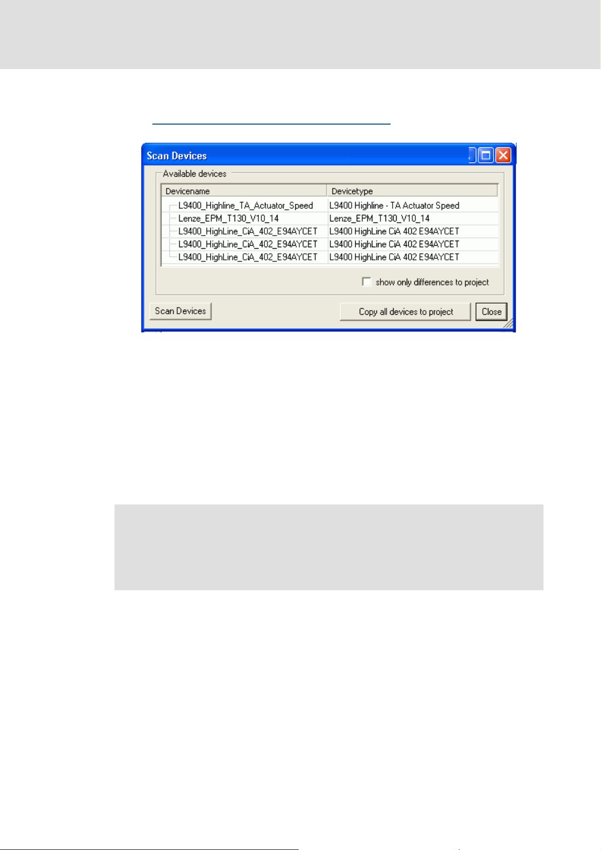
After a Fieldbus scan with the »EtherCAT Configurator«
listed according to their physical order at the fieldbus in the Start Search dialog box:
Here you can...
assign individual unique device names in the Device name column. Observe the
IEC 61131 syntax (no spaces and leading digits in variable names)!
select individual devices in the Device name column and copy them into your
»EtherCAT Configurator« project:
– Activate the Copy into project button.
–The Copy into project button will only appear if one or more devices are selected.
( 47) the EtherCAT nodes are
copy all available devices into your »EtherCAT Configurator« project.
– Activate the Copy all devices into project button.
Note!
We recommend to copy all devices into the project.
After pasting you must check if the order of the devices in the project
corresponds to the physical order in the network.
( 55)
DMS 3.1 EN 01/2011 TD17 L 55
Page 56

Control technology | EtherCAT communication manual
Commissioning of the system
Detailed commissioning steps
7.2.7 Creating the configuration in the »EtherCAT Configurator«
The »EtherCAT Configurator« is used to set up the EtherCAT configuration. During this
process, the ECAT_PLC_CFG_1.XML and ECAT_MASTER_1.XML configuration files are
created.
These files...
illustrate the physical structure of the EtherCAT configuration;
contain synchronisation settings, SoftMotion parameter values (only of SoftMotion
nodes) and the variable mapping of the EtherCAT nodes.
At a later time, you have to
import the ECAT_PLC_CFG_1.XML file into the control configuration using the »PLC
Designer«.
write the ECAT_MASTER_1.XML file to the IPC.
Note!
• The order of the EtherCAT slaves in the device tree must correspond to the
physical order of the EtherCAT configuration.
• In order that the system works properly, end terminals must not be used
when setting up the system configuration in the device tree.
• For the integration of external devices, the »EtherCAT Configurator« only
Observe the following conditions before you lay out a topology in the »Engineer«:
SoftMotion operation is only possible with Servo Drives 9400 Highline CiA402.
The »EtherCAT Configurator« supports Lenze EtherCAT slaves and EtherCAT devices of
other manufacturers. The integration of third-party devices requires the respective
manufacturer's device descriptions.
Importing missing field devices
supports device descriptions meeting the standards.
• Select the cycle times, according to the technical data, from 1 ... 10 ms. The
cycle times are carried out by the configurations in the »EtherCAT
Configurator« and »PLC Designer«.
( 59)
56 L DMS 3.1 EN 01/2011 TD17
Page 57

Control technology | EtherCAT communication manual
7.2.7.1 Setting up the EtherCAT configuration in the device tree
Note!
The order of the devices in the »EtherCAT Configurator« must correspond with
the physical structure of the EtherCAT configuration.
How to set up the EtherCAT configuration in the device tree:
1. Create a new project in the »EtherCAT Configurator«:
• Menu command: FileNew Project.
2. Map the physical configuration in the device tree:
• Add the individual field devices to the EtherCAT_Master of the configuration:
Execute the Add Device command of the EtherCAT_Master context menu:
Commissioning of the system
Detailed commissioning steps
DMS 3.1 EN 01/2011 TD17 L 57
Page 58

Control technology | EtherCAT communication manual
Commissioning of the system
Detailed commissioning steps
3. Select the device in the selection list of the Add Device dialog box:
4. Enter the device name in the Name input field (example: X_axis_vertical),
• Click the Add Device button.
5. Add more slaves of the configuration to the device tree:
• Select the device to which a slave is to be added. Select the Insert Device
command from the device context menu.
• Devices missing in the selection list can be added by importing the
corresponding device description file.
Importing missing field devices
6. Close the dialog box by clicking the Close button.
( 59)
58 L DMS 3.1 EN 01/2011 TD17
Page 59

Control technology | EtherCAT communication manual
7.2.7.2 Importing missing field devices
Additional device descriptions can be installed via the device repository.
The device repository manages the device description files stored locally on the system.
How to import additional device descriptions:
1. Open the device repository with the ToolsDevice Repository menu command:
Commissioning of the system
Detailed commissioning steps
2. Click the Install button.
3. Select the device description file(s) to be imported from the Installed device
descriptions dialog box appearing now.
4. Finally, click the Open button to execute the file import command.
• A progress bar indicates the installation process.
DMS 3.1 EN 01/2011 TD17 L 59
Page 60

Control technology | EtherCAT communication manual
Commissioning of the system
Detailed commissioning steps
7.2.7.3 Setting up a DC synchronisation
Note!
The manual configuration of the slave DC features requires a detailed
knowledge of EtherCAT and the field device. Thus, DC settings should only be
made by experts.
A faulty configuration can cause maloperation and negative influences on the
system.
Motion applications always require
DC synchronisation can also be used for Logic applications.
To be able to use the DC function, the first slave connected to the EtherCAT master (IPC)
must be DC-master-capable.
The first EtherCAT node connected to the IPC is the DC master which provides the other
bus nodes (including the IPC) with the exact time.
In the arrangement of the slaves following then, DC-capable and non-DC-capable
devices can be mixed.
For field devices with communication modules (e.g. Servo Drives 9400 or Inverter
Drives 8400), a synchronisation source must be selected via code C01120. If the DC
setting and the selection of the sync source differ from each other (C01120 = MXI1 and
"DC nused"), the devices cannot be set to the Operational state.
For Servo Drives 9400, code C13892/C14892 = 1 must be set (process data mode =
"deterministic mode").
DC synchronisation.
60 L DMS 3.1 EN 01/2011 TD17
Page 61

Control technology | EtherCAT communication manual
Commissioning of the system
Detailed commissioning steps
How to set the DC synchronisation:
1. Configure the synchronisation of the EtherCAT slaves via distributed clocks (DC).
• Set the Distributed clocks (DC) cycle time at the EtherCAT Master:
• The DC cycle time to be set in the »EtherCAT Configurator« must be identical to
the EtherCAT task cycle time set in the »PLC Designer«.
• Select the cycle times, according to the technical data, between 1 and 10 ms.
• The (basic) cycle time set here is valid for all Logic and Motion nodes
synchronised by distributed clocks.
DMS 3.1 EN 01/2011 TD17 L 61
Page 62

Control technology | EtherCAT communication manual
Commissioning of the system
Detailed commissioning steps
2. Activate the DC functionality for the first slave (DC master) connected to the bus
master (select "DC for synchronization"):
3. Also activate the DC functionality (select "DC for synchronization") for all other
slave devices which are to use the DC synchronisation.
Note!
Maintain all other basic DC settings for the slaves to ensure a correct DC
synchronisation.
62 L DMS 3.1 EN 01/2011 TD17
Page 63

Control technology | EtherCAT communication manual
7.2.7.4 Set SoftMotion parameters.
Note!
The SoftMotion Drive: Basic tab is only available for Lenze EtherCAT slaves using
the CiA402 application (SM_Drives).
The settings depend on the application:
Commissioning of the system
Detailed commissioning steps
Input fields Function/description
Axis type and limits
• Virtual mode Activate virtual mode for the configuration to be selected.
• Rotary Select configuration for rotary axis.
• Linear Select configuration for linear axis.
Modulo settings (only for rotary operation)
• Modulo value Define SoftMotion units for rotary operation.
(With the value 360.0, the drive would carry out exactly one mechanical
revolution.)
Software limits (only for linear operation)
• Activated Activate software limit switches.
• Negative Define value for negative software limit switch.
• Positive Define value for positive software limit switch.
Limits for CNC (limits are only effective for CNC operation.)
• Velocity Define maximum (setpoint) velocity of the axis.
• Acceleration Define maximum acceleration.
• Deceleration Define maximum deceleration.
Velocity ramp type
• Trapezoid Trapezium
2
•sin
• Parabolic Parabola
• Jerk Value for jerk (only for the ramp types "sin
Sine curve
2
" and "parabolic")
A detailed description of the velocity ramp types can be found in the
documentation/online help for the »PLC Designer« (SoftMotion).
DMS 3.1 EN 01/2011 TD17 L 63
Page 64

Control technology | EtherCAT communication manual
Commissioning of the system
Detailed commissioning steps
Not all parameters required for operating a Motion drive acan be set automatically via the
control.
Set the following parameters for the Servo Drives 9400 HighLine CiA402 manually via the
»Engineer« or the »Global Drive Control«:
Homing mode (C02640, to be set machine-dependent)
Touch-probe interface (to be set machine-dependent)
Control of a holding brake (0x60FB/2 | Brake control)
– Depending on the setting of this parameter, the holding brake is applied for a short
time after the conclusion of the home position path. In order to avoid this, set bit 2
in this parameter (disable stop => does not apply the brake in standstill).
64 L DMS 3.1 EN 01/2011 TD17
Page 65
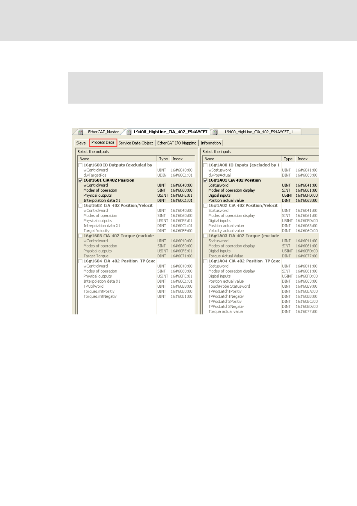
Control technology | EtherCAT communication manual
7.2.7.5 Executing PDO mapping
Note!
The PDO mapping must only be set for the Servo Drives 9400 HighLine CiA402.
Set the PDO mapping via the process data tab (standard setting for Servo Drives 9400
HighLine CiA402):
Commissioning of the system
Detailed commissioning steps
The settings for the outputs and inputs must be identical.
In order to change the setting, you must first deselect the current setting. After that you
can freely select the wanted setting.
DMS 3.1 EN 01/2011 TD17 L 65
Page 66
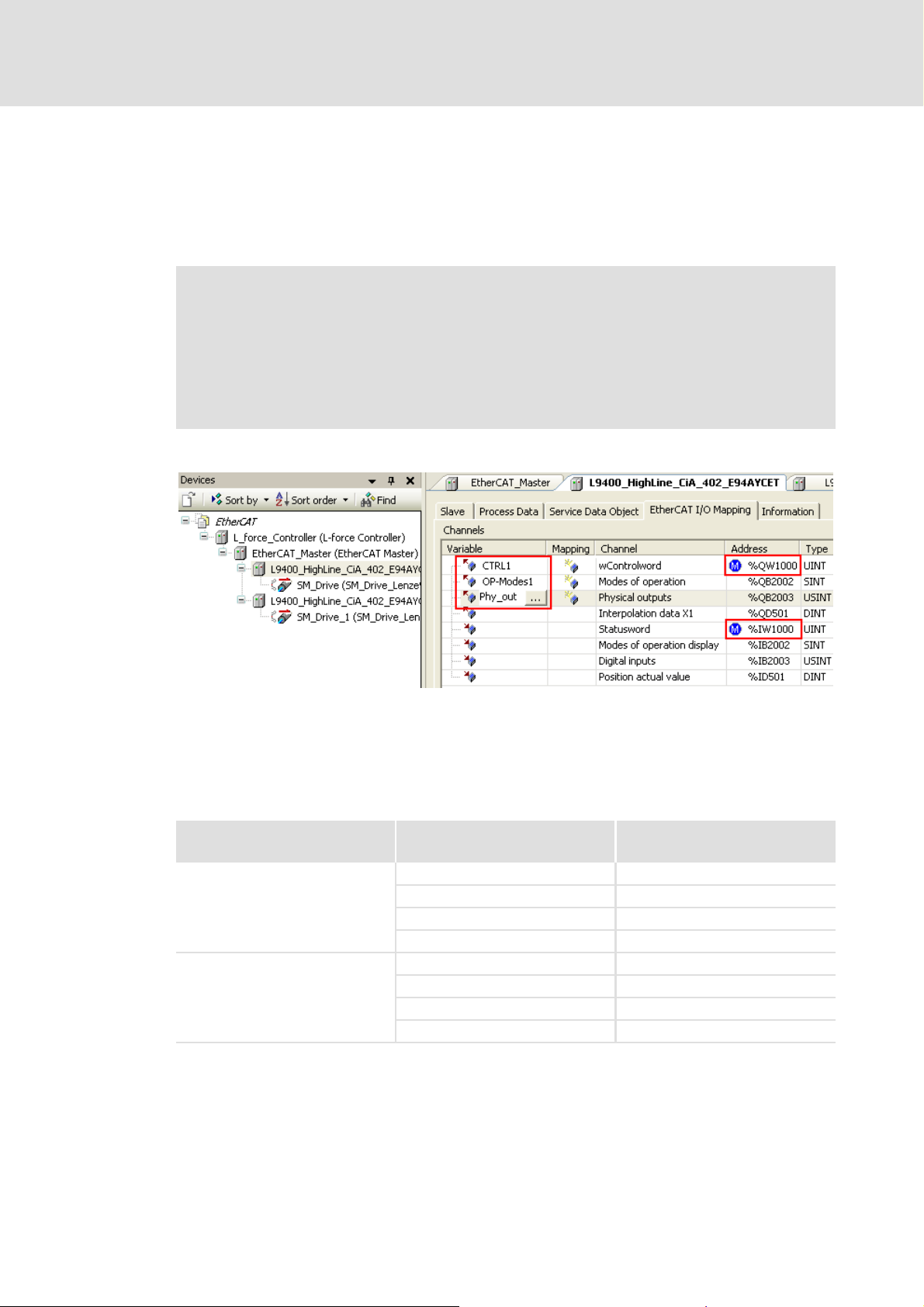
Control technology | EtherCAT communication manual
Commissioning of the system
Detailed commissioning steps
7.2.7.6 Editing the EtherCAT I/O image
Assign non-ambiguous variable names to the input and output objects according to
IEC 61131 syntax (no blanks and leading digits in the variable name). After the import
of the EtherCAT configuration into the »PLC Designer« control configuration,
corresponding system variables are available for the PLC program.
Note!
• Always use the system variables within the PLC program in order to access the
input and output objects or assign values to them.
• When copying a device in the »EtherCAT Configurator«, you must rename the
variables for the device copy, otherwise there will be a compiler error during
the compilation in the »PLC Designer«.
By double-clicking the corresponding fields, you can make the adjustments:
In the example, variable names have been assigned to the first three output objects.
Moreover, an offset of ’1000’ has been entered for the first output object (%QW...) and the
first input object (%IW...).
The »EtherCAT Configurator« does not work with byte addresses. The objects are
addressed with the byte address in the control configuration:
Objects Addresses in the
»EtherCAT Configurator«
Output objects %QX1000.0 %QB1000
%QB1000 %QB1000
%QW1000 %QB500
%QD1000 %QB250
Input objects %IX1000.0 %IB1000
%IB1000 %IB1000
%IW1000 %IB500
%ID1000 %IB250
Byte addresses
66 L DMS 3.1 EN 01/2011 TD17
Page 67
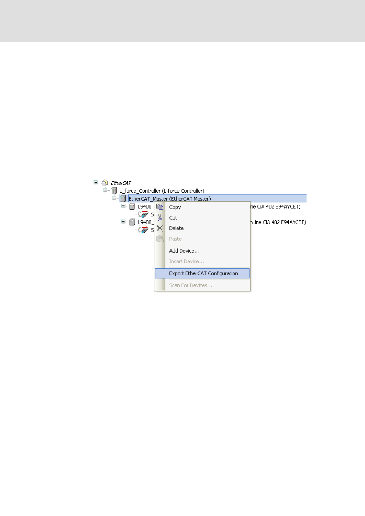
Control technology | EtherCAT communication manual
7.2.7.7 Export of EtherCAT configuration
First save your project with the menu command FileSave project to in the project folder
before you export the EtherCAT configuration.
During the export of the EtherCAT configuration, the configuration files
ECAT_PLC_CFG_1.XML and ECAT_MASTER_1.XML created.
At a later time, you have to
import the ECAT_PLC_CFG_1.XML file into the control configuration using the »PLC
Designer«.
write the ECAT_MASTER_1.XML file for the EtherCAT master stack to the IPC.
How to export the EtherCAT configuration files:
1. Select Export EtherCAT Configuration from the context menu of the master:
Commissioning of the system
Detailed commissioning steps
2. A directory tree appears. Select the prepared project folder for storing.
3. Confirm the selection by clicking the OK button.
The configuration files ECAT_PLC_CFG_1.XML and ECAT_MASTER_1.XML is now
saved to the project folder.
DMS 3.1 EN 01/2011 TD17 L 67
Page 68

Control technology | EtherCAT communication manual
Commissioning of the system
Detailed commissioning steps
7.2.8 Configuration in the »PLC Designer«
The »PLC Designer« serves to illustrate the field device topology in the control
configuration.
Tip!
Nodes at other fieldbus systems can be configured in the »PLC Designer«.
EtherCAT with CANopen or PROFIBUS
7.2.8.1 Set-up of control configuration
How to set up the control configuration in the »PLC Designer«:
1. Create a new »PLC Designer« project:
• Menu command: FileNew
2. Select the suitable target system from the Target Settings dialog box:
• L-force_Logic_x700_Vx.xx.xx for Logic target systems
• L-force_Motion_x700_Vx.xx.xx for pure Motion target systems or Motion- and
Logic target systems
( 91)
EtherCAT with CANopen or PROFIBUS
3. Confirm the configuration of the target system setting by clicking the OK button.
68 L DMS 3.1 EN 01/2011 TD17
( 91)
Page 69

4. Create a block:
Note!
The program organisation unit must contain at least one instruction to function
properly.
Control technology | EtherCAT communication manual
Commissioning of the system
Detailed commissioning steps
DMS 3.1 EN 01/2011 TD17 L 69
Page 70
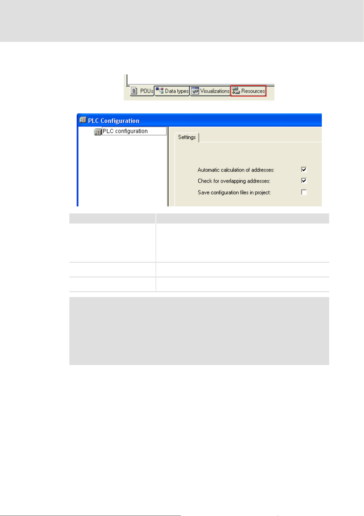
Control technology | EtherCAT communication manual
Commissioning of the system
Detailed commissioning steps
5. Create the control configuration:
•Open the Resources dialog box:
•Open the PLC Configuration dialog box:
Setting Description
Automatic calculation of addresses Every newly added module automatically gets an address which results from
Check for overlapping addresses During the compilation of the project, a check for address overlapping is
Save configuration files in project The data of the configuration file(s) *.cfg and device files on which the
the address of the module integrated before and the size of this module. If a
module is removed from the configuration, the addresses of the subsequent
modules are adapted automatically.
The ExtrasCalculate addresses menu command serves to recalculate the
addresses starting with the currently selected node (module).
carried out and overlapping addresses are indicated.
current control configuration is based are stored in the project.
Note!
We recommend to keep the standard setting. In case of a manual address
allocation, you must ensure that each object address is non-ambiguous in the
entire control configuration.
Detailed information on this can be found in the documentation for the »PLC
Designer«.
6. Add the bus interface to the PLC configuration:
Select the Append subelement BusInterface_EtherCAT command from the
PLC_configuration context menu.
70 L DMS 3.1 EN 01/2011 TD17
Page 71

Control technology | EtherCAT communication manual
Commissioning of the system
Detailed commissioning steps
7. Import the EtherCAT components (file ECAT_PLC_CFG_1.XML) for the control
configuration:
• Select the Import module command in the context menu of
BusInterface_EtherCAT:
• Select the file ECAT_PLC_CFG_1.XML from the project folder and Open:
DMS 3.1 EN 01/2011 TD17 L 71
Page 72

Control technology | EtherCAT communication manual
Commissioning of the system
Detailed commissioning steps
• When the file has been imported successfully, the Axis_IO_Group/IO_Group is
added to the configuration:
• The configuration created in the »EtherCAT Configurator« is attached below the
Axis_IO_Group/IO_Group.
Note!
• The EtherCAT components of the control configuration (device and variable
names) may only be changed in the »EtherCAT Configurator«!
Changes made in the »PLC Designer« will get overwritten at the import of the
ECAT_PLC_CFG_1.XML file.
•The Axis_IO_Group/IO_Group must not be renamed!
•The Axis_IO_Group/IO_Group is overwritten at every import of the
ECAT_PLC_CFG_1.XML file.
•The Axis_IO_Group/IO_Group is created automatically at every import of the
ECAT_PLC_CFG_1.XML file and assigned a default name.
72 L DMS 3.1 EN 01/2011 TD17
Page 73

7.2.8.2 Creating a task
How to create a task in the »PLC Designer«:
1. Select the Resources tab:
2. Select Task Configuration:
Control technology | EtherCAT communication manual
Commissioning of the system
Detailed commissioning steps
3. Select the Append Task command from the Task Configuration context menu.
4. Create a new task and make the settings relevant for the respective configuration:
Define the task cycle time. (Example in the screenshot: 1 ms)
Note!
The task cycle time must be identical with the DC cycle time set in the »EtherCAT
Configurator«.
DMS 3.1 EN 01/2011 TD17 L 73
Page 74

Control technology | EtherCAT communication manual
Commissioning of the system
Detailed commissioning steps
5. Assign a program call to the task:
• Select Attach program call in the context menu of the task.
•Open the input assistance via the button:
ü
• Select the required program from the list of user-defined programs.
6. Compile the project with <F11> or save the project.
Compiling project data
7. Assign a task to the Axis_IO_Group/IO_Group:
( 77)
74 L DMS 3.1 EN 01/2011 TD17
Page 75

Use of breakpoints
Note!
The setting of breakpoints in the PLC task assigned to the EtherCAT bus is
permissible.
Please observe:
• When reaching a breakpoint this task will be stopped.
• No new setpoints are calculated (Motion drives come to a standstill), no
deceleration ramp is generated.
• The control still sends EtherCAT frames. After restarting the PLC task, the
interrupted processing is resumed.
• Motion drives continue the interrupted motion, no acceleration ramp is
generated.
Control technology | EtherCAT communication manual
Commissioning of the system
Detailed commissioning steps
Detailed information on breakpoints can be found in the documentation/online
help for the »PLC Designer«.
DMS 3.1 EN 01/2011 TD17 L 75
Page 76
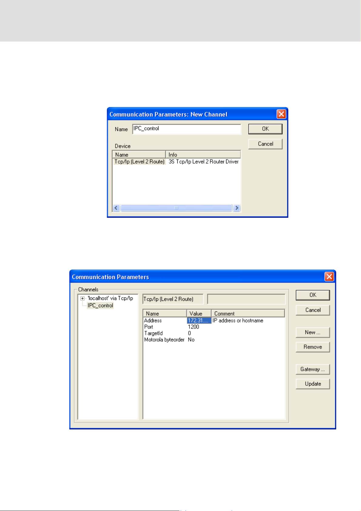
Control technology | EtherCAT communication manual
Commissioning of the system
Detailed commissioning steps
7.2.8.3 Configuring the communication parameters
Set the communication parameters to establish a connection to the respective IPC.
How to configure the communication parameters
1. Select the OnlineCommunication Parameters command:
• Enter the designation of the new channel in the Name input field.
• Confirm the entry by clicking the OK button.
2. Enter the parameters in the Values column in the Communication parameters
dialog box.
• Double-click the respective value to edit the default values:
76 L DMS 3.1 EN 01/2011 TD17
Page 77

Control technology | EtherCAT communication manual
Commissioning of the system
Detailed commissioning steps
3. Click the Gateway button to configure a gateway connection:
• Select the TCP/IP connection type from the Connection selection field.
• Confirm the selection by clicking the OK button.
7.2.8.4 Compiling project data
To compile the project data, select the ProjectBuild menu command or press the <F11>
function key.
If errors occurred during the compilation process, you can locate and eliminate them by
means of the »PLC Designer« error messages. Then compile the project data again.
If no errors occurred during the compilation process, save the »PLC Designer« project to
the project folder.
7.2.8.5 Logging on to the control system with the »PLC Designer«
To log the »PLC Designer« on to the control system, select the OnlineLogin menu
command.
For this, the PLC program must be error-free.
Confirm the appearing query dialog whether the new program is to be loaded with Yes.
DMS 3.1 EN 01/2011 TD17 L 77
Page 78

Control technology | EtherCAT communication manual
Commissioning of the system
Detailed commissioning steps
7.2.8.6 Loading the control configuration onto the IPC
How to load the control configuration onto the IPC:
1. Select the OnlineWrite file to PLC menu command.
2. Select the required file from the Write file to PLC dialog box.
3. Confirm the selection by clicking the Open button.
The file is loaded onto the IPC and saved there under the same name.
Tip!
The OnlineRead file from PLC menu command can be used to reload a file from
the IPC onto the »PLC Designer« project.
78 L DMS 3.1 EN 01/2011 TD17
Page 79

Control technology | EtherCAT communication manual
7.2.8.7 Loading the master configuration onto the EtherCAT master
The Reset (original) command serves to load the master configuration
(ECAT_MASTER_1.XML) onto the EtherCAT master:
1. Reset (original) re-initialises the EtherCAT master stack.
2. The master compares the EtherCAT configuration with the physical bus topology. If the
EtherCAT configuration is identical with the bus topology, the bus enters the Pre-
Operational state.
3. Now it is possible communicate with the slaves via the EtherCAT fieldbus.
Checking with »WebConfig« or »Engineer«
Under Master Configuration, you can check whether the configuration file
ECAT_MASTER_1.XML matches the physical bus structure.
Depending on the slot used for the EtherCAT (MC-ETC) communication card, the
parameters of the following codes should be checked:
– MC-ETC in slot 1: codes 1080.2 / 1080.3 / 1080.4
– MC-ETC in slot 2: codes 1580.2 / 1580.3 / 1580.4
Commissioning of the system
Detailed commissioning steps
If the ECAT_MASTER_1.XML configuration file corresponds to the physical bus
structure, the checksums of "ECAT Master Config" and "ECAT Stack Master" are identical
and the "ECAT Bus Scan Match" parameter has the value 1.
7.2.8.8 Loading and starting the PLC program
Select the OnlineDownload menu command to load the PLC program included in the
configuration onto the control system.
Select the OnlineRun menu command to start the PLC program.
DMS 3.1 EN 01/2011 TD17 L 79
Page 80

Control technology | EtherCAT communication manual
Commissioning of the system
Checking the system startup
7.3 Checking the system startup
Note!
Checking of the system startup is only possible for SoftMotion target systems.
To check whether the system has started up correctly, you can do the following
Evaluation of the boot-up error message of the SM_DriveBasic.lib library
Evaluation of the Axis_IO_Group state
Evaluation of the axis state
7.3.1 Evaluation of the boot-up error message of the SM_DriveBasic.lib library
To check that the system has started up correctly, you can evaluate the boot-up error. For
this purpose, the scope of the global variables contained in the SM_DriveBasic.lib library
includes the element g_strBootupError. This element displays error messages in text
form:
g_strBootupError = no error
no error indicates that the system has started up correctly:
( 82).
( 81);
( 80);
80 L DMS 3.1 EN 01/2011 TD17
Page 81
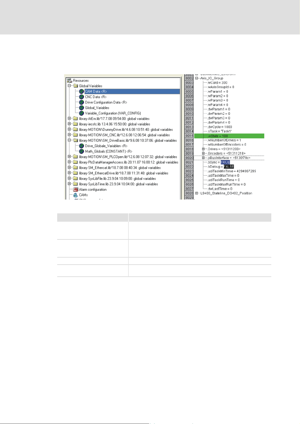
Control technology | EtherCAT communication manual
7.3.2 Evaluation of the Axis_IO_Group state
The Axis_IO_Group structure contains the global variable wState.
The following value ranges have to be evaluated for the system startup check:
Commissioning of the system
Checking the system startup
The value of the wState variable has the following meaning:
State of the Axis_IO_Group State of the system
wState = 0 •Initial state
•Project loaded
• PLC in stop
wState = 1...99 • System is starting up
•Project loaded
•PLC started
wState = 100 • System has started up successfully
wState > 1000 • Error occurred during startup, compare error message in
g_strBootupError
DMS 3.1 EN 01/2011 TD17 L 81
Page 82

Control technology | EtherCAT communication manual
Commissioning of the system
Checking the system startup
7.3.3 Evaluation of the axis state
The global Ax_Ref structure of the Motion axes contains the element bCommunication:
The following axis states have to be evaluated:
State of the axis State of the system
bCommunication = true Cyclic communication is functioning properly.
bCommunication = false Cyclic communication is not functioning properly.
82 L DMS 3.1 EN 01/2011 TD17
Page 83

Control technology | EtherCAT communication manual
7.4 Typical commissioning scenarios
In this chapter you will find typical commissioning scenarios and the corresponding state
diagrams, which will help you to carry out simple analyses of the system behaviour.
7.4.1 Switching on a completely configured system
Initial situation:
The PLC application has been loaded on the IPC.
The ECAT_Master_1.XML file matching the bus topology is available on the IPC.
System behaviour:
The system starts up automatically.
Commissioning of the system
Typical commissioning scenarios
DMS 3.1 EN 01/2011 TD17 L 83
Page 84

Control technology | EtherCAT communication manual
Commissioning of the system
Typical commissioning scenarios
Switch on industrial PC and field devices
PLC: Original
EtherCAT: Unknown
Read ECAT_MASTER_1.XML
PLC: Original
EtherCAT: Init
PLC: Original
EtherCAT: Pre-Operational
PLC: Running
EtherCAT: Safe-Operational
PLC: Running
EtherCAT: Operational
System is running
Legend
PLC:
EtherCAT:
PLC:
EtherCAT:
Reset
(origin)
Transient state of PLC and EtherCAT
Automatic change to next state
Steady state of PLC and EtherCAT
Change to next by means of an external
action
Reset the PLC.
The PLC application is deleted.
Load PLC Load PLC application
Start PLC Start PLC application
84 L DMS 3.1 EN 01/2011 TD17
Page 85

Control technology | EtherCAT communication manual
7.4.2 Switching on a system with an incomplete configuration
Initial situation:
The PLC application has been loaded on the IPC.
The ECAT_Master_1.XML file is not available on the IPC or does not match the physical
bus topology.
System behaviour:
EtherCAT remains in "Unknown" state.
The PLC does not start up.
How to complete the configuration:
1. Load the correct "ECAT_Master_1.xml" file onto the IPC.
2. Execute "Reset (Original)".
– The PLC is reset, the PLC application is deleted.
Commissioning of the system
Typical commissioning scenarios
3. The system starts up.
– You have to manually load and start the PLC application.
DMS 3.1 EN 01/2011 TD17 L 85
Page 86

Control technology | EtherCAT communication manual
Commissioning of the system
Typical commissioning scenarios
Switch on industrial PC and field devices
PLC: Original
EtherCAT: Unknown
ECAT_MASTER_1.XML
available?
YES
Read ECAT_MASTER_1.XML
PLC: Original
EtherCAT: Init
ECAT_MASTER_1.XML
OK?
YES
NO
NO
PLC: Original
EtherCAT: Unknown
Load PLC
PLC: Stop
EtherCAT: Unknown
Load correct
ECAT_MASTER_1.XML
onto IPC
Reset
(Original)
Reset
(Original)
PLC: Original
EtherCAT: Pre-Operational
Load PLC
PLC: Stop
EtherCAT: Pre-Operational
Start PLC
Legend
PLC:
EtherCAT:
PLC:
EtherCAT:
Reset
(origin)
PLC: Running
EtherCAT: Safe-Operational
PLC: Running
EtherCAT: Operational
System is running
Transient state of PLC and EtherCAT
Automatic change to next state
Steady state of PLC and EtherCAT
Change to next by means of an external
action
Reset the PLC.
The PLC application is deleted.
Load PLC Load PLC application
Start PLC Start PLC application
86 L DMS 3.1 EN 01/2011 TD17
Page 87

Control technology | EtherCAT communication manual
Commissioning of the system
Typical commissioning scenarios
7.4.3 Updating the PLC application while the EtherCAT configuration remains unchanged
Initial situation:
PLC and EtherCAT are running.
– PLC state: Running
– EtherCAT state: Operational
How to update the PLC application:
1. Stop the PLC.
2. Execute "Reset (Original)".
• The PLC is reset, the PLC application is deleted.
3. The system starts up.
• You have to manually load and start the PLC application.
DMS 3.1 EN 01/2011 TD17 L 87
Page 88

Control technology | EtherCAT communication manual
Commissioning of the system
Typical commissioning scenarios
PLC: Original
EtherCAT: Unknown
Read ECAT_MASTER_1.XML
PLC: Original
EtherCAT: Init
PLC: Original
Start
EtherCAT: Pre-Operational
Load PLC
PLC: Stop
EtherCAT: Pre-Operational
Start PLC
PLC: Running
EtherCAT: Safe-Operational
PLC: Running
EtherCAT: Operational
System is running
Stop PLC
PLC: Stop
EtherCAT: Pre-Operational
Reset
(Original)
Legend
PLC:
EtherCAT:
PLC:
EtherCAT:
Transient state of PLC and EtherCAT
Automatic change to next state
Steady state of PLC and EtherCAT
Change to next by means of an external
Load PLC Load PLC application
Start PLC Start PLC application
action
Reset
(origin)
Reset the PLC.
The PLC application is deleted.
Start Beginning of the scenario
88 L DMS 3.1 EN 01/2011 TD17
Page 89
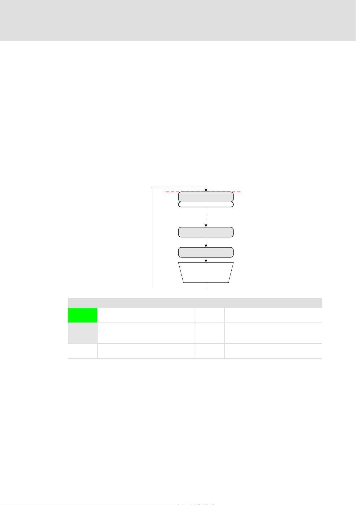
Control technology | EtherCAT communication manual
Commissioning of the system
Typical commissioning scenarios
7.4.4 Stopping and starting the PLC while the configuration remains unchanged
Initial situation:
PLC and EtherCAT are running.
– PLC state: Running
– EtherCAT state: Operational
How to stop and start the PLC:
1. Stop the PLC.
2. Start the PLC.
3. The PLC application must call the "SMC_ResetAxisGroup" program organisation
unit.
4. The system is running again.
Legend
PLC:
EtherCAT:
PLC:
EtherCAT:
Reset
(origin)
Start
Transient state of PLC and EtherCAT
Automatic change to next state
Steady state of PLC and EtherCAT
Change to next by means of an external
action
Reset the PLC.
The PLC application is deleted.
PLC: Running
EtherCAT: Operational
PLC: Stop
EtherCAT: Pre-Operational
PLC: Running
EtherCAT: Safe-Operational
System is running
Stop PLC
Start PLC
Call
<SMC_ResetAxisGroup>
POU
from PLC application
Load PLC Load PLC application
Start PLC Start PLC application
Start Beginning of the scenario
DMS 3.1 EN 01/2011 TD17 L 89
Page 90

Control technology | EtherCAT communication manual
Commissioning of the system
Detailed overview of the commissioning steps
7.5 Detailed overview of the commissioning steps
In the following diagram the individual commissioning steps and their processing order
are summarised once again. Detailed information on the individual processing steps can
be found in the chapter Detailed commissioning steps
( 45).
90 L DMS 3.1 EN 01/2011 TD17
Page 91

Control technology | EtherCAT communication manual
8 EtherCAT with CANopen or PROFIBUS
Note!
A mixed operation is only possible with industrial PCs which have two additional
slots for communcation cards. A mixed operation is not possible with the
"Command Station".
The EtherCAT bus system can be combined with CANopen or PROFIBUS. This makes sense
if not all field devices are available for the same bus system or a motion bus is required
parallelly to the PROFIBUS. The bus systems are sychronised in the control.
The following combinations are allowed:
CANopen and EtherCAT
– CANopen configuration in the »PLC Designer«
– EtherCAT configuration in the »EtherCAT Configurator«
EtherCAT with CANopen or PROFIBUS
PROFIBUS (as logic bus) and EtherCAT (as motion bus)
– PROFIBUS configuration in the »PLC Designer«
– EtherCAT configuration in the »EtherCAT Configurator«
Communication manual "CANopen control technology"
Here you can find detailed information on how to commission CANopen
components.
Communication manual "PROFIBUS control technology"
Here you can find detailed information on how to commission PROFIBUS
components.
DMS 3.1 EN 01/2011 TD17 L 91
Page 92

Control technology | EtherCAT communication manual
EtherCAT with CANopen or PROFIBUS
Addressing the PROFIBUS and CANopen stations
8.1 Addressing the PROFIBUS and CANopen stations
The addresses for input and output objects of the PROFIBUS and CANopen stations are
automatically allocated in the »PLC Designer« (standard setting):
Note!
We recommend to keep the standard setting. In case of a manual address
allocation, you must ensure that each object address is non-ambiguous in the
entire control configuration.
Detailed information on this can be found in the documentation/online help of
the »PLC Designer«.
92 L DMS 3.1 EN 01/2011 TD17
Page 93

Control technology | EtherCAT communication manual
EtherCAT with CANopen or PROFIBUS
Addressing EtherCAT nodes using CANopen/PROFIBUS nodes
8.2 Addressing EtherCAT nodes using CANopen/PROFIBUS nodes
The addresses for input and output objects of the EtherCAT stations are allocated in the
»EtherCAT Configurator«. Afterwards, the EtherCAT configuration is imported into the
»PLC Designer« control configuration.
There are two cases for the control configuration in the »PLC Designer«:
1. PROFIBUS/CANopen before EtherCAT:
– Keep the standard settings for address allocation for the PROFIBUS/CANopen
stations in the »PLC Designer« control configuration. (The addressing of the
PROFIBUS/CAN stations starts with ’0’.)
– Define a sufficient address offset for the first input and output object in the
»EtherCAT Configurator« at the first EtherCAT slave (> PROFIBUS/CAN addresses).
The addresses of the other input and output objects are updated automatically after
the entry.
Thus, address conflicts can be prevented after the import of the EtherCAT
configuration into the »PLC Designer« control configuration.
2. EtherCAT before PROFIBUS/CANopen:
– Do not define any address offsets in the »EtherCAT Configurator«. (The addressing of
the EtherCAT stations starts with ’0’.)
– For PROFIBUS/CANopen stations, no address offsets must be defined in the »PLC
Designer« control configuration. If address offsets are defined, the offsets must be
greater than the EtherCAT addresses.
Settings in the »EtherCAT Configurator«
( 94)
DMS 3.1 EN 01/2011 TD17 L 93
Page 94

Control technology | EtherCAT communication manual
EtherCAT with CANopen or PROFIBUS
Addressing EtherCAT nodes using CANopen/PROFIBUS nodes
Settings in the »EtherCAT Configurator«
Assign non-ambiguous variable names to the input and output objects according to
IEC 61131 syntax (no blanks and leading digits in the variable name). After the import
of the EtherCAT configuration into the »PLC Designer« control configuration,
corresponding system variables are available for the PLC program.
Note!
Always use the system variables within the PLC program in order to access the
input and output objects or assign values to them.
By double-clicking the corresponding fields, you can make the adjustments:
In the example, variable names have been assigned to the first three output objects.
Moreover, an offset of ’1000’ has been entered for the first output object (%QW...) and the
first input object (%IW...).
The »EtherCAT Configurator« does not work with byte addresses. The objects are
addressed with the byte address in the control configuration:
Objects Addresses in the
»EtherCAT Configurator«
Output objects %QX1000.0 %QB1000
%QB1000 %QB1000
%QW1000 %QB500
%QD1000 %QB250
Input objects %IX1000.0 %IB1000
%IB1000 %IB1000
%IW1000 %IB500
%ID1000 %IB250
Byte addresses
94 L DMS 3.1 EN 01/2011 TD17
Page 95

Control technology | EtherCAT communication manual
EtherCAT with CANopen or PROFIBUS
Addressing EtherCAT nodes using CANopen/PROFIBUS nodes
In the »PLC Designer«, the output and input objects are "byte-addressed". The original
address offset of ’1000’ (word level) for the first output and input objects is set accordingly
to '2000" after the import of the EtherCAT configuration. The addresses of the other input
and output objects are also updated.
Note!
• Changes of the EtherCAT configuration in the »PLC Designer« are overwritten
when the EtherCAT configuration is re-imported.
Always adapt the EtherCAT configuration to the »EtherCAT Configurator«.
• In a mixed operation, it must always be ensured that the CAN-Motion task
has the highest priority. The task assigned to the EtherCAT bus should have
the second-highest priority. The tasks assigned to the Logic bus systems
should be configured with a lower priority.
DMS 3.1 EN 01/2011 TD17 L 95
Page 96

Control technology | EtherCAT communication manual
EtherCAT function libraries
Usability
9 EtherCAT function libraries
The SM_Ethercat.lib and AtEm.LIB function libraries contain function blocks and functions
that are required for the creation of your »PLC Designer« project.
These function blocks and functions support:
The setting and reading of the master/slave states;
The network management;
The network diagnostics;
The upload and download of CoE parameters.
9.1 Usability
The SM_Ethercat.lib and AtEm.LIB function libraries are integrated in the following target
systems:
L-force Logic x700 from version 6.x
L-force Motion x700 from version 6.x
Via the Library manager of the »PLC Designer« you can integrate the function libraries into
the »PLC Designer« project. They can be found in the library directory of the corresponding
target system in the subdirectory "EtherCAT".
Note!
The integration of the SM_EthercatDrive.lib function library into a »PLC
Designer« project is not required, as the function blocks and the functions of this
library are not relevant.
In the course of this chapter only the function blocks and functions required for
the creation of a »PLC Designer« project are described.
96 L DMS 3.1 EN 01/2011 TD17
Page 97

Control technology | EtherCAT communication manual
EtherCAT function libraries
Function blocks/functions required for a »PLC Designer« project (overview)
9.2 Function blocks/functions required for a »PLC Designer« project (overview)
Note!
Use the function blocks and functions of the function library AtEm.lib only if the
master is configured completely. Otherwise it can lead to instabilities of the
control system. A check of the master configuration can be executed with the
ecatMasterIsConfigured (FUN)
Function library Function block (FB) / function (FUN)
SM_Ethercat.lib ECATDiagnostic (FB)
ResetMasterStatus (FB)
SMC_ETCErrorString (FUN)
L_ECAT_ReadErrCnt (FB)
L_ECAT_ResetErrCnt (FB)
AtEm.lib ecatCoeSdoDownloadReq (FB)
ecatCoeSdoUploadReq (FB)
ecatGetMasterState (FUN)
ecatGetNumConfiguredSlaves (FUN)
ecatGetNumConnectedSlaves (FUN)
ecatGetSlaveId (FUN)
ecatGetSlaveIdAtPosition (FUN)
ecatGetSlaveProp (FUN)
ecatGetSlaveState (FUN)
ecatGetSlaveStateAsync (FB)
ecatMasterIsConfigured (FUN)
ecatSetMasterStateAsync (FB)
ecatSetSlaveStateAsync (FB) ( 103)
ecatStartAsync (FB)
ecatStopAsync (FB) ( 101)
The global EtherCAT master structure ECAT_MASTER
( 108) function.
( 113)
( 114)
( 115)
( 116)
( 117)
( 122)
( 123)
( 105)
( 112)
( 113)
( 109)
( 110)
( 111)
( 106)
( 107)
( 108)
( 102)
( 100)
( 118)
DMS 3.1 EN 01/2011 TD17 L 97
Page 98

Control technology | EtherCAT communication manual
EtherCAT function libraries
Properties of function blocks
9.3 Properties of function blocks
The function blocks are equipped with inputs and outputs for the activation of the POU,
the display of the current POU status, and for the output of error messages:
Input/output Data type Action
bExecute / bEnable BOOL bExecute and bEnable are edge-controlled:
In the case of a positive edge, the function block is executed.
bBusy BOOL As long as a function block is executed, bBusy is TRUE and bDone is FALSE.
bDone BOOL If a function block has been executed, bDone is set to TRUE and bBusy is set
bError BOOL If an error has occurred, bError is set to TRUE.
dwErrorCode DWORD If an error has occurred (output bError = TRUE), a hexadecimal error code (see
to FALSE.
If bExecute/bEnable has been reset, bDone is only active during the function
block call. If bExecute/bEnable is TRUE, then bDone remains TRUE as long as
bExecute/bEnable is reset.
also System error messages ( 157)) is displayed at the output dwErrorCode.
The error code is only available during the function block call (if
bDone =TRUE).
9.4 The EC_T_STATE structure
Note!
The ECAT_STATE structure describes all possible states of the EtherCAT bus system:
Status Identifier Value (DINT)
Unknown eEcatState_UNKNOWN 0
Initialization eEcatState_INIT 1
Pre-Operational eEcatState_PREOP 2
Bootstrap Mode
(Is currently not supported.)
Safe-Operational eEcatState_SAFEOP 4
Operational eEcatState_OP 8
The identifiers itemised here cannot be found in IEC 61131. For all state inputs
and outputs, always the numerical values are indicated.
eEcatState_BOOT 3
98 L DMS 3.1 EN 01/2011 TD17
Page 99

Control technology | EtherCAT communication manual
Function blocks and functions for master/slave states
9.5 Function blocks and functions for master/slave states
The function blocks and functions described in the following support the setting and
reading of the master/slave states.
EtherCAT function libraries
ecatStartAsync (FB)
ecatStopAsync (FB) ( 101)
ecatSetMasterStateAsync (FB) ( 102)
ecatSetSlaveStateAsync (FB) ( 103)
ecatGetMasterState (FUN) ( 105)
ecatGetSlaveState (FUN) ( 106)
ecatGetSlaveStateAsync (FB) ( 107)
( 100)
DMS 3.1 EN 01/2011 TD17 L 99
Page 100
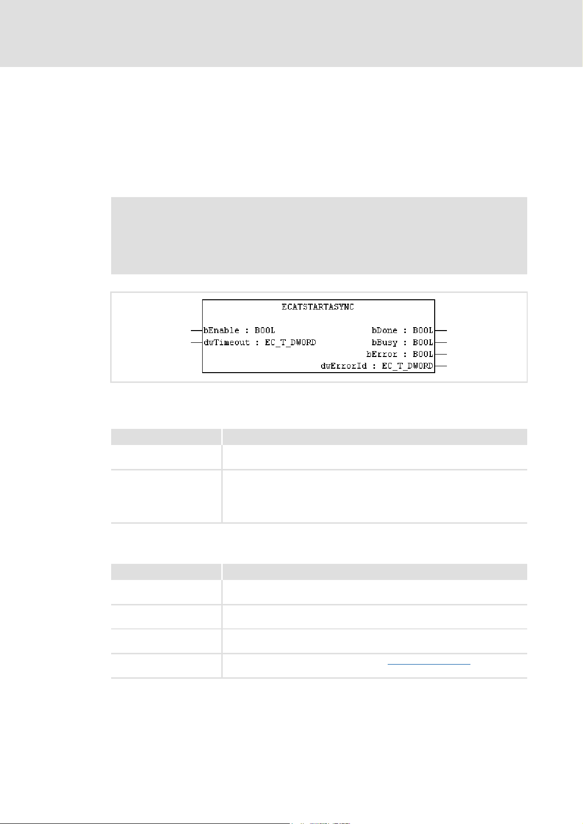
Control technology | EtherCAT communication manual
EtherCAT function libraries
Function blocks and functions for master/slave states
9.5.1 ecatStartAsync (FB)
Function: This function block sets the master and all slaves connected to the
Operational status.
Library: AtEm.lib
Visualisation: VISU_ecatStartAsync
Note!
State changes are usually carried out automatically by the control system. By
means of this function block you can change the state manually. Please note
that the bus system may become unstable if the state is changed manually.
Inputs (VAR_INPUT)
Identifier/data type Meaning/possible settings
bEnable
dwTimeout
DWORD
Outputs (VAR_OUTPUT)
Identifier/data type Meaning/possible settings
bDone
bBusy
bError
dwErrorCode
DWORD
The function block is activated in an edge-controlled manner:
BOOL
• Positive edge (TRUE) = function block is executed.
Time-out in milliseconds
• If the action could not be carried out successfully after time-out, bError is set
to TRUE.
• The time required for the action depends on the structure of the EtherCAT
network.
FALSE: Function block is active or has not been called
BOOL
TRUE: Function block has been executed.
FALSE: Function block is not active.
BOOL
TRUE: Function block is active.
FALSE: No error
BOOL
TRUE: An error has occurred.
Display of a hexadecimal error code (see also System error messages
error has occurred (bError =TRUE).
( 157)) if an
100 L DMS 3.1 EN 01/2011 TD17
 Loading...