

Page 1
Automation Systems
Controller-based
Automation
EtherCAT®
_ _ _ _ _ _ _ _ _ _ _ _ _ _ _ _ _ _ _ _ _ _ _ _ _ _ _ _ _ _ _ _ _
Communication Manual EN
Ä.O5ôä
13462095
L
Page 2

Contents
_ _ _ _ _ _ _ _ _ _ _ _ _ _ _ _ _ _ _ _ _ _ _ _ _ _ _ _ _ _ _ _ _ _ _ _ _ _ _ _ _ _ _ _ _ _ _ _ _ _ _ _ _ _ _ _ _ _ _ _ _ _ _ _
1 About this documentation _ _ _ _ _ _ _ _ _ _ _ _ _ _ _ _ _ _ _ _ _ _ _ _ _ _ _ _ _ _ _ _ _ _ _ _ _ _ _ 6
1.1 Document history _ _ _ _ _ _ _ _ _ _ _ _ _ _ _ _ _ _ _ _ _ _ _ _ _ _ _ _ _ _ _ _ _ _ _ _ _ _ _ _ _ _ _ _ 8
1.2 Conventions used _ _ _ _ _ _ _ _ _ _ _ _ _ _ _ _ _ _ _ _ _ _ _ _ _ _ _ _ _ _ _ _ _ _ _ _ _ _ _ _ _ _ _ _ 9
1.3 Terminology used _ _ _ _ _ _ _ _ _ _ _ _ _ _ _ _ _ _ _ _ _ _ _ _ _ _ _ _ _ _ _ _ _ _ _ _ _ _ _ _ _ _ _ _ 10
1.4 Definition of the notes used _ _ _ _ _ _ _ _ _ _ _ _ _ _ _ _ _ _ _ _ _ _ _ _ _ _ _ _ _ _ _ _ _ _ _ _ _ _ 12
2Safety instructions _ _ _ _ _ _ _ _ _ _ _ _ _ _ _ _ _ _ _ _ _ _ _ _ _ _ _ _ _ _ _ _ _ _ _ _ _ _ _ _ _ _ _ _ 13
3 Controller-based Automation: Central motion control _ _ _ _ _ _ _ _ _ _ _ _ _ _ _ _ _ _ _ _ _ _ _ _ 14
4 The Lenze automation system with EtherCAT _ _ _ _ _ _ _ _ _ _ _ _ _ _ _ _ _ _ _ _ _ _ _ _ _ _ _ _ _ 17
4.1 Brief description of EtherCAT _ _ _ _ _ _ _ _ _ _ _ _ _ _ _ _ _ _ _ _ _ _ _ _ _ _ _ _ _ _ _ _ _ _ _ _ _ _ 17
4.1.1 Structure of the EtherCAT bus system _ _ _ _ _ _ _ _ _ _ _ _ _ _ _ _ _ _ _ _ _ _ _ _ _ _ _ _ 18
4.1.2 Communication _ _ _ _ _ _ _ _ _ _ _ _ _ _ _ _ _ _ _ _ _ _ _ _ _ _ _ _ _ _ _ _ _ _ _ _ _ _ _ _ 19
4.1.2.1 The EtherCAT state machine _ _ _ _ _ _ _ _ _ _ _ _ _ _ _ _ _ _ _ _ _ _ _ _ _ _ _ 20
4.1.2.2 Addressing of the slaves _ _ _ _ _ _ _ _ _ _ _ _ _ _ _ _ _ _ _ _ _ _ _ _ _ _ _ _ _ 22
4.1.2.3 Working counter _ _ _ _ _ _ _ _ _ _ _ _ _ _ _ _ _ _ _ _ _ _ _ _ _ _ _ _ _ _ _ _ _ _ 23
4.2 Required hardware components _ _ _ _ _ _ _ _ _ _ _ _ _ _ _ _ _ _ _ _ _ _ _ _ _ _ _ _ _ _ _ _ _ _ _ _ 24
4.2.1 Field devices _ _ _ _ _ _ _ _ _ _ _ _ _ _ _ _ _ _ _ _ _ _ _ _ _ _ _ _ _ _ _ _ _ _ _ _ _ _ _ _ _ _ 24
4.2.2 The Lenze Controller - the central component _ _ _ _ _ _ _ _ _ _ _ _ _ _ _ _ _ _ _ _ _ _ _ _ 25
4.2.3 EtherCAT product codes _ _ _ _ _ _ _ _ _ _ _ _ _ _ _ _ _ _ _ _ _ _ _ _ _ _ _ _ _ _ _ _ _ _ _ _ 26
4.2.4 The EtherCAT interface of the Lenze Controller _ _ _ _ _ _ _ _ _ _ _ _ _ _ _ _ _ _ _ _ _ _ _ 28
4.3 Lenze Engineering tools _ _ _ _ _ _ _ _ _ _ _ _ _ _ _ _ _ _ _ _ _ _ _ _ _ _ _ _ _ _ _ _ _ _ _ _ _ _ _ _ _ 29
4.4 Interaction of the components _ _ _ _ _ _ _ _ _ _ _ _ _ _ _ _ _ _ _ _ _ _ _ _ _ _ _ _ _ _ _ _ _ _ _ _ _ 30
4.4.1 The state machine of the Lenze control technology _ _ _ _ _ _ _ _ _ _ _ _ _ _ _ _ _ _ _ _ _ 30
4.4.2 Communication between the Engineering PC and the field devices _ _ _ _ _ _ _ _ _ _ _ _ 32
4.4.2.1 EtherCAT bus not in operation _ _ _ _ _ _ _ _ _ _ _ _ _ _ _ _ _ _ _ _ _ _ _ _ _ _ 32
4.4.2.2 EtherCAT bus in operation (gateway function) _ _ _ _ _ _ _ _ _ _ _ _ _ _ _ _ _ 33
5 Technical data _ _ _ _ _ _ _ _ _ _ _ _ _ _ _ _ _ _ _ _ _ _ _ _ _ _ _ _ _ _ _ _ _ _ _ _ _ _ _ _ _ _ _ _ _ _ 34
5.1 General data _ _ _ _ _ _ _ _ _ _ _ _ _ _ _ _ _ _ _ _ _ _ _ _ _ _ _ _ _ _ _ _ _ _ _ _ _ _ _ _ _ _ _ _ _ _ _ 34
5.2 EtherCAT interface of the Lenze Controller _ _ _ _ _ _ _ _ _ _ _ _ _ _ _ _ _ _ _ _ _ _ _ _ _ _ _ _ _ _ 34
5.3 Communication times and drive-specific data _ _ _ _ _ _ _ _ _ _ _ _ _ _ _ _ _ _ _ _ _ _ _ _ _ _ _ _ _ 35
6 Synchronisation with "Distributed clocks" (DC) _ _ _ _ _ _ _ _ _ _ _ _ _ _ _ _ _ _ _ _ _ _ _ _ _ _ _ _ 36
6.1 Synchronous communication _ _ _ _ _ _ _ _ _ _ _ _ _ _ _ _ _ _ _ _ _ _ _ _ _ _ _ _ _ _ _ _ _ _ _ _ _ _ 37
6.2 Test of DC synchronicity _ _ _ _ _ _ _ _ _ _ _ _ _ _ _ _ _ _ _ _ _ _ _ _ _ _ _ _ _ _ _ _ _ _ _ _ _ _ _ _ _ 38
2 Lenze · Controller-based Automation · EtherCAT® Communication Manual · DMS 6.4 EN · 04/2014 · TD17
Page 3

Contents
_ _ _ _ _ _ _ _ _ _ _ _ _ _ _ _ _ _ _ _ _ _ _ _ _ _ _ _ _ _ _ _ _ _ _ _ _ _ _ _ _ _ _ _ _ _ _ _ _ _ _ _ _ _ _ _ _ _ _ _ _ _ _ _
7 Commissioning of the system _ _ _ _ _ _ _ _ _ _ _ _ _ _ _ _ _ _ _ _ _ _ _ _ _ _ _ _ _ _ _ _ _ _ _ _ _ 39
7.1 Sample projects (Application Samples) _ _ _ _ _ _ _ _ _ _ _ _ _ _ _ _ _ _ _ _ _ _ _ _ _ _ _ _ _ _ _ _ _ 39
7.2 Overview of the commissioning steps _ _ _ _ _ _ _ _ _ _ _ _ _ _ _ _ _ _ _ _ _ _ _ _ _ _ _ _ _ _ _ _ _ 40
7.3 Detailed description of the commissioning steps _ _ _ _ _ _ _ _ _ _ _ _ _ _ _ _ _ _ _ _ _ _ _ _ _ _ _ 42
7.3.1 Planning the bus topology _ _ _ _ _ _ _ _ _ _ _ _ _ _ _ _ _ _ _ _ _ _ _ _ _ _ _ _ _ _ _ _ _ _ _ 42
7.3.2 Installing field devices _ _ _ _ _ _ _ _ _ _ _ _ _ _ _ _ _ _ _ _ _ _ _ _ _ _ _ _ _ _ _ _ _ _ _ _ _ 43
7.3.3 Create a project folder _ _ _ _ _ _ _ _ _ _ _ _ _ _ _ _ _ _ _ _ _ _ _ _ _ _ _ _ _ _ _ _ _ _ _ _ _ 43
7.3.4 Commissioning the i700 servo inverter _ _ _ _ _ _ _ _ _ _ _ _ _ _ _ _ _ _ _ _ _ _ _ _ _ _ _ _ 44
7.3.4.1 i700 parameter management in the Controller-based Automation
system _ _ _ _ _ _ _ _ _ _ _ _ _ _ _ _ _ _ _ _ _ _ _ _ _ _ _ _ _ _ _ _ _ _ _ _ _ _ _ 45
7.3.4.2 i700 parameter management in »EASY Starter« _ _ _ _ _ _ _ _ _ _ _ _ _ _ _ _ 49
7.3.4.3 Exchanging i700 parameter sets between »PLC Designer« and
»EASY Starter« _ _ _ _ _ _ _ _ _ _ _ _ _ _ _ _ _ _ _ _ _ _ _ _ _ _ _ _ _ _ _ _ _ _ _ 51
7.3.4.4 Overview of the commissioning steps _ _ _ _ _ _ _ _ _ _ _ _ _ _ _ _ _ _ _ _ _ _ 52
7.3.4.5 Checking the wiring _ _ _ _ _ _ _ _ _ _ _ _ _ _ _ _ _ _ _ _ _ _ _ _ _ _ _ _ _ _ _ _ 53
7.3.4.6 Entering motor and controller settings _ _ _ _ _ _ _ _ _ _ _ _ _ _ _ _ _ _ _ _ _ 54
7.3.4.7 Setting the feedback system for servo control _ _ _ _ _ _ _ _ _ _ _ _ _ _ _ _ _ _ 57
7.3.4.8 Integrating the L_SMC_AxisBasicControl function block _ _ _ _ _ _ _ _ _ _ _ _ 59
7.3.4.9 Executing manual control _ _ _ _ _ _ _ _ _ _ _ _ _ _ _ _ _ _ _ _ _ _ _ _ _ _ _ _ _ 65
7.3.4.10 Optimising control _ _ _ _ _ _ _ _ _ _ _ _ _ _ _ _ _ _ _ _ _ _ _ _ _ _ _ _ _ _ _ _ 67
7.3.5 Commissioning other Lenze field devices _ _ _ _ _ _ _ _ _ _ _ _ _ _ _ _ _ _ _ _ _ _ _ _ _ _ 70
7.3.6 Creating a PLC program with a target system (Logic/Motion) _ _ _ _ _ _ _ _ _ _ _ _ _ _ _ _ 71
7.3.7 Configuring the communication parameters _ _ _ _ _ _ _ _ _ _ _ _ _ _ _ _ _ _ _ _ _ _ _ _ 73
7.3.8 Determining the physical EtherCAT configuration (fieldbus scan) _ _ _ _ _ _ _ _ _ _ _ _ _ 75
7.3.9 Importing missing devices / device description files _ _ _ _ _ _ _ _ _ _ _ _ _ _ _ _ _ _ _ _ _ 78
7.3.10 Creating a control configuration (adding field devices) _ _ _ _ _ _ _ _ _ _ _ _ _ _ _ _ _ _ _ 79
7.3.11 Creating a task _ _ _ _ _ _ _ _ _ _ _ _ _ _ _ _ _ _ _ _ _ _ _ _ _ _ _ _ _ _ _ _ _ _ _ _ _ _ _ _ _ 82
7.3.12 Setting a DC synchronisation _ _ _ _ _ _ _ _ _ _ _ _ _ _ _ _ _ _ _ _ _ _ _ _ _ _ _ _ _ _ _ _ _ 87
7.3.13 Setting SoftMotion parameters _ _ _ _ _ _ _ _ _ _ _ _ _ _ _ _ _ _ _ _ _ _ _ _ _ _ _ _ _ _ _ _ 92
7.3.14 Processing EtherCAT I/O mapping _ _ _ _ _ _ _ _ _ _ _ _ _ _ _ _ _ _ _ _ _ _ _ _ _ _ _ _ _ _ 95
7.3.14.1 Entering the settings for PDO mapping _ _ _ _ _ _ _ _ _ _ _ _ _ _ _ _ _ _ _ _ _ 96
7.3.14.2 Configuring individual PDO mapping _ _ _ _ _ _ _ _ _ _ _ _ _ _ _ _ _ _ _ _ _ _ 97
7.3.14.3 PDO mapping for logic devices _ _ _ _ _ _ _ _ _ _ _ _ _ _ _ _ _ _ _ _ _ _ _ _ _ _ 100
7.3.14.4 Using PDO mapping settings from »Engineer« _ _ _ _ _ _ _ _ _ _ _ _ _ _ _ _ _ 101
7.3.15 Compiling the PLC program code _ _ _ _ _ _ _ _ _ _ _ _ _ _ _ _ _ _ _ _ _ _ _ _ _ _ _ _ _ _ _ 103
7.3.16 Logging in on the controller with the »PLC Designer« _ _ _ _ _ _ _ _ _ _ _ _ _ _ _ _ _ _ _ _ 103
7.3.17 Starting the PLC program _ _ _ _ _ _ _ _ _ _ _ _ _ _ _ _ _ _ _ _ _ _ _ _ _ _ _ _ _ _ _ _ _ _ _ 103
7.3.18 Start parameters of the Servo Drives 9400 HighLine CiA 402 _ _ _ _ _ _ _ _ _ _ _ _ _ _ _ _ 103
7.3.19 Optimising the task utilisation _ _ _ _ _ _ _ _ _ _ _ _ _ _ _ _ _ _ _ _ _ _ _ _ _ _ _ _ _ _ _ _ 104
7.4 State diagram for commissioning _ _ _ _ _ _ _ _ _ _ _ _ _ _ _ _ _ _ _ _ _ _ _ _ _ _ _ _ _ _ _ _ _ _ _ 105
8 Mixed operation - EtherCAT with other bus systems _ _ _ _ _ _ _ _ _ _ _ _ _ _ _ _ _ _ _ _ _ _ _ _ _ 106
8.1 CANopen and EtherCAT _ _ _ _ _ _ _ _ _ _ _ _ _ _ _ _ _ _ _ _ _ _ _ _ _ _ _ _ _ _ _ _ _ _ _ _ _ _ _ _ _ 107
8.2 PROFIBUS as the logic bus and EtherCAT as a logic bus or motion bus _ _ _ _ _ _ _ _ _ _ _ _ _ _ _ _ 108
8.3 EtherCAT and PROFINET _ _ _ _ _ _ _ _ _ _ _ _ _ _ _ _ _ _ _ _ _ _ _ _ _ _ _ _ _ _ _ _ _ _ _ _ _ _ _ _ _ 109
Lenze · Controller-based Automation · EtherCAT® Communication Manual · DMS 6.4 EN · 04/2014 · TD17 3
Page 4

Contents
_ _ _ _ _ _ _ _ _ _ _ _ _ _ _ _ _ _ _ _ _ _ _ _ _ _ _ _ _ _ _ _ _ _ _ _ _ _ _ _ _ _ _ _ _ _ _ _ _ _ _ _ _ _ _ _ _ _ _ _ _ _ _ _
9 Function library L_IODrvEtherCAT.lib _ _ _ _ _ _ _ _ _ _ _ _ _ _ _ _ _ _ _ _ _ _ _ _ _ _ _ _ _ _ _ _ _ 110
9.1 Overview of functions and function blocks _ _ _ _ _ _ _ _ _ _ _ _ _ _ _ _ _ _ _ _ _ _ _ _ _ _ _ _ _ _ 114
9.2 CoE Interface _ _ _ _ _ _ _ _ _ _ _ _ _ _ _ _ _ _ _ _ _ _ _ _ _ _ _ _ _ _ _ _ _ _ _ _ _ _ _ _ _ _ _ _ _ _ _ 115
9.2.1 Reading and writing parameters _ _ _ _ _ _ _ _ _ _ _ _ _ _ _ _ _ _ _ _ _ _ _ _ _ _ _ _ _ _ _ 115
9.2.1.1 Reading parameters (SDO upload) _ _ _ _ _ _ _ _ _ _ _ _ _ _ _ _ _ _ _ _ _ _ _ _ 116
9.2.1.2 Writing parameters (SDO download) _ _ _ _ _ _ _ _ _ _ _ _ _ _ _ _ _ _ _ _ _ _ 120
9.2.2 L_ETC_CoE_SdoRead (FB) _ _ _ _ _ _ _ _ _ _ _ _ _ _ _ _ _ _ _ _ _ _ _ _ _ _ _ _ _ _ _ _ _ _ _ 125
9.2.3 L_ETC_CoE_SdoRead4 (FB) _ _ _ _ _ _ _ _ _ _ _ _ _ _ _ _ _ _ _ _ _ _ _ _ _ _ _ _ _ _ _ _ _ _ 127
9.2.4 L_ETC_CoE_SdoReadEx (FB) _ _ _ _ _ _ _ _ _ _ _ _ _ _ _ _ _ _ _ _ _ _ _ _ _ _ _ _ _ _ _ _ _ _ 129
9.2.5 L_ETC_CoE_SdoWrite (FB) _ _ _ _ _ _ _ _ _ _ _ _ _ _ _ _ _ _ _ _ _ _ _ _ _ _ _ _ _ _ _ _ _ _ _ 131
9.2.6 L_ETC_CoE_SdoWrite4 (FB) _ _ _ _ _ _ _ _ _ _ _ _ _ _ _ _ _ _ _ _ _ _ _ _ _ _ _ _ _ _ _ _ _ _ 133
9.2.7 L_ETC_CoE_SdoWriteEx (FB) _ _ _ _ _ _ _ _ _ _ _ _ _ _ _ _ _ _ _ _ _ _ _ _ _ _ _ _ _ _ _ _ _ 135
9.3 Device Interface _ _ _ _ _ _ _ _ _ _ _ _ _ _ _ _ _ _ _ _ _ _ _ _ _ _ _ _ _ _ _ _ _ _ _ _ _ _ _ _ _ _ _ _ _ 137
9.3.1 ETCSlave (FB) _ _ _ _ _ _ _ _ _ _ _ _ _ _ _ _ _ _ _ _ _ _ _ _ _ _ _ _ _ _ _ _ _ _ _ _ _ _ _ _ _ _ 137
9.3.2 L_ETC_GetSlave (FUN) _ _ _ _ _ _ _ _ _ _ _ _ _ _ _ _ _ _ _ _ _ _ _ _ _ _ _ _ _ _ _ _ _ _ _ _ _ 138
9.3.3 L_ETC_IoControl (FUN) _ _ _ _ _ _ _ _ _ _ _ _ _ _ _ _ _ _ _ _ _ _ _ _ _ _ _ _ _ _ _ _ _ _ _ _ 139
9.3.4 L_IODrvEtherCAT (FB) _ _ _ _ _ _ _ _ _ _ _ _ _ _ _ _ _ _ _ _ _ _ _ _ _ _ _ _ _ _ _ _ _ _ _ _ _ 140
9.4 Diagnostic Interface _ _ _ _ _ _ _ _ _ _ _ _ _ _ _ _ _ _ _ _ _ _ _ _ _ _ _ _ _ _ _ _ _ _ _ _ _ _ _ _ _ _ _ 141
9.4.1 L_ETC_GetEmergency (FB) _ _ _ _ _ _ _ _ _ _ _ _ _ _ _ _ _ _ _ _ _ _ _ _ _ _ _ _ _ _ _ _ _ _ _ 141
9.4.2 L_ETC_GetErrorString (FUN) _ _ _ _ _ _ _ _ _ _ _ _ _ _ _ _ _ _ _ _ _ _ _ _ _ _ _ _ _ _ _ _ _ _ 143
9.4.3 L_ETC_GetMasterDiagnostic (FB) _ _ _ _ _ _ _ _ _ _ _ _ _ _ _ _ _ _ _ _ _ _ _ _ _ _ _ _ _ _ _ 144
9.4.4 L_ETC_ReadErrCnt (FB) _ _ _ _ _ _ _ _ _ _ _ _ _ _ _ _ _ _ _ _ _ _ _ _ _ _ _ _ _ _ _ _ _ _ _ _ 145
9.4.5 L_ETC_ResetErrCnt (FB) _ _ _ _ _ _ _ _ _ _ _ _ _ _ _ _ _ _ _ _ _ _ _ _ _ _ _ _ _ _ _ _ _ _ _ _ 146
9.5 FoE interface _ _ _ _ _ _ _ _ _ _ _ _ _ _ _ _ _ _ _ _ _ _ _ _ _ _ _ _ _ _ _ _ _ _ _ _ _ _ _ _ _ _ _ _ _ _ _ 147
9.5.1 L_ETC_FoE_Read (FB) _ _ _ _ _ _ _ _ _ _ _ _ _ _ _ _ _ _ _ _ _ _ _ _ _ _ _ _ _ _ _ _ _ _ _ _ _ 147
9.5.2 L_ETC_FoE_Write (FB) _ _ _ _ _ _ _ _ _ _ _ _ _ _ _ _ _ _ _ _ _ _ _ _ _ _ _ _ _ _ _ _ _ _ _ _ _ 149
9.6 State Machine Interface _ _ _ _ _ _ _ _ _ _ _ _ _ _ _ _ _ _ _ _ _ _ _ _ _ _ _ _ _ _ _ _ _ _ _ _ _ _ _ _ _ 151
9.6.1 L_ETC_GetMasterState (FB) _ _ _ _ _ _ _ _ _ _ _ _ _ _ _ _ _ _ _ _ _ _ _ _ _ _ _ _ _ _ _ _ _ _ 151
9.6.2 L_ETC_GetSlaveState (FB) _ _ _ _ _ _ _ _ _ _ _ _ _ _ _ _ _ _ _ _ _ _ _ _ _ _ _ _ _ _ _ _ _ _ _ 152
9.6.3 L_ETC_SetMasterState (FB) _ _ _ _ _ _ _ _ _ _ _ _ _ _ _ _ _ _ _ _ _ _ _ _ _ _ _ _ _ _ _ _ _ _ 153
9.6.4 L_ETC_SetSlaveState (FB) _ _ _ _ _ _ _ _ _ _ _ _ _ _ _ _ _ _ _ _ _ _ _ _ _ _ _ _ _ _ _ _ _ _ _ 154
9.7 Data types _ _ _ _ _ _ _ _ _ _ _ _ _ _ _ _ _ _ _ _ _ _ _ _ _ _ _ _ _ _ _ _ _ _ _ _ _ _ _ _ _ _ _ _ _ _ _ _ 155
9.7.1 L_ETC_COE_EMERGENCY _ _ _ _ _ _ _ _ _ _ _ _ _ _ _ _ _ _ _ _ _ _ _ _ _ _ _ _ _ _ _ _ _ _ _ 155
9.7.2 L_ETC_COE_EMERGENCY_BUFFER_DATA _ _ _ _ _ _ _ _ _ _ _ _ _ _ _ _ _ _ _ _ _ _ _ _ _ _ 155
9.7.3 L_ETC_COE_FLAGS _ _ _ _ _ _ _ _ _ _ _ _ _ _ _ _ _ _ _ _ _ _ _ _ _ _ _ _ _ _ _ _ _ _ _ _ _ _ _ 155
9.7.4 L_ETC_DIAGNOSTIC _ _ _ _ _ _ _ _ _ _ _ _ _ _ _ _ _ _ _ _ _ _ _ _ _ _ _ _ _ _ _ _ _ _ _ _ _ _ 156
9.7.5 L_ETC_EVTPARAM_PARAMETERTRANSFER _ _ _ _ _ _ _ _ _ _ _ _ _ _ _ _ _ _ _ _ _ _ _ _ _ _ 156
9.7.6 L_ETC_ERRORCODE _ _ _ _ _ _ _ _ _ _ _ _ _ _ _ _ _ _ _ _ _ _ _ _ _ _ _ _ _ _ _ _ _ _ _ _ _ _ 157
9.7.7 L_ETC_IOCTLOPARMS _ _ _ _ _ _ _ _ _ _ _ _ _ _ _ _ _ _ _ _ _ _ _ _ _ _ _ _ _ _ _ _ _ _ _ _ _ 157
9.7.8 L_ETC_LANGUAGE _ _ _ _ _ _ _ _ _ _ _ _ _ _ _ _ _ _ _ _ _ _ _ _ _ _ _ _ _ _ _ _ _ _ _ _ _ _ _ 157
9.7.9 L_ETC_SLAVE_PORTS _ _ _ _ _ _ _ _ _ _ _ _ _ _ _ _ _ _ _ _ _ _ _ _ _ _ _ _ _ _ _ _ _ _ _ _ _ 157
9.7.10 L_ETC_PARAMETERTRANSFERSERVICE_CODE _ _ _ _ _ _ _ _ _ _ _ _ _ _ _ _ _ _ _ _ _ _ _ _ 158
9.7.11 L_ETC_STATE (EtherCAT status) _ _ _ _ _ _ _ _ _ _ _ _ _ _ _ _ _ _ _ _ _ _ _ _ _ _ _ _ _ _ _ _ 158
4 Lenze · Controller-based Automation · EtherCAT® Communication Manual · DMS 6.4 EN · 04/2014 · TD17
Page 5

Contents
_ _ _ _ _ _ _ _ _ _ _ _ _ _ _ _ _ _ _ _ _ _ _ _ _ _ _ _ _ _ _ _ _ _ _ _ _ _ _ _ _ _ _ _ _ _ _ _ _ _ _ _ _ _ _ _ _ _ _ _ _ _ _ _
10 Restarting the EtherCAT fieldbus _ _ _ _ _ _ _ _ _ _ _ _ _ _ _ _ _ _ _ _ _ _ _ _ _ _ _ _ _ _ _ _ _ _ _ _ 159
11 Defining the cycle time of the PLC project _ _ _ _ _ _ _ _ _ _ _ _ _ _ _ _ _ _ _ _ _ _ _ _ _ _ _ _ _ _ _ 160
11.1 Determining the task utilisation of the application _ _ _ _ _ _ _ _ _ _ _ _ _ _ _ _ _ _ _ _ _ _ _ _ _ _ 160
11.2 Optimising the system _ _ _ _ _ _ _ _ _ _ _ _ _ _ _ _ _ _ _ _ _ _ _ _ _ _ _ _ _ _ _ _ _ _ _ _ _ _ _ _ _ 162
12 Diagnostics _ _ _ _ _ _ _ _ _ _ _ _ _ _ _ _ _ _ _ _ _ _ _ _ _ _ _ _ _ _ _ _ _ _ _ _ _ _ _ _ _ _ _ _ _ _ _ _ 163
12.1 Diagnostics with the »PLC Designer« _ _ _ _ _ _ _ _ _ _ _ _ _ _ _ _ _ _ _ _ _ _ _ _ _ _ _ _ _ _ _ _ _ _ 163
12.1.1 Representation in the online mode _ _ _ _ _ _ _ _ _ _ _ _ _ _ _ _ _ _ _ _ _ _ _ _ _ _ _ _ _ _ 163
12.1.2 Diagnostic tabs of the EtherCAT master _ _ _ _ _ _ _ _ _ _ _ _ _ _ _ _ _ _ _ _ _ _ _ _ _ _ _ 164
12.1.3 Display window for EtherCAT logbook messages _ _ _ _ _ _ _ _ _ _ _ _ _ _ _ _ _ _ _ _ _ _ 165
12.1.4 Visualisation of the function block L_ETC_GetMasterDiagnostic _ _ _ _ _ _ _ _ _ _ _ _ _ _ 166
12.2 Diagnostic codes in the »WebConfig« _ _ _ _ _ _ _ _ _ _ _ _ _ _ _ _ _ _ _ _ _ _ _ _ _ _ _ _ _ _ _ _ _ 169
12.3 Logbook of the Lenze Controller in the »WebConfig« _ _ _ _ _ _ _ _ _ _ _ _ _ _ _ _ _ _ _ _ _ _ _ _ _ 170
12.4 Error counters of the EtherCAT slaves _ _ _ _ _ _ _ _ _ _ _ _ _ _ _ _ _ _ _ _ _ _ _ _ _ _ _ _ _ _ _ _ _ 172
12.4.1 Error types "Errors" and "Forwarded Errors" _ _ _ _ _ _ _ _ _ _ _ _ _ _ _ _ _ _ _ _ _ _ _ _ _ 172
12.4.2 Error counter reset from the application _ _ _ _ _ _ _ _ _ _ _ _ _ _ _ _ _ _ _ _ _ _ _ _ _ _ _ 173
12.5 Error scenarios _ _ _ _ _ _ _ _ _ _ _ _ _ _ _ _ _ _ _ _ _ _ _ _ _ _ _ _ _ _ _ _ _ _ _ _ _ _ _ _ _ _ _ _ _ _ 174
12.5.1 The EtherCAT bus does not assume the "Pre-Operational" state. _ _ _ _ _ _ _ _ _ _ _ _ _ _ 175
12.5.2 The EtherCAT bus does not assume the "Operational" state _ _ _ _ _ _ _ _ _ _ _ _ _ _ _ _ 176
12.5.3 Messages: WKC Error / Not all slaves "Operational" / SyncManager Watchdog _ _ _ _ _ _ 177
12.5.4 Error during process data transfer _ _ _ _ _ _ _ _ _ _ _ _ _ _ _ _ _ _ _ _ _ _ _ _ _ _ _ _ _ _ 178
12.5.5 Message: EtherCAT cable not connected / connected _ _ _ _ _ _ _ _ _ _ _ _ _ _ _ _ _ _ _ _ 180
12.5.6 Message: Frame Response Error _ _ _ _ _ _ _ _ _ _ _ _ _ _ _ _ _ _ _ _ _ _ _ _ _ _ _ _ _ _ _ _ 180
12.5.7 Shafts make clicking noises _ _ _ _ _ _ _ _ _ _ _ _ _ _ _ _ _ _ _ _ _ _ _ _ _ _ _ _ _ _ _ _ _ _ 181
12.5.8 Shafts do not rotate _ _ _ _ _ _ _ _ _ _ _ _ _ _ _ _ _ _ _ _ _ _ _ _ _ _ _ _ _ _ _ _ _ _ _ _ _ _ 182
12.6 System error messages _ _ _ _ _ _ _ _ _ _ _ _ _ _ _ _ _ _ _ _ _ _ _ _ _ _ _ _ _ _ _ _ _ _ _ _ _ _ _ _ _ 183
12.6.1 General error codes (L_ETC_ERRORCODE) _ _ _ _ _ _ _ _ _ _ _ _ _ _ _ _ _ _ _ _ _ _ _ _ _ _ 183
12.6.2 Lenze Controller logbook messages _ _ _ _ _ _ _ _ _ _ _ _ _ _ _ _ _ _ _ _ _ _ _ _ _ _ _ _ _ _ 190
12.6.3 SDO abort codes _ _ _ _ _ _ _ _ _ _ _ _ _ _ _ _ _ _ _ _ _ _ _ _ _ _ _ _ _ _ _ _ _ _ _ _ _ _ _ _ 195
13 Parameter reference _ _ _ _ _ _ _ _ _ _ _ _ _ _ _ _ _ _ _ _ _ _ _ _ _ _ _ _ _ _ _ _ _ _ _ _ _ _ _ _ _ _ _ 196
Index _ _ _ _ _ _ _ _ _ _ _ _ _ _ _ _ _ _ _ _ _ _ _ _ _ _ _ _ _ _ _ _ _ _ _ _ _ _ _ _ _ _ _ _ _ _ _ _ _ _ _ 201
Your opinion is important to us _ _ _ _ _ _ _ _ _ _ _ _ _ _ _ _ _ _ _ _ _ _ _ _ _ _ _ _ _ _ _ _ _ _ _ _ _ 204
Lenze · Controller-based Automation · EtherCAT® Communication Manual · DMS 6.4 EN · 04/2014 · TD17 5
Page 6

1 About this documentation
_ _ _ _ _ _ _ _ _ _ _ _ _ _ _ _ _ _ _ _ _ _ _ _ _ _ _ _ _ _ _ _ _ _ _ _ _ _ _ _ _ _ _ _ _ _ _ _ _ _ _ _ _ _ _ _ _ _ _ _ _ _ _ _
1 About this documentation
This documentation ...
• contains detailed information about the commissioning, configuration, and diagnostics of the
EtherCAT
• is part of the "Controller-based Automation" manual collection. It consists of the following sets
of documentation:
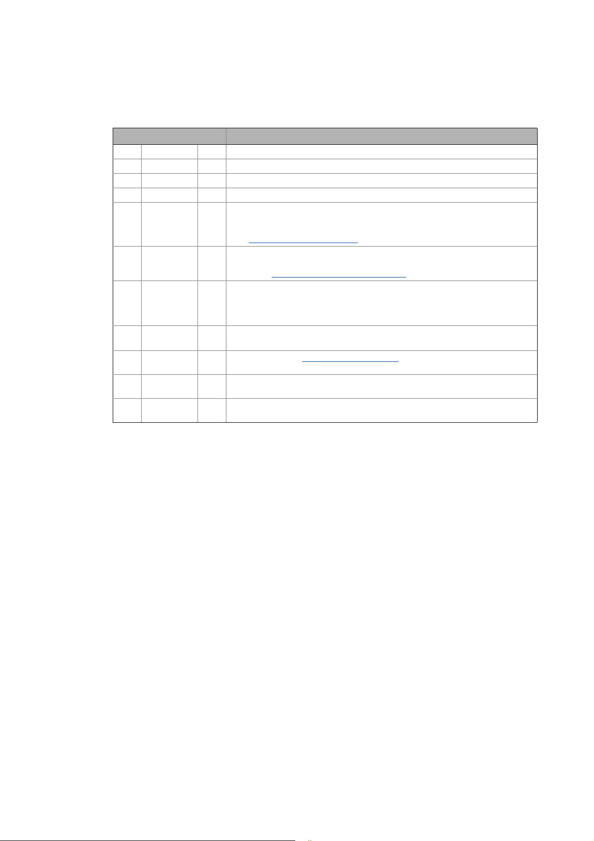
Documentation type Subject
System manuals System overview/sample topologies
Communication manuals
Online helps
Reference manuals
Online helps
Software manuals
Online helps
® bus system as part of the Lenze automation system "Controller-based Automation".
• Controller-based Automation
• Visualising
Bus systems
• Controller-based Automation EtherCAT®
• Controller-based Automation CANopen®
• Controller-based Automation PROFIBUS®
• Controller-based Automation PROFINET®
Lenze Controller:
• Controller 3200 C
• Controller c300
• Controller p300
• Controller p500
Lenze Engineering Tools:
• »PLC Designer«: Programming
• »Engineer«: Inverter configuration
• »VisiWinNET® Smart«: Visualisation
• »Backup & Restore«: Back up/restore data
6 Lenze · Controller-based Automation · EtherCAT® Communication Manual · DMS 6.4 EN · 04/2014 · TD17
Page 7
1 About this documentation
_ _ _ _ _ _ _ _ _ _ _ _ _ _ _ _ _ _ _ _ _ _ _ _ _ _ _ _ _ _ _ _ _ _ _ _ _ _ _ _ _ _ _ _ _ _ _ _ _ _ _ _ _ _ _ _ _ _ _ _ _ _ _ _
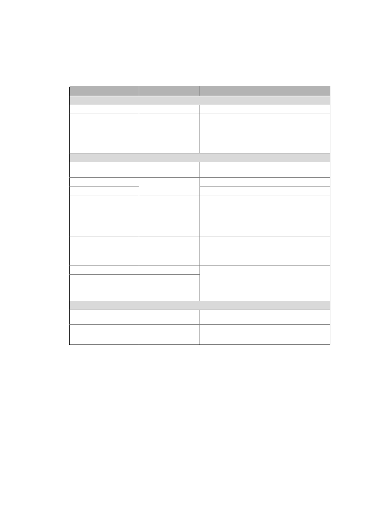
More technical documentation for Lenze components
Further information on Lenze products which can be used in conjunction with Controller-based
Automation can be found in the following sets of documentation:
Mounting & wiring Symbols:
Mounting instructions
• Controller
• Communication cards (MC-xxx)
• I/O system 1000 (EPM-Sxxx)
• Inverter, Servo Drives
•Communication modules
Operating instructions
• Controller
• Servo system ECS (ECSxE, ECSxM)
Sample applications/Using application templates
Online help/software manuals
• Application Sample i700
• Application Samples
• ApplicationTemplate
Parameter setting, configuration, commissioning
Online help/reference manuals
•L-force Controller
• Inverter, Servo Drives
• I/O system 1000 (EPM-Sxxx)
Online help/communication manuals
• Bus systems
•Communication modules
Operating instructions
• Servo system ECS (ECSxE, ECSxM)
Printed documentation
Online help in the Lenze Engineering
Tool (also available as PDF file at
www.lenze.com
.)
Tip!
Current documentation and software updates with regard to Lenze products can be found
in the download area at:
www.lenze.com
Target group
This documentation is intended for persons who plan, install, commission and maintain the
networking of devices as part of the Lenze automation system "Controller-based Automation".
Information on validity
The information provided in this documentation is valid for the Lenze automation system
"Controller-based Automation" from version 3.
Screenshots/application examples
All screenshots in this documentation are application examples. Depending on the firmware
version of the field devices and the software version of the Engineering tools installed (e.g. »PLC
Designer« ), screenshots in this documentation may differ from the representation on the screen.
Lenze · Controller-based Automation · EtherCAT® Communication Manual · DMS 6.4 EN · 04/2014 · TD17 7
Page 8
1 About this documentation
1.1 Document history
_ _ _ _ _ _ _ _ _ _ _ _ _ _ _ _ _ _ _ _ _ _ _ _ _ _ _ _ _ _ _ _ _ _ _ _ _ _ _ _ _ _ _ _ _ _ _ _ _ _ _ _ _ _ _ _ _ _ _ _ _ _ _ _
1.1 Document history
Version Description
1.0 09/2008 TD17 First edition
2.0 05/2009 TD17 General revision
3.0 10/2009 TD17 General revision
4.0 10/2010 TD17 Commissioning and configuration with the Lenze »PLC Designer« V3.x
4.1 03/2011 TD17 • Special features for the ECS servo system added.
• References to Lenze sample projects for EtherCAT logic field devices (device
application + PLC program) added.
Commissioning of the system
4.2 12/2011 TD17 • Revision on the Lenze automation system"Controller-based Automation",
Release 3.2
•Chapter Function library L_IODrvEtherCAT.lib
5.0 08/2012 TD17 • Revision on the Lenze automation system"Controller-based Automation",
Release 3.3
• Information on the Servo-Inverter i700 added.
• Information on the ECS servo system and »GDC« removed.
6.0 11/2012 TD17 • General corrections
•New layout
6.1 12/2012 TD17 New function block L_ETC_GetEmergency (FB)
system "Controller-based Automation", Release 3.4
6.3 11/2013 TD17 Revision on the Lenze automation system"Controller-based Automation",
release 3.6
6.4 04/2014 TD17 Revision on the Lenze automation system"Controller-based Automation",
release 3.8
( 39)
( 110) updated.
( 141) in the Lenze automation
8
Lenze · Controller-based Automation · EtherCAT® Communication Manual · DMS 6.4 EN · 04/2014 · TD17
Page 9
1 About this documentation
1.2 Conventions used
_ _ _ _ _ _ _ _ _ _ _ _ _ _ _ _ _ _ _ _ _ _ _ _ _ _ _ _ _ _ _ _ _ _ _ _ _ _ _ _ _ _ _ _ _ _ _ _ _ _ _ _ _ _ _ _ _ _ _ _ _ _ _ _
1.2 Conventions used
This documentation uses the following conventions to distinguish different types of information:
Type of information Identification Examples/notes
Numbers
Decimal Normal spelling Example: 1234
Decimal separator Point In general, the decimal point is used.
Example: 1234.56
Hexadecimal 0x[0 ... 9, A ... F] Example: 0x60F4
Binary
• Nibble
Text
Program name » « PC software
Window italics The message window... / The Options dialog box ...
Variable name Setting bEnable to TRUE...
Control element Bold The OK button ... / The Copy command ... / The Properties
Sequence of menu
commands
Shortcut <Bold> Use <F1> to open the online help.
Program code Courier IF var1 < var2 THEN
Keyword Courier bold
Hyperlink Underlined
Icons
Page reference ( 9) Optically highlighted reference to another page. Can be
Step-by-step instructions
0b[0, 1] Example: ’0b0110’
Example: ’0b0110.0100’
Example: Lenze »Engineer«
tab ... / The Name input field ...
If several successive commands are required for
executing a function, the individual commands are
separated from each other by an arrow: Select the
command File
If a key combination is required for a command, a "+" is
placed between the key identifiers: With
<Shift>+<ESC>...
a = a + 1
END IF
Optically highlighted reference to another topic. Can be
activated with a mouse-click in this documentation.
activated with a mouse-click in this documentation.
Step-by-step instructions are marked by a pictograph.
Open to...
Lenze · Controller-based Automation · EtherCAT® Communication Manual · DMS 6.4 EN · 04/2014 · TD17 9
Page 10
1 About this documentation
1.3 Terminology used
_ _ _ _ _ _ _ _ _ _ _ _ _ _ _ _ _ _ _ _ _ _ _ _ _ _ _ _ _ _ _ _ _ _ _ _ _ _ _ _ _ _ _ _ _ _ _ _ _ _ _ _ _ _ _ _ _ _ _ _ _ _ _ _
1.3 Terminology used
Term Meaning
CAN CAN (Controller Area Network) is an asynchronous, serial fieldbus system.
CANopen® is a communication protocol based on CAN. The Lenze system bus (CAN on board)
operates with a subset of this communication protocol.
CANopen® is a registered Community Trade Mark of the CAN User Organisation CiA® (CAN
in Automation e. V.).
Code Parameter for parameterising or monitoring the field device. The term is also referred to as
CoE CANopen over EtherCAT
Controller The controller is the central component of the automation system which controls the Logic
DC Distributed clocks (distributed synchronised clocks)
Engineering PC The Engineering PC and the Engineering tools installed serve to configure and parameterise
Engineering tools Lenze software solutions for simply engineering in all phases:
FB Function block (contained in a function library)
Fieldbus stations Controller (PLC) and inverter integrated in the bus system (EtherCAT)
Field device
FoE File Access over EtherCAT
FUN Function (contained in a function library)
Index Each object has a unique index for addressing purposes.
Inverter Generic term for Lenze frequency inverters, servo inverters
PLC Programmable Logic Controller
Object "Container" for one or more parameters with which you can parameterise or monitor the
"index" in common usage.
and Motion functionalities (by means of the runtime software).
The controller communicates with the field devices via the fieldbus.
the system.
The Engineering PC communicates with the controller via Ethernet.
•»EASY Starter«
• »Engineer«
•»PLC Designer«
•»WebConfig«
•»VisiWinNET®«
•»IPC Backup & Restore«
Lenze Engineering tools
EtherCAT® (Ethernet for Controller and Automation Technology) is an Ethernet-based
fieldbus system which meets the application profile for industrial real-time systems.
EtherCAT® is a registered trademark and patented technology, licensed by Beckhoff
Automation GmbH, Germany.
In this documentation, the index is shown as a hexadecimal value preceded by "0x", e.g.
"0x1000".
(German designation: SPS - Speicherprogrammierbare Steuerung)
PROFIBUS® (Process Fieldbus) is a common fieldbus system for the automation of machines
and production lines.
PROFIBUS® is a registered trademark and patented technology licensed by the PROFIBUS &
PROFINET International user organisation (PI).
PROFINET® (Process Field Network) is a real-time capable fieldbus system based on Ethernet.
PROFINET® is a registered trademark and patented technology licensed by the PROFIBUS &
PROFINET International (PI) user organisation.
fieldbus node.
( 29)
10
Lenze · Controller-based Automation · EtherCAT® Communication Manual · DMS 6.4 EN · 04/2014 · TD17
Page 11

1 About this documentation
1.3 Terminology used
_ _ _ _ _ _ _ _ _ _ _ _ _ _ _ _ _ _ _ _ _ _ _ _ _ _ _ _ _ _ _ _ _ _ _ _ _ _ _ _ _ _ _ _ _ _ _ _ _ _ _ _ _ _ _ _ _ _ _ _ _ _ _ _
Term Meaning
Subcode If a code contains several parameters, they are stored in so-called "subcodes".
This manual uses a slash "/" as a separator between code and subcode (e.g. "C00118/3").
In normal usage, the term is also referred to as "Subindex".
Subindex If a code contains several parameters, they are stored in so-called "subindices".
In this documentation, the slash "/" is used as a separator between an index and subindex,
e.g. "0x1018/1".
Lenze · Controller-based Automation · EtherCAT® Communication Manual · DMS 6.4 EN · 04/2014 · TD17 11
Page 12
1 About this documentation
1.4 Definition of the notes used
_ _ _ _ _ _ _ _ _ _ _ _ _ _ _ _ _ _ _ _ _ _ _ _ _ _ _ _ _ _ _ _ _ _ _ _ _ _ _ _ _ _ _ _ _ _ _ _ _ _ _ _ _ _ _ _ _ _ _ _ _ _ _ _
1.4 Definition of the notes used
The following signal words and symbols are used in this documentation to indicate dangers and
important information:
Safety instructions
Layout of the safety instructions:
Pictograph and signal word!
(characterises the type and severity of danger)
Note
(describes the danger and suggests how to prevent dangerous situations)
Pictograph Signal word Meaning
Danger! Danger of personal injury through dangerous electrical voltage
Danger! Danger of personal injury through a general source of danger
Stop! Danger of damage to material assets
Refere nce to a n imm inent d ange r that m ay resu lt in deat h or s erious person al injury
if the corresponding measures are not taken.
Refere nce to a n imm inent d ange r that m ay resu lt in deat h or s erious person al injury
if the corresponding measures are not taken.
Reference to a possible danger that may result in damage to material assets if the
corresponding measures are not taken.
Application notes
Pictograph Signal word Meaning
Note! Important note to ensure trouble-free operation
Tip! Useful tip for easy handling
Reference to other documentation
12
Lenze · Controller-based Automation · EtherCAT® Communication Manual · DMS 6.4 EN · 04/2014 · TD17
Page 13

2 Safety instructions
_ _ _ _ _ _ _ _ _ _ _ _ _ _ _ _ _ _ _ _ _ _ _ _ _ _ _ _ _ _ _ _ _ _ _ _ _ _ _ _ _ _ _ _ _ _ _ _ _ _ _ _ _ _ _ _ _ _ _ _ _ _ _ _
2 Safety instructions
Observe the following safety instructions if you want to commission an inverter or a system with
the Lenze Controller.
Read the documentation supplied with the system components carefully before you
start commissioning the devices and the Lenze Controller!
The system manual contains safety instructions which must be observed!
Danger!
Risk of injury
There is risk of injury by ...
• unpredictable motor movements (e.g. an unintended direction of rotation, too high
speeds, or jerky movement);
• impermissible operating states during the parameterisation while there is an active
online connection to the device.
Possible consequences
Death or severe injuries
Protective measures
• If required, provide systems with installed inverters with additional monitoring and
protective devices according to the safety regulations valid in each case (e.g. law on
technical equipment, regulations for the prevention of accidents).
• During commissioning, maintain an adequate safety distance to the motor or the
machine parts driven by the motor.
Stop!
Damage or destruction of machine parts
Damage or destruction of machine parts can be caused by ...
• unpredictable motor movements (e.g. an unintended direction of rotation, too high
speeds, or jerky movement);
• impermissible operating states during the parameterisation while there is an active
online connection to the device.
Possible consequences
Damage or destruction of machine parts
Protective measures
If required, provide systems with installed inverters with additional monitoring and
protective devices according to the safety regulations valid in each case (e.g. law on
technical equipment, regulations for the prevention of accidents).
Lenze · Controller-based Automation · EtherCAT® Communication Manual · DMS 6.4 EN · 04/2014 · TD17 13
Page 14
3 Controller-based Automation: Central motion control
_ _ _ _ _ _ _ _ _ _ _ _ _ _ _ _ _ _ _ _ _ _ _ _ _ _ _ _ _ _ _ _ _ _ _ _ _ _ _ _ _ _ _ _ _ _ _ _ _ _ _ _ _ _ _ _ _ _ _ _ _ _ _ _
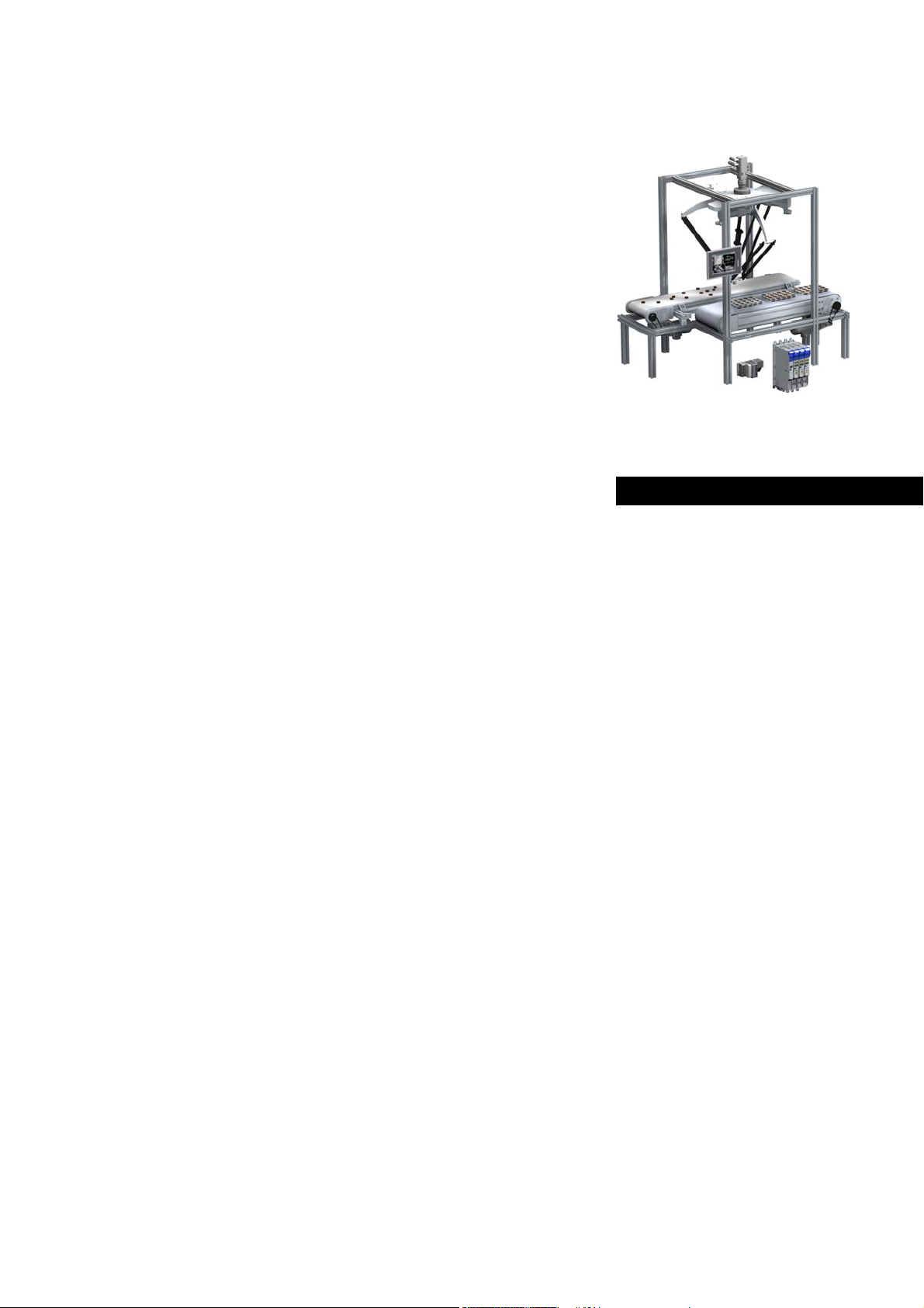
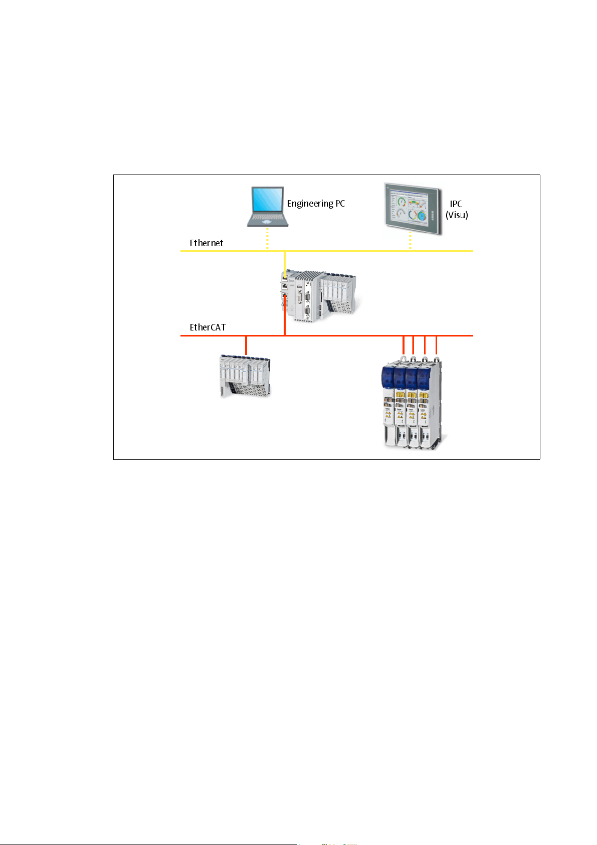
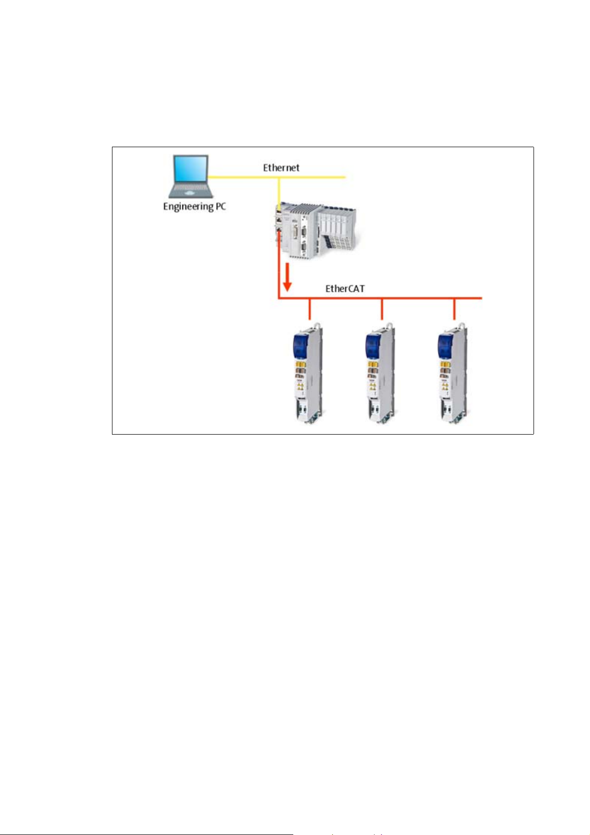
3 Controller-based Automation: Central motion control
The Lenze automation system "Controller-based Automation" serves to create complex automation
solutions with central motion control. Here, the Controller is the control centre of the system.
System structure of the Controller-based Automation: "All from one single source"
[3-1] Example: EtherCAT bus system with a 3231 C controller, a 1000 I/O system and an i700 servo inverter
14 Lenze · Controller-based Automation · EtherCAT® Communication Manual · DMS 6.4 EN · 04/2014 · TD17
Page 15

3 Controller-based Automation: Central motion control
_ _ _ _ _ _ _ _ _ _ _ _ _ _ _ _ _ _ _ _ _ _ _ _ _ _ _ _ _ _ _ _ _ _ _ _ _ _ _ _ _ _ _ _ _ _ _ _ _ _ _ _ _ _ _ _ _ _ _ _ _ _ _ _
Lenze provides especially coordinated system components:
• Engineering software
The Lenze Engineering tools
to parameterise, configure and diagnose the system. The Engineering PC communicates with
the Controller via Ethernet.
•Controller
The Lenze Controller is available as Panel Controller with integrated touch display and as
Cabinet Controller in control cabinet design.
Cabinet Controllers provide a direct coupling of the I/O system 100 via the integrated backplane
bus.
The runtime software of the Lenze Controllers provides the control and/or visualisation of
motion sequences. The following software versions are available:
• "Logic": Sequence control in the Controller, motion control in the inverter
• "Motion": Sequence control and motion control in the Controller, inverter as actuating drive
• "Visu": Optional visualisation of the automation system, can be used separately or in addition
to "Logic" or "Motion"
An external monitor panel/display can be connected to the Cabinet Controller 3231 C/
3241 C.
• Without software: Controller as single component with operating system only
•Bus systems
EtherCAT is a standard "on board" bus system of the Controller-based Automation. EtherCAT
enables the control of all nodes (Motion/Logic) on one common fieldbus.
Optionally, CANopen, PROFIBUS and PROFINET can be used as extended topologies.
The Controllers c300/p300 have a CANopen interface "on board" as well (in addition to
EtherCAT).
• Inverter (e.g. Servo Inverter i700)
( 29) on your Engineering PC (Windows operating system ) serve
"Logic & Motion" runtime software
The "Controller-based Automation" system allows for the central control of devices for Logic and
Motion applications. The runtime software runs on the Controller.
In case of Logic applications, the sequence control is carried out in the Controller and the motion
control is carried out in the inverter.
In case of Motion applications , the sequence control and motion control are carried out in the
Controller. The inverter is used as actuating drive.
• Motion applications make special demands on the cycle time and real-time capability of the bus
system between the Controller and the subordinate fieldbus nodes.
• this is for instance the case if the field devices, for example, are to move in a synchronised way
or if position setpoints are to be transmitted.
Lenze · Controller-based Automation · EtherCAT® Communication Manual · DMS 6.4 EN · 04/2014 · TD17 15
Page 16
3 Controller-based Automation: Central motion control
_ _ _ _ _ _ _ _ _ _ _ _ _ _ _ _ _ _ _ _ _ _ _ _ _ _ _ _ _ _ _ _ _ _ _ _ _ _ _ _ _ _ _ _ _ _ _ _ _ _ _ _ _ _ _ _ _ _ _ _ _ _ _ _
Fieldbus communication
The Lenze Controllers have different interfaces for fieldbus communication:
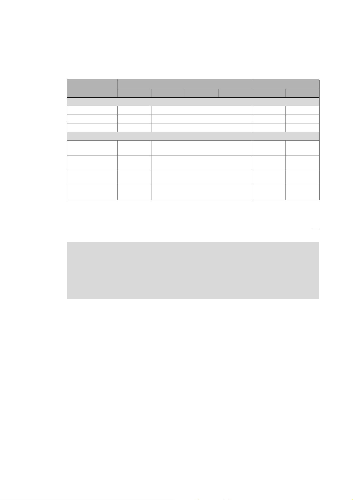
Area Cabinet Controller Panel Controller
c300 3221 C 3231 C 3241 C p300 p500
Interfaces (on board)
Ethernet1212
EtherCAT 1
CANopen 1
Optional interfaces (communication cards)
CANopen
MC-CAN2
PROFIBUS master
MC-PBM
PROFIBUS slave
MC-PBS
PROFINET device
MC-PND
1)
2)
- -
- -
- -
- -
11
-1
1)
2)
1
-
1) In preparation
2) Only the CAN master functionality is supported.
The Ethernet interface serves to connect the Engineering PC or to create line topologies (no
integrated switch for Controller c300/p300).
More information on the bus systems and configuration can be found in the
communication manuals:
• Controller-based Automation EtherCAT®
• Controller-based Automation CANopen®
• Controller-based Automation PROFIBUS®
• Controller-based Automation PROFINET®
16 Lenze · Controller-based Automation · EtherCAT® Communication Manual · DMS 6.4 EN · 04/2014 · TD17
Page 17

4 The Lenze automation system with EtherCAT
4.1 Brief description of EtherCAT
_ _ _ _ _ _ _ _ _ _ _ _ _ _ _ _ _ _ _ _ _ _ _ _ _ _ _ _ _ _ _ _ _ _ _ _ _ _ _ _ _ _ _ _ _ _ _ _ _ _ _ _ _ _ _ _ _ _ _ _ _ _ _ _
4 The Lenze automation system with EtherCAT
This chapter provides basic information about ...
• the structure of the Lenze automation system using the EtherCAT bus system;
• the Lenze Engineering tools required for commissioning;
• the interaction of the components.
4.1 Brief description of EtherCAT
Tip!
Detailed information on EtherCAT is provided on the Internet website of the EtherCAT
Technology Group:
www.ethercat.org
Product features
• EtherCAT is a high-performance bus system based on Ethernet.
• Due to its integrated synchronisation mechanisms based on "distributed clocks", EtherCAT
possesses outstanding real time characteristics.
Synchronisation with "Distributed clocks" (DC)
• EtherCAT provides a higher bandwidth compared to CANopen:
• This enables motion and logic applications to be operated by the same fieldbus.
• The number of the nodes to be controlled is higher.
• The maximally possible bus length is longer.
• EtherCAT can access all field devices via a common interface. Therefore, unlike for the Lenze
CANopen control technology, a division into Logic bus and Motion bus is not required.
• The "Modular Device Profile for IPC" (MDP) is based on the "Modular Device Profile Specification"
of the EtherCAT Technology Group. All (software and hardware) components of the Lenze
Controller or Embedded PC are divided into modules. The list of the modules available is
generated dynamically, depending on the physically available components. The Lenze I/O
system 1000 with the EPM-S130 head end supports the "Modular Device Profile".
( 36)
Lenze · Controller-based Automation · EtherCAT® Communication Manual · DMS 6.4 EN · 04/2014 · TD17 17
Page 18
4 The Lenze automation system with EtherCAT
4.1 Brief description of EtherCAT
_ _ _ _ _ _ _ _ _ _ _ _ _ _ _ _ _ _ _ _ _ _ _ _ _ _ _ _ _ _ _ _ _ _ _ _ _ _ _ _ _ _ _ _ _ _ _ _ _ _ _ _ _ _ _ _ _ _ _ _ _ _ _ _
4.1.1 Structure of the EtherCAT bus system
Basic structure
[4-1] Example: EtherCAT bus system with 3231 C controller and i700 servo inverter
Physical structure
An EtherCAT master can communicate with one or more nodes (slaves).
Internally, the EtherCAT bus has a ring topology. Since Ethernet cables are provided with a feed
conductor and a return conductor within one cable, for the installer the topology seems to be a line.
The last slave closes the ring.
Switches, hubs, or other infrastructure components known from the Ethernet standard must not be
used because they impair the real-time performance.
18
Lenze · Controller-based Automation · EtherCAT® Communication Manual · DMS 6.4 EN · 04/2014 · TD17
Page 19

4 The Lenze automation system with EtherCAT
4.1 Brief description of EtherCAT
_ _ _ _ _ _ _ _ _ _ _ _ _ _ _ _ _ _ _ _ _ _ _ _ _ _ _ _ _ _ _ _ _ _ _ _ _ _ _ _ _ _ _ _ _ _ _ _ _ _ _ _ _ _ _ _ _ _ _ _ _ _ _ _
4.1.2 Communication
Compared with conventional Ethernet, the collision-free transfer of telegrams on the fieldbus
makes EtherCAT a real-time capable bus system.
Communication is always initiated by the EtherCAT master, i.e. the Lenze Controller. A telegram
sent by the master passes through all EtherCAT slaves. The last slave of the communication chain
sends the telegram back to the EtherCAT master. On the way back, the telegram is directly sent to
the EtherCAT master, without being processed in the slaves.
When EtherCAT is used, data are transferred in so-called "EtherCAT frames". The fieldbus nodes
only remove the data intended for them and do so while the EtherCAT frame is passing through the
device. Output data are inserted into the frame at the same time. Read and write access is always
carried out on a small section of the overall EtherCAT frame – the datagrams. This means that a
frame does not have to be received completely before it is processed. Each datagram is passed on
with minimal delay.
Lenze · Controller-based Automation · EtherCAT® Communication Manual · DMS 6.4 EN · 04/2014 · TD17 19
Page 20
4 The Lenze automation system with EtherCAT
Operational
Pre-Operational
Init
Safe-Operational
4.1 Brief description of EtherCAT
_ _ _ _ _ _ _ _ _ _ _ _ _ _ _ _ _ _ _ _ _ _ _ _ _ _ _ _ _ _ _ _ _ _ _ _ _ _ _ _ _ _ _ _ _ _ _ _ _ _ _ _ _ _ _ _ _ _ _ _ _ _ _ _
4.1.2.1 The EtherCAT state machine
Before communication via EtherCAT is possible, the fieldbus is scanned by the EtherCAT state
machine when the installation is being powered up. The following illustration shows the possible
status changes from the point of view of an EtherCAT slave.
E94AYCET009
[4-2] EtherCAT state machine
State Description
Init • Initialisation phase
• No SDO/PDO communication with the slaves
• Device can be detected by fieldbus scan
Pre-operational • The fieldbus is active.
• SDO communication (mailbox communication) is possible.
• No PDO communication
Safe-operational • SDO communication (mailbox communication) is possible.
• PDO communication:
• The input data in the process image are updated.
• The output data from the process image are not transferred to the slaves.
Operational Normal operation
• SDO communication
• PDO communication
• Fieldbus synchronisation has been successful (if used)
Note!
• A fieldbus scan is possible in any EtherCAT state.
Determining the physical EtherCAT configuration (fieldbus scan)
• The SDO communication via the EtherCAT bus is only possible if at least the "PreOperational" state has been reached.
• Only in the transitional phases between states can bus nodes be in different states.
( 75)
20
Lenze · Controller-based Automation · EtherCAT® Communication Manual · DMS 6.4 EN · 04/2014 · TD17
Page 21

4 The Lenze automation system with EtherCAT
4.1 Brief description of EtherCAT
_ _ _ _ _ _ _ _ _ _ _ _ _ _ _ _ _ _ _ _ _ _ _ _ _ _ _ _ _ _ _ _ _ _ _ _ _ _ _ _ _ _ _ _ _ _ _ _ _ _ _ _ _ _ _ _ _ _ _ _ _ _ _ _
AL Status Code
Possible errors during transitions between states are entered in the EtherCAT register "AL Status
Code" (address 0x0134:0x0135).
AL Status Code
[hex]
0x0000 No error
0x0011 Invalid status change requested
0x0012 Unknown status requested
0x0013 "Bootstrap" status is not supported
0x0016 Invalid mailbox configuration "Pre-operational"
0x001A Synchronisation error
0x001B Sync manager watchdog
0x001D Invalid output data configuration
0x001E Invalid input data configuration
0x002B Invalid input and output data
0x0030 Invalid configuration of DC synchronisation
0x9001 Firmware watchdog error
0x9002 Mapping error
Description
Lenze · Controller-based Automation · EtherCAT® Communication Manual · DMS 6.4 EN · 04/2014 · TD17 21
Page 22

4 The Lenze automation system with EtherCAT
4.1 Brief description of EtherCAT
_ _ _ _ _ _ _ _ _ _ _ _ _ _ _ _ _ _ _ _ _ _ _ _ _ _ _ _ _ _ _ _ _ _ _ _ _ _ _ _ _ _ _ _ _ _ _ _ _ _ _ _ _ _ _ _ _ _ _ _ _ _ _ _
4.1.2.2 Addressing of the slaves
The EtherCAT system uses two types of addressing for the slaves:
Auto-increment addressing
The auto-increment addressing is used by the master during the initialisation phase of the fieldbus.
When the "Pre-Operational" state has been reached, the master uses the Fixed-Address addressing.
Fixed-address addressing
With the fixed-address addressing, the slaves are addressed via the station address distributed by
the master during the start-up phase.
In the EtherCAT bus topology in »PLC Designer«, the first slave is given the address ’1001’, the
second the address ’1002’ and so on. The EtherCAT addresses cannot be changed.
The EtherCAT address of the master is ’0’. Access to master objects with the address ’0’ is possible.
Example
The first slave of a configuration is given the following addresses ...
• ’0’ due to the automatic incrementation procedure;
• ’1001’ due to the fixed addressing procedure.
22
Lenze · Controller-based Automation · EtherCAT® Communication Manual · DMS 6.4 EN · 04/2014 · TD17
Page 23

4 The Lenze automation system with EtherCAT
4.1 Brief description of EtherCAT
_ _ _ _ _ _ _ _ _ _ _ _ _ _ _ _ _ _ _ _ _ _ _ _ _ _ _ _ _ _ _ _ _ _ _ _ _ _ _ _ _ _ _ _ _ _ _ _ _ _ _ _ _ _ _ _ _ _ _ _ _ _ _ _
4.1.2.3 Working counter
Each EtherCAT datagram contains a working counter (WKC) which is incremented by each slave
after the data have been processed successfully.
The working counter (WKC) can be used as a diagnostics option to check the processing of the
EtherCAT telegrams by the slaves.
In each cycle, the Lenze Controller compares the expected value of the working counter with the
value read back via the fieldbus. If the read-back value is smaller than the expected value, not all
addressed slaves have been reached. The controller detects this and reports an error.
Messages: WKC Error / Not all slaves "Operational" / SyncManager Watchdog
Example
• 10 slaves read/write process data in the "Operational" state
Expected value of the WKC: 10
• A cable break between the 8th and 9th slave causes the master to be unable to access slave 9
and slave 10:
• Value of the restored WKC: 8
• An error response is initiated in the Lenze Controller.
• The EtherCAT bus changes to the state "Pre-Operational".
( 177)
Lenze · Controller-based Automation · EtherCAT® Communication Manual · DMS 6.4 EN · 04/2014 · TD17 23
Page 24
4 The Lenze automation system with EtherCAT
4.2 Required hardware components
_ _ _ _ _ _ _ _ _ _ _ _ _ _ _ _ _ _ _ _ _ _ _ _ _ _ _ _ _ _ _ _ _ _ _ _ _ _ _ _ _ _ _ _ _ _ _ _ _ _ _ _ _ _ _ _ _ _ _ _ _ _ _ _
4.2 Required hardware components
4.2.1 Field devices
The Lenze automation system supports the following EtherCAT-capable logic and motion
components:
Field devices EtherCAT
Logic Motion
Controller Controller 32xx C
Controller c300
Controller p300
Controller p500
i700 servo inverter Single axis
Double axis
Servo Drives 9400 1) HighLine
Highline with CiA402
PLC
Regenerative power supply
module
Inverter Drives 8400 2) StateLine
HighLine
TopLine
I/O-System 1000 EPM-Sxxx
1) With EtherCAT E94AYCET communication module
2) With EtherCAT E84AYCET communication module
Field devices of other manufacturers can be integrated as Logic nodes if they provide a standardcompliant EtherCAT device description.
24
Lenze · Controller-based Automation · EtherCAT® Communication Manual · DMS 6.4 EN · 04/2014 · TD17
Page 25
4 The Lenze automation system with EtherCAT
4.2 Required hardware components
_ _ _ _ _ _ _ _ _ _ _ _ _ _ _ _ _ _ _ _ _ _ _ _ _ _ _ _ _ _ _ _ _ _ _ _ _ _ _ _ _ _ _ _ _ _ _ _ _ _ _ _ _ _ _ _ _ _ _ _ _ _ _ _
4.2.2 The Lenze Controller - the central component
[4-3] Example: EtherCAT bus system with 3231 C controller as gateway and i700 servo inverter
The Lenze Controller is the central component in the EtherCAT bus system:
• The controller is the EtherCAT master.
• The Lenze Controllers have an EtherCAT interface "on-board".
• The controller acts as an EtherCAT gateway in order to enable access to the field devices from
the Engineering PC via Ethernet and EtherCAT.
• The devices are interconnected successively in line. For correct operation, it is nec essary that th e
physical sequence of the EtherCAT field devices matches the bus topology created in »PLC
Designer«.
Otherwise the system will not become "Operational". (An error message indicates which slave
(product code) is expected at what position.)
• Each EtherCAT slave has two EtherCAT ports.
In contrast to Ethernet, one port is assigned as input, the other one as output.
The inputs (IN) and outputs (OUT) must be correctly wired to each other
• A bus termination at the last slave is not required since the bus system at the last slave is
terminated automatically.
Lenze · Controller-based Automation · EtherCAT® Communication Manual · DMS 6.4 EN · 04/2014 · TD17 25
Page 26
4 The Lenze automation system with EtherCAT
4.2 Required hardware components
_ _ _ _ _ _ _ _ _ _ _ _ _ _ _ _ _ _ _ _ _ _ _ _ _ _ _ _ _ _ _ _ _ _ _ _ _ _ _ _ _ _ _ _ _ _ _ _ _ _ _ _ _ _ _ _ _ _ _ _ _ _ _ _
4.2.3 EtherCAT product codes
Device descriptions can be assigned to the corresponding devices with the help of the product
codes. In »PLC Designer«, you can install device descriptions with the menu command Tools
Device repository....
Importing missing devices / device description files
Structure of the device ID: <Manufacturer ID>_<Productcode><Revision number
Identification Meaning
Manufacturer ID Unique identification for the manufacturer, for Lenze devices: 0x3B
Product code Product code of the product range/the device
Revision number Revision number
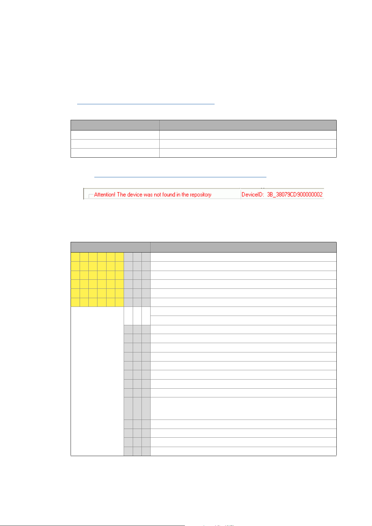
If, for instance, a device available at the fieldbus without an installed device description is detected
during a Determining the physical EtherCAT configuration (fieldbus scan)
device ID as hexadecimal value is displayed:
( 78)
(59)
( 75) a message with the
In this example, the device description for a Lenze Servo Drive 9400 HighLine, actuating drive speed, is not installed (0x38079CD9 = 940023001).
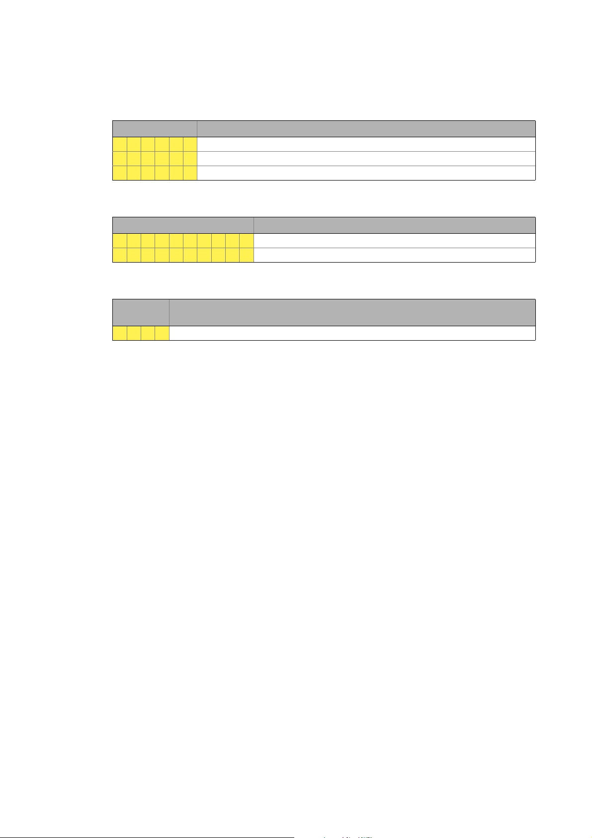
Product codes for Servo Drives 9400
Product code [dec] Meaning
9 4 0 0 2 1 x x x Servo Drive 9400 in general
9 4 0 0 2 2 x x x Servo Drive 9400 StateLine
9 4 0 0 2 3 x x x Servo Drive 9400 HighLine
9 4 0 0 2 4 x x x Servo Drive 9400 TopLine
9 4 0 0 2 5 x x x Servo Drive 9400 PLC
9 4 0 0 2 6 x x x Servo Drive 9400 V/R (regenerative power supply module)
Applications:
0 0 0 Empty application
0 0 1 Actuating drive - speed
0 0 2 Actuating drive - torque
0 0 3 Electronic gearbox
0 0 4 Synchronism with mark synchronisation
0 0 5 Table positioning
0 0 6 Positioning sequence control
0 0 7 PLC application
000
89Reserved
...
...
9
Reserved
1 x x Reserved for device profiles
1 0 1 CiA402
2 x x Reserved for Lenze applications
2 0 1 Regenerative power supply module application
26
Lenze · Controller-based Automation · EtherCAT® Communication Manual · DMS 6.4 EN · 04/2014 · TD17
Page 27
4 The Lenze automation system with EtherCAT
4.2 Required hardware components
_ _ _ _ _ _ _ _ _ _ _ _ _ _ _ _ _ _ _ _ _ _ _ _ _ _ _ _ _ _ _ _ _ _ _ _ _ _ _ _ _ _ _ _ _ _ _ _ _ _ _ _ _ _ _ _ _ _ _ _ _ _ _ _
Product codes for Inverter Drives 8400
Product code [dec] Meaning
8 4 0 0 2 2 Inverter Drive 8400 StateLine
8 4 0 0 2 3 Inverter Drive 8400 HighLine
8 4 0 0 2 4 Inverter Drive 8400 TopLine
Product codes for i700 servo inverter
Product code [hex] Meaning
1 7 6 2 0 6 6 4 3 3 Single axis
1 7 6 2 0 6 6 4 3 4Double axis
Product codes for the I/O system 1000
Product code
[dec]
1 3 0 0 I/O system EPM-S130
Meaning
Lenze · Controller-based Automation · EtherCAT® Communication Manual · DMS 6.4 EN · 04/2014 · TD17 27
Page 28
4 The Lenze automation system with EtherCAT
4.2 Required hardware components
_ _ _ _ _ _ _ _ _ _ _ _ _ _ _ _ _ _ _ _ _ _ _ _ _ _ _ _ _ _ _ _ _ _ _ _ _ _ _ _ _ _ _ _ _ _ _ _ _ _ _ _ _ _ _ _ _ _ _ _ _ _ _ _
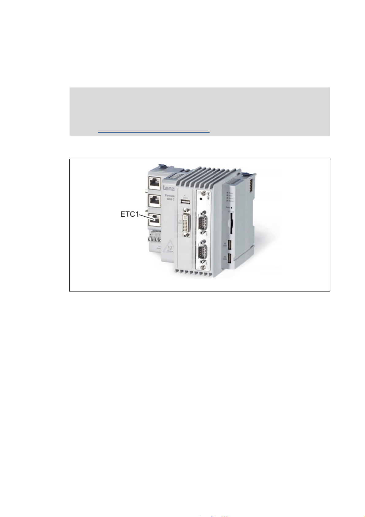
4.2.4 The EtherCAT interface of the Lenze Controller
The EtherCAT interface links the controller to an EtherCAT network.
Note!
In the case of a correct connection to the field devices, the LEDs of the EtherCAT interface
are lit.
EtherCAT interface of the Lenze Controller
Example
( 34)
ETC1: EtherCAT network connection
[4-4] EtherCAT interface at the 3231 C controller
28
Lenze · Controller-based Automation · EtherCAT® Communication Manual · DMS 6.4 EN · 04/2014 · TD17
Page 29
4 The Lenze automation system with EtherCAT
4.3 Lenze Engineering tools
_ _ _ _ _ _ _ _ _ _ _ _ _ _ _ _ _ _ _ _ _ _ _ _ _ _ _ _ _ _ _ _ _ _ _ _ _ _ _ _ _ _ _ _ _ _ _ _ _ _ _ _ _ _ _ _ _ _ _ _ _ _ _ _
4.3 Lenze Engineering tools
The Lenze Engineering tools enable the configuration and operation of controller-based Lenze
automation systems according to individual requirements.
Use the corresponding Engineering tool applicable to the field device.
»EASY Navigator«: Starting the suitable Engineering tool
The Lenze Engineering software consists of the Engineering tools optimised for the respective
Engineering stage.
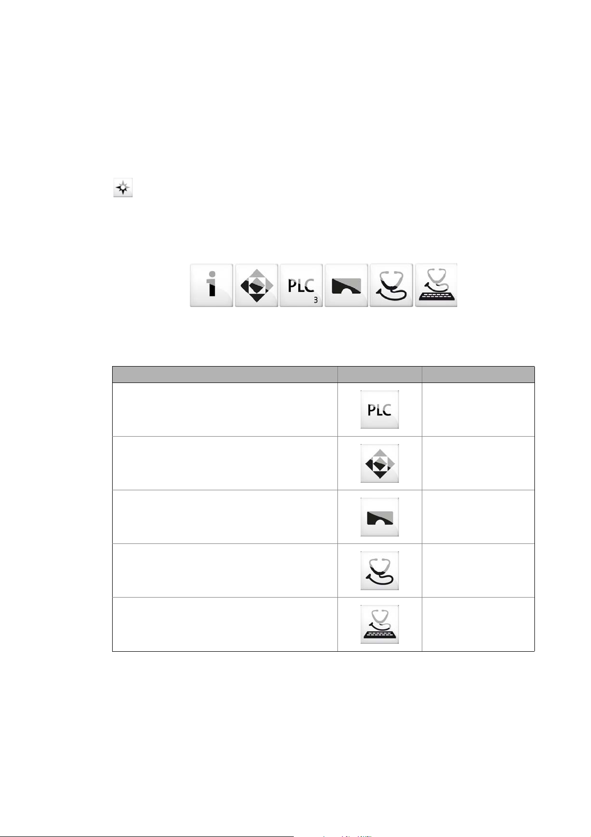
The »EASY Navigator« represents the Lenze Engineering tools installed on the Engineering PC. Start
the desired Engineering tool via the corresponding button:
The »EASY Navigator« ...
• simplifies orientation for selecting the suitable Engineering tool;
• allows for the simple start of the required Engineering tool (depending on the application):
What would you like to do? Button Engineering tool
Programming
• Program the controller
• Parameterise/commission the Servo-Inverter i700
• Parameterise the I/O system 1000
Parameterising/configuring the inverter
• Parameterising and configuring the automation/drive
system
• Parameterising Inverter Drives 8400/Servo Drives 9400
Visualising
• Visualising the applications of the automation system
• Creating the visualisation/user interfaces
Online diagnostics
• Easy online diagnostics of the controllers (from »EASY
Starter« V1.2) and other Lenze devices
Online parameterisation
• Online parameterisation/commissioning of Lenze
devices
• Direct online parameterisation when the online
connection to the Lenze devices is active.
»PLC Designer«
»Engineer«
»VisiWinNET«
»EASY Starter«
(reading parameters)
»EASY Starter«
(reading/writing
parameters)
Further Engineering tools that are not called via the »EASY Navigator« are:
• »WebConfig« (web-based parameterisation, configuration, and online diagnostics)
• »Backup & Restore« (data backup/recovery, software update).
Lenze · Controller-based Automation · EtherCAT® Communication Manual · DMS 6.4 EN · 04/2014 · TD17 29
Page 30
4 The Lenze automation system with EtherCAT
4.4 Interaction of the components
_ _ _ _ _ _ _ _ _ _ _ _ _ _ _ _ _ _ _ _ _ _ _ _ _ _ _ _ _ _ _ _ _ _ _ _ _ _ _ _ _ _ _ _ _ _ _ _ _ _ _ _ _ _ _ _ _ _ _ _ _ _ _ _
4.4 Interaction of the components
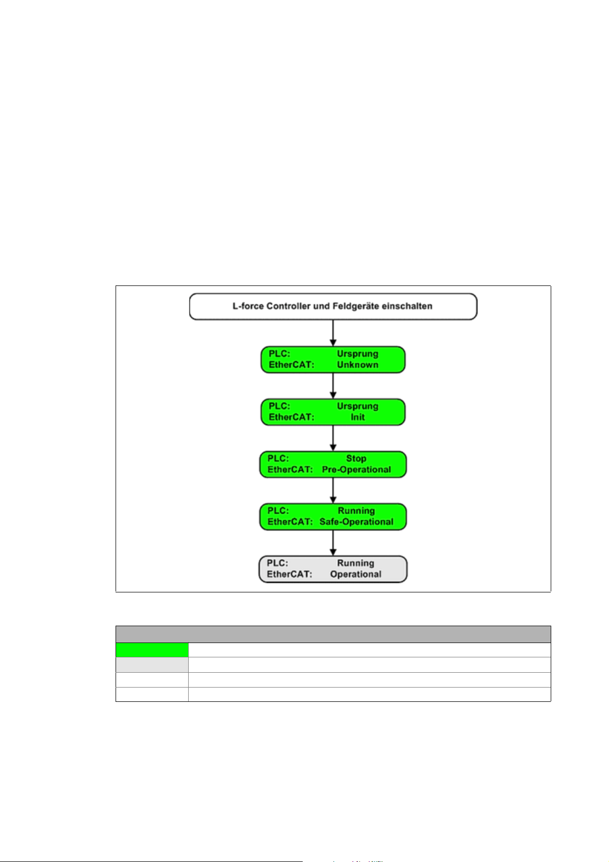
4.4.1 The state machine of the Lenze control technology
In the Lenze control technology, the states of the PLC and the EtherCAT bus are coupled. The PLC
controls the fieldbus.
After switch-on, the system automatically powers up if the following conditions are fulfilled:
• There is an executable PLC boot project on the controller (»PLC Designer« project).
• The slaves that are on the fieldbus and have been configured in »PLC Designer« are accessible.
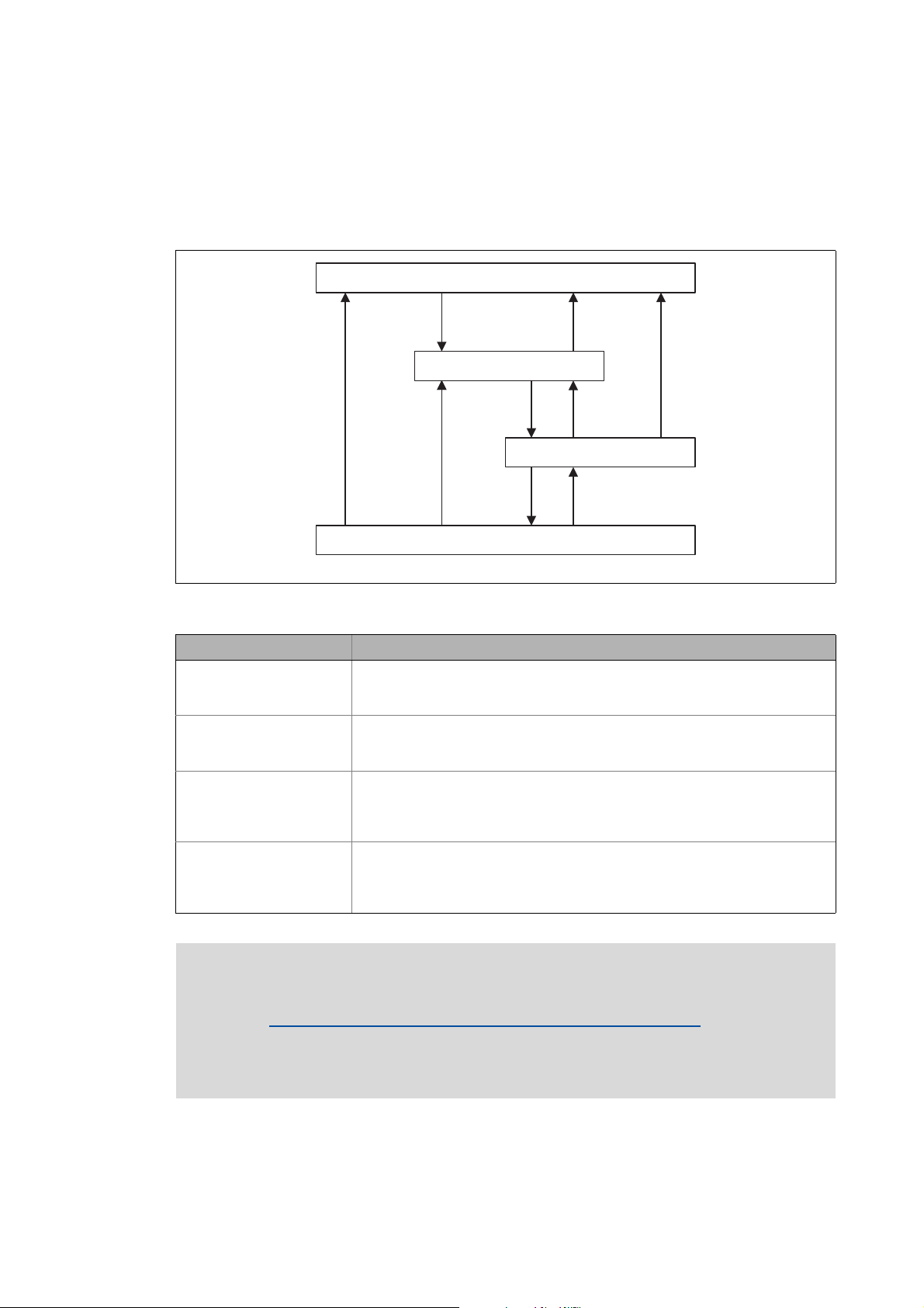
The following illustration shows the linkage of the states in the state machine of the Lenze control
technology when the conditions for the automatic acceleration of the system are fulfilled (boot
project with EtherCAT configuration):
[4-5] States in the Lenze control technology
Legend
Transitional state, automatic change to next state
Stationary state, change to next state by external actions
PLC State of the PLC
EtherCAT State of the EtherCAT bus
30
Lenze · Controller-based Automation · EtherCAT® Communication Manual · DMS 6.4 EN · 04/2014 · TD17
Page 31

4 The Lenze automation system with EtherCAT
4.4 Interaction of the components
_ _ _ _ _ _ _ _ _ _ _ _ _ _ _ _ _ _ _ _ _ _ _ _ _ _ _ _ _ _ _ _ _ _ _ _ _ _ _ _ _ _ _ _ _ _ _ _ _ _ _ _ _ _ _ _ _ _ _ _ _ _ _ _
Explanation of the transitions during system start
While a state is passed through, different tests are carried out (e.g. it is tested whether the physical
topology complies with the configuration). If the tests are successful, the system automatically
changes to the next state.
State What happens? What is tested?
PLC EtherCAT
Origin Unknown The system starts. EtherCAT configuration available?
Origin Init EtherCAT is initialised (a fieldbus
scan is carried out).
Stop Pre-operational • EtherCAT is active.
• SDO communication is possible.
Running Safe-operational • The PLC program is being loaded.
• The PLC is running.
• The input data in the process
image are updated.
• The output data from the process
image are not transferred to the
slaves.
Running Operational The system is running.
Does the EtherCAT configuration
match the results of the fieldbus
scan?
If the tests are not successful, the fieldbus changes to the next state. Corresponding remedial
measures are described in the chapter "Error scenarios
" ( 174).
Lenze · Controller-based Automation · EtherCAT® Communication Manual · DMS 6.4 EN · 04/2014 · TD17 31
Page 32

4 The Lenze automation system with EtherCAT
4.4 Interaction of the components
_ _ _ _ _ _ _ _ _ _ _ _ _ _ _ _ _ _ _ _ _ _ _ _ _ _ _ _ _ _ _ _ _ _ _ _ _ _ _ _ _ _ _ _ _ _ _ _ _ _ _ _ _ _ _ _ _ _ _ _ _ _ _ _
4.4.2 Communication between the Engineering PC and the field devices
For commissioning of the field devices, an online connection is required between the Engineering
PC and the corresponding field device. Depending on the state of the EtherCAT bus, there are two
options:
EtherCAT bus not in operation
EtherCAT bus in operation (gateway function) ( 33)
4.4.2.1 EtherCAT bus not in operation
You can communicate serially or via CANopen.
( 32)
Note!
For the i700 servo inverter, there is no possibility of communication in this case.
Condition:
Serial communication:
• You require the E94AZCUS diagnostic adapter.
• The field device and Engineering PC (USB interface) must be connected via the diagnostic
adapter.
Communication via CANopen
• You required the EMF2177IB USB system bus adapter .
• The field devices and the Engineering PC are connected via the system bus adapter - either via a
point-to-point connection or via the bus system.
Advantage:
Quick option of communication without commissioning of the EtherCAT bus.
Disadvantage:
You require additional hardware.
Tip!
As soon as the fieldbus has been commissioned and is at least in the "Pre-Operational"
state, this communication channel is of secondary importance. We recommend that the
EtherCAT bus be commissioned as early as possible in order to enable use of the gateway
function.
32
Lenze · Controller-based Automation · EtherCAT® Communication Manual · DMS 6.4 EN · 04/2014 · TD17
Page 33

4 The Lenze automation system with EtherCAT
4.4 Interaction of the components
_ _ _ _ _ _ _ _ _ _ _ _ _ _ _ _ _ _ _ _ _ _ _ _ _ _ _ _ _ _ _ _ _ _ _ _ _ _ _ _ _ _ _ _ _ _ _ _ _ _ _ _ _ _ _ _ _ _ _ _ _ _ _ _
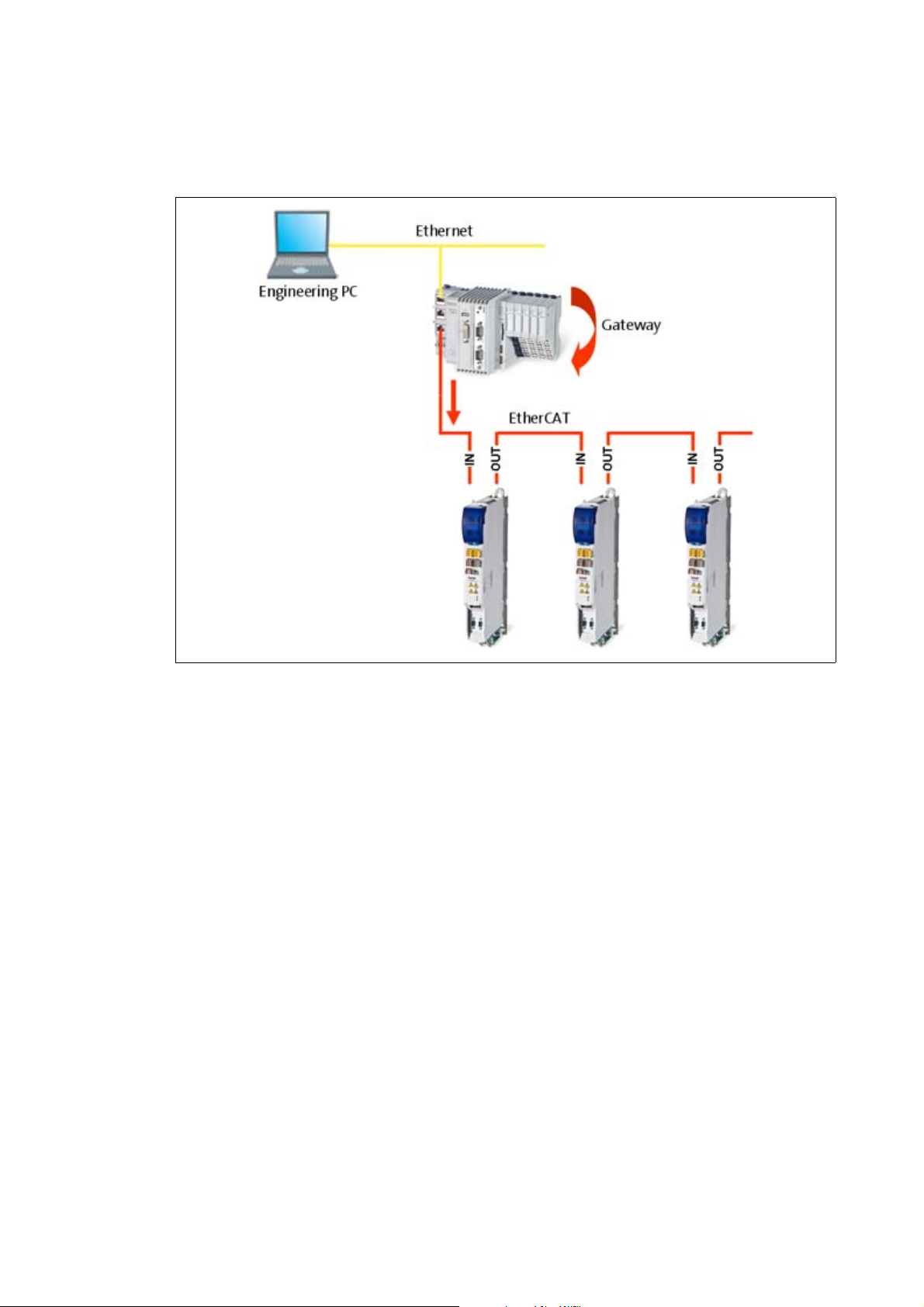
4.4.2.2 EtherCAT bus in operation (gateway function)
You communicate directly via EtherCAT and use the controller as a gateway.
Note!
A PLC program does not need to run to be able to use the gateway function.
[4-6] Example: EtherCAT bus system with 3231 C controller as gateway and i700 servo inverter
Condition:
• The EtherCAT configuration has been created with »PLC Designer« to match the hardware
configuration.
• The EtherCAT configuration has been loaded and activated on the controller with »PLC
Designer«.
• The EtherCAT bus is at least in the "Pre-Operational" state.
Advantage:
• You do not require any additional hardware.
• The process data, parameter data and diagnostic data are transferred via a single bus
connection at the same time.
Lenze · Controller-based Automation · EtherCAT® Communication Manual · DMS 6.4 EN · 04/2014 · TD17 33
Page 34

5Technical data
1
5.1 General data
_ _ _ _ _ _ _ _ _ _ _ _ _ _ _ _ _ _ _ _ _ _ _ _ _ _ _ _ _ _ _ _ _ _ _ _ _ _ _ _ _ _ _ _ _ _ _ _ _ _ _ _ _ _ _ _ _ _ _ _ _ _ _ _
5 Technical data
5.1 General data
Area Values
Higher-level network protocol EtherCAT device protocol
Communication medium / cable
type
Network topology Line
Type within the network Master
Number of nodes Max. 65535 ( in the entire network )
Max. cable length 100 m between two stations
Baud rate 100 Mbps
Supported communication profiles CoE (CANopen over EtherCAT)
Synchronisation Distributed clocks
S/FTP (Screened Foiled Twisted Pair, ISO/IEC 11801 or EN 50173), CAT5e
Standard Ethernet (acc. to IEEE 802.3), 100Base-TX (Fast Ethernet)
FoE (File Access over EtherCAT)
5.2 EtherCAT interface of the Lenze Controller
RJ45 socket Pin Assignment LEDs
E94YCEP018
1 Tx + LED "Link" (green):
2Tx -
3 Rx + LED "Speed" (yellow):
4-
5-
6Rx -
7-
8-
On: connection OK
Blinking: Active data exchange
34
Lenze · Controller-based Automation · EtherCAT® Communication Manual · DMS 6.4 EN · 04/2014 · TD17
Page 35

5Technical data
5.3 Communication times and drive-specific data
_ _ _ _ _ _ _ _ _ _ _ _ _ _ _ _ _ _ _ _ _ _ _ _ _ _ _ _ _ _ _ _ _ _ _ _ _ _ _ _ _ _ _ _ _ _ _ _ _ _ _ _ _ _ _ _ _ _ _ _ _ _ _ _
5.3 Communication times and drive-specific data
Area Values
User data per frame 1344 bytes
Process data words (PCD) Depending on the inverter used
(see documentation of the inverter)
Parameter data (SDO) transfer Max. 128 bytes
Permissible EtherCAT cycle times 1 … 10 ms
Max. number of drives per frame User data of the frame (1344 bytes) divided by the process data length
Cross communication Not possible
Cycle synchronisation with locked
PLL (Jitter)
Instant of transmission for the
EtherCAT frame (for setting, see
Optimising the task utilisation
( 104))
Total signal runtime for a cycle time
of 1 ms
controller drive
Drive
Runtime of the setpoints
Controller
Runtime of the actual values
Drive
drive
controller
resulting from setpoints and actual values of the drives:
• for 32 Tx/Rx bytes: 1344 bytes / 64 bytes = 21 drives
• for 16 Tx/Rx bytes: 1344 bytes / 32 bytes = 42 drives
+/-1 μs
The EtherCAT frame is sent at the
beginning of the bus cycle task.
4 ms 3 ms
2 ms 1 ms
1 ms 1 ms
The EtherCAT frame is sent at the end
of the bus cycle task.
Lenze · Controller-based Automation · EtherCAT® Communication Manual · DMS 6.4 EN · 04/2014 · TD17 35
Page 36

6 Synchronisation with "Distributed clocks" (DC)
_ _ _ _ _ _ _ _ _ _ _ _ _ _ _ _ _ _ _ _ _ _ _ _ _ _ _ _ _ _ _ _ _ _ _ _ _ _ _ _ _ _ _ _ _ _ _ _ _ _ _ _ _ _ _ _ _ _ _ _ _ _ _ _
6 Synchronisation with "Distributed clocks" (DC)
The "Distributed clocks" (DC) functionality enables exact time synchronisation for applications in
which several axes perform a coordinated movement simultaneously. Data are incorporated
synchronously with the PLC program. During DC synchronisation, all slaves are synchronised with a
reference clock, the so-called "DC master".
Note!
• DC synchronisation is absolutely required for Motion applications.
• DC synchronisation can also be used for Logic applications.
• Not all slaves support the DC functionality.
• In order to be able to use the DC functionality, the first slave connected to the
EtherCAT master (Lenze Controller) must have DC master capability. The other slaves
can be connected in a mixed arrangement, either DC capable or non-DC-capable.
• The first EtherCAT slave after the Lenze Controller must
supplies the other EtherCAT nodes (incl. controller) with the exact time.
be the DC master that
[6-1] Example: EtherCAT bus system with 3231 C controller and i700 servo inverter
The settings for the DC synchronisation are made with the »PLC Designer«.
Setting a DC synchronisation
( 87)
36 Lenze · Controller-based Automation · EtherCAT® Communication Manual · DMS 6.4 EN · 04/2014 · TD17
Page 37

6 Synchronisation with "Distributed clocks" (DC)
6.1 Synchronous communication
_ _ _ _ _ _ _ _ _ _ _ _ _ _ _ _ _ _ _ _ _ _ _ _ _ _ _ _ _ _ _ _ _ _ _ _ _ _ _ _ _ _ _ _ _ _ _ _ _ _ _ _ _ _ _ _ _ _ _ _ _ _ _ _
6.1 Synchronous communication
The DC synchronisation provides for a phase-synchronous operation of master and slaves:
Within one bus cycle the setpoints are accepted and the actual values are detected in the fieldbus
at exactly the same time.
If the Lenze Controller (master) is in synch with the distributed clocks, the data (actual values)
acquired by the slave are sent to the master at the end of the bus cycle and data from the master
(setpoint values) are sent to the slaves for processing. .
When the next DC synchronisation event occurs, the data are accepted.
Note!
• The DC synchronisation is only carried out in the "Operational" state.
• After an "Out-of-sync" occurrence, the EtherCAT master synchronises the slaves.
Successful synchronisation is indicated by means of the "In-Sync" message (see
Diagnostic tabs of the EtherCAT master
( 164)).
Lenze · Controller-based Automation · EtherCAT® Communication Manual · DMS 6.4 EN · 04/2014 · TD17 37
Page 38

6 Synchronisation with "Distributed clocks" (DC)
6.2 Test of DC synchronicity
_ _ _ _ _ _ _ _ _ _ _ _ _ _ _ _ _ _ _ _ _ _ _ _ _ _ _ _ _ _ _ _ _ _ _ _ _ _ _ _ _ _ _ _ _ _ _ _ _ _ _ _ _ _ _ _ _ _ _ _ _ _ _ _
6.2 Test of DC synchronicity
DC synchronicity is only available in the "Operational" state.
Test of DC synchronicity in »PLC Designer«
•EtherCAT master: Diagnostic Master tab
"DC In-Sync" is set (TRUE) if the DC master and all DC slaves have been synchronised.
Diagnostic tabs of the EtherCAT master
• Function block L_ETC_GetMasterDiagnostic (FB)
L_ETC_GetMasterDiagnostic ( 166)
"DC In-Sync" is set (TRUE) at the oDiagnostic.xDC_InSync output if the DC master AND all DC
slaves are synchronised.
( 164)
( 144) / Visualisation of the function block
• Function block L_IODrvEtherCAT (FB)
"DC In-Sync" is set (TRUE) at the xDistributedClockInSync output if all DC slaves are synchronised.
Test of DC synchronicity in »WebConfig«:
In the code C281/5
Diagnostic codes in the »WebConfig«
, "DC In-Sync" is set (TRUE) if all DC slaves have been synchronised.
( 140)
( 169)
38
Lenze · Controller-based Automation · EtherCAT® Communication Manual · DMS 6.4 EN · 04/2014 · TD17
Page 39

7 Commissioning of the system
7.1 Sample projects (Application Samples)
_ _ _ _ _ _ _ _ _ _ _ _ _ _ _ _ _ _ _ _ _ _ _ _ _ _ _ _ _ _ _ _ _ _ _ _ _ _ _ _ _ _ _ _ _ _ _ _ _ _ _ _ _ _ _ _ _ _ _ _ _ _ _ _
7 Commissioning of the system
This chapter provides information on how to commission the Lenze automation system with
EtherCAT.
Depending on the field devices used, the following Lenze Engineering tools
• »EASY Starter«
• »Engineer«
•»PLC Designer«
7.1 Sample projects (Application Samples)
There already exist sample projects (device application + PLC program) for commissioning of Lenze
inverters.
The Lenze sample projects can be found in the MS Windows start menu under:
Start All programs Lenze AppSamples ...
( 29) are required:
The Lenze sample projects can also be opened in the »PLC Designer« via the menu command File
New project..., or using <Ctrl>+<N>.
Detailed information on the sample projects can be found in the following
documentation:
• SW_ApplicationSample_i700_(PLC Designer V3)_Vx-y_DE/EN.pdf
• SW_ApplicationSamples_(Controller-based)_Vx-y_DE/EN.pdf
Lenze · Controller-based Automation · EtherCAT® Communication Manual · DMS 6.4 EN · 04/2014 · TD17 39
Page 40

7 Commissioning of the system
7.2 Overview of the commissioning steps
_ _ _ _ _ _ _ _ _ _ _ _ _ _ _ _ _ _ _ _ _ _ _ _ _ _ _ _ _ _ _ _ _ _ _ _ _ _ _ _ _ _ _ _ _ _ _ _ _ _ _ _ _ _ _ _ _ _ _ _ _ _ _ _
7.2 Overview of the commissioning steps
In the following illustration, the individual commissioning steps and their processing order are
summarised. Detailed information on the individual processing steps can be found in the chapter
Detailed description of the commissioning steps
( 42).
40
Lenze · Controller-based Automation · EtherCAT® Communication Manual · DMS 6.4 EN · 04/2014 · TD17
Page 41

7 Commissioning of the system
7.2 Overview of the commissioning steps
_ _ _ _ _ _ _ _ _ _ _ _ _ _ _ _ _ _ _ _ _ _ _ _ _ _ _ _ _ _ _ _ _ _ _ _ _ _ _ _ _ _ _ _ _ _ _ _ _ _ _ _ _ _ _ _ _ _ _ _ _ _ _ _
The main commissioning steps are listed in the following table:
Step Activity Lenze software to be
1. Installing field devices
2. Create a project folder
3. Commissioning the i700 servo inverter
Commissioning other Lenze field devices
4. Creating a PLC program with a target system (Logic/Motion)
5. Configuring the communication parameters
6. Determining the physical EtherCAT configuration (fieldbus scan)
If necessary Importing missing devices / device description files
7. Creating a control configuration (adding field devices)
8. Creating a task
9. Setting a DC synchronisation
10. Setting SoftMotion parameters
Only required for drives with Motion functionality.
11. Processing EtherCAT I/O mapping
Only required for drives that solely have the master functionality (logic bus).
12. Compiling the PLC program code
13. Logging in on the controller with the »PLC Designer«
With the log-in, the fieldbus configuration and the PLC program are loaded into
the Controller.
14. Starting the PLC program
( 43)
( 43)
( 44) »PLC Designer«
( 70) »Engineer« /
( 71) »PLC Designer«
( 73)
( 75)
( 78)
( 79)
( 82)
( 87)
( 92)
( 95)
( 103)
( 103)
( 103)
used
»EASY Starter«
Lenze · Controller-based Automation · EtherCAT® Communication Manual · DMS 6.4 EN · 04/2014 · TD17 41
Page 42

7 Commissioning of the system
7.3 Detailed description of the commissioning steps
_ _ _ _ _ _ _ _ _ _ _ _ _ _ _ _ _ _ _ _ _ _ _ _ _ _ _ _ _ _ _ _ _ _ _ _ _ _ _ _ _ _ _ _ _ _ _ _ _ _ _ _ _ _ _ _ _ _ _ _ _ _ _ _
7.3 Detailed description of the commissioning steps
In the following sections, the individual commissioning steps are described.
Follow the instructions of these sections step by step in order to commission your system.
For more details on how to use the Lenze engineering tools, please refer to the
corresponding software manuals and the online help systems.
7.3.1 Planning the bus topology
Before you set up an EtherCAT network, draw up a plan of the network.
How to plan the bus topology for your configuration
1. Create an overview screen of the planned EtherCAT network with all the field devices to be
integrated into the network.
2. Start with the Lenze Controller (master).
3. Add the other field devices (slaves) below.
The following cases are distinguished:
• Operation without
DC synchronisation is mostly not required if exclusively Logic field devices are to be
operated on the network. The sequence of the field devices on the fieldbus can be freely
selected.
• Operation with
DC synchronisation is required if Motion and Logic field devices are to be operated on the
network. The first node connected to the Lenze Controller must be capable of being a DC
master. The sequence of the other Logic and Motion field device interface connections at
the fieldbus can be freely selected.
synchronisation via distributed clocks:
synchronisation via distributed clocks:
42
Lenze · Controller-based Automation · EtherCAT® Communication Manual · DMS 6.4 EN · 04/2014 · TD17
Page 43

7 Commissioning of the system
7.3 Detailed description of the commissioning steps
_ _ _ _ _ _ _ _ _ _ _ _ _ _ _ _ _ _ _ _ _ _ _ _ _ _ _ _ _ _ _ _ _ _ _ _ _ _ _ _ _ _ _ _ _ _ _ _ _ _ _ _ _ _ _ _ _ _ _ _ _ _ _ _
7.3.2 Installing field devices
For the installation of a field device, follow the mounting instructions for the respective device.
Note!
• In the case of all field devices, the EtherCAT interfaces must be wired in accordance
with the preceding topology planning. Make sure that the inputs (IN) and outputs
(OUT) are not mixed up with each other; otherwise, the topology changes.
Communication
• The physical sequence of the field devices in the EtherCAT network must match the
EtherCAT configuration created in »PLC Designer«.
• The master automatically assigns the node addresses to the slaves. Therefore, a
manual address assignment is not required.
7.3.3 Create a project folder
( 19)
Create a project folder on the Engineering PC.
Use this project folder to store the data generated in the following different project configuration
steps:
• Project data created in the »Engineer« or »EASY Starter«
• Project data created in »PLC Designer«
Tip!
Create a separate project folder for every EtherCAT configuration and store the project files.
Lenze · Controller-based Automation · EtherCAT® Communication Manual · DMS 6.4 EN · 04/2014 · TD17 43
Page 44

7 Commissioning of the system
7.3 Detailed description of the commissioning steps
_ _ _ _ _ _ _ _ _ _ _ _ _ _ _ _ _ _ _ _ _ _ _ _ _ _ _ _ _ _ _ _ _ _ _ _ _ _ _ _ _ _ _ _ _ _ _ _ _ _ _ _ _ _ _ _ _ _ _ _ _ _ _ _
7.3.4 Commissioning the i700 servo inverter
This chapter tells you how to commission the Servo-Inverter i700 in the Lenze automation system
with the help of »PLC Designer«.
For speed commissioning, the Servo-Inverter i700 provides diverse functions for automatic
calculation and setting of parameters.
Danger!
Severe personal injury and damage to the machine/installation
Activate the controller inhibit before you set the parameters for the Servo-Inverter i700
as uncontrolled movements can lead to severe personal injury and damage to the
machine/installation.
Note!
You can also set the parameters for the Servo-Inverter i700 online. To do this, you must
first configure EtherCAT communication.
Setting parameters online is possible from the EtherCAT state "Pre-Operational"
onwards.
Reference manual/online help for the i700 servo inverter
Here, you can find detailed information on all parameters/Objects (object dictionary),
functions and error messages of the i700 servo inverter.
Tip!
There already exist sample projects (device application + PLC program) for commissioning
of the i700 servo inverter.
Sample projects (Application Samples)
( 39)
44
Lenze · Controller-based Automation · EtherCAT® Communication Manual · DMS 6.4 EN · 04/2014 · TD17
Page 45

7 Commissioning of the system
7.3 Detailed description of the commissioning steps
_ _ _ _ _ _ _ _ _ _ _ _ _ _ _ _ _ _ _ _ _ _ _ _ _ _ _ _ _ _ _ _ _ _ _ _ _ _ _ _ _ _ _ _ _ _ _ _ _ _ _ _ _ _ _ _ _ _ _ _ _ _ _ _
7.3.4.1 i700 parameter management in the Controller-based Automation system
Parameter download
The Servo-Inverter i700 itself does not
inverter settings deviating from the Lenze standard setting are maintained centrally in the Lenze
Controller and stored there permanently (persistently). During the initialisation at run-up, only
these deviations are transferred to the servo inverter by the controller. Like this it is ensured that the
servo inverter works with the parameter settings provided for it.
Firmware download (optional)
The firmware of the Servo-Inverter i700 can– if so desired– be stored together with the »PLC
Designer« project. When the system is being powered up, the Lenze Controller then checks whether
the firmware version in the servo inverter matches the firmware version stored in the project for
this device. If this is not the case, the controller loads the firmware version stored in the project into
the servo inverter. In the event of a "Device replacement" service, it can thus be ensured that the
replacement device works with the same firmware version stored in the project for the original
device.
store parameter settings safe against mains failure. All servo
Lenze · Controller-based Automation · EtherCAT® Communication Manual · DMS 6.4 EN · 04/2014 · TD17 45
Page 46

7 Commissioning of the system
7.3 Detailed description of the commissioning steps
_ _ _ _ _ _ _ _ _ _ _ _ _ _ _ _ _ _ _ _ _ _ _ _ _ _ _ _ _ _ _ _ _ _ _ _ _ _ _ _ _ _ _ _ _ _ _ _ _ _ _ _ _ _ _ _ _ _ _ _ _ _ _ _
[7-1] Parameter set transfer from »PLC Designer« to the Servo-Inverter i700 via the 3231 C controller
The parameters of the Servo-Inverter i700 are managed within the »PLC Designer« project. With the
help of the storage function of »PLC Designer«, the »PLC Designer« project, including the i700
parameters, are stored on the Engineering PC.
During login to the Lenze Controller,»PLC Designer« transfers the i700 parameters to the controller.
The latter, in turn, transfers the parameter sets to the lower-level Servo-Inverter i700.
Whenever the system is booted, the parameter sets are written into the Servo-Inverter i700 again
by the Lenze Controller.
46
Lenze · Controller-based Automation · EtherCAT® Communication Manual · DMS 6.4 EN · 04/2014 · TD17
Page 47

7 Commissioning of the system
7.3 Detailed description of the commissioning steps
_ _ _ _ _ _ _ _ _ _ _ _ _ _ _ _ _ _ _ _ _ _ _ _ _ _ _ _ _ _ _ _ _ _ _ _ _ _ _ _ _ _ _ _ _ _ _ _ _ _ _ _ _ _ _ _ _ _ _ _ _ _ _ _
There are three cases of application for the management and alteration of parameters:
A. Changing parameters of an Servo-Inverter i700 online:
If a parameter is changed online, »PLC Designer« writes the parameter directly into the
corresponding servo inverter and, at the same time, changes the parameter in the»PLC
Designer« project.
N.B.:
The parameter change is not
the controller, the parameter change in the servo inverter is lost.
In order to avoid this, log out with the »PLC Designer« and then log in again. (Menu commands:
Online Logout / Online Login)
Like this, the complete parameter set is written to the controller and is transferred to the servo
inverter.
After the transfer by log-in, the parameter set is only available in the servo inverter and in the
controller until the next switch-off of the system (it is not saved with mains failure protection).
B. Changing parameters of a Servo-Inverter i700 offline:
If a parameter is changed offline, the »PLC Designer« changes the value directly in the »PLC
Designer« project. When logging in on the Lenze Controller, the complete parameter set is
written to the controller, which, in turn, then transfers the parameter set to the servo inverter.
After the transfer by log-in, the parameter set is only available in the servo inverter and in the
controller until the next switch-off of the system (it is not saved with mains failure protection).
recorded in the Lenze Controller. In the event of a "cold reset" of
Lenze · Controller-based Automation · EtherCAT® Communication Manual · DMS 6.4 EN · 04/2014 · TD17 47
Page 48

7 Commissioning of the system
7.3 Detailed description of the commissioning steps
_ _ _ _ _ _ _ _ _ _ _ _ _ _ _ _ _ _ _ _ _ _ _ _ _ _ _ _ _ _ _ _ _ _ _ _ _ _ _ _ _ _ _ _ _ _ _ _ _ _ _ _ _ _ _ _ _ _ _ _ _ _ _ _
C. Store the parameters of the Servo-Inverter i700 in a non-volatile memory so that they are
retained in the device when the power is switched off:
In the boot project of the Lenze Controller, there is a separate parameter set for the lower-level
Servo-Inverters i700. The latter is then only updated when the "boot project" function is
executed via the »PLC Designer«. The current parameterisation is then saved and is available
after mains switching. During boot-up after mains connection, the saved parameter set is
automatically written from the controller into the servo inverter.
[7-2] Parameter set transfer from the 3231 C controller to the Servo-Inverter i700 during a boot-up
48
Lenze · Controller-based Automation · EtherCAT® Communication Manual · DMS 6.4 EN · 04/2014 · TD17
Page 49

7 Commissioning of the system
7.3 Detailed description of the commissioning steps
_ _ _ _ _ _ _ _ _ _ _ _ _ _ _ _ _ _ _ _ _ _ _ _ _ _ _ _ _ _ _ _ _ _ _ _ _ _ _ _ _ _ _ _ _ _ _ _ _ _ _ _ _ _ _ _ _ _ _ _ _ _ _ _
7.3.4.2 i700 parameter management in »EASY Starter«
For parameter management in »EASY Starter«, you must insert the Lenze Controller and the ServoInverter i700 into the device list with the help of the button.
[7-3] Parameter set transfer with »EASY Starter«
With »EASY Starter«, there are two application cases for parameter management:
A. Storing the current Servo-Inverter i700 parameter setting in the Lenze Controller with mains
failure protection:
• Select the Lenze Controller from the device list.
• With the button or the <F6> function key, store the parameter set in the controller so that
it is saved there even in the event of a power failure. (To this end, the controller uploads all
the parameter sets of the lower-level i700 servo inverter.)
• After the system has been switched off and then switched on again. the controller transfers
the parameter sets to the i700 inverter again.
Lenze · Controller-based Automation · EtherCAT® Communication Manual · DMS 6.4 EN · 04/2014 · TD17 49
Page 50

7 Commissioning of the system
7.3 Detailed description of the commissioning steps
_ _ _ _ _ _ _ _ _ _ _ _ _ _ _ _ _ _ _ _ _ _ _ _ _ _ _ _ _ _ _ _ _ _ _ _ _ _ _ _ _ _ _ _ _ _ _ _ _ _ _ _ _ _ _ _ _ _ _ _ _ _ _ _
B. Upload the parameters currently set in a Servo-Inverter i700 to the Engineering PC and store
them there:
• Select a Servo-Inverter i700 in the device list
• With the button or the <F7> function key, upload the parameter set of the servo inverter.
(The parameter set of the servo inverter is transferred directly to »EASY Starter« without the
parameter set being stored on the controller.)
•With the Save button, store the parameter as a GDC file on the Engineering PC.
50
Lenze · Controller-based Automation · EtherCAT® Communication Manual · DMS 6.4 EN · 04/2014 · TD17
Page 51

7 Commissioning of the system
7.3 Detailed description of the commissioning steps
_ _ _ _ _ _ _ _ _ _ _ _ _ _ _ _ _ _ _ _ _ _ _ _ _ _ _ _ _ _ _ _ _ _ _ _ _ _ _ _ _ _ _ _ _ _ _ _ _ _ _ _ _ _ _ _ _ _ _ _ _ _ _ _
7.3.4.3 Exchanging i700 parameter sets between »PLC Designer« and »EASY Starter«
[7-4] Parameter set transfer between »PLC Designer« and »EASY Starter«
The GDC files that have been stored on the Engineering PC with the help of »EASY Starter« can be
imported in »PLC Designer«.
It is also possible to export GDC files with »PLC Designer«; they can then be imported in »EASY
Starter«.
In the framework of this import/export functionality, the parameter settings of a single axis can be
imported into a double axis, for example.
How to import parameters in »PLC Designer«
1. Log out of the Lenze Controller with the menu command Online Logout or <Ctrl>+<F8>.
2. Select the corresponding Servo-Inverter i700 in the project tree.
3. Select and import the corresponding GDC file with the menu command Project Device
parameters Import device parameters.
4. Use the menu command Online Login or <Alt>+<F8> to log in on the Lenze Controller.
• For this, the PLC program must be error-free.
• The complete parameter set is written into the controller. The latter than transfers the
parameter set to the i700 servo inverter.
Parameters are exported in »PLC Designer« in a similar way with the help of the menu command
Project Device parameters Export device parameters.
Lenze · Controller-based Automation · EtherCAT® Communication Manual · DMS 6.4 EN · 04/2014 · TD17 51
Page 52

7 Commissioning of the system
7.3 Detailed description of the commissioning steps
_ _ _ _ _ _ _ _ _ _ _ _ _ _ _ _ _ _ _ _ _ _ _ _ _ _ _ _ _ _ _ _ _ _ _ _ _ _ _ _ _ _ _ _ _ _ _ _ _ _ _ _ _ _ _ _ _ _ _ _ _ _ _ _
7.3.4.4 Overview of the commissioning steps
The main commissioning steps are listed in the following table:
Step Activity
1. Create a project folder
2. Creating a PLC program with a target system (Logic/Motion)
3. Configuring the communication parameters
4. Determining the physical EtherCAT configuration (fieldbus scan)
or
Creating a control configuration (adding field devices)
5. Creating a task
6. Setting a DC synchronisation
7. Checking the wiring
8. Entering motor and controller settings
9. Setting the feedback system for servo control
10. Integrating the L_SMC_AxisBasicControl function block
11. Setting SoftMotion parameters
Only required for drives with Motion functionality.
12. Processing EtherCAT I/O mapping
Only required for drives that solely have the master functionality (logic bus).
13. Compiling the PLC program code
14. Logging in on the controller with the »PLC Designer«
With the log-in, the fieldbus configuration and the PLC program are loaded into the Controller.
15. Starting the PLC program
16. Executing manual control
17. Optimising control
( 43)
( 71)
( 73)
( 75)
( 79)
( 82)
( 87)
( 54)
( 54)
( 57)
( 59)
( 92)
( 95)
( 103)
( 103)
( 103)
( 65)
( 67)
52
Lenze · Controller-based Automation · EtherCAT® Communication Manual · DMS 6.4 EN · 04/2014 · TD17
Page 53

7 Commissioning of the system
7.3 Detailed description of the commissioning steps
_ _ _ _ _ _ _ _ _ _ _ _ _ _ _ _ _ _ _ _ _ _ _ _ _ _ _ _ _ _ _ _ _ _ _ _ _ _ _ _ _ _ _ _ _ _ _ _ _ _ _ _ _ _ _ _ _ _ _ _ _ _ _ _
7.3.4.5 Checking the wiring
Before you start to set the parameters of the drive control system, check the wiring of the motor
(power and encoder connections) for faults.
For this purpose, you can activate the following test modes with the controller command Operating
mode (0x2825 / 0x3025):
• Test mode: Voltage/frequency
• Test mode: Current/frequency
• Test mode: Current pulse
• Executing manual control
( 65)
[7-5] Example: operating modes for i700 servo inverter, double axis
Lenze · Controller-based Automation · EtherCAT® Communication Manual · DMS 6.4 EN · 04/2014 · TD17 53
Page 54

7 Commissioning of the system
7.3 Detailed description of the commissioning steps
_ _ _ _ _ _ _ _ _ _ _ _ _ _ _ _ _ _ _ _ _ _ _ _ _ _ _ _ _ _ _ _ _ _ _ _ _ _ _ _ _ _ _ _ _ _ _ _ _ _ _ _ _ _ _ _ _ _ _ _ _ _ _ _
7.3.4.6 Entering motor and controller settings
You can enter the motor and controller settings on the Motor commissioning tab of the i700 servo
inverter.
[7-6] Example: i700 servo inverter, double axis
How to enter the motor and controller settings
1. Go to the Motor selection section and specify the data of the motor to be operated in
conjunction with the i700 servo inverter.
A. Select the Lenze motor from the motor catalogue by clicking the Select motor... button.
• The corresponding motor data will then be incorporated in the »PLC Designer« project.
• The controller parameters are calculated automatically.
or
B. Enter the motor data manually or specify them by means of an identification run (e.g. in
the case of motors from other manufacturers).
The controller parameters are calculated automatically.
54
Lenze · Controller-based Automation · EtherCAT® Communication Manual · DMS 6.4 EN · 04/2014 · TD17
Page 55

7 Commissioning of the system
7.3 Detailed description of the commissioning steps
_ _ _ _ _ _ _ _ _ _ _ _ _ _ _ _ _ _ _ _ _ _ _ _ _ _ _ _ _ _ _ _ _ _ _ _ _ _ _ _ _ _ _ _ _ _ _ _ _ _ _ _ _ _ _ _ _ _ _ _ _ _ _ _
2. Select Control method (0x2C00 / 0x3400):
• Servo control for synchronous motor (SM)
• Servo control for asynchronous motor (ASM)
• VFC: V/f characteristic control
3. If you do not
inertia (0x2910/1 / 0x3110/1) to a non-zero value.
The controller parameters are calculated automatically.
4. You can select the parameters for the monitoring functions in the Monitoring settings
section.
obtain the motor data from the catalog, you have to set the moment of
Lenze · Controller-based Automation · EtherCAT® Communication Manual · DMS 6.4 EN · 04/2014 · TD17 55
Page 56

7 Commissioning of the system
7.3 Detailed description of the commissioning steps
_ _ _ _ _ _ _ _ _ _ _ _ _ _ _ _ _ _ _ _ _ _ _ _ _ _ _ _ _ _ _ _ _ _ _ _ _ _ _ _ _ _ _ _ _ _ _ _ _ _ _ _ _ _ _ _ _ _ _ _ _ _ _ _
5. Retain or alter the automatically calculated controller parameters under Control.
56
Lenze · Controller-based Automation · EtherCAT® Communication Manual · DMS 6.4 EN · 04/2014 · TD17
Page 57

7 Commissioning of the system
7.3 Detailed description of the commissioning steps
_ _ _ _ _ _ _ _ _ _ _ _ _ _ _ _ _ _ _ _ _ _ _ _ _ _ _ _ _ _ _ _ _ _ _ _ _ _ _ _ _ _ _ _ _ _ _ _ _ _ _ _ _ _ _ _ _ _ _ _ _ _ _ _
7.3.4.7 Setting the feedback system for servo control
Danger!
Using the encoder/resolver as a motor encoder
In the Lenze setting, the resolver/encoder cable is monitored for open circuit.
In the event of a fault, safe operation of the motor is no longer guaranteed!
• For safety reasons, always select "Fault" (Lenze setting) as a response for the (opencircuit) monitoring of the encoder/resolver.
• To avoid interference injections when an encoder is used, only use shielded motor and
encoder cables.
Determining the pole position of the synchronous motor
Pole position identification (angle between the motor phase U and the field axis of the rotor) is
necessary ...
• for servo control with a synchronous motor of another manufacturer;
• for servo control with a synchronous motor and use of incremental encoders (TTL or sin/cos
encoder and resolver);
• after changes to the feedback system (e.g. replacement of the encoder).
For Lenze motors with an absolute encoder or resolver, the pole position has already been set
correctly.
Danger!
• During pole position identification, it must be ensured that the motor is not braked or
blocked. Pole position identification is therefore not permissible in the case of
hanging loads.
• The rotor will align itself during pole position identification. The motor shaft will
make a maximum of one electrical rotation, as a result of which the connected
machine will move accordingly.
• For firmly braked motors, the function "Pole position identification PPI (without
movement)" must be used.
Stop!
Before carrying out pole position identification, check that the parameters for maximum
current monitoring have been set correctly so that the motor is not permanently
damaged in the event of a fault.
Lenze · Controller-based Automation · EtherCAT® Communication Manual · DMS 6.4 EN · 04/2014 · TD17 57
Page 58

7 Commissioning of the system
7.3 Detailed description of the commissioning steps
_ _ _ _ _ _ _ _ _ _ _ _ _ _ _ _ _ _ _ _ _ _ _ _ _ _ _ _ _ _ _ _ _ _ _ _ _ _ _ _ _ _ _ _ _ _ _ _ _ _ _ _ _ _ _ _ _ _ _ _ _ _ _ _
Either of the functions Pole position identification for 360°, Pole position identification
with min. movement and Pole position identification without movement can be selected in
order to determine the pole position for the currently activated motor encoder:
The functions should deliver approximately the same result. Due to e.g. friction, bearing forces, and
a trapezoidal field curve, however, the results can differ from each other. Here the method with one
full revolution (360°) will provide the most precise results and the method without any movement
will provide the most inaccurate results. The precision of the results can be increased by increasing
the percentage of the current amplitude.
After successful completion of pole position identification ...
... the controller inhibit is set automatically and the Resolver pole position (0x2C03/2 / 0x3403/
2) or the Encoder pole position (0x2C03/4 / 0x3403/4) determined for the activated feedback
system is set.
• For permanent storage, the changed settings must be uploaded from the Servo-Inverter i700 to
the Lenze Controller.
The »EASY Starter« can be used to upload the parameters of the servo inverter and to save them
as a file. This file can then be imported to the »PLC Designer«.
• The controller inhibit automatically set by the procedure can be deactivated via the CiA402
control word (0x6040 / 0x6840).
If an error occurs
If an error occurs during pole position identification or if pulse inhibit becomes active (e.g. due to
short-term undervoltage), the procedure is ended with controller inhibit without the settings being
changed.
If the motor was braked or blocked during pole position identification, this is detected at the end of
a measurement and no changes are made.
58
If pole position identification is aborted, the reaction set in the object, namely 0x2C60/0x3460
(monitoring of pole position identification: reaction) is triggered (Lenze setting: Fault).
Lenze · Controller-based Automation · EtherCAT® Communication Manual · DMS 6.4 EN · 04/2014 · TD17
Page 59

7 Commissioning of the system
7.3 Detailed description of the commissioning steps
_ _ _ _ _ _ _ _ _ _ _ _ _ _ _ _ _ _ _ _ _ _ _ _ _ _ _ _ _ _ _ _ _ _ _ _ _ _ _ _ _ _ _ _ _ _ _ _ _ _ _ _ _ _ _ _ _ _ _ _ _ _ _ _
7.3.4.8 Integrating the L_SMC_AxisBasicControl function block
For operating the Servo-Inverter i700, the L_SMC_AxisBasicControl function block has to be
integrated into the »PLC Designer« project.
The function block ...
• contains various variables for drive control (e.g. for quick stop function (QSP), following error
monitoring, etc.);
•is part of the L_SM3_DriveUtil.lib function library.
»PLC Designer« online help
Here you can find detailed information on the function block.
Lenze · Controller-based Automation · EtherCAT® Communication Manual · DMS 6.4 EN · 04/2014 · TD17 59
Page 60

7 Commissioning of the system
7.3 Detailed description of the commissioning steps
_ _ _ _ _ _ _ _ _ _ _ _ _ _ _ _ _ _ _ _ _ _ _ _ _ _ _ _ _ _ _ _ _ _ _ _ _ _ _ _ _ _ _ _ _ _ _ _ _ _ _ _ _ _ _ _ _ _ _ _ _ _ _ _
How to integrate the L_SMC_AxisBasicControl function block into the »PLC Designer«
project:
1. Open the PLC program code (PLC_PRG).
2. Open Input assistance in the lower input area with a right mouse click via the context
menu.
3. Open the category Function blocks.
4. In the element L_SM3, select POUs and then the L_SMC_AxisBasicControl function
block.
60
5. In the "Declare variables" dialog box, enter a variable name (in the example above:
"MC_Test_i700").
Lenze · Controller-based Automation · EtherCAT® Communication Manual · DMS 6.4 EN · 04/2014 · TD17
Page 61

7 Commissioning of the system
7.3 Detailed description of the commissioning steps
_ _ _ _ _ _ _ _ _ _ _ _ _ _ _ _ _ _ _ _ _ _ _ _ _ _ _ _ _ _ _ _ _ _ _ _ _ _ _ _ _ _ _ _ _ _ _ _ _ _ _ _ _ _ _ _ _ _ _ _ _ _ _ _
6. Close the variable declaration by clicking the OK button.
The L_SMC_AxisBasicControl function block, together with its data structure, is
integrated into the PLC program code.
7. Open the L_SMC_AxisBasicControl function block and set the reference to the axis
data structure (in the example "Axis:= SM_Drive_ETC_i700").
Lenze · Controller-based Automation · EtherCAT® Communication Manual · DMS 6.4 EN · 04/2014 · TD17 61
Page 62

7 Commissioning of the system
7.3 Detailed description of the commissioning steps
_ _ _ _ _ _ _ _ _ _ _ _ _ _ _ _ _ _ _ _ _ _ _ _ _ _ _ _ _ _ _ _ _ _ _ _ _ _ _ _ _ _ _ _ _ _ _ _ _ _ _ _ _ _ _ _ _ _ _ _ _ _ _ _
8. Open the context menu for Application, select the command Add object Visualisation...
and then insert the visualisation of the function block.
Enter an appropriate name (e.g. "VISU_L_SMC_AxisBasicControl").
62
Lenze · Controller-based Automation · EtherCAT® Communication Manual · DMS 6.4 EN · 04/2014 · TD17
Page 63

7 Commissioning of the system
7.3 Detailed description of the commissioning steps
_ _ _ _ _ _ _ _ _ _ _ _ _ _ _ _ _ _ _ _ _ _ _ _ _ _ _ _ _ _ _ _ _ _ _ _ _ _ _ _ _ _ _ _ _ _ _ _ _ _ _ _ _ _ _ _ _ _ _ _ _ _ _ _
9. Insert a frame in the visualisation with the help of the frame tool.
10. Add the frame visualisation of the function block L_SMC_AxisBasicControl and close the
dialog box by clicking the OK button.
Lenze · Controller-based Automation · EtherCAT® Communication Manual · DMS 6.4 EN · 04/2014 · TD17 63
Page 64

7 Commissioning of the system
7.3 Detailed description of the commissioning steps
_ _ _ _ _ _ _ _ _ _ _ _ _ _ _ _ _ _ _ _ _ _ _ _ _ _ _ _ _ _ _ _ _ _ _ _ _ _ _ _ _ _ _ _ _ _ _ _ _ _ _ _ _ _ _ _ _ _ _ _ _ _ _ _
11. Under "Properties", select the reference of the function block with which the visualisation
is to be connected (in the example "MC_Test_i700").
12. Confirm your selection by clicking the OK button.
13. Translate the PLC program code.
Menu command Build Build or <F11> function key
14. Store the »PLC Designer« project in the project folder.
Menu command File Save project / Save project as ...
64
Lenze · Controller-based Automation · EtherCAT® Communication Manual · DMS 6.4 EN · 04/2014 · TD17
Page 65

7 Commissioning of the system
7.3 Detailed description of the commissioning steps
_ _ _ _ _ _ _ _ _ _ _ _ _ _ _ _ _ _ _ _ _ _ _ _ _ _ _ _ _ _ _ _ _ _ _ _ _ _ _ _ _ _ _ _ _ _ _ _ _ _ _ _ _ _ _ _ _ _ _ _ _ _ _ _
7.3.4.9 Executing manual control
The purpose of manual control is to check the wiring (test mode) and to carry out a traversing
movement.
Note!
For problem-free manual control, the machine parameters – at least the gearbox factor
and feed constant – must be set correctly.
Preconditions for manual control
• No faults are active.
• The mains voltage has been switched on.
• The STO function (Safe Torque Off) is not active.
• The inverter drive has been inhibited by means of the software.
How to activate manual control
1. Use the menu command Online Login, or log in on the Lenze Controller with <Alt>+<F8>.
• For this, the PLC program must be error-free.
• By means of the log-in, the PLC program is loaded into the controller. In doing so, any
existing program is overwritten.
2. If the inverter has been enabled, inhibit it via »PLC Designer«.
3. Open the context menu of the Servo-Inverter i700 to be traversed and execute the
command Manual control.
Lenze · Controller-based Automation · EtherCAT® Communication Manual · DMS 6.4 EN · 04/2014 · TD17 65
Page 66

7 Commissioning of the system
7.3 Detailed description of the commissioning steps
_ _ _ _ _ _ _ _ _ _ _ _ _ _ _ _ _ _ _ _ _ _ _ _ _ _ _ _ _ _ _ _ _ _ _ _ _ _ _ _ _ _ _ _ _ _ _ _ _ _ _ _ _ _ _ _ _ _ _ _ _ _ _ _
The dialog box for manual control appears:
4. Enable the inverter drive via the »PLC Designer«.
5. Enter the traversing speed (speed) in the dialog box.
Value as a percentage of maximum motor speed (0x6080):
• Positive % value: clockwise movement
• Negative % value: counterclockwise movement
6. Click the button to start manual mode.
Manual mode can be stopped by clicking the button.
66
Lenze · Controller-based Automation · EtherCAT® Communication Manual · DMS 6.4 EN · 04/2014 · TD17
Page 67

7 Commissioning of the system
7.3 Detailed description of the commissioning steps
_ _ _ _ _ _ _ _ _ _ _ _ _ _ _ _ _ _ _ _ _ _ _ _ _ _ _ _ _ _ _ _ _ _ _ _ _ _ _ _ _ _ _ _ _ _ _ _ _ _ _ _ _ _ _ _ _ _ _ _ _ _ _ _
7.3.4.10 Optimising control
The final controller settings are carried out online during commissioning with load on the real
machine.
How to optimise the control system
1. Use the menu command Online Login, or log in on the Lenze Controller with <Alt>+<F8>.
• For this, the PLC program must be error-free.
• By means of the log-in, the PLC program is loaded into the controller. In doing so, any
existing program is overwritten.
2. Press the <F5> function key to start the PLC program.
3. Open the tab Signal flow Chart A and select the display mode (operating mode).
The corresponding signal flow diagram is shown with the current parameter values.
Lenze · Controller-based Automation · EtherCAT® Communication Manual · DMS 6.4 EN · 04/2014 · TD17 67
Page 68

7 Commissioning of the system
7.3 Detailed description of the commissioning steps
_ _ _ _ _ _ _ _ _ _ _ _ _ _ _ _ _ _ _ _ _ _ _ _ _ _ _ _ _ _ _ _ _ _ _ _ _ _ _ _ _ _ _ _ _ _ _ _ _ _ _ _ _ _ _ _ _ _ _ _ _ _ _ _
4. Adapt parameter values in order to optimise the control system.
• In the signal flow diagrams, you can adapt some parameter values directly in the
corresponding input fields.
• In addition, you can adapt parameter values for particular functions by means of
function buttons, depending on the operating mode being used (see table below).
68
Lenze · Controller-based Automation · EtherCAT® Communication Manual · DMS 6.4 EN · 04/2014 · TD17
Page 69

7 Commissioning of the system
7.3 Detailed description of the commissioning steps
_ _ _ _ _ _ _ _ _ _ _ _ _ _ _ _ _ _ _ _ _ _ _ _ _ _ _ _ _ _ _ _ _ _ _ _ _ _ _ _ _ _ _ _ _ _ _ _ _ _ _ _ _ _ _ _ _ _ _ _ _ _ _ _
Functions and buttons in the signal flow diagrams
Function Button Operating mode
Servo control SM/ASM V/f control
Velocity mode
Cyclical synchr.
position mode
Cyclical synchr.
velocity mode
Cyclical synchr.
torque mode
Velocity mode
Cyclical synchr.
velocity mode
Ramp function
Speed limitation
Speed controller
Speed restriction
Torque limitation
Interpolation
Angle/position controller
Field-orientated control
Slip compensation
Oscillation damping
Load adjustment
V/f characteristic
PWM control
DC braking
Flying restart function
Lenze · Controller-based Automation · EtherCAT® Communication Manual · DMS 6.4 EN · 04/2014 · TD17 69
Page 70

7 Commissioning of the system
7.3 Detailed description of the commissioning steps
_ _ _ _ _ _ _ _ _ _ _ _ _ _ _ _ _ _ _ _ _ _ _ _ _ _ _ _ _ _ _ _ _ _ _ _ _ _ _ _ _ _ _ _ _ _ _ _ _ _ _ _ _ _ _ _ _ _ _ _ _ _ _ _
7.3.5 Commissioning other Lenze field devices
Parameterise the Servo Drives 9400, Inverter Drives 8400 and the I/O system 1000 (EPM-Sxxx)
connected to the EtherCAT network) using the »Engineer« or »EASY Starter«.
EtherCAT is exclusively configured using the »PLC Designer«.
EtherCAT settings of the field devices which have possibly been carried out with the »Engineer«/
»EASY Starter« are overwritten.
Documentation of the Lenze field devices
Detailed information about the commissioning of the Lenze field devices is provided
here.
Tip!
We recommend to commission each field device individually and then integrate them into
the PLC program.
There already exist sample projects (device application + PLC program) for commissioning
of Lenze inverters.
Sample projects (Application Samples)
( 39)
70
Lenze · Controller-based Automation · EtherCAT® Communication Manual · DMS 6.4 EN · 04/2014 · TD17
Page 71

7 Commissioning of the system
7.3 Detailed description of the commissioning steps
_ _ _ _ _ _ _ _ _ _ _ _ _ _ _ _ _ _ _ _ _ _ _ _ _ _ _ _ _ _ _ _ _ _ _ _ _ _ _ _ _ _ _ _ _ _ _ _ _ _ _ _ _ _ _ _ _ _ _ _ _ _ _ _
7.3.6 Creating a PLC program with a target system (Logic/Motion)
By means of the »PLC Designer« you can map the network topology in the control configuration.
Tip!
In »PLC Designer«, EtherCAT nodes as well as nodes of other fieldbus systems can be
configured.
Mixed operation - EtherCAT with other bus systems
( 106)
How to create a PLC program in »PLC Designer«
1. Use the menu command File New project to create a new »PLC Designer« project.
2. Select "Standard project" in the New project dialog box.
A "Standard project" simplifies the structure of a project in the »PLC Designer«; for instance,
a device tree structure with a target system, PLC logic, etc. is provided.
• Go to the Name input field and enter a name for your »PLC Designer« project.
• Select the previously created project folder as storage location in the Location
selection field.
Create a project folder
3. Confirm the entries by clicking OK.
( 43)
Lenze · Controller-based Automation · EtherCAT® Communication Manual · DMS 6.4 EN · 04/2014 · TD17 71
Page 72

7 Commissioning of the system
7.3 Detailed description of the commissioning steps
_ _ _ _ _ _ _ _ _ _ _ _ _ _ _ _ _ _ _ _ _ _ _ _ _ _ _ _ _ _ _ _ _ _ _ _ _ _ _ _ _ _ _ _ _ _ _ _ _ _ _ _ _ _ _ _ _ _ _ _ _ _ _ _
4. Go to the Standard project dialog window and select the target system in the Device
selection field:
• Lenze Logic Controller
For actuating inverters that execute simple movements, have no Motion functionality,
or are controlled via pure PLC functionalities.
• Lenze Motion Controller
For actuating inverters that, e.g. execute synchronised movements or have a Motion
functionality and are used for PLCopen libraries.
Further optional project settings
5. Confirm the selection by clicking OK.
Selection of the Lenze control technology release version
Selection of the compiler version
Selection of the programming language:
• Sequential function chart (SFC)
• Instruction list (IL)
• Continuous Function Chart (CFC)
• Function block diagram (FBD)
• Ladder diagram (LD)
• Structured text (ST)
72
Lenze · Controller-based Automation · EtherCAT® Communication Manual · DMS 6.4 EN · 04/2014 · TD17
Page 73

7 Commissioning of the system
7.3 Detailed description of the commissioning steps
_ _ _ _ _ _ _ _ _ _ _ _ _ _ _ _ _ _ _ _ _ _ _ _ _ _ _ _ _ _ _ _ _ _ _ _ _ _ _ _ _ _ _ _ _ _ _ _ _ _ _ _ _ _ _ _ _ _ _ _ _ _ _ _
7.3.7 Configuring the communication parameters
Set the communication parameters in order to be able to carry out a fieldbus scan at a later time or
in order to be able to establish an online connection to the Lenze Controller .
How to configure the communication parameters
1. Go to the Communication settings tab of the target system (device) and click the Add
gateway button.
Then go to the Gateway dialog box and enter the IP address of the controller. (By
double-clicking the predefined value it can be overwritten.)
2. Confirm the entry by clicking OK.
Lenze · Controller-based Automation · EtherCAT® Communication Manual · DMS 6.4 EN · 04/2014 · TD17 73
Page 74

7 Commissioning of the system
7.3 Detailed description of the commissioning steps
_ _ _ _ _ _ _ _ _ _ _ _ _ _ _ _ _ _ _ _ _ _ _ _ _ _ _ _ _ _ _ _ _ _ _ _ _ _ _ _ _ _ _ _ _ _ _ _ _ _ _ _ _ _ _ _ _ _ _ _ _ _ _ _
3. Click the Scan network button.
4. Select the suitable controller for the IP address entered under 2. and activate it by
means of the Set active path button (or by double-click).
5. Now you can carry out the following actions using the »PLC Designer«:
Determining the physical EtherCAT configuration (fieldbus scan)
Logging in on the controller with the »PLC Designer«
( 103)
( 75)
74
Lenze · Controller-based Automation · EtherCAT® Communication Manual · DMS 6.4 EN · 04/2014 · TD17
Page 75

7 Commissioning of the system
7.3 Detailed description of the commissioning steps
_ _ _ _ _ _ _ _ _ _ _ _ _ _ _ _ _ _ _ _ _ _ _ _ _ _ _ _ _ _ _ _ _ _ _ _ _ _ _ _ _ _ _ _ _ _ _ _ _ _ _ _ _ _ _ _ _ _ _ _ _ _ _ _
7.3.8 Determining the physical EtherCAT configuration (fieldbus scan)
In order to check the physical EtherCAT configuration, you can use »PLC Designer« to carry out a
fieldbus scan on the Lenze Controller online.
Preconditions
In order to execute a fieldbus scan, you must first configure the ...
• Configuring the communication parameters
• then use the menu command Online Login or <Alt>+<F8> to log in on the Lenze Controller.
• For this, the PLC program must be error-free.
• By means of the log-in, the PLC program is loaded into the controller. In doing so, any existing
program is overwritten.
( 73) and ...
How to carry out a fieldbus scan with »PLC Designer«
1. Execute the Scan For Devices command in the context menu of the EtherCAT master.
Lenze · Controller-based Automation · EtherCAT® Communication Manual · DMS 6.4 EN · 04/2014 · TD17 75
Page 76

7 Commissioning of the system
7.3 Detailed description of the commissioning steps
_ _ _ _ _ _ _ _ _ _ _ _ _ _ _ _ _ _ _ _ _ _ _ _ _ _ _ _ _ _ _ _ _ _ _ _ _ _ _ _ _ _ _ _ _ _ _ _ _ _ _ _ _ _ _ _ _ _ _ _ _ _ _ _
2. »PLC Designer« determines the EtherCAT nodes available on the fieldbus. In the "Scan
Devices" dialog box, the devices are listed according to their physical sequence on the
fieldbus.
Now you can ...
•Click the Copy all devices to project button to copy all available devices into your »PLC
Designer« project.
• Go to the "Device name" column and select individual devices, then use the Copy to
project button to copy them into your »PLC Designer« project.
(The text of the Copy all devices to project button changes into "Copy to project" if one
or more devices have been selected.)
By setting the checkbox "Show differences to project", the dialog is extended. Here, the
physical bus structure and the configured bus structure can be adjusted.
76
Lenze · Controller-based Automation · EtherCAT® Communication Manual · DMS 6.4 EN · 04/2014 · TD17
Page 77

7 Commissioning of the system
7.3 Detailed description of the commissioning steps
_ _ _ _ _ _ _ _ _ _ _ _ _ _ _ _ _ _ _ _ _ _ _ _ _ _ _ _ _ _ _ _ _ _ _ _ _ _ _ _ _ _ _ _ _ _ _ _ _ _ _ _ _ _ _ _ _ _ _ _ _ _ _ _
Note!
Set up the sequence of devices in the »PLC Designer« project so that it is identical to the
physical sequence in the network. Otherwise, a "bus mismatch" occurs during
downloading.
In the case of field devices shown in green, their position in the physical network matches
the position within the »PLC Designer« configuration. If field devices are shown in red, this
is not the case.
You now have two ways of adapting the »PLC Designer« configuration:
•If you click the Copy all button and then confirm by clicking the OK button, all devices will
be incorporated into the »PLC Designer« configuration.
• You can also incorporate individual devices into the »PLC Designer« configuration or
replace ones already there:
1. Select field device under "Searched devices".
2. Select a device under "Configured devices".
3. Click one of the buttons that are now active: Copy (before), Copy (after) or Replace
with.
Note!
The change in the device configuration only comes into effect after renewed translation
of the »PLC Designer«-project:
1. Log out: menu command Online Logout or <Ctrl>+<F8>
2. Translate: menu command Build Build or <F11>
3. Log in: menu command Online Login or <Alt>+<F8>
Only then will all EtherCAT slaves be initialised.
Missing device descriptions
If a device available at the fieldbus is not present, an error message within the "Scan Devices" dialog
box will inform you about it:
• The device cannot be interpolated into the project as the corresponding device description has
not been installed.
• In order to install the device in the »PLC Designer«, the suitable device description file is
required. The device identification (Vendor ID, Product Code, Revision) can be helpful to identify
the device (see also Lenze EtherCAT product codes
Importing missing devices / device description files
( 26)).
( 78)
Lenze · Controller-based Automation · EtherCAT® Communication Manual · DMS 6.4 EN · 04/2014 · TD17 77
Page 78

7 Commissioning of the system
7.3 Detailed description of the commissioning steps
_ _ _ _ _ _ _ _ _ _ _ _ _ _ _ _ _ _ _ _ _ _ _ _ _ _ _ _ _ _ _ _ _ _ _ _ _ _ _ _ _ _ _ _ _ _ _ _ _ _ _ _ _ _ _ _ _ _ _ _ _ _ _ _
7.3.9 Importing missing devices / device description files
The device description file contains the data of the fieldbus peripherals required for the master
control. This file is required to program the control system.
With the »PLC Designer«, device descriptions for the following Lenze device series are installed as
well:
• i700 servo inverter
• Servo Drives 9400
• Inverter Drives 8400
• I/O system 1000 (EPM-Sxxx)
• Fieldbus communication cards for Lenze Controllers
(EtherCAT, CANopen, PROFIBUS, PROFINET)
Note!
We recommend that the additionally installed EtherCAT device descriptions be retained
and not replaced with the XML device descriptions for the download section at
www.Lenze.com
The installed device descriptions contain additional information on how to improve
usability (pictograms etc.); this information is not contained in the XML files.
.
In order to furthermore integrate missing devices or devices of other manufacturers, the
corresponding device description files of the manufacturer are required.
In the »PLC Designer« you can import device description files of the *.XML, *.devdesc.XML, *.EDS,
*.DCF, and *.GSx type via the menu command Tools Device Repository....
For EtherCAT slaves, select the file type "EtherCAT XML Device Description Configuration".
78
Lenze · Controller-based Automation · EtherCAT® Communication Manual · DMS 6.4 EN · 04/2014 · TD17
Page 79

7 Commissioning of the system
7.3 Detailed description of the commissioning steps
_ _ _ _ _ _ _ _ _ _ _ _ _ _ _ _ _ _ _ _ _ _ _ _ _ _ _ _ _ _ _ _ _ _ _ _ _ _ _ _ _ _ _ _ _ _ _ _ _ _ _ _ _ _ _ _ _ _ _ _ _ _ _ _
7.3.10 Creating a control configuration (adding field devices)
Note!
Before creating an EtherCAT configuration in »PLC Designer«, ensure that the following
conditions have been met:
• The sequence of EtherCAT slaves in the device tree must correspond to the physical
arrangement of the EtherCAT topology.
• SoftMotion operation is only possible with EtherCAT slaves that use the CiA402
application (SM_Drives, e.g. Servo Drives 9400 Highline CiA402).
• Select the cycle times according to the technical data from 1 ... 10 ms.
How to create a control configuration in »PLC Designer«
1. Open the context menu of the target system and execute the command Append
device in order to extend the control configuration with "EtherCAT Master".
Lenze · Controller-based Automation · EtherCAT® Communication Manual · DMS 6.4 EN · 04/2014 · TD17 79
Page 80

7 Commissioning of the system
7.3 Detailed description of the commissioning steps
_ _ _ _ _ _ _ _ _ _ _ _ _ _ _ _ _ _ _ _ _ _ _ _ _ _ _ _ _ _ _ _ _ _ _ _ _ _ _ _ _ _ _ _ _ _ _ _ _ _ _ _ _ _ _ _ _ _ _ _ _ _ _ _
2. Append the EtherCAT slaves under the EtherCAT master.
You have two options:
• Automatically Determining the physical EtherCAT configuration (fieldbus scan)
(previously: Configuring the communication parameters
• Manually with the command Append device in the context menu of the EtherCAT
master
( 73).)
( 75)
Select a field device from the selection list. Only those devices can be selected whose
EtherCAT device descriptions have been imported in »PLC Designer«.
Importing missing devices / device description files
Repeat the command Append device until all participating slaves on the field bus have
been incorporated in the EtherCAT configuration.
( 78)
80
Lenze · Controller-based Automation · EtherCAT® Communication Manual · DMS 6.4 EN · 04/2014 · TD17
Page 81

7 Commissioning of the system
7.3 Detailed description of the commissioning steps
_ _ _ _ _ _ _ _ _ _ _ _ _ _ _ _ _ _ _ _ _ _ _ _ _ _ _ _ _ _ _ _ _ _ _ _ _ _ _ _ _ _ _ _ _ _ _ _ _ _ _ _ _ _ _ _ _ _ _ _ _ _ _ _
3. Give the inserted slaves suitable names (e.g. "Drive_vertical").
The names must …
• only contain the characters "A ... Z", "a ... z", "0 ... 9" or "_";
• not begin with a digit.
With a mouse-click on the element or by pressing the space key, the name is enabled for
entry.
Example:
Tip!
We recommend that 9400 servo drives and 8400 inverter drives be given the same
designation that has been entered under the device code C00199.
Lenze · Controller-based Automation · EtherCAT® Communication Manual · DMS 6.4 EN · 04/2014 · TD17 81
Page 82

7 Commissioning of the system
7.3 Detailed description of the commissioning steps
_ _ _ _ _ _ _ _ _ _ _ _ _ _ _ _ _ _ _ _ _ _ _ _ _ _ _ _ _ _ _ _ _ _ _ _ _ _ _ _ _ _ _ _ _ _ _ _ _ _ _ _ _ _ _ _ _ _ _ _ _ _ _ _
7.3.11 Creating a task
How to create a task in »PLC Designer«
1. Open the context menu of the Task configuration and execute the command Add object in
order to create a new task.
Assign a reasonable task name, e.g. "MotionTask".
2. Enter a reasonable cycle time in milliseconds for the created task in the Interval input field.
Note!
• Select a cycle time, according to the technical data, from 1 ... 10 ms.
• If "distributed clocks" (DC) are used, the task cycle time to be set must comply with the
set DC cycle time.
Setting a DC synchronisation
( 87)
82
Lenze · Controller-based Automation · EtherCAT® Communication Manual · DMS 6.4 EN · 04/2014 · TD17
Page 83

7 Commissioning of the system
7.3 Detailed description of the commissioning steps
_ _ _ _ _ _ _ _ _ _ _ _ _ _ _ _ _ _ _ _ _ _ _ _ _ _ _ _ _ _ _ _ _ _ _ _ _ _ _ _ _ _ _ _ _ _ _ _ _ _ _ _ _ _ _ _ _ _ _ _ _ _ _ _
3. Open the context menu for Application and execute the command Add object POU... in
order to create a new program block (POU) in the application.
Assign a reasonable POU name (e.g. "Motion_PRG").
Lenze · Controller-based Automation · EtherCAT® Communication Manual · DMS 6.4 EN · 04/2014 · TD17 83
Page 84

7 Commissioning of the system
7.3 Detailed description of the commissioning steps
_ _ _ _ _ _ _ _ _ _ _ _ _ _ _ _ _ _ _ _ _ _ _ _ _ _ _ _ _ _ _ _ _ _ _ _ _ _ _ _ _ _ _ _ _ _ _ _ _ _ _ _ _ _ _ _ _ _ _ _ _ _ _ _
4. Click the Add call button to open the input assistant.
Select the program call under "Application" and add it to the task by clicking the OK button.
84
Lenze · Controller-based Automation · EtherCAT® Communication Manual · DMS 6.4 EN · 04/2014 · TD17
Page 85

7 Commissioning of the system
7.3 Detailed description of the commissioning steps
_ _ _ _ _ _ _ _ _ _ _ _ _ _ _ _ _ _ _ _ _ _ _ _ _ _ _ _ _ _ _ _ _ _ _ _ _ _ _ _ _ _ _ _ _ _ _ _ _ _ _ _ _ _ _ _ _ _ _ _ _ _ _ _
The following task configuration is caused:
Lenze · Controller-based Automation · EtherCAT® Communication Manual · DMS 6.4 EN · 04/2014 · TD17 85
Page 86

7 Commissioning of the system
7.3 Detailed description of the commissioning steps
_ _ _ _ _ _ _ _ _ _ _ _ _ _ _ _ _ _ _ _ _ _ _ _ _ _ _ _ _ _ _ _ _ _ _ _ _ _ _ _ _ _ _ _ _ _ _ _ _ _ _ _ _ _ _ _ _ _ _ _ _ _ _ _
5. Open the EtherCAT I/O image tab of the EtherCAT master and select the bus cycle task for
the master (Lenze Controller).
The "Cycle settings of the higher-level bus" serve to use the bus cycle task set via the PLC
settings tab of the Lenze Controller (device):
86
Lenze · Controller-based Automation · EtherCAT® Communication Manual · DMS 6.4 EN · 04/2014 · TD17
Page 87

7 Commissioning of the system
7.3 Detailed description of the commissioning steps
_ _ _ _ _ _ _ _ _ _ _ _ _ _ _ _ _ _ _ _ _ _ _ _ _ _ _ _ _ _ _ _ _ _ _ _ _ _ _ _ _ _ _ _ _ _ _ _ _ _ _ _ _ _ _ _ _ _ _ _ _ _ _ _
7.3.12 Setting a DC synchronisation
Note!
The manual configuration of the slave DC features requires detailed knowledge
regarding EtherCAT and the field device. Thus, DC settings should only be made by
experts.
We recommend that the basic DC settings be retained in the case of Lenze field devices
in order to ensure correct DC synchronisation.
• DC synchronisation is absolutely required for Motion applications.
• DC synchronisation can also be used for Logic applications.
• Not all slaves support the DC functionality.
• In order to be able to use the DC functionality, the first slave connected to the EtherCAT master
(Lenze Controller) must have DC master capability.
When additional slaves are added, devices with and without DC capability can be mixed.
• The first EtherCAT slave after the Lenze Controller must
other EtherCAT nodes (incl. controller) with the exact time.
be the DC master that supplies the
Lenze · Controller-based Automation · EtherCAT® Communication Manual · DMS 6.4 EN · 04/2014 · TD17 87
Page 88

7 Commissioning of the system
7.3 Detailed description of the commissioning steps
_ _ _ _ _ _ _ _ _ _ _ _ _ _ _ _ _ _ _ _ _ _ _ _ _ _ _ _ _ _ _ _ _ _ _ _ _ _ _ _ _ _ _ _ _ _ _ _ _ _ _ _ _ _ _ _ _ _ _ _ _ _ _ _
Adjusting the task cycle time and DC cycle time
The Lenze Controller is the EtherCAT master. The clock pulse of the bus system is determined by the
cycle time of the task that is assigned to the drives (slaves) integrated in the »PLC Designer«.
The task settings in »PLC Designer« only support integer millisecond cycles and the smallest
possible bus cycle is 1 millisecond. This cycle time can be defined via the Task Configuration of the
»PLC Designer«.
Note!
• The DC cycle time to be set must match the set task cycle time.
• Select the cycle times according to the technical data from 1 ... 10 ms.
The DC cycle time on the tab of the EtherCAT master:
The task cycle time on the Configuration tab of the "MainTask":
88
Lenze · Controller-based Automation · EtherCAT® Communication Manual · DMS 6.4 EN · 04/2014 · TD17
Page 89

7 Commissioning of the system
7.3 Detailed description of the commissioning steps
_ _ _ _ _ _ _ _ _ _ _ _ _ _ _ _ _ _ _ _ _ _ _ _ _ _ _ _ _ _ _ _ _ _ _ _ _ _ _ _ _ _ _ _ _ _ _ _ _ _ _ _ _ _ _ _ _ _ _ _ _ _ _ _
How to set DC synchronisation:
1. Set the DC cycle time at the master (Lenze Controller) in the Master tab of the EtherCAT
master.
• Select the cycle times according to the technical data from 1 ... 10 ms.
• The (basic) cycle time set here is valid for all Logic and Motion nodes synchronised by
distributed clocks.
• For the Lenze field devices listed in the following table, the indicated settings must be
made by means of the »Engineer«. The Lenze Controller does not
the slave field devices.
write the values into
Field devices Settings in »Engineer«
Inverter Drives 8400 • C01120 = 4 (sync source: EtherCAT module in MCI)
Servo Drives 9400 • C01120 = 4 or 5 (sync source: EtherCAT module in MXI1 or MXI2)
• C013892/C14892 = 1 (process data mode = "deterministic mode")
Note!
For Servo Drives 9400 CiA402, C013892/C14892 (process data mode) is defined via
the »PLC Designer«.
See Start parameters of the Servo Drives 9400 HighLine CiA 402
• In the case of the Servo-Inverter i700, all the parameters needed for operation are
stipulated by means of the Lenze Controller (settings in »PLC Designer«).
Commissioning the i700 servo inverter
• If the DC setting and the selection of the sync source are inconsistent with each other
(e.g. Servo Drives 9400: C01120 = MXI1 and "DC unused"), the devices cannot be set to
the "Operational" state.
• The settings of the parameters sync cycle time (C01121), sync phase position (C01122),
sync tolerance (C01123) and sync PLL increment (C01124) common for the Lenze system
bus (CAN) cannot be made for EtherCAT. These values are automatically calculated by
the EtherCAT communication module and set internally in the inverter.
( 44)
( 103).
Lenze · Controller-based Automation · EtherCAT® Communication Manual · DMS 6.4 EN · 04/2014 · TD17 89
Page 90

7 Commissioning of the system
7.3 Detailed description of the commissioning steps
_ _ _ _ _ _ _ _ _ _ _ _ _ _ _ _ _ _ _ _ _ _ _ _ _ _ _ _ _ _ _ _ _ _ _ _ _ _ _ _ _ _ _ _ _ _ _ _ _ _ _ _ _ _ _ _ _ _ _ _ _ _ _ _
2. Open the EtherCAT I/O image tab and select the bus cycle task for the master (in so far as
this has not yet happened in the task configuration).
The "Cycle settings of the higher-level bus" serve to use the bus cycle task set via the PLC
settings tab of the Lenze Controller (device):
90
Lenze · Controller-based Automation · EtherCAT® Communication Manual · DMS 6.4 EN · 04/2014 · TD17
Page 91

7 Commissioning of the system
7.3 Detailed description of the commissioning steps
_ _ _ _ _ _ _ _ _ _ _ _ _ _ _ _ _ _ _ _ _ _ _ _ _ _ _ _ _ _ _ _ _ _ _ _ _ _ _ _ _ _ _ _ _ _ _ _ _ _ _ _ _ _ _ _ _ _ _ _ _ _ _ _
3. Select the DC functionality "DC for synchronization" in the device tree for the first slave (DC
master) under the master (Lenze Controller).
• The first slave connected to the master must have DC capability.
• If a slave does not support any distributed clocks, only "DC unused" can be selected here.
4. Also select the DC functionality "DC for synchronization" for all other slave devices which
are to use the DC synchronisation.
Lenze · Controller-based Automation · EtherCAT® Communication Manual · DMS 6.4 EN · 04/2014 · TD17 91
Page 92

7 Commissioning of the system
7.3 Detailed description of the commissioning steps
_ _ _ _ _ _ _ _ _ _ _ _ _ _ _ _ _ _ _ _ _ _ _ _ _ _ _ _ _ _ _ _ _ _ _ _ _ _ _ _ _ _ _ _ _ _ _ _ _ _ _ _ _ _ _ _ _ _ _ _ _ _ _ _
7.3.13 Setting SoftMotion parameters
Note!
In »PLC Designer«, the SoftMotion tabs are only available in the case of field devices that
use a Motion application.
• i700 servo inverter
• Servo Drive 9400 Highline CiA402
The SoftMotion parameters are to be set in relation to the application.
In the case of the Servo-Inverter i700, all the parameters needed for operation are stipulated by
means of the Lenze controller (settings via the »PLC Designer«).
Commissioning the i700 servo inverter
In the case of the Servo Drive 9400 Highline CiA402 in contrast, the following parameters must be
set manually via »Engineer«:
( 44)
• Homing mode (C02640, set in application-dependent manner)
• Touch probe interface (set in application-dependent manner)
• Control of the holding brake (0x60FB/2 | Brake control)
Depending on the setting of this parameter, the holding brake is applied for a short time after
the conclusion of the home position path. In order to avoid this, set bit 2 in this parameter
("disable stop": does not apply the brake at standstill).
These parameters are not set via the Lenze Controller.
Example of a minimum configuration with a Motion device (Servo Drive 9400 HighLine CiA 402)
92
Lenze · Controller-based Automation · EtherCAT® Communication Manual · DMS 6.4 EN · 04/2014 · TD17
Page 93

7 Commissioning of the system
7.3 Detailed description of the commissioning steps
_ _ _ _ _ _ _ _ _ _ _ _ _ _ _ _ _ _ _ _ _ _ _ _ _ _ _ _ _ _ _ _ _ _ _ _ _ _ _ _ _ _ _ _ _ _ _ _ _ _ _ _ _ _ _ _ _ _ _ _ _ _ _ _
How to set the SoftMotion parameters
1. Open the tab SoftMotion drive: Scaling/Mapping and adapt the conversion factors in the
"Scaling" area.
Lenze · Controller-based Automation · EtherCAT® Communication Manual · DMS 6.4 EN · 04/2014 · TD17 93
Page 94

7 Commissioning of the system
7.3 Detailed description of the commissioning steps
_ _ _ _ _ _ _ _ _ _ _ _ _ _ _ _ _ _ _ _ _ _ _ _ _ _ _ _ _ _ _ _ _ _ _ _ _ _ _ _ _ _ _ _ _ _ _ _ _ _ _ _ _ _ _ _ _ _ _ _ _ _ _ _
2. Open the tab SoftMotion drive: basic parameters and set the axis types and limitations.
• Do not use the "virtual mode" setting.
• Virtual axes are in the "SoftMotion General Drive Pool".
Configuration of a Motion device Rotary axis
(type: Modulo, 360°/revolution, ratio 1:1):
For configuring a linear axis Motion device (type: Finite), you can activate and determine
the software limit switches:
3. Repeat steps 1 and 2 for all Motion devices participating on the fieldbus.
Online help of »PLC Designer«
Here, you can find detailed descriptions of the SoftMotion tabs.
94
Lenze · Controller-based Automation · EtherCAT® Communication Manual · DMS 6.4 EN · 04/2014 · TD17
Page 95

7 Commissioning of the system
7.3 Detailed description of the commissioning steps
_ _ _ _ _ _ _ _ _ _ _ _ _ _ _ _ _ _ _ _ _ _ _ _ _ _ _ _ _ _ _ _ _ _ _ _ _ _ _ _ _ _ _ _ _ _ _ _ _ _ _ _ _ _ _ _ _ _ _ _ _ _ _ _
7.3.14 Processing EtherCAT I/O mapping
Note!
• If you insert more field devices in the control configuration or change the PDO
mapping, the object addresses change as well (%Qxx, %Ixx). Hence, the input and
output objects must be accessed via individual, unambiguous variables. The variable
names must comply with the IEC 61131 syntax (no space and leading digits in the
variable name).
• The manual assignment of object addresses in the "Address" column is not supported.
Hence, only use the automatically assigned addresses of the process image. A manual
assignment causes malfunctions.
On the EtherCAT I/O image tab, you can enter variable names by double-clicking the variable fields
or pressing the space key:
By clicking the button, you can reference already existing variables (e.g. global variables from
function libraries) or you can enter variable names directly in the input field and thus create system
variables. The corresponding system variables for the PLC program are available.
Lenze · Controller-based Automation · EtherCAT® Communication Manual · DMS 6.4 EN · 04/2014 · TD17 95
Page 96

7 Commissioning of the system
7.3 Detailed description of the commissioning steps
_ _ _ _ _ _ _ _ _ _ _ _ _ _ _ _ _ _ _ _ _ _ _ _ _ _ _ _ _ _ _ _ _ _ _ _ _ _ _ _ _ _ _ _ _ _ _ _ _ _ _ _ _ _ _ _ _ _ _ _ _ _ _ _
7.3.14.1 Entering the settings for PDO mapping
You set PDO mapping by means of the Process data tab:
PDO mapping for Lenze inverters can be composed of three parts:
• The static part is permanent (cannot be changed) and cannot be deactivated either.
• The dynamic part contains PDOs that have been preconfigured for the different CiA402
operating modes. Depending on the CiA402 operating modes, one of these PDOs can be
activated in »PLC Designer«.
• The freely configurable part can be activated in »PLC Designer« if necessary and enables
individual mapping.
Configuring individual PDO mapping
Some inverters only allow for one PDO mapping per direction.
The input and output PDO mappings selected must be identical (see illustration).
In order to change the setting, you must first deselect the current setting (remove checkmark in the
checkbox). After that you can freely select the desired setting (set checkmark).
( 97)
96
Lenze · Controller-based Automation · EtherCAT® Communication Manual · DMS 6.4 EN · 04/2014 · TD17
Page 97

7 Commissioning of the system
7.3 Detailed description of the commissioning steps
_ _ _ _ _ _ _ _ _ _ _ _ _ _ _ _ _ _ _ _ _ _ _ _ _ _ _ _ _ _ _ _ _ _ _ _ _ _ _ _ _ _ _ _ _ _ _ _ _ _ _ _ _ _ _ _ _ _ _ _ _ _ _ _
7.3.14.2 Configuring individual PDO mapping
In addition to the static and preconfigured PDO mappings, you can also configure an individual PDO
mapping.
How to configure an individual PDO mapping in »PLC Designer«
(example of an individual output PDO for the i700 servo inverter)
1. Open the Process data tab and set a checkmark in the checkbox of the free PDO mapping
(16#1605).
Lenze · Controller-based Automation · EtherCAT® Communication Manual · DMS 6.4 EN · 04/2014 · TD17 97
Page 98

7 Commissioning of the system
7.3 Detailed description of the commissioning steps
_ _ _ _ _ _ _ _ _ _ _ _ _ _ _ _ _ _ _ _ _ _ _ _ _ _ _ _ _ _ _ _ _ _ _ _ _ _ _ _ _ _ _ _ _ _ _ _ _ _ _ _ _ _ _ _ _ _ _ _ _ _ _ _
2. Activate the expert settings on the Slave tab of the slave drive.
The Expert Process Data tab appears next to the Slave tab:
3. Open the Expert Process Date tab.
4. Double-click the free PDO mapping (16#1605) in the PDO list.
5. In the dialog box that appears, process the free PDO mapping and close the dialog box by
clicking the OK button.
98
Lenze · Controller-based Automation · EtherCAT® Communication Manual · DMS 6.4 EN · 04/2014 · TD17
Page 99

7 Commissioning of the system
7.3 Detailed description of the commissioning steps
_ _ _ _ _ _ _ _ _ _ _ _ _ _ _ _ _ _ _ _ _ _ _ _ _ _ _ _ _ _ _ _ _ _ _ _ _ _ _ _ _ _ _ _ _ _ _ _ _ _ _ _ _ _ _ _ _ _ _ _ _ _ _ _
6. Open the context menu by right-clicking the PDO Content (16#1605) and execute the
Insert menu command.
7. In the dialog box that appears, you can select a single index (parameter) or a group of
indices and insert them into the PDO Content (16#1605) via the OK button.
The inserted indices (parameters) are also displayed in the free PDO mapping (16#1605)
under the process data tab.
Lenze · Controller-based Automation · EtherCAT® Communication Manual · DMS 6.4 EN · 04/2014 · TD17 99
Page 100

7 Commissioning of the system
7.3 Detailed description of the commissioning steps
_ _ _ _ _ _ _ _ _ _ _ _ _ _ _ _ _ _ _ _ _ _ _ _ _ _ _ _ _ _ _ _ _ _ _ _ _ _ _ _ _ _ _ _ _ _ _ _ _ _ _ _ _ _ _ _ _ _ _ _ _ _ _ _
7.3.14.3 PDO mapping for logic devices
If the device descriptions for logic devices that are supplied with the »PLC Designer« are used, the
process data are copied to the subordinate logic drive node automatically.
If the process data are still to be linked manually, activate the "direct access to I/O addresses by the
application" option.
In this setting, the prepared function blocks are not
The process data (I/O addresses) must be linked manually.
usable.
100
Lenze · Controller-based Automation · EtherCAT® Communication Manual · DMS 6.4 EN · 04/2014 · TD17
 Loading...