

Page 1
EDSTCXX
./Y2
Ä./Y2ä
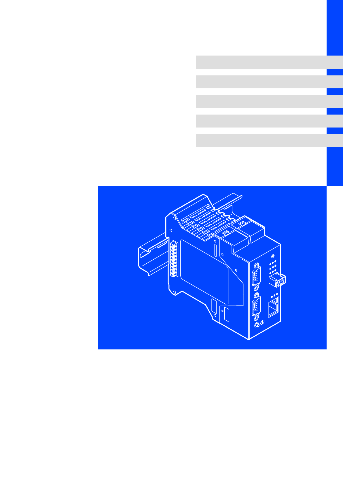
Hardware Manual
ETC Motion Control
L
ETCxxxxx
DIN rail modules and PCI card
l
Page 2

© 2006 Lenze Drive Systems GmbH, Hans−Lenze−Straße 1, D−31855 Aerzen
No part of this documentation may be reproduced or made accessible to third parties without written consent by Lenze Drive
Systems GmbH.
All information given in this documentation has been selected carefully and complies with the hardware and software
described. Nevertheless, deviations cannot be ruled out. We do not take any responsibility or liability for damages which might
possibly occur. Necessary corrections will be included in subsequent editions.
Page 3

Contents i
1 Preface and general information 5 . . . . . . . . . . . . . . . . . . . . . . . . . . . . . . . . . . . . . .
1.1 About this Manual 5 . . . . . . . . . . . . . . . . . . . . . . . . . . . . . . . . . . . . . . . . . . . . .
1.2 For which products is the manual valid? 6 . . . . . . . . . . . . . . . . . . . . . . . . . .
1.3 Legal regulations 7 . . . . . . . . . . . . . . . . . . . . . . . . . . . . . . . . . . . . . . . . . . . . . .
2 Technical data 8 . . . . . . . . . . . . . . . . . . . . . . . . . . . . . . . . . . . . . . . . . . . . . . . . . . . . . .
2.1 General data and operating conditions 8 . . . . . . . . . . . . . . . . . . . . . . . . . . .
2.2 Rated data 9 . . . . . . . . . . . . . . . . . . . . . . . . . . . . . . . . . . . . . . . . . . . . . . . . . . .
2.2.1 Standard device 9 . . . . . . . . . . . . . . . . . . . . . . . . . . . . . . . . . . . . . . .
2.2.2 Power supply unit 10 . . . . . . . . . . . . . . . . . . . . . . . . . . . . . . . . . . . . .
2.2.3 Bus termination module 10 . . . . . . . . . . . . . . . . . . . . . . . . . . . . . . . .
2.2.4 Input module 11 . . . . . . . . . . . . . . . . . . . . . . . . . . . . . . . . . . . . . . . . .
2.2.5 Output module 12 . . . . . . . . . . . . . . . . . . . . . . . . . . . . . . . . . . . . . . .
2.2.6 Analogue module 13 . . . . . . . . . . . . . . . . . . . . . . . . . . . . . . . . . . . . . .
3 Device description 14 . . . . . . . . . . . . . . . . . . . . . . . . . . . . . . . . . . . . . . . . . . . . . . . . . .
3.1 System overview 14 . . . . . . . . . . . . . . . . . . . . . . . . . . . . . . . . . . . . . . . . . . . . . .
3.1.1 Examples for an automation system 14 . . . . . . . . . . . . . . . . . . . . .
3.1.2 Layout example for an ETC island 16 . . . . . . . . . . . . . . . . . . . . . . . .
3.1.3 Set node address 18 . . . . . . . . . . . . . . . . . . . . . . . . . . . . . . . . . . . . . .
3.2 Control in top hat rail design (ETCHx) 19 . . . . . . . . . . . . . . . . . . . . . . . . . . . .
3.2.1 Serial interface 21 . . . . . . . . . . . . . . . . . . . . . . . . . . . . . . . . . . . . . . . .
3.2.2 CAN interface 22 . . . . . . . . . . . . . . . . . . . . . . . . . . . . . . . . . . . . . . . . .
3.2.3 Ethernet interface 24 . . . . . . . . . . . . . . . . . . . . . . . . . . . . . . . . . . . . .
3.2.4 Watchdog (WDOG) 25 . . . . . . . . . . . . . . . . . . . . . . . . . . . . . . . . . . . .
3.3 Control as PCI insert card (ETCPx) 26 . . . . . . . . . . . . . . . . . . . . . . . . . . . . . . . .
3.3.1 Serial interface 27 . . . . . . . . . . . . . . . . . . . . . . . . . . . . . . . . . . . . . . . .
3.3.2 CAN interface 29 . . . . . . . . . . . . . . . . . . . . . . . . . . . . . . . . . . . . . . . . .
3.3.3 Configuration and Watchdog 30 . . . . . . . . . . . . . . . . . . . . . . . . . . .
3.4 Module 32 . . . . . . . . . . . . . . . . . . . . . . . . . . . . . . . . . . . . . . . . . . . . . . . . . . . . . .
3.4.1 Power supply unit 32 . . . . . . . . . . . . . . . . . . . . . . . . . . . . . . . . . . . . .
3.4.2 Bus termination module 35 . . . . . . . . . . . . . . . . . . . . . . . . . . . . . . . .
3.4.3 Input module 37 . . . . . . . . . . . . . . . . . . . . . . . . . . . . . . . . . . . . . . . . .
3.4.4 Output module 41 . . . . . . . . . . . . . . . . . . . . . . . . . . . . . . . . . . . . . . .
3.4.5 Analogue module 45 . . . . . . . . . . . . . . . . . . . . . . . . . . . . . . . . . . . . . .
EDSTCXX EN 2.0
l 3
Page 4

Contentsi
4 Mechanical installation 47 . . . . . . . . . . . . . . . . . . . . . . . . . . . . . . . . . . . . . . . . . . . . . . .
4.1 Control and module for top hat rail mounting (ETCHx) 47 . . . . . . . . . . . . . .
4.1.1 Control ETCHx 49 . . . . . . . . . . . . . . . . . . . . . . . . . . . . . . . . . . . . . . . .
4.1.2 Module ETCHx 50 . . . . . . . . . . . . . . . . . . . . . . . . . . . . . . . . . . . . . . . .
4.1.3 Dismantling of control and module ETCHx 51 . . . . . . . . . . . . . . . . .
4.2 Control in PCI design (ETCPx) 52 . . . . . . . . . . . . . . . . . . . . . . . . . . . . . . . . . . .
4.2.1 Installing the PCI card in the PC 52 . . . . . . . . . . . . . . . . . . . . . . . . . .
5 Electrical installation 53 . . . . . . . . . . . . . . . . . . . . . . . . . . . . . . . . . . . . . . . . . . . . . . . . .
5.1 Installation according to EMC (installation of a CE−typical drive system) 53
5.2 CAN installation instructions 55 . . . . . . . . . . . . . . . . . . . . . . . . . . . . . . . . . . . .
5.2.1 Cable types for the CAN Bus 56 . . . . . . . . . . . . . . . . . . . . . . . . . . . .
5.2.2 Relationship between cable length and transfer rate 56 . . . . . . . .
5.2.3 Stub cables 57 . . . . . . . . . . . . . . . . . . . . . . . . . . . . . . . . . . . . . . . . . . .
5.3 Initial switch−on 58 . . . . . . . . . . . . . . . . . . . . . . . . . . . . . . . . . . . . . . . . . . . . . . .
6 Troubleshooting and fault elimination 59 . . . . . . . . . . . . . . . . . . . . . . . . . . . . . . . . .
6.1 Status display 59 . . . . . . . . . . . . . . . . . . . . . . . . . . . . . . . . . . . . . . . . . . . . . . . .
6.2 Error management 62 . . . . . . . . . . . . . . . . . . . . . . . . . . . . . . . . . . . . . . . . . . . .
6.3 Module replacement 64 . . . . . . . . . . . . . . . . . . . . . . . . . . . . . . . . . . . . . . . . . . .
6.4 Battery replacement 65 . . . . . . . . . . . . . . . . . . . . . . . . . . . . . . . . . . . . . . . . . . .
7 Index 68 . . . . . . . . . . . . . . . . . . . . . . . . . . . . . . . . . . . . . . . . . . . . . . . . . . . . . . . . . . . . .
l 4
EDSTCXX EN 2.0
Page 5

Preface and general information
1 Preface and general information
The ETC Motion Control as the leading element of automation is together
with the Lenze drive controllers and motors an optimal system solution for
the control of movements.
In the ETC system both compact controls for installation on top hat rails and
PC insert cards are available. In both hardware designs either a NC or a MC
core can be supplied. The programming of the NC is carried out in accordance
with DIN 66025 (G code), that of MC in accordance with PLCOpen. Both
controls also include a PLC with is programmed in accordancd with 61131−3.
The control system is complemented by the corresponding I/O
subassemblies.
The communication with the drives via CAN or to the PC level via Ethernet
TCP/IP is also integrated into the ETC.
About this Manual
1
1.1
1.1 About this Manual
Target group
Contents
Further information
This manual is intended for all those who plan, install, program or
commission the ETC Motion Control System under the "NC" operating
system.
The ETC device manual contains information on the following topics:
ƒ Technical data
ƒ Structure and function of the system components including interface
ƒ Mounting, connecting and maintaining system components
This manual is complemented by the software manuals "MC operating
system" and "NC operating system", which provide important information
for the programmer and commissioner.
I Tip!
description
Current documentation and software updates concerning Lenze
products can be found on the Internet in the "Services &
Downloads" area under
http://www.Lenze.com
EDSTCXX EN 2.0
l
5
Page 6

1
1.2
Preface and general information
For which products is the manual valid?
1.2 For which products is the manual valid?
Standard device
ETC xx 0 xx 1A 10
Product
Version
HM = top hat rail, MC core
PM = PCI insert card, MC core
HC = DIN rail, CNC core
PC = PCI insert card, CNC core
ETCHx0xx
Number of axes
02 = 2 axes
04 = 4 axes
08 = 8 axes
12 = 12 axes
Hardware version
Modules
Software version ETCPx0xx
ETCH xxxx 1A 10
Product
N003 = power supply unit
T000 = bus termination module
I008 = 8 dig. inputs
I016 = 16 dig. inputs
U008 = 8 dig. outputs
U016 = 16 dig. outputs
A022 = 2 analogue inputs and outputs
each
ETCHxxxx
Hardware version
Software version
6
l
EDSTCXX EN 2.0
Page 7

1.3 Legal regulations
Preface and general information
Legal regulations
1
1.3
Marking
Manufacturer
CE conformity
Application as intended
The components of the ETC Motion Control System are clearly marked by the
contents of the nameplate.
Lenze Drive Systems GmbH, Postfach 101352, D−31763 Hameln
Compliant with EC Directive "Electromagnetic compatibility"
Components of the ETC Motion Control System
ƒ must only be operated under the operating conditions described in the
ETC Hardware Manual.
ƒ are not approved for the use in explosive environments.
ƒ comply with the protection requirements of the EC Directive "Low
voltage".
ƒ are no machines in the sense of the EC Directive "Machines".
ƒ are no household appliances, as components they are intended for
industrial use only.
The downstream user is responsible for ensuring that the EC Directives are
complied with in machine use.
Any other use shall be deemed inappropriate!
Liability
Warranty
The information, data and notes in this manual were up to date at the time
of printing. No claims for the modification of systems and components that
have already been supplied may be made on the basis of the specifications,
illustrations and descriptions in this manual.
No liability is accepted by Lenze as to the suitability of any of the procedures
or circuit recommendations included here.
The information in this manual describe the properties of the products
without guaranteeing them. No liability will be accepted for damage or
disturbance caused by:
ƒ ignoring this manual
ƒ unauthorised alterations to the components of the ETC Motion Control
System
ƒ operating errors and incorrect working on or with the ETC Motion
Control System
See terms of sales and delivery of Lenze Drive Systems GmbH.
Report any claims under warranty to Lenze immediately on discovery of the
defect or fault. The warranty is void in all cases where liability cannot be
established.
EDSTCXX EN 2.0
l
7
Page 8

2
2.1
Technical data
General data and operating conditions
2 Technical data
2.1 General data and operating conditions
Type
Labelling and approval CE (compliance with the EMC Directive)
Climatic conditions
Storage 1 K3 per IEC/EN 60721−3−2
Temperature −20 °C ... +60 °C; D
Transport 2 K3 per IEC/EN 60721−3−2
Temperature −20 °C ... +60 °C; D
Operation
Atmospheric pressure 860 hPa to 1060 hPa
Rel. humidity 8 % ... 80 % (non condensing)
Vibration resistance
Shock (10 ms) max. 5 G
Vibration (5 ... 100 Hz) max. 0.5 G
Noise immunity EN50082−1 = severity 3
Noise emission EN50082−2 = limit value B
Packaging Dustproof packaging
Protection category IP20 IP00
Installation position vertical −
Installation clearances top and bottom 80 mm −
1)
Temperature −0 °C ... +50 °C; D
above 1000 m site altitude permissible temperature reduced by 1 K/300 m
1)
At maximum load, vertical installation and sufficient convection
ETCHx ETCPx
= 20 K/h
max
= 20 K/h
max
3 K3 per IEC/EN 60721−3−2
= 10 K/h
max
8
l
EDSTCXX EN 2.0
Page 9

Technical data
Rated data
Standard device
2.2 Rated data
2.2.1 Standard device
Type ETCHx ETCPx
Use Control (top hat rail design) Control (PCI insert card)
Weight 235 g 300 g
Dimensions (W x H x D) 100 x 45 x 115 mm 130 x 23 x 190 mm
Supply voltages:
Feed (external) typ. 24 V DC
5 V DC output on ME bus typ. 5.0 V, min. 4.75 V, max. 5.25 V DC
24 V DC output on ME bus typ. 24 V, min. 18 V, max. 32 V DC
Power loss max. 3 W
Power recovery up to max. ±32 V possible at the connection terminals
Potential isolation:
to CAN via optocoupler
to process level via optocoupler
Fuse:
24 V DC output on ME bus Front panel fuse
5 V DC output Short−circuit proof via DC/DC converter
Protection:
Feed against polarity reversal
5 V and 24 V supply against short circuit and polarity reversal
2
2.2
2.2.1
EDSTCXX EN 2.0
l
9
Page 10

2
2.2
2.2.2
Technical data
Rated data
Power supply unit
2.2.2 Power supply unit
Type
Use Power supply module
Weight 150 g
Dimensions (H x W x D) 99 mm x 22.5 mm x 114.5 mm
Supply voltages:
Feed (external) typ. 24 V DC
5 V DC output on ME bus typ. 5.0 V DC (4.75 ... 5.25 V DC)
24 V DC output on ME bus typ. 24 V DC (18 ... 32 V DC)
Power cunsumption at max.
output current:
Feed 18 V DC max. 3.2 A
Feed 24 V DC max. 2.9 A
Feed 32 V DC max. 2.7 A
Output current
5 V DC output on ME bus max. 3.0 A
24 V DC output on ME bus max. 2.0 A
Power loss max. 83 W
Power recovery up to max. ±32 V possible at the connection terminals
Potential isolation
between 5 V DC output and
24 V DC input
Fuse:
24 V DC output on ME bus Front panel fuse
5 V DC output Short−circuit proof via DC/DC converter
Protection
Feed against polarity reversal
5 V and 24 V supply against short circuit and polarity reversal
ETCHN003
500 V
2.2.3 Bus termination module
Type
Use Termination module or transfer module for internal CAN Bus (CAN1)
Weight 90 g
Dimensions (H x W x D) 99 x 17.5 x 114.5 mm
ETCHT000
10
l
EDSTCXX EN 2.0
Page 11

2.2.4 Input module
Technical data
Rated data
Input module
2
2.2
2.2.4
Type ETCHI008
Use 8 channel input module 16 channel input module
Weight 120 g 215 g
Dimensions (H x W x D) 99 x 22.5 x 114.5 mm 99 x 45.0 x 114.5 mm
Switching voltage of the inputs typ. 24 V DC (18 ... 32 V DC) via ME bus
Logical voltage typ. 5V DC ( 4.75 ... 5.25 V DC) via ME bus
Power loss typ. 3.0 W typ. 4.7 W
Input type digital current drawing inputs
Voltages of state "1" 11.0 to 32.0 V DC
Voltages of state "0" −3 to +5 V DC
Min. input current per channel 3 mA
Max. input current per channel 12 mA
Max. switching frequency at the
input
Input indication per input one LED, connected in series to the input terminal
Electrical isolation the inputs are connected via the joint earthing potential
24 V DC PTC thermistor
Logic component SMD time−lag fuse 500 mA
Power recovery up to max. +32 V at one input/output terminal possible
Protection Feed protected against polarity reversal.
Potential isolation 500 V DC (between logic component and input terminal)
approx. 250 Hz
ETCHI016
EDSTCXX EN 2.0
l
11
Page 12

2
2.2
2.2.5
Technical data
Rated data
Output module
2.2.5 Output module
Type ETCHU008
Use
Weight 145 g 215 g
Dimensions (H x W x D) 99 x 22.5 x 114.5 mm 99 x 45.0 x 114.5 mm
Supply voltages:
Supply voltage outputs typ. 24 V DC (18 ... 32 V DC) external feed
Supply voltage control typ. 24 V DC (18 ... 32 V DC) via ME bus
Logical voltage typ. 5.0 V DC (4.75 ... 5.24 V DC) via ME bus
Power loss:
4 outputs switched on typ. 1.0 W −
8 outputs switched on typ. 1.8 W typ. 1.5 W
16 outputs switched on − typ. 3.0 W
Outputs:
Switching voltage typ. 24 V DC (18 ... 32 V DC) external feed
Load characteristic resistive, inductive, capacitive
Continuous current per
channel
Current per channel for 1 sec 700 mA
Voltage drop for switch max. 400 mV at 500 mA
Min. voltage at the output
terminals
Parallel switching of several
outputs
Switching frequency of the
switches
Restart automatically after short circuit (with control present)
Short circuit peak current transient 4.0 A per channel (limited in the switch)
automatic restart current
with sustained short circuit
at output
Output indication on LED per output at the switch output
Initial state witch missing
control switched off by
Intermediate storage of the
control signal
Electrical isolation The output earth conductors are connected to each other
Fuse:
Switch Per 4 outputs each time−lag Microfuse 4 A; optionally pluggable
Switch triggering SMD time−lag fuse 500 mA
Logic component SMD time−lag fuse 500 mA
Power recovery up to max. + 32 V DC at one output terminal possible
Potential isolation 500 V DC (between logic component and input terminal)
Protection l The outputs are protected against overheating, short circuit and polarity reversal up to
±32 V DC.
l Additional fire protection with 4 A fuse. Suppressor diode (36 V) parallel to each switch
output.
l Series diode between switch output and output terminal.
l RESET trigger with drop in logical voltage.
Semiconductor switch against 24 V DC (High Side Switches)
8 channel output module 16 channel output module
max. 500 mA
Supply voltage – 1.0 V (at full load 0.5 A)
possible
max. 250 Hz at resistive load
3.0 A pulsed (with control present) switched off
logical component
no
ETCHU016
12
l
EDSTCXX EN 2.0
Page 13

2.2.6 Analogue module
Technical data
Rated data
Analogue module
2
2.2
2.2.6
Type
Use 2 channel analogue input/output module, 0 V or −10 V ... +10 V
Weight 125 g
Dimensions (H x W x D) 99 x 22.5 x 114.5 mm
Supply voltages:
Control voltage (sensor feed) typ. 24 V DC (18 ... 32 V DC) feed via ME bus
Logical voltage typ. 24 V DC (18 ... 32 V DC) feed via ME bus
Power loss max. 6.2 W
Input:
Input impedance > 500 kOhm
Measuring range
(switchable)
Voltage at the input max. 32 V
Resolution 12 Bit
Conversion method successive approximation
Value of the LSB 2.5 mV for measuring range 0 ... 10 V or
5 mV for measuring range −10 V ... +10 V
Inaccuracy max. 50 mV for measuring range 0 ... 10 V or max. 100 mV for measuring range −10 V ... +10 V
Scanning frequency 205 Hz
Filters analogue low−pass filter of 1st degree with a limiting frequency of 30 Hz, digital configurable
Permitted sensor types Active and passive sensors
Sensor feed, sensor current 10 V regulated, max. 10 mA
Permitted connection cables Shielded cables; shield placed before the module
Output:
Output range (switchable) 0 ... 10 V or −10 ... +10 V
max. 0 ... 10.238 V or −10.238 V ... +10.238 V
Output current max. 2 mA
Min. load 5 kOhm
Resolution 12 Bit
Value of the LSB 2.5 mV or 5 mV
Inaccuracy max. 50 mV or 100 mV
Output rate min. 10 ms continually, min. 5 ms continually (digital input filter switched off)
Filters analogue low−pass filter of 1st degree with a limiting frequency of approx. 730 Hz
Permitted connection cables Shielded cables, shield placed before the module
Power recovery max. ±32 V at an input/output terminal
Potential isolation 500 V DC between ME bus and input/output terminals
Fuse:
Logic component SMD time−lag fuse 500 mA
System voltage SMD time−lag fuse 1500 mA
Protection l 24 V system voltage is protected by a definite plug−in direction in the housing.
l 5 V bus voltage is protected by a definite plug−in direction in the housing.
l Sensor supply is protected against short circuit, overcurrent and negative feed
l Current and voltage inputs (optional) are protected against voltages up to 32 V
l Input protection via high resistance voltage dividers
l Protection of the sensor feed via series diodes and active current limitation
l ESD protection via Transil diodes at PE
l Output protection via passive current limitation
l Series and parallel diodes, short−circuit proof
l ESD protection via Transil diodes at PE
ETCHA022
0 ... 10 V or –10 V ... +10 V
low−pass filter
EDSTCXX EN 2.0
l
13
Page 14
3
3.1
3.1.1
Device description
System overview
Examples for an automation system
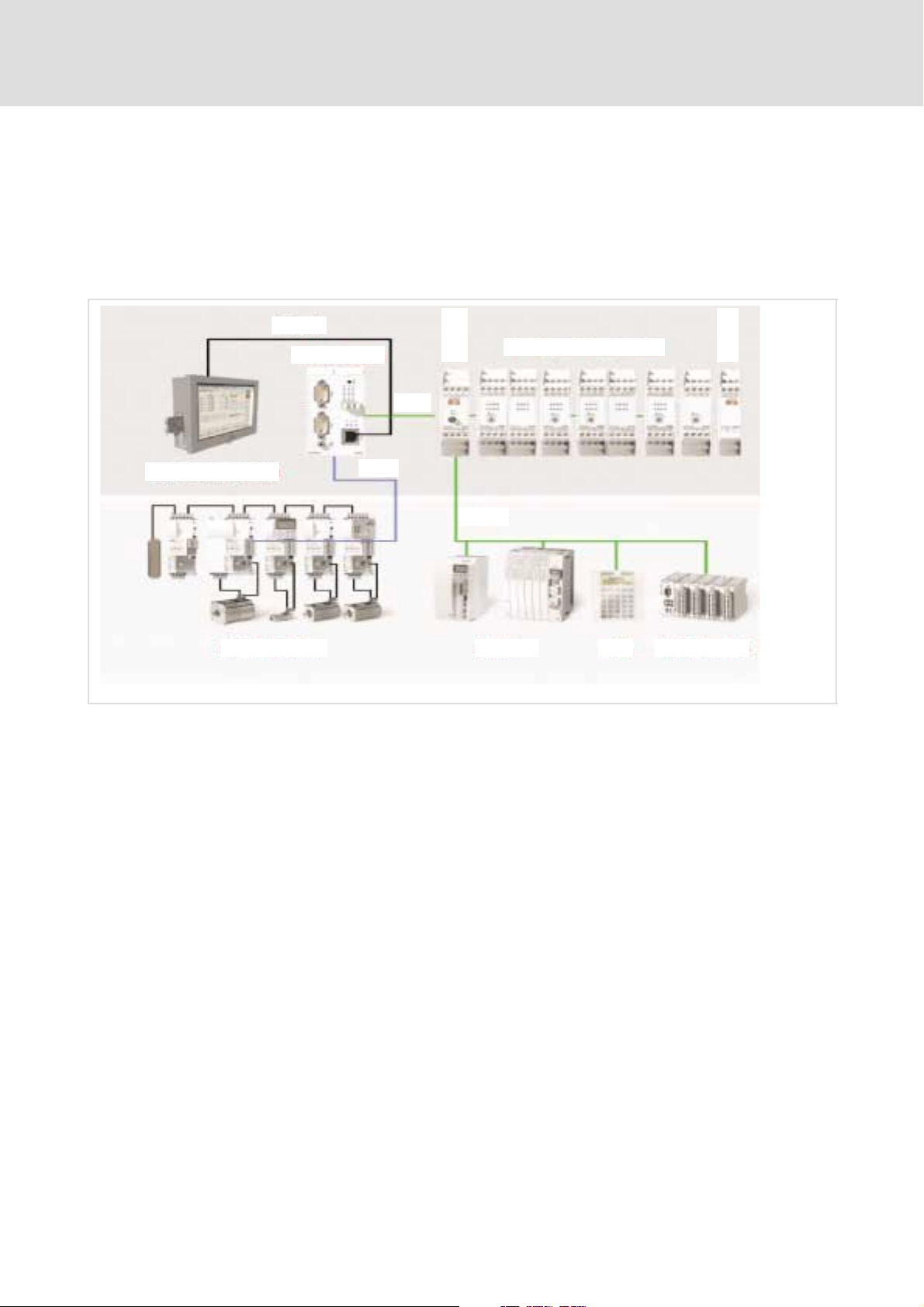
3 Device description
3.1 System overview
3.1.1 Examples for an automation system
Ethernet
ETCHx
CAN1
ETCHN003
ETC-System Components
ETCHT000
ETCHx / ETCPx
IPC with ETCPx
ECS/MCS-System Drives HMI I/O-System IP20
CAN2
CAN-I/O
ETCM001
The core of the automation system is the ETC control in the top hat rail design
(ETCHx) or as PCI insert card (ETCPx).
The top hat rail design ETCHx is normally used in a so−called ETC island
(¶ 16); it communicates via Ethernet with the applications on the IPC (or
standard PC).
The ETCPC is inserted into the IPC (or standard PC) and communicates with
the applications via the PCI bus.
Both designs have two separate CAN busses:
14
ƒ At CAN1 bus (or also ME bus) the I/O modules and any operating
components are connected. Third party devices must comply with teh
DS401 profile of the CANopen specification.
ƒ The drives (e.g. the ECS compact servo) are connected to the connection
for the Motion CAN bus (CAN2) at the front plate. External drives must
comply with the profile DS402 of the CANopen specification and in
particular support the "Interpolated Position Mode".
l
EDSTCXX EN 2.0
Page 15

Device description
System overview
Examples for an automation system
To carry out its allocated control function the ETC control needs various
programs which are transferred from the IPC (or standard PC):
ƒ Operating system or firmware of the control (e.g. ETCHC.rsc)
ƒ PLC programs (e.g. SPSDummy.prg)
ƒ CNC programs; i.e. cycle and DIN programs (e.g. 9000.zyk or
Nikolaus.din)
3.1
3.1.1
3
IPC
The ETC control is operated and maintained via the IPC (or standard PC). The
following applications might run on it:
ƒ Windows 2000 or XPoperating system
ƒ Terminal program (e.g. HyperTerminal) for establishing the Ethernet
connection between IPC and ETCHx control and for the configuration of
the ETCHx control via the monitor interface (e.g. firmware update). This
is not required for the ETCPx.
ƒ ETC−MMI gateway as communications program between Windows
applications and the ETC control.
ƒ Lenze ETC−MMI for the configuration, operation and monitoring of the
ETC control and for creating CNC programs.
ƒ CoDeSys development environment for the creation and testing of PLC
programs.
) Note!
An external keyboard is required at the IPC for commissioning. It
is not required for normal operation.
EDSTCXX EN 2.0
l
15
Page 16
3
3.1
3.1.2
Device description
System overview
Layout example for an ETC island
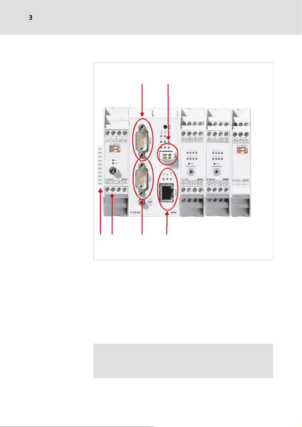
3.1.2 Layout example for an ETC island
ETCHN003
10
ETCHx004
ETCHI016
ETCHI008
ETCHT000
2345
ETCM002
0 Serial interface (RS232)
1 Watchdog (e.g. for emergency stop chain)
2 Ethernet
3 Motion CAN bus (CAN2)
4 24 V supply
5 ME bus (CAN1)
ETCHN003: Power supply unit for the supply of the ETC island and ME bus
connection
ETCHx004: ETC Motion Control for 4 axes (control)
ETCHIxxx: Input module with 16 or 8 digital inputs
ETCHT000: ME bus terminator module
) Note!
To terminate the ME bus DIP switch 1 must be set to ON at both
the power supply unit ETCHN003 and the bus terminator
module ETCHT000.
16
l
EDSTCXX EN 2.0
Page 17
Control
CAN Master
Device description
System overview
Layout example for an ETC island
CAN bus terminated
3
3.1
3.1.2
1. isolated system
max. CAN bus length
2. isolated system 3. isolated system
ETC024
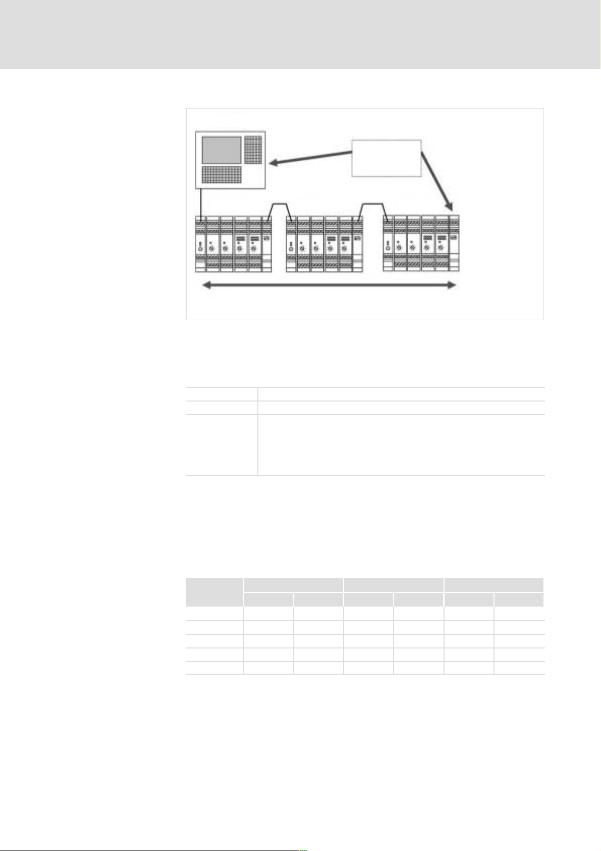
Several ETCHx islands can be connected to form a complete system. Please
note the maximum permissible cable length per CAN level dependent on the
Baud rate (¶ 56). The maximum number of modules in one ETCHx island is
limited by the following constraints.
CAN Bus max. 127 modules
Module address max. 16 modules of the same type
Power supply
unit
In practice the capacity of the power supply unit is the decisive factor for
the maximum number of modules in an island. The current consumption of
the individual modules both via the 24 V and the 5 V supply is relevant and
must be taken into account.
Typically 15 modules can be supplied with one power supply unit
ETCHN003.
The power consumption of the individual modules fromthe 5 V voltage
produced in the power supply unit is shown in the following table.
EDSTCXX EN 2.0
The figure for "typ." refers to the 24 V supply voltage and with a high signal
being present at half the digital inputs and outputs.
The figure for "max." refers to the 32 V supply voltage and an operating state
with maximum power consumption.
Module
ETCHU008 95 mA 180 mA 15 mA 30 mA 30 mA 80 mA
ETCHU016 130 mA 240 mA 25 mA 55 mA 60 mA 160 mA
ETCHI008 70 mA 90 mA 90 mA 105 mA − −
ETCHI016 90 mA 120 mA 145 mA 175 mA − −
ETCHA022 150 mA 160 mA 60 mA 80 mA − −
5 V internal bus 24 V internal bus 24 V external (no load)
typ. max. typ. max. typ. max.
ETCHU008/016: Outputs fed externally.
ETCHI008/016: Eingänge intern gespeist.
The ampacity of the cables and plug−in connectors of the internal system bus
is at least 8 A (per cable). The direct plug−in connections between housing
and PCB can accept a load of 3 A.
l
17
Page 18
3
3.1
3.1.3
Device description
System overview
Set node address
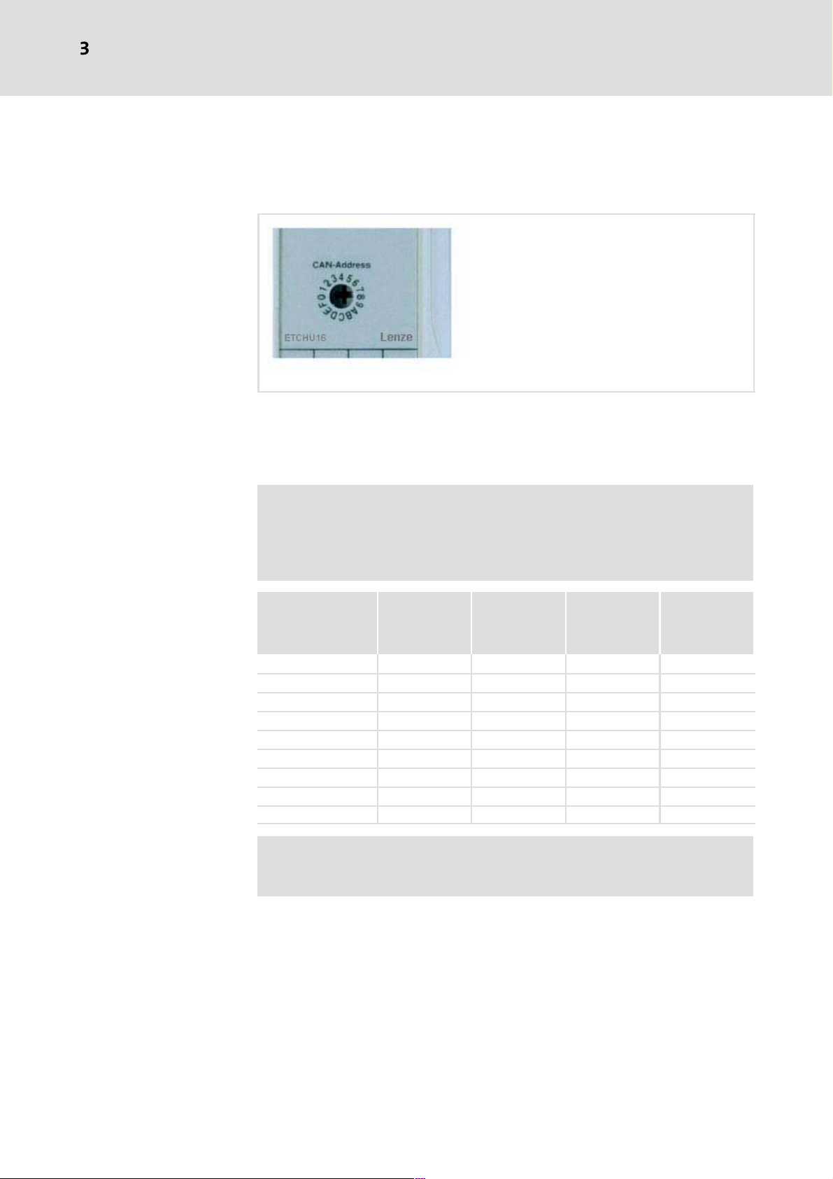
3.1.3 Set node address
Every ETCHx I/O module in a line represents a separate node at CAN1 bus and
must be set up with a unique node address.
ETC025
The node address is set via a front Hex switch (4 low value address bits) and
via permanently wirded bridges within the housing (3 high value address
bits). This means that a maximum of 16 modules are possible within a
module type.
) Note!
Some modules have internal codings switches instead of the
permanently wired bridges for the optional modification of the
high value address bits.
Module type High value
address bits
permanently
wired
CAN Bus Master −− −− 00 0
−− −− −− 01 H…0 FH 1 ... 15
ETCHU 10 H 0…FH 10 H…1 FH 16 ... 31
20 H 0…FH 20 H…2 FH 32 ... 47
ETCHA 30 H 0…FH 30 H…3 FH 48 ... 63
40 H 0…FH 40 H...4 FH 64 ... 79
ETCHI 50 H 0…FH 50 H…5 FH 80 ... 95
60 H 0…FH 60 H ... 6 FH 96 ... 111
70 H 0…FH 70 H ... 7 FH 112 ... 127
Low value
address bits
adjustable at
the front
Adjustable
node address
(hex)
Adjustable
node address
(decimal)
) Note!
All modules at the CAN bus must have a different node address.
18
l
EDSTCXX EN 2.0
Page 19
3.2 Control in top hat rail design (ETCHx)
Device description
Control in top hat rail design (ETCHx)
3
3.2
Description
Features
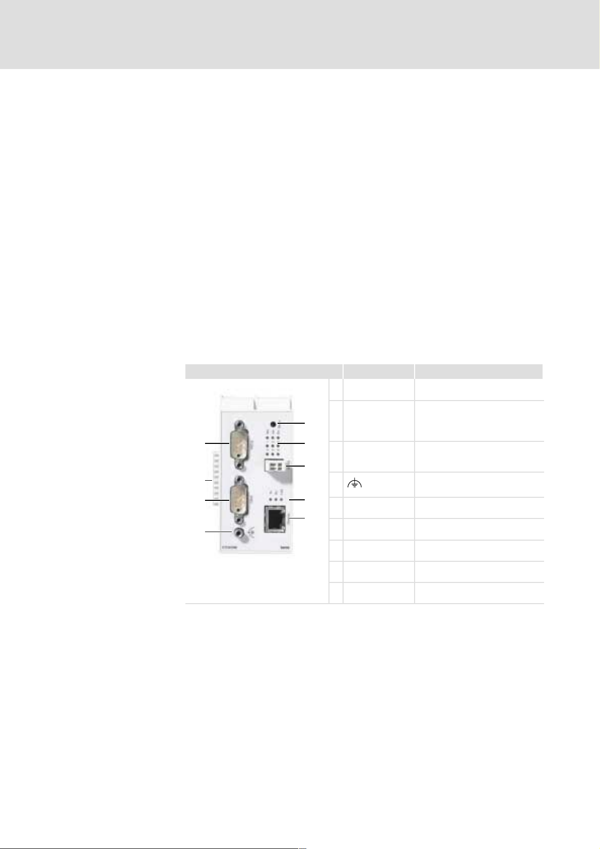
Elements
The ETCHx is a control for top hat rail assembly. Up−to−date communication
interfaces like Ethernet TCP/IP for networking and PC−MMI connection and
dual CANopen for the connection of field bus terminals or digital drive
amplifiers make the ETCHX ideal for use in machines with a distributed
control structure.
The connection to other modules is via the integrated ME bus.
ƒ 32 Bit MPC 555 Microcontroller
ƒ 4 MByte SRAM (with battery buffer; of which 12 KByte are available to
the PLC as remanent variable memory)
ƒ 2 MB Flash PROM
ƒ 2 CAN interfaces, 2 serial interfaces
ƒ 1 Ethernet TCP/IP interface
ƒ Watchdog
Designation Function
0 RS232 1st serial interface
1 ME bus Supply of the connected
4
modules and CAN1 bus for I/O
modules
0
5
2 CAN2 CAN2 bus for drives and
2nd RS232 interface
6
1
2
3 Functional earth (PE)
7
4 reset initialise control
8
5 LED 1 Status indication
3
6 WDOG Watchdog output
7 LED 2 Ethernet communication
8 Ethernet TCP/IP interface
ETC003
The control includes a battery for the SRAM.
The CAN1 interface is only present on the internal "ME bus". It can be
connected either to the power supply unit ETCHN003 or the bus termination
module ETCHT000.
EDSTCXX EN 2.0
l
19
Page 20

3
3.2
Device description
Control in top hat rail design (ETCHx)
Organisation of memory
4 MByte static SRAM (32 Bit RAM) and 2 MB Flash PROM are available.
ETCHC: The firmware has a memory requirement of 1 ... 1.5 MB SRAM and
1 MB Flash PROM. This means that the user has 2.5 ... 3 MB SRAM and 1 MB
Flash PROM available. This is sufficient for e.g. typically 128 NC sentences
(preprocessing buffer), 512 kB PLC program, 128 kB PLC data and 1 MB SPV
memory (DIN program memory).
ETCHM: The firmware has a memory requirement of 1 MB SRAM and 1 MB
Flash PROM. This means that the user has 3 MB SRAM and 1 MB Flash PROM
available. Verfügung. This is sufficient for e.g. typically 2000 kB PLC program
and 1000 kB PLC data.
The memory allocation can be configured by the user.
20
l
EDSTCXX EN 2.0
Page 21
Device description
Control in top hat rail design (ETCHx)
Serial interface
3
3.2
3.2.1
3.2.1 Serial interface
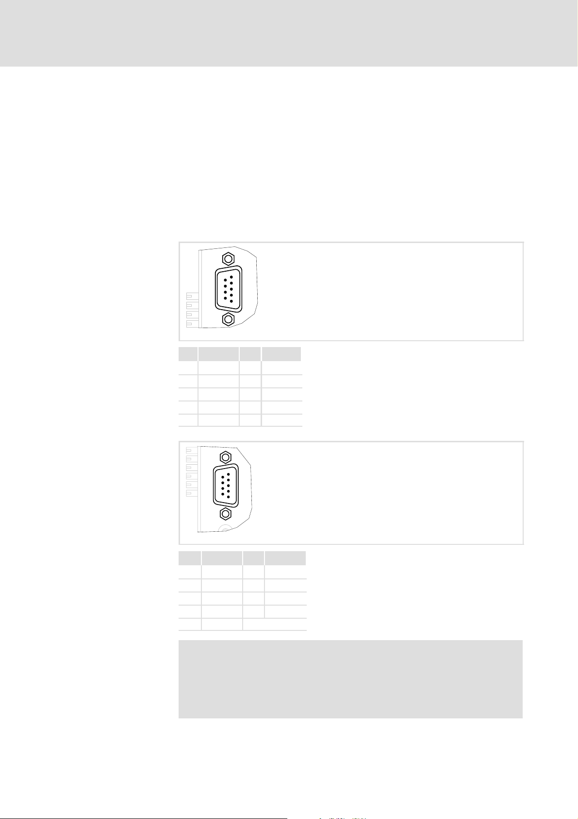
Connector allocation RS 232
(9−pole D−Sub pin)
The subassembly features two serial interfaces of the RS232 standard. The
signals of the first serial interface are connected to the RS232 plug
connector, and those of the second interface to the free contacts of the CAN2
plug connector. There are no hardware handshake signals for the second
interface.
The PLC programming environment and that of the internal monitors is
operated with 115 kBaud via the "RS232 connector. A client−specific PLC
program can control both interfaces.
1
6
RS232
9
5
ETC029
Pin Signal Pin Signal
1nc 6 DSR
2 RxD 7 RTS
3 TxD 8 CTS
4 DTR 9 nc
5 GND
Connector allocation (9−pole
D−Sub pin)
1
6
CAN2
9
5
Pin Signal Pin Signal
1 RxD 2 6
2 7
3 8 TxD 2
4 GND 9
5
) Note!
Use shielded cables and connector shells from metal or
metallised plastic for connecting the serial interfaces. The cable
shield must be connected conductively to both sides of the
connector shell.
ETC030
EDSTCXX EN 2.0
l
21
Page 22

3
3.2
3.2.2
Device description
Control in top hat rail design (ETCHx)
CAN interface
3.2.2 CAN interface
CAN2 (drives)
Connector allocation (9−pole
D−Sub pin)
Drives approved by Lenze can be connected to the CAN2 interface.
The CAN2 interface is connected to the 9−pole D−Sub connector with
standard connector allocation via the CAN driver (electrically isolated). The
isolation voltage to the computer is 500 V.
The CAN2 bus must be terminated in the connector with a 120 Ohm resistor.
A Can high−speed interface is implemetned in accordance with the ISO/DIS
11898 standard. The ETCHx is implemented as CAN Master.
1
6
CAN2
9
5
ETC030
Pin Signal Pin Signal
1 6 GND
2 CAN_L 7 CAN_H
3 GND 8
4 9 nc
5 Shield
ME bus with CAN1 (I/O)
Devices can be connected to the CAN1 bus which are triggered via the PLC
and support the CANopen profile DS 301. The bus lines can be picked up
directly at the bus connection if required.
The CAN1 interface is connected to the ME bus via CAN driver with electrical
connection to the PC. If the ETCHx is used at the CAN bus start or end, the bus
must be terminated with a terminating resistor of 120 Ohm (DIP switch on
the power supply unit ETCHN003 or the bus termination module ETCHT000).
To connect a block of interconnected modules to other CAN statiions the
CAN bus signals are directed to the upper terminals in the power supply
module ETCHN003 and the bus terminator module ETCHT000.
22
l
EDSTCXX EN 2.0
Page 23

Connector allocation for ME
bus with CAN1 (Phoenix
Mini−Combicon)
ME
Pin Signal Pin Signal
1 GND 5 V 6 CAN_H
2 GND 5 V 7 CAN_L
3 +5 V 8 PE
4 +5 V 9 +24 V
5 CAN_Gnd 10 GND 24 V
Device description
Control in top hat rail design (ETCHx)
CAN interface
3
3.2
3.2.2
ETC010
) Note!
The physical connection can be checked at any point of the CAN
bus using an Ohmmeter. All supply voltages must be switched
off for the measurement.
The measured resistance between the signals CAN_H and CAN_L
must be approx. 60 Ohm. The resistance between CAN_L and
GND and btetween CAN_H and GND must be "infinitely" large.
Other values can be measured as a result of a short circuit in the
signals or a reversal of the connections.
CiA−DS−102−1 and CiA DR−303−1 describes the plug−in connectors
and cables used and the supported bit rates.
EDSTCXX EN 2.0
l
23
Page 24

3
3.2
3.2.3
Device description
Control in top hat rail design (ETCHx)
Ethernet interface
3.2.3 Ethernet interface
The interface is used to connect a PC terminal or to integrate the control
within a network. It is designed as a RJ45 plug−in connector. The cabling type
is 10 BASE−T.
Connector allocation (8−pole
RJ45 connector)
Tx
Rx
Link
Ethernet
Pin Signal Pin Signal
1 TxD+ 6 RxD−
2 TxD− 7 nc
3 RxD+ 8 nc
4 nc
5 nc
ETC036
The LEDs on the front plate indicate the following states:
Tx, Rx Data transfer via the interface
LNK Result of the internal 10 BASE−T Link Integrity Test. It illuminates as soon as
an Ethernet connection has been established.
) Note!
If a point−to−point connection between control and PC terminal
is being set up, a "cross−over" cable must be used.
24
l
EDSTCXX EN 2.0
Page 25

3.2.4 Watchdog (WDOG)
The Watchdog circuit is used to monitor the processor and switches the
linked outputs off as soon as they are no longer triggered.
2
WDOG
Device description
Control in top hat rail design (ETCHx)
Watchdog (WDOG)
3
3.2
3.2.4
1
Pin Signal
1 +24 V
2 out (max. 100 mA)
Conductor cross section: max 0.5 mm
2
ETC039
A Watchdog signal can be picked off from the WDOG connector. For this a
+24 V voltage must be connected to Pin 1. Unless the Watchdog has been
released, the voltage is connected through to Pin 2.
EDSTCXX EN 2.0
l
25
Page 26

3
3.3
Device description
Control as PCI insert card (ETCPx)
3.3 Control as PCI insert card (ETCPx)
Description
Features
Elements
The ETCPC includes the coupling to the PC via a PCI bus plug−in connector and
the complete MC or NC core plus a PlC computer core.
ƒ 32 Bit MPC 555 Microcontroller
ƒ 4 MByte SRAM (with battery buffer; of which 12 KByte are available to
the PLC as remanent variable memory)
ƒ 256 MB Flash PROM
ƒ 2 CAN interfaces, 2 serial interfaces
ƒ Watchdog
Designation Function
0 P1 1st Serial interface (RS232)
1 P2 2nd Serial interface (RS232)
5
2 J3 Lenze Service interface
3 J4 Lenze Service interface
6
4 J5 Lenze Service interface
0
1
4
3
2
:
5 Battery for SRAM
9
8
6 P7 Lenze Service interface
7 P5 Lenze Service interface
8 P6 CAN 2 (drives)
7
9 LEDs Status indication
Organisation of memory
P4 CAN 1 (I/O)
:
ETC004
4 MByte static SRAM (32 Bit RAM) and 256 kB Flash PROM are available. The
firmware has a memory requirement of 1 MB SRAM.
The firmware is read from the hard drive and written to the SRAM. This
means the user has 3 MB SRAM and 256 kB Flash available.
The memory allocation can be configured by the user.
26
l
EDSTCXX EN 2.0
Page 27

3.3.1 Serial interface
Device description
Control as PCI insert card (ETCPx)
Serial interface
The subassembly features two serial interfaces of RS232 standard. The can
be used for operating the PLC development environment, as monitor
interfaces and as client−specific PLC interface.
The signals are directed to 10−pole pin contact strips P1 and P2 and can be
connected via ribbon cables to the D−Sub plug connectors fitted to the card
slots or the PC housing openings.
The PLC programming environment can be operated at P1 with 115 kBaud
or via P2 with 38 kBaud. The monitor is actuated via P1.
A client−specific PLC program can operate both interfaces.
A standard null modem cable can be used to connect a PC. The handshake
cables (RTS, CTS) must be wired.
3.3
3.3.1
) Note!
Use shielded cables and connector shells from metal or
metallised plastic for connecting the serial interfaces. The cable
shield must be connected conductively to both sides of the
connector shell.
3
Connector allocation P1 and
P2 (10−pole pin contact strip)
P1 P2
2
2
10
1
9
Pin Signal Pin Signal
1nc6 CTS
2 DSR 7 DTR
3 RxD 8 nc
4 RTS 9 GND
5 TxD 10 nc
10
1
9
ETC032
EDSTCXX EN 2.0
l
27
Page 28

3
3.3
3.3.1
Connector allocation P2, user
interface(9−pole D−Sub pin)
Device description
Control as PCI insert card (ETCPx)
Serial interface
ETC033
Pin Signal Pin Signal
1nc6 nc
2 RxD 7 nc
3 TxD 8 nc
4 nc 9 nc
5 GND
Connector allocation P1,
monitor program (10−pole pin
contact strip)
ETC034
Pin Signal Pin Signal
1nc6 nc
2 nc 7 nc
3 TxD 8 nc
4 nc 9 GND
5 RxD 10 nc
Via the plug connector P1 the content of the DPR can be read and written to
using a monitor program. It also allows for a data backup of the system
parameters from the DPR to the Parameter EEPROM.
The interface for the monitor program requires the following settings:
Baud rate 9600
Data bits 8
Stop bits 1
Parity no
28
The monitor program only uses ASCII characters; CR, LF, BS, XON and XOFF
are used as control characters.
l
EDSTCXX EN 2.0
Page 29

3.3.2 CAN interface
Connector allocation P4 and
P6, CAN interface (9−pole
D−Sub pin)
Device description
Control as PCI insert card (ETCPx)
CAN interface
The two CAN Controllers are directed via CAN drivers to 9−pole D−Sub plug−in
connectors with standard connector allocation (electrically isolated).
Because theETCPx has only one plug−in connector per CAN channel, the
subassembly must either be connected to one of the two bus ends or it must
be integrated with the bus line using an adapter cable or node connector
(e.g. ERbic by ERNI).
If the ETCPx is positioned at the CAN bus start or end, a terminating resistor
can be added on the board via the jumpbers J7 and J10.
A CAN high−speed interface in accordance with the ISO/DIS 11898 standard
has been implemented. The ETCPCx is implemented as a CAN Master.
The CAN interface is electrically isolated from the computer. The isolation
voltage to the computer is 500 V.
3.3
3.3.2
3
CAN interface P4
P4
P6
Pin Signal Pin Signal
1 Reserved 6 Ground
2 CAN−Low 7 CAN−High
3 Ground 8 Reserved
4 Reserved 9 +U
5 Shield
P4
P6
ETC035
P4 allows for devices to be connected which are triggered by the PLC and
support the CANopen profile DS 301.
A maximum of 60 nodes can be connected electrically to the interface.
EDSTCXX EN 2.0
l
29
Page 30

3
3.3
3.3.3
Device description
Control as PCI insert card (ETCPx)
Configuration and Watchdog
CAN interface P6
P6 is a drive interface for the connection of drives which have been approved
by Lenze. Dependent on the control design up to 12 axes can be controlled.
) Note!
The physical connection can be checked at any point of the CAN
bus using an Ohmmeter. All supply voltages must be switched
off for the measurement.
The measured resistance between the signals CAN_H and CAN_L
must be approx. 60 Ohm. The resistance between CAN_L and
GND and btetween CAN_H and GND must be "infinitely" large.
Other values can be measured as a result of a short circuit in the
signals or a reversal of the connections.
CiA−DS−102−1 and CiA DR−303−1 describes the plug−in connectors
and cables used and the supported bit rates.
3.3.3 Configuration and Watchdog
J7
J38
J10
Jumper
J7 Terminating resistor CAN 1 closed
J10 Terminating resistor CAN 2 closed
J11 RESET PCI bus acts on ETCPx closed
J38 Wachtdog bridged
Function Standard settings
CAUTION! Attach J38 only for commissioning and test
J11
open
ETC037
30
l
EDSTCXX EN 2.0
Page 31

Device description
Control as PCI insert card (ETCPx)
Configuration and Watchdog
3
3.3
3.3.3
Watchdog OK signal
Jumper allocation J5, Serial
expansion bus (14−pole pin
contact strip)
The watchdog circuit is used to check the processor and switches off the
linked outputs as soon as they are no longer triggered.
The Watchdog OK signal is connected to Pin 10 of the pin contact strip J5. For
external use this signal must be edited via the corresponding drivers and an
electrical isolation.
The jumper J38 is to be used for test purposes. It releases the WDOG signal
constantly irrespective of the Watchdog. The Watchdog OK signal is
indicated by the illumination of an LED in the status display.
J5
214
113
ETC038
Pin Signal
1 GND
10 IO_WDOG
) Note!
The Watchdog signal is a standard TTL output. This output must
not be taken directly from the PC but must be edited via
corresponding drivers and electrical isolation.
EDSTCXX EN 2.0
l
31
Page 32

3
3.4
3.4.1
3.4 Module
3.4.1 Power supply unit
Device description
Module
Power supply unit
Description
Features
The module ETCHN003 is used for the power supply of an ETC island and
transfer module for the CAN bus with multiline system structure.
ƒ Input voltage 18 ... 30 V DC
ƒ Output voltage 5 V DC (max. 3 A) and 24 V DC (max. 2 A)
ƒ Short−circuit and undervoltage protection
ƒ CAN−BUS In
ƒ Bus terminator can be added
ƒ Transfer module for multiline module structure
) Note!
ƒ Only one power supply unit is possible per ME bus. The
attachment of serveral power supply units (parallel
connection) to one ME bus is not permitted.
ƒ The module is protected against short circuit and reverse
polarity. During a short circuit or overloading of the internal
24 V supply on the ME bus the power supply is interrupted.
ƒ The 5 V supply is protected by the internal protective circuit of
the DC/DC converter.
ƒ Each external connection is protected up to an electric
strength of +32 V. This protection effective for a faulty
connection of the module and only if the supply cable includes
a circuit braker 6 A Type B which will trigger, if necessary.
32
l
EDSTCXX EN 2.0
Page 33

Elements
9 ... 12
S1, S2
Device description
Module
Power supply unit
3
3.4
3.4.1
ME
LED 5 V, LED 24 V
F1
1 ... 4
Terminal Designation Meaning Comment
1 +24 V Voltage supply
2 0 V Reference potential
9 C_H CAN High
10 C_L CAN Low
11 C_Gd CAN signal earth
12, 3, 4 CAN shield potential, shielding Terminals bridged
S1 Switch for CAN bus termination On = termination with
F1 Fuse Plug−in Microfuse 5 A,
LED 5 V
LED 24 V
ME ME bus
Live LED 5 V and 24 V Illuminate if voltage is
To extend the ME bus
to external modules
internally
120 Ohm between C_H
and C_L
125 V (manufacturer
Wickmann No.
303−1500−042); pull to
replace
adequate
ETC007
EDSTCXX EN 2.0
l
33
Page 34

3
3.4
3.4.1
Device description
Module
Power supply unit
ME bus
Control and power supply unit are connected to each other via the ME bus
connector. The power supply unit is connected to the left of the control.
ME
ETC010
Pin Signal Pin Signal
1 GND 5 V 6 CAN_H
2 GND 5 V 7 CAN_L
3 +5 V 8 PE
4 +5 V 9 +24 V
5 CAN_Gnd 10 GND 24 V
Block diagram
2
0
0 front terminals
1 ME bus
1
ETC006
34
l
EDSTCXX EN 2.0
Page 35

Device description
Module
Bus termination module
3
3.4
3.4.2
3.4.2 Bus termination module
Description
The module ETCHT000 is used as a bus terminator for the internal CAN bus
or as a transfer module for a multiline system structure.
CAN terminator module: DIP switch 1 = ON
CAN transfer module: DIP switch 1 = Off
Elements
ME
13 ... 15
9 ... 11
S1, S2
Terminal Designation Signal Comment
9 C_H CAN High
10 C_L CAN Low
11 C_Gd CAN signal earth
13 ... 15 CAN shield potential, shielding Terminals bridged
S1 Switch for CAN bus termination On = termination with
S2 Without function
ME ME bus
To extend the ME bus
to external modules
internally
120 Ohm between C_H
and C_L
ETC011
EDSTCXX EN 2.0
l
35
Page 36

3
3.4
3.4.2
Block diagram
Device description
Module
Bus termination module
Klemmen
Klemmen
01
frontseitig
frontseitig
0 front terminals
1 ME bus
Signale
Signale
Klemmen
ME-Bus
ME-Bus
frontseitig
ETC012
36
l
EDSTCXX EN 2.0
Page 37

Device description
Module
Input module
3
3.4
3.4.3
3.4.3 Input module
Description
Features
Elements ETCHI008
The input modules ETCI008 (8 inputs) and ETCI016 (16 inputs) for the
connection of potential−free contacts (make−contacts) switch an available
24 V DC voltage to the respective input.
ƒ 8 or 16 digital inputs
ƒ 8 or 16 control LEDs
ƒ 2 cable connection for 24 V DC input signals
– decoupled via optocoupler
ƒ Module address selectable via rotary switch
13 ... 16
9 ... 12
LED1
ME
LED2
S1
1 ... 4
5 ... 8
Terminal Designation Meaning Comment
13, 15, 9, 11,
1, 3, 5, 7
14, 16, 10, 12,
2, 4, 6, 8
IN1 ... IN8 8 digital inputs 24V
+24 V Encoder supply 24 V Terminals bridged
internally
LED1 Input LED Illuminates if signal is
present
LED2 Live LED Illuminates if no fault
is present
S1 Switch for CAN node address ^ 18
ME ME bus
ETC013
EDSTCXX EN 2.0
l
37
Page 38

3
3.4
3.4.3
Block diagram ETCHI008
Device description
Module
Input module
Signale
Klemmen
Klemmen
01
frontseitig
frontseitig
0 front terminals
1 ME bus
Signale
Klemmen
ME-Bus
ME-Bus
frontseitig
etc015
38
l
EDSTCXX EN 2.0
Page 39

Elements ETCHI016
Device description
Module
Input module
3
3.4
3.4.3
29 ... 3213 ... 16
25 ... 289 ... 12
LED1
ME
LED2
S1
17 ... 201 ... 4
21 ... 245 ... 8
ETC014
Terminal Designation Meaning Comment
13, 15, 9,
11, 1, 3, 5,
7, 29, 31,
25, 27,
17, 19,
21, 23
14, 16,
10, 12, 2,
4, 6, 8, 30,
32, 26,
28, 18,
20, 22, 24
IN1 ... IN16 16 digital inputs24V
+24 V Encoder supply 24 V Terminals bridged
internally
LED1 Input LED Illuminates if signal is
present
LED2 Live LED Illuminates if no fault is
present
S1 Switch for CAN node address ^ 18
ME ME bus
EDSTCXX EN 2.0
l
39
Page 40

3
3.4
3.4.3
Block diagram ETCHI016
Device description
Module
Input module
etc016
0 front terminals
1 ME bus
40
l
EDSTCXX EN 2.0
Page 41

Device description
Module
Output module
3
3.4
3.4.4
3.4.4 Output module
Description
Features
Elements ETCHU008
The output modules ETCU008 (8 outputs) and ETCU016 (16 outputs) provide
the digital signal from the control to the process level. The digital outputs are
supplied via an external voltage source (24 V DC).
ƒ 8 or 16 digital outputs
ƒ 8 or 16 control LEDs
ƒ 2 cable connection
– High active switching, I= 0.5 A per channel (short−circuit proof)
– decoupled via optocoupler
ƒ Module address selectable via rotary switch
13 ... 16
9 ... 12
LED1
ME
LED2
S1
1 ... 4
5 ... 8
Terminal Designation Meaning Comment
9, 10, 11,
12, 1, 2, 3,
4
13, 5 +24 V Encoder supply 24 V
14, 6 0 V Reference potential for encoder
15, 16, 7,8COM Reference potential for load Terminals bridged
OUT1 ... OUT8 8 digital outputs 24V
Terminals bridged
internally
supply
internally with 0 V
LED1 Output LED Illuminates if signal is
present
LED2 Live LED Illuminates if no fault is
present
S1 Switch for CAN node address ^ 18
etc017
EDSTCXX EN 2.0
l
41
Page 42

3
3.4
3.4.4
Block diagram ETCHU008
Device description
Module
Output module
etc019
0 front terminals
1 ME bus
2 Fuse
3 2 fuses (Microfuse 4 A) for 4 outputs each
42
l
EDSTCXX EN 2.0
Page 43

Elements ETCHU016
ME
29 ... 3213 ... 16
25 ... 289 ... 12
LED1
LED2
S1
17 ... 201 ... 4
21 ... 245 ... 8
Device description
Module
Output module
3
3.4
3.4.4
etc018
Terminal Designation Meaning Comment
9, 10, 11,
12, 1, 2, 3,
4, 25, 26,
27, 28,
17, 18,
19, 20
13, 5, 29,21+24 V Encoder supply 24 V
14, 6, 30,220 V Reference potential for encoder
15, 16, 7,
8, 31, 32,
23, 24
OUT1 ... OUT16 16 digital outputs24V
Terminals bridged
internally
supply
COM Reference potential for load Terminals bridged
internally with 0 V
LED1 Output LED Illuminates if signal is
present
LED2 Live LED Illuminates if no fault is
present
S1 Switch for CAN node address ^ 18
EDSTCXX EN 2.0
l
43
Page 44

3
3.4
3.4.4
Block diagram ETCHU016
Device description
Module
Output module
3
2
3
2
01
etc020
0 front terminals
1 ME bus
2 Fuse
3 2 fuses (Microfuse 4 A) for 4 outputs each
44
l
EDSTCXX EN 2.0
Page 45

Device description
Module
Analogue module
3
3.4
3.4.5
3.4.5 Analogue module
Description
The analogue module ETCHA022 is a mixed analogue input and output
module.
Features
ƒ 2 analogue inputs and outputs, resolution 12 Bit, 0 ... 10 V or ±10 V
ƒ Module address selectable via rotary switch
Elements
ME
13 ... 16
9 ... 12
LED2
S1
1 ... 4
Terminal Designation Meaning Comment
14, 10 IN1, IN2 2 analogue inputs 0 ... 10 V or ±10 V
1, 3 OUT1, OUT2 2 analogue outputs 0 ... 10 V or ±10 V
13, 9 +V1, +V2 Sensor supply 24 V
15, 11, 2,4COM Reference potential for sensor
supply
16, 12 Shielding
LED1 Live LED Illuminates if no fault is
S1 Switch for CAN node address ^ 18
Terminals bridged
internally
present(programmable)
ETC021
EDSTCXX EN 2.0
l
45
Page 46

3
3.4
3.4.5
Block diagram
Device description
Module
Analogue module
2
12 Bit A/D
3
12 Bit A/D
0
0 front terminals
1 ME bus
2 Fuse
3 Switch−over voltage range (0 ... 10 V, −10 V ... +10 V)
1
ETC022
46
l
EDSTCXX EN 2.0
Page 47

Mechanical installation
Control and module for top hat rail mounting (ETCHx)
4 Mechanical installation
4.1 Control and module for top hat rail mounting (ETCHx)
The modules of the ETCHx series are housings for top hat rail installation
which are connected together. All modules of the ETCHx series feature
modular ME bus housings and can be clipped directly onto a carrier rail TS35
with a maximum dimension of 7.5 or 15 mm as per European standard EN
50022.
This installation is simple and space−saving. The individual modules are
positioned and connected safely in the housing base using the integrated
10−pole cross−connectors. The power supply of the module control
electronics and the transfer of the bus signals takes place via the cross
connector.
All modules of the ETCHx series have the same construction (with differing
widths), thus keeping the planning costs very low.
4
4.1
EDSTCXX EN 2.0
l
47
Page 48

4
4.1
Mechanical installation
Control and module for top hat rail mounting (ETCHx)
Ventilation
The natural convection of the ambient air is sufficient for operating the
subassemblies. An adequate entry of the air underneath the device and
unobstructed exit above must always be ensured.
For installation in sealed housings the heat loss arising must be dissipated
through the housing surfaces! If this cannot be guaranteed, a forced airflow
is mandatory.
When used at greater heights (> 1000 m above sea level) the reduced air
pressure (< 900 hPa) requires a reduction in the permitted ambient
temperature of 1 K per 300 m.
The system is supplied as an open installation component. Suitable
measures must be taken at the installation location to protect the
component from dust. For most applications a regularly serviced filter in the
incoming air of the installation location is sufficient. With conductive dust
or in aggressive ambient air the use of a sealed cooling circuit using heat
exchangers or an air conditioned switch cabinet are required.
The installation position must be vertical to ensure adequate ventilation.
A clearance of at leats 80 mm above and below the module should be
retained; for vertically orientated rows of modules the distance between the
carrier rails should be 180 mm.
0 Cable channel
0
180 mm
ETC025
48
l
EDSTCXX EN 2.0
Page 49

Mechanical installation
Control and module for top hat rail mounting (ETCHx)
Control ETCHx
4
4.1
4.1.1
4.1.1 Control ETCHx
ETC026
EDSTCXX EN 2.0
l
49
Page 50

4
4.1
4.1.2
4.1.2 Module ETCHx
Mechanical installation
Control and module for top hat rail mounting (ETCHx)
Module ETCHx
ETC027
50
l
EDSTCXX EN 2.0
Page 51

Control and module for top hat rail mounting (ETCHx)
Dismantling of control and module ETCHx
4.1.3 Dismantling of control and module ETCHx
Mechanical installation
4
4.1
4.1.3
ETC028
EDSTCXX EN 2.0
l
51
Page 52

4
4.2
4.2.1
4.2 Control in PCI design (ETCPx)
4.2.1 Installing the PCI card in the PC
Mechanical installation
Control in PCI design (ETCPx)
Installing the PCI card in the PC
( Stop!
Only install the PCI control variant ETCPx after installing the
ETC−MMI and before starting the ETC−MMIs.
{ Danger!
Dangerous electrical voltage!
Dangerous electrical voltage may be present at the components
and connections of the PC.
Potential consequences:
ƒ Death or severe injury when making contact with components
or connections.
Protective measures:
ƒ Disconnect the PC and all connected devices from the mains
before opening the housing.
( Stop!
Electrostatically sensitive components!
ƒ The PCI card ETCPX0XX contains sensitive electronic
components which may be damaged by electrostatic
discharge if the card is touched.
Protective measures:
ƒ Divert electrostatic charges using suitable measures (e.g. wrist
earthing strip, antistatic work surface).
1. Switch off the PC.
2. Remove the housing cover from the PC.
3. Remove the cover of an available PCI slot.
4. Check the configuration of the jumpers on the ETC insert card.
5. Gently press the PCI card ETCPX0XX evenly into its slot.
Ensure that the PCI card does not touch any adjacent components.
6. Attach the PCI card with the screw which was previously used to attach
the cover.
7. Close the PC housing cover.
52
l
EDSTCXX EN 2.0
Page 53

Electrical installation
Installation according to EMC (installation of a CE−typical drive system)
5 Electrical installation
5.1 Installation according to EMC (installation of a CE−typical drive system)
5
5.1
General notes
Layout
ƒ The electromagnetic compatibility of the ETC Motion Control depends
on the type and diligence of the installation. Pay particular attention
to:
– Layout
– Shielding
– Earthing
ƒ If the installation differs, the system must be checked for compliance
with the EMC limits in order to evaluate the conformity with the EMC
directive. This applies e.g. to the use of unshielded cables
ƒ The responsibility for complying with the EMC directive is with the end
user.
ƒ If you observe the following measures, you can assume that no EMC
problems will arise and the EMC directive or EMC legislation will be
complied with.
ƒ If devices are operated near the system which do not meet the CE
requirements for noise immunity in EN 61000−4−2, these devices could
be electromagnetically interfered with by the ETC ETC Motion Control
System.
ƒ Make contact between top hat rail and earthed mounting plate:
– Mounting plates with electrically conducting surfaces (zinc plated or
stainless steel) permit a continuous contact.
– Painted plates are not suitable for EMC compliant installation.
EDSTCXX EN 2.0
ƒ If you use several mounting plates:
– Connect mounting plates to each other over a large surface (e.g.
using copper strips).
ƒ When laying cables ensure the physical separation of signal and
network cables.
ƒ Lay the cables as close as possible to the reference potential. Freely
suspended cables act like aerials.
l
53
Page 54

5
5.1
Electrical installation
Installation according to EMC (installation of a CE−typical drive system)
Shielding
Earthing
ƒ Only use cables with braided shields.
ƒ The cover density of the shield should exceed 80%.
ƒ For data cables for the serial coupling always use metallic or metallised
connectors. Attach the shield of the data cable to the connector
housing.
ƒ Use metal cable clamps to attach the braided shields.
ƒ Connect the shield to the shield rail in the switch cabinet.
ƒ Connect shields of analogue control cables on one side only (either at
the sensor or as near as possible to the input of the analogue module).
ƒ Earth all metallic conducting components using suitable cables from a
central earthing point (PE rail).
ƒ Observe the minimum cross−sections defined in the safety instructions:
– For EMC it is not the cable cross−section which matters, but the
surface of the cable and the contact area.
54
l
EDSTCXX EN 2.0
Page 55

5.2 CAN installation instructions
The connection of the incoming connection cable depends on the module
and is carried out e.g. at the front via a 9−pole D−Sub socket.
Electrical installation
CAN installation instructions
5
5.2
Connection cables for CAN
connection
Connection cables for CAN connection
Reserved*
CAN low
Ground
Reserved*
1
6
9
5
Ground*
CAN high
Reserved*
1
2
3
4
5
Shield
6
7
8
99
**
* These signals are optional.
** Metal or metallised plastic housings must be used. The shield must be
connected to the housing on both sides. The contact is achived vie the
metal collars of the fixed components which have protective earth
potentials on both sides.
1
Reserved*
2
CAN low
3
Ground
4
Reserved*
5
Shield
6
Ground*
CAN high
7
8
Reserved*
+U*+U*
1
6
9
5
ETC040
The figure above shows the complete assignment for the CAN bus cable.
The minimum assignment for the cable of a functioning CAN bus is the
connection of pins Pins 2, 3, 7.
The data cables must be designed as paired shielded cables and must be
pysically separated from energy supply cables. Where this is not possible the
use of double−shielded cables is recommended. The inside shield runs
insulated from the outside shield and is connected to an earth connection
(e.g. Ground *).
) Note!
The physical connection can be checked at any point of the CAN
bus using an Ohmmeter. All supply voltages must be switched
off prior to the measurement.
The measured resistance between the signals CAN_H and CAN_L
must be approx. 60 Ohm. The resistance between CAN_L and
GND and btetween CAN_H and GND must be "infinitely" large.
Other values can be measured as a result of a short circuit in the
signals or a reversal of the connections.
CiA−DS−102−1 and CiA DR−303−1 describes the plug−in connectors
and cables used and the supported bit rates.
EDSTCXX EN 2.0
l
55
Page 56

5
5.2
5.2.1
5.2.1 Cable types for the CAN Bus
Electrical installation
CAN installation instructions
Cable types for the CAN Bus
Cable type suitable for the CAN bus:
ƒ LÜTZE, Type Superflex Bus PUR 2x2x0.25 mm@, up to 1 MBit/s
ƒ BELDEN, Type YR−29832, up to 1 MBit/s
Of course, cables of other manufacturers having similar characterstics can
also be used.
The two ends of the bus cables must be terminated with the surge
impedance of the cable. Up to 1 MHz this is usually 120 Ohm (0.25 W) for
twisted pair cables.
Various modules of the ETCHx series already feature this resistor. The
termination module ETCHT000 has been specifically designed for
terminating a CAN bus connection.
Alternatively, the termination can be made using a plug−in connector with
integrated terminating resistance (between the signals CAN high and CAN
low), which is plugged into the available CAN connection at the two furthest
modules.
5.2.2 Relationship between cable length and transfer rate
The maximum transfer rate depends on the delay periods on the sender and
receiver sides (incl. optocouplers), the accuracy of the oscillators and the bus
length (=cable length).
The following table provides an overview for networking Lenze CAN
subassemblies which cable lengths should not be exceeded for a specific
transfer rate. The figures apply to a twisted pair data cable terminated at
both ends and with a runtime of 10 ns/m:
Transfer rate Maximum cable length
1 MBit / s 15 m
500 kBit / s 50 m
56
l
EDSTCXX EN 2.0
Page 57

5.2.3 Stub cables
Electrical installation
CAN installation instructions
Stub cables
Stub cables are permitted. Their maximum length at 125 kB/s must not
exceed 1 m (or 30 cm for 1 Mbit/s) per stub cable.
With several stub cables the total of the stub cable lengths must not exceed
30 m (for 500 kbit/s).
The sub cable connections are made in the terminal box parallel to the CAN
bus. Sub cables are not terminated with a resistor.
Control
CAN Master
CAN bus
terminated
clamping box
1. isolated system
2. isolated system 4. isolated syst.
5.2
5.2.3
5
branch line max. 1 m
3. isolated system
CAN bus not
terminated
ETC041
EDSTCXX EN 2.0
l
57
Page 58

5
5.3
5.3 Initial switch−on
Electrical installation
Initial switch−on
Prior to switching on the main switch always ensure that
ƒ the layout is in accordance with the guidelines of VDE 0100, 0110, 0113
and 0160,
ƒ the protective earth and the supply voltage have been wired correctly,
ƒ not cables with too high a voltage (e.g. 230 V AC) have been wired to
terminals whose inputs or outputs are not specified for this voltage,
ƒ the signal reference conductor cannot be live when connecting earthed
devices or sensors,
ƒ all assemblies have been set up correctly,
ƒ all power circuits of actuators, which could cause injury or damage,
have been switched off,
ƒ the EMERGENCY STOP circuits work properly even during a control
malfunction,
ƒ all plug−in connections have been plugged in properly and, if necessary,
locked.
58
l
EDSTCXX EN 2.0
Page 59

Troubleshooting and fault elimination
6 Troubleshooting and fault elimination
6.1 Status display
LEDs on the front plate of the ETC report the actual system state. The
meanings of the signals differ in the start−up phase and during operation.
Status display
6
6.1
Watchdog (GN)
0 LED on
1 LED off
2 LED any
3 LED flashes
reserved (YE)
Error (RD)
1
4
3
6
0
1
2
3
ETC042
EDSTCXX EN 2.0
l 59
Page 60

6
6.1
Troubleshooting and fault elimination
Status display
Start−up phase
During start−up a RAM test is carried out. After an error−free RAM test the
LEDs 1 ... 6 produce a running indication. Any errors during the boot sequence
will be signalled by the following pattern of flashing and indications.
Checksum error in the internal FLASH−PROM. 3 times fast consecutive flashing. The
boot loader is then burned afresh into the internal FLASH−PROM. Occurs always
after a boot loader update.
Error in the last 32 kByte of RAM memory (after an update and writing of the boot
loader to the Flash).
Error in the first 32 kByte ofRAM memory.
Error when extracting the boot loader.
Error during the burning of the boot loader into the FLASH−PROM.
Errors in the RAM memory.
Error in the last 32 kByte ofRAM memory.
No firmware loaded or checksum error in the firmware. After 5 times flashing the
boot monitor is activated.
Error when loading the firmware from the FLASH−PROM. After 5 times flashing the
boot monitor is activated.
Error when starting the firmware.
l 60
EDSTCXX EN 2.0
Page 61

Troubleshooting and fault elimination
Status display
6
6.1
Operation
When the control enters the operating mode after start−up, the following
pattern of flashing and indications applies.
LED Meaning
Watchdog Watchdog, must always illuminate when running.
Reserved Without function
ERROR Flashes after an exception (violation of the control program protection during
runtime, exceeding the permitted variable range, division by zero etc.).
LED 1 Flashes at the clock pulse of the coarse interpolator
LED 2 Flashes at the clock pulse of the interpreter
LED 3 Flashes at the clock pulse of the central control
LED 4 Flashes at the clock pulse of the fine interpolator
LED 5 Flashes with each RS232 interrupt or CAN interrupt
LED 6 Flashes at the clock pulse of the PLC cycle time
) Note!
The "flashing" frequency can be so low with short programs, that
the LEDs appear dark.
EDSTCXX EN 2.0
l 61
Page 62

6
6.2
Troubleshooting and fault elimination
Error management
6.2 Error management
ETCHN003
ETCHT000
ETCHI008/ETCHI016
Problem Potential cause Remedy
LED 24 V at the power supply
unit does not illuminate
LED 5 V at the power supply
unit does not illuminate
CAN bus does not work
properly
Problem Potential cause Remedy
CAN bus is not continued in
the module
CAN bus does not work
properly
Problem Potential cause Remedy
Module does not work
Live LED does not illuminate
Live LED illuminates, no input
LED, in spite of signal
24 V signal present, input LED
illuminates, but signal is
processed as 0
Brief input signal is not
detected
24 V power supply at the
power supply unit missing
Internal short circuit in the
module
Internal short circuit in the
module
Switch position S1 wrong Check switch position S1
Internal short circuit in the
module
Switch position S1 wrong Check switch position S1
ME bus contacts incorrect
24 V power supply at the
power supply unit missing
Internal module fault Replace module
Internal 24 V short circuit, PTC
has triggered
Live LED is programmed
differently
Signal not present Check signal at module
Input parameterised with
inverse logic
Debouncing active Check parameterisation
Check 24 V supply
Check fuse
Check or replace module
Check or replace module
Check fuse
Check or replace module
Check module
Check 24 V supply
Remove short circuit, wait a
few seconds
Check parameterisation
Check parameterisation
ETCHU008/ETCHU016
62
Problem Potential cause Remedy
Module does not work
Live LED does not illuminate
Live LED illuminates, no
output LED in spite of signal
24V voltage present, output is
0, output LED does not
illuminate, but signal is
present
ME bus contacts incorrect
24 V power supply at the
power supply unit missing
Internal module fault Replace module
Internal 24 V short circuit, fuse
has triggered
Live LED is programmed
differently
Signal not present Check signal at module
Input parameterised via CAN
bus as inverse logic
Check module
Check 24 V supply
Replace module
Check parameterisation
Check parameterisation
l
EDSTCXX EN 2.0
Page 63

Troubleshooting and fault elimination
Error management
6
6.2
ETCHA022
Problem Potential cause Remedy
Module does not work
Live LED does not illuminate Live LED is programmed
Current is not detected
correctly
ME bus contacts incorrect
24 V power supply at the
power supply unit missing
Internal module fault Replace module
differently
Wrong parameterisation Check parameterisation and
Wrong sensor supply Measure the supply voltage of
PTC fuse has triggered Check sensor for short circuit
Check module
Check 24 V supply
Check parameterisation
calibration
the sensor
EDSTCXX EN 2.0
l
63
Page 64

6
6.3
6.3 Module replacement
Troubleshooting and fault elimination
Module replacement
In case of a fault the complete module electronics are replaced. For this all
connected cables must first be removed and the voltage disconnected.
As the individual modules are connected to the internal ME bus via a
connector, the affected module must be separated from any modules
connected to the left or right prior to removal.
The affected module is then removed from the carrier rail with a
corresponding tool by lifting it out from the clip at the bottom of the module.
ETC028
64
l
EDSTCXX EN 2.0
Page 65

6.4 Battery replacement
The battery life is dependent on the network operating time and the
ambient temperature. The typcial service life at 23° C ambient temperature
is approx. 7 years; in the worst case scenario (extremely high or low
temperatures) the battery lasts approx. 0.5 years. A safe operation is ensured
through the continuous monitoring of the remaining battery capacity. The
necessary replacement of the battery is indicated by the control.
During battery replacement the supply voltage for the CMOS−RAM is
provided by a special capacitor. To prevent a data loss in the RAM the battery
replacement should be completed within 15 minutes (time between the
removal of the old battery and insertion of a new battery).
( Stop!
Troubleshooting and fault elimination
Battery replacement
The battery is replaced in the deenergised state. The control or
PC must be disconnected from the mains.
When using tools (screwdriver, tweezers) care should be taken
not to use conductive materials.
The use of conductive materials is not permitted.
6
6.4
ETCPx
The battery used is from the type CR 2430.
1. Using a suitable tool (non−conductive) lift the battery out of its slot 0
on the board and insert the new battery.
0
ETC043
EDSTCXX EN 2.0
l
65
Page 66

6
6.4
Troubleshooting and fault elimination
Battery replacement
ETCHx
The battery used is from the type CR 2430.
1. Unlock the locks 0 on both sides using a suitable tool (e.g. screwdriver)
by applying pressure.
ECKELMANN
Industrieautomation
0
0
2. Remove upper housing 1 and pull the circuit boards 2 from the
housing base.
2
1
ETC044
ETC045
66
l
EDSTCXX EN 2.0
Page 67

Troubleshooting and fault elimination
Battery replacement
3. Undo locking screws 3 and remove shield sheet 4.
6
6.4
33
4
4. Undo screws 5 and remove circuit board 2.
5
2
5. Slide out the battery 6 using a suitable tools (non−conductive).
ETC046
ETC047
EDSTCXX EN 2.0
6
6. Push new battery 6 up to the stop into the holder and reassemble
control in reverse order.
l
ETC048
67
Page 68

Contentsi
7 Index
A
Analogue module ETCHA022
− Dismantling, 51
− Fault finding, 63
− Rating, 13
application, as intended, 7
application as directed, 7
Automation system, Example, 14
B
Battery replacement
− Control ETCHx, 65
− Control ETCPx, 65
Bus terminatin module ETCHT000, Dismantling, 51
Bus termination
− CAN bus, 16
− ME bus, 16
Bus termination module ETCHT000
− Fault finding, 62
− Mechanical installation, 50
− Rating, 10
C
Cable types, CAN Bus, 56
CAN, Bus termination, 16
CAN Bus
− Cable length, 56
− Cable types, 56
− Stub cables, 57
− Transfer rate, 56
CAN bus , wiring, 55
CAN interfaces, Control ETCHx, 22
CE conformity, 7
Commissioning, Initial switch−on, 58
Configuration and Watchdog, Control ETCPx, 30
conformity, 7
Control ETCHx
− Battery replacement, 65
− CAN interfaces, 22
− Device description, 19
− Dismantling, 51
− Ethernet interface, 24
− Mechanical installation, 49
− Rating, 9
− Serial interfaces, 21
− Watchdog, 25
Control ETCPx
− Battery replacement, 65
− Configuration and Watchdog, 30
− Device description, 26 , 52
− Rating, 9
− Serial interfaces, 27
− Watchdog OK signal, 31
D
Device description
− Bus termination module ETCHT000, 50
− Control ETCHx, 19
− Control ETCPx, 26 , 52
− Power supply ETCHN003, 32
− Power supply unit ETCHN003, 50
Dismantling
− Analogue module ETCHA022, 51
− Bus termination module ETCHT000, 51
− Control ETCHx, 51
− Input module ETCHI008 / 016, 51
− Output module ETCHU008 / 016, 51
− Power suppy unit ETCHN003, 51
drive controller
− drive controller, 7
− marking, 7
E
Electrical installation, 53
ETC island, 16
ETCHx, 66
− Connections, 16
− Description, 14
ETCPx, Description, 14
Ethernet interface, Control ETCHx, 24
Example, Automation system, 14
F
Fault finding
− Analogue module ETCHA022, 63
− Bus termination module ETCHT000, 62
− Input module ETCHI008 / 016, 62
− Output module ETCHU008 / 016, 62
− Power supply unit ETCHN003, 62
l68
EDSTCXX EN 2.0
Page 69

Contents i
Features, 19 , 26 , 32 , 37 , 41 , 45
I
Initial switch−on, 58
Input module ETCHI008 / 016
− Dismantling, 51
− Fault finding, 62
− Rating, 11
Installation, electrical, 53
Installation, mechanical, 47
IPC
− Applications, 15
− Description, 15
L
Legal regulations, 7
liability, 7
M
manufacturer, 7
ME bus termination, 16
Mechanical installation, 47
− Control ETCHx, 49
− Input module ETCHI008 / 016, 50
N
nameplate
− control system ETCHx, 6
− control system ETCPx, 6
− module ETCHx, 6
Power supply ETCHN003
− Device description, 32
− Rating, 10
Power supply unit ETCHN003
− Dismantling, 51
− Fault finding, 62
− Mechanical installation, 50
product identification
− control system ETCHx, 6
− control system ETCPx, 6
− module ETCHx, 6
R
Rating
− Analogue module ETCHA022, 13
− Bus termination module ETCHT000, 10
− Control ETCHx, 9
− Control ETCPx, 9
− Input module ETCHI008 / 016, 11
− Outpu module ETCHU008 / 016, 12
− Power supply ETCN003, 10
S
Serial interfaces
− Control ETCHx, 21
− Control ETCPx, 27
Standards and operating conditions, 8
Status message, 59
Stub cables, CAN Bus, 57
supply voltage, 63
Switch on, Initial, 58
O
Operating conditions, 8
Output module ETCHU008 / 016
− Dismantling, 51
− Fault finding, 62
− Rating, 12
P
PC
− Applications, 15
− Description, 15
EDSTCXX EN 2.0
T
Technical data, 8
− Standards and operating conditions, 8
Transfer rate, CAN Bus, 56
Troubleshooting and fault elimination, 59
W
warranty, 7
Watchdog, Control ETCHx, 25
Watchdog OK signal, Control ETCPx, 31
Wiring, CAN bus, 55
l 69
Page 70

Q
Lenze Drive Systems GmbH
Hans−Lenze−Straße 1
D−31855 Aerzen
Germany
(
( Service
Ê Service
E−Mail Lenze@Lenze.de
Internet www.Lenze.com
+49(0)515482−0
0080002446877 (24 h helpline)
+49(0)515482−1112
EDSTCXX
EN 2.0
© 07/2006
TD29
10987654321
 Loading...