

Page 1
EDSTCXN
./Yù
Ä./Yùä
Software manual
ETC Motion Control
L
ETCxCxxx
Operating System NC
l
Page 2

I Tip!
Current documentation and software updates concerning Lenze products can be found
on the Internet in the "Services & Downloads" area under
http://www.Lenze.com
© 2006 Lenze Drive Systems GmbH, Hans−Lenze−Straße 1, D−31855 Aerzen
No part of this documentation may be reproduced or made accessible to third parties without written consent by Lenze Drive
Systems GmbH.
All information given in this documentation has been selected carefully and complies with the hardware and software
described. Nevertheless, deviations cannot be ruled out. We do not take any responsibility or liability for damages which might
possibly occur. Necessary corrections will be included in subsequent editions.
Page 3

Contents i
1 Preface and general information 10 . . . . . . . . . . . . . . . . . . . . . . . . . . . . . . . . . . . . . .
1.1 About this Manual 10 . . . . . . . . . . . . . . . . . . . . . . . . . . . . . . . . . . . . . . . . . . . . .
1.2 For which products is the manual valid? 11 . . . . . . . . . . . . . . . . . . . . . . . . . .
1.3 Legal regulations 12 . . . . . . . . . . . . . . . . . . . . . . . . . . . . . . . . . . . . . . . . . . . . . .
2 Getting started 13 . . . . . . . . . . . . . . . . . . . . . . . . . . . . . . . . . . . . . . . . . . . . . . . . . . . . .
2.1 System overview 13 . . . . . . . . . . . . . . . . . . . . . . . . . . . . . . . . . . . . . . . . . . . . . .
2.1.1 Examples for an automation system 13 . . . . . . . . . . . . . . . . . . . . .
2.1.2 Layout example for an ETC island 15 . . . . . . . . . . . . . . . . . . . . . . . .
2.1.3 Connecting ETCHx and PC 16 . . . . . . . . . . . . . . . . . . . . . . . . . . . . . .
2.2 Status display 17 . . . . . . . . . . . . . . . . . . . . . . . . . . . . . . . . . . . . . . . . . . . . . . . .
2.3 Commissioning steps (overview) 20 . . . . . . . . . . . . . . . . . . . . . . . . . . . . . . . . .
2.4 Establishing the communication between PC and ETCHx 21 . . . . . . . . . . . .
2.4.1 Starting ETCHx 21 . . . . . . . . . . . . . . . . . . . . . . . . . . . . . . . . . . . . . . .
2.4.2 Starting the terminal program "HyperTerminal" and
activating the monitor interface 21 . . . . . . . . . . . . . . . . . . . . . . . . .
2.4.3 Setting the operating mode of the ETCHx 25 . . . . . . . . . . . . . . . . .
2.4.4 Assigning the IP address of the ETCHx 28 . . . . . . . . . . . . . . . . . . . .
2.5 Configuring ETC−MMI and ETC−MMI gateway 30 . . . . . . . . . . . . . . . . . . . . . .
2.6 Installing ETC−MMI 31 . . . . . . . . . . . . . . . . . . . . . . . . . . . . . . . . . . . . . . . . . . . .
2.6.1 Building in and installing the ETCPx 31 . . . . . . . . . . . . . . . . . . . . . .
2.7 Starting ETC−MMI 32 . . . . . . . . . . . . . . . . . . . . . . . . . . . . . . . . . . . . . . . . . . . . .
2.7.1 Switching the language in the ETC−MMI 33 . . . . . . . . . . . . . . . . . .
2.7.2 Establishing a connection between ETC−MMI and ETC 34 . . . . . . .
2.8 Parameterising drives via machine constants 36 . . . . . . . . . . . . . . . . . . . . . .
2.8.1 Overview of the most important machine constants 36 . . . . . . . .
2.8.2 Machine constant file ETCxC.mk 39 . . . . . . . . . . . . . . . . . . . . . . . . .
2.8.3 Notes on loading the MK file into the control system 40 . . . . . . . .
2.8.4 Example for adapting a machine constant file 41 . . . . . . . . . . . . .
2.8.5 Adapting machine constants in the ETC−MMI 42 . . . . . . . . . . . . . .
2.8.6 Checking the parameters of the drives 43 . . . . . . . . . . . . . . . . . . . .
2.8.7 Testing the drives in inching mode 44 . . . . . . . . . . . . . . . . . . . . . . .
2.9 CNC programming according to DIN 66025 45 . . . . . . . . . . . . . . . . . . . . . . .
2.9.1 G−functions 45 . . . . . . . . . . . . . . . . . . . . . . . . . . . . . . . . . . . . . . . . . .
2.9.2 M−functions 46 . . . . . . . . . . . . . . . . . . . . . . . . . . . . . . . . . . . . . . . . . .
2.10 Creating a CNC sample program 47 . . . . . . . . . . . . . . . . . . . . . . . . . . . . . . . .
2.10.1 Calling the text editor in the ETC−MMI 47 . . . . . . . . . . . . . . . . . . . .
2.10.2 Entering and saving a CNC program 48 . . . . . . . . . . . . . . . . . . . . . .
2.10.3 Loading the CNC program into the control system and
starting it 49 . . . . . . . . . . . . . . . . . . . . . . . . . . . . . . . . . . . . . . . . . . . .
2.10.4 Extending the CNC program 50 . . . . . . . . . . . . . . . . . . . . . . . . . . . .
EDSTCXN EN 2.0
l 3
Page 4

Contentsi
2.11 ETC PLC programming with CoDeSys 51 . . . . . . . . . . . . . . . . . . . . . . . . . . . . .
2.11.1 Installing CoDeSys 51 . . . . . . . . . . . . . . . . . . . . . . . . . . . . . . . . . . . . .
2.11.2 Configuring the control system in the ETC−CoDeSys 51 . . . . . . . . .
2.12 Creating a PLC sample program 60 . . . . . . . . . . . . . . . . . . . . . . . . . . . . . . . . .
2.12.1 Required hardware 60 . . . . . . . . . . . . . . . . . . . . . . . . . . . . . . . . . . . .
2.12.2 Starting and configuring the PLC sample program 61 . . . . . . . . . .
2.12.3 Loading the PLC sample program into the control system 68 . . . .
2.13 Testing CNC and PLC program 72 . . . . . . . . . . . . . . . . . . . . . . . . . . . . . . . . . .
2.14 PLC keys in the ETC−MMI 75 . . . . . . . . . . . . . . . . . . . . . . . . . . . . . . . . . . . . . . .
2.14.1 Labelling of the PLC keys in the ETC−MMI 75 . . . . . . . . . . . . . . . . . .
2.14.2 Calling the signals in the PLC 76 . . . . . . . . . . . . . . . . . . . . . . . . . . . .
2.14.3 Function of the keys 76 . . . . . . . . . . . . . . . . . . . . . . . . . . . . . . . . . . .
2.15 Operation via a Lenze−HMI 77 . . . . . . . . . . . . . . . . . . . . . . . . . . . . . . . . . . . . .
2.15.1 Settings for the connection of a Lenze−HMI H505 77 . . . . . . . . . . .
2.15.2 Functional description HMI505 operation 81 . . . . . . . . . . . . . . . . .
2.16 Updating the firmware of the ETCHx in the "Standalone"
operating mode 83 . . . . . . . . . . . . . . . . . . . . . . . . . . . . . . . . . . . . . . . . . . . . . .
2.16.1 Calling the boot monitor in the control system 83 . . . . . . . . . . . . .
2.16.2 Querying the version of the firmware 84 . . . . . . . . . . . . . . . . . . . . .
2.16.3 Updating the firmware 84 . . . . . . . . . . . . . . . . . . . . . . . . . . . . . . . . .
3 CNC programming 87 . . . . . . . . . . . . . . . . . . . . . . . . . . . . . . . . . . . . . . . . . . . . . . . . . . .
3.1 Basics 87 . . . . . . . . . . . . . . . . . . . . . . . . . . . . . . . . . . . . . . . . . . . . . . . . . . . . . . .
3.2 G functions 91 . . . . . . . . . . . . . . . . . . . . . . . . . . . . . . . . . . . . . . . . . . . . . . . . . .
3.2.1 Overview of G functions 91 . . . . . . . . . . . . . . . . . . . . . . . . . . . . . . . .
3.2.2 G functions individual descriptions 94 . . . . . . . . . . . . . . . . . . . . . .
3.3 Formula processor 172 . . . . . . . . . . . . . . . . . . . . . . . . . . . . . . . . . . . . . . . . . . . .
3.3.1 Arithmetic operations 172 . . . . . . . . . . . . . . . . . . . . . . . . . . . . . . . . . .
3.4 Block extensions 174 . . . . . . . . . . . . . . . . . . . . . . . . . . . . . . . . . . . . . . . . . . . . . .
3.4.1 Parameter assignment P 174 . . . . . . . . . . . . . . . . . . . . . . . . . . . . . . .
3.4.2 H functions 175 . . . . . . . . . . . . . . . . . . . . . . . . . . . . . . . . . . . . . . . . . .
3.4.3 M functions 175 . . . . . . . . . . . . . . . . . . . . . . . . . . . . . . . . . . . . . . . . . .
3.4.4 Q functions 177 . . . . . . . . . . . . . . . . . . . . . . . . . . . . . . . . . . . . . . . . . .
3.4.5 S functions 178 . . . . . . . . . . . . . . . . . . . . . . . . . . . . . . . . . . . . . . . . . . .
3.4.6 T functions 179 . . . . . . . . . . . . . . . . . . . . . . . . . . . . . . . . . . . . . . . . . . .
3.5 Data fields 180 . . . . . . . . . . . . . . . . . . . . . . . . . . . . . . . . . . . . . . . . . . . . . . . . . . .
3.5.1 P field 180 . . . . . . . . . . . . . . . . . . . . . . . . . . . . . . . . . . . . . . . . . . . . . . .
3.5.2 Q field 189 . . . . . . . . . . . . . . . . . . . . . . . . . . . . . . . . . . . . . . . . . . . . . . .
l 4
EDSTCXN EN 2.0
Page 5

Contents i
4 Machine constants 190 . . . . . . . . . . . . . . . . . . . . . . . . . . . . . . . . . . . . . . . . . . . . . . . . . .
4.1 Basics 190 . . . . . . . . . . . . . . . . . . . . . . . . . . . . . . . . . . . . . . . . . . . . . . . . . . . . . . .
4.2 Test settings 192 . . . . . . . . . . . . . . . . . . . . . . . . . . . . . . . . . . . . . . . . . . . . . . . . .
4.2.1 MK_TEST_OHNEMECHANIK 192 . . . . . . . . . . . . . . . . . . . . . . . . . . . .
4.2.2 MK_SPS_DUMMY 192 . . . . . . . . . . . . . . . . . . . . . . . . . . . . . . . . . . . . .
4.3 Software configuration 193 . . . . . . . . . . . . . . . . . . . . . . . . . . . . . . . . . . . . . . . .
4.3.1 MK_KUNDE 193 . . . . . . . . . . . . . . . . . . . . . . . . . . . . . . . . . . . . . . . . . .
4.3.2 MK_VOREINSTELLUNG 193 . . . . . . . . . . . . . . . . . . . . . . . . . . . . . . . . .
4.3.3 MK_NCPROG_OHNE_KOMMENTARE 194 . . . . . . . . . . . . . . . . . . . . .
4.3.4 MK_NCPROG_NICHT_INS_EEPROM 194 . . . . . . . . . . . . . . . . . . . . . .
4.3.5 MK_METRISCH 194 . . . . . . . . . . . . . . . . . . . . . . . . . . . . . . . . . . . . . . . .
4.3.6 MK_CONST_REL_MM 195 . . . . . . . . . . . . . . . . . . . . . . . . . . . . . . . . . .
4.3.7 MK_CONST_REL_INCH 195 . . . . . . . . . . . . . . . . . . . . . . . . . . . . . . . . .
4.3.8 MK_KONTURFEHLER 195 . . . . . . . . . . . . . . . . . . . . . . . . . . . . . . . . . . .
4.3.9 MK_LAH_GRENZWINKEL 196 . . . . . . . . . . . . . . . . . . . . . . . . . . . . . . .
4.3.10 MK_RADIUS_B_BEWERTUNG 196 . . . . . . . . . . . . . . . . . . . . . . . . . . .
4.3.11 MK_EPSILONMM 197 . . . . . . . . . . . . . . . . . . . . . . . . . . . . . . . . . . . . . .
4.3.12 MK_EPSILONGRAD 197 . . . . . . . . . . . . . . . . . . . . . . . . . . . . . . . . . . . .
4.3.13 MK_OVERRIDEMAX 197 . . . . . . . . . . . . . . . . . . . . . . . . . . . . . . . . . . . .
4.3.14 MK_FEHLERRESTART 197 . . . . . . . . . . . . . . . . . . . . . . . . . . . . . . . . . . .
4.3.15 MK_S0T0_VERSATZ_ERLAUBT 198 . . . . . . . . . . . . . . . . . . . . . . . . . . .
4.3.16 MK_S_VERSATZSPERRE 198 . . . . . . . . . . . . . . . . . . . . . . . . . . . . . . . .
4.3.17 MK_CANOPEN_BAUDRATE 198 . . . . . . . . . . . . . . . . . . . . . . . . . . . . .
4.3.18 MK_DELTAT 199 . . . . . . . . . . . . . . . . . . . . . . . . . . . . . . . . . . . . . . . . . .
4.4 Storage space reservation 200 . . . . . . . . . . . . . . . . . . . . . . . . . . . . . . . . . . . . . .
4.4.1 MK_SPS_SPEICHERGROESSE 200 . . . . . . . . . . . . . . . . . . . . . . . . . . . .
4.4.2 MK_SPS_DATENGROESSE 200 . . . . . . . . . . . . . . . . . . . . . . . . . . . . . .
4.4.3 MK_SPV_SPEICHERGROESSE 200 . . . . . . . . . . . . . . . . . . . . . . . . . . . .
4.4.4 MK_SPV_SYMBOLANZAHL 201 . . . . . . . . . . . . . . . . . . . . . . . . . . . . . .
4.4.5 MK_HEADERANZAHL 201 . . . . . . . . . . . . . . . . . . . . . . . . . . . . . . . . . .
4.4.6 MK_KANALANZAHL 201 . . . . . . . . . . . . . . . . . . . . . . . . . . . . . . . . . . .
4.4.7 MK_LAH_VORLAUFTIEFE 202 . . . . . . . . . . . . . . . . . . . . . . . . . . . . . . .
4.4.8 MK_LAH_RUECKLAUFGRENZE 202 . . . . . . . . . . . . . . . . . . . . . . . . . . .
4.4.9 MK_PFELD_GROESSE 203 . . . . . . . . . . . . . . . . . . . . . . . . . . . . . . . . . .
4.5 Configuration of axes − Basics 204 . . . . . . . . . . . . . . . . . . . . . . . . . . . . . . . . . . .
4.5.1 MK_CANDRIVES 204 . . . . . . . . . . . . . . . . . . . . . . . . . . . . . . . . . . . . . .
4.5.2 MK_APPLACHSIDX 205 . . . . . . . . . . . . . . . . . . . . . . . . . . . . . . . . . . . .
4.6 Configuration of axes − Assignment and evaluation 207 . . . . . . . . . . . . . . . .
4.6.1 MK_CANDRIVES 207 . . . . . . . . . . . . . . . . . . . . . . . . . . . . . . . . . . . . . .
4.6.2 MK_APPLACHSIDX 207 . . . . . . . . . . . . . . . . . . . . . . . . . . . . . . . . . . . .
4.6.3 MK_ACHSENART 208 . . . . . . . . . . . . . . . . . . . . . . . . . . . . . . . . . . . . . .
EDSTCXN EN 2.0
l 5
Page 6

Contentsi
4.7 Configuration of axes − Resolution 209 . . . . . . . . . . . . . . . . . . . . . . . . . . . . . . .
4.7.1 MK_IMPULSE 209 . . . . . . . . . . . . . . . . . . . . . . . . . . . . . . . . . . . . . . . . .
4.7.2 MK_WEG 209 . . . . . . . . . . . . . . . . . . . . . . . . . . . . . . . . . . . . . . . . . . . .
4.7.3 MK_MASSSTAB 209 . . . . . . . . . . . . . . . . . . . . . . . . . . . . . . . . . . . . . . .
4.8 Configuration of axes − Operating range 210 . . . . . . . . . . . . . . . . . . . . . . . . . .
4.8.1 MK_GRUNDOFFSET 210 . . . . . . . . . . . . . . . . . . . . . . . . . . . . . . . . . . .
4.8.2 MK_SW_ENDS_MINUS, MK_SW_ENDS_PLUS 210 . . . . . . . . . . . . .
4.8.3 MK_SW_ENDS_MIT_RAMPE 210 . . . . . . . . . . . . . . . . . . . . . . . . . . . .
4.8.4 MK_SCHLEPPGENAUHALT 210 . . . . . . . . . . . . . . . . . . . . . . . . . . . . . .
4.8.5 MK_GENAUHALTZEIT 210 . . . . . . . . . . . . . . . . . . . . . . . . . . . . . . . . . .
4.9 Configuration of axes − Controller settings 211 . . . . . . . . . . . . . . . . . . . . . . . .
4.9.1 MK_T2 211 . . . . . . . . . . . . . . . . . . . . . . . . . . . . . . . . . . . . . . . . . . . . . .
4.10 Configuration of axes − Referencing 212 . . . . . . . . . . . . . . . . . . . . . . . . . . . . . .
4.10.1 MK_REF_RICHTUNG_UND_FOLGE 212 . . . . . . . . . . . . . . . . . . . . . . .
4.11 Configuration of axes − speed and acceleration 213 . . . . . . . . . . . . . . . . . . . .
4.11.1 MK_MODVMAX 213 . . . . . . . . . . . . . . . . . . . . . . . . . . . . . . . . . . . . . .
4.11.2 MK_VMAX 213 . . . . . . . . . . . . . . . . . . . . . . . . . . . . . . . . . . . . . . . . . . .
4.11.3 MK_BESCHL, MK_BREMS 213 . . . . . . . . . . . . . . . . . . . . . . . . . . . . . . .
4.11.4 MK_T_BESCHL 213 . . . . . . . . . . . . . . . . . . . . . . . . . . . . . . . . . . . . . . . .
4.11.5 MK_VBAHNMAX 214 . . . . . . . . . . . . . . . . . . . . . . . . . . . . . . . . . . . . . .
4.11.6 MK_BAHNBESCHL, MK_BAHNBREMS 214 . . . . . . . . . . . . . . . . . . . . .
4.11.7 MK_T_BAHNBESCHL 214 . . . . . . . . . . . . . . . . . . . . . . . . . . . . . . . . . . .
4.12 Configuration of axes − Correction of axes 215 . . . . . . . . . . . . . . . . . . . . . . . . .
4.12.1 MK_SPINDELUMKEHRSPIEL 215 . . . . . . . . . . . . . . . . . . . . . . . . . . . . .
4.13 Configuration of axes − Handwheels 218 . . . . . . . . . . . . . . . . . . . . . . . . . . . . . .
4.13.1 MK_CANDRIVES 218 . . . . . . . . . . . . . . . . . . . . . . . . . . . . . . . . . . . . . .
4.13.2 MK_APPLACHSIDX 218 . . . . . . . . . . . . . . . . . . . . . . . . . . . . . . . . . . . .
4.13.3 MK_ACHSENART 218 . . . . . . . . . . . . . . . . . . . . . . . . . . . . . . . . . . . . . .
4.13.4 MK_IMPULSE 218 . . . . . . . . . . . . . . . . . . . . . . . . . . . . . . . . . . . . . . . . .
4.13.5 MK_WEG 218 . . . . . . . . . . . . . . . . . . . . . . . . . . . . . . . . . . . . . . . . . . . .
4.13.6 MK_HANDRADZUORDNUNG 218 . . . . . . . . . . . . . . . . . . . . . . . . . . .
4.13.7 MK_HANDRADFAKTOR 219 . . . . . . . . . . . . . . . . . . . . . . . . . . . . . . . . .
4.13.8 MK_HANDRADFILTER 219 . . . . . . . . . . . . . . . . . . . . . . . . . . . . . . . . . .
4.14 Configuration of axes − Synchronous axes 220 . . . . . . . . . . . . . . . . . . . . . . . . .
4.14.1 MK_ACHSENART 220 . . . . . . . . . . . . . . . . . . . . . . . . . . . . . . . . . . . . . .
4.14.2 MK_SYNCHRONABWEICHUNG 220 . . . . . . . . . . . . . . . . . . . . . . . . . .
4.14.3 MK_SYNCHRONOFFSET 220 . . . . . . . . . . . . . . . . . . . . . . . . . . . . . . . .
l 6
EDSTCXN EN 2.0
Page 7

Contents i
4.15 Technology−specific settings 221 . . . . . . . . . . . . . . . . . . . . . . . . . . . . . . . . . . . .
4.15.1 MK_MFKT_UPR_TABELLE 221 . . . . . . . . . . . . . . . . . . . . . . . . . . . . . . .
4.15.2 MK_TECHNOLOGIEDATEN1 ... MK_TECHNOLOGIEDATEN4 221 . . .
4.15.3 MK_MASCH_POLAR_KART 222 . . . . . . . . . . . . . . . . . . . . . . . . . . . . . .
4.15.4 MK_KARTESISCH_ACHSNR 222 . . . . . . . . . . . . . . . . . . . . . . . . . . . . .
4.15.5 MK_POLAR_ACHSNR 223 . . . . . . . . . . . . . . . . . . . . . . . . . . . . . . . . . .
4.15.6 MK_WLK_C_GRENZWINKEL 223 . . . . . . . . . . . . . . . . . . . . . . . . . . . .
4.15.7 MK_WLK_C_OFFSET 223 . . . . . . . . . . . . . . . . . . . . . . . . . . . . . . . . . . .
4.15.8 MK_WLK_VERWEILZEIT 224 . . . . . . . . . . . . . . . . . . . . . . . . . . . . . . . .
4.15.9 MK_X_WINKEL 224 . . . . . . . . . . . . . . . . . . . . . . . . . . . . . . . . . . . . . . .
4.15.10 MK_GEWINDE_VMAX 224 . . . . . . . . . . . . . . . . . . . . . . . . . . . . . . . . .
4.15.11 MK_DW224_255 225 . . . . . . . . . . . . . . . . . . . . . . . . . . . . . . . . . . . . . .
4.16 List of machine constants 226 . . . . . . . . . . . . . . . . . . . . . . . . . . . . . . . . . . . . . .
5 Interface PLC <−> NC operating system 240 . . . . . . . . . . . . . . . . . . . . . . . . . . . . . . . . . .
5.1 Definitions 240 . . . . . . . . . . . . . . . . . . . . . . . . . . . . . . . . . . . . . . . . . . . . . . . . . . .
5.1.1 Data block 0 242 . . . . . . . . . . . . . . . . . . . . . . . . . . . . . . . . . . . . . . . . . .
5.1.2 Data block 1 245 . . . . . . . . . . . . . . . . . . . . . . . . . . . . . . . . . . . . . . . . . .
5.1.3 Data block 2 268 . . . . . . . . . . . . . . . . . . . . . . . . . . . . . . . . . . . . . . . . . .
5.2 Extended interface for MMI functions 270 . . . . . . . . . . . . . . . . . . . . . . . . . . . .
5.2.1 Data blocks 8 ... 14 270 . . . . . . . . . . . . . . . . . . . . . . . . . . . . . . . . . . . . .
5.2.2 Data block 15 273 . . . . . . . . . . . . . . . . . . . . . . . . . . . . . . . . . . . . . . . . .
6 ET −MMI gateway 276 . . . . . . . . . . . . . . . . . . . . . . . . . . . . . . . . . . . . . . . . . . . . . . . . . . . .
6.1 Installing the ETC−MMI gateway 276 . . . . . . . . . . . . . . . . . . . . . . . . . . . . . . . . .
6.2 Starting the ETC−MMI gateway 277 . . . . . . . . . . . . . . . . . . . . . . . . . . . . . . . . . .
6.3 Configuring the ETC−MMI gateway 278 . . . . . . . . . . . . . . . . . . . . . . . . . . . . . .
6.3.1 Connection − Setting up connections 278 . . . . . . . . . . . . . . . . . . . . .
6.3.2 Trace – Error logbook 281 . . . . . . . . . . . . . . . . . . . . . . . . . . . . . . . . . .
6.3.3 About – Version information 282 . . . . . . . . . . . . . . . . . . . . . . . . . . . .
6.4 Mmigtway.ini 283 . . . . . . . . . . . . . . . . . . . . . . . . . . . . . . . . . . . . . . . . . . . . . . . .
6.4.1 Example of the file "mmigtway.ini" 284 . . . . . . . . . . . . . . . . . . . . . .
6.5 Communication values in the DPR area 285 . . . . . . . . . . . . . . . . . . . . . . . . . . .
EDSTCXN EN 2.0
l 7
Page 8

Contentsi
7 ETC−MMI 286 . . . . . . . . . . . . . . . . . . . . . . . . . . . . . . . . . . . . . . . . . . . . . . . . . . . . . . . . . . .
7.1 Installing ETC−MMI 286 . . . . . . . . . . . . . . . . . . . . . . . . . . . . . . . . . . . . . . . . . . . .
7.2 Starting ETC−MMI 288 . . . . . . . . . . . . . . . . . . . . . . . . . . . . . . . . . . . . . . . . . . . . .
7.3 Operating ETC−MMI 289 . . . . . . . . . . . . . . . . . . . . . . . . . . . . . . . . . . . . . . . . . . .
7.3.1 Display elements of the program interface 289 . . . . . . . . . . . . . . . .
7.3.2 Operational controls of the program interface 290 . . . . . . . . . . . . .
7.3.3 Help function 291 . . . . . . . . . . . . . . . . . . . . . . . . . . . . . . . . . . . . . . . . .
7.3.4 Configuration file 291 . . . . . . . . . . . . . . . . . . . . . . . . . . . . . . . . . . . . .
7.3.5 Language switch 291 . . . . . . . . . . . . . . . . . . . . . . . . . . . . . . . . . . . . . .
7.3.6 Passwords 292 . . . . . . . . . . . . . . . . . . . . . . . . . . . . . . . . . . . . . . . . . . .
7.3.7 Notes, warnings, error messages 292 . . . . . . . . . . . . . . . . . . . . . . . .
7.4 "Setup" operating mode 293 . . . . . . . . . . . . . . . . . . . . . . . . . . . . . . . . . . . . . . .
7.5 "Automatic" operating mode 298 . . . . . . . . . . . . . . . . . . . . . . . . . . . . . . . . . . .
7.6 "Programming" operating mode 302 . . . . . . . . . . . . . . . . . . . . . . . . . . . . . . . .
7.6.1 ASCI editor 305 . . . . . . . . . . . . . . . . . . . . . . . . . . . . . . . . . . . . . . . . . . .
7.6.2 File manager 308 . . . . . . . . . . . . . . . . . . . . . . . . . . . . . . . . . . . . . . . . . .
7.6.3 Cycle programming 310 . . . . . . . . . . . . . . . . . . . . . . . . . . . . . . . . . . . .
7.7 "Diagnostics" operating mode 312 . . . . . . . . . . . . . . . . . . . . . . . . . . . . . . . . . .
7.8 Appendix 321 . . . . . . . . . . . . . . . . . . . . . . . . . . . . . . . . . . . . . . . . . . . . . . . . . . . .
8 PLC programming 336 . . . . . . . . . . . . . . . . . . . . . . . . . . . . . . . . . . . . . . . . . . . . . . . . . . .
8.1 ETC PLC programming with CoDeSys 336 . . . . . . . . . . . . . . . . . . . . . . . . . . . . .
8.2 CoDeSys installation 337 . . . . . . . . . . . . . . . . . . . . . . . . . . . . . . . . . . . . . . . . . . .
8.3 Connecting ETC and PC 338 . . . . . . . . . . . . . . . . . . . . . . . . . . . . . . . . . . . . . . . .
7.8.1 Language file (SPRACHE.TXT) 321 . . . . . . . . . . . . . . . . . . . . . . . . . . . .
7.8.2 Cycle programming 325 . . . . . . . . . . . . . . . . . . . . . . . . . . . . . . . . . . . .
7.8.3 Configuration file (DELPHMMI.INI) 327 . . . . . . . . . . . . . . . . . . . . . . .
8.2.1 System requirements for CoDeSys V2.xx 337 . . . . . . . . . . . . . . . . . .
8.2.2 Installing software 337 . . . . . . . . . . . . . . . . . . . . . . . . . . . . . . . . . . . .
8.3.1 V.24 Interface 338 . . . . . . . . . . . . . . . . . . . . . . . . . . . . . . . . . . . . . . . . .
8.3.2 Ethernet interface (only ETCHx, DIN rail design) 338 . . . . . . . . . . . .
8.3.3 DPR interface (only ETCPx, PCI insert card) 339 . . . . . . . . . . . . . . . . .
8.4 Project planning 340 . . . . . . . . . . . . . . . . . . . . . . . . . . . . . . . . . . . . . . . . . . . . . .
8.4.1 Target system setup 340 . . . . . . . . . . . . . . . . . . . . . . . . . . . . . . . . . . .
8.4.2 Configuring PLC tasks of the ETCxM 340 . . . . . . . . . . . . . . . . . . . . . .
8.4.3 Configuring PLC tasks of the ETCxC 342 . . . . . . . . . . . . . . . . . . . . . .
8.4.4 Configuring I/O modules 343 . . . . . . . . . . . . . . . . . . . . . . . . . . . . . . .
8.4.5 Addressing 349 . . . . . . . . . . . . . . . . . . . . . . . . . . . . . . . . . . . . . . . . . . .
8.4.6 Remanent variables 350 . . . . . . . . . . . . . . . . . . . . . . . . . . . . . . . . . . .
8.4.7 Object directory (parameter manager) 350 . . . . . . . . . . . . . . . . . . . .
l 8
EDSTCXN EN 2.0
Page 9

Contents i
8.5 Network variables 353 . . . . . . . . . . . . . . . . . . . . . . . . . . . . . . . . . . . . . . . . . . . .
8.5.1 Settings in the target system 353 . . . . . . . . . . . . . . . . . . . . . . . . . . . .
8.5.2 Settings in the global variable list 354 . . . . . . . . . . . . . . . . . . . . . . . .
8.6 Generate program 355 . . . . . . . . . . . . . . . . . . . . . . . . . . . . . . . . . . . . . . . . . . . .
8.7 Interface to the ETC 356 . . . . . . . . . . . . . . . . . . . . . . . . . . . . . . . . . . . . . . . . . . .
8.7.1 Data blocks 356 . . . . . . . . . . . . . . . . . . . . . . . . . . . . . . . . . . . . . . . . . . .
8.7.2 System variables of the ETCxC 356 . . . . . . . . . . . . . . . . . . . . . . . . . . .
8.7.3 System variables of the ETCxM 359 . . . . . . . . . . . . . . . . . . . . . . . . . .
8.7.4 Using machine constants in the ETCxC 359 . . . . . . . . . . . . . . . . . . .
8.7.5 Using machine constants in the ETCxM 359 . . . . . . . . . . . . . . . . . . .
8.7.6 Parameter field of the ETCxC 359 . . . . . . . . . . . . . . . . . . . . . . . . . . . .
8.7.7 Operating data of the ETCxC 360 . . . . . . . . . . . . . . . . . . . . . . . . . . . .
8.7.8 Reading error messages for the ETCxM 360 . . . . . . . . . . . . . . . . . . .
8.8 Library 361 . . . . . . . . . . . . . . . . . . . . . . . . . . . . . . . . . . . . . . . . . . . . . . . . . . . . . .
8.8.1 General functions 361 . . . . . . . . . . . . . . . . . . . . . . . . . . . . . . . . . . . . .
8.8.2 V24 functions 377 . . . . . . . . . . . . . . . . . . . . . . . . . . . . . . . . . . . . . . . .
8.8.3 FILE IO functions 383 . . . . . . . . . . . . . . . . . . . . . . . . . . . . . . . . . . . . . .
8.8.4 Memory access functions 393 . . . . . . . . . . . . . . . . . . . . . . . . . . . . . . .
8.8.5 CANopen functions 398 . . . . . . . . . . . . . . . . . . . . . . . . . . . . . . . . . . . .
8.8.6 CAN functions (only ETCxM) 410 . . . . . . . . . . . . . . . . . . . . . . . . . . . .
8.8.7 MMI communication functions 414 . . . . . . . . . . . . . . . . . . . . . . . . . .
8.8.8 Realtime clock (only ETCxM) 417 . . . . . . . . . . . . . . . . . . . . . . . . . . . .
8.9 Library ServerSDO.lib 418 . . . . . . . . . . . . . . . . . . . . . . . . . . . . . . . . . . . . . . . . . .
8.9.1 InitServerSdo 418 . . . . . . . . . . . . . . . . . . . . . . . . . . . . . . . . . . . . . . . . .
9 Index 419 . . . . . . . . . . . . . . . . . . . . . . . . . . . . . . . . . . . . . . . . . . . . . . . . . . . . . . . . . . . . . .
EDSTCXN EN 2.0
l 9
Page 10

1
1.1
Preface and general information
About this Manual
1 Preface and general information
1.1 About this Manual
Target group
Contents
Further information
This manual is intended for persons who program and commission the ETC
Motion Control System under the "NC" operating system.
The software manual "NC Operating System" contains information on the
following topics:
ƒ Getting started ˘ a chronological description of the commissioning
steps
ƒ CNC programming ˘ working with G functions, formula processor,
block extensions and data fields
ƒ Machine constants ˘ parameterisation of drives
ƒ PLC−ETC interface ˘ data blocks and their functions
ƒ ETC−MMI gateway ˘ communication between Windows applications
and the ETC
ƒ ETC−MMI ˘ integrated development environment for the creation of
CNC programs
ƒ CoDeSys ˘ integrated development environment for the creation of PLC
programs
The ETC Hardware Manual contains information on the following topics:
ƒ Technical data
ƒ Structure and function of the system components including interface
description
ƒ Mounting, connecting and maintaining system components
10
l
EDSTCXN EN 2.0
Page 11
Preface and general information
For which products is the manual valid?
1.2 For which products is the manual valid?
1
1.2
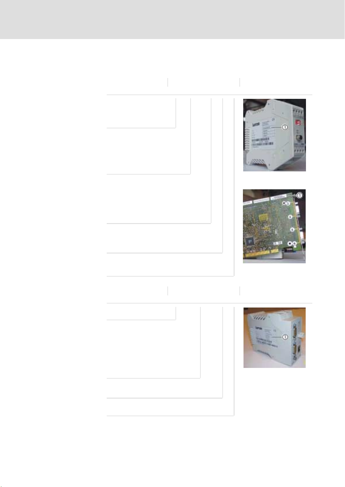
Standard device
ETC xx 0 xx 1A 10
Product
Version
HC = DIN rail, CNC core
PC = PCI plug−in card, CNC core
ETCHC0xx
Number of axes
02 = 2 axes
04 = 4 axes
08 = 8 axes
12 = 12 axes
Hardware version
Modules
Software version ETCPC0xx
ETCH xxxx 1A 10
Product
N003 = power supply unit
T000 = bus termination module
I008 = 8 dig. inputs
I016 = 16 dig. inputs
U008 = 8 dig. outputs
U016 = 16 dig. outputs
A022 = 2 analogue inputs and outputs
each
ETCHxxxx
Hardware version
Software version
EDSTCXN EN 2.0
l
11
Page 12

1
1.3
1.3 Legal regulations
Preface and general information
Legal regulations
Marking
Manufacturer
CE conformity
Application as intended
The components of the ETC Motion Control System are clearly marked by the
contents of the nameplate.
Lenze Drive Systems GmbH, Postfach 101352, D−31763 Hameln
Compliant with EC Directive "Electromagnetic compatibility"
Components of the ETC Motion Control System
ƒ must only be operated under the operating conditions described in the
ETC Hardware Manual.
ƒ are not approved for the use in explosive environments.
ƒ comply with the protection requirements of the EC Directive "Low
voltage".
ƒ are no machines in the sense of the EC Directive "Machines".
ƒ are no household appliances, as components they are intended for
industrial use only.
The downstream user is responsible for ensuring that the EC Directives are
complied with in machine use.
Any other use shall be deemed inappropriate!
Liability
Warranty
The information, data and notes in this manual were up to date at the time
of printing. No claims for the modification of systems and components that
have already been supplied may be made on the basis of the specifications,
illustrations and descriptions in this manual.
No liability is accepted by Lenze as to the suitability of any of the procedures
or circuit recommendations included here.
The information in this manual describe the properties of the products
without guaranteeing them. No liability will be accepted for damage or
disturbance caused by:
ƒ ignoring this manual
ƒ unauthorised alterations to the components of the ETC Motion Control
System
ƒ operating errors and incorrect working on or with the ETC Motion
Control System
See terms of sales and delivery of Lenze Drive Systems GmbH.
Report any claims under warranty to Lenze immediately on discovery of the
defect or fault. The warranty is void in all cases where liability cannot be
established.
12
l
EDSTCXN EN 2.0
Page 13
2 Getting started
This chapter explains the basics of the ETC system and describes the
procedure for realising an automation task.
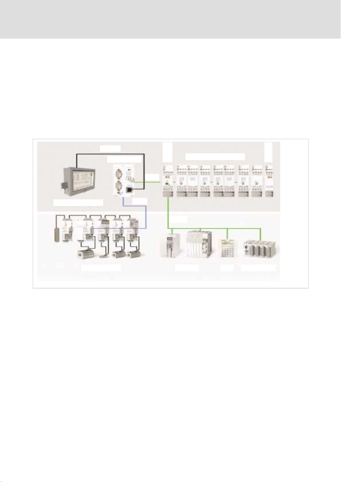
2.1 System overview
2.1.1 Examples for an automation system
Ethernet
ETCHx
CAN1
Getting started
System overview
Examples for an automation system
ETCHN003
ETC-System Components
2
2.1
2.1.1
ETCHT000
ETCHx / ETCPx
IPC with ETCPx
ECS/MCS-System Drives HMI I/O-System IP20
CAN2
CAN-I/O
ETCM001
The core of the automation system is the ETC control in the top hat rail design
(ETCHx) or as PCI insert card (ETCPx).
The top hat rail design ETCHx is normally used in a so−called ETC island
(¶ 15); it communicates via Ethernet with the applications on the IPC (or
standard PC).
The ETCPC is inserted into the IPC (or standard PC) and communicates with
the applications via the PCI bus.
Both designs have two separate CAN busses:
EDSTCXN EN 2.0
ƒ At CAN1 bus (or also ME bus) the I/O modules and any operating
components are connected. Third party devices must comply with teh
DS401 profile of the CANopen specification.
ƒ The drives (e.g. the ECS compact servo) are connected to the connection
for the Motion CAN bus (CAN2) at the front plate. External drives must
comply with the profile DS402 of the CANopen specification and in
particular support the "Interpolated Position Mode".
l
13
Page 14

2
2.1
2.1.1
Getting started
System overview
Examples for an automation system
To carry out its allocated control function the ETC control needs various
programs which are transferred from the IPC (or standard PC):
ƒ Operating system or firmware of the control (e.g. ETCHC.rsc)
ƒ PLC programs (e.g. SPSDummy.prg)
ƒ CNC programs; i.e. cycle and DIN programs (e.g. 9000.zyk or
Nikolaus.din)
IPC
The ETC control is operated and maintained via the IPC (or standard PC). The
following applications might run on it:
ƒ Windows 2000 or XPoperating system
ƒ Terminal program (e.g. HyperTerminal) for establishing the Ethernet
connection between IPC and ETCHx control and for the configuration of
the ETCHx control via the monitor interface (e.g. firmware update). This
is not required for the ETCPx.
ƒ ETC−MMI gateway as communications program between Windows
applications and the ETC control.
ƒ Lenze ETC−MMI for the configuration, operation and monitoring of the
ETC control and for creating CNC programs.
ƒ CoDeSys development environment for the creation and testing of PLC
programs.
) Note!
An external keyboard is required at the IPC for commissioning. It
is not required for normal operation.
14
l
EDSTCXN EN 2.0
Page 15
Getting started
System overview
Layout example for an ETC island
2
2.1
2.1.2
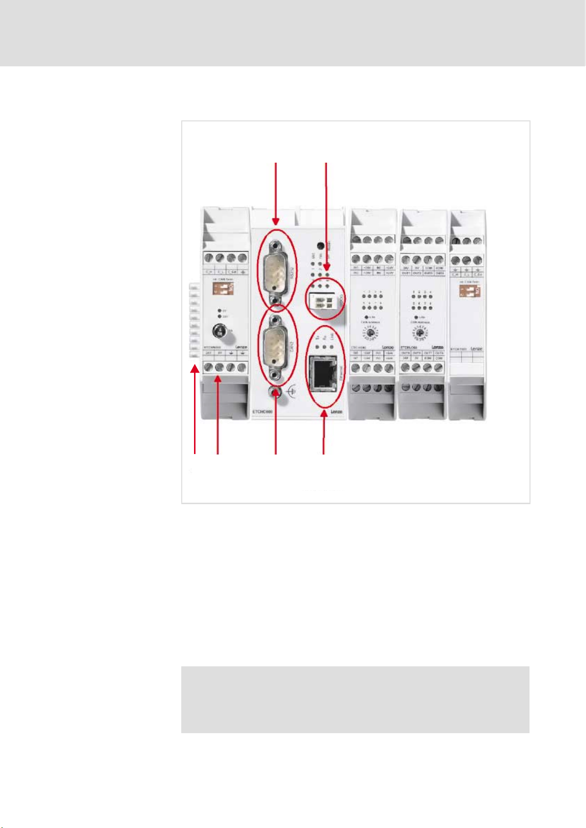
2.1.2 Layout example for an ETC island
ETCHN003
10
ETCHx004
ETCHI016
ETCHI008
ETCHT000
2345
ETCM002
0 Serial interface (RS232)
1 Watchdog (e.g. for emergency stop chain)
2 Ethernet
3 Motion CAN bus (CAN2)
4 24 V supply
5 ME bus (CAN1)
ETCHN003: Power supply unit for the supply of the ETC island and ME bus
connection
ETCHx004: ETC Motion Control for 4 axes (control)
ETCHIxxx: Input module with 16 or 8 digital inputs
ETCHT000: ME bus terminator module
) Note!
To terminate the ME bus DIP switch 1 must be set to ON at both
the power supply unit ETCHN003 and the bus terminator
module ETCHT000.
EDSTCXN EN 2.0
l
15
Page 16

2
2.1
2.1.3
Getting started
System overview
Connecting ETCHx and PC
2.1.3 Connecting ETCHx and PC
Three types of connections are possible between the ETCHx and a PC.
Connection type Cable version Description
Serial connection System cable type EWL 0068
Local connection via Ethernet
(pear−to−pear connection)
Network connection Ethernet patch cable STP Cat5
or a comparable RS232 cable
with double−sided 9−pin
SUB−D socket (for the pin
assignment see ETC Hardware
Manual)
System cable type EWL 0065,
EWL 0066 or EWL 0067
(double−sided RJ45)
(double−sided RJ45)
This connection is only
required for commissioning!
A free COM port at the PC is
connected with the RS232
interface of the ETCHx. The PC
communicates via a terminal
program with the monitor
interface of the ETCHx.
A network card in the PC is
connected with the Ethernet
connection of the ETCHx via a
cross−over cable.
Communication takes place
via the TCP/IP protocol.
The ETCHx is connected to a
separate or existing network
(e.g. Intranet) via an Ethernet
connection. Communication
takes place via the TCP/IP
protocol.
0
0 Connection via serial interface
1 Local TCP/IP connection
2 Network TCP/IP connection
1
2
ETCM004
16
l
EDSTCXN EN 2.0
Page 17
2.2 Status display
Getting started
Status display
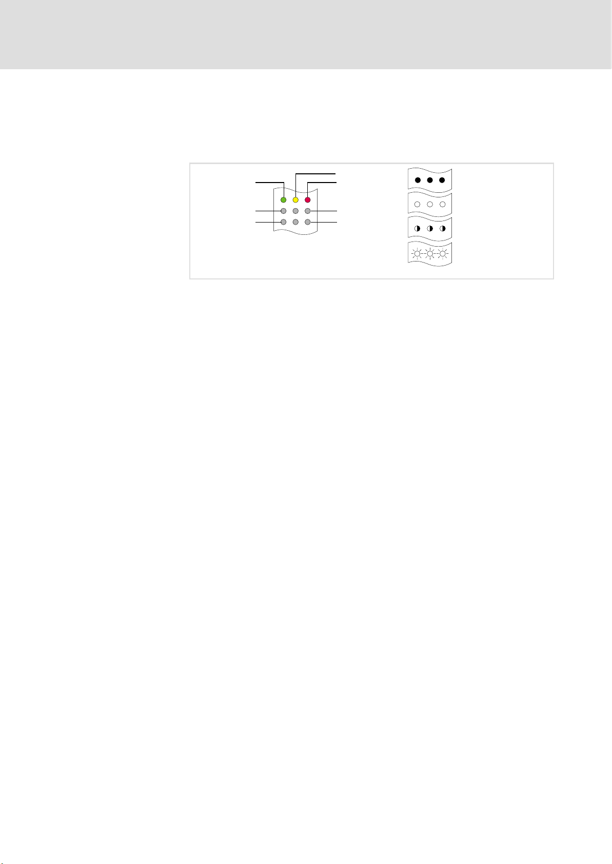
LEDs on the front plate of the ETC report the actual system state. The
meanings of the signals differ in the start−up phase and during operation.
2.2
2
Watchdog (GN)
0 LED on
1 LED off
2 LED any
3 LED flashes
reserved (YE)
Error (RD)
1
4
3
6
0
1
2
3
ETC042
EDSTCXN EN 2.0
l
17
Page 18
2
2.2
Getting started
Status display
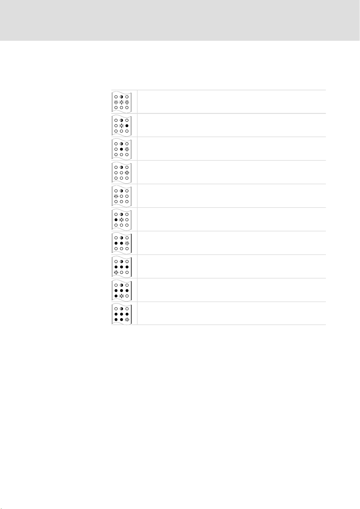
Start−up phase
During start−up a RAM test is carried out. After an error−free RAM test the
LEDs 1 ... 6 produce a running indication. Any errors during the boot sequence
will be signalled by the following pattern of flashing and indications.
Checksum error in the internal FLASH−PROM. 3 times fast consecutive flashing. The
boot loader is then burned afresh into the internal FLASH−PROM. Occurs always
after a boot loader update.
Error in the last 32 kByte of RAM memory (after an update and writing of the boot
loader to the Flash).
Error in the first 32 kByte ofRAM memory.
Error when extracting the boot loader.
Error during the burning of the boot loader into the FLASH−PROM.
Errors in the RAM memory.
Error in the last 32 kByte ofRAM memory.
No firmware loaded or checksum error in the firmware. After 5 times flashing the
boot monitor is activated.
Error when loading the firmware from the FLASH−PROM. After 5 times flashing the
boot monitor is activated.
Error when starting the firmware.
18
l
EDSTCXN EN 2.0
Page 19

Getting started
Status display
2
2.2
Operation
When the control enters the operating mode after start−up, the following
pattern of flashing and indications applies.
LED Meaning
Watchdog Watchdog, must always illuminate when running.
Reserved Without function
ERROR Flashes after an exception (violation of the control program protection during
runtime, exceeding the permitted variable range, division by zero etc.).
LED 1 Flashes at the clock pulse of the coarse interpolator
LED 2 Flashes at the clock pulse of the interpreter
LED 3 Flashes at the clock pulse of the central control
LED 4 Flashes at the clock pulse of the fine interpolator
LED 5 Flashes with each RS232 interrupt or CAN interrupt
LED 6 Flashes at the clock pulse of the PLC cycle time
) Note!
The "flashing" frequency can be so low with short programs,
that the LEDs appear dark.
EDSTCXN EN 2.0
l
19
Page 20

2
2.3
Getting started
Commissioning steps (overview)
2.3 Commissioning steps (overview)
( Stop!
) Note!
Step ETCHC ETCPC Description See
1X− Connect ETCHC via RS232 cable with PC and start ETCHC. ^ 21
2 X − Start terminal program on the PC (if required, configure in
3 X − If the ETCHC is to be operated in the "with MMI"
4 X − Assign the IP address of the ETCHC. ^ 28
5 X X If required, install ETC−MMI and ETC−MMI Gateway. ^ 31
6 − X Install ETCPC in the PC and install the driver. ^ 31
7 X X Start ETC−MMI and ETC−MMI Gateway. ^ 32
8 X X Establish connection between ETC−MMI and ETCxC. ^ 34
9 X X Parameterise drives via machine constants. ^ 36
10 X X Check parameters of the drives. ^ 43
11 X X Test drives in inching mode. ^ 44
12 X X Create CNC program in the ETC−MMI. ^ 47
13 X X Load CNC program into ETCxC, start and test CNC
14 X X If required, install CoDeSys. ^ 51
15 X X Start and configure CoDeSys. ^ 51
16 X X Create PLC program. ^ 60
17 X X Load PLC program into ETCxC, start and test PLC program. ^ 68
18 X X Test CNC and PLC program. ^ 72
Observe the notes in the chapter "Initital switch−on" of the ETC
Hardware Manual before commissioning the system.
Only build in and install the PCI control variant ETCPx in step 6.
^ 21
advance) and activate monitor interface of the ETCHC.
^ 25
operating mode, replace the firmware file on the ETC by
the file "NetBoot.rsc".
^ 49
program.
20
l
EDSTCXN EN 2.0
Page 21

Establishing the communication between PC and ETCHx
2.4 Establishing the communication between PC and ETCHx
) Note!
The steps described in this chapter only apply to the ETCHx
variant (DIN rail variant); they are not required for the ETCPx
variant (PCI card).
2.4.1 Starting ETCHx
1. Connect the serial interfaces of PC and ETCHx.
For this purpose, use the system cable of type EWL 0068 or a comparable
RS232 cable with double−sided 9−pin D−Sub socket (for the pin
assignment see ETC Hardware Manual).
2. Start the PC.
3. Start the ETCHx by mains connection or initialise the ETCHx by a reset
(press the Reset key on the front panel).
As soon as the ETC firmware has been loaded, the green watchdog LED
lights up at the ETCHx .
Getting started
Starting ETCHx
2
2.4
2.4.1
2.4.2 Starting the terminal program "HyperTerminal" and activating the monitor interface
For the communication between PC and ETCHx, you require a terminal
program. The terminal program "HyperTerminal" is available in every
standard Windows installation.
1. If you have already established a connection with an ETC (i.e. if a
connection is already configured), start the connection via <Start>
Programs W Accessories W Communication W HyperTerminal W
ConnectionName.ht. See next section.
If no connection has been configured yet, start the HyperTerminal via
<Start>
The program queries different settings of the telephone connection
because it is also designed for a modem connection. These settings are
not significant in this context.
2. After you have been prompted, enter a name for the connection (for
example "ETC") and click OK.
W Programs W Accessories W Communication W HyperTerminal.
W
EDSTCXN EN 2.0
l
21
Page 22
2
2.4
2.4.2
Getting started
Establishing the communication between PC and ETCHx
Starting the terminal program "HyperTerminal" and activating the monitor interface
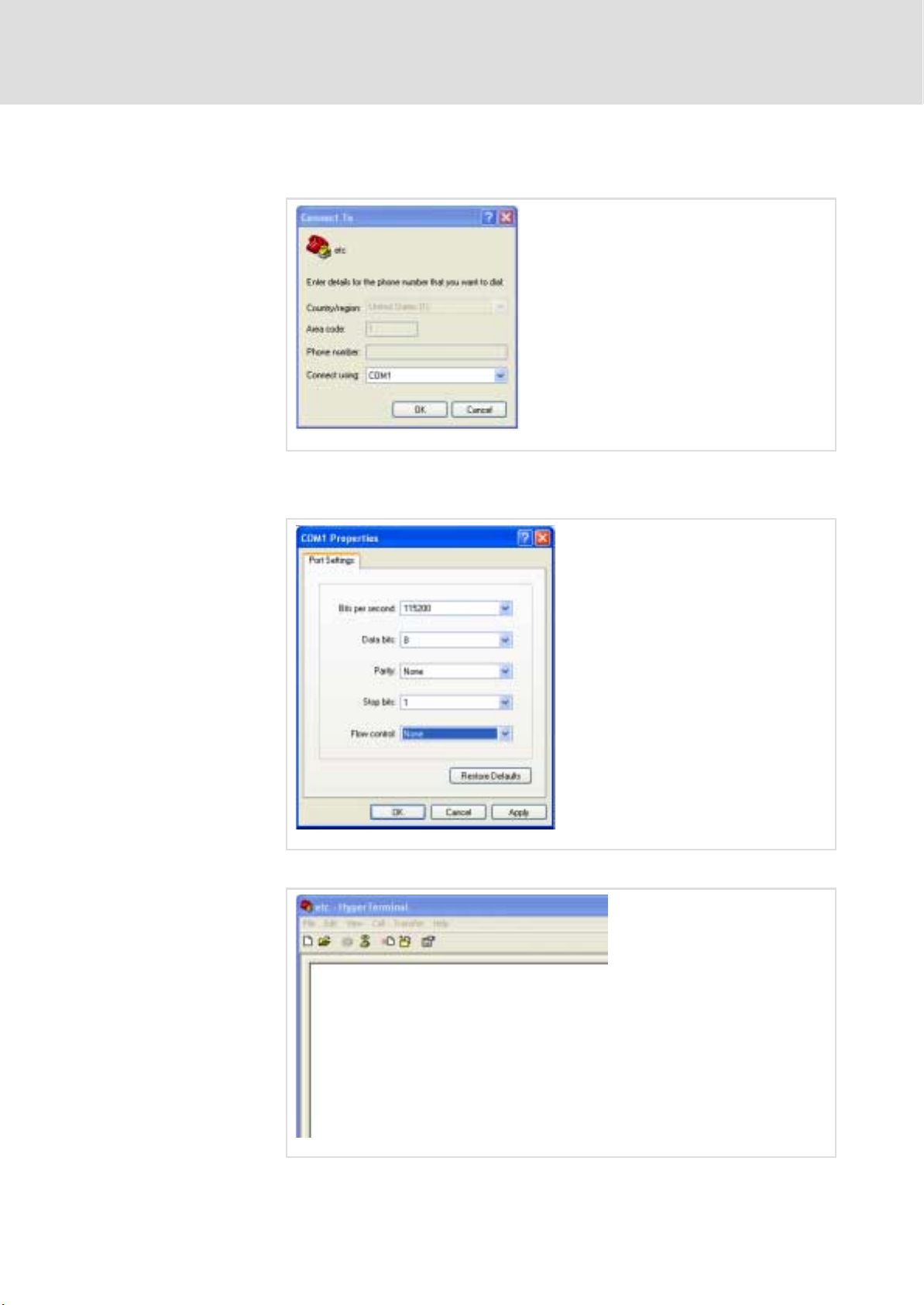
3. In the "Connect to" dialogue, select the PC interface via which you want
to establish the connection (for example "COM1").
ETCM006
4. Click OK.
5. In the "COMx Properties " dialogue, enter the following data:
ETCM007
6. Click OK.
22
l
ETCM008
EDSTCXN EN 2.0
Page 23
Getting started
Establishing the communication between PC and ETCHx
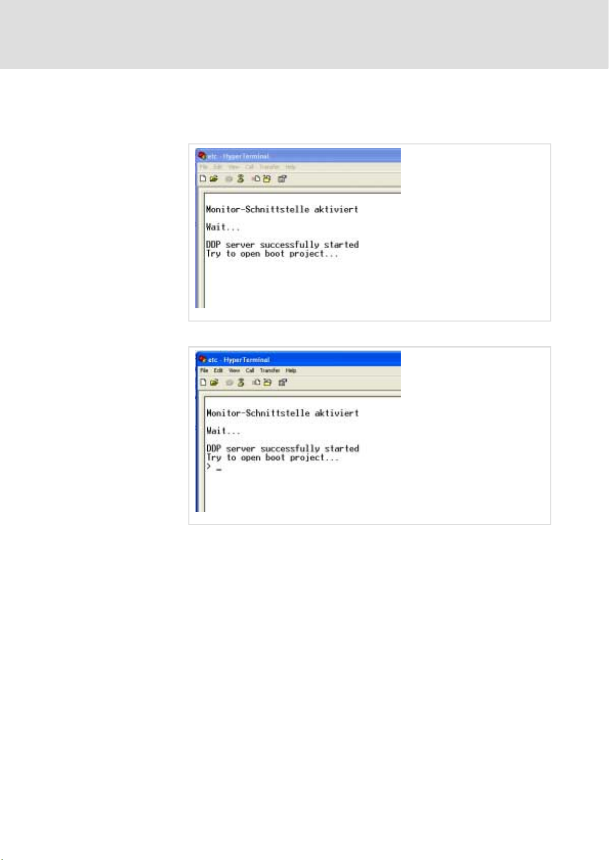
Starting the terminal program "HyperTerminal" and activating the monitor interface
As soon as a connection has been established between the PC and ETC, the
LEDs 1 ... 6 at the ETCHx start to flash circulatingly. The message "Wait Boot
Loader" appears and the following window is displayed:
2
2.4
2.4.2
ETCM009
7. Press the <?> key until the prompt ">" appears.
The monitor interface has been started. You can now send commands to
the ETC via the keyboard.
ETCM010
EDSTCXN EN 2.0
l
23
Page 24

2
2.4
2.4.2
Getting started
Establishing the communication between PC and ETCHx
Starting the terminal program "HyperTerminal" and activating the monitor interface
Important commands of the
monitor program
Fault elimination
Command Meaning
dir [dr:][pattern] Shows the contents of the specified drive. The flashdisk (sd:) is preset, other
possible drives are program storage (ps:), Ram disk (rd:) and floppy disk
(fd:), if existing. As pattern, the usual MS−DOS patterns can be used, e.g.:
*.din
del [dr:][pattern] Deletes the specified files on the specified drive. The flash disk (sd:) is
preset.
cd [dr:] Changes to or shows the currently selected drive. The flash disk (sd:) is
preset.
format dr: Formats the current disk and thus deletes all files on this disk. A disk name
must be specified.
reboot Resets the control system. To activate the boot monitor, the "!" key must be
pressed afterwards until the boot monitor responds (this may take
3−4 seconds).
help Displays the help page with commands of the monitor program.
ver Displays version string
ipconf Configures network parameters for Ethernet interface
hwconf Displays hardware configuration of the control system (CPU type, memory
etc.)
If you cannot establish a connection to the ETCHx by means of the described
procedure, proceed as follows:
1. Check the cabling between PC and ETCHx.
2. Check the connection parameters of the terminal program.
A first test of the cable connection can be performed by means of a bridge
between the pins 2 and 3 at the socket of the cable (control system side):
ƒ Afterwards, the terminal program is called as usual and any letters can
be entered via the keyboard.
ƒ If the entered characters of the keyboard are correctly displayed in the
mask of the terminal program (the characters are sent back by the
bridge as echo), the cable must be checked for exchanged pins (pin2/3),
for short circuit and the connection must be checked for correct
parameter setting.
24
l
EDSTCXN EN 2.0
Page 25

Getting started
Establishing the communication between PC and ETCHx
Setting the operating mode of the ETCHx
2
2.4
2.4.3
2.4.3 Setting the operating mode of the ETCHx
The ETCHx can be operated in two operating modes:
ƒ Variant "Standalone" (delivery variant)
– Directly after the voltage has been applied, the control system loads
the firmware.
– The control system executes a fixed program.
ƒ Variant "with MMI"
– After the voltage has been applied, the control system waits until the
firmware is loaded by a PC via any MMI program (e.g. ETC−MMI).
– Variable user programs can be executed.
Comparison of the operating
modes
Use The control system operates a
User program A fixed program runs in the
Installed firmware on the
control system
Installation of the firmware The firmware is loaded and
Behaviour of the control
system after the voltage has
been applied
LED display after the voltage
has been applied
Starting the firmware Before the start, the firmware
Standalone (delivery) With MMI
machine without further
coupling to a PC.
control system.
Boot loader
firmware
installed in the EEPROM by the
boot loader.
After the voltage has been
applied, the control system
automatically starts with its
firmware.
After the firmware has been
started successfully, the green
watchdog LED lights up.
is loaded from the EEPROM of
the control system into the
RAM and started.
The control system operates a
machine with coupling to a
user interface, which is used
for loading programs and
operating the control system.
Variable user programs can be
loaded into the control
system.
Boot loader
loader
The Loader is loaded and
installed in the EEPROM by the
boot loader.
After the voltage has been
applied, the control system
waits until the firmware is
loaded via the PC.
The successful start of the
loader is indicated by
circulating LEDs (1 ... 6).
The firmware is located on the
PC and is loaded into the RAM
of the control system and
started when the MMI user
interface is started.
After the firmware has been
started successfully, the green
watchdog LED lights up.
Set the "Standalone"
operating mode
EDSTCXN EN 2.0
The "Standalone" operating mode is factory−set.
) Note!
If the ETCHx has already been operated in the "with MMI"
operating mode and is to be reset to the "Standalone" operating
mode, the file "NetBoot.rsc" (loader) must be deleted in the
control system and the firmware file ETCHC_A.rsc (ETCHC) or
ETCPC.rsc (ETCPC) is to be transferred instead. For this purpose,
proceed as described in the following section; the files that are
to be exchanged are the only difference.
l
25
Page 26
2
2.4
2.4.3
Getting started
Establishing the communication between PC and ETCHx
Setting the operating mode of the ETCHx
Set the "With MMI" operating
mode
For the "With MMI" operating mode, the firmware file must be replaced by
the file "NetBoot.rsc" (Loader) on the ETCHx.
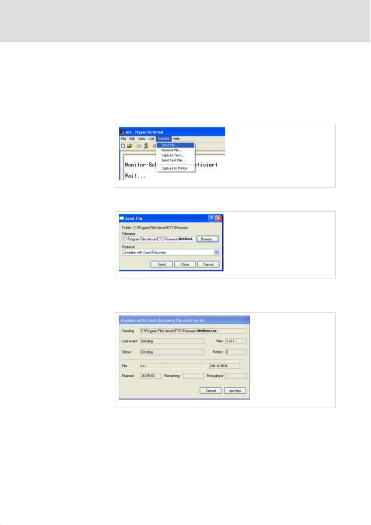
1. To delete the firmware, enter the following in the HyperTerminal: del
sd: etc*.rsc. Afterwards, press the <Enter> key.
2. To transfer the Loader to the ETC, activate the menu item Transfer
W
Send File in the HyperTerminal.
ETCM021
3. Specify the path to the file "NetBoot.rsc" and select the protocol
"Zmodem with Crach Recovery".
ETCM022
4. Click on Send.
While the file is being loaded into the control system, the following figure
is displayed. On the ETC front plate, the LEDs 1 ... 6 flash circulatingly.
ETCM023
26
l
EDSTCXN EN 2.0
Page 27
Getting started
Establishing the communication between PC and ETCHx
Setting the operating mode of the ETCHx
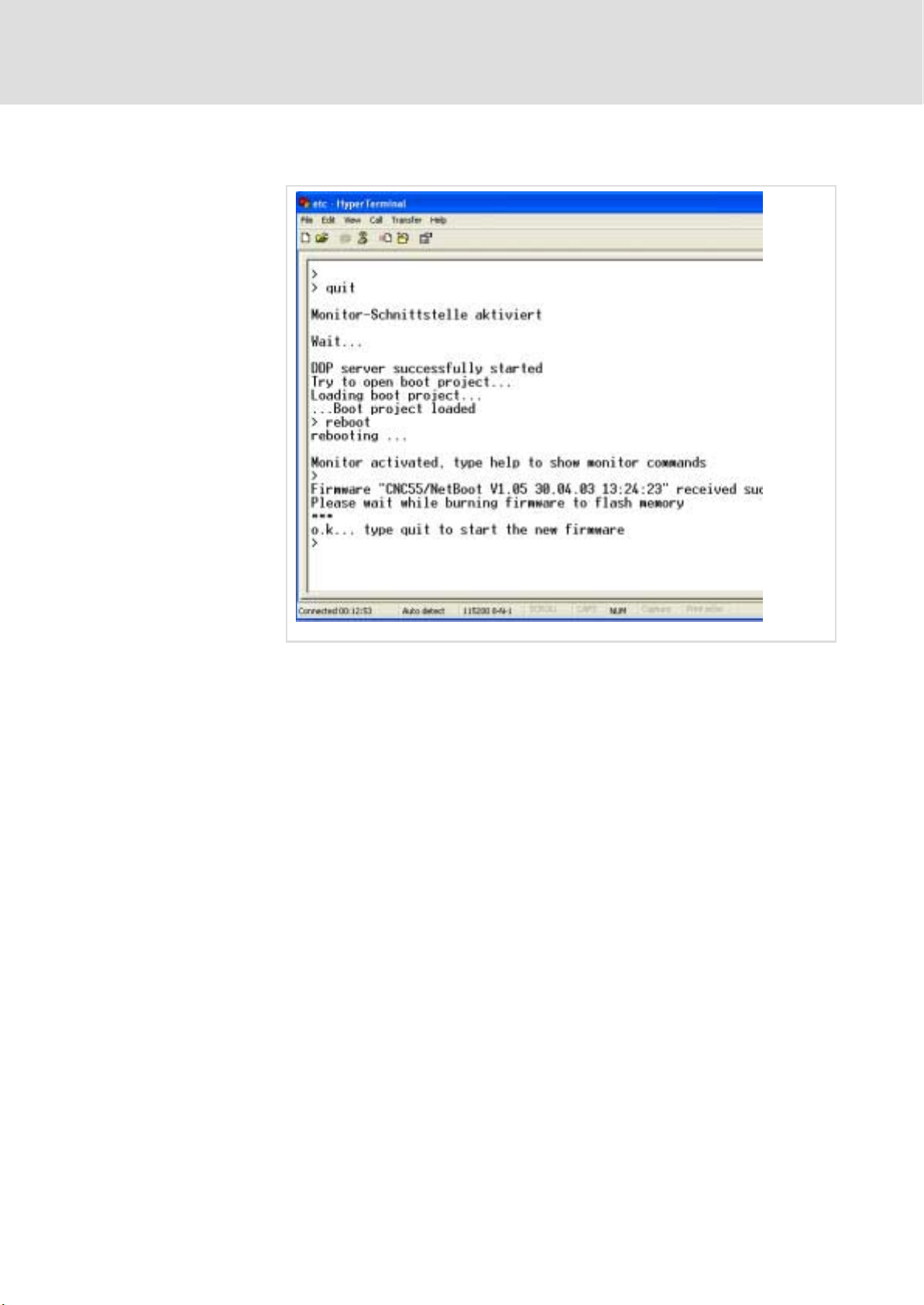
After loading is complete, the following figure is displayed:
2
2.4
2.4.3
The control system waits until the firmware is loaded from the PC; on the
ETC front plate, the LEDs 1 ... 6 flash circulatingly.
5. In the HyperTerminal window, enter quit and confirm the command
with <Enter> .
The firmware starts. On the ETC front plate, the green watchdog LED
lights up.
ETCN007
EDSTCXN EN 2.0
l
27
Page 28

2
2.4
2.4.4
Getting started
Establishing the communication between PC and ETCHx
Assigning the IP address of the ETCHx
2.4.4 Assigning the IP address of the ETCHx
For communication via a network or a local Ethernet cable, the ETCHx
requires a unambiguous IP address (with subnet mask) that matches the
other nodes. When the control system is delivered, it has a specific, but
random IP address.
The IP address of the ETCHx is assigned via the monitor interface (as
described in the following). This IP address is requested when connections
are established in the ETC−MMI Gateway (¶ 34).
Specify the IP address according to the following general rules for IP
addresses:
Separate (local) network
segment
If the control system and PC are connected with a local network segment or
via a direct Ethernet connection (without Internet/Intranet connection),
assign IP addresses of class B or class C to the two network stations.
ƒ Addresses of class B are in the range from 128.0.0.0 to
191.255.255.255. The corresponding subnet mask is 255.255.0.0
(default).
ƒ Addresses of class C are in the range from 192.0.0.0 to
223.255.255.255. The corresponding subnet mask is 255.255.255.0
(default).
Existing network segment
The gateway address is not relevant here. You can enter a free IP address of
the subnetwork (not 0.0.0.0).
Example IP address Subnet
This address must be assigned to the ETCHC and
specified as connection parameter in the ETC−MMI
Gateway ^ 34:
This address must be specified in the network
connection of the PC (TCP/IP settings):
181.16.1.10
181.16.1.11 255.255.0.0 181.16.1.1
mask
255.255.0.0 181.16.1.1
Gateway
address
) Note!
Do not use any leading zeros in the IP addresses. Otherwise, the
IP address will be interpreted as octa decimal number.
If ETCHx and PC are to be connected with an existing network segment, the
addresses and the subnet mask must be assigned by the network
administrator.
) Note!
If the Ethernet adapter supports 100Base−T technology, "Auto
Select" or "10Base−T" must be set for the "Media Type" property.
28
l
EDSTCXN EN 2.0
Page 29
Getting started
Establishing the communication between PC and ETCHx
Assigning the IP address of the ETCHx
2
2.4
2.4.4
MAC address
Assigning an IP address
Like any other device with Ethernet controller, the ETCHx receives an
unchangeable and worldwide unique physical Ethernet address, also called
MAC ID (Media Access Control Identity), from the manufacturer. It can be
used for addressing on the hardware level. The address has a fixed length of
6 bytes (48 bits) and contains an address type, an identification of the
manufacturer and a serial number.
MAC−ID of the ETC: 00:05:7e:xx:xx:xx (with xx:xx:xx = serial number).
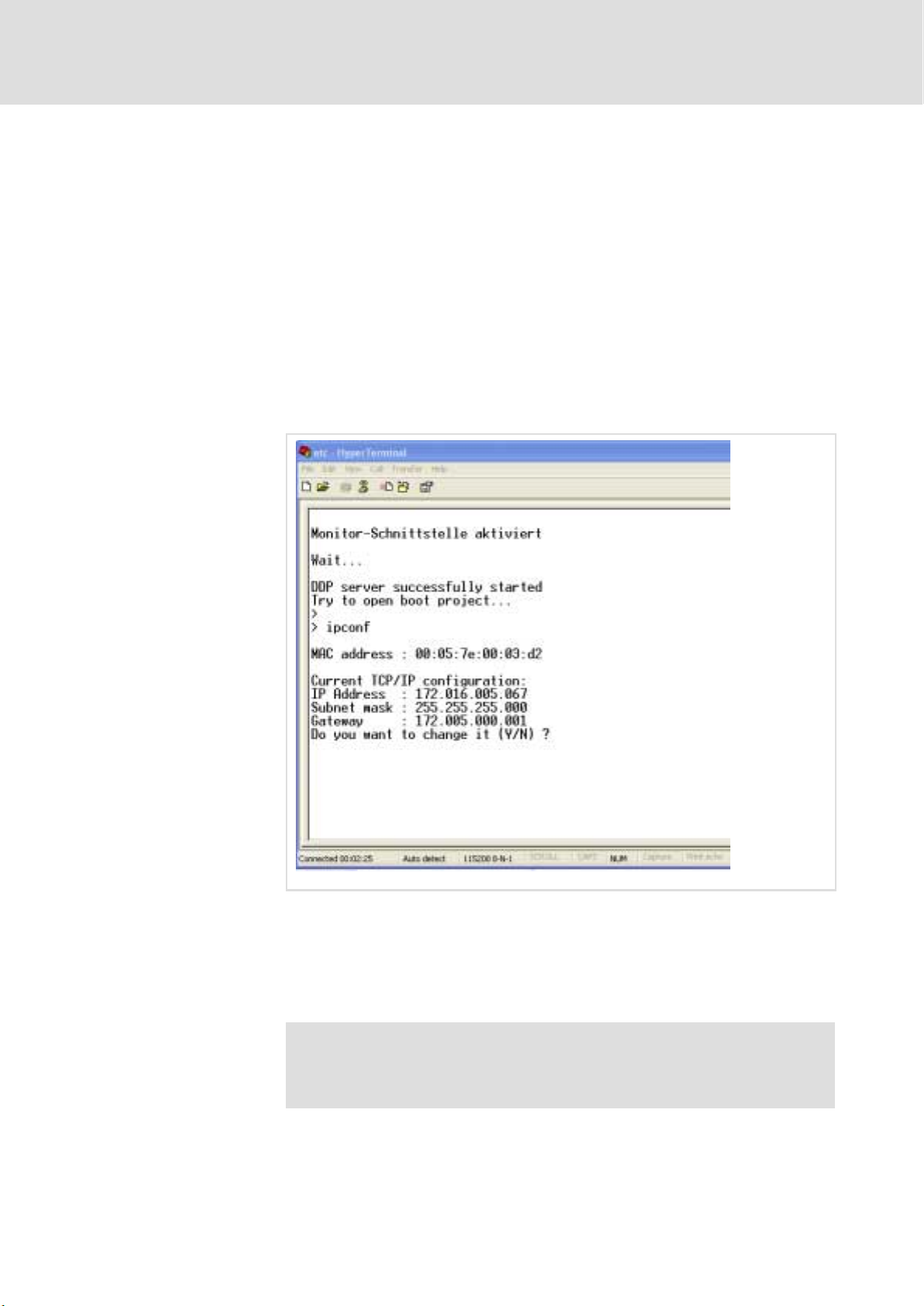
The IP address of the ETCHx is specified via the monitor interface.
1. In the HyperTerminal, enter the command ipconf and confirm the
command with <Enter>.
The MAC−ID and the current address setting of the ETCHx are displayed.
ETCM011
2. Press the <Y> key and change the settings. Follow the instructions of
the monitor interface.
Select an IP address according to the rules specified at the beginning of
the section.
The HyperTerminal program can now be quit.
) Note!
Note down the IP address because it must be specified when
creating connections in the ETC−MMI Gateway (¶ 34).
EDSTCXN EN 2.0
l
29
Page 30

2
2.5
2.5 Configuring ETC−MMI and ETC−MMI gateway
Getting started
Configuring ETC−MMI and ETC−MMI gateway
The program "ETC−MMI" is used for the following tasks:
ƒ Configuring the control system
ƒ Operating and monitoring the control system
ƒ Maintenance of the control system and error diagnosis
The MMI gateway is the communications program between Windows
applications and ETC control systems. Different applications such as MMIs,
configuration tools or OPC servers can establish connections to one or more
control systems at the same time.
The gateway implements all required mechanisms for access control, error
handling and diagnostics and supports control−specific hardware drivers
and communication protocols. By means of the configuration tools, new
connections can be added and existing connections can be edited.
The ETC−MMI Gateway is installed during the installation of the Lenze
ETC−MMIs. It can also be installed as a separate application. In this case, it is
available as communication channel for other applications.
, For further information, please refer to the chapters "ETC−MMI
Gateway" (¶ 276) and "ETC−MMI" (¶ 286).
30
l
EDSTCXN EN 2.0
Page 31

2.6 Installing ETC−MMI
( Stop!
) Note!
1. In Windows File Explorer, open the program "setup.exe" on the
2. Follow the instructions of the installation program. The following will
Getting started
Installing ETC−MMI
Building in and installing the ETCPx
Only install the PCI control variant ETCPx after installing the
ETC−MMI and before starting the ETC−MMIs.
The ETC−MMI Gateway is installed during the installation of the
Lenze ETC−MMIs
ETC−MMI installation CD.
be requested:
– Demo or standard installation
– Control type (ETCHC or ETCPC)
– IP address of the ETCHC (¶ 28) or index of the ETCPC (indexes of the
PCI cards are in the range 0 ... 9 and are automatically assigned by the
driver. The first ETCPx has the index 0).
In the start bar, the entry "Lenze ETC−MMI" is created. It can be used to
start the application.
2.6
2.6.1
2
3. For an ETCHC: Check that the TCP/IP protocols are installed in the
network properties (Start
For an ETCPC: Install the ETCPC plug−in card in the PC. Observe the notes
in the ETC Hardware Manual.
2.6.1 Building in and installing the ETCPx
1. If you use an ETCPx plug−in card as control system, install it in the PC
now. Please observe the notes in the ETC Hardware Manual.
2. Start the PC and open the BIOS settings.
For Phoenix BIOS: set Advanced\Plug & Play O/S to [NO].
For other BIOS, check the corresponding entry, e.g. PNP OS on [NO].
After the start of the operating system, the hardware wizard detects the
new hardware and queries the driver.
3. Install the ETCPx driver from the ETC−MMI CD (...\wdm2000\ETCPC.inf)
4. Restart the PC.
W Settings W Control Panel W Network).
EDSTCXN EN 2.0
l
31
Page 32

2
2.7
2.7 Starting ETC−MMI
Getting started
Starting ETC−MMI
1. Start the ETC−MMI via <Start>
The ETC−MMI Gateway is automatically started. The application can be
seen on the task bar:
W Programs W Lenze W ETC
ETCN011
ETCN001
) Note!
It can be defined which operating mode is displayed when the
user interface is started. (¶ 327).
For a detailed description of the MMIs, refer to chapter
"ETC−MMI" (¶ 286).
For a detailed description of the MMI gateways, refer to chapter
"ETC−MMI Gateway" (¶ 276).
32
l
EDSTCXN EN 2.0
Page 33

Switching the language in the ETC−MMI
2.7.1 Switching the language in the ETC−MMI
1. In the ETC MMI window, press <F12> (diagnostics).
The MMI window opens in the "Diagnostics" operating mode.
2. In the ETC−MMI diagnostics window, press <F8> (MMI−config.).
The window "delphmmi.ini" opens (¶ 283).
Getting started
Starting ETC−MMI
2
2.7
2.7.1
3. Specify the language in the line Language:
German: "Lenze"
English: "Lenze_gb"
4. Close the window with <Enter>.
5. Quit and restart the ETC−MMI.
EETCN095
EDSTCXN EN 2.0
l
33
Page 34

2
2.7
2.7.2
Getting started
Starting ETC−MMI
Establishing a connection between ETC−MMI and ETC
2.7.2 Establishing a connection between ETC−MMI and ETC
1. On the task bar, click on the ETC−MMI Gateway icon.
A menu opens.
Settings: Start configuration interface.
About: Display version and manufacturer information.
Exit: Close gateway (if there are active connections to an application, a
warning is displayed).
ETCN001
ETCN002
2. Click on Settings.
ETCN003
Connections: List of the already configured connections. A green LED next
to the connection name indicates an active connection, via which the
messages and/or cyclic data are transferred. Via the Settings button, you
can edit the communication parameters of the selected connection
(¶ 278).
Trace: In the case of faults in the communication, you can activate trace
logs on this tab (¶ 281).
About: Display version and manufacturer information.
34
l
EDSTCXN EN 2.0
Page 35

Getting started
Starting ETC−MMI
Establishing a connection between ETC−MMI and ETC
3. To create a new connection, click on Add on the "Connection" tab.
4. Specify a name for the connection.
To enable an application to communicate with a control system via the
ETC−MMI Gateway, each connection must be assigned an unambiguous
name. You can choose any name. Assign e.g. consistent names "ETC0",
"ETC1" ... or application−specific names "ramp", "laser control" etc. A
name can contain up to 31 ASCII characters ("A ... Z", "a ... z" , "0 ... 9").
2
2.7
2.7.2
ETCN004
5. Select a connection type:
ƒ UDP connection for ETCHx control systems
Ethernet communication via DPR/UDP/IP protocol.
ƒ PCI connection for ETCPx control systems
DPR communication via a WDM driver (ETCPC.sys, in the scope of supply
of the ETCPC).
6. Enter a communication parameter in the "IP address" field:
ƒ ETCHC = IP address (¶ 28)
ƒ ETCPC = Index of the PCI cards (indexes of the PCI cards are in the range
0 ... 9 and are automatically assigned by the driver. The first ETCPx has
the index 0).
7. Close the dialogue via OK.
Your entries are saved in the file "mmigtway.ini" (¶ 283). If a connection
with the same parameters already exists, the error "Gateway cannot
change the parameter" is reported.
EDSTCXN EN 2.0
l
35
Page 36

2
2.8
2.8.1
Getting started
Parameterising drives via machine constants
Overview of the most important machine constants
2.8 Parameterising drives via machine constants
The properties of the drives must be parameterised both in the drive itself
and in the control system.
In the control system, the properties are assigned via machine constants
(MCs). A machine constant consists of a keyword and the corresponding
values; for example "MK_VMAX 20".
The machine constants are saved on the PC in a text file with the extension
.mk (e.g. ETCHC.mk for the ETCHC) and are loaded into the control system via
the ETC−MMI. The machine constants can be changed after loading via a
dialogue in the ETC−MMI.
2.8.1 Overview of the most important machine constants
The machine constants listed in the following are mandatory for the
operation of the drive. In relation to the drives, they are only a subset of the
required parameterisation. For a detailed description of all machine
constants, refer to chapter "Machine constants" (¶ 190).
Test setting
( Stop!
The control system only initialises the drives via its machine
constants and determines path−related parameters. The
control−related parameters, the safety functions of the drives
and the parameters of the reference run must be parameterised
in the drive itself by means of the GDC (Global Drive Control).
MC keyword No. of
values
MK_TEST_OHNEMECHANIK 1 0, 1 0: "Achsrechner" ("Axis computer") of
MK_SPS_DUMMY 1 0, 1, −1 0: with integrated PLC function
Values Meaning
the NC firmware works and considers
the actual position counter of the
drive.
1: "Achsrechner" ("Axis computer") of
the NC firmware works, but simulates
the actual position counter of the drive
(actual position = desired position for
the test of the NC function without
mechanics).
1: without integrated PLC function
−1: without integrated PLC function,
releases are reset
36
l
EDSTCXN EN 2.0
Page 37

Getting started
Parameterising drives via machine constants
Overview of the most important machine constants
2
2.8
2.8.1
Hardware configuration
MC keyword No. of
values
MK_CANDRIVES 12 −1, 0 ... 11 Assignment of the axis number 0 ... 11 to
MK_APPLACHSIDX 18 −1, 0 ... 11 Assignment of the axis number 0 ... 11 to
MK_ACHSENART 12
Values Meaning
the CAN node address in the order of the
CAN node address 1 ... 12
−1: No axis number is assigned to the
node address
0 ... 11: An axis number is assigned to the
node address
the axis description in the order of the
axis description X ,Y, Z, C, U, V, W, A, B, u,
v, w, x, y, z, a, b, c
−1: No axis number is assigned to the axis
description
0 ... 11: An axis number is assigned to the
axis description
Assignment of the axis type to the axis
number in the order of the axis number 0
... 11
Bit 0 Axis type
xxxxxxx0 Linear axis
xxxxxxx1
xxxxxx0x Observe HW limit switch
xxxxxx1x
xxxx00xx Normal axis
xxxx01xx
xxxx10xx Measurement axis
xxxx11xx
xx00xxxx Rotation axis with absolute
xx01xxxx
xx11xxxx Modulo 360° axis − shortest distance
x0xxxxxx Normal axis
x1xxxxxx
0xxxxxxx Normal axis
1xxxxxxx
Rotation axis
Bit 1 Limit switch
Ignore HW limit switch
Bit 3/2 Axis type
Spindle
Spindle and measurement axis
Bit 5/4 Only for xxxxxxx1,
rotation axis
positioning
Modulo 360° axis − sign indicates the
direction
is travelled (ETCHC only)
Bit 6 Gantry axis
Gantry axis (synchronous axis with
mechanical coupling)
Bit 7 Handwheel
Handwheel
Software configuration
EDSTCXN EN 2.0
MC keyword No. of
values
MK_CANOPEN_BAUDRATE 2 0,
MK_DELTAT 1 Rough interpolation cycle in [ms]
Values Meaning
1st parameter for CAN1
10... 1000
2nd parameter for CAN1
0: no device connected
>0: baud rate for CAN−Open in kB
l
37
Page 38

2
2.8
2.8.1
Getting started
Parameterising drives via machine constants
Overview of the most important machine constants
Setting of the axes
Axis−related limit values
Path−related limit values
MC keyword No. of
values
MK_IMPULSE 12 Number of impulses per [MK_WEG]
MK_WEG 12 Distance in [mm] or [degree] which
MC keyword No. of
values
MK_MODVMAX 12 Modal axis speed (manual traversing)
MK_VMAX 12 Max. axis speed [m/min] or [U/min] in
MK_BESCHL 12 Acceleration ramp [m/s2] or [U/s2] in
MK_BREMS 12 Deceleration ramp [m/sec2] or [U/s2] in
MK_T_BESCHL 12 Damping time constant for acceleration
MC keyword No. of
values
MK_VBAHNMAX 1 Max. material speed [m/min]
MK_BAHNBESCHL 1 Acceleration ramp [m/s2]
MK_BAHNBREMS 1 Deceleration ramp [m/s2]
MK_T_BAHNBESCHL 1 Dampening time constant for
Values Meaning
(after the quadruplication!) in the order
of the axis number 0 ... 11
corresponds to the value of
[MK_IMPULSE] in the axis computer in
the order of the axis number 0 ... 11
Values Meaning
[m/min] or [U/min] in the order of the
axis number 0 ... 11
the order of the axis number 0 ... 11
order of the axis number 0 ... 11
the order of the axis number 0 ... 11
and deceleration ramps [ms] in the order
of the axis number 0 ... 11
Values Meaning
deceleration and acceleration ramps [ms]
38
l
EDSTCXN EN 2.0
Page 39

2.8.2 Machine constant file ETCxC.mk
In the control variant "With MMI", the file ETCxC.mk is loaded into the
control system ETCxC when the ETC−MMI is started. In the "Standalone"
variant, it is detected that the machine constants have already been loaded.
The following example of machine constants is an excerpt from the file
ETCxC.mk with preset machine constants, which must be adapted for the
specific application.
Getting started
Parameterising drives via machine constants
Machine constant file ETCxC.mk
2
2.8
2.8.2
Test setting
Hardware configuration
Software configuration
Setting of the axes
Axis−related limit values
MC keyword No. of
values
MK_TEST_OHNEMECHANIK 1 0
MK_SPS_DUMMY 1 0
MC keyword No. of
values
MK_CANDRIVES 12 0, 1, 2, 3, −1, −1, −1, −1, −1, −1, −1, −1
MK_APPLACHSIDX 18 0, 1, 2, 3, 4, 5, 6, 7, 8, 9, 10, 11, 13, 14, 15, 16, 17
MK_ACHSENART 12 0, 0, 0, 0, 0, 0, 0, 0, 0, 0, 0, 0
MC keyword No. of
values
MK_CANOPEN_BAUDRATE 2 500, 1000
MK_DELTAT 1 2
MC keyword No. of
values
MK_IMPULSE 12 65536, 65536, 65536, 65536, 65536, 65536,
MK_WEG 12 10, 10, 10, 10, 10, 10, 10, 10, 10, 10, 10, 10
MC keyword No. of
values
MK_MODVMAX 12 10, 10, 10, 10, 10, 10, 10, 10, 10, 10, 10, 10
MK_VMAX 12 20, 20, 20, 20, 20, 20, 20, 20, 20, 20, 20, 20
MK_BESCHL 12 2, 2, 2, 2, 2, 2, 2, 2, 2, 2, 2, 2
MK_BREMS 12 2, 2, 2, 2, 2, 2, 2, 2, 2, 2, 2, 2
MK_T_BESCHL 12 0, 0, 0, 0, 0, 0, 0, 0, 0, 0, 0, 0
Values
Values
Values
Values
65536, 65536, 65536, 65536, 65536, 65536
Values
Path−related limit values
EDSTCXN EN 2.0
MC keyword No. of
values
MK_VBAHNMAX 1 20
MK_BAHNBESCHL 1 2
MK_BAHNBREMS 1 2
MK_T_BAHNBESCHL 1 0
Values
l
39
Page 40

2
2.8
2.8.3
2.8.3 Notes on loading the MK file into the control system
Getting started
Parameterising drives via machine constants
Notes on loading the MK file into the control system
Make sure that the number of parameters in the file of machine constants
corresponds to the number of axes (12) in the operating system of the
control system.
When the machine constant file is loaded into the control system, 3 cases are
possible:
ƒ The number of parameters in the file equals the maximum number in
the operating system.
The parameters overwrite the saved machine constants in the control
system.
ƒ The number of parameters in the file is greater than the maximum
number in the operating system.
The parameters overwrite the saved machine constants in the control
system up to the maximum number. An error message is generated for
each parameter of the file that is not adopted.
ƒ The number of parameters in the file is smaller than the maximum
number in the operating system.
The parameters overwrite the saved machine constants in the control
systems. The missing machine constants up to the maximum number are
completed by the entries that already exist in the control system.
) Note!
If the control system is in an error status (display in the ETC−MMI
in the SETUP operating mode: "NCR: ERROR"), the loaded
machine constants are not adopted in the control system.
The machine constants have only been adopted correctly when
the control state "Idle" (display in the ETC−MMI in the SETUP
operating mode: "NCR: STEHT" ("NCR: STANDS")) is reached.
40
l
EDSTCXN EN 2.0
Page 41

Parameterising drives via machine constants
Example for adapting a machine constant file
2.8.4 Example for adapting a machine constant file
The drive configuration has 3 drives with the following properties:
Axis number 0 1 1
CAN node address 8 7 3
CAN baud rate 500 kB
Axis description c X (X’)
Axis type Rotation axis Linear axis with
Resolution pulses 65536 65536 like drive 2
The machine constant file must look as follows:
Getting started
Drive 1 Drive 2 Drive 3
handwheel
Gantry axis for
drive 2 with the
same properties
2
2.8
2.8.4
Test setting
Hardware configuration
Software configuration
Setting of the axes
Explanation
MC keyword No. of
values
MK_TEST_OHNEMECHANIK 1 0
MK_SPS_DUMMY 1 0
MC keyword No.of
values
MK_CANDRIVES 12 −1, −1, 1, −1, −1, −1, 1, 0, −1, −1, −1, −1
MK_APPLACHSIDX 18 1, −1, −1, 0, −1, −1, −1, −1, −1, −1, −1, −1, −1, −1, −1, −1, −1,
MK_ACHSENART 12 1, 192, 0, 0, 0, 0, 0, 0, 0, 0, 0, 0
MC keyword No. of
values
MK_CANOPEN_BAUDRATE 2 500, 1000
MC keyword No. of
values
MK_IMPULSE 12 65536, 65536, 65536, 65536, 65536, 65536,
Values
Values
−1
Values
Values
65536, 65536, 65536, 65536, 65536, 65536
To define a synchronous axes, the same axis number is entered at 2 CAN note
addresses in MK_CANDRIVES. This creates a forced coupling of the axes of
the two CAN node addresses. The CAN axis with the lower node address
automatically is the master axis, the axis with the higher node address and
the same axis number is the slave axis (synchronous axis).
EDSTCXN EN 2.0
The gantry axis (X’, in MK_ACHSENART) is a special case of the synchronous
axes. It is a mechanical forced coupling of 2 axes. Thus, the gantry axis is not
entered as an axis of its own in MK_CANDRIVES, but as a reference to the X
axis.
l
41
Page 42

2
2.8
2.8.5
2.8.5 Adapting machine constants in the ETC−MMI
Getting started
Parameterising drives via machine constants
Adapting machine constants in the ETC−MMI
1. In the ETC MMI window, press <F12> (diagnostics).
The MMI window opens in the "Diagnostics" operating mode.
2. Press <F6> (machine const.).
3. Press F6 (Change current MCs) again.
The current machine constants are loaded.
01
4
0: Available machine constants
1: Date and version of the NC firmware
2: Value of the selected machine constant
3: Accept changed value
4: Short description of the selected machine constant
2
3
EETCN095
42
4. In the field of the available machine constants 0, select the machine
constant that you want to adapt.
5. To change the value of the selected machine constant, press the
<Space bar> and enter the new value in the field 2.
6. To accept the value, press the key 3.
7. After you have made all changes, press <Enter>.
The changes are transferred to the ETC and updated in the MK file.
l
EDSTCXN EN 2.0
Page 43

Test setting
Getting started
Parameterising drives via machine constants
Checking the parameters of the drives
2.8
2.8.6
) Note!
Basically, the operation of the CNC program is also possible:
ƒ without connected mechanics and drives.
This is achieved by setting the machine constant
MK_TEST_OHNEMECHANIK=1.
ƒ without a PLC program.
This is achieved by setting the machine constant
MK_SPS_DUMMY=1.
For the following tests with mechanics, the above−mentioned machine
constants must be set as follows:
2
MC keyword No. of
MK_TEST_OHNEMECHANIK 1 0
MK_SPS_DUMMY 1 1
2.8.6 Checking the parameters of the drives
After the machine constants have been adapted, the connected drives can
be checked via their tolerance margin in the diagnostics.
1. In the ETC MMI window, press <F12> (diagnostics).
The MMI window opens in the "Diagnostics" operating mode.
values
Values
EDSTCXN EN 2.0
ETCN012
Correctly parameterised drives show an alternating tolerance margin
around the zero point.
l
43
Page 44

2
2.8
2.8.7
2.8.7 Testing the drives in inching mode
Getting started
Parameterising drives via machine constants
Testing the drives in inching mode
After the machine constants have been adapted, the drives must be tested
in inching mode. Check whether the configured drives behave according to
the specifications.
1. In the ETC MMI window, press <F9> (setup).
The MMI window opens in the "Setup" operating mode.
2. Press <F2> (Manual travel).
3. In the submenu, press <F1> (Modal travel).
An individual drive is selected. The selected drive is indicated by the
setpoint with a green background.
ETCN011
4. In the submenu, alternately press <S3> (Travel +) and <S4>(Travel −).
In inching mode, the selected drive rotates in positive or negative
direction.
5. To change the speed of the drive, press <S6> (Override +) or <S7>
(Override −).
6. To select the next axis for traversing, press <S5> (axis).
The green setpoint display switches.
44
l
EDSTCXN EN 2.0
Page 45

CNC programming according to DIN 66025
2.9 CNC programming according to DIN 66025
The following description of functions according to DIN 66025 is an excerpt
from the chapter "CNC programming" (¶ 87).
2.9.1 G−functions
G−functions define geometric preparatory functions for the operation of the
axes. On principle, a DIN block with a G−function has the following structure:
The letter "G" follows the number of the G−function. This is followed by the
parameters, which consist of a letter and the corresponding value.
G (number) [parameter (value)] [parameter (value)] ...
The following shows some examples of G−functions:
Getting started
G−functions
2
2.9
2.9.1
g Meaning Parameter Example with parameter and
00 Linear interpolation, high
rate
01 Linear interpolation
02 Circular interpolation,
clockwise
03 Circular interpolation,
counterclockwise
17 Plane selection XY for
circular interpolation
18 Plane selection XZ for
circular interpolation
19 Plane selection YZ for
circular interpolation
AXES R D F E L G1 X0 Z10 C0 F2
AXES D I J K R F E L G3 X40 Y40 R100 D−60 K2
−− G17
−− G18
−− G19
values
EDSTCXN EN 2.0
l
ETCN010 ETCN009
45
Page 46

2
2.9
2.9.2
Getting started
CNC programming according to DIN 66025
M−functions
Parameter for G00, G01
Parameter for G02, G03
Parameter Meaning
AXES Target point coordinates of the linear axes X, Y, Z, A, B, C, U, V, W, x, y, z, a, b, c,
u, v, w
Note: In a G−function, only the axes X, Y, Z, A, B, C, U, V, W or axes x, y, z, a, b, c,
u, v, w may be used.
d Max. path deviation in the target point for grinding corners with the following
linear interpolation.
R Radius, with which the following linear interpolation (G0, G1) should be
connected.
f High rate speed (G00) or feed speed (G01) on the path (G31) or each axis (G30),
also for all following linear interpolations.
E, L Selection of feed speed via speed (E) and increment (L). F=E*L.
Parameter Meaning
AXES Target point coordinates of the three linear principal axes (default X,Y,Z), as
well as start or target point coordinates of the three rotative secondary axes
(default A,B,C).
d Radius change on reaching the target point
I Center coordinates of the first principal axis (X) or number of additional full
circles
J Center coordinates of the second principal axis (Y) or number of additional full
circles
K Center coordinates of the third principal axis (Z) or number of additional full
circles
R Interpolation radius
f Path speed
E, L Selection of feed speed via speed (E) and increment (L). F=E*L.
2.9.2 M−functions
M−functions define machine commands. They are edited in the CNC and also
sent to the PLC. In the PLC, they are evaluated and trigger the programmed
function in cooperation with the CNC.
M−functions do not have any parameters. The coordination between the PLC
and the CNC takes place via the interface signals PLC−NC (¶ 240).
The following shows some examples of fixed M−functions. All other
M−functions are available to the programmer.
Parameter Meaning
14 Start of the profile, switches the summation of the path length in the
parameter field P551 on.
When M14 is used in an online program (program with reloading of program
parts), the design of the program is blocked until the end of the profile
(M15/M16/M21) is in the memory.
15 End of profile, switches the summation of the path length in P551 off (begin of
idle travel).
30 Program end
46
l
EDSTCXN EN 2.0
Page 47

2.10 Creating a CNC sample program
2.10.1 Calling the text editor in the ETC−MMI
Getting started
Creating a CNC sample program
Calling the text editor in the ETC−MMI
2
2.10
2.10.1
1. If required, start the ETC−MMI via <Start>
The ETC−MMI window opens.
2. In the ETC−MMI window, press <F11> (program).
The MMI window opens in the "Programming" operating mode. It shows
the text editor for entering the CNC program.
3. Press <F8> (Graphics) and afterwards <F7>(Graphics on/off).
The window is split. The text editor is displayed on the left, the display
field for the graph (graphic area) on the right. In the top left of the text
editor, the cursor flashes.
W Programs W Lenze W ETC.
ETCN011
EDSTCXN EN 2.0
l
ETCN014
47
Page 48

2
2.10
2.10.2
Getting started
Creating a CNC sample program
Entering and saving a CNC program
2.10.2 Entering and saving a CNC program
We create a program for a profile with rounded reference points.
Starting point: The cursor flashes in the top right of the text editor and the
graphic area is displayed.
1. Enter the CNC program in the text editor according to the following
table:
Line Input in the text editor Meaning Display in the graphic area
1%1 Determine program number
2 G1 F10000 Determine travelling speed
3 G17 Determine plane
4 G0 X10 Y10 Travel to starting point at
5 G2 X20 Y20 R10 Execute a section of the
6 G1 X30 adds a straight line
7 G2 X40 Y10 R10 adds a quarter circle
8 G1 Y0 adds a straight line
9 G2 X30 Y−10 R10 adds a quarter circle
10 G1 X20 adds a straight line
11 G2 X10 Y0 R10 adds a quarter circle
12 G1 Y10 adds a straight line to a
13 G0 X0 Y0 Travel to zero point at high
14 M30 End of program
high rate
square profile
rate
creates a straight line from
the zero point to the starting
point
creates a quarter circle
closed square profile
48
2. Press <F4> (Save as).
3. As program name, enter e.g. test.din.
4. Press <Enter>.
l
ETCN015
EDSTCXN EN 2.0
Page 49

Getting started
Creating a CNC sample program
Loading the CNC program into the control system and starting it
2.10.3 Loading the CNC program into the control system and starting it
2
2.10
2.10.3
Load program into the control
system
Start program in the control
system
Starting point: PLC program is displayed in the editor.
1. Press <F7> (Program to NC).
2. Select the program; e.g. test.din.
3. Press <Enter>.
The program is transferred to the control system ETCxC.
Starting point: The cursor flashes in the top right of the text editor and the
graphic area is displayed. In the control system, the program (e.g. test.din.)
is loaded.
) Note!
On principle, operation of the CNC program is possible without
connected mechanics and drives and also without a PLC
program. For this purpose, the following machine constants
must be set:
ƒ MK_TEST_OHNEMECHANIK=1
ƒ MK_SPS_DUMMY=1
1. Press <S1> (Start).
The drives start and the profiles of the rectangle are executed (if the
graphic is not switched on, the numbers of the set and actual positions
change). The individual commands are shown in the lower part of the
window.
EDSTCXN EN 2.0
The drawn straight line from the zero point (0/0) to the starting point
(10/10) is now executed when the drive is also in the zero point.
Otherwise, the control system traverses the drives on a straight line from
the current point to the starting point.
2. To change the material speed, press <S6>/<S7> (Override +/−).
3. To stop the drives, press <S2> (Stop).
l
ETCN016
49
Page 50

2
2.10
2.10.4
Getting started
Creating a CNC sample program
Extending the CNC program
2.10.4 Extending the CNC program
The sample program ("test.din") executes a circular profile. The actual target
of a CNC program is to switch on a tool while executing a program. Thus, the
sample program is extended by the corresponding M−functions M14 and
M15, which lift or lower the tool when the profile is executed. The
M−functions are programmed in a separate PLC program.
M−function Target function Programming of a separate PLC program
M14 Lower tool An output for lowering the tool is to be set. Switchover to
M15 Lift tool An output for lifting the tool is to be set. Switchover to the
Starting point: The cursor flashes in the top right of the text editor and the
graphic area is displayed. In the control system, the program (e.g. test.din.)
is loaded.
the next command only after one of the lower limit
switches has been activated.
next command only after one of the upper limit switches
has been activated.
1. Press <F2> (Open program).
2. Select the program (e.g. test.din) and press <Enter>
3. Press <F7> (Accept).
4. Add the M−functions according to the following table.
Input in the text editor Meaning
%1
G1 F10000
G17
M15 Lift tool
G0 X10 Y10
M14 Lower tool
G2 X20 Y20 R10
G1 X30
G2 X40 Y10 R10
G1 Y0
G2 X30 Y−10 R10
G1 X20
G2 X10 Y0 R10
G1 Y10
M15 Lift tool
G0 X0 Y0
M30
Exit ETC−MMI
50
5. Press <F3> (Save program).
1. Press <F9> (Setup).
2. Press <F8> (Exit program).
l
EDSTCXN EN 2.0
Page 51

2.11 ETC PLC programming with CoDeSys
The tool ETC−CoDeSys is a complete integrated development environment
for creating and testing PLC programs for the ETC.
It is based on the commonly used program package CoDeSys with the special
extensions for ETC control systems.
) Note!
For further information, refer to the chapter "PLC programming"
(¶ 336).
2.11.1 Installing CoDeSys
1. Place the CoDeSys setup CD into your CD−ROM drive.
If the autostart feature for the CD−ROM drive has been enabled in
Windows, setup will start automatically.
Getting started
ETC PLC programming with CoDeSys
Installing CoDeSys
2
2.11
2.11.1
2. If setup does not start automatically:
– Select the menu item "Run" from the start menu.
– Enter the drive letter of your CD−ROM drive followed by "setup.exe"
(e.g. "d:\setup.exe") into the command line and confirm with "OK".
3. When selecting the target directory please create a new directory
"CoDeSys" under "c:\program files\Lenze\ETC".
4. Follow the instructions of the setup program.
5. Change the installation path to "c:\program
files\lenze\etc\CoDeSys2".
( Stop!
The file "codesys.ini" in the installation directory may be
write−protected after installation from CD. The write−protection
must be cancelled, otherwise the CoDeSys settings will not be
saved.
2.11.2 Configuring the control system in the ETC−CoDeSys
This chapter describes the general procedure for control configuration as a
precondition for creating a program with the ETC−CoDeSys. An ETCHC is used
as an example.
EDSTCXN EN 2.0
This chapter can be skipped if the sample program (¶ 60) is called because
it already contains the described settings.
l
51
Page 52

2
2.11
2.11.2
Getting started
ETC PLC programming with CoDeSys
Configuring the control system in the ETC−CoDeSys
Start ETC−CoDeSys and create
new project
1. Start the ETC−CoDeSys via <Start> W Programs W Lenze W CoDeSys.
2. If required, you can change the language in the CoDeSys:
– Projekt
– Project
3. Create a new project via File
W Optionen W Arbeitsbereich W Sprache = englisch
W Options W Desktop W Language = german
W New.
4. In the "Target system settings" dialogue, select the respective control
system.
5. Accept the default setting.
A dialogue for the first block is displayed. The name can be freely selected
(e.g. PLC_PRG). As a first block, a program in the language ST (structured
text) is created in the default setting.
6. Press <OK>
7. Save the new file via File
ETCM019
W Save.
52
l
ETCM020
EDSTCXN EN 2.0
Page 53

Getting started
ETC PLC programming with CoDeSys
Configuring the control system in the ETC−CoDeSys
2
2.11
2.11.2
Select control configuration in
the CoDeSys
1. In the left lower window area, click the "Resources" tab.
2. Select "PLC Configuration".
3. In the right window area, open the control configuration.
The entry "ETCPC [Slot]" is displayed.
4. Right−click "ETCPC [Slot]".
5. In the context menu, select the menu item Replace element
W ETHC.
Configure control system
(CAN master)
ETCN018
1. Open the entry ETCHC [Slot] by clicking "+".
2. Right−click on CAN−Master (Fix).
3. In the context menu, select the entry Append Subelements. In the
submenu, select the module you want to add.
EDSTCXN EN 2.0
l
53
Page 54

2
2.11
2.11.2
Getting started
ETC PLC programming with CoDeSys
Configuring the control system in the ETC−CoDeSys
ETCN019
4. Repeat the last step for all modules that you want to add in the order
of their position on the DIN rail.
After the modules have been installed, the configuration looks as follows:
ETCN020
54
l
EDSTCXN EN 2.0
Page 55

Configuring the control system in the ETC−CoDeSys
) Note!
New modules are added at the end of the list. To insert a new
module before an existing one, select the existing module and
add it via the right mouse button with Element einfügen (Insert
Element).
A module can be removed from the list via the right mouse
button and Delete.
Getting started
ETC PLC programming with CoDeSys
2
2.11
2.11.2
Description of the module in
the EDS file
Each module that is configured in the control system requires an EDS file. The
EDS file belonging to the module must be located in the target directory of
the selected control system (in this case Lenze).
An EDS file contains entries of keywords that describe the property of the
module with the respective values.
In the case of modules from third−party manufacturers, the corresponding
EDS files must be copied into the target directory of the control system.
EDSTCXN EN 2.0
l
55
Page 56

2
2.11
2.11.2
Getting started
ETC PLC programming with CoDeSys
Configuring the control system in the ETC−CoDeSys
Parameterise modules
After you have clicked the individual modules, the display looks as follows:
ETCN021
The program must know at which addresses of the memory area the input
and output data of the modules are located. The default setting in the
program contains byte addresses (%IB, %QB), which must be changed into
word addresses (%IW, %QW) because the process image of the ETC is
organised according to words. The address range starts at word 64. Proceed
as follows to change the addresses into word addresses:
ƒ Starting with the first module in the list (in this case ETCHI008) in the
order of the modules (in this case ETCHU008), change the type of the
variables %IB, %QB to %IW, %QW. The first module receives the address
word 64, the following modules receive the word address word 64 plus
the byte address minus 128.
Module Displayed
input
address
ETCHI008 %IB128 %QB128
ETCHU008 %IB129 %QB128
Next module %IB129 %QB130
Displayed
output
address
Input input
address
%IW64 %QW64 unchanged
W
%IW65 %QW64
W
%IW65 %QW66
W
It is not necessary to change the diagnostics address.
) Note!
The described address allocation method prevents the addresses
of the individual modules from overlapping. However, the
allocation is not optimum in terms of space.
For an optimum assignment of the addresses of the following
modules, they must be calculated. For simplification reasons, this
is not done here.
Input
output
address
Diagnostics
address
56
l
EDSTCXN EN 2.0
Page 57

Getting started
ETC PLC programming with CoDeSys
Configuring the control system in the ETC−CoDeSys
2
2.11
2.11.2
Addresses automatically
In the control configuration, the "Automatic calculation of adresses"
checkmark should not be set. Otherwise, the CoDeSys will newly assign the
addresses when the control configuration is changed.
ETCN022
EDSTCXN EN 2.0
l
57
Page 58

2
2.11
2.11.2
Getting started
ETC PLC programming with CoDeSys
Configuring the control system in the ETC−CoDeSys
Enter CAN address
Each module has its own CAN address (node ID). An address consists of the
type−specific basic address and the individually set address at the hex switch
on the front side.
ETCM029
If the HEX switch is set to zero (arrow points to the left) for the fieldbus
modules used, the following resulting node IDs must be entered for the
individual modules:
Module CAN
basic address
ETCHI0xx 80
ETCHU0xx 16
ETCHA022 48
dez
dez
dez
Set
at the hex switch
0 80
0 16
0 48
Resulting
node ID
dez
dez
dez
ETCN023
58
l
EDSTCXN EN 2.0
Page 59

Getting started
ETC PLC programming with CoDeSys
Configuring the control system in the ETC−CoDeSys
2
2.11
2.11.2
Nodeguarding
Task configuration
If the Nodeguarding option is activated, a message is sent to the module at
the interval specified in milliseconds under Guard Time. If the module does
not respond and the number of attempts (Life Time Factor) has been
reached, the module is regarded as not NOK (defect or not existing).
The status of the module is saved in the system variable of the control
system DB1_NC2SPS_COPMODUL_VORHANDEN_AW (¶ 240).
For all modules, the standard setting is Guard Time = 500 and Life Time
Factor = 3. This setting means that a failure is detected after 500 ms x 3 =
1.5 s. If no Guard Time and no Life Time Factor are specified (= 0), the module
is not monitored.
Further settings are not required.
A task configuration is only required if system variables of data block_0 are
used (¶ 342).
ETCN024
EDSTCXN EN 2.0
l
59
Page 60

2
2.12
2.12.1
Getting started
Creating a PLC sample program
Required hardware
2.12 Creating a PLC sample program
This chapter describes the creation of a PLC program using an ETCHx system
as example. Please note the differences in the case of an ETCPx system.
2.12.1 Required hardware
I_ToolUp
I_ToolDown
O_ToolDown
24V0V
ETCN003
Ethernet
ETCHM004
ETCHI008
I_NoEStop
24V0V
ETCHU008
ETCHT000
ETCM015
ƒ The 24 V voltage is connected to the modules ETCHN003 (power supply
unit) and ETCHU008 (output module).
ƒ A switch Tool down (I_ToolDown) is connected at the input IN3 of the
ETCHI008.
ƒ A switch Tool up (I_ToolUp) is connected at the input IN4 of the
ETCHI008.
ƒ A switch Emergency stop (I_NoEStop) is connected at the input IN8 of
the ETCHI008.
ƒ A relay Tool down (O_ToolDown) is connected at the output OUT1 of
the ETCHU008.
60
l
EDSTCXN EN 2.0
Page 61

Creating a PLC sample program
Starting and configuring the PLC sample program
2.12.2 Starting and configuring the PLC sample program
The sample program "Training1" contains
ƒ all settings of the control system,
ƒ the parameterisation,
ƒ the calls for adding the required PLC functions for the M−functions to
the described CNC program.
Getting started
2
2.12
2.12.2
Start sample program
1. In Windows File Explorer, double−click on the file "Training1.pro".
CoDeSys starts and the sample program is loaded. It consists of a
sequence control (AS) with the steps "Init" and "Main".
ETCN028
EDSTCXN EN 2.0
l
61
Page 62

2
2.12
2.12.2
Getting started
Creating a PLC sample program
Starting and configuring the PLC sample program
Add libraries
The sample program requires the libraries "standard.lib" and
"sysetcxc.lib.lib" (...\CoDeSys V2.3\Targets\Lenze\ETCxC).
2. If the libraries do not yet exist, add them via Resources
Manager".
W Library
ETCN025
62
l
EDSTCXN EN 2.0
Page 63

Getting started
Creating a PLC sample program
Starting and configuring the PLC sample program
2
2.12
2.12.2
System variables and data
blocks
The communication between the CNC control system and the PLC program
takes place via variables of the data block 1, the communication between the
ETC−MMI and the PLC program via variables of the data block 2. The required
system variables are summarised in the following table (the system
variables are listed in German and English):
System variable Flag word Required for
db1_sps2nc_notaus_bit
DB1_X0_0_plc2nc_emergency_bit
db1_sps2nc_vorschubfreigabe_w
DB1_W1_plc2nc_feed_release_axes_w
db1_sps2nc_verfahrtastenfreigabe_plus_w
DB1_W3_plc2nc_release_jog_keys_plus_w
db1_sps2nc_verfahrtastenfreigabe_minus_w
DB1_W4_plc2nc_release_jog_keys_minus_w
db1_sps2nc_reglerfreigabe_w
DB1_W5_plc2nc_regulator_release_w
db1_sps2nc_einlesefreigabe_bit
DB1_X7_0_plc2nc_read_in_release_bit
db1_sps2nc_programmstart_b
DB1_B9_0_plc2nc_program_start_b
db1_sps2nc_programmstop_b
DB1_B12_0_plc2nc_stop_program_b
db1_nc2sps_betriebsbereit_2_bit
DB1_X128_0_nc2plc_NC_ready_1_bit
db1_nc2sps_programmstart_b
DB1_B137_0_nc2plc_program_start_b
db1_nc2sps_programmstop_b
DB1_B142_0_nc2plc_stop_program_b
%MX1.0.0 Release of CNC
%MW1.1 Release of CNC
%MW1.3 Manual travel of keys,
e.g. Lenze−HMI,
coded bit by bit for 12
drives
%MW1.4 Manual travel of keys,
e.g. Lenze−HMI,
coded bit by bit for 12
drives
%MW1.5 Release of CNC
%MX1.7.0 Release of CNC
%MB1.9.0 ETC−MMI
%MB1.12.0 ETC−MMI
%MX1.128.1 Monitoring CNC
%MB1.137.0 ETC−MMI
%MB1.142.0 ETC−MMI
EDSTCXN EN 2.0
) Note!
The complete list of the system variables can be displayed in the
programming window of the ETC−CoDeSys via <F2>.
l
ETCN026
63
Page 64

2
2.12
2.12.2
Getting started
Creating a PLC sample program
Starting and configuring the PLC sample program
Task for M14 and M15
Sequence control
In a PLC program, the two functions M14 and M15 are to be programmed as
follows:
M−function Target function Programming in the PLC program
M15 Lift tool Output "tool down" (O_ToolDown) = 0
Wait for "tool up" (I_ToolUp) = 1
M14 Lower tool Output "tool down" (O_ToolDown) = 1
Wait for "tool up" (I_ToolDown) = 1
M30 Program end −−
A program in the language "sequence control" consists of the basic elements
"step", "transition" and "branch". In the sequential function chart, elements
can be added via the right mouse button.
The program "Training1" consists of an initialisation block with two steps
and one transition.
Element Name Contents Comment
Step Init Initialisation of the system
variables
Transition True Switchover tot he next step
Step Main Block START_STOP Evaluation of the system
Block M_FUNCTIONS Processing of the M−functions
Block
RELEASE_SIGNAL_HANDLER
Block PLC_KEYS Execution of the PLC keys of
Transition False No switchover to the next step
Initialisation program
"Main".
variables for Start and Stop.
Release of the system
variables, evaluation of the
input "emergency stop"
(I_NoEStop).
the ETC−MMI and the
M−functions M14 and M15.
due to FALSE.
The program remains in step
"Main".
64
After you have double−clicked on a step, a window opens where the
corresponding action of the step is entered.
ETCN029
l
EDSTCXN EN 2.0
Page 65

Getting started
Creating a PLC sample program
Starting and configuring the PLC sample program
2
2.12
2.12.2
Define inputs/outputs
Function START_STOP
1. In the CoDeSys, select Resources W Global Variables W Ein_Ausgaenge.
2. Define the inputs and outputs as bit in the corresponding words of the
process image.
ETCN030
This function evaluates the following system variables, which control start
and stop of the PLC program in the ETC−MMI:
ƒ db1_sps2nc_programmstart_b
ƒ db1_sps2nc_programmstop_b
ƒ db1_nc2sps_programmstart_b
Function
RELEASE_SIGNAL_HANDLER
ƒ db1_nc2sps_programmstop_b
ƒ (DB1_B9_0_plc2nc_program_start_b,
DB1_B137_0_nc2plc_program_start_b;
DB1_B12_0_plc2nc_stop_program_b,
DB1_B142_0_nc2plc_stop_program_b )
This function evaluates the following system variables, which set the release
and monitoring signals in the control system:
ƒ db1_sps2nc_vorschubfreigabe_w
ƒ db1_sps2nc_reglerfreigabe_w
ƒ db1_nc2sps_betriebsbereit_2_bit
ƒ DB1_W1_plc2nc_feed_release_axes_w
ƒ DB1_W5_plc2nc_regulator_release_w
ƒ DB1_X128_1_nc2plc_NC_ready_2_bit
EDSTCXN EN 2.0
l
65
Page 66

2
2.12
2.12.2
Getting started
Creating a PLC sample program
Starting and configuring the PLC sample program
Function M_FUNCTIONS
The function block M_FUNCTIONS evaluates the M−functions coming from
the NC. By means of the two following system variables, the block detects
whether a new M−function has been requested:
ƒ DB1_NC2SPS_MFKT_STROBE_BIT, DB1_SPS2NC_MFKT_QUITT_BIT
ƒ (DB1_X150_0_nc2plc_M_function_strobe_bit,
DB1_X32_0_plc2nc_acknowledgement_for_M_function_bit)
Via the following system variable, the block detects which M−function has
been requested:
ƒ DB1_NC2SPS_MFKT_W (DB1_W151_nc2plc_M_function_w )
As long as an M−function is active, a window opens in the ETC−MMI via the
bit DB2_HINT_OPTIONALLYSTOP_ACTIVE_BIT in the system variable
DB2_SPS2HMI_HINWEIS_AW.
M14
ETCN031
After it has been detected that the new M−function is M14 or M15, the
M−function is processed in the program PLC_KEYS.
The output O_ToolDown is set and a timer of 5 s is started. If the input
I_ToolDown is set within the next 5 s, the function is switched, otherwise an
error message is displayed. The error message is realised via the function
SPSERROR, which opens an error window in the ETC−MMI via an error
number (F_TOOL_UP_KI).
66
l
ETCN032
EDSTCXN EN 2.0
Page 67

Getting started
Creating a PLC sample program
Starting and configuring the PLC sample program
2
2.12
2.12.2
M15
The output O_ToolDown is reset and a timer of 5 s is started. If the input
I_ToolUp is set within the next 5<s, the function is switched, otherwise an
error message is displayed.
ETCN033
If no I/O modules are connected to the control system, the visualisation can
be used.
ETCN034
"DRIVES ON/OFF" switches the drives on and off. "Tool_up" and
"Tool_down" are the switches that are to be activated.
EDSTCXN EN 2.0
l
67
Page 68

2
2.12
2.12.3
Getting started
Creating a PLC sample program
Loading the PLC sample program into the control system
2.12.3 Loading the PLC sample program into the control system
) Note!
The steps described in this chapter only apply to the ETCHx
variant (DIN rail variant); they are not required for the ETCPx
variant (PCI card).
Via the ETC−CoDeSys, the connection from the PC to the control system can
be set, optionally via a serial connection (RS232 interface) or via the network.
Serial connection
1. Connect the PC and ETC via the serial interface.
2. Select Online
3. Click on New.
W Communication Parameters.
ETCM036
4. Enter a connection name (e.g. local_) and select the serial driver "Serial
RS232".
ETCM037
5. Click OK.
6. Specify the parameters of the interface (e.g. COM1 with baud rate,
parity and stop bit). For this purpose, double−click the corresponding
field.
68
l
EDSTCXN EN 2.0
Page 69

Getting started
Creating a PLC sample program
Loading the PLC sample program into the control system
7. As the control system contains a Motorola processor, the field
"Motorola byteorder" must be set to "Yes". If required, correct this
setting.
2
2.12
2.12.3
ETCM038
Connection via network
8. Close the window with OK.
1. Select Online
W Communication parameters.
2. Click on New.
3. Specify a name (e.g. network) and select the TCP/IP protocol as
parameter. Click OK.
ETCM036
EDSTCXN EN 2.0
l
ETCM040
69
Page 70

2
2.12
2.12.3
Getting started
Creating a PLC sample program
Loading the PLC sample program into the control system
4. Double−click the "Address" field and specify the correct IP address.
(¶ 28).
ETCM041
) Note!
Do not use any leading zeros in the IP addresses. Otherwise, the
IP address will be interpreted as octa decimal number.
5. As the control system contains a Motorola processor, the field
"Motorola byteorder" must be set to "Yes". If required, correct this
setting by double−clicking several times.
) Note!
The left window area shows the connection options, in this case
the two connections "local_" and "network".
The current setting is the setting that is displayed in the right
window before you click OK, it is used for log in.
6. Close the window with OK.
70
l
EDSTCXN EN 2.0
Page 71

Getting started
Creating a PLC sample program
Loading the PLC sample program into the control system
2
2.12
2.12.3
Load and start program
1. Select Online W Log in.
The program is loaded into the control system.
2. Select Online
W Start.
The program starts. After a successful start, the "RUNNING" field in the
status line changes its colour from grey to black.
The status line shows the current connection (in this case: "local_"). In the
right part of the window, the program displays the current values of the
variables.
ETCM042
Operate program
ETCNC097
After you have logged in to the control system via Online W Log in, the
following functions can be used:
ƒ Stop program: Online
ƒ Reset data memory to starting values: Online
ƒ Create boot project: Online
W Stop
W Reset
W Create boot project
The program is saved as "default.prg" in the flash of the control system.
When the control system is started, it looks for a program "default.prg".
This program is automatically started as boot project.
ƒ Delete boot project: Online
ƒ Stop communication with the control system: Online
W Reset
W Log out
The program in the control system remains in the status that was
selected last.
EDSTCXN EN 2.0
l
71
Page 72

2
2.13
2.13 Testing CNC and PLC program
Getting started
Testing CNC and PLC program
) Note!
Basically, the operation of the CNC program is possible:
ƒ without connected mechanics and drives.
This is achieved by setting the machine constant
MK_TEST_OHNEMECHANIK=1.
ƒ without a PLC program.
This is achieved by setting the machine constant
MK_SPS_DUMMY=1.
For the following tests with program and mechanics, the machine constants
must be set as follows:
Test setting
Connecting the hardware
Start PLC program
MC keyword Numbe
values
MK_TEST_OHNEMECHANIK 1 0
MK_SPS_DUMMY 1 0
1. Connect the hardware according to the requirements (¶ 60).
– The inputs "Tool down" and "Tool up" must be set according to the
progress of the program (M14, M15). Thus, 24 V must be
continuously applied to the inputs or the inputs must be switched in
time.
1. Start the PLC sample program in the CoDeSys. For this purpose,
double−click on the file "Training1.pro" in Windows File Explorer
(¶ 61).
CoDeSys starts and the sample program is loaded.
2. Load the PLC program into the control system via Online
(¶ 68).
3. Start the PLC program via Online
Values
r of
W Log in
W Start (¶ 68).
72
l
EDSTCXN EN 2.0
Page 73

Getting started
Testing CNC and PLC program
2
2.13
Start CNC program
1. Start the ETC−MMI via <Start> W Programs W Lenze W ETC
In the ETC−MMI window, press <F11> (program).
The MMI window opens in the "Programming" operating mode. It shows
the text editor for the CNC program.
2. Press <F8> (Graphics) and afterwards <F7>(Graphics on/off).
The window is split. The text editor is displayed on the left, the display
field for the graph (graphic area) on the right.
3. Press <F2> (Open program).
4. Select the CNC program (e.g. test.din) and press <Enter>
5. Press <F7> (Program to NC).
6. Select the CNC program (e.g. test.din) and press <Enter>
The CNC program is transferred to the control system (¶ 49).
7. Press <S1> (Start).
The drives start and the profile of the rectangle are executed (¶ 49).
The drawn straight line from the zero point (0/0) to the starting point
(10/10) is now executed when the drive is also in the zero point.
Otherwise, the control system traverses the drives on a straight line from
the current point to the starting point.
8. Change the material speed to a small value (e.g. 1 %). For this purpose,
click <S7>(Override −).
When the PLC and CNC programs are loaded correctly, a marker follows
the circular profile. The output "Tool down" is set and reset according to
the called M−function.
ETCN035
9. To stop the drives, press <S2> (Stop).
EDSTCXN EN 2.0
l
73
Page 74

2
2.13
Getting started
Testing CNC and PLC program
Error messages of the CNC
program
If 24 V is not applied to one of the two inputs in time, the program stops and
the following error message appears in a red box.
ETCN036
This error message is generated via the SPSERROR function in the PLC_KEYS
module after a timer of 5 s has elapsed. The text belonging to the error
number is contained in the file "sps_fehl.db" (English version:
"sps_erro.db"). This file is located in the directory "cfg" of the ETC−MMI.
The figure shows an error from the control system (2) of the PLC program
module (10) with the error number 400 (F_TOOL_UP_KI). For a correct error
message, an error number 2.10.400 with the corresponding text must be
entered in the file "sps_fehl.db".
74
l
EDSTCXN EN 2.0
Page 75

Labelling of the PLC keys in the ETC−MMI
2.14 PLC keys in the ETC−MMI
In the "PLC KEYS" operating mode, it is possible to start manual functions in
the PLC from the ETC−MMI. For this purpose, 6 menu levels are available. This
corresponds to 42 function keys.
In this example, the following assignments are to be made to three PLC keys:
F1: System on/off
F4: Lower tool
F5: Lift tool
2.14.1 Labelling of the PLC keys in the ETC−MMI
The labelling of the PLC KEYS is realised in the language−dependent file
lenze.txt.
Getting started
PLC keys in the ETC−MMI
2
2.14
2.14.1
ETCN037
These texts are then assigned to the keys by the configuration file
delphmmi.ini :
ETCN038
EDSTCXN EN 2.0
l
75
Page 76

2
2.14
2.14.2
Getting started
PLC keys in the ETC−MMI
Calling the signals in the PLC
Key 00: Texts 2800 and 2801 from the file lenze.txt are used for the first PLC
key.
2 texts for one key automatically contain a toggle function. This means that
the system is switched on when F1 is pressed and switched off when F1 is
pressed again. The output value in the PLC is switched over every time the
key is pressed.
Key 03: Text 2805 (Lower tool) of the file "lenze.txt" applies.
Key 04: Text 2806 (Lift tool) of the file "lenze.txt" applies.
Representation in the ETC−MMI:
ETCN039
2.14.2 Calling the signals in the PLC
In the example, an absolute assignment is made to the word variable:
MMI_PLC_key_DRIVES_ON
DW212 in the DB1.
Access to the symbolic system variable is also possible:
DB1_AW212_mmi2plc_jog_key_aw [0].0
DB2_MMI2SPS_TASTEN_AW [0].0
ETCN040
W %MX1.121.0 (X=bit) accesses bit 0 of the
2.14.3 Function of the keys
The keys in the ETC−MMI have the same function as the M−functions M14
and M15; i.e.they can be used to lower and lift the tool. The input or the
signal of the visualisation must be applied within 5 s. Otherwise, an error
message appears.
76
l
EDSTCXN EN 2.0
Page 77

2.15 Operation via a Lenze−HMI
In addition to operation via the ETC−MMI (with PC), operation via a
Lenze−HMI is also possible.
The HIM, which is connected via the CAN1 bus, can be used as additional or
main operating control.
If the HMI is used for the complete machine control, the control system must
be parameterised and programmed by means of a PC first.
In this example, the HMI505 is used as additional operating control in
addition to the ETC−MMI.
In addition to the manual travel function, the NC program %1 can be started
from the HMI505. This function is explained on the basis of a simple HMI
project.
The HMI505 project is located on the ETC−CODeSys CD in the HMI designer
file Training1_HMI505_V1.VTS .
Getting started
Operation via a Lenze−HMI
Settings for the connection of a Lenze−HMI H505
2
2.15
2.15.1
2.15.1 Settings for the connection of a Lenze−HMI H505
Integrate libraries
Activation of the communication function in the initialisation step:
To use this function, the library "ServerSDO.lib" must be integrated. In the
process, other libraries are also integrated. These libraries provide the
interface functions from the ETC to the HMI:
ETCN041
EDSTCXN EN 2.0
l
ETCN042
77
Page 78

2
2.15
2.15.1
Getting started
Operation via a Lenze−HMI
Settings for the connection of a Lenze−HMI H505
Settings in the PLC program
(target system)
To inform the control system that communication to an HMI is desired,
change the system setting as follows:
ETCN043
In the system settings, activate the object directory and the network
variables on the "Network functions" tab.
The object directory provides the declared variables with the corresponding
indexes to the HMI (Lenze code = index with CANopen).
The desired number of indexes can be set in the index area. The CAN network
acts as network interface to the HMI.
After these settings have been made, the CoDeSys provides the object
directory:
ETCN044
78
l
EDSTCXN EN 2.0
Page 79

Getting started
Operation via a Lenze−HMI
Settings for the connection of a Lenze−HMI H505
2
2.15
2.15.1
CoDeSys object directory
The object directory is the interface between the codes in the HMI H505 and
the HEX indexes in the ETC. According to the Lenze standard, the following
relationship exists:
INDEX =DEZ_TO_HEX(24575 code)
To facilitate this conversion, an Excel table is available (Umrechnung
Objektverzeichnis Schulung.xls). It is located on the ETC−CODeSys CD in the
directory "Systemhandbuch". In this file, the declaration and the
distribution of the HMI variables to the codes can be made.
ETCN045
The part highlighted in yellow can be copied completely to the object
directory of CoDeSys by means of <Ctrl>+<C>.
Object directory (Variable tab):
ETCN046
Please pay special attention to the dot before the variable.
EDSTCXN EN 2.0
l
79
Page 80

2
2.15
2.15.1
Getting started
Operation via a Lenze−HMI
Settings for the connection of a Lenze−HMI H505
The declared variables must be created as global variables:
ETCN047
If the HMI accesses variables that have not been created in the CoDeSys, a
communication error occurs.
80
l
EDSTCXN EN 2.0
Page 81

Functional description HMI505 operation
2.15.2 Functional description HMI505 operation
In the following, the functional description of the project "ETC−Schulung des
HMI" ("ETC training of the HMI") will be briefly explained.
Getting started
Operation via a Lenze−HMI
2
2.15
2.15.2
Start page
Manual operating mode
ƒ Selection of the Hand (Manual) and Auto operating modes
ƒ Switching the drives on and off
ƒ Error reset
ƒ Activation of the download page
ƒ Setting the override for manually traversing the axes
ƒ Traversing the X and Y axes in both directions
ƒ Error reset
ƒ Return to start page
ETCN048
ƒ Display of the axis positions
ETCN049
EDSTCXN EN 2.0
l
81
Page 82

2
2.15
2.15.2
Getting started
Operation via a Lenze−HMI
Functional description HMI505 operation
Auto operating mode
Download page
ƒ Error reset
ƒ Return to start page
ƒ Display of the axis positions
ƒ Start of the NC program %1
ƒ Stop of the running NC program
ETCN056
ETCN057
Project name: Schulung1_HMI505_V1.VTS
82
l
EDSTCXN EN 2.0
Page 83

Getting started
Updating the firmware of the ETCHx in the "Standalone" operating mode
Calling the boot monitor in the control system
2.16 Updating the firmware of the ETCHx in the "Standalone" operating mode
) Note!
The steps described in this chapter only apply to the ETCHx
variant (DIN rail variant); they are not required for the ETCPx
variant (PCI card).
2.16.1 Calling the boot monitor in the control system
Initial state: The communication between PC and ETCHx has been
established and the monitor interface activated (¶ 21)
1. In the terminal program, enter the command reboot.
2. During the running reboot process, press and hold the <Shift> + <!>
keys.
2
2.16
2.16.1
When the prompt ">" appears, the input in the boot monitor of the
control system is active. On the control system, the LEDs 1 ... 6 flash
circulatingly.
) Note!
When the firmware is running, the control system can also be
reset by switching the control system on/off or by pressing the
reset key.
ETCM012
EDSTCXN EN 2.0
l
83
Page 84

2
2.16
2.16.2
Getting started
Updating the firmware of the ETCHx in the "Standalone" operating mode
Querying the version of the firmware
2.16.2 Querying the version of the firmware
1. When the prompt ">" of the boot monitor is displayed, enter the
command ver.
The version of the firmware is queried and displayed.
Variant "with ETC−MMI"
Variant "Standalone"
ETCN005
2.16.3 Updating the firmware
ETCN006
Initial state: The communication between PC and ETC has been established
and the monitor interface has been activated (¶ 21).
1. To transfer the current firmware to the ETC, activate the menu item
Transfer
W Send File in the HyperTerminal.
ETCM021
84
2. Specify the path to the firmware file and select the protocol "Zmodem
mit Wiederherstellung" ("Zmodem with Crash Recovery").
l
EDSTCXN EN 2.0
Page 85

Getting started
Updating the firmware of the ETCHx in the "Standalone" operating mode
Updating the firmware
Firmware file names: ETCHC_A.rsc (ETCHC with 4 MB) or ETCPC.rsc
(ETCPC)
3. Click on Send.
While the file is being loaded into the control system, the following figure
is displayed. On the ETC front plate, the LEDs 1 ... 6 flash circulatingly.
2
2.16
2.16.3
ETCN098
After loading is complete, the following figure is displayed:
The control system waits until the firmware is loaded; on the ETC front
plate, the LEDs 1 ... 6 light up circulatingly.
4. In the HyperTerminal window, enter quit .
The firmware starts. On the ETC front plate, the green watchdog LED
lights up.
ETCN099
ETCN100
EDSTCXN EN 2.0
l
85
Page 86

2
2.16
2.16.3
Getting started
Updating the firmware of the ETCHx in the "Standalone" operating mode
Updating the firmware
Important commands of the
boot monitor
Command Meaning
ver Shows the versions of the boot loader and the currently loaded firmware.
sz [file name] Sends the currently loaded firmware under the specified name to the PC via
Z modem.
rz When "Dateien senden" ("Transmit files") is selected, this command is sent
implicitly by the connected terminal program to the control system. It is
used for the transmission of firmware or boot loader to the control system.
For the transmission, the "ZMODEM" protocol must be selected.
quit Quits the boot monitor and starts the loaded firmware.
reset Resets the control system.
help Shows the commands of the boot monitor.
86
l
EDSTCXN EN 2.0
Page 87

3 CNC programming
This chapter describes the functions of the ETCxC control, with which the
programs for processing workpieces are created. The way ETCxC is
programmed is based on DIN 66025. Compared to the DIN, the instruction
set is provided with a number of additional, better performing functions.
In the following, first the some basic conditions for the creation of a program
are described. Then all the functions are described in detail.
3.1 Basics
CNC programming
Basics
3
3.1
Program creation variants
Program transfer
The programs can be created either on the control itself (¶ 47) or externally,
using any ASCII Editor, in accordance with the following rules.
If the control is connected to an ETC−MMI via Ethernet interface, the
programs are directly transferred from the hard disk of the PC to the control
when the control is started.
If no ETC−MMI is used as a console, the programs can be transferred via the
monitor interface (serial interface) of the control by means of modem.
Programs which are saved in the control can then also be read out via the
monitor interface.
To transfer programs via the monitor interface or a disk to the control, these
must have a number consisting of up to 4 digits and the extension .DIN as the
name. The number is automatically used as the program number and
inserted with a preceding % sign at the start of the program. The programs
are automatically saved in the EEPROM of the control if the machine
constant is MK_NCPROG_NICHT_INS_EEPROM = 0.
If an ETC−MMI is used, it is also possible to process online programs.
Programs of this kind can have any length and are processed during the
transfer. Online programs must be created sequentially and must not
contain any jumps or other branches. Subprogram calls with G22 Lxxx" are
allowed.
Program components
EDSTCXN EN 2.0
A program consists of a program number (program start), a number of blocks
and the program end. It must consist of at least the program start and the
program end. A program can contain any number of blocks. The only limit is
placed by the available total memory. The number of programs is limited to
an adjustable value (¶ 200).
No control characters must be used in a program.
l
87
Page 88

3
3.1
CNC programming
Basics
Program start
Block
Generally, a program starts with a "%" sign, followed by the program
number (1 ... 9999).
When a program is loaded via the monitor interface, this program number
is automatically created from the file name and inserted at the start of the
program (123.DIN −> %123).
Every program can be directly started or called as a subprogram by other
programs. Note that, in individual cases, the relevant parameters must be
provided.
No distinction is made between main programs and subprograms by means
of the program number.
Generally, program numbers ³ 8000 are considered separately. Normally,
cycle programs are stored in this range.
A block consists of a statement, optionally preceded by a block number, (see
below). A statement consists of the following elements:
ƒ "G" preparatory function
ƒ "M", "S", "T" auxiliary functions
ƒ "Q" fast outputs
ƒ Parameter assignments
Program loop and branch
Program end
ƒ Computer statement
ƒ Comment
All elements must only be programmed once in a block. Exceptions are "Fast
outputs" and "Parameter assignment". These may be specified more than
once in a block.
Computer statements are preceded by a colon. They must occur alone in a
block and may only be combined with comments. A block may have a
maximum length of 256 characters.
For program loops or branches, a statement can be preceded by block
numbers. These must be assigned within the program in ascending order.
The program end is indicated by an M function or a G function:
ƒ M30 = main program end
ƒ G99 = subprogram end
88
l
EDSTCXN EN 2.0
Page 89

CNC programming
Basics
3
3.1
Comments
G preparatory function
Comments are limited by round or curly brackets and read over at runtime.
A comment can occur at the end of the block or alone in a block. The line
length of 256 characters must also not be exceeded with a comment. If a
comment is opened with a bracket, the line end is automatically seen as the
comment end.
When using the curly brackets for comments, it is possible to suppress them
during importation via the monitor interface into the control. This is defined
by the machine constant MK_NCPROG_OHNE_KOMMENTARE. The
comments are then not saved in the control.
When using computer statements, comments must generally be placed in
curly brackets.
Example:
G17 (plane selection XY plane)
{This is also a comment}
The preparatory function G is either only valid in its block (non−modal
function) or replaces another function which was valid previously (modal
function).
Modal G functions are combined in groups, in which only one function is
valid at a time.
Modal functions
Modal functions remain valid until they are replaced by a new modal
function of the same group. These functions are divided into the following
groups:
Group Function
a Interpolation type
b Change−over between path and route operation
c Plane selection
d Dimensions
e Tool correction
f Coordinate shift
g Speed agreement
h Functions, which do not mutually deactivate each other, but rather which are
deactivated by themselves or a special deactivation function
When a subprogram is called, the valid modal states of the function groups
a ... d are saved. In the subprogram it is then possible to activate new modal
functions. The subprogram return then sets the modal functions to the
saved state. This applies to all eight possible subprogram levels.
An exception is a program termination, which is either triggered by pressing
the <STOP> key or by an error. During this process, the control is switched
back to the path control operation and into the reference dimension system.
EDSTCXN EN 2.0
These and additional modal functions can be defined at the end of the
program or after a program termination with the aid of the machine
constant MK_VOREINSTELLUNG.
l
89
Page 90

3
3.1
CNC programming
Basics
Block preprocessing and time
synchronization
When a CNC program is processed, a distinction is made between program
interpretation and program execution. Generally, a DIN block is not
executed at the same time as its interpretation. Rather, for many functions
it is important that the blocks are interpreted in advance. For example, the
"Look Ahead" function (G60 X0) determines an optimum speed profile via
the interpreted interpolation blocks, which is only possible if a sufficient
quantity of blocks are interpreted in advance.
Program execution and interpretation take place, in principle, in parallel and
are only coupled via a prebuffer (FIFO memory), into which interpolation and
other orders for execution are entered. This decoupling is first required
before the program can be processed quickly. Therefore, the maximum
number of blocks in this FIFO plays an important role on the speed at which
a NC program can be processed. This number can be set using the machine
constant MK_LAH_VORLAUFTIEFE to up to 1024 blocks. However, for most
applications 16 blocks is more than adequate. For more demanding
applications 256 or more blocks may also be useful.
It may be necessary at critical program points to stop this block
preprocessing in order to synchronize the interpretation with the execution
of the preceding blocks. Such a time synchronization is carried out
automatically if an access is made to a time−synchronized parameter in the
parameter field or a time−synchronized G function is programmed.
Even when "Look Ahead" is activated, a time synchronization always means
that the axes on the path come to a short−term stillstand as a consequence,
because no subsequent speed can be determined without a successor block.
In the table containing the G functions, the time−synchronized G functions
are indicated by the index "s" (¶ 91).
In addition to these functions there are also commands, which do not have
an executing function, but rather merely affect the sequential program flow
or only affect the interpretation of the program in another way. These
functions are already completely executed during the interpretation, but are
not placed in the prebuffer and, therefore, do not result in the path motion
being interrupted.
These commands include:
ƒ Parameter field assignments (P2000=100)
ƒ Formula (P2001=P2000+50)
ƒ Some G functions (e.g. G20, G22)
All the G functions concerned are indicated in the table containing the G
functions by an index (¶ 91).
90
l
EDSTCXN EN 2.0
Page 91

3.2 G functions
CNC programming
G functions
Overview of G functions
3
3.2
3.2.1
Syntax
Example
A DIN block with a G function always has the following structure: the letter
"G" is followed by the number of the G function. This is then followed by the
parameters, which are each formed by their address letters and the
corresponding value.
G(number) [address identification(address value)] ...
Possible address identifications are
ƒ X ,Y ,Z ,A ,B, C, U, V, W, x, y, z, a, b, c, u, v, w as designations for axes,
referred to as AXES in the following.
ƒ D, F, H, I, J, K, L, R as G function−specific flow point parameters
ƒ E, O as G function−specific integral parameters
As address values, any flow point numbers alternatively with exponent (e.g.
−23.475e
−3
) are valid for axis addresses and flow point parameters. For all the
others, integers in the range of −32767 to +32767 are allowed.
As an alternative to direct input, all the above−mentioned addresses can also
be programmed indirectly. This is displayed by the specification of "P". The
programming takes place via the P field. Instead of the numerical value, the
index on the P field is then assigned to the address letter.
G0 X=P1000 For X, the value contained in the P field in the index 1000 is then valid.
G0 X=PP1100 For X, the value, whose index is contained P field in the index 1100 is valid
(indicated twice).
A DIN block does not necessarily have to contain a G function. Some of the
functions have a modal effect and do not need to be repeated. The above
specifications are then valid for the rest of the block.
3.2.1 Overview of G functions
i Function is a pure interpreter function (^ 90)
s Function is time synchronized (^ 90)
1)
Function is deactivated at the end of the program or in the event of a program termination
and with modal branches
2)
Function is deactivated at the end of the program or in the event of a program termination
3)
Function is deactivated in the event of a program termination
4)
Function is deactivated in the event of a program termination and with modal branches
No. Meaning Group Attribute
00 Point−to−point positioning, high rate a
01 Linear interpolation a
02 Circular interpolation, clockwise a
03 Circular interpolation, counterclockwise a
04 Dwell time
05 Spline interpolation via the programmed grid points h
06 Polynomial interpolation with coefficient programming h
10 Definition of an error recovery item after an error
1)
1)
i
i
EDSTCXN EN 2.0
l
91
Page 92

3
3.2
3.2.1
CNC programming
G functions
Overview of G functions
16 Definition of the principal axes of the current NC channel h s
17 Plane selection (XY) c i
18 Plane selection (XZ) c i
19 Plane selection (YX) c i
20 Block jump, optionally with condition check I
21 Synchronous parameter field assignment
22 Subprogram call, optionally with condition check and start of a
new NC channel
24 Define negative traversing range limit h
25 Define positive traversing range limit h
26 Activate/deactivate traversing range limits h
27 Block jump with repetition counter i
30 Route operation b s
31 Path operation b s
33 Coupling between path and rotation axes "on" h
34 Path coupling "off" h
36 Modal oscillation "on" h
37 Modal oscillation "off" h s
40 Correction module "off" e i
41 Correction module / left "on" e
42 Correction module / right "off" e
53 Deactivate temporary coordinate shift f i
54 Temporary zero shift of the current tool coordinate system f
60 Exact positioning on/off h
61 Stop block preprocessing s
74 Home position approach s
75 Change scaling factor for input units h
76 Change scaling factor for pulse evaluation h
88 Basic rotation h s
89 Profile rotation h
90 Absolute dimensions (reference dimension) d i
91 Incremental dimensions d i
92 Relative zero shift of the current coordinate system f i
93 Absolute zero shift of the current coordinate system
96 Programming of spindle circumferential speed g
97 Programming of spindle speed
99 Subprogram return i
100 Polar coordinates: linear interpolation, high rate a
101 Polar coordinates: linear interpolation a
102 Polar coordinates: circular interpolation, clockwise a
103 Polar coordinates: circular interpolation, counterclockwise a
110 Polar coordinates: accept center
110 Polar coordinates: accept center i
112 Tangential correction "on" h i
113 Tangential correction "off" h i
114 6 axes transformation (X,Y,Z,A,B,C) h
115 Sheath transformation h
116 Rotation axis transformation (B,C) −> (A,B‘) h
AttributeGroupMeaningNo.
I
2)
3)
4)
4)
2)
2)
2)
2)
2)
2)
2)
2)
s
i
i
i
i
i
s
s
s
s
92
l
EDSTCXN EN 2.0
Page 93

CNC programming
G functions
Overview of G functions
AttributeGroupMeaningNo.
117 Reserved
118 Reserved
120 Coordinate shift via modal offset s
121 Programming of the modal offset s
122 Configuration of the effect of the traverse keys h
125 Non−modal comparative operation i
130 Modal comparative operation h
131 Export modal comparative operation h s
132 Inhibit modal program branching h
133 Enable modal program branching h s
134 Non−modal waiting function, parameter field comparison i
140 Noncircular grinding "off" E s
141 Noncircular grinding with neg. direction of rotation "on" e
142 Noncircular grinding with pos. direction of rotation "on" e
143 Parameter setting of noncircular grinding phases i
144 Configuration of a correction table for noncircular grinding h s
145 Definition of the correction values in the correction table h i
150 Modal program branching to an external event h
151 Program branching to an external event s
152 Non−modal waiting function, Q−Bit comparison i
153 Wait for the scheduling of a NC channel
158 Intermittent operation "on" h
159 Intermittent operation "off" h
161 Actual position acceptance s
162 Define axis group
175 Axis replacement h s
180 Modal travel "on" h
181 Modal travel "off" h s
187 Handwheel coupling "on"/"off" h
193 Absolute zero point determination in the current coordinate
system
194 Basic offset shift f s
195 Shift all tool coordinate systems except for S0 f
200 Geometry filter "on"/"off" h i
201 Change the acceleration and deceleration ramps h
209 Set the geometry counter i
211 Transformation for two−axis articulated robot kinematics h s
222 Activate customer−specific output signal handler h
226 Reconfigure effect of the hardware limit switch h
231 Separation control system in the axis computer h s
232 Reserved for online cutter correction h s
233 3D axis correction h s
234 Direction−dependent height correction h s
250 Recording of axis positions or speeds h
251 Accept step response of an axis s
252 Value input via the display device s
253 Text display function, optional with error handling s
2)
2)
3)
3)
2)
4)
3)
3)
f i
2)
3
3.2
3.2.1
s
s
s
s
s
s
i
EDSTCXN EN 2.0
l
93
Page 94

3
3.2
3.2.2
3.2.2 G functions individual descriptions
CNC programming
G functions
G functions individual descriptions
Every G function is described in detail in the following. The functions are
sorted numerically in ascending order.
) Note!
For the preparatory functions, the code letters for the individual
axes are explicitly specified. These refer to a configuration with a
maximum of four axes. Other axis letters can also be used in
another configuration. These must then be used accordingly in
the preparatory functions. The used axes with the corresponding
code letters are defined in the machine constants.
3.2.2.1 G00 Point−to−point positioning, high rate
The preparatory function G00 is used to program a high rate point−to−point
positioning.
Syntax
Meaning of the addresses
Explanation
In contrast to DIN66025, route operation or path operation can be used. This
is preselected by G30 / G31.
G0 AXES R D E L
AXES Target point coordinates of the axes
R Radius, with which the following linear interpolation (G0, G1) should be
connected.
D Max. path deviation in the target point for grinding corners with the
following linear interpolation.
F High rate speed on the path (G31) or every axis (G30).
E, L Selection of feed speed via speed (E) and increment (L). F=E*L.
G00 can be programmed in path operation (G31) and in route operation
(G30).
Path operation: All axes reach the programmed target point at the same
time. Two directly successive G0/G1 functions can be connected with a
tangential arc with the radius R. For this, parameter "R" must be specified in
the first block. The programmed radius is corrected to smaller radii by the
control if the distance between the line−circle intersection point and the
peak exceeds the length of one of the two lines or an R is also programmed
in the following block. In the latter case, the available path length for the
circle adjustment is shortened by half.
94
l
EDSTCXN EN 2.0
Page 95

CNC programming
G functions
G functions individual descriptions
As an alternative to R, D can be used to program the maximum path
deviation in the target point in order to define the grinding of the corner
which is created between two G0/G1 blocks. The two blocks must also be
programmed in direct succession here, otherwise the D is ignored. In
contrast to the corner cut with R, no plane must be selected during the
grinding of corners, since a polynomial (G6), and not a circle, is inserted
between the two blocks. The interpolation takes place in the space.
The high rate speed programmed for F has a modal effect for G0. It does not
have any affect on the speed for G1, G2 or G3. The value from
MK_VBAHNMAX is preset.
The values programmed for E and L have a modal effect and do not have any
affect on the high rate speed, but rather only on G1, G2 and G3. However, the
resulting feed speed is only considered if a value not equal to zero was
programmed for L. The value programmed for E is also stored time
synchronously in P561 and can be used e.g. as the spindle speed.
The speed is limited in such a way that neither the max. path speed
(MK_VBAHNMAX) nor the max. axis speeds (MK_VMAX) are exceeded. The
acceleration and deceleration ramps on the path are limited in such a way
that the max. ramps (MK_BESCHL, MK_BREMS) of the participating axes are
not exceeded.
3.2
3.2.2
3
Route operation: All axes reach their target point independently from each
other. The following block is only executed when all axes have reached their
target point.
The high rate speed programmed for F has a modal effect for G0 and all
programmed axes. It does not have any affect on the speed for G1, G2 or G3.
The values from MK_VMAX are preset.
The speeds of the participating axes are limited to the respective max. axis
speeds (MK_VMAX) in the machine constants. The maximum values
(MK_BESCHL, MK_BREMS) configured in the machine constants are used as
the acceleration and deceleration ramps, if smaller values were not selected
with G201.
General: The preparatory function G00 has modal effect.
The end position of the axes can be programmed either in the reference
dimension system (G90) or in the incremental dimension system (G91),
under the addresses of the positioning axes.
The unit F is dependent on the axes which are programmed. If only linear
axes are involved, input units/min (default: mm/min) is programmed in F. If
only rotation axes are involved, 1/min is programmed in F. If both are
involved, the unit F is dependent on whether the guide axes are linear or
rotation axes (see G16).
EDSTCXN EN 2.0
l
95
Page 96

3
3.2
3.2.2
CNC programming
G functions
G functions individual descriptions
Example
Y
Y
N60
N60
N50
N50
Startpunkt
Startpunkt
N10 G90
N20 G0 X20 Z200
N50 G0 X10 Y10 Select modal G function and
N60 Y30 R10
X
X
N70 X30
Change over to the reference
dimension system and traverse
the X axis to the position
+20 mm and the Z axis to the
position +200 mm.
approach the starting position.
The blocks N60 and N70 are
connected with a tangential arc
with a radius of 10 mm instead
of with a 90° angle.
96
l
EDSTCXN EN 2.0
Page 97

3.2.2.2 G01 Linear interpolation
In the case of linear interpolation, the tool moves between the starting
point, i.e. the current actual position, and the programmed end point
(desired position) on a line. The programmed end point is reached by all axes
at the same time.
CNC programming
G functions
G functions individual descriptions
3
3.2
3.2.2
Syntax
Meaning of the addresses
Explanation
G1 AXES R D F E L
AXES Target point coordinates of the axes.
R Radius, with which the following linear interpolation (G0, G1) should be
connected.
D Max. path deviation in the target point for grinding corners with the
following linear interpolation.
F Feed speed on the path (G31) or every axis (G30).
E,L Selection of feed speed via speed (E) and increment (L). F=E*L.
G01 can be programmed in path operation (G31) and in route operation
(G30).
Path operation: All axes reach the programmed target point at the same
time.
Two directly successive G0/G1 functions can be connected by a tangential
arc with the radius R. For this, parameter R must be specified in the first block.
The programmed radius is corrected to smaller radii by the control system if
the distance between the line−circle intersection point and the peak exceeds
the length of one of the two lines or an R is also programmed in the following
block. In the latter case, the available path length for the circle adjustment
is shortened by half.
As an alternative to R, D can be used to program the maximum path
deviation in the target point in order to define the grinding of the corner
created between two G0/G1 blocks. The two blocks must also be
programmed in direct succession here, otherwise the D is ignored. In
contrast to the corner cut with R, no plane must be selected during the
grinding of corners, since a polynomial (G6), and not a circle, is inserted
between the two blocks. The interpolation takes place in the space.
EDSTCXN EN 2.0
The feed speed programmed for F has a modal effect. The value 0 is preset.
The values programmed for E and L have a modal effect. However, the
resulting feed speed is only considered if a value not equal to zero was
programmed for L. The value programmed for E is also stored time
synchronously in P561 and can be used e.g. as the spindle speed.
The speed is limited in such a way that neither the max. path speed
(MK_VBAHNMAX) nor the max. axis speeds (MK_VMAX) are exceeded. The
acceleration and deceleration ramps on the path are limited in such a way
that the max. ramps (MK_BESCHL, MK_BREMS) of the participating axes are
not exceeded.
l
97
Page 98

3
3.2
3.2.2
CNC programming
G functions
G functions individual descriptions
Route operation: All axes travel with the programmed speed and reach their
target point independently of each other according to the traverse route and
the speed. The following block is only executed when all axes have reached
their target point. The feed speed programmed for F has a modal effect for
all programmed axes. The value 0 is preset for all axes. The speeds of the
participating axes are limited to the respective max. axis speeds
(MK_VMAX) in the machine constants. The maximum values configured in
the machine constants (MK_BESCHL, MK_BREMS) are used as the
acceleration and deceleration ramps, if smaller values were not selected
with G201.
General: The preparatory function G01 has a modal effect.
The end position of the axes can be programmed either in the reference
dimension system (G90) or in the incremental dimension system (G91),
under the addresses of the positioning axes. The unit F is dependent on
which axes are programmed. If only linear axes are involved, input units/min
(default: mm/min) is programmed in F. If only rotation axes are involved,
1/min is programmed in F. If both are involved, the unit F is dependent on
whether the guide axes are linear or rotation axes (see G16).
Example
Y
Y
N60
N60
N50
N50
Startpunkt
Startpunkt
N10 G31 Path operation "on"
N20 G1 X0 Z10 C0 F2 Position X axis to 0 mm and
N30 G1 C360 F60 C axis moves to position 360
N50 G1 X10 Y10 Select modal G function and
X
X
N60 Y30 R10
N70 X30
Z axis to +10 mm with
2 mm/min, the C axis is also
positioned to 0° at the same
time.
degrees with the speed 60
revolutions per minute.
approach the starting
position.
The blocks N60 and N70 are
connected with a tangential
arc with a radius of 10 mm,
instead of with a 90° angle.
98
l
EDSTCXN EN 2.0
Page 99

CNC programming
G functions
G functions individual descriptions
3.2.2.3 G02 Circular interpolation, clockwise, G03 Circular interpolation, counterclockwise
Definition of a circle or segment of a circle, clockwise or counterclockwise,
with linear positioning of a linear axis (helix) or expanding radius (spiral)
with additional positioning of a linear axis (conical helix).
) Note!
When correction modules are used (e.g. TRC) only the normal arc
can be programmed. The additional functions are not allowed!
3
3.2
3.2.2
Syntax
Meaning of the addresses
Explanation
G02 AXES D I J K R F E L
G03 AXES D I J K R F E L
AXES Target point coordinates of the three linear principal axes (default X,Y,Z), as
well as start or target point coordinates of the three rotative secondary
axes (default A,B,C).
D Radius change on reaching the target point
I Center coordinates of the first principal axis (X) or number of additional full
circles
J Center coordinates of the second principal axis (Y) or number of additional
full circles
K Center coordinates of the third principal axis (Z) or number of additional
full circles
R Interpolation radius
F Path speed
E, L Selection of feed speed via speed (E) and increment (L). F=E*L.
With G02/G03, the interpolation on a circular path is programmed in the
selected plane (G17, G18 or G19) (G02 clockwise, G03 counterclockwise).
) Note!
It is always necessary to select a plane; there is no standard
default setting!
EDSTCXN EN 2.0
To determine an arc, you need to specify three points. These are always the
arc start point and arc end point, as well as either a center or a radius. This
results in the following mandatory DIN address combinations for the
determination of an arc, depending on the plane
G17: "XY IJ" or "XY R"
G18: "ZX KI" or "ZX R"
G19: "YZ JK" or "YZ R"
The target values can be specified both in absolute dimensions and in
incremental dimensions.
l
99
Page 100

3
3.2
3.2.2
CNC programming
G functions
G functions individual descriptions
If target values are missing, the corresponding circle start values are used.
The specification of a center is always interpreted as a relative specification
to the circle start point. Since there is always more than one circle center for
the radius programming from a mathematical point of view, it is not possible
to program a full circle in this circle determination mode. From the two
possible centers, a negative radius selects the one which results in the larger
arc. The combination of the DIN addresses of G2/G3, which are beyond the
necessary specifications, results in the following geometries:
a) Helix with cylinder surface
The linear axis which is positioned vertically to the selected plane must be
programmed. This specification results in a simultaneous linear
interpolation of the axis between the circle start point and the circle target
point. If an additional optional DIN address is not specified, then the helix
covers a maximum of 360°.
G17: Z
G18: Y
G19: X
By specifying the number (n) of additional full circles, the helix can be
extended to a maximum of (n+1)*360°.
G17: ZK
G18: YI
G19: XJ
b) Helix with cone surface
All the specifications under a) also apply here. However, a delta radius (D)
must also be programmed. The cone radius then opens (D>0) or closes (D<0)
evenly from the circle start point through to the circle target point.
G17: ZKD
G18: YID
G19: XJD
c) Spiral in the plane
All the specifications under b) are also needed here, however, without the
linear positioning.
G17: KD
G18: ID
G19: JD
When the preparatory function G112 has been executed previously, the
tangential correction of the rotation axis is possible, which is assigned to the
selected plane (default: G17: C, G18: B, G19: A). If G112 was programmed
with " Schlagzustellung der Rotationsachse " (Abrupt positioning of the
rotation axis), the start angle of the rotation axis can be specified under the
corresponding DIN addresses (A,B,C) for G2/G3. If the tangential correction
is not switched on, the target angle of the rotation axis can be programmed.
The rotation axis is then positioned linearly between the start and target
angle on the circular path.
100
l
EDSTCXN EN 2.0
 Loading...