

Page 1
EDKCSZZ040
.A]4
Montageanleitung
Mounting Instructions
Instructions de montage
ECS
Ä.A]4ä
ECSZZxxxxxx
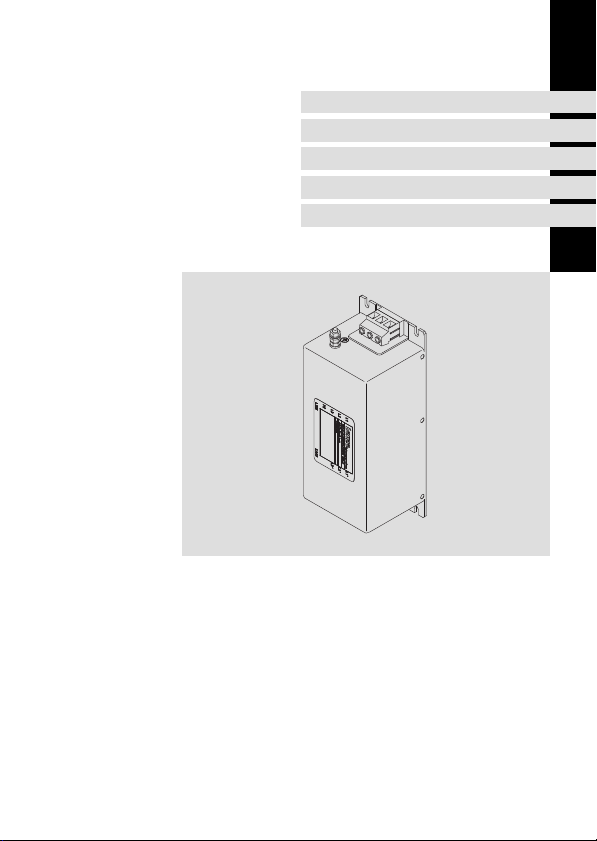
Funk−Entstörfilter
RFI filter
Filtre antiparasite
l
Page 2

, Lesen Sie zuerst diese Anleitung und die Dokumentation zum Grundgerät,
bevor Sie mit den Arbeiten beginnen!
Beachten Sie die enthaltenen Sicherheitshinweise.
, Please read these instructions and the documentation of the standard
device before you start working!
Observe the safety instructions given therein!
, Lire le présent fascicule et la documentation relative à l’appareil de base
avant toute manipulation de l’équipement !
Respecter les consignes de sécurité fournies.
Page 3

Inhalt i
1 Über diese Dokumentation 4 . . . . . . . . . . . . . . . . . . . . . . . . . . . . . . . . . . . . . . . . . .
Informationen zur Gültigkeit 4 . . . . . . . . . . . . . . . . . . . . . . . . . . . . . . . . . . . . . . . . .
Zielgruppe 4 . . . . . . . . . . . . . . . . . . . . . . . . . . . . . . . . . . . . . . . . . . . . . . . . . . . . . . . .
Dokumenthistorie 5 . . . . . . . . . . . . . . . . . . . . . . . . . . . . . . . . . . . . . . . . . . . . . . . . . .
Verwendete Konventionen 5 . . . . . . . . . . . . . . . . . . . . . . . . . . . . . . . . . . . . . . . . . .
Verwendete Hinweise 6 . . . . . . . . . . . . . . . . . . . . . . . . . . . . . . . . . . . . . . . . . . . . . . .
2 Sicherheitshinweise 8 . . . . . . . . . . . . . . . . . . . . . . . . . . . . . . . . . . . . . . . . . . . . . . . .
Allgemeine Sicherheitshinweise 8 . . . . . . . . . . . . . . . . . . . . . . . . . . . . . . . . . . . . . .
Restgefahren 9 . . . . . . . . . . . . . . . . . . . . . . . . . . . . . . . . . . . . . . . . . . . . . . . . . . . . . .
3 Produktbeschreibung 11 . . . . . . . . . . . . . . . . . . . . . . . . . . . . . . . . . . . . . . . . . . . . . . .
Lieferumfang 11 . . . . . . . . . . . . . . . . . . . . . . . . . . . . . . . . . . . . . . . . . . . . . . . . . . . . . .
Übersicht 11 . . . . . . . . . . . . . . . . . . . . . . . . . . . . . . . . . . . . . . . . . . . . . . . . . . . . . . . . .
Identifikation 12 . . . . . . . . . . . . . . . . . . . . . . . . . . . . . . . . . . . . . . . . . . . . . . . . . . . . . .
Einsatzbedingungen 13 . . . . . . . . . . . . . . . . . . . . . . . . . . . . . . . . . . . . . . . . . . . . . . . .
4 Technische Daten 14 . . . . . . . . . . . . . . . . . . . . . . . . . . . . . . . . . . . . . . . . . . . . . . . . . .
Allgemeine Daten und Einsatzbedingungen 14 . . . . . . . . . . . . . . . . . . . . . . . . . . .
Bemessungsdaten 15 . . . . . . . . . . . . . . . . . . . . . . . . . . . . . . . . . . . . . . . . . . . . . . . . . .
Mechanische Daten 16 . . . . . . . . . . . . . . . . . . . . . . . . . . . . . . . . . . . . . . . . . . . . . . .
5 Mechanische Installation 17 . . . . . . . . . . . . . . . . . . . . . . . . . . . . . . . . . . . . . . . . . . . .
Wichtige Hinweise 17 . . . . . . . . . . . . . . . . . . . . . . . . . . . . . . . . . . . . . . . . . . . . . . . . .
Anordnung der Geräte 17 . . . . . . . . . . . . . . . . . . . . . . . . . . . . . . . . . . . . . . . . . . . . . .
Bohrplan 18 . . . . . . . . . . . . . . . . . . . . . . . . . . . . . . . . . . . . . . . . . . . . . . . . . . . . . . . . .
Montageschritte 19 . . . . . . . . . . . . . . . . . . . . . . . . . . . . . . . . . . . . . . . . . . . . . . . . . . .
6 Elektrische Installation 20 . . . . . . . . . . . . . . . . . . . . . . . . . . . . . . . . . . . . . . . . . . . . . .
Wichtige Hinweise 20 . . . . . . . . . . . . . . . . . . . . . . . . . . . . . . . . . . . . . . . . . . . . . . . . .
Anschlussplan 21 . . . . . . . . . . . . . . . . . . . . . . . . . . . . . . . . . . . . . . . . . . . . . . . . . . . . .
Anschlussdaten 22 . . . . . . . . . . . . . . . . . . . . . . . . . . . . . . . . . . . . . . . . . . . . . . . . . . . .
Montageschritte 23 . . . . . . . . . . . . . . . . . . . . . . . . . . . . . . . . . . . . . . . . . . . . . . . . . . .
EDKCSZZ040 DE/EN/FR 3.1
l
3
Page 4

1 Über diese Dokumentation
Informationen zur Gültigkeit
0Abb. 0Tab. 0
1 Über diese Dokumentation
Informationen zur Gültigkeit
Diese Anleitung ist gültig für
ƒ Funk−Entstörfilter ECSZZ...
Zielgruppe
Diese Dokumentation richtet sich an qualifiziertes Fachpersonal nach IEC 364.
Qualifiziertes Fachpersonal sind Personen, die für die auszuführenden Tätigkeiten bei der
Aufstellung, Montage, Inbetriebsetzung und dem Betrieb des Produkts über entsprechende
Qualifikationen verfügen.
I Tipp!
Dokumentationen und Software−Updates zu weiteren Lenze Produkten finden
Sie im Internet im Bereich "Services & Downloads" unter
http://www.Lenze.com
4
l
EDKCSZZ040 DE/EN/FR 3.1
Page 5

Über diese Dokumentation
Dokumenthistorie
Dokumenthistorie
Materialnummer Version Beschreibung
.#ZG 1.0 01/2005 TD17 Erstausgabe
.6aU 2.0 08/2007 TD29 Überarbeitung
.A]4 3.0 01/2010 TD29 Layout−Anpassung und Überarbeitung
.A]4 3.1 03/2010 TD29 Neuauflage wegen Neuorganisation des Un-
Verwendete Konventionen
Informationsart Auszeichnung Beispiele/Hinweise
Zahlenschreibweise
Dezimaltrennzeichen
Warnhinweise
UL−Warnhinweise
UR−Warnhinweise
Textauszeichnung
Programmname » « PC−Software
Symbole
Seitenverweis
ternehmens
Punkt Es wird generell der Dezimalpunkt
J
O
^
verwendet.
Zum Beispiel: 1234.56
Werden nur in der englischen Sprache
verwendet.
Zum Beispiel: »Engineer«
Verweis auf eine andere Seite mit zusätzlichen Informationen
Zum Beispiel: ^ 16 = siehe Seite 16
1
EDKCSZZ040 DE/EN/FR 3.1
l
5
Page 6

1 Über diese Dokumentation
Verwendete Hinweise
Verwendete Hinweise
Um auf Gefahren und wichtige Informationen hinzuweisen, werden in dieser Dokumentation folgende Piktogramme und Signalwörter verwendet:
Sicherheitshinweise
Aufbau der Sicherheitshinweise:
} Gefahr!
(kennzeichnet die Art und die Schwere der Gefahr)
Hinweistext
(beschreibt die Gefahr und gibt Hinweise, wie sie vermieden werden kann)
Piktogramm und Signalwort Bedeutung
Gefahr von Personenschäden durch gefährliche elektri-
{ Gefahr!
} Gefahr!
( Stop!
sche Spannung
Hinweis auf eine unmittelbar drohende Gefahr, die den
Tod oder schwere Verletzungen zur Folge haben kann,
wenn nicht die entsprechenden Maßnahmen getroffen
werden.
Gefahr von Personenschäden durch eine allgemeine Gefahrenquelle
Hinweis auf eine unmittelbar drohende Gefahr, die den
Tod oder schwere Verletzungen zur Folge haben kann,
wenn nicht die entsprechenden Maßnahmen getroffen
werden.
Gefahr von Sachschäden
Hinweis auf eine mögliche Gefahr, die Sachschäden zur
Folge haben kann, wenn nicht die entsprechenden Maßnahmen getroffen werden.
6
l
EDKCSZZ040 DE/EN/FR 3.1
Page 7

Anwendungshinweise
Piktogramm und Signalwort Bedeutung
Über diese Dokumentation
Verwendete Hinweise
1
) Hinweis!
I Tipp!
,
Wichtiger Hinweis für die störungsfreie Funktion
Nützlicher Tipp für die einfache Handhabung
Verweis auf andere Dokumentation
EDKCSZZ040 DE/EN/FR 3.1
l
7
Page 8

2 Sicherheitshinweise
Allgemeine Sicherheitshinweise
2 Sicherheitshinweise
Allgemeine Sicherheitshinweise
} Gefahr!
Wenn Sie die folgenden grundlegenden Sicherheitsmaßnahmen missachten,
kann dies zu schweren Personenschäden und Sachschäden führen:
ƒ Lenze−Antriebskomponenten ...
– ... ausschließlich bestimmungsgemäß verwenden.
– ... niemals trotz erkennbarer Schäden in Betrieb nehmen.
– ... niemals technisch verändern.
– ... niemals unvollständig montiert in Betrieb nehmen.
– ... niemals ohne erforderliche Abdeckungen betreiben.
– ... können während des Betriebs − ihrer Schutzart entsprechend −
spannungsführende, auch bewegliche oder rotierende Teile haben. Oberflächen
können heiß sein.
ƒ Für Lenze−Antriebskomponenten ...
– ... nur das zugelassene Zubehör verwenden.
– ... nur Original−Ersatzteile des Herstellers verwenden.
ƒ Alle Vorgaben der beiliegenden und zugehörigen Dokumentation beachten.
– Dies ist Voraussetzung für einen sicheren und störungsfreien Betrieb sowie für das
Erreichen der angegebenen Produkteigenschaften.
– Die in diesem Dokument dargestellten verfahrenstechnischen Hinweise und
Schaltungsausschnitte sind Vorschläge, deren Übertragbarkeit auf die jeweilige
Anwendung überprüft werden muss. Für die Eignung der angegebenen Verfahren
und Schaltungsvorschläge übernimmt der Hersteller keine Gewähr.
ƒ Alle Arbeiten mit und an Lenze−Antriebskomponenten darf nur qualifiziertes
Fachpersonal ausführen.
Nach IEC 60364 bzw. CENELEC HD 384 sind dies Personen, ...
– ... die mit Aufstellung, Montage, Inbetriebsetzung und Betrieb des Produkts
vertraut sind.
– ... die über die entsprechenden Qualifikationen für ihre Tätigkeit verfügen.
– ... die alle am Einsatzort geltenden Unfallverhütungsvorschriften, Richtlinien und
Gesetze kennen und anwenden können.
8
l
EDKCSZZ040 DE/EN/FR 3.1
Page 9

Sicherheitshinweise
Restgefahren
{ Gefahr!
Gefährliche elektrische Spannung
Alle Leistungsanschlüsse führen bis zu 3 Minuten nach Netz−Ausschalten
gefährliche elektrische Spannung.
Mögliche Folgen:
ƒ Tod oder schwere Verletzungen beim Berühren der Leistungsanschlüsse.
Schutzmaßnahmen:
ƒ Vor Arbeiten an den Leistungsanschlüssen Netz abschalten und
mindestens 3 Minuten warten.
ƒ Prüfen, ob alle Leistungsanschlüsse spannungsfrei sind.
{ Gefahr!
Gefährliche elektrische Spannung
Der Ableitstrom gegen Erde (PE) ist > 3.5 mA AC bzw. > 10 mA DC.
Mögliche Folgen:
ƒ Tod oder schwere Verletzungen beim Berühren des Gerätes im Fehlerfall.
Schutzmaßnahmen:
ƒ Die in der EN 61800−5−1 geforderten Maßnahmen umsetzen.
Insbesondere:
– Festinstallation
– PE−Anschluss normgerecht ausführen (PE−Leiterdurchmesser ³ 10 mm
oder PE−Leiter doppelt auflegen)
Restgefahren
2
2
EDKCSZZ040 DE/EN/FR 3.1
l
9
Page 10

2 Sicherheitshinweise
Restgefahren
( Stop!
Kein Geräteschutz gegen zu hohe Netzspannung
Der Netzeingang ist intern nicht abgesichert.
Mögliche Folgen:
ƒ Zerstörung des Gerätes bei zu hoher Netzspannung.
Schutzmaßnahmen:
ƒ Beachten Sie die maximal zulässige Netzspannung.
ƒ Sichern Sie das Gerät netzseitig fachgerecht gegen Netzschwankungen
und Spannungsspitzen ab.
O Warnings!
Conditions of Acceptability:
ƒ The equipment leakage current in the grounding conductor should be
measured to detemine compliance with the end use requirements.
Suitability of the leakage current values must be determined in the
end−use application.
ƒ Electrical spacings between uninsulated live metal parts and unsinsulated
dead metal parts should be in accordance with the end use product.
ƒ The terminals have not been investigated for field wiring use.
ƒ The insulation system for the inductor windings have only been evaluated
for a Class 105 insulation system.
ƒ When the filter air ambient temperature in the end use product differs
significantly from 40 °C, consideration should be given to conducting a
temperature test with the filter installed in the end use product.
ƒ The suitability of the grounding means, in conjunction with the filter, shall
be evaluated in the end use product.
ƒ The filter should be provided with an overall enclosure suitable for the
applicable end product requirements.
ƒ Case temperature should be monitored in the end product.
ƒ The filter exceeded the voltage allowed after a view seconds during the
Capacitor Discharge Test, Section 37, of UL 1283. Bleeder resistors may be
necessary in the end−product to comply with the applicable end−product
requirements.
10
l
EDKCSZZ040 DE/EN/FR 3.1
Page 11
3 Produktbeschreibung
Lieferumfang
Anzahl Beschreibung
1 Filter
1 Montageanleitung
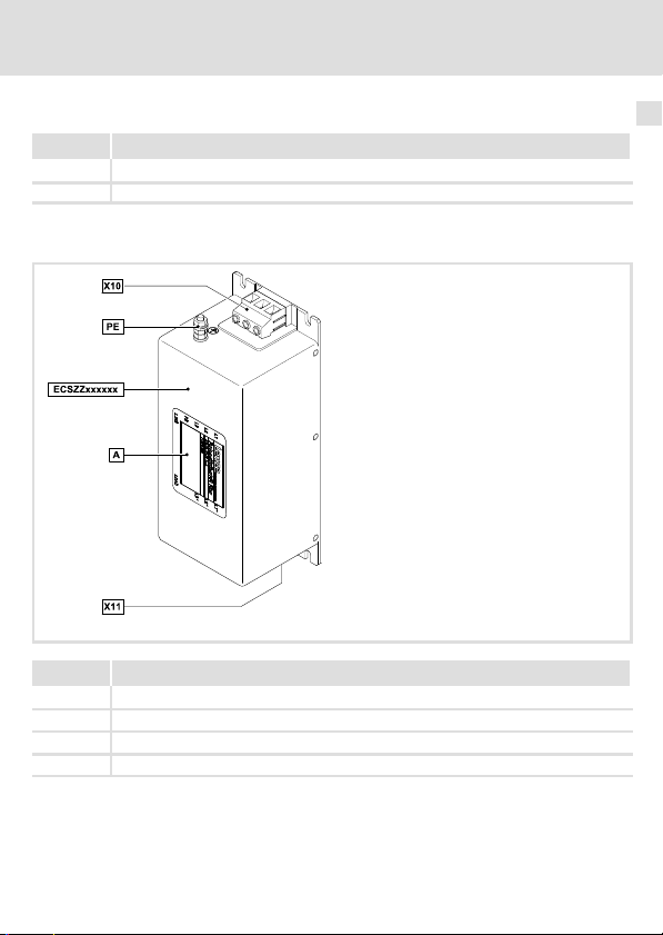
Übersicht
Position Beschreibung
PE PE−Anschlussbolzen
X10 Netzanschluss (L1 ... L3)
X11 Anschluss zum Versorgungsmodul ECSxE... (L1’ ... L3’)
0
Typenschild
Produktbeschreibung
Lieferumfang
ECSZZ020_001A
3
EDKCSZZ040 DE/EN/FR 3.1
l
11
Page 12
3 Produktbeschreibung
Identifikation
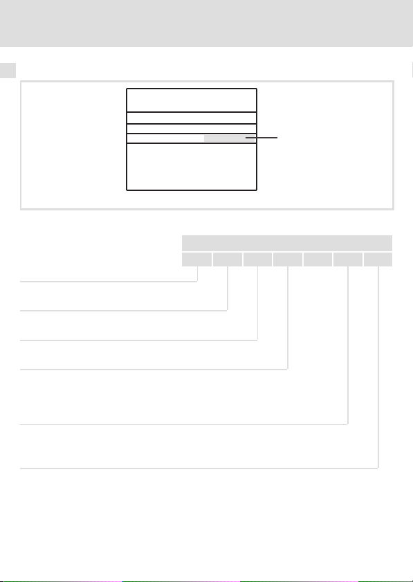
Identifikation
Abb. 1 Typenschild
Typenschlüssel
Produktreihe
Zubehör
Typ Funk−Entstörfilter
Bemessungsstrom
020 = 16 A
040 = 32 A
Spannungsklasse
4 = 500 V
Technische Ausführung
B = Standard
l
Art.Nr./Part no.:
Typ/type:
Hans-Lenze-Straße 1, D-31855 Aerzen
ECSZZ002
ECS Z Z xxx X 4 B
12
l
EDKCSZZ040 DE/EN/FR 3.1
Page 13

Produktbeschreibung
Einsatzbedingungen
Einsatzbedingungen
Verwenden Sie den Funk−Entstörfilter ECSZZ... nur mit Versorgungsmodulen der Reihe ECS
ab dem Geräte−Typ:
Geräte−Typ ECSxExxxx
Hardware−Version VA oder höher
Zuordnung Filter ˘ Grundgerät
Funk−Entstörfilter Typ ECS−Versorgungsmodul Typ
ECSZZ020X4B
ECSZZ040X4B ECSxE040
ECSxE012
ECSxE020
3
EDKCSZZ040 DE/EN/FR 3.1
l
13
Page 14

4 Technische Daten
Allgemeine Daten und Einsatzbedingungen
4 Technische Daten
Allgemeine Daten und Einsatzbedingungen
Normen
Approbation
Angaben zu Netzen
Netzformen
Mit geerdetem Y−Punkt (TT−/TN−Netze) Betrieb uneingeschränkt erlaubt
Andere Netzformen Anweisungen über besondere Maßnahmen in der Do-
Schutz
Schutzart
Isolationsfestigkeit EN 61800−5−1 Überspannungskategorie III
Ableitstrom EN 61800−5−1 > 3.5 mA Bestimmungen und
Umweltbedingungen
Temperatur
Lagerung −25 ... +60 °C
Transport −25 ... +70 °C
Betrieb −10 ... +55 °C
Aufstellhöhe 0 ... 4000 m üNN
Verschmutzung EN 61800−5−1 Verschmutzungsgrad 2
Rüttelfestigkeit EN50178;
UL 1283 Standard for Electromagnetic Interference Filters (File
EN 60529
NEMA 250 Berührschutz nach Typ 1
IEC61800−5−1;
Germanischer
Loyd, allgemeine
Bedingungen
No. E70122) for USA
kumentation zum Grundgerät beachten!
IP 20
Reduzierung ab 2000 m: Überspannungskategorie II
Stromreduzierung von +40 ... +55 °C: 2.5 %/°C
1000 ... 4000 m üNN: Stromreduzierung 5 %/1000 m
Beschleunigungsfest bis 1 g
nicht im Anschlussbereich der Klemmen
Sicherheitshinweise
beachten!
14
l
EDKCSZZ040 DE/EN/FR 3.1
Page 15
Technische Daten
Bemessungsdaten
Montagebedingungen
Montageort im Schaltschrank
Montageposition links neben dem Grundgerät
Einbaulage senkrecht, Netzanschlüsse oben
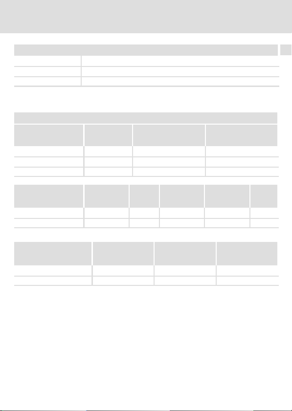
Bemessungsdaten
Grundlage der Daten
Netz Spannung Spannungsbereich Frequenzbereich
U
[V] U
3/PE AC 230 180 − 0 % ... 264 + 0 % 45 − 0 % ... 65 + 0 %
3/PE AC 400 320 − 0 % ... 440 + 0 % 45 − 0 % ... 65 + 0 %
3/PE AC 480 432 − 0 % ... 528 + 0 % 45 ... 65
LN
[V] f [Hz]
LN
4
Spannung Freq. Strom [A] Strom [A]
[V] [Hz]
ECSZZ020x4B 230/400/480 50/60 16/16/16 10/10/10 3
ECSZZ040x4B 230/400/480 50/60 32/32/32 20/20/20 3
Temperatur im Schaltschrank
Verlustleistung Induktivität Spannungsabfall
PV [W] L [mH]
ECSZZ020x4B 6.2 − −
ECSZZ040x4B 9.3 − −
EDKCSZZ040 DE/EN/FR 3.1
l
max. +40° C max. +55° C
DU [V]
Phasen-
zahl
15
Page 16
4 Technische Daten
Mechanische Daten
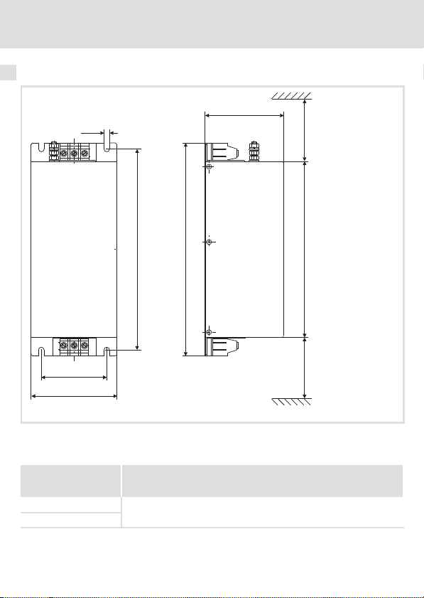
Mechanische Daten
6.6
96
>70
245
80
105
Abb. 2 Abmessungen Filter
Alle Maße in Millimeter.
ECSZZ020x4B
ECSZZ040x4B
16
260
l
215
>70
ECSZZ001
Masse
[kg]
3.0
EDKCSZZ040 DE/EN/FR 3.1
Page 17
Mechanische Installation
Wichtige Hinweise
5 Mechanische Installation
Wichtige Hinweise
ƒ Der Montageort muss den in den Technischen Daten genannten Einsatzbedingungen
immer entsprechen (^ 14). Ggf. zusätzliche Maßnahmen ergreifen.
ƒ Die Montageplatte des Schaltschranks muss folgende Eigenschaften aufweisen:
– elektrisch leitfähig
– lackfrei
ƒ Die mechanischen Verbindungen müssen immer gewährleistet sein.
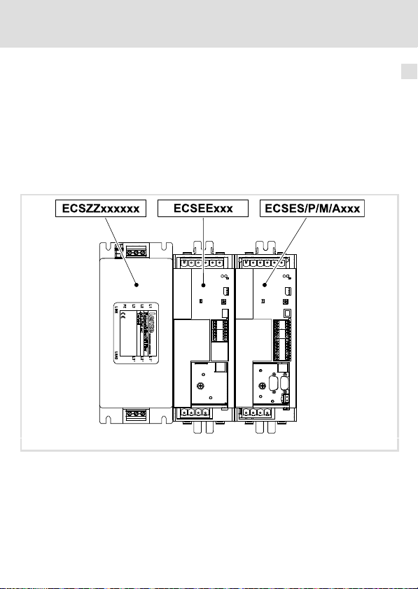
Anordnung der Geräte
5
Abb. 3 Anordnung ECS−Geräte
EDKCSZZ040 DE/EN/FR 3.1
l
ECSZZ020_002A
17
Page 18
5 Mechanische Installation
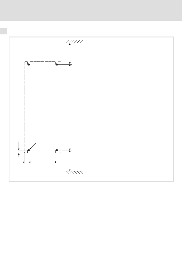
Bohrplan
Bohrplan
>55
245
M6
7.5
18
12.5
80
>55
l
ECSZZ006
EDKCSZZ040 DE/EN/FR 3.1
Page 19
Mechanische Installation
Montageschritte
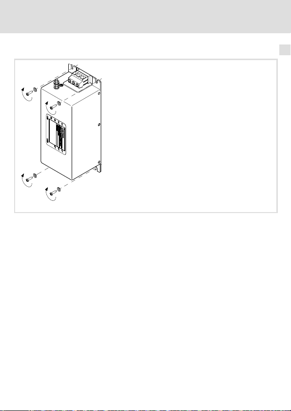
Montageschritte
ECSZZ004
Abb. 4 Montage des Filters
So montieren Sie das Filter:
1. Montageplatte gemäß Bohrplan vorbereiten.
2. Filter mit vier Schrauben M6 und Unterlegscheiben auf Montageplatte montieren.
5
EDKCSZZ040 DE/EN/FR 3.1
l
19
Page 20

6 Elektrische Installation
Wichtige Hinweise
6 Elektrische Installation
Wichtige Hinweise
ƒ Die Installation muss
– den in den Technischen Daten genannten Einsatzbedingungen immer
entsprechen (^ 14).
– nach EN 60204−1 ausgeführt werden.
ƒ Bei der Auswahl des Leitungstyps beachten:
– Die verwendeten Leitungen müssen den geforderten Approbationen am
Einsatzort entsprechen (z. B. VDE, UL usw.).
– Absicherung und Leitungsquerschnitte gemäß den Vorgaben in der
Dokumentation zum Grundgerät bemessen.
ƒ Beim Verlegen der Leitungen zwischen Funk−Entstörfilter und Versorgungsmodul
beachten:
– Leitungslänge < 30 cm: ungeschirmte Leitungen verlegen
– Leitungslänge > 30 cm: geschirmte Leitung verlegen und Länge möglichst kurz
halten.
ƒ Beim Verlegen der Netzleitungen beachten:
– Netzleitungen und ±UG−Leitungen dürfen sich nicht berühren.
– Bei paralleler Verlegung der Netzleitungen und ±UG−Leitungen einen Abstand von
>150 mm einhalten.
ƒ Beim Verlegen der PE−Leitung beachten:
– Der PE−Anschluss muss nach EN 61800−5−1 ausgeführt werden.
20
l
EDKCSZZ040 DE/EN/FR 3.1
Page 21
Elektrische Installation
Anschlussplan
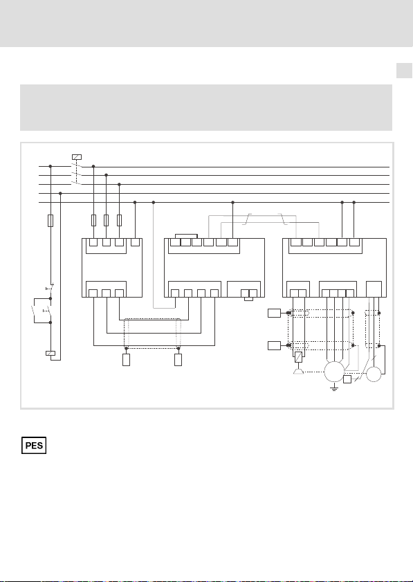
, Beachten Sie ...
die Hinweise in der ausführlichen Dokumentation des Versorgungsmoduls.
K1
L1
L2
L3
N
PE
F1...F3
F4
L2
L1
L3
PE
X10
ECSZZ...
Off
On
K1
X11
L2’
L1’
L3’
R
BR0
BR1
PE
B_int
+UG
+UG
X22
ECSxE...
X21
L2
L3
PE
-UG
X6
...
T2
T1
L1
PES
Anschlussplan
PE
-UG
PE
+UG
-UG
+UG
X23
ECSxS/P/M/A...
X24
X25
B2
B1
UV
PE
W
6
X7
0
K1
PES
PES
Abb. 5 Verdrahtung Funk−Entstörfilter ECSZZ...
Leitungslänge > 30 cm: HF−Schirmabschluss durch großflächige PE−Anbindung
K1 Netzschütz
F1 ... F4 Absicherung
R
0
EDKCSZZ040 DE/EN/FR 3.1
Verdrahtung Bremswiderstand (siehe ausführliche Dokumentation ECSxE...)
B_int
Systemleitung ˘ Rückführung
l
PES
M
3~
PE
J
2
ECSZZ003
6
R
21
Page 22

6 Elektrische Installation
Anschlussdaten
Anschlussdaten
Klemmen X10 und X11
[mm2]
[AWG]
ECSZZxxxxxx
PE−Gewindebolzen
0.2 ... 10
24 ...8
ECSZZxxxxxx M6 x 24 6.7 SW 10
0.2 ... 6
0.2 ... 5
24 ... 8
22 ... 10
x
[mm] [mm] [Nm]
24 ... 4
22 ... 12
!
[Nm]
[lb−in]
1.2 ... 1.5
10.6 ... 13.3
[lb−in]
4.3 ... 5.3
38.3 ... 46.7
22
l
EDKCSZZ040 DE/EN/FR 3.1
Page 23

Elektrische Installation
Montageschritte
Montageschritte
ECSZZ005
Abb. 6 Anschlüsse des Filters
So schließen Sie das Filter an:
1. Schaltschrank spannungsfrei schalten und gegen Wiedereinschalten sichern.
2. Filter−Ausgangsleitungen (X11) an Klemme X21 des Versorgungsmoduls ECSxE...
anschließen.
– Dokumentation zum Versorgungsmodul ECSxE... beachten.
3. Netzleitungen an Klemme X10 anschließen.
– Anzugsmoment beachten.
4. PE−Leiter mit Ringkabelschuh an PE−Schraube montieren.
– Anzugsmoment beachten.
6
EDKCSZZ040 DE/EN/FR 3.1
l
23
Page 24

6 Elektrische Installation
Montageschritte
24
l
EDKCSZZ040 DE/EN/FR 3.1
Page 25

Contents i
1 About this documentation 26 . . . . . . . . . . . . . . . . . . . . . . . . . . . . . . . . . . . . . . . . . . .
Validity information 26 . . . . . . . . . . . . . . . . . . . . . . . . . . . . . . . . . . . . . . . . . . . . . . . .
Target group 26 . . . . . . . . . . . . . . . . . . . . . . . . . . . . . . . . . . . . . . . . . . . . . . . . . . . . . .
Document history 26 . . . . . . . . . . . . . . . . . . . . . . . . . . . . . . . . . . . . . . . . . . . . . . . . . .
Conventions used 27 . . . . . . . . . . . . . . . . . . . . . . . . . . . . . . . . . . . . . . . . . . . . . . . . . .
Notes used 28 . . . . . . . . . . . . . . . . . . . . . . . . . . . . . . . . . . . . . . . . . . . . . . . . . . . . . . . .
2 Safety instructions 30 . . . . . . . . . . . . . . . . . . . . . . . . . . . . . . . . . . . . . . . . . . . . . . . . .
General safety information 30 . . . . . . . . . . . . . . . . . . . . . . . . . . . . . . . . . . . . . . . . . .
Residual hazards 31 . . . . . . . . . . . . . . . . . . . . . . . . . . . . . . . . . . . . . . . . . . . . . . . . . . .
3 Product description 33 . . . . . . . . . . . . . . . . . . . . . . . . . . . . . . . . . . . . . . . . . . . . . . . . .
Scope of supply 33 . . . . . . . . . . . . . . . . . . . . . . . . . . . . . . . . . . . . . . . . . . . . . . . . . . . .
Overview 33 . . . . . . . . . . . . . . . . . . . . . . . . . . . . . . . . . . . . . . . . . . . . . . . . . . . . . . . . .
Identification 34 . . . . . . . . . . . . . . . . . . . . . . . . . . . . . . . . . . . . . . . . . . . . . . . . . . . . . .
Operating conditions 35 . . . . . . . . . . . . . . . . . . . . . . . . . . . . . . . . . . . . . . . . . . . . . . .
4 Technical data 36 . . . . . . . . . . . . . . . . . . . . . . . . . . . . . . . . . . . . . . . . . . . . . . . . . . . . .
General data and operating conditions 36 . . . . . . . . . . . . . . . . . . . . . . . . . . . . . . .
Rated data 37 . . . . . . . . . . . . . . . . . . . . . . . . . . . . . . . . . . . . . . . . . . . . . . . . . . . . . . . .
Mechanical data 38 . . . . . . . . . . . . . . . . . . . . . . . . . . . . . . . . . . . . . . . . . . . . . . . . . .
5 Mechanical installation 39 . . . . . . . . . . . . . . . . . . . . . . . . . . . . . . . . . . . . . . . . . . . . .
Important notes 39 . . . . . . . . . . . . . . . . . . . . . . . . . . . . . . . . . . . . . . . . . . . . . . . . . . .
Arrangement of the devices 39 . . . . . . . . . . . . . . . . . . . . . . . . . . . . . . . . . . . . . . . . . .
Drilling pattern 40 . . . . . . . . . . . . . . . . . . . . . . . . . . . . . . . . . . . . . . . . . . . . . . . . . . . .
Mounting steps 41 . . . . . . . . . . . . . . . . . . . . . . . . . . . . . . . . . . . . . . . . . . . . . . . . . . . .
6 Electrical installation 42 . . . . . . . . . . . . . . . . . . . . . . . . . . . . . . . . . . . . . . . . . . . . . . .
Important notes 42 . . . . . . . . . . . . . . . . . . . . . . . . . . . . . . . . . . . . . . . . . . . . . . . . . . .
Connection plan 43 . . . . . . . . . . . . . . . . . . . . . . . . . . . . . . . . . . . . . . . . . . . . . . . . . . .
Connection data 44 . . . . . . . . . . . . . . . . . . . . . . . . . . . . . . . . . . . . . . . . . . . . . . . . . . .
Mounting steps 45 . . . . . . . . . . . . . . . . . . . . . . . . . . . . . . . . . . . . . . . . . . . . . . . . . . . .
EDKCSZZ040 DE/EN/FR 3.1
l
25
Page 26

1 About this documentation
Validity information
0Fig. 0Tab. 0
1 About this documentation
Validity information
These instructions are valid for
ƒ ECSZZ... RFI filters.
Target group
This documentation is intended for qualified personnel according to IEC 364.
Qualified, skilled personnel are persons who have the qualifications necessary for the work
activities to be undertaken during the assembly, installation, comissioning, and operation
of the product.
I Tip!
Documentation and software updates for further Lenze products can be found
on the Internet in the "Services & Downloads" area under
http://www.Lenze.com
Document history
Material number Version Description
.#ZG 1.0 01/2005 TD17 First edition
.6aU 2.0 08/2007 TD29 Revision
.A]4 3.0 01/2010 TD29 Layout adaption and revision
.A]4 3.1 03/2010 TD29 New edition due to reorganisation of the
company
26
l
EDKCSZZ040 DE/EN/FR 3.1
Page 27

About this documentation
Conventions used
Conventions used
Type of information Identification Examples/notes
Spelling of numbers
Decimal separator
Warnings
UL warnings
UR warnings
Text
Program name » « PC software
Icons
Page reference
Point In general, the decimal point is used.
J
For instance: 1234.56
Are only given in English.
O
For example: »Engineer«
^
Reference to another page with
additional information
For instance:
1
^ 16 = see page 16
EDKCSZZ040 DE/EN/FR 3.1
l
27
Page 28

1 About this documentation
Notes used
Notes used
The following pictographs and signal words are used in this documentation to indicate
dangers and important information:
Safety instructions
Structure of safety instructions:
} Danger!
(characterises the type and severity of danger)
Note
(describes the danger and gives information about how to prevent dangerous
situations)
Pictograph and signal word Meaning
{ Danger!
} Danger!
( Stop!
Danger of personal injury through dangerous electrical
voltage.
Reference to an imminent danger that may result in
death or serious personal injury if the corresponding
measures are not taken.
Danger of personal injury through a general source of
danger.
Reference to an imminent danger that may result in
death or serious personal injury if the corresponding
measures are not taken.
Danger of property damage.
Reference to a possible danger that may result in
property damage if the corresponding measures are not
taken.
28
l
EDKCSZZ040 DE/EN/FR 3.1
Page 29

Application notes
Pictograph and signal word Meaning
About this documentation
Notes used
1
) Note!
I Tip!
,
Important note to ensure troublefree operation
Useful tip for simple handling
Reference to another documentation
EDKCSZZ040 DE/EN/FR 3.1
l
29
Page 30

2 Safety instructions
General safety information
2 Safety instructions
General safety information
} Danger!
Disregarding the following basic safety measures may lead to severe personal
injury and damage to material!
ƒ Lenze drive components ...
– ... must only be used as directed.
– ... must never be commissioned in the event of visible damage.
– ... must never be technically modified.
– ... must never be commissioned before they have been completely mounted.
– ... must never be operated without the covers required.
– ... can − depending on the degree of protection − have live, movable or rotating
parts during operation. Surfaces can be hot.
ƒ For Lenze drive components ...
– ... use only the accessories approved.
– ... use only original spare parts from Lenze.
ƒ Observe all specifications given in the attached documentation.
– This is the prerequisite for safe and trouble−free operation and achieving the
specified product features.
– The specifications, processes, and circuitry described in this document are for
guidance only and must be adapted to your own application. Lenze does not take
responsibility for the suitability of the process and circuit proposals.
ƒ Only qualified personnel may work with and on Lenze drive components.
According to IEC 60364 and CENELEC HD 384, these are persons ...
– ... who are familiar with the installation, assembly, commissioning and operation
of the product.
– ... who have the corresponding qualifications for their work.
– ... who know all regulations for the prevention of accidents, directives and laws
applicable on site and are able to apply them.
30
l
EDKCSZZ040 DE/EN/FR 3.1
Page 31

Safety instructions
Residual hazards
Residual hazards
{ Danger!
Dangerous electrical voltage
All power terminals remain live for up to three minutes after mains
disconnection.
Possible consequences:
ƒ Death or severe injuries when touching the power terminals.
Protective measures:
ƒ Switch off the power supply and wait for at least three minutes before
working on the power terminals.
ƒ Make sure that all power terminals are deenergised.
{ Danger!
Dangerous voltage
The leakage current to earth (PE) is > 3.5 mA AC or > 10 mA DC.
Possible consequences:
ƒ Death or severe injuries when the device is touched in the event of a fault.
Protective measures:
ƒ Implement the actions required in the EN 61800−5−1. Especially:
– Fixed installation
– PE connection must conform to standards (PE conductor diameter
2
³ 10 mm
or PE conductor must be connected twice)
2
EDKCSZZ040 DE/EN/FR 3.1
l
31
Page 32

2 Safety instructions
Residual hazards
( Stop!
No device protection if the mains voltage is too high
The mains input is not internally fused.
Possible consequences:
ƒ Destruction of the device if the mains voltage is too high.
Protective measures:
ƒ Observe the maximally permissible mains voltage.
ƒ Fuse the device correctly on the supply side against mains fluctuations and
voltage peaks.
O Warnings!
Conditions of Acceptability:
ƒ The equipment leakage current in the grounding conductor should be
measured to detemine compliance with the end use requirements.
Suitability of the leakage current values must be determined in the
end−use application.
ƒ Electrical spacings between uninsulated live metal parts and unsinsulated
dead metal parts should be in accordance with the end use product.
ƒ The terminals have not been investigated for field wiring use.
ƒ The insulation system for the inductor windings have only been evaluated
for a Class 105 insulation system.
ƒ When the filter air ambient temperature in the end use product differs
significantly from 40 °C, consideration should be given to conducting a
temperature test with the filter installed in the end use product.
ƒ The suitability of the grounding means, in conjunction with the filter, shall
be evaluated in the end use product.
ƒ The filter should be provided with an overall enclosure suitable for the
applicable end product requirements.
ƒ Case temperature should be monitored in the end product.
ƒ The filter exceeded the voltage allowed after a view seconds during the
Capacitor Discharge Test, Section 37, of UL 1283. Bleeder resistors may be
necessary in the end−product to comply with the applicable end−product
requirements.
32
l
EDKCSZZ040 DE/EN/FR 3.1
Page 33

Product description
3 Product description
Scope of supply
Quantity Description
1 Filter
1 Mounting Instructions
Overview
Position Description
PE PE terminal stud
X10 Mains connection (L1 ... L3)
X11 Connection to the power supply module ECSxE... (L1’ ... L3’)
0
Nameplate
Scope of supply
3
ECSZZ020_001A
EDKCSZZ040 DE/EN/FR 3.1
l
33
Page 34

3 Product description
Identification
Identification
Fig. 1 Nameplate
Type code
Product range
Accessories
RFI filter type
Rated current
020 = 16 A
040 = 32 A
Voltage class
4 = 500 V
Technical version
B = Standard
l
Art.Nr./Part no.:
Typ/type:
Hans-Lenze-Straße 1, D-31855 Aerzen
ECSZZ002
ECS Z Z xxx X 4 B
34
l
EDKCSZZ040 DE/EN/FR 3.1
Page 35

Product description
Operating conditions
Operating conditions
The RFI filter ECSZZ... may only be used together with the power supply modules of the ECS
series as of device type:
Device type ECSxExxxx
Hardware version VA or higher
Assignment of filters to standard devices
RFI filter type ECS power supply module type
ECSZZ020X4B
ECSZZ040X4B ECSxE040
ECSxE012
ECSxE020
3
EDKCSZZ040 DE/EN/FR 3.1
l
35
Page 36

4 Technical data
General data and operating conditions
4 Technical data
General data and operating conditions
Standards
Approval
Mains data
Mains types
With grounded neutral (TT/TN systems) Operation permitted without restrictions
Other mains types Observe instructions for special measures in the
Protection
Type of protection
Insulation resistance EN 61800−5−1 Overvoltage category III
Leakage current EN 61800−5−1 > 3.5 mA Observe regulations
Ambient conditions
Temperature
Storage −25 ... +60 °C
Transport −25 ... +70 °C
Operation −10 ... +55 °C
Site altitude 0 ... 4000 m amsl
Pollution EN 61800−5−1 Pollution degree 2
Vibration resistance EN 50178; IEC
UL 1283 Standard for Electromagnetic Interference Filters (File
EN 60529
NEMA 250 Protection against contact to
61800−5−1;
Germanischer
Lloyd, general
conditions
No. E70122) for USA
documentation for the basic device!
IP 20
type 1
> 2000 m: Overvoltage category II
Current derating from +40 to +55 °C: 2.5 %/°C
1000 ... 4000 m amsl: Current derating by 5 %/1000 m
Acceleration−resistant up to 1 g
Not in the wire range of
the terminals
and safety instructions!
36
l
EDKCSZZ040 DE/EN/FR 3.1
Page 37

Technical data
Rated data
Mounting conditions
Mounting location In the control cabinet
Position To the left of the basic device
Mounting position Vertical, mains connections on top
Rated data
Basis of the data
Mains Voltage Voltage range Frequency range
U
[V] U
3/PE AC 230 180 − 0 % ... 264 + 0 % 45 − 0 % ... 65 + 0 %
3/PE AC 400 320 − 0 % ... 440 + 0 % 45 − 0 % ... 65 + 0 %
3/PE AC 480 432 − 0 % ... 528 + 0 % 45 ... 65
LN
[V] f [Hz]
LN
4
Voltage Freq. Current [A] Current [A]
[V] [Hz]
ECSZZ020x4B 230/400/480 50/60 16/16/16 10/10/10 3
ECSZZ040x4B 230/400/480 50/60 32/32/32 20/20/20 3
max. +40° C max. +55° C
Temperature in the control cabinet
Power loss Inductance Voltage drop
P
[W] L [mH]
loss
ECSZZ020x4B 6.2 − −
ECSZZ040x4B 9.3 − −
EDKCSZZ040 DE/EN/FR 3.1
l
DU [V]
Number
of
phases
37
Page 38

4 Technical data
Mechanical data
Mechanical data
6.6
96
>70
245
80
105
Fig. 2 Filter dimensions
All dimensions in millimetres.
ECSZZ020X4B
ECSZZ040X4B
38
260
l
215
>70
ECSZZ001
Mass
[kg]
3.0
EDKCSZZ040 DE/EN/FR 3.1
Page 39

Mechanical installation
Important notes
5 Mechanical installation
Important notes
ƒ The mounting location must always fulfill the operating conditions specified in the
Technical data. (^ 36). If necessary, take additional measures.
ƒ The mounting plate of the control cabinet must be:
– electrically conductive
– free of lacquer
ƒ The mechanical connections must always be ensured.
Arrangement of the devices
5
Fig. 3 Arrangement of ECS devices
EDKCSZZ040 DE/EN/FR 3.1
l
ECSZZ020_002A
39
Page 40

5 Mechanical installation
Drilling pattern
Drilling pattern
>55
245
M6
7.5
40
12.5
80
>55
l
ECSZZ006
EDKCSZZ040 DE/EN/FR 3.1
Page 41

Mechanical installation
Mounting steps
Mounting steps
Fig. 4 Filter assembly
How to mount the filter:
1. Prepare the mounting plate as shown in the drilling pattern.
2. Mount the filter on the mounting plate using four M6 screws and washers.
5
ECSZZ004
EDKCSZZ040 DE/EN/FR 3.1
l
41
Page 42

6 Electrical installation
Important notes
6 Electrical installation
Important notes
ƒ Installation must
– always be in accordance with the operating conditions specified in the Technical
data (^ 36).
– be carried out to EN 60204−1.
ƒ Please observe the following when selecting the cable type:
– The cables used must comply with the approvals required for the application (e. g.
VDE, UL etc.).
– Fuses and cable cross−sections must be dimensioned in accordance with the
specifications in the documentation for the basic device.
ƒ Please observe the following when laying the cables between RFI filter and supply
module:
– Cable length < 30 cm: use unshielded cables
– Cable length > 30 cm: use shielded cables and keep them as short as possible.
ƒ Please observe the following when laying the mains cables:
– Mains cables and ±UG cables must not touch each other.
– When laying mains cables and ±UG cables in parallel keep a distance >150 mm
between the cables.
ƒ Please observe the following when laying the PE cable:
– The PE connection must comply with EN 61800−5−1.
42
l
EDKCSZZ040 DE/EN/FR 3.1
Page 43

Electrical installation
Connection plan
, Observe...
the notes in the detailed documentation of the power supply module.
K1
L1
L2
L3
N
PE
F1...F3
F4
L2
L1
L3
PE
X10
ECSZZ...
Off
On
K1
X11
L2’
L1’
L3’
R
BR0
BR1
PE
B_int
+UG
+UG
X22
ECSxE...
X21
L2
L3
PE
-UG
X6
...
T2
T1
L1
Connection plan
+UG
-UG
+UG
ECSxS/P/M/A...
X25
B2
B1
PES
X23
-UG
UV
6
PE
PE
X24
X7
PE
W
0
K1
PES
Fig. 5 Wiring of RFI filter ECSZZ...
Cable length > 30 cm: HF−shield termination by means of large surface PE connection
k1 Mains contactor
F1 ... F4 Fuses
R
0
EDKCSZZ040 DE/EN/FR 3.1
Wiring of brake resistor (see detailed documentation ECSxE...)
B_int
System cable ˘ feedback
PES
l
PES
M
3~
PE
J
2
ECSZZ003
6
R
43
Page 44

6 Electrical installation
Connection data
Connection data
Terminals X10 and X11
[mm2]
[AWG]
ECSZZxxxxxx
PE stud
0.2 ... 10
24 ...8
ECSZZxxxxxx M6 x 24 6.7 SW 10
0.2 ... 6
0.2 ... 5
24 ... 8
22 ... 10
x
[mm] [mm] [Nm]
24 ... 4
22 ... 12
!
[Nm]
[lb−in]
1.2 ... 1.5
10.6 ... 13.3
[lb−in]
4.3 ... 5.3
38.3 ... 46.7
44
l
EDKCSZZ040 DE/EN/FR 3.1
Page 45

Electrical installation
Mounting steps
Mounting steps
ECSZZ005
Fig. 6 Filter connections
How to connect the filter:
1. Disconnect the control cabinet from the mains and protect against power−on.
2. Connect the filter output cables (X11) to terminal X21 of the ECSxE... supply module.
– Observe the documentation for the ECSxE... supply module.
3. Connect the mains cables to terminal X10.
– Observe tightening torque.
4. Attach PE conductor to PE screw using a ring cable lug.
– Observe tightening torque.
6
EDKCSZZ040 DE/EN/FR 3.1
l
45
Page 46

i Sommaire
1 Présentation du document 47 . . . . . . . . . . . . . . . . . . . . . . . . . . . . . . . . . . . . . . . . . . .
Informations relatives à la validité 47 . . . . . . . . . . . . . . . . . . . . . . . . . . . . . . . . . . . .
Groupe cible 47 . . . . . . . . . . . . . . . . . . . . . . . . . . . . . . . . . . . . . . . . . . . . . . . . . . . . . .
Historique du document 47 . . . . . . . . . . . . . . . . . . . . . . . . . . . . . . . . . . . . . . . . . . . . .
Conventions utilisées 48 . . . . . . . . . . . . . . . . . . . . . . . . . . . . . . . . . . . . . . . . . . . . . . .
Consignes utilisées 49 . . . . . . . . . . . . . . . . . . . . . . . . . . . . . . . . . . . . . . . . . . . . . . . . .
2 Consignes de sécurité 51 . . . . . . . . . . . . . . . . . . . . . . . . . . . . . . . . . . . . . . . . . . . . . . .
Consignes générales 51 . . . . . . . . . . . . . . . . . . . . . . . . . . . . . . . . . . . . . . . . . . . . . . . .
Dangers résiduels 52 . . . . . . . . . . . . . . . . . . . . . . . . . . . . . . . . . . . . . . . . . . . . . . . . . .
3 Description du produit 54 . . . . . . . . . . . . . . . . . . . . . . . . . . . . . . . . . . . . . . . . . . . . . .
Equipement livré 54 . . . . . . . . . . . . . . . . . . . . . . . . . . . . . . . . . . . . . . . . . . . . . . . . . . .
Présentation 54 . . . . . . . . . . . . . . . . . . . . . . . . . . . . . . . . . . . . . . . . . . . . . . . . . . . . . .
Identification 55 . . . . . . . . . . . . . . . . . . . . . . . . . . . . . . . . . . . . . . . . . . . . . . . . . . . . . .
Conditions d’utilisation 56 . . . . . . . . . . . . . . . . . . . . . . . . . . . . . . . . . . . . . . . . . . . . .
4 Spécifications techniques 57 . . . . . . . . . . . . . . . . . . . . . . . . . . . . . . . . . . . . . . . . . . .
Caractéristiques générales et conditions d’utilisation 57 . . . . . . . . . . . . . . . . . . . .
Caractéristiques assignées 58 . . . . . . . . . . . . . . . . . . . . . . . . . . . . . . . . . . . . . . . . . . .
Caractéristiques mécaniques 60 . . . . . . . . . . . . . . . . . . . . . . . . . . . . . . . . . . . . . . . .
5 Installation mécanique 61 . . . . . . . . . . . . . . . . . . . . . . . . . . . . . . . . . . . . . . . . . . . . . .
Remarques importantes 61 . . . . . . . . . . . . . . . . . . . . . . . . . . . . . . . . . . . . . . . . . . . . .
Disposition des appareils 61 . . . . . . . . . . . . . . . . . . . . . . . . . . . . . . . . . . . . . . . . . . . .
Modèle de perçage 62 . . . . . . . . . . . . . . . . . . . . . . . . . . . . . . . . . . . . . . . . . . . . . . . . .
Opérations de montage 63 . . . . . . . . . . . . . . . . . . . . . . . . . . . . . . . . . . . . . . . . . . . . .
6 Installation électrique 64 . . . . . . . . . . . . . . . . . . . . . . . . . . . . . . . . . . . . . . . . . . . . . . .
Remarques importantes 64 . . . . . . . . . . . . . . . . . . . . . . . . . . . . . . . . . . . . . . . . . . . . .
Schéma de câblage 65 . . . . . . . . . . . . . . . . . . . . . . . . . . . . . . . . . . . . . . . . . . . . . . . . .
Données de raccordement 66 . . . . . . . . . . . . . . . . . . . . . . . . . . . . . . . . . . . . . . . . . . .
Opérations de montage 67 . . . . . . . . . . . . . . . . . . . . . . . . . . . . . . . . . . . . . . . . . . . . .
46
l
EDKCSZZ040 DE/EN/FR 3.1
Page 47

Présentation du document
Informations relatives à la validité
0Fig. 0Tab. 0
1 Présentation du document
Informations relatives à la validité
Le présent document s’applique au produit suivant :
ƒ filtres antiparasites ECSZZ...
Groupe cible
Cette documentation s’adresse à un personnel qualifié et habilité conformément à la
norme CEI 364.
Par "personnel qualifié et habilité", on entend des personnes compétentes en matière
d’installation, de montage, de mise en service et de fonctionnement du produit et
possédant les qualifications correspondant à leurs activités.
1
I Conseil !
Les mises à jour de logiciels et les documentations relatives aux produits Lenze
sont disponibles dans la zone "Téléchargements" du site Internet :
http://www.Lenze.com
Historique du document
Numéro de document Version Description
.#ZG 1.0 01/2005 TD17 Première édition
.6aU 2.0 08/2007 TD29 Mise à jour
.A]4 3.0 01/2010 TD29 Adaption de la mise en page et mise à jour
.A]4 3.1 03/2010 TD29 Nouvelle édition en raison de la nouvelle
EDKCSZZ040 DE/EN/FR 3.1
organisation de l’entreprise
l
47
Page 48

1 Présentation du document
Conventions utilisées
Conventions utilisées
Type d’information Marquage Exemples/remarques
Représentation des chiffres
Séparateur décimal
Consignes préventives
Consignes préventives UL
Consignes préventives UR
Mise en évidence de texte
Nom de programme » « Logiciel pour PC
Symboles
Renvoi à la page
Point Le point décimal est généralement
J
utilisé.
Exemple : 1234.56
Uniquement en anglais
O
Par exemple : »Engineer«
^
Renvoi à une autre page contenant
des informations complémentaires
Par exemple : ^ 16 = voir page 16
48
l
EDKCSZZ040 DE/EN/FR 3.1
Page 49

Présentation du document
Consignes utilisées
Consignes utilisées
Pour indiquer des risques et des informations importantes, la présente documentation
utilise les mots et symboles suivants :
Consignes de sécurité
Présentation des consignes de sécurité
} Danger !
(Le pictogramme indique le type de risque.)
Explication
(L’explication décrit le risque et les moyens de l’éviter.)
Pictogramme et mot associé Explication
Situation dangereuse pour les personnes en raison d’une
tension électrique élevée
{ Danger !
} Danger !
( Stop !
Indication d’un danger imminent qui peut avoir pour
conséquences des blessures mortelles ou très graves en
cas de non−respect des consignes de sécurité
correspondantes
Situation dangereuse pour les personnes en raison d’un
danger d’ordre général
Indication d’un danger imminent qui peut avoir pour
conséquences des blessures mortelles ou très graves en
cas de non−respect des consignes de sécurité
correspondantes
Risques de dégâts matériels
Indication d’un risque potentiel qui peut avoir pour
conséquences des dégâts matériels en cas de non−respect
des consignes de sécurité correspondantes
1
EDKCSZZ040 DE/EN/FR 3.1
l
49
Page 50

1 Présentation du document
Consignes utilisées
Consignes d’utilisation
Pictogramme et mot associé Explication
) Remarque
importante !
I Conseil !
,
Remarque importante pour assurer un fonctionnement
correct
Conseil utile pour faciliter la mise en oeuvre
Référence à une autre documentation
50
l
EDKCSZZ040 DE/EN/FR 3.1
Page 51

Consignes de sécurité
Consignes générales
2 Consignes de sécurité
Consignes générales
} Danger !
Le non−respect des consignes de sécurité de base suivantes pourrait entraîner
des dommages corporels graves.
ƒ Les composants d’entraînement Lenze...
– ... doivent être utilisés uniquement conformément à la fonction.
– ... ne doivent jamais être mis en service si des dommages sont décelés.
– ... ne doivent jamais être modifiés d’un point de vue technique.
– ... ne doivent jamais être mis en service s’ils ne sont pas montés intégralement.
– ... ne doivent jamais être mis en service sans le capot obligatoire.
– ... peuvent − selon l’indice de protection − contenir des pièces sous tension, en
mouvement ou en rotation. Les surfaces peuvent être brûlantes.
ƒ Pour les composants d’entraînement Lenze...
– ... seuls doivent être utilisés les accessoires homologués.
– ... seules doivent être utilisées des pièces détachées d’origine du constructeur.
ƒ Respecter tous les réglages indiqués dans la documentation jointe et associée.
– Ces conditions doivent être respectées pour assurer un fonctionnement sûr et
fiable et pour garantir les caractéristiques du produit indiquées.
– Les instructions de service et de câblage figurant dans le présent document sont
des recommandations. Les instructions sont à vérifier en fonction de la spécificité
de l´application. Lenze n´assure pas sa responsabilité sur l´adaptabilité du procédé
indiqué et des exemples de câblage pour l´application du client.
ƒ Les travaux réalisés avec et au niveau des composants d’entraînement Lenze ne
doivent être exécutés que par un personnel qualifié et habilité.
Selon la norme CEI 60364 ou CENELEC HD 384, ces personnes doivent ...
– ... connaître parfaitement l’installation, le montage, la mise en service et le
fonctionnement du produit.
– ... posséder les qualifications appropriées pour l’exercice de leur activité.
– ... connaître toutes les prescriptions pour la prévention d’accidents, directives et
lois applicables sur le lieu d’utilisation et être en mesure de les appliquer.
2
EDKCSZZ040 DE/EN/FR 3.1
l
51
Page 52

2 Consignes de sécurité
Dangers résiduels
Dangers résiduels
{ Danger !
Tension électrique dangereuse
Les raccordements de puissance sont encore sous tension jusqu’à 3 minutes
après la coupure réseau.
Risques encourus
ƒ Mort ou blessures graves en cas de contact accidentel avec les
raccordements de puissance.
Mesures de protection
ƒ Avant toute intervention au niveau des raccordements de puissance,
couper l’alimentation et attendre au moins 3 minutes.
ƒ S’assurer que tous les raccordements de puissance sont hors tension.
{ Danger !
Tension électrique dangereuse
Le courant de fuite vers la terre (PE) est > 3.5 mA CA ou > 10 mA CC.
Risques encourus
ƒ Mort ou blessures graves en cas de contact accidentel avec l’appareil en
défaut
Mesures de protection
ƒ Appliquer les dispositions prescrites par la norme EN 61800−5−1. Assurer,
en particulier,
– une installation fixe,
– le raccordement PE conformément à la norme (section de câble PE
2
ou double raccordement du câble PE).
³ 10 mm
52
l
EDKCSZZ040 DE/EN/FR 3.1
Page 53

Consignes de sécurité
Dangers résiduels
( Stop !
Appareil non protégé contre une tension réseau trop élevée
Il n’y a pas de protection intégrée de l’entrée réseau.
Risques encourus
ƒ Dommage irréversible de l’appareil en cas de tension réseau trop élevée
Mesures de protection
ƒ Respecter la tension réseau maximale admissible.
ƒ Protéger l’appareil de manière adaptée côté réseau contre les fluctuations
du réseau et les pointes de tension.
2
O Warnings !
Conditions of Acceptability:
ƒ The equipment leakage current in the grounding conductor should be
measured to detemine compliance with the end use requirements.
Suitability of the leakage current values must be determined in the
end−use application.
ƒ Electrical spacings between uninsulated live metal parts and unsinsulated
dead metal parts should be in accordance with the end use product.
ƒ The terminals have not been investigated for field wiring use.
ƒ The insulation system for the inductor windings have only been evaluated
for a Class 105 insulation system.
ƒ When the filter air ambient temperature in the end use product differs
significantly from 40 °C, consideration should be given to conducting a
temperature test with the filter installed in the end use product.
ƒ The suitability of the grounding means, in conjunction with the filter, shall
be evaluated in the end use product.
ƒ The filter should be provided with an overall enclosure suitable for the
applicable end product requirements.
ƒ Case temperature should be monitored in the end product.
ƒ The filter exceeded the voltage allowed after a view seconds during the
Capacitor Discharge Test, Section 37, of UL 1283. Bleeder resistors may be
necessary in the end−product to comply with the applicable end−product
requirements.
EDKCSZZ040 DE/EN/FR 3.1
l
53
Page 54

3 Description du produit
Equipement livré
3 Description du produit
Equipement livré
Nombre Description
1 Filtre
1 Instructions de montage
Présentation
Position Description
PE Boulon de raccordement PE
X10 Raccordement sur réseau (L1 ... L3)
X11 Raccordement au module d’alimentation ECSxE... (L1’ ... L3’)
0
Plaque signalétique
ECSZZ020_001A
54
l
EDKCSZZ040 DE/EN/FR 3.1
Page 55

Identification
Description du produit
Identification
3
l
Art.Nr./Part no.:
Typ/type:
Fig. 1 Plaque signalétique
Codification des types
Série d’appareils
Accessoires
Type de filtre antiparasite
Courant nominal
020 = 16 A
040 = 32 A
Classe de tension
4 = 500 V
Version technique
B = standard
Hans-Lenze-Straße 1, D-31855 Aerzen
ECS Z Z xxx X 4 B
ECSZZ002
EDKCSZZ040 DE/EN/FR 3.1
l
55
Page 56

3 Description du produit
Conditions d’utilisation
Conditions d’utilisation
Utiliser le filtre antiparasite ECSZZ... uniquement avec des modules d’alimentation de la
série ECS à partir du type d’appareil :
Type d’appareil ECSxExxxx
Version matérielle VA ou supérieure
Combinaisons filtre ˘ appareil de base
Type de filtre antiparasite Type de module d’alimentation ECS
ECSZZ020X4B
ECSZZ040X4B ECSxE040
ECSxE012
ECSxE020
56
l
EDKCSZZ040 DE/EN/FR 3.1
Page 57

Caractéristiques générales et conditions d’utilisation
Spécifications techniques
4 Spécifications techniques
Caractéristiques générales et conditions d’utilisation
Normes
Homologation
Informations sur les réseaux
Configurations réseau
Avec point Y à la terre (réseaux TT/TN) Utilisation sans restriction
Autres configurations réseau Respecter les indications concernant les mesures
UL 1283 Standard for Electromagnetic Interference Filters (File
No. E70122) for USA
particulières dans la documentation de l’appareil de
base !
4
Protection
Indice de protection
Résistance d’isolement EN 61800−5−1 Catégorie de surtension III
Courant de fuite EN 61800−5−1 > 3.5 mA Tenir compte des
EDKCSZZ040 DE/EN/FR 3.1
EN 60529
NEMA 250 Protection contre contacts
IP 20
accidentels selon type 1
Réduction à partir de 2000 m : catégorie de
surtension II
Pas dans la zone de
raccordement des
bornes
prescriptions et des
consignes de sécurité !
l
57
Page 58

4 Spécifications techniques
Caractéristiques assignées
Conditions climatiques
Température
Stockage
Transport −25 ... +70 °C
Fonctionnement −10 ... +55 °C
Altitude d’implantation 0 ... 4000 m au−dessus du niveau de la mer
Pollution ambiante
admissible
Résistance aux chocs EN50178 ;
Conditions de montage
Lieu de montage Dans l’armoire électrique
Position de montage A gauche de l’appareil de base
Orientation de
montage
EN 61800−5−1 Degré de pollution 2
IEC61800−5−1 ;
Germanischer
Loyd, conditions
générales
Vertical, raccordements réseau vers le haut
Caractéristiques assignées
Données de base
Réseau Tension Plage de tension Plage de fréquence
U
3/PE CA 230 180 − 0 % ... 264 + 0 % 45 − 0 % ... 65 + 0 %
3/PE CA 400 320 − 0 % ... 440 + 0 % 45 − 0 % ... 65 + 0 %
3/PE AC 480 432 − 0 % ... 528 + 0 % 45 ... 65
LN
−25 ... +60 °C
Réduction de courant entre +40 et +55 °C : 2,5 %/°C
1000 ... 4000 m au−dessus du niveau de la mer :
réduction de courant de 5 %/1000 m
Résistance à l’accélération jusqu’à 1 g
[V] U
[V] f [Hz]
LN
58
l
EDKCSZZ040 DE/EN/FR 3.1
Page 59

Spécifications techniques
Caractéristiques assignées
4
Tension Fréq. Courant [A] Courant [A]
[V] [Hz]
ECSZZ020x4B 230/400/480 50/60 16/16/16 10/10/10 3
ECSZZ040x4B 230/400/480 50/60 32/32/32 20/20/20 3
Température dans l’armoire électrique
Puissance dissipée Inductance Chute de tension
PV [W] L [mH]
ECSZZ020x4B 6.2 − −
ECSZZ040x4B 9.3 − −
+40° C maxi. +55° C maxi.
DU [V]
Nombre
de
phases
EDKCSZZ040 DE/EN/FR 3.1
l
59
Page 60

4 Spécifications techniques
Caractéristiques mécaniques
Caractéristiques mécaniques
6.6
96
>70
245
80
105
Fig. 2 Encombrements filtre
Cotes en [mm]
ECSZZ020X4B
ECSZZ040X4B
60
260
l
215
>70
ECSZZ001
Poids
[kg]
3,0
EDKCSZZ040 DE/EN/FR 3.1
Page 61

Installation mécanique
Remarques importantes
5 Installation mécanique
Remarques importantes
ƒ Le lieu de montage doit toujours respecter les conditions d’utilisation indiquées dans
les spécifications techniques (^ 57). Si besoin est, prendre des mesures
supplémentaires.
ƒ La plaque de montage de l’armoire électrique doit être :
– conductrice,
– exempte de vernis.
ƒ Les liaisons mécaniques doivent toujours être assurées.
Disposition des appareils
5
Fig. 3 Disposition des appareils ECS
EDKCSZZ040 DE/EN/FR 3.1
l
ECSZZ020_002A
61
Page 62

5 Installation mécanique
Modèle de perçage
Modèle de perçage
>55
245
M6
7.5
62
12.5
80
>55
l
ECSZZ006
EDKCSZZ040 DE/EN/FR 3.1
Page 63

Installation mécanique
Opérations de montage
Opérations de montage
Fig. 4 Montage du filtre
Pour le montage du filtre, procéder comme suit :
1. Préparer la plaque de montage conformément au modèle de perçage.
2. Fixer le filtre sur le plaque de montage à l’aide de quatre vis M6 et rondelles.
5
ECSZZ004
EDKCSZZ040 DE/EN/FR 3.1
l
63
Page 64

6 Installation électrique
Remarques importantes
6 Installation électrique
Remarques importantes
ƒ L’installation doit
– toujours respecter les conditions d’utilisation indiquées dans les spécifications
techniques (^ 57) ;
– répondre aux exigences de la norme EN 60204−1.
ƒ Lors du choix du type de câble, tenir compte des points suivants :
– Les câbles utilisés doivent être conformes aux homologations requises sur le lieu
d’utilisation (exemples : VDE, UL, etc.).
– Les fusibles et les sections de câble doivent être dimensionnés conformément aux
prescriptions figurant dans la documentation de l’appareil de base.
ƒ Lors de la pose des câbles entre le filtre antiparasite et le module d’alimentation,
tenir compte des points suivants :
– Longueur de câble < 30 cm : utiliser des câbles non blindés
– Longueur de câble > 30 cm : utiliser un câble blindé aussi court que possible.
ƒ Lors de la pose des câbles réseau, tenir compte des points suivants :
– Les câbles réseau et les câbles ±UG doivent être posés séparément.
– En cas de pose en parallèle des câbles réseau et des câbles ±UG, respecter une
distance >150 mm entre les câbles.
ƒ Lors de la pose du câble PE, tenir compte du point suivant :
– Le raccordement PE doit être effectué conformément à la norme EN 61800−5−1.
64
l
EDKCSZZ040 DE/EN/FR 3.1
Page 65

Installation électrique
Schéma de câblage
, Respecter...
les consignes fournies dans la documentation du module d’alimentation !
K1
L1
L2
L3
N
PE
F1...F3
F4
L2
L1
L3
PE
X10
ECSZZ...
Off
On
K1
X11
L2’
L1’
L3’
R
BR0
BR1
PE
B_int
+UG
+UG
X22
ECSxE...
X21
L2
L3
PE
-UG
X6
...
T2
T1
L1
PES
Schéma de câblage
PE
-UG
PE
+UG
-UG
+UG
X23
ECSxS/P/M/A...
X24
X25
B2
B1
UV
PE
W
6
X7
0
K1
PES
PES
Fig. 5 Câblage du filtre antiparasite ECSZZ...
Longueur de câble > 30 cm : blindage HF via surface de contact importante avec la terre
(PE)
K1 Contacteur réseau
F1 ... F4 Fusible
R
0
EDKCSZZ040 DE/EN/FR 3.1
Câblage de la résistance de freinage (voir la documentation ECSxE...)
B_int
Câble système ˘ bouclage
l
PES
M
3~
PE
J
2
ECSZZ003
6
R
65
Page 66

6 Installation électrique
Données de raccordement
Données de raccordement
Bornes X10 et X11
[mm2]
[AWG]
ECSZZxxxxxx
Boulon fileté PE
0.2 ... 10
24 ...8
ECSZZxxxxxx M6 x 24 6.7 SW 10
0.2 ... 6
0.2 ... 5
24 ... 8
22 ... 10
x
[mm] [mm] [Nm]
24 ... 4
22 ... 12
!
[Nm]
[lb−in]
1.2 ... 1.5
10.6 ... 13.3
[lb−in]
4.3 ... 5.3
38.3 ... 46.7
66
l
EDKCSZZ040 DE/EN/FR 3.1
Page 67

Installation électrique
Opérations de montage
Opérations de montage
ECSZZ005
Fig. 6 Raccordements du filtre
Pour raccorder le filtre, procéder comme suit :
1. Mettre l’armoire électrique hors tension et s’assurer contre un redémarrage
intempestif.
2. Raccorder les câbles de sortie du filtre (X11) à la borne X21 du module d’alimentation
ECSxE...
– Tenir compte de la documentation du module d’alimentation ECSxE...
3. Raccorder les câbles réseau à la borne X10.
– Tenir compte du couple de serrage.
4. Fixer le conducteur PE à la vis PE à l’aide d’une cosse à oeillet.
– Tenir compte du couple de serrage.
6
EDKCSZZ040 DE/EN/FR 3.1
l
67
Page 68

© 03/2010
Lenze Automation GmbH
F
Hans−Lenze−Str. 1
D−31855 Aerzen
Germany
(
+49(0)51 54 /82−0
Ê
+49(0)51 54 /82 − 28 00
Lenze@Lenze.de
ü
www.Lenze.com
O
Service Lenze Service GmbH
Breslauer Straße 3
D−32699 Extertal
Germany
(
008000/ 2446877 (24 h helpline)
Ê
+49(0)5154/ 82−11 12
Service@Lenze.de
EDKCSZZ040 § .A]4 § DE/EN/FR § 3.1 § TD29
10987654321
 Loading...