

Page 1

364933E
Lenze
Antriebstechnik
Technical description
Frequencyinverters
8100ASeries
Page 2

Art.-Nr. 364 933
This technical description is valid for the devices:
Controller type
Enclosure IP20
Hardware version and index
Software version and index
B102_A.1X.6x
B103_A.lx.6x
B104_A.lx.6x
B10S_A.lx.6x
1st edition of:
Date of print:
26.10.1993
08.02.1994
Page 3

Technical description 81 00_ A
1. FEATURES
2 TECHNICAl DATA
2.1 Inverter data
2.2 Manufacturer's certification
3. INSTALLATION AND OPERATION
3.1 Wiring
3.1 .1 Screening
3.1.2 Grounding control electronics
3.2 Radio interference suppression
4. INVERTER CONNECTIONS
4.1 Mains and motor connection
4.1 .1 Mains choke
4.1.2 Fuses
4.1.3 Motor choke
4.2 Operating with brake chopper
4.3 Control connections
4.3.1 Position of the controls for parameter setting.
4.3.2 Opening the cover
4.4 Pulse train input/incremental encoder input X5
4.5 Serial interfaces
5. OPERATIONAND DISPLAY
5.1 Operating unit 810288 (Option)
5.2 Parameter entry
5.3 Display of operating states
6. COMMISSIONING
3
4
4
5
7
8
8
9
10
11
11
11
12
12
13
15
21
22
22
23
25
25
26
27
28
7. PARAMETER SETTING
7. 1 Parameters for initializing
7.2 Operating parameters
7.3 Control parameters
7.4 Display parameters
7.5 General parameters
7.6 Application parameters
8. CODETABlE
8. SURVEllLANCE AND PROTECTIVE FUNCTlONS
8.1 Voltage surveillance
8.2 Current surveillance
8.3 Temperature surveillance
8.4 System surveillance
9. SIGNALFlOW CHART
lenze
29
29
32
39
44
45
46
56
71
71
71
72
72
73
Page 4

2
Technical description 8100_A
SAFETYINFORMATION
The equipment described is intended for use in industrial electrical drive systems.
Thls equlpment can endanger Ilfe through rotatlng machlnery
and high voltages, therefore It Is essential that guards for both
electrlcal and mechanlcal parts are not removed.
The followlng points should be observed for the safety of the personnei:
Only quallfled person ne I familiar wlth the equlpment are permitted to InstalI,
operate and malntaln the devlces.
System documentatlon must be avallable and observed at all tImes.
All non-quallfled personnel are kept at a safe dlstance from the equlpment.
The system must be Installed In accordance wlth local regulations.
A qualified person, is someone who is familiar with all safety notes and established
safety practices, with the installation, operation and maintenance of this equipment
and the hazards involved. For more detailed definitions see IEC 364.
It is recommended that anyone who operates or maintains electrical or mechanical
equipment should have a basic knowledge of First Aid. As aminimum, they should
know where the First Aid equipment is kept and the identity of the official First
Aiders.
These safety notes do not represent a complete list of the steps necessary to ensure
safe operation of the equipment. Ifyou wish further information, please contact your
nearest Lenze representative.
The information in this technical description applies only to the hardware and
software vers ions that are indicated on the cover page. If the version of your
equipment is not listed, then this manual must not be used. Lenze cannot be held
responsible for any malfunction resulting from the above.
The specifications, processes and circuitry described in this manual are for guidance
only and must be adapted to your own specific applications. Lenze does not
guarantee the suitability of the processes and circuitry described in this technical
description for individual applications.
The specifications in this manual describe the features of the products, without
guarantee.
Lenze personnel have carefully checked this manual and the equipment it describes,
but cannot be held responsible for any inaccuracies.
Technlcal alterations reserved.
lenze
Page 5

Technical description 8100_ A
The 8100_A series comprises six frequency inverters covering a power range from
0.25 kW to 2.2 kW.
1. FEATURES
Digital control unit with 16-bit micro processor
Inverter with space pulse width modulation
Continuous load with up to 160% overload
or current limitation up to 120% overload
Inverter outputs protected against short-circuits
Integrated brake transistor, external resistors
Unipolar or bipolar set-value input, also with additional set-value if desired
13-bit resolution of the analog inputs
Set-value input possible via digital frequency input
4 complete parameter sets, can be changed via terminals
Control parameters can be changed ON-UNE
Digital inputs and outputs for 24V-PLC level
8 digital inputs, 5 of them freely assignable
3
4 freely assignable digital outputs, and one relay output
1 freely assignable monitor output for :f:10V or :f:20mA
PTC input for motor temperature surveillance
Process control
Speed control, closed-Ioop control with tachometer or incremental encoder
feedback
Linear or square V/f-characteristic
Linear or S-shaped ramp generator characteristic
Up to 15 JOG set-values, up to 15 additional accel. and decel. times
Chopper frequency can be set from 1.0 kHz to 4.0 kHz
DC bus voltage compensation
DC injection braking
Serial interface RS 232C/RS 485
LCD operating unit 810288 available as option
Lenze
Page 6

4 Technicaldescription8100_A
2 TECHNICAL DATA
2.1 INVERTERDATA
Inverter type
Output power
Rated motor power
(4-po1e)
Mains voltage
Rated mains current
Output voltage
Rated output current
Max. inverter current
without Clamp
with Clamp
Power loss
fd = 50Hz,
Output frequency
Master voltage
I=IN
Master current
Ambient temperature
Enclosure IP20 to DIN 40050
Part no. 356 845 356 846
SN/kVA
PN/W
Vmains
Imains/A
V
IN/A
Imax/A
pv/W
fd
UL
IL
Tu
8101 8102 8103 8104 8105
0.76 1.0 1.3
250 370 550
190...260V
4.5
2.0 2.6 3.4 4.0 7.0 9.5
3.2 4.2 5.4 6.4
2.4 3.1
25
5.0 7.0 9.0
3 x 0
4.1
35
50
o. . .t4 80Hz
0.. .10V or -10V...+10V
0...20mA
4...20mA
o to 45°C
356 848 356 850 356 851 356 852
1.5 2.7 3.6
750
tO% 50. ..60Hz
... Vmains
4.8 8. 4 11. 4
70 90 150
or -20mA.. .+2OmA
or t 4mA.. .t20mA
8106
1500 2200
15 17
11.
2 15.
2
Lenze
Page 7

Technical description 8100_ A
2.2 MANUFACTURER'SCERTIFICATION
The electronic drives listed are called "devices" in terms of industriallanguage, but
they are not ready to use devices or machines in the sense of the "safety regulations
tor devices", the "EMC regulations" or the "EC machine guideline". The final function
is only determined when integrated into the control system of the final user.
The compliance of the user system to the legal regulations applicable remains the
responsibility of the user. The technical descriptions of the Lenze products give
advice and recommendations tor the use of electronic equipment under consideration
ot the standards listed below:
5
Equipping high power plant with
electronic devices
Regulations for the erection ot
power installations
Degrees of protection provided
by enclosures
Creepage distances and clearances
Electrostatic discharge (ESD)
Electrical fast transient interference (burst)
Radio interference suppression ot
electrical appliances and plant
Radio interference suppression of radio
trequency equipment for industrial,scientific,
medical (15M)and similar purposes VDE0871
DINVDE 0160
DIN VDE0100
DIN40050
DINVDE 0110
VDE 0843 part 2 (lEC 801-2)
VDE 0843 part 4 (lEC 801-4)
VDE 0875, part 11 (EN55011)
l.enze
Page 8

6
a
a
c
a
B-
s::.
I
Technical description 8100_Ä
e "'C
0
C\J
.....1
Lenze
B
-----
UIII ih)
I. A.
:.D.::.D.::.D
, """""""tom00000000000
View trom direction ..A ..
8100
1
8101/8102
8103/8104
8105/8106
a b c d
mm mm
162 205 130 190 136
162 205
200 245 165 230 156 5.5 7.5 70 130 4.5
mm mm
130 190
e
mm mm mm mm mm
149 5.5 7.5 60 120 2.8
h k 1
9
7.5 47 107 2.1
5.5
Weight
kg
Lenze
Page 9

Technical description 8100_A
3. INSTALLATION AND OPERATION
Install device vertically with terminals at the bottom.
Ensure a free space of 100 mm at the top and bottom and 50 mm at either side.
Connect the fixing screw of the reference potentiometer to PE.
The inverters must not be connected to mains with an earth-Ieakage current
breaker, without additional measures (e.g. zeroing) (see VDE0160/5.88). In case
of an earth fault, a DC component in the fault current can prevent the release of
the earth leakage current breaker.
Maintain a time of 3 minutes between mains disconnection and reconnection.
Internal components to limit the switch-on current must cool in order to prevent a
failure of internal or external fuses.
Plug terminals for control and power connections may only be connected or
disconnected when the device is without voltage.
Model 8106_A may only be operated with the specified mains choke.
The motor connected may not be switched via a contactor when the drive is
enabled, except in emergency situations.
Replace defective fuses only with the specified type when the device is switched
off.
7
Warning: The device carries potential up to 30s after mains disconnection.
The cooling air temperature must not exceed 45°C. If the cooling air contains
pollutions (dust, flakes, aggressive gases) which may impair the inverter function,
ensure sufficient protective measures, such as separate air ducts, installation of
filters, periodical cleaning. In ca se of condensation, disconnect the device from
the mains and wait until the visibile humidity has evaporated.
The types 8101_A to 8105_A are designed for a continuous thermal current limit
of 1.2'IN and type 8106_A for 1.0'IN. In case of load changes make sure that
these values are not exceeded, otherwise the temperature trip may become
effective. The effective continuous current is permissible, if leff s 1.2'IN (for
8106_A: leff s 1.0'IN) and the connected motor is not overheated.
Warning: With corresponding settings, this device generates an output frequency
up to 480 Hz. If connected to an unsuitable motor, dangerous overspeed
may result.
ienze
Page 10

8 Technical description 8100_A
3.1 WIRING
3.1.1 SCREENING
The inputs and contral terminals of the device are noise immune without screening of
the connecting cables up to severity class 4 to IEC 801-4.
Additional screening is required, if the device is operated where severity class 4 is
not sufficient, e.g. where power cables and control cables cannot be laid separately.
Caution: Interferences may cause faults in the program, which immediately stop
the operation via a trip fault.
SCREENING OF CONTROL CABLES
In order to avoid signal faults, we recommend to screen analog cabling, wires for
digital frequency input, and for incremental encoder feedback.
To avoid PE-Ioops, connect the screens of the contral cables at one end to PE, either
via
the provided inverter terminals or
via insulated central points, which are connected to PE at one point
(e.g. PE terminals).
via the Sub-D plug X5 (only for digital frequency input or incremental encoder
feedback).
In case of interruptions at terminal boards, relays, fuses etc. keep connections of
control cable screens as short as possible.
For screening of the control wires of the serial LECOMinterface see technical
description LECOMAlB.
SCREENINGOFMOTORCABLESAND BRAKECHOPPERCABLES
Motor cables and cables of the brake resistors are a source of electrical noise and
must be screened if sensitive equipment is close by.
Connect the screen of the motor cable directly to PE, for wires longer than 3m, both
sides, if possible.
lenze
Page 11

Technical description 8100_A
3.1.2 GROUNDING CONTROL ELECTRONICS
Single drives
For computer networks with fixed installation, an additional potential separation
between computer and inverter (e.g. Lenze Converter 2101) is necessary.
Network of several drives
In a drive network, it is necessary to remove the GND-PE connection from every
controller, to avoid GND-Ioops. Carry all GND-cables to external insulated central
points, centralize again from there and connect to PE in the central supply. Make
sure that the voltage between GNDand PE does not exceed 50 V.
In case of a fixed computer installation, mains isolation must also be provided (e.g.
Lenze Converter type 2101).
GND-PE bridge
9
Lenze
GND- PE bridae
o
V60
V61.
-EEffi
F1
u V W RB +UG-
Page 12

10 Technical description 8100_Ä
3.2 RADIO INTERFERENCE SUPPRESSION
For electromagnetic compatibility, local regulations apply which can be maintained
when considering the recommendations given below.
Measures against radio interference suppression depend on the site of the device to
be installed. Within industrial premises, which are not connected to the public low-
voltage supply, the limit va lues to EN 55011, dass A apply. Within residential areas
or industrial premises which are connected to the public low-voltage supply, the limit
values to EN 55011, dass 8 apply.
Radio interference suppression to EN 55011, dass A or 8, can be obtained by the
following measures:
al Mains filter
Type
Mains filter 332 705
8101A - 8104A
- -
8105 A - 8106 A
333 228
partno.
bl Screenings
- Motor ca bles
- Mains cables between filter and device
Cable lenght
,.../ < 10m
~ -
I
I
j
I
~
Filter
M
3 J
....
Three-phase motor
3~6
L1 N PE
Connectionfor radiointerference suppression to EN55011, dass A or 8
lenze
Page 13

Technical description 8100_ A
4. INVERTERCONNECTIONS
4.1 MAINS AND MOTOR CONNECTION
11
*'
Filter
M
3""
"'---"
Three - phase motor
3""'6
.
L1 N PE
Operation without brake chopper
The PE connection can, in addition to the power plug, be bolted to the right terminal
clamp at the front side of the inverter.
8106_ A inverters must only be operated with the correct mains choke.
The power plug may only be connected or disconnected when the device is without
voltage.
*) For screenings see 3.1
Screened cables and mains filters are necessary for radio interference
suppression to EN 55011, class A or B (see 3.2).
4.1.1 MAINSCHOKE
Advantages when using a mains choke:
Compliance with surge strength dass I according to VDE 0160
Reduction of mains feedback
Increasing the inverter life
Reduction of radio interference
Mains chokes are not supplied with the inverter.
Lenze
Page 14

12
Technical description 8100_A
k
+
+
m
f.
o
Type
8101-02 9
8103-04
8105 3.5 14 323331 96 77 84 61 96 86 86 5.8 9
8106
L
mH A
I
part no.
359485 66 67 50 54 69 61 78 4.8 9
5
5 9
1.6 17 323361 96 77 84 61
323330 96
a
mm mm mm mm mm mm mm mm mm
c
b
84 61 96 86 86 5.8 9
77
e f
d
96 86 86 5.8
m n
k
9
4.1.2 FUSES
Types
Mains fuses F1 M12A FF25A FF30A
(internal)
Part no.
Replace defectivefuses only with the specifiedtype when the device isswitched off.
The device carries potential up to 30 seconds after mains disconnectionl
8101 I 8102 I 8103 I 8104
331 113
8105 8106
307 308 321 554
4.1.3 MOTOR CHOKE
A motor choke is only required for large motor cable lengths:
as of 100m for unscreened motor cables
as of 50m for screened motor cables
Type
8101 - 8106
Motor
current
up to 10 A
Inductivity per
100m/50m cab1e 1ength
1.0 mH 357 869
Part no.
lenze
Page 15

Technical description 8100_A
13
4.2 OPERATINGWITHBRAKECHOPPER
When operating three-phase AC motors with static frequency inverters, the motor
feeds back energy to the DC bus when braking, Le. generating. Ifthe DC bus voltage
exceeds a permissible value, the inverter sets trip for the time of overvoltage. The
reason for the overvoltage is that the rate of deceleration is not adapted to the load
inertia. When using a brake chopper, the excessive DC bus voltage is switched
across a resistor which dissipates the regenerated energy as heat until the DC bus
voltage falls below the switching threshold. Therefore short deceleration times with
large inertias are possible.
8100_A series 11
Peak brake power
Maximum permanent
brake power
specified brake
resistor
Threshold voltage
(external)
Operation with brake chopper
8101
8102
300 W
11
11 120 W I 250 W I
. ..1
~i-1
Conlrolvoltage L1 N PE
I
8105
8106
1700 W
450 W
82 0
The PE connection can, in addition to the power plug, be bolted to the right terminal
clamp at the front side of the inverter. 8106_ A inverters must only be operated with
the correct mains choke. The power plug may only be connected or disconnected
when the device is without voltage.
*) For screening see 3.1
Screened cables and mains filters are necessary for radio interference
suppression to EN 55011, class A or B (see 3.2).
lenze
Page 16

14
Brake resistors
Technical description8100_A
R
Ohm kW
82 0 I 450 W 345 394 448 x 47 x 100
2*100 0
470 0
Pn
I
I 100 W 309 163 170 x 33 x 48
Part no.
HxWxD
mm
I 120 W 305 062 170 x 33 x 48
For these brake resistorsapplies:
- maximum permissible braking time:
- maximum permissible duty cycle:
15s
25%
Brake resistorsare not supplied with the inverter.
Overcurrent release
Overcurrent release
Setting
4700/120W
305 062
2000/200W
2x 309 163
820/450W
345 394
*) The setting of the overcurrent release results from the maximum permissible
brake current of the resistor (r.m.s. valuel.
Overcurrent release and base are not supplied with the inverter.
Base for thermal overcurrent release: Part no. 325 701
Warning: In ca se of mains overvoltage (>260 VI, the brake chopper may be
activated. When using resistors without overload protection, the
resistors may burn out. Therefore, only resistors with integrated or
external temperature surveillance may be used. Since the surface of the
brake resistors may heat up to 350°C, the resistors must be built into a
0.5 A 325 692
1.0 A
2.3 A 325 695
*)
part no.
325 693
fire-proofhousing.
The brake chopper output isnot protected against short-circuits.
lenze
Page 17

Technical description 8100_A
4.3
CONTROlCONNECTIONS
--r~ r'---r~-------------------
.,4)1 ,4),_ _,4)
15
2 3 4 7 a 9 1020 21
H!1
Xi
E3 E4 E540K11K14A1A2 A3A4
X3
Assignment of the control terminal block
Freely assignable
digital inputs
Assigned digital
inputs
-10V - reference voltage
."'V - "",.<,. 't...
Bipolarsetvalueinput 8
0...t10V/0...t20mA/
t4...t20mA GND 7 Kll
Bipolar different. input
0...10/30/60/90/120V I 3 I
Bipolar different. input
0.. .t10V
R/QSP 1 221
L/QSP
[m '"
+15V 20
r- --,
22~~1E2111
596062VE9 X5 X6 ~
X4 =
X2 X4
IVE91Incremental encoder supply
[1-;;]
I
60
1591
A3
I 101 I A21
Al'
K14
401
[ 4
[0
Xl X3
I'
D1gIn 1
~
~I I~II 1"1
. -
~
Monitor output
GND
24Vext
6*fd - output
Freely assignable
digital outputs
~
LECDM1
~
- -------
~
~
J
Relay output
]
GND
Free1y assignable
digital inputs
J
I
r
Lenze
Page 18

16
ANALOG INPUTS
Bipolar differential input. terminals 1. 2
X1
-10V ...+10V
Bipolar differential input. terminals 3. 4
51
lI!I1mJl0N
ITDDIOFF
T echnical description 81 00_ A
Use:
Additionalset-value(set-value2)
Input resistance:
168 kO per terminal
Input voltage:
-10V... + 10V
Resolution: 13 bit
Parameter setting:
Configuration: C005
Setting: C025. C026, C027
Tir'Tif: C220, C221
Display: C049
Use:
Actual speed (Tachometer)
Input resistance:
> 100kO per terminal, 47.5kO as load
Input voltage:
The input voltage range can be changed
using S1 on the control module
(For switch position see 4.3.1).
Resolution: 13 bit
X1
~c-_11
@. 1-
UTacho
+
81/1 81/2 81/3 I voltage range
OFF OFF OFF
ON OFF OFF
OFF ON OFF
OFF OFF ON
ON ON ON
*) Factory setting
10...+ 10V
- 30... + 30Y
60. . .+ 60Y
90...+ 90Y
-120. . .+120Y*
Parameter setting:
Configuration: C005
PI controller setting: C029
Setting: C025, C026. C027
Display: C051
Pilot control: C238
Lenze
Page 19

Technical description8100_A
Bipolar set-value input. terminal 8
168K
17
Use:
Set-value 1
Input resistance:
a) 168 kn
b) 250 n for master current
(min. source voltage of the master
current generator for fdmax: 5V)
Parameter setting:
Configuration: C005
Setting: C025, C026, C027
Tir. Tif: C012, C013 and
C100, C101, C103
Set-value: C046, C172
Resolution: 13 bit (-10V...+10V)
r1":' ~J
@I 1+
Umaster
i master
Set-va1ue
input
0.. .10V*
0.. .2OmA -0- -0-
4...20mA -0-
-10...+10V
-20...+20mA -1- -0- ON
;1:4...:t20mA
*) Factory setting
+ 10V/-10V reference voltage. terminals 9, 10
Use: .
Output current:
COOS C034
-0- -0- OFF
-1- -0- OFF
-1- -1- ON
Sl/4
ON
-1- ON
Supply voltage for set-value input
using potentiometer
maximum 7mA
lenze
unipolar set value bipolar set value
Page 20

18
DIGITAL INPUTS AND OUTPUTS
Technical description 8100_A
+ 15V-output, terminal 20
Use:
Output current: maximum 100mA
Digital inputs, terminals 21, 22, 28, E1...E5
Use:
Input resistance: 3.6kQ
Input voltage:
-Assigned digital inputs
Function:
Parameter setting/display:
Auxiliary voltage to
-control the digital inputs
via contacts
-supply of the digital outputs
Terminal contral of the controller
Low signal
High signal = 13V...30V
Terminals 21, 22: Invert set value
Terminals 21, 22: Quick stop (QSP)
Terminal 28: Controller enable (RFR)
Function: C176
Direction of rotation: C041 ,
Quick stop: C042,
tif for QSP: C105
Display RFR: C040
= OV... 5V
-Freely assignable digital inputs
Functions:
freely assignable
Parameter setting:
Functions: C112, C113
Polarity: C114
Priority: C115
Freely assignable digital outputs, terminals AL .A4
external supply: O...30V
Output current: max.50mA
Functions: freely assignable
Parameter setting:
Functions: C116, C117
Polarity: C118
lenze
Page 21

Technical description 8100_A
The assignments of the digital inputs and outputs shown below correspond to the
factory setting. For switchign of the signal cables. only use relays with low-current
contacts. Relays with gold-plated contacts are suitable (part no. 321 351).
Connecting diagram of the digital inputs and outputs
- with external 24V supply
19
RFR TRIP-Reset JOG JOG
TRIP-Set oe inj.braking
without external 24V supply
RFR TRIP-Reset JOG JOG
TRIP-Set oe inj.braking
Lenze
Omin input =output
Omin input =output
Romp-generator
not assigned
Ramp- generator
not assigned
59
Page 22

20
-output using terminal A4
6*fd
Technlcal descrlptlon 8100_A
I
~ 53
digital
tacho (n
(Lenze 322 )
Freely asslgnable relay output, terminals K11, K14
cp--
external supply:
Output current:
Functlon:
Changing to 6-fd-output
using S3: 6-fd-output: S3
output A4: S3 = "1"
Factory setting: S3 = "A"
Use:
isolated contact
external supply: max. 50V
Output current: max. 500mA
Function: freelyassignable
Parameter setting:
Functions: C116, C117
Polarity: C118
Factory setting: Trip fault
0...30V
max. 2mA
6-fd output
= "A"
Monitor output, terminal 62
Use:
Analog output
Parameter setting:
Functions: C111
Setting: C108. C109
Change-over:
S2 ="A": :t10V= :tfdmax
S2 ="1": :t20mA= :tfdmax
Factory setting: S2 =" A"
lenze
Page 23

Technical description 8100_A
21
Supply of Incremental encoder. terminal VE9
X4
incremental encoder
PTC Input X50A/B
X50A ~ ~ X50B
UJ'
Use:
An incremental encoder connected via
X5 for digital frequency input must be
supplied from an external power supply.
The required voltage/power depends on
the type of encoder (TTL-/HTL-encoder).
For pin assignment X5 see 4.4
Use:
Temperature surveillance of the
connected motor using
PTC thermal sensors to DIN44081
and DIN 44082 or thermal switches.
Parameter setting:
Activated by: C119. C120
Display: C067
Acknowledgement: C067. C043
PTC
Lead the connecting cable ot the PTC through the passage on the front side tor the
connection of the control module. plug X50A/B.
4.3.1 POSITION OF THE CONTROLSFOR PARAMETERSETTING
The switches on the control module can be accessed by removing the window.
XSOB
@
~~V105
XSOA@
mrnL
Ulli!l!l!J LI
51
Control module 8102MP
lenze
1'1
o
Page 24

22 Technical description 8100_A
4.3.2 OPENINGTHE COVER
To connect the PTC connecting cables, it may be necessary to remove the cover. For
this proceed as folIows:
-
Disconnect mains voltage and wait at least 30s.
-
Remove control and power terminals
-
Carefully remove the cover, by inserting a screwdriver into the short slots at
the top side of the inverter.
4.4
PULSE TRAIN INPUT/INCREMENTAL ENCODER INPUT X5
The 9-pole Sub-D connector X5 serves as digital frequency input and incremental
encoder input, where two complementary signals shifted by 900 are provided. When
using HTLencoders, it is sufficient to provice signals A and B. The inputs A\ and B\
must then be bridged with + Vcc.
The maximum input frequency is 300 kHz for TTL encoders and 100 kHz'for HTL
encoders.
X5: Pin Name
1
2
3
4
5
6
7
8
9
B
A\
A
+VCC
GND
0\
o
8V2
B\
Input/output
Input
Input
Input
Output
Input
Input
Output
Input
Explanation
2nd pulse train/incremental encoder signal
1st pulse train/incremental encoder signal (invertedl
1st pulse train/incremental encoder signal
Supply voltage term. VE9
Controller reference point term. 60
single-track pulse train signal when C005
single-track pulse train signal when C005 = 16
not used
2nd pulse train/incremental encoder signal (inverted)
=16 (inverted)
For the connection of a signal cable via terminals, a suitable adapter
(part no. 348 922) can be supplied.
The phase position of the input signal provides the direction of rotation of the drive.
A
Ä
----, I I
B
---.J
B
CCW rotation
I I I I
I
I I I r
I I I
I
...
CW rotation
r-
L-
I
If the additional reference is not required for digital frequency input, a fault may be
caused by an offset error of the analog input terminals 1, 2. This fault can be
eliminated setting the amplification factor to zero (C25 = 1, C27 = 0).
Caution! When the controller is enabled, a system cable which is only connected
to the digital frequency input X5, may suffer interference such that the
drive may start or reverse unintentionally (only for configuration
C005
= -2- and enabled controller).
lenze
Page 25

Technical description 8100_ A
PULSE TRAIN INPUT
23
With digital frequency input (C005) the set-value 1 is provided as absolute frequency
via X5, Le. the internal frequency set-value is directly proportional to the frequency
of the input signals. The conversion factor results from the settings under C026 and
C027.
encoder adjustment (C027)
fdset [Hz] = fmaster [Hz] .
encoder constant (C026)
When calculating the frequency reference fdset. an error up to 1% of fdmaxis
possible.
4.5 SERIAL INTERFACES
The inverters of the 8100_A series can communicate via the serial interface LECOM1
(X6) with superimposed hosts (PLC or PC). The LECOM1 interface (connector X6) is
used to process the
connect devices
(LECOM-B). The interface is suitable for parameter setting, surveillance, diagnosis
and simple control tasks.
The common RS 232 C interface, simple point-to-point connection with a maximum
LECOM-A/B-protocol. The LECOM1-interface can also be used to
to the RS 232C standard (LECOM-A)or to the standard RS485
cable length of 15 m can be achieved. Almost every personal computer (PC) or other
master system has this interface. For several drives and greater distance, the RS485
interface must be used. Only two wires are used to enable the communication of up
to 31 controllers via a distance of maximum 1200 m. Alternatively, the connections
can also be done via optical fibres. Further information can be obtained from the
technical description LECOM LI.
The LECOM A/B-protocol is based on the 1745 ISO standard and supports up to 90
controllers. It recognizes faults and therefore avoids the transmission of faulty data.
Lenze
Page 26

24
Technical description 8100_A
Features of the serial interface
-
Pin assianment:
1 + VCC15
RxD
2
TxD
3
4 DTR
5 GND
6 DSR
7
T/R (AI
8
T/R (B)
9 + VCC5
Output
Input Data receiving line RS232C
Output
Output Sending control RS232C
Input
Output/Input
Output/Input
Output Supply voltage +5V
Supply voltage + 15 V/50mA
Data sending line RS232C
Controller reference potential. term. 60
(unused)
RS485
RS485
For simple connection of the RS485 interface via terminals, a suitable adapter (part
no. 348921) can be supplied.
Baud rate: can be changed from 1200 Baud to 9600 Baud
Protocol: LECOM
There are additionalcodes, which can only be accessed via LECOM(seecode
table 7.7).
Further information about the serial communication can be obtained from the
technical description LECOMAlB.
lenze
Page 27

Technical description 8100_A
25
5. OPERATIONG AND DISPLAY
5.1 OPERATING UNIT 810288 (OPTION)
The two-line LCD operating unit 8102BB (part no. 347642) can be installed as
option. This operating and display unit is used to set the parameters of the frequency
inverters directly at the device. The operating unit is not supplied with the inverter.
Plugging and removing of the operating unit is only possible when the controller is
switched off.
Display
I
Lenze 8100
Inverter
RDY 0
Imax 0
IMP 0
Healthy (LED green)
clamp current reached (LED red)
Pulse inhibit (LED yellow)
Keys
Key functions
Key
PRG
SH + PRG
.. Increase displayed value
.. + SH
.
. + SH
STP
SH + STP Enable controller
Function
Change between code and parameter level
To confirm parameter change
Increase displayed value fast
Reduce displayed value
Reduce displayed value fast
Inhibit controller
Display
Position of arrow marks the activated level Icode-/parameter level)
Code.
C 0 5 0
f d A c
Parameter. . Unit
....
t u
t Explanatory text for each code and
parameter
a 1
o . 0
v a 1 u e
H z
Example
lenze
Page 28

26 Technical description 8100_A
5.2 PARAMETERENTRY
According to the selected code, parameters are entered in three different ways.
when the operating unit 8102BB is used.
al Immediate entry
The device immediately accepts the set parameters.
bl Entry after pressing SH + PRG
The device only accepts the set parameters after pressing SH + PRG. First
press the SH key and then the PRG key.
cl Entry with controller inhibited
The device only accepts the set parameters with the controller inhibited and after
pressing SH + PRG.
The way of parameter entry can be obtained from the information given in the code
table (see 7.71. If the setting is accepted, "m" is displayed for about 1s in the
display (except for parameters with immediate entryl.
Mains connection Code level
Set code using
Ä and .
Parameter level
Set parameter using
Ä and .
..
press
PRG
..
Press PRG
or SH+PRG
Please note: The inverter is factory-set for a parameter setting via the LECOM
interface. To enter the parameters via the keys of the operating unit 8102 BB, the
operating mode C001 must be changed first.
lenze
Page 29

Technical description 8100_A
5.3 DISPLAY OF OPERATING STATES
The one-line LED display in the window of the inverter allows fast information about
the operating state of the frequency inverter type 8100_A.
Display of actual frequency:
The field frequency is less than 2% of fmax (C011)
27
ip
~
... is between 2% and 48% of fmax (C011)
... is between 48% and 52% of fmax (C011)
ISI
...is between 52% and 98% of fmax (C011)
... is higher than 98% of fmax (C011)
Fault indications and surveillance messages see code table 7.7 (Code C067).
In case of controller inhibit. the decimal point in the LEDis flashing.
Lenze
Page 30
28
6. COMMISSIONING
The inverters of the 8100 _A series are factory-set so that a suitable four-pole three-
phase standard motor with 230V rated voltage and 50Hz rated frequency can be
operated without any further settings. If adjustments are required, the inverter
parameters must be set via the LECOM interface or the optional operating unit
8102BB (see 7.).
All common three-phase motors can be used, which have an insulating phase
separation (paper between the windings).
To run the drive, you only need to the following:
Direction of rotation
For the factory-set terminal configuration apply a voltage between 13 and 30V either
across terminal 21 for CW rotation or
across terminal 22 for CCW rotation
Reference potential is terminal 40.
Controller enable
To enable the controller, apply a voltage between 13 and 30 V across terminal 28
(RFR).This also applies for operation via the LECOMinterface or via the operating
unit 8102BB (see 7.3.1).
Input of set-value
The motor speed is varied via the set-value input; in factory setting, this is given by
an analog signal via terminals 7 and 8 (see 4.3). For a digital set-value input, change
the operating mode (see 7.1.2) and for digital frequency input change the
configuration (see 7.1.6).
Technical description 8100_ A
lenze
Page 31
Technical description 8100_A
29
7. PARAMETERSETTING
7.1 PARAMETERS FOR INITIALlZING
7.1.1 CODESETCOOO
Under coca you can select the standard code set, the extended code set, or activate
a "read-only-access" for the standard code set and activate the password protection
under C94.
Code coca can only be changed using the keys on the operating unit 810288, not
using the LECOM interface. When using the LECOM interface, all parameters can be
accessed, independently of coca.
7.1.2 OPERATINGMODE C001
Depending on the selected operating mode, the control signals are entered via the
control terminals, the operating unit 810288 or the serial LECOM interface. Also the
parameter setting depends on the operating mode, either via the operating unit or the
LECOM interfaces.
7.1.3 LOAD PARAMETER SET C002
Operation via keypad or interface:
The parameter sets are changed or loaded via C002.
Operation via terminal contral:
The parameter sets can also be changed and loaded via the digitalinput terminals
E1...E5. Here C002 serves as display which parameter set is active.
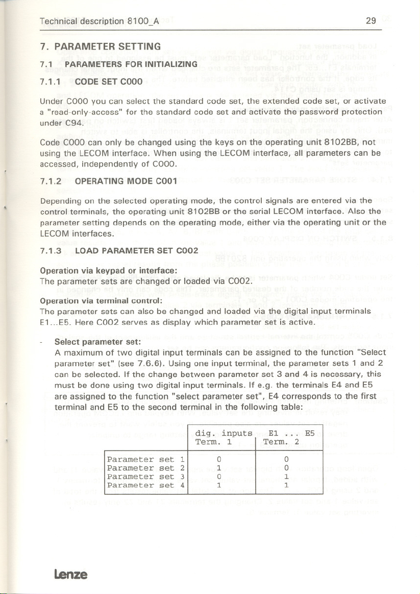
Select parameter set:
A maximum
parameter set" (see 7.6.6). Using one input terminal,the parameter sets
can be selected.Ifthe change between parameter set 3 and 4 is necessary, this
of two digitalinput terminalscan be assigned to the function "Select
1 and 2
must bedoneusing two digitalinput terminals.Ife.g.the terminals E4 and E5
are assigned to thefunction"select parameter set", E4 corresponds to the first
terminal and E5 to the second terminal in the following table:
.. . ES
El
Term.
2
0
0
Parameter set 1
Parameter set 2
Parameter set 3
dig. inputs
Term. 1
0
1
0 1
Parameter set 4 1 1
lenze
Page 32

30
load parameter set:
In addition, the function "load parameter set" must be assigned to one of the
terminals E1...E5. The parameter sets are changed when the input signal changes
its edge, if the controller has been inhibited before. The polarity of the edge
change is set using C114.
Parameter sets after mains connection:
After mains connection, parameter set 1 is always loaded first (switch-on parameter
set). Only by using the digital input terminals, the controller is able to switch
immediately to another parameter set. For this, the desired parameter set must be set
to the table above. The change is then automatie, without the function "load
parameter sets".
7.1 .4 STORE PARAMETERSET C003
Specific parameter sets must be stored permanently using C003, otherwise your
settings will be lost after mains disconnection or after changing to another parameter
set. Four complete different parameter sets can be stored.
8.1.5 SWITCH-ON DISPLAYC004
Only when using the operating unit 8201 BB.
Set under C004 which parameter is to be displayed after switching-on. For this,
enter the code number of the desired parameter. This code can only be changed in
the operating modes C001
7.1.6 CONFIGURATIONC005
= -0- or -1-.
Technical description 8100_A
Code C005 control the internal control structure and the assignment of the analog
input terminals. The following configurations can be set:
Open-Ioop control with unipolar set-value input via terminal 8 with C005
The direction of rotation is determined by terminals 21, 22.
Caution! Entering negative values for offset and amplification (see 7.2.9/7.2.10)
may result in inverting the set-value. With keypad and LECOMoperation,
negative set-values are also possible. If you safely want to prevent the
drive to reverse, change the frequency setting range to unipolar
operation using C239 = -1-.
Open-Ioop operation with bipolar set-value input via terminal 8 (set-value 1) and
with added, bipolar additional set-value (set-value 2) via the control terminals 1
and 2 using C005 = -1-. The sign of the total set-value results from the total of
set-value 1 and set-value 2. Chan ging the terminals 21 and 22 only results in
inverting set-value 1, terminal 8.
= -0-.
Lenze
Page 33

Technical description 8100_ A
Open-Ioop operation with set-value input via digital frequency input via connector
X5, tracks A, AI, B, BI (set-value 1) with C005 = -2-. The sign of the total set-
value results from the total of set-value 1 and set-value 2. Changing the terminals
21 and 22 results in inverting set-value 1. In the operating modes with keypad
and LECOMoperation, the set-value is still entered via the digital frequency input
X5.
Closed-Ioop control with bipolar set-value input via terminal 8 (set-value 1),
adding set-value 2 via terminals 1 and 2 (set-value 2) and tachometer feedback
of the actual value via terminals 3 and 4 with C005
set-value results from the total of set-value 1 and set-value 2. Changing the
terminals 21 and 22 only results in inverting set-value 1. The input voltage at the
terminals 3 and 4 has to be adapted to the tachometer voltage by means of the
switch S1 (see 4.3).
Closed-Ioop control with bipolar set-value input via terminal 8 (set-value 1),
adding set-value 2 via terminals 1 and 2 (set-value 2) and incremental encoder
feedback via X5, tracks A, AI, B, BI with C005 = 13. The sign of the total set-
value results from the total of set-value 1 and set-value 2. Changing the terminals
21 and 22 only results in inverting set-value 1. The direction of rotation of the
actual-value signal results from the phase position of the tracks A and B of the
= 11. The sign of the total
incrementalencoder (see4.4).
Closed-Ioop operation with single-track digital frequency input via X5, track 0, 01
(set-value 1), adding set-value 2 via terminals 1 and 2 (set-value 2) and
incremental encoder feedback via X5, tracks A, AI, B, BI with C005 = 16. The
sign of the total set-value results from the total of set-value 1 and set-value 2.
The sign of set-value 1 is determined by the input from terminals 21, 22. The
direction of rotation of the actual value signal results from the phase position of
the tracks A and B of the incremental encoder (see 4.4).
31
The setting of the PI controller is described under C029.
The set- and actual value inputs can be adjusted if there should be an o11set and gain
error (see 7.2.9/7.2.10). For configurations with additional set-value always check
input terminals 1 and 2.
lenze
Page 34

32 Technical description 8100_A
7.1.7 CONTROLMODEC006
Either Trip or Clamp can be selected as control modes.
In the control mode Trip, the inverter is inhibited, when 160% of the rated current is
exceeded. A fault indicationis displayed (see8). High torque can be obtained for a
short time in this mode.
In the control mode Clamp the motor current is limited to 120% of the rated current.
(Imat' S 1.2 IN)due to permanent peak current limitation. In case of shock load, the
controller will not set trip. The output signal Imax (in case of factory setting terminal
A2) is set, as soon as the peak current limitation cuts in. The red LEDflashes if the
LCD keypad 8120 is used.
Caution: If the motor is stalled, it may overheat in the control mode "Clamp".
7.1.8 LECOM1 ADDRESSC009
For the communication via the LECOM1interface, set the controller address under
code C009 (see4.5).
7.2 OPERATING PARAMETERS
7.2.1 MINIMUM FIELD FREQUENCY fdmin C010
MAXIMUMFIELD FREQUENCY fdmax C011
The set-value setting
accelerates to the minimum speed fdmin after controller enable.
is determined via fdmin and fdmax' With zero set-value the drive
fdminis only effective with analog set-value input and unipolar set-value
(C005 = -0-). fdmaxis a reference value for the setting of the acceleration and
deceleration times Tir and Tif.
With absolute set-value input, e.g. via the LECOMinterface or JOG values, fdmaxis a
limit value.
The chopper frequency of the output voltage set under C018, influences the
effective maximum field frequency. For example, the field frequency with
C018 = -0- (fCh = 1.0 kHz) is limited to 120 Hz (see 7.2.7).
Caution! fdmax is an internal scaling value. Therefore, larger changes via the
LECOMinterface, may only be done when the controlleris inhibited.
Lenze
Page 35

Technical description 8100_A
33
7.2.2 ACCLERATIONTIMETIR C012
DECELERATIONTIME TIF C013
Acceleration and deceleration refer to a change of the field frequency from zero to
fdmax.
The times Tir and Tif can be calculated as folIows:
fd 1Hz
fdmax
fd 2
fdl
.-.,," I !"'.- Tir = tir
0
Tif = tif
fdmax
Here, tir and tif are the desired times for the change between fd1 and fd2 and Tir
and Tif the values to be set under C012, C013.
7.2.3 VIf CHARACTERISTIC
A linear or square motor voltage characteristic can be set under C014. Square
characteristics are preferably used for pump and biower drives.
7.2.4 VIf NOMINALFREQUENCYfdN
The slope of the VIf characteristic is set using the VIf nominal frequency. It is
calculated from the rated motor voltage and the rated motor frequency as folio
ws:
230 V
fdN [HZ]
. fN Motor [Hz]
UN Motor [V]
The settings of the VIf nominal frequency for the most common mains and motor
combinations can be obtained from the table below. Please note that the maximum
output voltage of the inverter can only be as high as the mains supply voltage.
UNMotor fNMotor fdN
[V] [Hz] [Hz]
230 50
220
230 60 60.0
240 50
50
50.0
52.3
47.9
Lenze
Page 36

34 Technical description 8100_A
Caution! During commissioning always check that the no-load current does not
exceed the rated motor current. If necessary, the current consumption
during idle running can be reduced by increasing the VIf nominal
frequency and therefore the VIf characteristic.
7.2.5 VOLTAGEBOOST UminC016
The Umin parameter must be adapted to the asynchronous motor used, otherwise
the motor may be damaged due to overheat. We can say from experience that self-
ventilated standard asynchronous motors of insulation class Bcan be operated with
their rated current in the lower frequency range (fd=0...25Hz) for a short time.
Adapt the Uminparameter as foliows:
- Connect r.m.s current meter to one motor phase
-Run the motor without load at fd = 5Hz
- Set Umin:
a) For short-time operation in the lower frequency range, set Uminsuch that the
motor current does not exceed its rated value (lMotor:s INMotor)
b) For continuous operation in the lower frequency range, set Uminsuch that the
motor current does not exceed 80% of its rated value (lMotor :s 0,8 . IN Motor) or
use a force-ventilated motor or a motor with higher insulation class and set Umin
as under a).
An internal compensation of the DC bus voltage compensates for changes in the
mains voltage so that these must not be considered when setting the VIf rated
frequency.
7.2.6 RESPONSETHRESHOLD QMIN C017
The amin signal shows if the field frequency (in open-Ioop operation) or the actual
value of the PI-controller (in closed-Ioop operation) is smaller than or equal to the
frequency set under CO17. The amin signal can be assigned to a digital output
terminal using codes C116, C117.
Lenze
Page 37

Technical description 8100_ A
7.2.7 CHOPPING FREQUENCY FCH C018
The desired chopping frequency of the output voltage can be set under C018.
Note: The chopping frequencies limitthe effective maximum field frequency
fdmax.
35
C018 fCH
-0- 1.0 120
-1-
-2-
-3- 3.3 480
I
-4-
-5- 4.0 480
I
kHz Hz
1.5 180
2.0 240
3.6 480
eff. fdmax
.
7.2.8 RESPONSETHRESHOLD AUTO DC INJECTION BRAKING C019
DC injection braking is activated when the actual frequency is less than the
frequency set under C019. When setting 0.0 Hz, this function is not active.
The amount of the stand still voltage can be set under C036, the time of the DC
injectionbrakingcan be set under C107.
7.2.9 PRESELECTION OF ENCODER C025
Errors which may occur in the encoder or in the transmission path, can be
compensated by adjusting the set- and actual value inputs.
The analog inputs can be adjusted, if offset and gain are required.
For the pulse train/incremental encoder input X5, a gain setting is provided. For
open-Ioop operation with digital frequency input (C005
loop operation with incremental encoder feedback (C005 = -13-) the input X5 is
adjusted under C025
and incremental encoder feedback (C005
= -10-. In closed-Ioop operation with digital frequency input
= -16-) the adjustment for single-track
digital frequency input (via X5, track 0, Oll is done by C025 = -11- and the
adjustment of two-pulse incremental encoder feedback (via X5, tracks A, AI, B, BI) is
done by C025 = -10-
= -2-) and for the closed-
First select the encoder under C025, then make the adjustment under C026, C027
for the selected input.
lenze
Page 38

36
Technical description 8100_A
7.2.10 ENCODERCONSTANT C026
A constant deviation in the encoder signal (offset) can be adjusted under C026. A
gain error can be corrected under C027.
For configurations with set-value 2 (see 7.1.61. the input via terminals 1 and 2 must
always be checked.
Select the incremental encoder type for the adjustment of X5 using C026. Different
encoder constants can be adapted using C027.
For digital frequency input, make the adjustment as described under 4.4.
7.2.11 AUTOMATIC ADJUSTMENT FOR THE ACTUAL VALUE OF THE
Code C029 is used to make an automatic adjustment of the feebdback.
Preparing the adjustment:
Before adjusting the speed controller, observe the setting of the encoder constants.
ENCODERADJUSTMENT C027
PI-CONTROLLER
Analog actual value: If you use an analog tachometer signal, adjust the maximum
tachometer voltage to be expected. You can determine this tachometer voltage
fram the rated tachometer voltage and the maximum motor speed. Set the
corresponding switch combination of S1 on the contral module, as shown in
chapter 4.3.
Digital actual value: If you use an incremental encoder as actual speed detector,
select the incremental encoder input under C025 = -10- and then enter the
encoder constant under C026.
Automatic gain adjustment of actual value
Conditions:
Operate the drive in idle running.
The set-value must be at least 10% of the maximum field frequency.
Set the influence of the PI-controller under C074 to zero.
Activation of the automatic adjustment:
Select a configuration with closed-Ioop control under C005.
Enable the controller and wait for the acceleration time to elapse.
Activate the automatic adjustment with C029
adjustment by "ok". After this procedure, the gain of the actual value
feedback is set automatically.
Set the influence of the PI-controller under code C074 such that the
maximum possible slip, mostly stall slip, is compensated (e.g. 10%).
-feedback
= -1-. The inverter confirms the
lenze
Page 39

Technical description 8100_ A
Manual adjustment
If for technical reasons, automatie adjustment in no-load operation is not possible or
sufficiently precise, you can enter the adjustment factor by hand following
measurement of the variable to be controlled:
Select a configuration with closed-Ioop control under C005.
The set-value must be least 10% of the maximum field frequency.
Enable the controller and wait for the acceleration time to elapse.
Increase the influence of the PI-controller with C074 to the maximum possible
slip (stall slip, approx. 10%)
Gain (C070) and response time (C071) should be in factory-setting.
If the drive oscillates, reduce the gain (C070) until the drive runs smoothly.
Measure the motor shaft speed using a speed meter.
Calculate the value for the encoder adjustment and adjust und er C027:
37
Actual speed
Encoder adjustment (C027)
desired speed
Dynamic adjustment (C070. C071)
This adjustment is necessary following both automatie and manual adjustment. By
means of the dynamic adjustment the PI-controller is adapted to different inertias:
Increase the gain of the PI-controller with C070 until the drive starts to
oscillate. Then, reduce this value by approx. 10%
If no oscillation occurs with a gain of about 10, halve the setting time in code
C071 and repeat the gain adjustment procedure.
If the system oscillates throughout the entire range, increase the setting time
(C071) until the drive runs smoothly.
Save the settings with C003.
Additional functions
For special applications, some auxiliary functions for the PI controller can be used.
Actual speed value of the PI controller: see C051
Monitor signals of the PIcontroller: see C111
* old value C027
Lenze
Page 40

38
Technical description 8100_ A
Output actual value
Frequency pilot contral: see C238
Frequency setting range: see C239
Input integral component = 0
Using this function the integral component of the PI controller can be reset to zero.
You can activate this auxiliary function by one of the freely assignable inputs with
C113.
This function is useful, for example in applications where a drive is to be brought to
standstill with zero set-value and is to remain stationary and ready for operation
without controller inhibit. Blanking out the I-component prevents the motor from
drifting. If the drive is mechanically braked at set-value zero, blanking out the 1-
component prevents the drive from jerking when the brakes are released.
Output actual value
The digital output function actual value = 0 indicates that the drive is stationary.
The range in which the function is active is provided with a fixed window of 0.5%
referenced to fdmax.
This characteristic can be used for example in cases where the I-component has to
be blanked out.
The signal actual value
7.2.12 MASTERCURRENTC034
If the analog set-value must be entered as master current via terminal 8, adjust the
setting range under C034 as folIows:
= set-value: see C240
= 0
= 0 can be assigned to a digital output terminal using C117.
0...20mA: C034
4...20mA: C034
= -0-
= -1-
T0 change from master voltage to master current, using switch 51/4 on the control
module. For the position of the switch see 4.3.
Master voltage/potentiometer: 51/4
Master current: 51/4
Factory setting: 51/4 = OFF
= OFF
= ON
7.2.13 BRAKEVOLTAGEC036
The brake voltage is used to set the DCcomponent flowing in the motor. For
activation of the DC brake see C048 (see 7.3.7).
lenze
Page 41

Technical description 8100_ A
39
7.2.14
The JOG frequency set-va lues are set using the codes C038 and C039. First, enter
PRESELECTION OF JOG REFERENCEC038
REFERENCE39
the JOG set-value under C038. This JOG set-value can be assigned a frequency
under C039. If e.g. -2- has been selected under C038, you can enter the frequency
for JOG 2 under C039.
JOG set-values which are larger than fdmax are limited internally to fdmax'
To activate the JOG set-values see 7.3.5. For activated JOG set-value, set-value 2 is
switched
7.3 CONTROL PARAMETERS
off.
Depending on the operating mode C001 (see 7.1.2). the control parameters are
changed via the control terminals, the operating unit 810288 or via the LECOM
interface.Forterminalcontrol, the followingcodes serve as displays. If keypad or
LECOMcontrol is selected, the codes serve as operating parameters.
7.3.1 CONTROLLER ENABLE C040
Controller enable
Independently of the operating mode C001, the controller must be enabled by
applyinga voltage between 13 and 30 V across terminal28. When using the
operating unit 810288, the controller can always be inhibited using the STP key and
be enabled by pressing SH + STP.
Inthe operating mode
and enabled additionally using
LECOM operation (C001 = -3-). the controller can be inhibited
C040 = -1- (via the LECOM interface)
The controller can only be enabled via those input channels, which were used to
inhibit the controller:
- Terminal 28
-CodeC040 (inthe operating modes keypad and LECOMoperation)
- Stop key
-Trip fault indication
If, for example, the controller has been inhibited
it can only be enabled via C040 = -1-.
Controller enable after mains connection
The controller is enabled after mains connection,
across terminal 28.
enabled. in addition
Only in the operating mode C001 = -3-, the controller must be
via LECOM interface (C040 = -1-).
in LECOM operation via C040 = -0-,
if a voltage of 13 ... 30 V is applied
lenze
Page 42

40
Controller enable after chan ging the operating mode C001
The operating mode can only be changed if the controller is inhibited first. The
controller can only be enabled by the input channel, which has been used to inhibit
the controller.
Controller enable when chan ging the parameter sets C002
Before changing the parameter sets, the controller must be inhibited. Loading another
parameter set causes the controller to be initialized again. It then acts as after mains
connection.
Caution! When changing the parameter sets or loading factory setting, the drive
may accelerate if it has not been inhibited via terminal 28 first.
Technical description 8100_ A
7.3.2 INVERTSET-VALUEC041
Codes C041 and C042 are provided for the functions:
Depending on the operating mode C001, the codes have a direct effect on the
functions or display the state of the control terminals 21 and 22. Also, in case of
terminal control, the function of the terminals 21 and 22 can be changed using C176
(see 7.6.191.
Quick stop function
By activating quick stop, the drive is decelerated along the pre-set deceleration ramp
with C105. When reaching fd
Uminset with C016
In addition. a DC brake can be activated via C019 using a holding time to be set with
C107. After the holding time, the inverter changes its output voltage to OV.
Keypad
For keypad or LECOM operation (C001 = -1-, -3-1. the set-value is inverted with
C041 and quick stop is activated with C042. The terminals 21 and 22 are always
active in these operating modes.
QUICKSTOPC042
Invert set-value and
Activate quick stop
=0 Hz, the output voltage corresponds to the value
(see 7.2.51.
or LECOM operation:
lenze
Page 43

Technical description 8100_Ä
Terminal control:
With terminal contral (C001 = -0-, -2-) the momentary state of the terminals 21 and
22 according to the terminal configuration C176 is detected and displayed in C041
and C042.
Terminals functions with C176=-0-
term. 21
term. 22
High
Low
Low Low . x -
Disp. CD41
Low
High
Disp. C042
- 0 -
- ,- . 0 - Set-value inverted
Meanin9
. D - Set-value not inverted
.1.
Quick stop active
41
If a voltage between 13 and 30V (High signal) is applied across terminals 21 and 22
both, the direction of rotation is provided by the terminal signal, which was active
first. If a HIGHsignal is applied to both terminals before mains connection, the
controller activates "quick stop".
Terminal function with C176
term. 21 term. 22
High
Low Low
Low . 0 - - x - Set-vaLue not inverted
x
High
x Low - x .
=-,-
. 0 -
Meaning
Quick stop active
Quick stop not active
Disp. C041 Disp. C042
- 1 - - x . Set-value inverted
- x - - 1.
Warningl With C176 = -1- in case of wire breakage at terminal 21, the drive may
change its direction of rotation.
7.3.3 TRIP RESETWITH LECOMC043
Code C043 is used to reset a fault. For this, enter C043 = -0-.
Code C043 can only be reached via the LECOMinterface.
7.3.4 PROCESS CONTROLC044
Inthe operating modes keypad or LECOMoperation, the process is switched on or
off using C044. In case of terminal control, the process control can be assigned to
one of the digital inputs E1...E5. Here C044 is used to display whether the process
contral is active.
iBnze
Page 44

42
The process control sequence determines the main set-value and the Ti time of the
corresponding ramp function generator in a sequence and time which can be
programmed. The process control comprises a maximum of eight steps. Each step
can be assigned the following parameters (see 7.6.20):
- one frequency set-value (using C211)
- one pair of acceleration and deceleration times (using C212)
- the duration (using C213)
Technical description 8100_A
-the following step (using C214)
If the process control is activated, each step which has been reached is displayed
under C160. Each step can also be output as a signal via one of the freely
programmable digital output terminals using C117.
The process control is interrupted and reset on step 1 by one of the following
actions:
-controller inhibit
- quick stop
- trip fault indication
After having cancelled the interruption, the controller starts with step 1, unless the
process control is inhibited first. Over- or undervoltage indications do not influence
the process contro!.
Functions, which may influence the main reference, such as
-invert set-value
- ramp function generator input
- ramp function generator stop
- DC injection braking
are available during the process contro!. For example, the time of the momentary
step continues while the DC brake is activated. During the process control, set-value
(C049) is set to zero. The deceleration time set under C221 remains active.
7.3.5 ENABLEJOG SET-VALUEC045
Terminal control:
According to the assignment of the JOG set-values to the digital input terminals, the
JOG enable results from the binary coding of the input terminals (see 7.6.6).
This function can be assigned to a maximum of four digital inputs. Therefore, 1, 3, 7
or 15 binary coded JOG-set-values are possible when assigned.
= zero
lenze
Page 45

T echnical description 8100_ A
If, for example, the terminals E1, E3, E4 and E5 are assigned for the JOG enable, E1
corresponds to the first terminal, E3 to the second terminal, E4 to the third terminal
and E5 to the forth terminal in the following table:
43
digital input terminals
1st term. 2nd term.
Set-value 1
JOG 1
JOG 2 active
In case of operation via keypad or LECOM interface, activate the desired JOG set-
value using C045.
active
...
JOG 15 active 1
0 0
1 0 0 0
0
1 0
1 1
EI ... ES
3rd term. 4th term.
0 0
0
1
7.3.6 SET-VALUE1 C046
Code C046 shows the momentary set-value 1. In case of operation via keypad or
LECOM interface, set the set-value using C046.
The input or display can be relative in %fdmax or absolute in Hz. You can change
between these two modes using C 172.
7.3.7 DC BRAKINGC048
The DC injection braking is activated as folio ws:
incase of terminal control via the digitalinput terminals (toassign the function to
one of the digitalinput terminals
braking active or not active.
of operation via keypad 8102BB or LECOMinterface (see 7.1.2) using
incase
see 7.6.6). C048 shows here: DC injection
C048 = -1-
automatically,ifthe fieldfrequency fallsbelow the Auto DC treshold
(see 7.2.8) (no display in C048).
The amount of the holding voltage
is set with C036 (see 7.2.13) and the time of
activation with C107 (see 7.6.3).
Caution! Long-term operation of the DC brake may result in overheating the
motor.
Lenze
Page 46

44
7.4 DISPLAY PARAMETERS
Display parameters can only be read.
7.4.1 DISPLAYSET-VALUE2 C049
C049 shows the momentary set-value 2 (in % fdmax). Independently of the
operating mode. set-value 2 is always provided via the control terminals 1, 2, and
not via the LECOMinterface or the keypad 810288.
With suitable configuration (see 7.1.6) set-value 2 is added internally to set-value 1
(C046). The total is limited internally to :I::fdmax'
7.4.2 OUTPUT FREQUENCYC050
C050 shows the actual running frequency in Hz.
7.4.3 ACTUALVALUEOF PI-CONTROLLER
Code C051 shows the actual value of the PI-controller. Depending on the display of
set-value 1 (C046). you can select with C172 a scaled display (in % fdmax)or an
absolute display (in Hz).
In open-Ioop control, "0" is shown with C051.
7.4.4 MOTORVOLTAGEC052
C052 shows the actual output voltage and therefore the motor voltage in Volts.
Technical description 8100_A
Caution! Even when the display shows "OV". the motor terminals may carry
voltage. 8efore working on the motor side. always disconnect the
controller from mains and wait at least 30 seconds.
7.4.5 DC BUSVOLTAGEC053
CO53 shows the actual DC bus voltage in Volts.
7.4.6 TRIP FAULT INDICATIONC0067
Code C067 displays a momentary fault (see 8). The fault can also be reset under this
code.
Reset faults are saved in the history butter and can be read using the LECOM
interface with codes C161 to C168. When using the operating unit 810288. they
can be displayed by pressing the . key. A maximum of eight fault indications can
be read; the last fault is displayed first. then the one before and so on.
Lenze
Page 47

Technicaldescription8100_A
7.5 GENERALPARAMETERS
45
7.5.1 OPERATINGSTATUSC068
CONTROLLERSTATUSC069
The codes C068 and C069 contain information about the controller and operating
status. They can only be read via the LECOM interface.
C068 Display of the operating status
Bit no.
Signal
Bit no. 7 4
15
TRIP
Signal
*)
Bit no. 14: nset = nactual
C069 Display of the controller status
Bit no.
Signal
Bit 6 is not used.
Further information can be obtained from the technical description "LECOM AlB".
7 6 5 4 3
RFR
14 13
*)
IMAX
Communication fault
xxxx RESET
12 11
QSP
IMP
3
10
R/L
Operating fault
2 1
AUTO REMOT PCHG CALARM
9 8
QMIN
RFR
o
BALARM
7.5.2 GAINOFPICONTROLLERC070
RESPONSETIMEOFPI CONTROLLERC071
INFLUENCEOFPI CONTROLLERC074
0
With codes C070. C071 and C074 the PI-controller is adjusted. The procedure for
this is described in 7.2.11.
7.5.3 RATEDMOTORPOWERC081
The power of the connected motor can be set with C081. This setting is required. to
adapt the smooth running of the motor with low field frequencies.
7.5.4 CONTROLLERTYPEC093
With C093. the controller type 810x is displayed. Code C093 can only be read via
the LECOM interface.
ienze
Page 48

46 Technical description 8100_ A
7.5.5 USER PASSWORD C094
If a password is entered with C094, the code set under COOO(see 7.1.11 can only
be changed if the password has been entered.
If you do not need a password, enter C094 = -0-.
7.5.6 LANGUAGEC09S
With code C098 you can enter the language of the display texts on the option al
operating unit 810288. German, English, and French language are possible.
7.5.7 SOFTWAREVERSIONC099
C099 shows the software version.
7.6 APPLlCATION PARAMETERS
7.6.1 PRESELECTION ADDITIONAL RAMP TIME C100
Apart from the acceleration and deceleration times set under C012 and C013, 15
ADDITIONAL ACCELERATION TIME C101
ADDITIONAL DECELERATION TIME C103
additionalvalues can be programmedfor the main set-value (seesignal flow chartl.
First, preselect the desired pair of ramp times using C100, then enter the value for
the additional acceleration time using C101 or the additional deceleration time using
C103.
If, e.g. -2- has been selected in C102, enter the value for the additional deceleration
time Tif2 in C103.
The additional acceleration and deceleration times refer to a change of the field
frequency from 0 to fdmax and can be calculated as described under 7.2.2.
To activate the additional acceleration and deceleration times see
7.6.2 DECELERATIONTIME FORQUICKSTOPC105
If the quick stop function (see 7.3.21 is activated, the drive is decelerated with a
special deceleration time. This deceleration time must be set using C105.
7.6.12.
lenze
Page 49

Technical description 8100_A
7.6.3 HOLDING TIME FOR DC INJECTION BRAKING C107
The time of the OC injection braking can be set using C107. When setting 999s
under C107, the holding time is not limited. After the holding time, the inverter
switches its output voltage to OV.
To activate the OC brake see 7.3.7.
47
Caution! Long-term operation of the OC brake may result in overheating the
motor.
7.6.4 AMPLlFICATION
OFFSET OF MONITOR OUTPUT C109
OF MONITOR OUTPUT C108
To adapt analog output signals, e.g. to extern al displays, C108 and C109 are used to
set the amplificationand otfset of the monitor output terminal 62.
These settings remain active when the function of the monitor output is changed.
7.6.5 MONITOR SIGNAL C111
The monitor output terminal 62 can be assigned to the signals which are selected
under C111 and can be operated as voltage output (:t 10V) or as current output
(:t 20mA). The function is changed by 52 on the control mode (see 4.3).
The following scaling of the output signals is factory-set:
for frequencies: +fdmax corresponds to VMonitor
-fdmax corresponds to VMonitor
for voltages:
1000 V corresponds to VMonitor
o V corresponds to VMonitor
To adapt the display element, otfset and gain can be adjusted. (see 7.6.4).
+ 10V/+20mA
-10V/-20mA
+ 10V/+20mA
+ OV/+OmA
Lenze
Page 50

48 Technical description 8100_A
7.6.6 PRESELECTION OF FREELY PROGRAMMABLE DIGITAL INPUT C112
The digital inputs E1 to E5 can be assigned to the various functions to be selected in
C113. For this, first select the input to be assigned using code C112. Iffor example
the digital input E2 is preselected with C112 = -2-, the function "Trip-Set" can be
assigned to the terminal using C113
Allfunctions can only be assigned once. To activate the JOG references and the
additional Ti times, up to four terminals can be used. In addition, the polarity and the
priority can be changed using C114 and C115
7.6.7 POLARITYOF DIGITALINPUT
Using
inputs E1 to E5.
C115 is used to determine whether the preselected input terminal with its function is
always active or, is switched off depending on the operating mode (see 7.1.1 I. If a
digital input terminal
the terminal terminal signal overwrites an information entered via the keypad or the
LECOMinterface.
Caution: The settings of polarity and priority refer to the selected signal. They are
FUNCTION OF FREELY PROGRAMMABLE DIGITAL INPUT C113
= -4-.
(see 7.6.71.
PRIORITYOF DIGITALINPUT
C114, you can choose whether HIGHor LOWsignalsare active for the digital
is assigned a priority (terminal always activel with C115 = -1-,
lost when the function of the terminalis changed, i.e. with every new
assignment the factory settings are activated.
The factory setting of the polarity for "Trip-Set" (C113 = -4-1is not safe against
wire breakage.
lenze
Page 51

Technical description 8100_A
49
7.6.8 PRESELECTION OF FREELY PROGRAMMABLE DIGITAL OUTPUT C116
The digital outputs Al to A4 and the relay output can be assigned with the functions
which are selected under Cl17. For this, first select the output to be assigned using
Cl16. If for example the digital output A2 is selected with Cl16
assign the indication "healthy" to the terminal using Cl17 = -4-.
Everyfunction can only be assigned once. The relay output terminals Kll, K14 can
be assigned like the digital output terminals Al to A4.
Inaddition, the assigned function can be changed in its polariy using Cl18.
With its factory setting, the digital output terminal A4 is assigned to the signal 6*fd.
Ifyou want to use A4 as a digital output, switch 52 on the control module must be
set to "A". In this case, the default setting for A4 is "Actual value = 0".
FUNCTION OF FREELY PROGRAMMABLE DIGITAL OUTPUT C117
= -2-, you can
Lenze
Page 52

50 Technical description 8100_A
7.6.9 POLARITYOF DIGITALOUTPUTC118
The functions assigned to the digital outputs A1 to A4 can change between HIGH
active and LOW active.
Caution: The setting of the polarity refers to the selected signal. It is lost when
the function of the terminal is changed, i.e. with every new assignment,
the factory-setting is activated.
7.6.10
The surveillance functions "external fault" and "PTC motor protection fault" can be
activated or deactivated using C120. In addition, you may select between a warning
or a trip indication, in case a fault should occur (see 7.4.5). For this, first enter the
desired surveillance function with C119 and then enter the function with C120.
For example, the surveillance function "external fault" is entered with C119 = -0-,
then it is activated with C120
A warning is automatically displayed, just like a Trip fault. Unlike a Trip fault, the
displays (operating state display and plain text display of the operating unit 810288)
are not flashing during a warning. During a warning, the signal "healthy" (RDY)is
reset, but the operation of the frequency inverter is not interrupted. The warning is
confirmed just like a Trip fault and is stored in the history butter.
7.6.11 BAUD
The baud rate is selected with C125.
7.6.12
Terminal control:
The enable of the additional Ti times results from the binary coding of the input
terminals used for this function.
A maximum of 4 digital inputs can be assigned to the function "enable of Ti times"
This means that 1, 3, 7 or 15 addtional Ti times can be used.
The Ti times refer to fdmax and can be calculated as described under 7.2.2.
PRESELECTION OF SURVEILLANCE C119
SURVEILLANCE FUNCTION C120
= -2-as warning.
RATE C125
ENABLE ADDITIONAL TI-TIM ES C130
.
lenze
Page 53

T echnical description 8100_ A
If, for example, the terminals E1, E3, E4 and E5 are assigned for the Ti enable, E1
corresponds to the first terminal, E3 to the second terminal, E4 for the third terminal
and E5 to the forth terminal in the following table:
digital input terminals EI to ES
1st term. 2nd term. 3rd term. 4th term.
ITir(C012), Tif(C013)
Tir1, Tifl active
Tir2, Tif2 active
...
Tir1S, TiflS active
For operation via the operating unit or the LECOM interface, you can enter the
desiredpairof ramp times with C130.
0
1
0 1 0 0
1 1 1 1
0
0 0 0
0
0
7.6.13 RAMP FUNCTION GENERATOR STOP C131
This function stops the ramp function generator for set-value 1.
The additional deceleration time for quick stop and the additional set-value are not
affected.
Incaseofterminalcontral,C131 shows the state of the digitalinput. In case of
operation via the operating unit 8102BB er the LECOMinterface, the ramp function
generator is stopped with C131
.
7.6.14 RAMP FUNCTION GENERATOR INPUT = ZERO C132
51
This function resets the ramp function generator for set-value 1. The drivethen
decelerates with the activated deceleration to zero.
For terminal control, C132 shows if the function "ramp function generator input =
zero" is active or not.Incase ofoperation via the operating unit 8102BB or LECOM
interface, the ramp function generator is set to zero with C132
= -1-.
7.6.15 CHARACTERISTIC OF RAMP FUNCTION GENERATOR C134
The ramp function generator characteristic -linear or S-shaped- is selected using
C134.
An S-shaped characteristic enables a jerk-free acceleration for short Ti times. The S-
shape is not maintained if the set-value (C046) is changed during the
acceleration/deceleration and does not refer to the additional set-value.
7.6.16 THRESHOLD FOR CHOPPING FREQUENCY REDUCTION TO 1 KHZ C 143
Thebestsmooth running with low speeds is obtained with a chopping frequency of
1 kHz. WithC143, you can enter the field frequency, below which the chopping
frequency is reduced automatically to this value.
Lenze
Page 54

52
Technical description 8100_ A
7.6.17
If the process control has been activated, C160 is used to display the step which has
been reached.
C160 = -0- is displayed.
DISPLAY OF PROCESS CONTROL STEP C160
If the process control is not activated (C044 = -0-) or finished,
7.6.18 REFERENCEINPUT C172
The display
%fdmax)
or input of the set-value 1 depends on C172, either relative to fdmax (in
or absolute as frequency (in Hz).
7.6.19 FUNCTIONOF TERMINALS21,22 C176
The function of the control terminals 21, 22 depends on C176, either:
term. 21: Deactivate quick stop, do not invert set-value
term. 22: Deactivate quick stop, invert set-value
or: term. 21: Invert set-value
term. 22: Deactivate quick stop
7.6.20
To set a process contral (seeC044), one frequency set-value, one pair of
acceleration and deceleration times, the duration and the next step can be assigned
to each process control step.
First
parameters can be assigned:
PRESELECTlON OF PROCESS CONTROL STEP C210
SET-VALUE C211
TI TIME C212
DURATION C213
NEXTSTEP C214
preselect the desired process control step using C210, then the required
1) Set the frequency set-value which is valid for this step using C211. For this, set-
value 1 (C046) and 15 JOG set-values are available.
2) Set the corresponding pair of acceleration and deceleration times using C212.
Apart from the standard Ti times, C012/C013, you can select one of the 15
additional Ti times.
3) Set the duration of the preselected step using C213.
4) Set the next step using C214. After the process control has been activated, it
always
are also possible. When entering C214 = -0-, the process control is finished, i.e.
starts with step 1. You can enter any step as the next step so that loops
the set-value and the Ti times are controlled like before activating the process
control.
Lenze
Page 55

Technical description 81 00_ A
53
7.6.21
ACCELERATlON TIME FOR SET-VALUE 2 C220
DECELERATION TIME FOR SET-VALUE 2 C221
Theacceleration and deceleration times for reference 2 (see 7.1.6) is set separately
usingC220, C221.
TheTi times refer to fdmax and can be calculated as described under 7.2.2.
7.6.22
LOAD CHANGE ATTENUATlON C 234
Whenoperating with changing loads, where energy is repeatedly fed back into the
DCbus of the inverter (e.g. with eccentric loads), the rise of the DC bus voltage is
limited.The fed back energy is reduced so that the use of a brake chopper may not
be necessary. The suppression of the load change oscillations is set using C234.
7.6.23 FREQUENCY PILOT CONTROL C 238
Forclosed-Ioopcontrol,it is useful to keep the influenceof the PI-controllerlow. In
suchapplications,the output frequency can be pilot-controlledwith the total set-
value. (C238 = -1-). In this way the deviation in open-Ioop control is already very
low and can be compensated by the PI-controller. The greater the system deviation,
the higher the influence of the PI-controller (C074) must be set. This results in Ionger
response times.
Withclosed-Ioop control it may be necessary for the influence to be up to 100%. In
such cases, pilot control is generally not required
(C238 = -0-).
Pilotcontrol of the output frequency using the actual value (C238 = -2-)can be
used in the case of particularly highly dynamic drive requirements, e.g. for the
positioning of traversing drives. The output frequency is then pilot-controlled in line
with the speed and the PI-controller generates the necessary slip to attain the set-
value. Therefore the drive remains stable even with extremely short set-value
changes.
7.6.24
Frequency setting range
C 239
If workingwithclosed-Ioopcontrolled configurations or with a second set-value in
open-Ioop operation, it is conceivable that situations may arise in which the direction
of motorrotation reverses. In pratice, this may not be desired. Withcode
C239 = -1-, you can ensure that the drive is not able to reverse its direction of
rotation.
Lenze
Page 56

54
Technical description 8100_A
7.6.25 WINDOW FOR DIGITALOUTPUTACTUALVALUE
In closed-Ioop operation, the functions "actual value = set-value" indicates that the
system deviation (difference between set-value and actual value) is within a certain
specified range. The display range is designed as a window, which is positioned
above and below the switching threshold. The width of this window can be specified
using C240. The value is referenced to fdmax(C011) and operates with a hysteresis
of 0.4%.
In open-Ioop operation, the function "actual value = set-value" is mapped to the
signal "ramp function generator input = output". The signal actual value
can be assigned to one of the digital output terminals.
7.6.26 WINDOW FOR DIGITAL OUTPUT "RAMP GENERATOR
As soon as the actual field frequency has reached the set frequency, the signal
"ramp function generator input = output" is activated. For this, enter the size of a
target window in per cent of the set-value with C241. The signal operates with a
hysteresis of 0.4%.
The signal ramp function generator input
digital output terminals with C117.
7.6.27 LECOM1
Codes up to C255 can be processed with version 1.0 of the LECOMAlB protocol. To
be able to reach codes of higher numbers with this version, the access range can be
switched with code C249. Code C249 exists in all code ranges.
INPUT = OUTPUT C241
= output can be assigned to one of the
-CODE BANKC249
= SET-VALUEC240
= set-value
Further information about serial communication with the standard interface LECOM 1
(LECOMAlB) is contained in the LECOMAlB technical description, which we would
be pleased to send on request.
lenze
Page 57

Technical description 8100_A
55
7.6.28 SET-VALUE1 (PROCESS DATUM)C380
With codes C380 to C382 it is possible to enter and read highly accurate set-values
and actual values with aresolution of 14 bits and corresponding sign via the
LECOM1interface.
C3BO
Set-value 1 scaled to the maximum field frequency fdmax' with numerical value 214
corresponding to 100% fdmax. The information corresponds to that in C046 with the
difference that in this case you can read the controller value directly, thus excluding
the possibility of any conversion error.
C3B1 Total set-value:
Total of set-value 1 and set-value 2, each downstream of the ramp function
generator, scaled to fdmax.In closed-Ioop control, the total set-value corresponds to
the PI-controller set-value. The information corresponds to that in CO50 with the
difference that in this case you can read the controller value directly, thus excluding
the possibility of any conversion error.
Code C381 can only be read.
C382 Actual value of PI-controller:
Actual value for the PI-controller, scaled to fdmax' with numerical value 214
corresponding to 100% fdmax.The information corresponds to that in C051 with the
difference that in this case you can read the controller value directly, thus excluding
the possibility of any conversion error.
TOTALSET-VALUE(PROCESSDATUM)C381
ACTUALVALUEOF PI-CONTROLLER(PROCESS DATUM)C382
Set-value1:
Lenze
Page 58

56
8. CODETABLE
Code 1 1
COOOCode .et
C001 Oper.tlng _
C002 Load por t.r .et
COO3Store per ter .et I -1- SK+ PRG P.r_ter .et 1
PRG
INITIALlZIIIG
CodeCOOcan only ba cII_od uslng th. keya of
the optl 1 _r.tlng ...It .10288 end not
vi. Int.rf.c.. Whan. peuword I. cleflned .....
C94, you can only change bat -0- end -1- or
.0- end -2- If you ent.r th. pe rd (+PW).Aft.r
conflralng th. cII_e wlth SK+ PRG,enter th.
po rd ualng the. or ~ key end finish the
entry wUh SK+ PRG.
.. .........
-0- SK + PRG (+PW) Standard code set reod only I -1-
-1- SK+ PRG (+PW) Standard code .et
-2- SK + PRG (+PW) Extended code s.t
-9-
P.ss rd hurt (+PW)
XXX SK + PRG Enter po..word .ccordlng to C094
Th. _r.tlng _ canbech_ed vi. the keyaof
the _r.ting ...It 810288end vi. the LECOI
interface.
Th. f...ctlons "controller enable" end "quick .top"
can be controlled vi. teralnsl., Independently
of the _r.tlng mode.The .ame .pplles to ter-
.insl f...ctlons wlth .ssl;ned prlorlty (C115).
-0- SK + PRG Control: Teralnsl.
-1- SK+ PRG Control: Keys
--- - -------------- ------ ----- ---
-2- SK + PRG Control: Teralnsl.
--- - --- - --- - --- - --- - - --- - --- --- - --- - - - ---- - - - --- -- ---
-3- SK+ PRG Control: LECOI Interflce (X6)
------ ---- - --- ---- ----- - ---- --- - - - ------
-0- SK+ PRG F.ctory setting
---------------------------------------------------------
-1- SK+ PRG P.rameter set ,
---------------------------------------------------------
-2- SK + PRG P.r ter .et 2
- - ------ -------
-3- SK+ PRG P.r_ter set 3
-- - - --- - ---- - --- - - --- -- -- - - --- - --- - - - - -- -- - -- - --- - ---
-4- SK + PRG P.r ter s.t 4
---------------------------------------------------------
P.r... .ettlng: Keys
P.r... setting: Keys
P.r_. setting: LECOI Interf.ce (X6)
P.r s.ttlng: LECOM Interface (X6)
only pos.lble when inverter Is Inhlbited
only pos.lble when InverterI. tnhlbUed
--- ---- ----------- ---- --.
-2- SK+ PRG P.r_ter .et 2
---------------------------------------------------------
-3- SK + PRG P.r ter s.t 3
----- ----- ---- ----- ---- ----- ---- ------ --.--
-4- SK+ PRG P.r_ter set 4
- ---------------------- --....
P.r ter set 1 Is looded .ut tlc.lly .fter
.wltchlng on.
8100_ A Technical description
......--....--
---"' -..-..................
--......
only for ..rvlce
---........
-- -- ---......--
--- --------------
custOlMtr
F8Ctory
I
HttlngS .ettlng.
-0-
-,-
-1-
lenze
Page 59

8100_A Technical description
57
Code level Factory
C004 Switch-on display
<===>
xxx SM+ PRG Code nurber for display after
---------.......-..--....----------....-----.------..-----------
only for optional operating unit 8102BB
* C005 Configuration
Cautionlll When the 'configuration is changed, con- I -0-
tral structure end terminal assignnent are. changed.
Change only possibl. when controller is inhibitedl
------------------------------------------....-------------
-0- SH+ PRG .Open-Löop control, unipolar
Set-value: analog via term. 8
Direc. of rot'.: digital via terminals 21, 22
-----....--------------------......---------.---..-......----------
-1- SH + PRG Open-loop control, bipolar set-value
Set-value: analog vi a term. 8
Oirec. of rot.: digital via term. 21, 22
set-value 2: analog via term. 1, 2
....--.------.--..---..-..--..---------..--...-.---.-----
-2- SN + PRG Open-loop control whh pulse train
Set-value: Pulse train, two tracks via X5
Direc. of rot.: digital via term. 21, 22
Set-value 2: analog via term. 1, 2
------..---------.-.--..--.-------..-....--.-------------
-11-
Set-value 1: analog via term. 8
Direc. of rotw: digital via term. 21, 22
Set.value 2: analog via term. 1, 2
Actual value: analog via term. 3, 4
.---.------------.--..--...-...------.--..---...--.---_.-
.13- SN+ PRG Closed.loop control with incremental
Set.value 1: analog via term. 8
Direc. of _rot~_; digital via term. 21, 22
Set-value 2: analog via tenn. 1, 2
Actual value: incremental encoder, 2 tracks via XS
-----...--.--------...---.--...--.---.--.------.....----.
Parameter levelPRG
swhching.on
(set-value 1) and additi onal set-value
(set-value 2)
and sign of set-value
camot be changed to i_nput via interface
or 810288
(set-value 1) and additional set-value
(set-value 2)
camot be changed to input via interface
or 810288
and phase position of pulse train tracks
cannot be changed to input vi a interface
or 8102BB
SH+ PRG Closed-loop control with analog feedback
can be changed to input via interface
or 8102BB
and sign of the set.value
camot be changed to input via interface
or 8102BB
with evaluation of the sign for the
direction of rotation
encoder feedback
can be changed to input via interface
or 81028B
and sign of the set-value
can be changed to input via interface
or 810288
cannat be changed to input via interface
or 8102BB
(tracks A, AI, B, 81)
detection of the direction of rotation
via phase position of the tracks
sett; ngs sett ings
Customer
I
50
Lenze
Page 60

58
8100_A Technical description
Code level PRG Parameter level Factory Customer
C006 Control mode -0- SH + PRG Trip -1-
. C009LECOMI- xx SH+ PRG 1.. .99 1
controller address --- ------. ... - --- --.. ..- ---- --- ---- - --- ...
C010 mini fjeld xxx Hz 0.0.. .480Hz 0,0.. .100Hz {O,IHz} O.OHz
frequency fchin 100.. .480Hz {1Hz}
C011 maxi field xxx Hz 7.5...480Hz 7.5...100Hz {O,IHz} 50.0Hz
frequency fdnax 100. ..480Hz {1Hz}
<===> settings settings
-16- SH + PRG Closed-loop cantral with pulse train
Set-value 1: pulse train single-track via X5
Oirec. of rot.: digital via term. 21, 22
Set-value 2: analog via term. 1, 2
ActuaL value: incremental encoder , 2 tracks via X5
---------------------------------------------------------
.1- SH + PRG Clan.,
-------------.-.-.-.-------------------------------------
Change only possible when controller inhibited!
Thecontroller address canonly be changedin the
operating modes C001 = -0. and-1-.
Controller adckess for conrrunicationvia LECOM1
"xO" is not possible; X is a group adckess
OPERATINGPARAMETERS
fanin is only effective in case of analog set.value
in configuration COOS= .0-.
-----------.......------.......-------...................-
Caution!!, In case of parameter setting via inter-
face, corrprehensive changes nust be in one step
only while the controller is inhibited.
set-value via X5 (tracks 0, 01) and
incremental encoder feedback via XS
(tracks A, AI, B, BI)
(track 0, on
can be changedto input via interface
or 810288
cannot be changedto input via interface
or 8102BB
(tracks A, AI, B, Bn
detection of the direction of rotation
via phase position of the tracks
C012 (~~~e~:~~~~~~eTi~ xxx s 0.0...990s O.~::::~s {~~=~ 5.0s
C013 Oeceleration T"f xxx s 0.0...990s 100...99Os <lOs} 5.0s
(for set-value h ... u_ u u u uu _uu _u uu_
C014VIf characteristic -0- SH+ PRGlinear characteristic U - fd -0-
C015 Vif rated frequency xxx Hz 7.5...960Hz 7.5...100Hz {O.IHz} 50.0Hz
fdN 100.. .960Hz <1Hz)
C016 Voltage boost xxx % 0.0.. .40% {O.I%} 0.0%
Umin
.C017 Threshold xxx Hz 0.0. ..480Hz 0,0. ..100Hz {O,IHz} 2.0Hz
Qmin 100.. .480Hz <1Hz}
Acceleration and deceleration times refer to a
frequency change of OHzto the maxinunfield
frequency set under fdnax
--.----.........------.......----............------......
-1. SH + PRG square characteristic U - fd2
----------............---.....----.--.--..........---....
Change only possible when controller inhibited!
-----------........------......----------.......------...
Open-loop control:
If the output frequency faLLs below this threshold,
the Qminsignal is set.
Closed.loop control:
If the Bctual value of the PI.controller falls
beloN this threshold, the Qmin signal is set.
10...100s <ls}
lenze
Page 61

8100_A Technical description
59
Code 1eve 1 Factory
.C018 Chopper frequency
fch
.C019 Threshold of
automatic
DCbrake
C025Preselection:
Encoder
<===>
-------------------....----------------------------------
-0- SH+ PRG
---------------------------------------------------------
-1- SH+ PRG 1500 Hz
------------------------------------------------------.--
-2- SH + PRG
- - -- - - -- - --- - -- -- ---- -- -- -- - -- ---- --- -.-- --- --- ~~~~~-- ---
-3- SH + PRG 3300 Hz
~- - - - - - - - - - - - - - - - ~- - ~- - - - - - - - - - - - - - - - - - - - - - - - - - - - - - - - - - --
-4- SH+ PRG
. - - - - - - - - - - - - - - - - - - - - - - - - - - - - - - - - - - - - - - - - - - - - ~ - - - - - - -. - --
-5- SH + PRG
--- - ------- ~--~---- .-- - --- --~--~-- ----- ----~ --- --
xxx Hz 0.. .480Hz 0.0.. .100Hz (O,IHz) I O.OHz
~ - - - - - - - - - - - - - - - - - - - - - - - - -. - - - - - - - - - - - - - - - - - - - - - - - - - - - - --
-1- SH + PRG Analog input term. I, 2 I -4-
- - - - - - - - - - - - - - - - - - - - - - - - - - - - - - - - - - ~- - -. - -. - - - - - - ~ - - - - - - --
-4- SH+ PRG Actual value input term. 3, 4
---------------------------------------------------------
-10- SH + PRG Pulse train/lncremental encoder input X5
---------------------------------------------------------
-11- SH+ PRG Pulse train input XS
C026 Constant for [C02S1
C027 Setting for [C02S1
1 1_________.___________
---------------------------------------------------------
xxxx -1000 ... +100OmVOffset correct;on
------------------------------------------------.--------
-1- SH + PRG
---------------.--------------------------------.--------
-2- SH + PRG 1024 pulses/Hz or increments/rev.
---------------------------------------------------------
-3- SH + PRG 2048 pulses/Hz or increments/rev.
---------------------------------------------------------
-4- SH + PRG 4096 pulses/Hz or increments/rev.
1 1_________.___________
. - - - - - - - - - - - - - -.. - - - - - - - - - - - - - - - - -. - - - - - - - - - - - - - - ~- - - - - --
XXXX -2.500 ... +2.500 Signal """lification
---.----------------.--------------.--.-.----------------
XXXX -5,000 ... +5,000 Signal """I if;cat;on
-----......-------------..--.--------------.---.---------
----------.---.-.-.-.-----------.------------------.--.-.
Parameter levelPRG
1000 Hz
2000 Hz
3600 Hz
4000 Hz
Change is only possible when controller inhibitedl
Withthe setting 0.0 Hz the automaticactivation
of the DCbrake is switched off.
First, select the input to be adjusted via C02S.
Then, adjust the inputs us;ng C026 and C027.
Set-value 2 when COOS=-1- ... -16-
100.. .480Hz (1Hz)
Actual value wit e005 = -11-
(Tracks A, A/, B, BI)
Set-value 1 wi th COOS=-2-
Actual value with COOS=-13-,-16-
(Tracks 0, 01)
Set-value 1 with COOS=-16-
For analog inputs
(lmV) I term.I,2
For input of pulse train/
incremental encoder X5
512 pulses/Hz or increments/rev.
For analog inputs
{o.oon I term.I,2
For input of pulse train/
incremental encoder X5
{o.oon IxS: 1.000
For set-value input via pulse train:
The field frequency is obtained from
fdsoll [HzI = fLeit [HzI . C0271C026.
For actusl value feedback via incremental encoder:
With e026, the ",.ITDerof increments for one
revolution of the shaft can be entered.
settings settings
-2-
term 8
xs: -1-
OmV
Omv
1.000
term 8
1.000
customer
I
Lenze
Page 62

60
8100_A Technical description
Code level
C029 Auto-adjustment for
actual value of the
PI controller
C034 Master current -0-
C036 Voltage for
OC brake
C038 Preselection:
JOGset-value
--------------------------- --------------------------------------------------------- ---------
C039 Set-value for xxx Hz
[C038J
PRG
<===>
-1-
SH + PRG
SH + PRG
SH + PRG
---------------------------------------------------------
-I-
SH
xxx X 0...40X
Select the desired JOGset-value with C038, then
enter the JOG frequency with C039.
---------------------------------------------------------
-I- SH+ PRG JOG1set-value -1-
---------------------------------------------------------
-2-
SH+ PRG JOG2set-value
---------------------------------------------------------
.......
---------------------------------------------------------
-15
SH + PRG JOGIS set-value
Set-values > fdnax are l imited JOG3 O.OHz
internally to f<tnax.
Parameter level
Makeauto-adjustment
Master voltage, (0 to 10V)
Master current , (0 to 20 mA)
+ PRG Master current t (4 to 20 mA)
-480.. .+480Hz
0.0.. .100Hz
100.. .480Hz {1Hz}
{O.IHz}
{O.IX}
JOGI 50.0Hz
JOG2
JOG4 10.0Hz
JOG5 O.OHz
Factory
settings settings
-0-
O.OXUN I
30.0Hz
.. .
JOGIS O.OHz
CONTROLPARAMETERS
C040 Controller enable -0-
---------------------------------------------------------
-I- SH
---------------------------------------------------------
Enable controller: term.28
C0/.1Direction of -0-
rotation
C042Quick stop QSP
---------------------------------------------------------
-I- SH+ PRG Set-value inverted
-0-
---------------------------------------------------------
-I- SH+ PRG
. C043
C044 Enable process
cont rol
C045 Enable -0- SH+ PRG Set-value
JOGset-value
CodeC043is used to reset a faul t vi a the LECOM
interface (see C067)
Reset using C043 = -0-
C043 can only be reached via the lECOMinterface
-0-
---------------------------------------------------------
-I-
---------------------------------------------------------
-I- SH + PRG
---------------------------------------------------------
.....
---------------------------------------------------------
-15 SH+ PRG JOG15set-value active
Controller inhibited
SH + PRG
+ PRG Controller enabled
Inhibit controller: term. 28
(or using 810288: Press STPkey)
(or using 810288:
pressed before)
SH+ PRG
SH+ PRG
SH+ STP, if STPhas been
Set-value not inverted
Quickstop not active
=OV
= 13...30V
Quick stop active
SH+ PRG
SH
Process control not active
Process control active
+ PRG
(C046) active
JOG1set-value active
Customer
I
-----------
lenze
Page 63

8100_A Technical description
61
Code level PRG
C046Set.velue 1
C048 OC breke
C049 Display set value 2
C050OUtputfrequency fd
C051Actual value of
PI controller
C5Z
Motor vol tage VM
C53
DCbI8 voltage
<.=>
P8r8lDeter level
xxx
.100...+100"f_
for reletive set velue ir.t (CI72
.................................................................................................................................... ..
xxx
.f_...+f_
for eb80lute set value l...,ut (CI72 .0)
...---......----- ----...... --- ---- ----...--- ---- ---- ----...-----...------
Absolute set velues > f_ ere U.lted Internelly
to f_x.
.0- SH + PRG OC brake not aetl ve
.............-....---.........---- ---... --.. ---... ---- ---... "'........--.............--- -......--
.1-
SH + PRG OC brake aetlve
DISPLAY VALUES
"
xxx
-100...+I00xf_
xxx
H. .f...,x ... +f_x
xxx
-100.. .+IDOXf_
for relative set value l...,ut (CI72
.......-- ---...----- -- --- -----------.... "'--"'-------......---.. -----......
xxx
;.:,.4äö+H.
for absolute set value l...,ut (CI72 .0)
xxx V
xxx
o ... u"",lns
V (IV)
0.0. ..100H.
100.. .480H.
0,0.. .100H. (O.OIH.>
100.. .480H. (O.IH.>
0.0. ..100H.
100.. .480H. (IH.>
.1)
.1)
(0.11>
(O.IH1)
(1H1)
(0,1:11>
(0.11>
(O.IH.>
(IV)
c..t_
Faetory
settings settings
lenze
Page 64

62
8100_A Technical description
Code level
C067 Trip faul t
indication
Warning
Survei llance
indication
PRG
<===>
In ease of a fault, trip is set. This fault is
indicated automaticalLy (see 5.). The fault
indication 15 flashing. as long as the fault is
not canf irmed.
Trip is reset either by pressing SH + PRGor via
the digital input TRIP-RESETE2 (factory setting)
the operating unit 810288 wUh SH+PRGor via the
LECOM-interface (with C043, see 7.3.3)
-~~~ - - - - -..
Display in case of operation wHh, without
operating unit 810288 or with LECOMinterface
---
------------------..-----------....------......---......---..--..---
OCI
-----..---------------..-----------..--..--------------------
oe3 3 overload during acceleration (lECOH-No. 13)
---------------------------------------------------------
OC4 4 Overload during deeeleration (LECOM.No.14)
---------------------------------------------------------
OL
-----.....-------..-.------------....--.--.------------.--------
OH
OH3
- - - - - - - - - - - - - - - - - - - - -- - - - - - - - - - - - - - - - - - - - - - - - --
EEr
--------------------------.----------------------------..--
U15
-.----.------.....-..----------..---------------...-..------------
CCr
--..------.------.---..------------------------.--------------
Pr d Parameter reset (LECOM-No.72)
prl bis Pr4 Parameter reset (LECOM-No.72)
--------------------------------------------------------.
PEr
WSI
-- --------.------------ -..-------..---- ---- --- -- -----
\/91 9 External faul t (LECOM-No.241)
-----...--..---..------...-......-.------....--..----------.......-----....
LU E Undervol tage
----------....------.-.-----.-..-..............----------.----..------..--
DU F Overvol tage
Durfn; the surveillance indication, the inverter is
Inhibited ((HP) and the keys of the operating unit
are out of function. The inverter and the keys are
enabled automatieally after the cause of the
fndication has been el iminated.
Parameter level
o No faul t
1 Short-circuit or overload
7 OVerload of digital outputs (LECOM-No. 76)
8 Overheat of heatsink
9 Motor overheat, PTC
A external Trip (LECOM-No. 91)
b .'5V-supply defectlve
C System error
Another software version was recognized.
After confirmation of the fault 01' mains
reconnection, the factory setting is loaded
In all parameter sets.
Afault was recognized in parameter set 1, Z,
3 01' , and the parameter set of the factory
setting was loaded.
Save the loaded parameters, jf necessary,
after the changes, with C003, to avoid
Pr1 to Pr' appearing again.
7 Program faul t
A Warning PTC-input
lIarning via the digital input TRIP.Set
During the warning, the RDYsignal is reset.
:.........-.-.....-.....-....-..-.-------..-.......--..---_....
(LECOM.No. 0)
(LECOM-No. 11)
(LECOM.No. 50)
(LECOM-No. 53)
(LECOM-No. 70)
(LECOM-No. 71)
(LECOM-No. 74)
(LECOM-No.203)
Factory
settings settings
Customer
I
lenze
Page 65

8100 _A Technical description
63
Codelevel
e068
e069
C070GainPI-controller
____0..____________________
C071Responsetime
PI controller
---..----------------------
C074Influence xxx
PI controller
C081Ratedmotorpower The rated motor power (nameplate) must be entered
Pmot [kWJ
* C093Controll er type
PRG Parameter level
<===>
GENERAL PARAMETERS
Codes C068 and C069 contain information about the
controller status. They can only be read via the lECOM.
interface.
xxx 0.01.. .300 0.01.. .1.00 {o.on
---------------------------------------------------------
xxxx s 0.010.. .100s 0.01.. .1.00s {O.Ols}
Whenentering 9999, the l-corrpment is switched off.
---------------------------------------------------.-----
X 0 ...100X 0.0 ...100X {O.IX}
to adapt the motor to the inverter, in order
to ensure a smooth running with low speeds.
-.-----------........-------..-.....----------.-..-...-..
-0- SH + PRG 0.18kW
-1- SH + PRG
-2- SH + PRG
-3- SH + PRG
-4- SH + PRG O.75kW
-5- SH + PRG 1.1kW
-6- SH + PRG
-7- SH + PRG
-8- SH + PRG 3.0kW
-9- SH + PRG 4.0kW
-....--------------.....--------.......---------...---_..
Change is only possible with controller inhibit.
-xx
810x = Controller type
------------..-.......-----.....----------...............
0.25kW
0.37kW
0.55kW
1.5kW
2.2kW
1.0 .. .10.0 {O.n
10.. .300
1.0 . ..10.0s {0.1s}
10 .. .300s
only for LECOMinterface.
SH+ PRG 0...999
* C094User password
C098Languge
* C099Software version
* C100preselection: Select the desired Ti time with C100, then set
Additional Ti time
(set-value 1)
---...------------------... ---------........--------.......--------.----....-.-..---
xxx
...-----------------....--------....-------..-.....--..-.
If 0 is set, no password is requested under COO.
-0- SH+ PRG Germsn
.-.-.----------------....------......----------------.--.
SH + PRG
-1-
--...------------------.-.-------...-.-.-----------------
-2- SH + PRG French
-0- 81 6.0
APPLleATlON PARAMETERS
the Ti time with e101 or e103.
..-------------...-----........--.-.------------..--..--.
-1- SH + PRG Acceleration Tir1 or Deceleration Tif1
..-------------....----.-......-----------------...------
-2- SH+ PRG Acceleration Tir2 or Deceleration Tif2
.-...-------.--...-----.-.......---------------....--....
....
.----------------...--------....---------------..........
-15 SH + PRG Acceleration Tir15 or Deceleration Tif15
Engl ish
{n
{ls}
Factory
settings settings
_.------- ----------.
Customer
1.0
0.10s
____oe_oe .-.--------
O.OX
0
-0-
-1-
----_...- -----------
lenze
Page 66

64
8100_A Technical description
Codelevel
* C101 Acceleration time
tor [C100J
.C103
Deceleration time xxx
tor [C102J
. C105 Deceleration time
for quick stop
. C107 Holding time for xxx 5 0.0.. .9905
OC brake
. C108 A""l ;tication
tor [C110J
.C109 Offset
tor [C110J
. C111 Monitor signal
PRG
<===>
xxx 0.0. ..9905
5 0.0. ..9905
xxx 5
When9995 is set, the holding time i5 not l imited.
xxxx -10.00.. .+10.00
xxxx
-0- SH+ PRG
-------..------------------------------------------------
.2- SH+ PRG Set-value 1 tdset (C046. JOG)
---------------------------------------------------------
-5-
SH + PRG
---------------------------------------------------------
-6-
SH+ PRG
---------------------------------------------------------
-7-
SH+ PRG
---------------------------------------------------------
-9. SH+ PRG Actual trequency td (CO50)
---------------------------------------------------------
-30- SH+ PRG
---------------------------------------------------------
-31- SH + PRG
---------------------------------------------------------
The monitor output (term. 62) can be adjusted
addit;onally using C108 and C109.
Change is only possible with controller inhibit.
Parameter level
0.0.. .15
1.. .105
10.. .1005
100. ..9905
0.0...15 (10ms)
1.. .105
10.. .1005
100.. .9905
0.0.. .9905 0.0. ..15
.1000.. .+1000mV
no signal
Total set-value,
set-value for PI controller
Actual value PI controller
OUtputPI controller
Motor vol tage
DCbus vol tage
(1Oms)
(10Oms)
(1s)
(10s)
(10Oms)
(15)
(105)
1. ..105
10.. .1005
100...9905
0.0...15
1.. .105
10...1005
100...9905
Factory
settings
Tir 1
Tir2
T;r3
...
T;r 15
T;t1
10.05
Tif2
Tif3
...
Tif15
(1Oms)
(100ms)
(1s)
(105)
(1Oms) 9995
(10Oms)
(1s)
(105)
{o.on
(1)
2.55
10.05
5.05
5.05
2.55
5.05
5.05
5.05
1.00
-5-
OmV
Customer
settings
lenze
Page 67

8100_A Technical description
65
Code level
* C112 Preselection:
Freely assignable
digital input
* C113 :~~~O::ssignable
digital input -,- SH + PRG Enable of additional Ti times
tor [C112J term. E2
. C114 Polarity
freely assignable
digital input
tor [C112J
PRG
<===>
Select the desired input using C112, then 8ss;g"
the tL01Ction under C113, and the polarity under
C115.
---------------------------------------------------------
-1- SH+ PRG digital input te inal EI
---------------------------------------------------------
-2- SH + PRG digital input te inal E2
---------------------------------------------------------
....
------------------------------------------------.-.------
-5- SH + PRG digital input te inal ES
-----------------------------------.--.------------------
Change is only possible when controller inhibited
Parameter level
.:~:--~~_:-~~~---~-~~~~~-- __
I
-2- SH + PRG Enable tor JOGset-values -3-
---------------------------------------------------------
-3- SH + PRG TRIP Reset
---------------------------------------------------------
-4- SH + PRG TRIP Set
-------------------------------------------.-------------
-5- SH + PRG Enable ot DC brake
-----------------------------------------------------.---
-7- SH + PRG I-ccq>onent =zero
---------------------------------------------------------
-9- SH+ PRG R , tL01Ctiongenerator stop
---------------------------------------------------_.----
-10 SH+ PRG R , tL01Ctiongenerator input =0
-------------------_._-----------------------------------
-13 SH + PRG Enable process control
-----------------------------------------_.....---.-.....
-20 SH+ PRG Select par_ter set
.................._......_.....................-.--......
-21 SH + PRG Load par_ter set
----...-..------------------.....--.--..--..--..--...--..
Change 15 only possible when controller inhibited
1 1 1______._.__
_:~:__~~_:_~~~___~~~_~~~~_~~~~~~ Ite~: EI
-1- SH + PRG Input LOI/ active
--~~~;.;~-;,;;i;-~~~i~i~-~~-~;,;;;~~ii~~-i~i~i;~;I te~: E2
1-.-----.----.--...--.---.--__.___.___________.___________.
.C115 ~~~~~~t~ssi gnable
digital input -1- SH+ PRG camot be switched off via COOl
tor [C112J
_:~:--~~-:-~~~--- ~~~-~- ~~~~~~~-~~~-~~~-~~~- ___
I
.--------------.-------..-------.---.---..---.---.---.-..
Change is only possible when controller inhibitedl
--------..--------------..---.------.---..------------.---
The control codes of priority signals should not
be changed via the operating unit 810288 or the
lECCItinterfacee, because the terminal signal
will overwrite these settings.
Factory
settings settings
1 1-----------
te~:E1
I
term. E3
teno. E4
te..... ES
te E3
term. E4
te..... ES
---------1-----------
te..... EI
term. E2
te..... E3
tenn. E4
term. ES
Customer
I
-1-
-S-
-2-
-2-
-0-
-0-
-0-
-1-
-1-
-0-
-0-
-0-
lenze
Page 68

66
8100_Ä Technical description
Code level
* C116 Preselection:
Freely programnable
digital output
.C117 Function
freelyassignable
digital output
PRG
<===>
Select the desired output with C116, then assign
the functions with C117 and the polarity with C118
-----------------.---------------------------------------
-1- SH+ PRG digital output term. A1
---------------------------------------------------------
-2- SH + PRG digital output term. A2
--------------------.------------------------------------
-3- SH + PRG digital output term. A3
---------------------------------------------------------
-4- SH+ PRG digital output term. A4
---------------------------------------------------.-.---
-5- SH+ PRG Relayoutput terminals KII. K14
1 1 1__.__._____
-0. SH + PRG no function
...-----------........---------.-.....-.-----------------
-1- SH+ PRG
..-.-------------.--.....-----------............-.--.----
.3- SH+ PRG Peak current l imit(lmax)
.....-.------------.........--------...-.........-.------
-4- SH+ PRG heal thy (RDY)
....-------------......---------.-............-.---------
-5- SH+ PRG Pulse inhibit «HP)
-.......-.---------.......-.-.-----.-.--...........------
-6- SH+ PRG Faul t indication (TRIP)
--..--......----------.........----------.-..........-..-
.9. SH + PRG RBq) function generator
-----------.............--------.--...........-..--------
.10. SH+ PRG Actual value =set-value
.............-.-------.--........------------------......
-11- SH+ PRG Actual value =D
..-..-.........---------...........---------------.......
-30- SH+ PRG Process control active
-.-......-.....--------.........------------------.-.....
.31. SH+ PRG Process step 1 active
-----.-------------......--------------.............-----
.32. SH+ PRG Process step 2 active
---------------.-........._._---------......-........----
.33. SH+ PRG Process step 3 active
---.-..-----------............-----..-----..--.........-.
.34. SH+ PRG Process step 4 active
..........---------.............---------.--.....--......
.35. SH + PRG Process step 5 act ive
------.---------............-.-----...........--.--------
.36. SH+ PRG Process step 6 active
..........-.--------....-.......------------.-......-.---
.37. SH + PRG process step 7 active
--------------.........-...-----.............-----------.
-38 SH + PRG Process step 8 act;ve
- - -- - --- - --- - --- - -- -- --- - -- -- -- - --- --- -- -- - - -- -- --- - -I -1-
Change is only possible when controller inhibited!
1 , ,____.......
* C118 :~~:~~ t~sSignable
digital output -1- SH + PRG Signal inverted
.:~: ..~~ .:.~~~--. ~~~~~~.~~~.~~~~~~~--- _--- __
I
-------- ---- ... ... term.A2
Change only possible when controller is inhibited .0.
Parameter level
open.loop control fd~fdni (Qmin)
closed-loop control fist~?cinin (Qmin)
input = output (HLG/A=E)
customer
Factory
I
sett i ngs sett ings
-1-
term. A1
-1-
term. A2
-3-
term. A3
-9-
term. A4
-11-
Relay
output
-6-
te~~: A1
I
term. A3
-0-
term. A4
-0-
Relay
output
-1-
Lenze
Page 69

8100_ A Technical description
67
Code leve l PRG Parameter level
* C119 preselection:
Survei Llance
--.------------------------
* C120 Surveillance
tunetion for
IC119J
* C125
LECOM1-Baudrate -0- SH+ PRG
* C130 Enable
additional
Ti times
* CB1 Ra function -0- SH+ PRG
generator stop
(set-value 1)
* CB2 Ra function -0-
generator input = 0
(set-value 1)
* CB4
Rarrpfunct ion
generator
characteristic -1-
(set-value 1)
* C143 Threshold for
fCH reduction
* C160 Display
process step
* C161 Codes C161 to C168 contain the eight last faults
:
: read via the LEC04interface
C168 (for LECOMnumers see C067)
* C172
Set-value input
<===>
Enter the des;red surveillance function with C119,
then set the function using C120.
. -- - --- -- - -- - -. -- -- . - - - - - - - -- --- -- - - - - - - -- - --- --- -- - - - --
-0- SH+ PRG ExternaLfault
---------------------------------------------------------
-1- SH+ PRG
------------------------------------------------------.--
-0- SH+ PRGSurveillance not active
---------------------------------------------------------
-1-
SH+ PRGSurveillance active,
---------------------------------------------------------
-2-
SH+ PRGSurveillance active, warning
---------------------------------------------------------
-I- SH+ PRG 4800Baud
---------------------------------------------------------
-2-
SH + PRG 2400 Baud
---------------------------------------------------------
SH + PRG 1200 Baud
-3-
-0- SH+ PRG Tir (C012)/Tif (COB) active
---------------------------------------------------------
-1-
SH+ PRG Tir1ITif1 active
---------------------------------------------------------
-2- SH+ PRG Tir2/Tif2 active
---------------------------------------------------------
....
---------------------------------------------------------
-15
SH+ PRG
----------------------------------------.----------------
-1-
SH+ PRG
SH + PRG
---------------------------------------------------------
SH + PRG
-1-
-0- SH + PRG linear characteristic
-----------------------------------------.---------------
SH + PRG
---------------------------------------------------------
Change is only possible when controller inhibited'
XXX
0,0_. .10,OHz
-x-
Process step X active
X =0 Process control not active/finished
which were reset under C067. They can only be
SH + PRG
-0-
---------------------------------------------------------
-1- SH + PRG
---------------------------------------------------------
Change is only possible whencontroller inhibited!
PTCinput
TRIP
9600 Baud -0-
Tir15/Tif15 active
Ra function generator is enabled
R8n'4'function generator is stopped
Inputsignal of ra function generator
is set-value 1
Input of rarrp funct ion generator
is set to zero
S-shaped characteristic
Threshold for fCH reduction to 1 kHz
Set-value 1 (C046) is entered
relative to fdnax
Set-value 1 (C046) is entered
absolute as frequency
Factory
settings settings
Customer
-0-
--------- ----_.-----
external
fault
-1-
PTCinput
-1-
-0-
-0-
-0-
-0-
0.0 Hz
-0-
-0-
Lenze
Page 70

68
81 00_ A T echnical description
Code level
* C176 Fl.M1Ction
tenftinals 21, 22
.C200
* C210 preselection:
Processcontrol
..................-.-------.--------------------------------........---.-------------
. C211 Set.vatue tor
[2101
--------------------------...........................................---------_......
.C212 Ti time tor [C2101 I -0- SH+ PRG Ti time COI2/COI3
* C213 Duration
tor [210]
.C214 Next step tor
[C210]
step
PRG
<===>
-0- SH + PRG term. 21: Remove quick stop
-.-.....---....---------.-.------------------------------
-,- SN + PRG tenn. 21: Inversion of set-value
Change is only possible when controller inhibitedl
Code 200 contsios the corrplete software
lECetl interface.
preselect desired process control step using C210,
C212. dur8tion ender C213. next step under C214.
---------------------------------------------------------
-1- SH+ PRG Step 1
--------------------_._._-_._----------------------------
-2- SH+ PRG Step 2
--------------------_....--.--..........--....-------.-..
...
-----------------------......-_.........-....--------....
-8- SH+ PRG Step 8
-0- SH+ PRG Set-v8lue 1 (C046)
.........................................................
-1- SH+ PRG JOGset.v8lue 1
.........-......................................-.-------
-2- SH+ PRG JOGset.v8lue 2
.........--......-._.......-.---...........-----------...
...
--------------------------...---.--------.........---.---
-15 SH+ PRG JOGset.v8lue 15
........................................----------_......
-1- SH+ PRG Ti time Tirl/Tifl
.........................................-._----------.--
-2- SH + PRG Ti time Tir2/Tif2
...-----....................-------.-.-----_..........-..
...
.........................................----------------
-15 SH+ PRG Ti time TirI5/Tif15
,........-.........------......................_.-.--.....
xxx 5 0.0.. .9900s
1 1...................__
.:~:.. ~~.:.~~~. .~~~~~~.~~~~~~~_~~~~~~~__ 1 St~~_ 1
-1- SH + PRG Step 1
-:~:..;~.:.;;~..;;~.~.. ..--- - ..-
--...........................------.---..........--------
.. .
-----.....-...---.----.........------------------........
Parameter level
SH+ PRG term. 22: Removequick stop,
term. 22: Remove quick stop
identHication. It can only be read via the
then enter set-yalue I..nderC211, Ti-times lßder
0.0...ls
1... lOs
10...100s
100...99Os
1000.. .9900s
99995 = infinite
do not invert set-value
invert set-value
-8- SH + PRG Step 8
Factory
settings settings
-0-
00_0000 ._10000.......
Step 1
-1-
Step 2
-2-
.. .
Step 8
-8-
..... ..--1-00.... ....
Step 1
-1-
Step 2
-2-
...
Step 8
-8-
.00 _00 ...1......00 00_
Step 1
{IOms}
{1oOms} I ...
{100s} 10.0s
10.0s
{ls}
{lOs} Step 8
Step 2
-3-
1
Step 3
-4-
Step 4
Step 5
Step 8
-5-
-0-
...
-0-
customer
I
Lenze
Page 71

8100_Ä Technical description
69
Codelevel PRG
. C220Acceleration time xxx
tor set-value 2
(additional
set-value)
.C221 Deceleration time xxx s 0.0...990s
for set-value 2
(additional 0.0. ..1s {10ms)
set-value)
.C234
Loadchange
attenuation
.C238
Frequency In closed-loop cantral, the control structure can
pi lot cantral be changed via the setting of the frequency pi lot
.C239
Frequency
sett i ng range output frequency can be 1imited to only one
.C240
Windowfor digital
output actual value
= set-value
.C241
Windowfor rall1>
function generator
output
.C249
LECOH1code bank
=input
<===>
s
xxx 0.00...5.0 {0.01}
cantral..
With frequency pi lot cantral: Speed cantral
without frequency pilot cantral: Process cantral
---------------------------------------------------------
SH+ PRG
.0.
---------------------------------------------------------
-1- SH + PRG
---------------------------------------------------------
-2-
SH+ PRG
---------------------------------------------------------
Changeis only poss;ble with controller inhibit
In all configurations, the setting range of the
direction of rotation.
---------------------------------------------------------
-0. SH + PRG
---------------------------------------------------------
-1- SH+ PRG
---------------------------------------------------------
Changeis only possible with controller inhibit
xxx X 0.0.. .100X {0.1X}
xxx X 0.0.. .100X {0.1X}
xxx O...7 {1}
---------------------------------------------------------
Only for LECOMinterface
Parameter level
0.0. ..990s
0.0.. .1s {1Oms}
1.. .10s {10Oms}
10...100s
100...990s
1. ..10s {1oOms}
10.. .100s {1s}
100.. .990s
no pi lot cantral
with set-value pilot control
with actual value pilot control
Bipolar frequencysetting range
-fänax.. .+fänax
Unipolar frequencysetting range
o ...+fänax
{1s}
{10s}
{10s}
Customer
Factory
settings settings
5.0s
5.0s
2.5
.1-
-0.
0.5X
0.5X
0
tanze
Page 72

70
8100_Ä Technical description
Code 1eve 1
* C380 Set-value 1
(process dahin)
* C381 TotaL set-value
(Process datln)
* C382 Speed controller
aetual value
(process datll11)
PRG
<===>
-16384...+16384
Set-value 1 scaled to fcinax
......--------------.---------------.--.-----------------
Only for LECOM interface
1-_____--------------------_______________________________
-16384.. .+16384
TotaL set-value scaled to fcinax
--------------------------------------------------------.
Only for LECOMinterface; read only is possible.
Write format: COOO...4000 Hex (4 digits, only absol.)
1_______._________________________________________________
-16384.. .+16384 (1)
Actual value of speedcontroller scaled to fdnax
---------------------------------------------------------
Only for lECOM interface; read only is possible.
1--------------------------_______________________________
Parameter level
(1)
(1)
value or -1,634...+1,634 decimal
In open-loop control, 0 i s output.
Factory
settings settings
Customer
I
Then..mer of 214 corresponds to 100X fa.ax
* = extended code set
SH + PRG to contirm the set parameters reter to the optional operating unit 810288
(see 5 and 61
{xxx} = Resolution
Lenze
Page 73

8100_A Technical description
8. SURVElllANCE AND PROTECTIVEFUNCTIONS
The inverters of the 8100 series incorporate various protective functions to prevent non-
permissible operating conditions. When a protective function is activated, the inverter
always sets pulse inhibit (lMP). In some cases, Trip is also set. After the cause of fault is
removed, Trip must be reset. Pulse inhibit is reset automatically. In case of controller
inhibit and Trip, the decimal point of the lED operating display is flashing.
8.1 VOLTAGE SURVElllANCE
Display Operating
(810288)
state display
71
Electronic supply
Overvoltage
Undervoltage
8.2 CURRENT SURVElllANCE
Overload * *
Overcurrent during acceleration * * Imot> 1.61N
Overcurrent during deceleration **
Short-circuit at motor terminals
** only for operating mode TRIP
Vcc s 12V
UG 2: 385V
UG s 140V
Imot>1.6IN
Imot> 1.61N
two- er three
phase
G
[EG 0
cm
GTJ 0
GTJ
8TJ
GTJ 0
0
TRIP
IMP
IMP
Ramp
function
generator
stop
TRIP
TRIP
0
TRIP
G
TRIP
Overload of digital
output terminals A1...A4
Lenze
I> 50mA
TRIP
Page 74

72
8.3
TEMPERATURESURVEILLANCE
8100_ A Technical description
Overheat (heatsink)
Overheat (PTC)
8.4 SYSTEM SURVEILLANCE
System fault
Parameter reset
external error
Programerror
Display
(810288)
cm
Operating
state display
0
0
@EG
CEEJ 0
8TJ 0
te
GTJ
0
0
G
[TE]
ß
TRIP
TRIP
er
warning
TRIP
TRIP
TRIP
TRIP
TRIP
er
warning
TRIP
lenze
Page 75

8100_A Technical description
9. SIGNAL FLOWCHART
Gein
X5
Gain
Scabng
Analog set-valus
L. bLpolar -1-,.11-,-13-
"':'1 Digitalltequency
L input (X5) -2', .16-
"7
.1
--1
Scaling
10 I dmax
Keypad, lECOM(nolIot C005= .2-,-16-)
.().
COO5
Configut81ion
JOG set.values -1-
Sel-value 1
RelativeI
absolute
Dlgllal inputs
73
XI
Lenze
]l
Gain
Fres dlgllaJ inputs
Display
-..L
"'7
02
-13-,-16-
CODS
Conliguration
aetual vaJue
Free digflal oulputs
Page 76

74
Aamp genel8101
o
Starlvsl
101quick slop
Gbie._ Reset
De
8100_ A Technical description
15 addit
Tihmes
TllfT1U.15
Display
r.et.value 2
~
+'
Enable,-> Reset,
De. asp
Deceleration
time
Ramp generator
set-value 2
TitJmes
Window ramp generator
output = input
+
.d..
~
':1'
+.
Tolal set-value
Keypad, LECOM
Frequency
pilolconlrol
+
+
Wlndow Free digltaloutPulS
aClualvalue
'"sei vatue
Signal 101 monilOl output
lerm.62 can be seleC1ed
lenze
 Loading...