

Page 1
SHPIPCBPB
.Dvñ
Ä.Dv'ä
L-force Controls
Software Manual
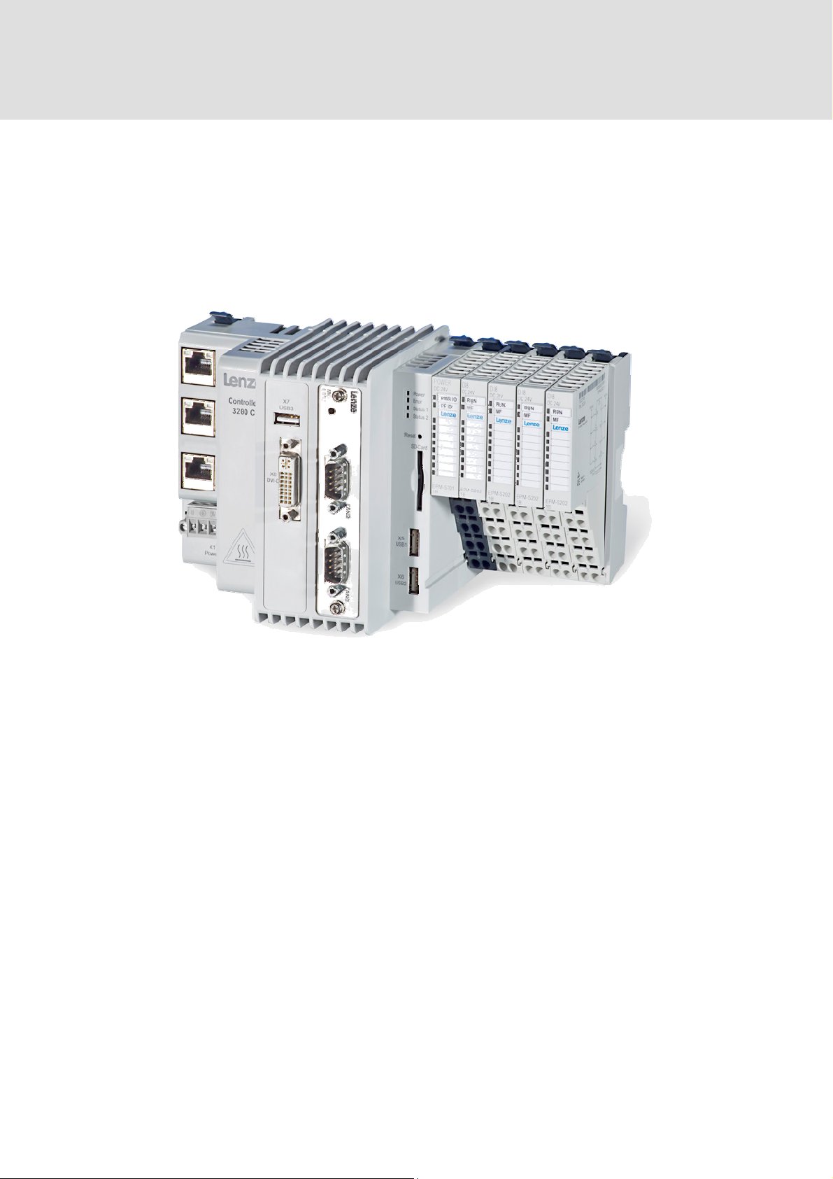
Industrial PC
L-force Controller 3241C - Backplane Bus
Programming Interface I/O-System 1000
Page 2

Page 3

Contents
Contents
1
Introduction ........................................................................................... 3
2 Architecture............................................................................................ 4
3 API functions ..........................................................................................5
3.1 Functio
3.2 Basic functio
3.2.1 Function: BpbOpen
3.2.2 Function: BpbClose
3.3 Diagno
3.3.1 Diagnostics functions
3.3.2 Service functions
3.3.3 Network management
3.4 Commu
3.4.1 SDO communication
3.4.2 SDO functions
3.4.3 SDO indexes
3.4.4 SDO block structure
3.4.5 Memory requirements fo
3.4.6 PDO communication.......................................................................................... 18
ns of the interface DLL.................................................................................. 5
stics, service functions and network management .................................... 7
nication....................................................................................................... 11
ns........................................................................................................... 6
...............................................................................................6
...............................................................................................6
...........................................................................................7
...................................................................................................9
...................................................................................... 10
.......................................................................................... 11
...................................................................................................... 12
......................................................................................................... 13
........................................................................................... 15
r SDO....................................................................... 17
3.4.7 PDO functions...................................................................................................... 19
3.4.8 Memory requirements fo
3.4.9 Example constellation
3.5 Status de
3.6 Error co
3.7 I/O mo
des ............................................................................................................... 23
dule types and their data width ................................................................. 26
scription of the backplane bus (state machine) .................................... 23
r process data....................................................... 20
....................................................................................... 20
4 Software ...............................................................................................28
4.1 Driver
4.2 Progra
4.3 Inclu
........................................................................................................................ 28
mming interface........................................................................................... 28
de and library files........................................................................................... 28
5 Definitions, acronyms, and abbreviations .........................................29
1
Page 4

Contents
2
Page 5
Introduction 1
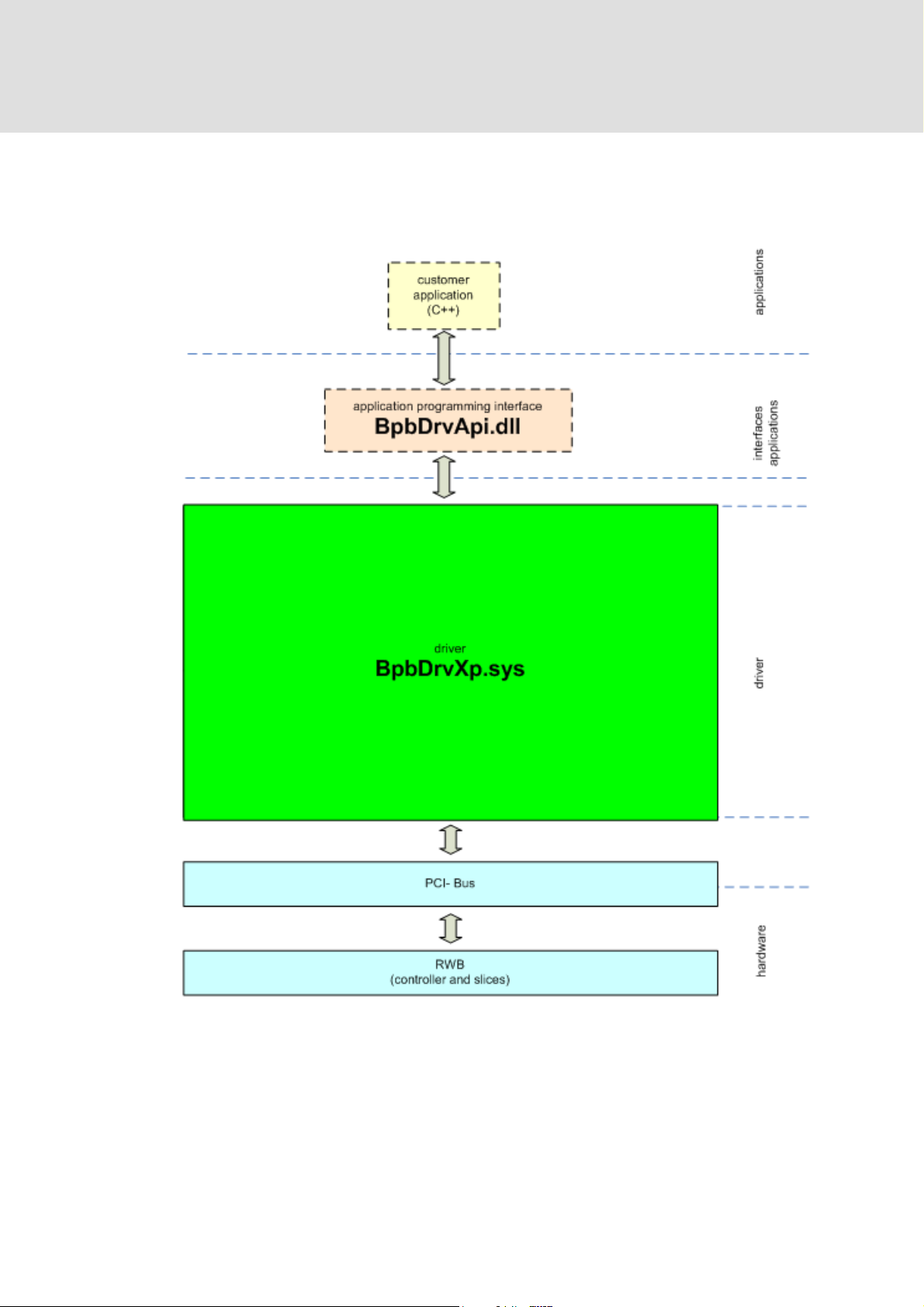
1 Introduction
This manual describes the programming interface for the on board I/O system 1000.
The L-force Controller 3241 and the I/O compound modules are connected via a
backplane bus. By means of an interface DLL (BpbDrvApi.dll), the connection of the
individual application to the backplane bus device driver (BpbDrvXp.sys) and the I/O
system is enabled.
Up to 64 I/O compound modules can be connected to the 3241 controller. Digital
input/output modules, analog modules, and counter modules are provided as I/O
compound modules. Further information can be found in the manual of the I/O
system 1000.
3
Page 6
2 Architecture
2 Architecture
In the following illustration the architecture of the backplane bus to the application is
shown in a detailed manner.
Abb. 1 Structure of the backplane bus driver
4
Page 7

API functions 3
3 API functions
The programming interface is based on the backplane bus device driver and provides
an interface for the transmission/reception of process data (PDOs) and configuration
data (SDOs).
By means of this interface, a cyclic thread is created, copying the process data from/to
the I/O modules. The grouping for the customer application interface is simplified, so
that there only is one group. During transmission this group contains all output data,
and during reception it contains all input data.
3.1 Functions of the interface DLL
The following functions
Function Description
BpbApiOpen
BpbApiClose
BpbApiGetVersion
BpbApiGetStates
BpbApiResetBpb
BpbApiGetError
BpbApiResetError
BpbApiReadSdo
BpbApiWriteSdo
BpbApiSetOperational
BpbApiReadPdo
BpbApiWritePdo
are provided:
Log on application on application interface
Log off application on application interface
Returns the version
Read out status of the backplane bus (BPB)
Carries out a reset on the BPB controller
Read last error message of the BPB
Resets the error memory in the BPB controller
Reading out the input buffer
Writing to the output buffer
Starts free-running BPB operation
Imports the process image
Writes the process image
In the following the functions listed above are specified.
5
Page 8

3 API functions
3.2 Basic functions
The basic functions serve to the connection establishment or connection termination:
3.2.1 Function: BpbOpen
Register to the hardware
identification. This handle must be transferred as the first parameter for all further
functions.
Parameters
[in] LPTSTR szAppName Name of the application to be registered
[out] PHANDLE hOpen Pointer to open context (handle) for identification
Return values
S_OK Successful
E_LOADED Incomplete (driver not loaded)
3.2.2 Function: BpbClose
Disconnection of the backplane bus
Parameter
[in] HANDLE hOpen Pointer to open context (handle) for identification
of the controller. The return value is a handle for
connection to the 3241 controller.
Return values
S_OK Successful
E_HANDLE Error during connection termination (handle is invalid)
6
Page 9

API functions 3
3.3 Diagnostics, service functions and network management
3.3.1 Diagnostics functions
The diagnos
tics function provide some return information on the version, available
errors, and states of the backplane buses.
BpbGetVersion function
The
BpbGetVersion function supplies the version of the backplane bus driver.
Parameter
[in] HANDLE hOpen Pointer to open context (handle) for identification
[out] PSTRING pszVersion Version of the backplane bus driver
Return values
S_OK Successful
E_HANDLE Incorrect (handle is invalid)
BpbGetError function
In the stat
us register an error status is signalised. It contains a byte error code. The
BpbGetError function reads out this error code from the status register of the
backplane bus.
Parameter
[in] HANDLE hOpen Pointer to open context (handle) for identification
[out] PUCHAR pbError Error code
Return values
S_OK Successful
E_HANDLE Incorrect (handle is invalid)
A description of the error code can be found in the chapter "Error code“.
7
Page 10

3 API functions
BpbGetStates function
Parameter
[in] HANDLE hOpen Pointer to open context (handle) for identification
[out] PBPBSTATES pBpbStates Pointer to the states structure
Return values
S_OK Successful
E_HANDLE Incorrect (handle is invalid)
The states are returned in the BpbStates structure. In the following the organisation
of this structure is shown.
BpbState structure
Structure of
UCHAR hRaw Raw value of the status information
Name
the status register:
hName Status information of the controller and the groups
Structure of the name
Structure of the name:
Bit 0 .. bit 1 Controller Status of the controller
Bit 2 .. bit 3 Group1 Status of group 1
Bit 4 .. bit 5 Group2 Status of group 2
Bit 6 .. bit 7 Group3 Status of group 3
The byte is divided according to the status byte of the 3241 controller status register
and the I/O modules configured.
Return values of the controller
1 BPB_ CONTROLLER_STATE_INIT
2 BPB_ CONTROLLER_STATE_PREOP
3 BPB_ CONTROLLER_STATE_OP
Return values of the group
0 BPB_GROUP_STATE_UNAVAILABLE
1 BPB_GROUP_STATE_INIT
2 BPB_GROUP_STATE_RUNNING
3 BPB_GROUP_STATE_ERROR
Please note: Under XP the grouping for the programming interface is simplified, so
that there only is one group. During transmission this group contains all output data,
and during reception it contains all input data.
8
Page 11

API functions 3
3.3.2 Service functions
The two functions BpbResetBpb and BpbResetError serve to carry out troubleshooting.
BpbResetBpb function
The service function BpbResetBpb car
ries out a reset of the backplane bus and restarts
the backplane bus controller.
Note:
After a reset, BpbSetOperational should be called to start cyclic communication.
Parameter
[in] HANDLE hOpen Pointer to open context (handle) for identification
Return values
S_OK Successful
E_HANDLE Incorrect (handle is invalid)
BpbResetError function
The service function BpbResetError d
eletes the fault memory in the status register.
Parameter
[in] HANDLE hOpen Pointer to open context (handle) for identification
Return values
S_OK Successful
E_HANDLE Incorrect (handle is invalid)
9
Page 12

3 API functions
3.3.3 Network management
By means of the BpbSetOperational network management function, the status of the
backplane bus can be changed over from Operational to PreOperational.
BpbSetOperational function
The
BpbSetOperational function implicitly executes the BpbReset function.
Parameter
[in] HANDLE hOpen Pointer to open context (handle) for identification
[in] ULONG ulCycleTime Cycle time for internal BPB cycle [μs]
[in] BOOLEAN bOperational Operational = TRUE or
Return values
S_OK Successful
E_HANDLE Incorrect (handle is invalid)
PreOperational = FALSE
10
Page 13

API functions 3
3.4 Communication
In this chapter the transmission/reception of process data (PDOs) and configuration
data (SDOs) is described.
3.4.1 SDO communication
Configuration data (SDOs)
During writi
ng the configuration data the SDOs are stored directly in an output buffer
of the driver. Access is basically initiated by the IPC. The BPB controller then responds
accordingly. If the SDOs can be written to the corresponding FIFO of the backplane
bus, they are transmitted. A definite job number is assigned to each SDO by the driver,
in order to be able to assign responses to the response FIFO and store them in the
corresponding input buffer of the application.
Output buffer
SDO +
Reception
Job number
FIFO
Transmission:
SDO
Application interface
Input buffer
Response +
Job number
Application
interface
Abb. 2 FIFOs, buffers, and job numbers
Response
FIFO
Reception:
Respond
11
Page 14

3 API functions
A configuration parameter of an I/O module is treated as an SDO in the IPC and is
transferred to the BPB controller via the FIFOs in the form of a structure, which
contains the data in a format suitable for DS 401. Access of the IPC to the BPB
controller is effected in 2 possible ways:
IPC BPB controller
Writing: Write request Status message
Reading: Read request Response
3.4.2 SDO functions
BpbReadSdo function
Parameter
[in] HANDLE hOpen Pointer to open context (handle) for identification
[out] PUCHAR pReadBuffer SDO memory area
[in] WORD usBufferSize Size of the memory area
[out] PWORD pusActualSdoSize Size of the memory area assigned
Return values
S_OK Successful
E_HANDLE Incorrect (handle is invalid)
E_MEMORY Incorrect (BPB message memory area overflown)
BpbWriteSdo function
Parameter
[in] HANDLE hOpen Pointer to open context (handle) for identification
[in] PUCHAR pWriteBuffer SDO memory area
[in] USHORT usBufferSize Size of the memory area
[in] USHORT usSdoCount Number of SDOs
[out] PUSHORT pusSdoWritten Number of SDOs written
Return values
S_OK Successful
E_HANDLE Incorrect (handle is invalid)
E_FIFO Incorrect (output buffer has overflown)
12
Page 15

API functions 3
3.4.3 SDO indexes
The following table provides a summary of possible telegrams:
Designation Index Subindex Description
DS301
Indexes 0-1FFF
Manufacturerspecific
DS401
Hardware/firmware
version
Software version 100A h
Module identification 1027 h
Module type
designation
See documentation for I/O system 1000
1009h
2028 h 1d – 40d Returns string[10] with the type
80d String[14] for config. file version of
the BPB controller
81d String[14] for ID of the BPB master
80d String[14] for version of Nios SW
(build#.major.minor.micro)
81d String[14] for the master version of
the BPB master
0d Number of disks
n Identification according to disk (1-
64)
designation of terminal n.
Module parameter
for….
13
Page 16

3 API functions
In the following the identification of the modules is described:
Module Value
DI_2X 0x001
DI_4X 0x003
DI_8X 0x005
DI_4X_3WIRE 0x006
DI_2X_NPN 0x002
DI_4X_NPN 0x004
DI_8X_NPN 0x007
DO_2X 0x101
DO_4X 0x104
DO_8X 0x106
DO_2X_2A 0x102
DO_2X_NPN 0x103
DO_4X_NPN 0x105
DO_8X_NPN 0x107
AI_2X_U 0x401
AI_4X_U 0x404
AI_2X_I 0x402
AI_4X_I 0x405
AO_2X_U 0x501
AO_4X_U 0x503
AO_2X_I 0x502
AO_4X_I 0x504
AI_2X_TC 0x403
AI_4X_R 0x406
CNT_1X_24V 0x991
CNT_1X_5V 0x992
CNT_2X_24V 0x993
CNT_2X_24VEC 0x994
SSI_1X 0x995
14
Page 17

API functions 3
3.4.4 SDO block structure
SDO memory area header 1. DWORD
Status register 2. DWORD
3. DWORD
SDOs
…
n. DWORD
BpbSdoBlockHeader
(binary data, according to SDO
package formats)
The structure of the SDO memory area results from the different SDO package
formats. The following package formats are defined there:
Write request (BpbSdoHeader, BpbWrite) status message (BpbSdoHeader)
Read request (BpbSdoHeader) response (BpbSdoHeader, BpbRead)
Each SDO (FIFO telegram) starts with a header, which is identical for the IPC and the
BPB controller:
Header
Structural element Type Bits Description FIFO
Index WORD 16-31 Index of the parameter
Subindex BYTE 8-15 Subindex of the parameter
Control BYTE 0-7 Bit 7 = 0 (read) / 1 (write)
1 DWORD
Bit 0-6 = job number
Via the index and subindex, the BPB controller basically decodes the action to be
executed and, if required, generates a suitable command for the BPB master, which
the backplane bus master in turn transmits to the I/O module/s. Since a telegram on
the BPB must only contain a maximum of 64 bytes of user data, a data volume greater
than that, if necessary, has to be fragmented into several individual telegrams by the
IPC. After processing, the BPB controller sends a status message on the response FIFO
to the IPC. The response contains the job number and one byte regarding the success
of the action.
15
Page 18

3 API functions
In the following the SDOs for writing/reading and the corresponding status
message/response are shown:
Write request
Structural element Type Bits Description FIFO
Header 1 DWORD
Value BYTE 24-31
Value BYTE 16-23
Number of values BYTE 8-15 Number of bytes (max. 64)
Reserved BYTE 0-7
Values WORD 2. WORD
WORD 1. WORD
WORD 4. WORD
WORD 3. WORD
WORD 6. WORD
WORD 5. WORD
0. WORD
1 DWORD
1 DWORD
1 DWORD
1 DWORD
For the sequence of the values, in the 2. and all following DWORD ascending byte
addresses are selected, respectively.
Status message (identical to the response to a read request)
Structural element Type Bits Description FIFO
Header 1 DWORD
Reserved BYTE 24-31
Reserved BYTE 16-23
Number of values BYTE 8-15 Number of bytes (max. 64)
Status BYTE 0-7 Status information (0 = OK)
1 DWORD
Read request
Structural element Type Bits Description FIFO
Header 1 DWORD
16
Page 19

API functions 3
Response
Structural element Type Bits Description FIFO
Header 1 DWORD
Value BYTE 24-31 2. value
Value BYTE 16-23 1. value
Number of values BYTE 8-15 Number of bytes
Status BYTE 0-7 Status information (0 = OK)
Values ARRAY Other values to be transmitted n DWORDs
Notes:
All SDOs are to be stored in a DWORD-aligned manner.
Job is completed automatically by the driver.
3.4.5 Memory requirements for SDO
For SDO ther
e are also two directions:
L-force Controller transmits control data/commands to the backplane bus
controller
Backplane bus controller transmits control data/status information to the
L-force Controller
1 DWORD
(max. 64)
For both directions FIFOs are used as mailbox. The size of the FIFOs is 128 bytes in
each case.
17
Page 20

3 API functions
I
3.4.6 PDO communication
Process data (PDO)
In order to r
ead process data from the backplane bus, the BpbReadPdo function is
used, reading the process input image. The process output image can be written to
the backplane bus by means of the BpbWritePdo function. The reading/writing of
PDOs is only possible in the Operational state.
Reading/writing the PDOs of a group is only transmitted from/to the BPB controller if
the group status is "RUNNING“. During the "INIT“ group status, the values are read as
0 (directly in the driver, not from the BPB controller).
By the BpdReadPdo and BpbWritePdo functions, a PDO block including a header
(contains the size of the PDOs and the status register) is provided or expected. In the
case of the writing access, the contents of the status register are ignored.
BPB driver
RWB_Read(...)
{
...
ReadDPRAM()
...
}
PC
DPRAM
Process input image
RWB_Write(...)
{
...
ReadDPRAM()
...
}
Process output image
Abb. 3 Reading/writing the process image
18
Page 21

API functions 3
3.4.7 PDO functions
BpbReadPdo function
Parameter
[in] HANDLE hOpen Pointer to open context (handle) for identification
[out] PUCHAR pReadBuffer PDO memory area
[in] WORD usBufferSize Size of the memory area
[out] PWORD pusActualPdoSize Size of the memory area assigned
Return values
S_OK Successful
E_HANDLE Incorrect (handle is invalid)
E_MEMORY Incorrect (BPB message memory area overflown)
BpbWritePDO function
Parameter
[in] HANDLE hOpen Pointer to open context (handle) for identification
[in] PUCHAR pWriteBuffer PDO memory area
[in] USHORT usBufferSize Size of the memory area
[out] PUSHORT pusSdoWritten Number of PDOs written
Return values
S_OK Successful
E_HANDLE Incorrect (handle is invalid)
PDO block structure
The structure of the process data results from the group configuration of the I/O
modules.
Size of the PDO memory area 1. DWORD
Status register 2. DWORD
3. DWORD
SDOs
…
n. DWORD
BpbPdoBlockHeader
(binary data, according to process
image)
After a read or write access the status register contains the current status of the BPB
and does not serve to change the status of the BPB.
19
Page 22

3 API functions
3.4.8 Memory requirements for process data
The memory requirements for process data can be calculated via the currently
available modules:
Terminal Process image Configurable Bytes @64 nodes
DI,DO 2x 2 bits
Always 1byte per terminal is
transmitted
DI,DO 4x 4 bits
(1byte)
DI,DO 8x 8 bits
(1byte)
AI,AO 2x12bits 4 bytes (2x16bits)
AI,AO 4x12bits 8 bytes (4x16bits)
Reading and writing are different with the regard to the maximum amount of data.
During reading, according to the table there is a maximum of 1280 bytes; during
writing a maximum of 512 bytes.
3.4.9 Example constellation
The example constellation of a randomly selected combination of I/O compound
modules is used as an illustration. After the address location has been c
following results:
64
64
64
256
512
arried out, the
Abb. 4 Example constellation
20
Page 23

API functions 3
In the next step, the BPB controller classifies the I/O compound modules determined
on the basis of their slice ID according to the categories "input“ or "output“.
Depending on the slice ID, the required number of bytes in the PI is determined on the
basis of a look-up table. (Inputs: blue, outputs: green)
Abb. 5 Dividing the disks into inputs and outputs
With the information determined, the memory mapping can be calculated. For the
case shown here the simplified assumption is that there only is 1 group for all inputs
and outputs in each case.
Abb. 6 Classification of the disks and calculation of the memory mapping
21
Page 24

3 API functions
INPUTS OUTPUT
Abb. 7 Memory image of inputs and outputs in the address area
22
Page 25

API functions 3
3.5 Status description of the backplane bus (state machine)
The switch-on procedure in the backplane bus is effected in several steps.
Status Transition Description
1. Init Initialisation of the peripherals, automatic transition to
the PreOperational state, and setting a status bit.
No PDO & SDO communication
2. PreOperational SDO communication possible
- Reception of configuration data for the individual
terminals
- Waiting for the "Start“ telegram, or repeated "Config“
L-force Controller -> BPB controller
- Transmission of the terminal data to the IPC
3. Operational
3.6 Error codes
The pro
gramming interface returns the following possible error codes. Errors are
returned as a bit mask, i.e. several error codes can be linked with each other in each
case.
Error list for the status register
(Error byte in the status register)
Error number Category Source Description
Dec Hex
0 0 - - No error; ok
11 B Warning BPB controller Synchronisation: DPRAM lock register
12 C Warning BPB controller Result FIFO full
31 1F Warning BPB driver Synchronisation: DPRAM lock register
32 20 Warning BPB driver Timeout: Reset
SDO & PDO communication possible
33 21 Warning BPB driver Timeout: ErrorReset
96 60 Error BPB controller Error during creation of group 1
97 61 Error BPB controller Error during creation of group 2
98 62 Error BPB controller Error during creation of group 3
99 63 Error BPB controller Groups ok, but cycle time not sufficient
100 64 Error BPB controller Error during processing the master queues
23
Page 26

3 API functions
Error number Category Source Description
Dec Hex
101 65 Error BPB controller Controller timeout during processing the master
102 66 Error BPB controller Error during the initialisation of the bus (error on
103 67 Error BPB controller Cycle time exceeded
104 68 Error BPB controller DPRAM semaphore timeout of group 1 (reading)
105 69 Error BPB controller DPRAM semaphore timeout of group 2 (reading)
106 6A Error BPB controller DPRAM semaphore timeout of group 3 (reading)
107 6B Error BPB controller DPRAM semaphore timeout of group 1 (writing)
108 6C Error BPB controller DPRAM semaphore timeout of group 2 (writing)
109 6D Error BPB controller DPRAM semaphore timeout of group 3 (writing)
116 74 Error BPB driver DPRAM semaphore timeout of group 1 (reading)
queues
one disk)
117 75 Error BPB driver DPRAM semaphore timeout of group 2 (reading)
118 76 Error BPB driver DPRAM semaphore timeout of group 3 (reading)
119 77 Error BPB driver DPRAM semaphore timeout of group 1 (writing)
120 78 Error BPB driver DPRAM semaphore timeout of group 2 (writing)
121 79 Error BPB driver DPRAM semaphore timeout of group 3 (writing)
181 B5 Fatal error BPB controller Synchronisation: DPRAM
182 B6 Fatal error BPB controller
200 C8 Fatal error BPB controller SDO timeout
201 C9 Fatal error BPB driver
220 DC Fatal error BPB driver SDO communication error (=> inhibit of SDO
communication)
A fatal error can only be eliminated by a reset of the BPB.
24
Page 27

API functions 3
The following SDO errors can occur:
Error list for the SDO status
(status byte in the second DWORD of the SDO response)
Error number Description
Dec Hex
0 0 No error; OK
8 8 Telegram timeout
40 28 Subindex out of range
63 3F Group number out of range
200 C8 SDO timeout FATAL Error
254 FE Subindex not supported
255 FF Index not supported
160 A0 Read Access on write-only parameter
161 A1 Write access on read-only parameter
170 AA Wrong lenght of data
25
Page 28

3 API functions
3.7 I/O module types and their data width
In this chapter a list of the available I/O modules is shown:
Disk Description Data width
Digital I/O
EPM−S200 2 digital inputs 2 bits
EPM−S201 4 digital inputs 4 bits
EPM−S202 8 digital inputs 8 bits
EPM−S203 4 digital inputs 3−wire 8 bits
EPM−S204 2 digital inputs NPN 2 bits
EPM−S205 4 digital inputs NPN 4 bits
EPM−S206 8 digital inputs NPN 8 bits
EPM−S300 2 digital outputs 0.5 A 2 bits
EPM−S301 4 digital outputs 0.5 A 4 bits
EPM−S302 8 digital outputs 0.5 A 8 bits
EPM−S303 2 digital outputs 0.5 A NPN 2 bits
EPM−S304 4 digital outputs 0.5 A NPN 4 bits
EPM−S305 8 digital outputs 0.5 A NPN 8 bits
EPM−S306 2 digital outputs 2 A 2 bits
EPM−S309 4 digital outputs 2 A 4 bits
EPM−S308 2 relay outputs
Analog I/O
EPM−S400 2 analog inputs 0 ... 10 V DC 2 x 16 bits
EPM−S401 4 analog inputs 0 ... 10 V DC 4 x 16 bits
EPM−S402 2 analog inputs 0/4 ... 20 mA 2 x 16 bits
EPM−S403 4 analog inputs 0/4 ... 20 mA 4 x 16 bits
EPM−S500 2 analog outputs 0 ... 10 V DC 2 x 16 bits
EPM−S501 4 analog outputs 0 ... 10 V DC 4 x 16 bits
EPM−S502 2 analog outputs 0/4 ... 20 mA 2 x 16 bits
EPM−S503 4 analog outputs 0/4 ... 20 mA 4 x 16 bits
Temperature measurement
EPM−S404 4(2) analog inputs resistor 4(2) x 16 bits
EPM−S405 2 analog inputs thermocouple 2 x 16 bits
26
Page 29

API functions 3
Disk Description Data width
Counter
EPM−S600 1 counter 32 bits, 24 V DC (reading,
setting, comparing)
EPM−S601 2 counters 32 bits, 24 V DC
(reading, setting)
EPM−S602 1 counter 32 bits, 5 V DC (reading,
setting)
EPM−S603 2 counters 32 bits, 24 V DC
(reading)
Encoder evaluation
EPM−S604 SSI 6 bytes input
12 bytes input/10 bytes output
12 bytes input/12 bytes output
8 bytes input/10 bytes output
12 bytes input/4 bytes output
27
Page 30

4 Software
4 Software
List of the software required for the individual application:
4.1 Driver
Name Description Directory
BpbDrvXp.sys Backplane bus driver for the
BpbDrvXp.inf Backplane bus driver
WdfCoInstaller01007.dll KDMF Framework ..\Windows\System32\
The driver is preinstalled in the WES2009 for the 3241 controller
4.2 Programming interface
Name Description Directory
BpbDrvApi.dll
Programming interface for access to
the backplane bus via the backplane
bus driver
The programming interface is preinstalled in the WES2009 for the 3241 controller.
4.3 Include and library files
The following include and library files are to be integrated in t
application:
..\Windows\System32\Drivers\
backplane bus
..\Windows\Inf\
installation routine
..\Windows\System32\
he individual C++
Include files
Name Description
BpbDrv.h Header file of the structures and definitions used
BpbDrvApi.h Header file of the macro definitions of the functions provided by the backplane bus
driver
BpbError.h Header file of the error definitions
Library files
Name Description
BpbDrvApi.lib Library of the programming interface for access to the backplane bus via the
backplane bus driver
Example application
Name Description
BpbApiSample C++ example application for connection to the I/O system 1000 using all functions
provided
28
Page 31

Definitions, acronyms, and abbreviations 5
5 Definitions, acronyms, and abbreviations
The following abbreviations are relevant for understanding this document :
IPC Industrial PC
RWB Backplane bus
SDO Service data object
PDO Process data object
DS401 CanOpen profile for “generic IO modules”
DPRAM Dual Ported RAM
DWORD 32-bit date
WORD 16-bit date
BYTE 8-bit date
PCI Peripheral Component Interconnection
DI Digital In
DO Digital Out
AI Analog In
AO Analog Out
API Application Programming Interface
DLL Dynamic Link Library
LIB Library
SYS System driver
BPB Backplane bus
29
Page 32

)
¬
|
Þ
© 11/2010
Lenze Automation GmbH
Hans-Lenze-Str. 1
D-31855 Aerzen
Germany
+49 (0)51 54 / 82-0
+49(0)5154/82-2800
Lenze@Lenze.de
www.Lenze.com
Service Lenze Service GmbH
Breslauer Straße 3
D-32699 Extertal
Germany
¬
|
00 80 00 / 24 4 68 77 (24 h helpline)
+49 (0)51 54 / 82-11 12
Service@Lenze.de
SHPIPCBPB.DvñEN1.0TD29
10987654321
 Loading...