

Page 1

3200 C E32GAC...
IPC 3241 C
Operating Instructions
EN
.Ok_
Ä.Ok_ä
Page 2

Please read these instructions before you start working!
Follow the enclosed safety instructions.
Tip!
Information and tools concerning the Lenze products can be found in the download area under
www.lenze.com
Page 3

Contents i
1 About this documentation 5. . . . . . . . . . . . . . . . . . . . . . . . . . . . . . . . . . . . . . . . . . . . . . . . . . . . . . .
1.1 Document history 5. . . . . . . . . . . . . . . . . . . . . . . . . . . . . . . . . . . . . . . . . . . . . . . . . . . . . .
1.2 Conventions used 6. . . . . . . . . . . . . . . . . . . . . . . . . . . . . . . . . . . . . . . . . . . . . . . . . . . . . .
1.3 Notes used 7. . . . . . . . . . . . . . . . . . . . . . . . . . . . . . . . . . . . . . . . . . . . . . . . . . . . . . . . . . . .
2 Safety instructions 8. . . . . . . . . . . . . . . . . . . . . . . . . . . . . . . . . . . . . . . . . . . . . . . . . . . . . . . . . . . . . .
2.1 General safety information 8. . . . . . . . . . . . . . . . . . . . . . . . . . . . . . . . . . . . . . . . . . . . . .
2.2 Product−specific safety instructions 11. . . . . . . . . . . . . . . . . . . . . . . . . . . . . . . . . . . . . . .
2.3 Safety instructions for the installation according to UL/CSA 12. . . . . . . . . . . . . . . . . . .
2.4 Residual hazards 14. . . . . . . . . . . . . . . . . . . . . . . . . . . . . . . . . . . . . . . . . . . . . . . . . . . . . . .
3 Product description 15. . . . . . . . . . . . . . . . . . . . . . . . . . . . . . . . . . . . . . . . . . . . . . . . . . . . . . . . . . . . .
3.1 Scope of supply 15. . . . . . . . . . . . . . . . . . . . . . . . . . . . . . . . . . . . . . . . . . . . . . . . . . . . . . . .
3.2 Application as directed 16. . . . . . . . . . . . . . . . . . . . . . . . . . . . . . . . . . . . . . . . . . . . . . . . .
3.3 Device features 17. . . . . . . . . . . . . . . . . . . . . . . . . . . . . . . . . . . . . . . . . . . . . . . . . . . . . . . .
3.4 Identification 18. . . . . . . . . . . . . . . . . . . . . . . . . . . . . . . . . . . . . . . . . . . . . . . . . . . . . . . . . .
3.5 Controls and displays 19. . . . . . . . . . . . . . . . . . . . . . . . . . . . . . . . . . . . . . . . . . . . . . . . . . .
3.6 UPS functionality 21. . . . . . . . . . . . . . . . . . . . . . . . . . . . . . . . . . . . . . . . . . . . . . . . . . . . . . .
3.7 "Real Time Clock" functionality 21. . . . . . . . . . . . . . . . . . . . . . . . . . . . . . . . . . . . . . . . . . .
3.8 Resetting the device (Reset) 21. . . . . . . . . . . . . . . . . . . . . . . . . . . . . . . . . . . . . . . . . . . . . .
4 Technical data 22. . . . . . . . . . . . . . . . . . . . . . . . . . . . . . . . . . . . . . . . . . . . . . . . . . . . . . . . . . . . . . . . . .
4.1 General data and operating conditions 22. . . . . . . . . . . . . . . . . . . . . . . . . . . . . . . . . . .
4.2 Mechanical data 23. . . . . . . . . . . . . . . . . . . . . . . . . . . . . . . . . . . . . . . . . . . . . . . . . . . . . .
4.3 Electrical data 23. . . . . . . . . . . . . . . . . . . . . . . . . . . . . . . . . . . . . . . . . . . . . . . . . . . . . . . . . .
5 Mechanical installation 24. . . . . . . . . . . . . . . . . . . . . . . . . . . . . . . . . . . . . . . . . . . . . . . . . . . . . . . . . .
5.1 Important notes 24. . . . . . . . . . . . . . . . . . . . . . . . . . . . . . . . . . . . . . . . . . . . . . . . . . . . . . . .
5.2 Dimensions 25. . . . . . . . . . . . . . . . . . . . . . . . . . . . . . . . . . . . . . . . . . . . . . . . . . . . . . . . . . . .
5.3 Mounting 26. . . . . . . . . . . . . . . . . . . . . . . . . . . . . . . . . . . . . . . . . . . . . . . . . . . . . . . . . . . . .
5.4 Dismounting 27. . . . . . . . . . . . . . . . . . . . . . . . . . . . . . . . . . . . . . . . . . . . . . . . . . . . . . . . . .
Lenze ¯ BA_3241C ¯ 4.0
3
Page 4

Contentsi
6 Electrical installation 28. . . . . . . . . . . . . . . . . . . . . . . . . . . . . . . . . . . . . . . . . . . . . . . . . . . . . . . . . . . .
6.1 Important notes 28. . . . . . . . . . . . . . . . . . . . . . . . . . . . . . . . . . . . . . . . . . . . . . . . . . . . . . . .
6.2 EMC−compliant wiring 29. . . . . . . . . . . . . . . . . . . . . . . . . . . . . . . . . . . . . . . . . . . . . . . . . .
6.3 Connecting voltage supply (24 V) 30. . . . . . . . . . . . . . . . . . . . . . . . . . . . . . . . . . . . . . . . .
6.3.1 Connection plan 30. . . . . . . . . . . . . . . . . . . . . . . . . . . . . . . . . . . . . . . . . . . . . . .
6.3.2 Mains connection (24 V) 30. . . . . . . . . . . . . . . . . . . . . . . . . . . . . . . . . . . . . . . .
6.4 Interfaces for peripheral devices 31. . . . . . . . . . . . . . . . . . . . . . . . . . . . . . . . . . . . . . . . . .
6.4.1 UPS connection 31. . . . . . . . . . . . . . . . . . . . . . . . . . . . . . . . . . . . . . . . . . . . . . . .
6.4.2 DVI interface 31. . . . . . . . . . . . . . . . . . . . . . . . . . . . . . . . . . . . . . . . . . . . . . . . . .
6.4.3 Ethernet interface 32. . . . . . . . . . . . . . . . . . . . . . . . . . . . . . . . . . . . . . . . . . . . . .
6.4.4 USB interface 33. . . . . . . . . . . . . . . . . . . . . . . . . . . . . . . . . . . . . . . . . . . . . . . . . .
6.4.5 Communication interface (MC card) 33. . . . . . . . . . . . . . . . . . . . . . . . . . . . . .
6.4.6 SD card interface 33. . . . . . . . . . . . . . . . . . . . . . . . . . . . . . . . . . . . . . . . . . . . . . .
7 Maintenance 34. . . . . . . . . . . . . . . . . . . . . . . . . . . . . . . . . . . . . . . . . . . . . . . . . . . . . . . . . . . . . . . . . . .
7.1 Regular checks 34. . . . . . . . . . . . . . . . . . . . . . . . . . . . . . . . . . . . . . . . . . . . . . . . . . . . . . . . .
7.2 Cleaning 34. . . . . . . . . . . . . . . . . . . . . . . . . . . . . . . . . . . . . . . . . . . . . . . . . . . . . . . . . . . . . .
7.3 Exchanging GapPad strips 35. . . . . . . . . . . . . . . . . . . . . . . . . . . . . . . . . . . . . . . . . . . . . . .
8 Index 36. . . . . . . . . . . . . . . . . . . . . . . . . . . . . . . . . . . . . . . . . . . . . . . . . . . . . . . . . . . . . . . . . . . . . . . . .
4
Lenze ¯ BA_3241C ¯ 4.0
Page 5

About this documentation
0Fig. 0Tab. 0
1 About this documentation
Contents
This documentation provides information on the application as directed of the
IPC 3241 C in the Lenze "PC−based Automation" control system.
Software manual "Industrial PC"
Here you can find detailed information on the parameter setting and
configuration of the Lenze IPCs.
Target group
This documentation is directed at qualified skilled personnel according to IEC 60364.
Qualified skilled personnel are persons who have the required qualifications to carry out
all activities involved in installing, mounting, commissioning, and operating the
product.
1
Document history
1.1 Document history
Version Description
4.0 07/2014 TD17 ¯ Amended by EAC conformity
¯ General updates
¯ New layout
3.0 12/2013 TD29 New designation and general revision
2.0 11/2011 TD29 General revision and UL approval
1.0 09/2010 TD29 First edition
Lenze ¯ BA_3241C ¯ 4.0
5
Page 6

1
About this documentation
Conventions used
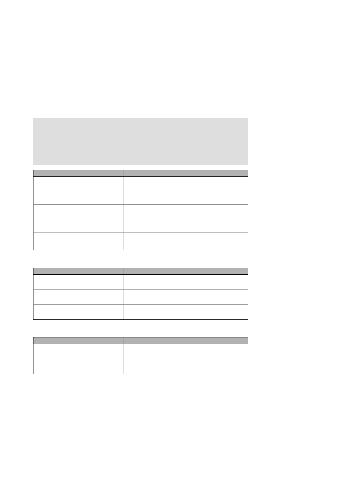
1.2 Conventions used
This documentation uses the following conventions to distinguish between different
types of information:
Type of information Writing Example/notes
Spelling of numbers
Decimal Normal spelling Example: 1234
Decimal separator Point The decimal point is always used.
Warnings
UL warnings
UR warnings
Text
Program name » « PC software
Icons
Page reference
Documentation reference
For example: 1234.56
Given in English and French
For example: Lenze »Engineer«
Reference to another page with additional
information
For instance:
Reference to another documentation with
additional information
Example:
16 = see page 16
EDKxxx = see documentation EDKxxx
6
Lenze ¯ BA_3241C ¯ 4.0
Page 7
About this documentation
1.3 Notes used
The following pictographs and signal words are used in this documentation to indicate
dangers and important information:
Safety instructions
Layout of the safety instructions:
Danger!
(characterises the type and severity of danger)
Note
(describes the danger and gives information about how to prevent
dangerous situations)
Pictograph and signal word Meaning
Danger of personal injury through dangerous electrical
voltage
Danger!
Danger!
Stop!
Reference to an imminent danger that may result in death
or serious personal injury if the corresponding measures are
not taken.
Danger of personal injury through a general source of
danger
Reference to an imminent danger that may result in death
or serious personal injury if the corresponding measures are
not taken.
Danger of property damage
Reference to a possible danger that may result in property
damage if the corresponding measures are not taken.
1
Notes used
Application notes
Pictograph and signal word Meaning
Note!
Tip!
Special safety instructions and application notes
Pictograph and signal word Meaning
Warnings!
Warnings!
Important note to ensure trouble−free operation
Useful tip for easy handling
Reference to another document
Safety note or application note for the operation according
to UL or CSA requirements.
The measures are required to meet the requirements
according to UL or CSA.
Lenze ¯ BA_3241C ¯ 4.0
7
Page 8

2
2 Safety instructions
2.1 General safety information
Scope
The following general safety instructions apply to all Lenze drive and automation
components.
The product−specific safety and application notes given in this documentation must be
observed!
For your own safety
Safety instructions
General safety information
Danger!
Disregarding the following basic safety measures may lead to severe
personal injury and damage to material assets!
¯ Lenze drive and automation components ...
... must only be used for the intended purpose.
... must never be operated if damaged.
... must never be subjected to technical modifications.
... must never be operated unless completely assembled.
... must never be operated without the covers/guards.
... can − depending on their degree of protection − have live, movable or rotating parts
during or after operation. Surfaces can be hot.
¯ For Lenze drive and automation components ...
... only use approved accessories.
... only use original manufacturer spare parts.
¯ All specifications of the corresponding enclosed documentation must be
observed.
This is vital for a safe and trouble−free operation and for achieving the specified
product features.
The procedural notes and circuit details provided in this document are proposals
which the user must check for suitability for his application. The manufacturer does
not accept any liability for the suitability of the specified procedures and circuit
proposals.
¯ Only qualified skilled personnel are permitted to work with or on Lenze drive and
automation components.
According to IEC 60364 or CENELEC HD 384, these are persons ...
... who are familiar with the installation, assembly, commissioning and operation of
the product,
... possess the appropriate qualifications for their work,
... and are acquainted with and can apply all the accident prevent regulations,
directives and laws applicable at the place of use.
Transport, storage
¯ Transport and storage in a dry, low−vibration environment without aggressive
atmosphere; preferably in the packaging provided by the manufacturer.
– Protect against dust and impacts.
– Observe climatic conditions according to the technical data.
8
Lenze ¯ BA_3241C ¯ 4.0
Page 9

Safety instructions
General safety information
Mechanical installation
¯ Install the product according to the regulations of the corresponding
documentation. In particular observe the section "Operating conditions" in the
chapter "Technical data".
¯ Provide for a careful handling and avoid mechanical overload. During handling
neither bend components, nor change the insulation distances.
¯ The product contains electrostatic sensitive devices which can easily be damaged
by short circuit or static discharge (ESD). Thus, electronic components and
contacts must not be touched unless ESD measures are taken beforehand.
Electrical installation
¯ Carry out the electrical installation according to the relevant regulations (e. g.
cable cross−sections, fusing, connection to the PE conductor). Additional notes are
included in the documentation.
¯ When working on live products, observe the applicable national regulations for
the prevention of accidents (e.g. BGV 3).
2
¯ The Instructions contain notes concerning wiring according to EMC regulations
(shielding, earthing, filters and cable routing). The compliance with limit values
required by the EMC legislation is the responsibility of the manufacturer of the
machine or system.
Warning: The inverters are automation components which can be used in industrial
environment according to EN 61000−6−4. These products may cause radio
interference in residential areas. If this happens, the operator may need to take
appropriate action.
¯ For compliance with the limit values for radio interference emission at the site of
installation, the components − if specified in the technical data − have to be
mounted in housings (e. g. control cabinets). The housings have to enable an
EMC−compliant installation. In particular observe that for example control cabinet
doors preferably have a circumferential metallic connection to the housing.
Reduce openings or cutouts through the housing to a minimum.
¯ Only plug in or remove pluggable terminals in the deenergised state!
Commissioning
¯ If required, you have to equip the system with additional monitoring and
protective devices in accordance with the respective valid safety regulations (e. g.
law on technical equipment, regulations for the prevention of accidents).
Lenze ¯ BA_3241C ¯ 4.0
9
Page 10

2
Maintenance and servicing
¯ The components are maintenance−free if the required operating conditions are
¯ If the cooling air is polluted, the cooling surfaces may be contaminated or the air
¯ After the system has been disconnected from the supply voltage, live components
Disposal
¯ Recycle or dispose of the product according to the applicable regulations.
Safety instructions
General safety information
observed.
vents may be blocked. Under these operating conditions, the cooling surfaces and
air vents must be cleaned at regular intervals. Never use sharp objects for this
purpose!
and power connections must not be touched immediately because capacitors may
be charged. Please observe the corresponding notes on the device.
10
Lenze ¯ BA_3241C ¯ 4.0
Page 11

Safety instructions
Product−specific safety instructions
2.2 Product−specific safety instructions
¯ The device is classified as a class A device and can cause radio interference in
residential areas. In this case, the operator may have to take special measures.
Any costs arising from these measures have to be paid by the operator.
¯ In case of error the device has to be switched to a deenergised state immediately.
For this, disconnect the supply connector and a possibly available UPS pack.
Afterwards the device is to be sent to the manufacturer. The address can be found
on the back of this documentation. For return, please use the original packaging!
¯ Printed circuit boards which might be damaged by short circuit or electrostatic
discharge (ESD) must be handled appropriately.
¯ If an optional battery pack (ACCU−PACK) is used:
– Connect the battery pack before switching on the standard device.
– The standard device is only deenergised if the supply cable and the battery pack
connecting cable have been disconnected.
– If the standard device is disconnected from the mains for a longer time, the
supply cable of the battery pack must be disconnected, so that the rechargeable
batteries are not damaged by a possible exhaustive discharge.
– When being stored, the batteries are losing energy over time. Hence, the
batteries must be fully charged by means of the standard device after a storage
period of six months at the latest.
– The batteries of the battery pack must not be charged by means of external
battery chargers. Use the ACU−UPS power supply unit of the standard device for
this purpose.
2
¯ If an optional capacitor pack (CAPS−PACK) is used:
– Connect the capacitor pack before switching on the standard device.
– The standard device is only deenergised if the supply cable and the capacitor
pack connecting cable have been disconnected.
– The capacitor pack is only deenergised if its capacitors are discharged.
– The capacitor pack must not be charged by means of external battery chargers.
Lenze ¯ BA_3241C ¯ 4.0
11
Page 12

2
2.3 Safety instructions for the installation according to UL/CSA
Safety instructions
Safety instructions for the installation according to UL/CSA
Approval
Underwriter Laboratories (UL), UL508 and CSA C22.2 No. 142−M1987, (UL File Number
E236341)
Ratings
¯ Input 24 V DC, max. 1.7 A
¯ Max. Surrounding temperature:
– 45 °C, vertical (upright) mounting
– 50 °C, horizontal mounting
Warnings!
Field Wiring Markings
Wiring Terminal MSTB 2.5/3−STF−5.08:
¯ Use Copper Wire only.
2
)
¯ AWG 18 ... 12 (0.82 ... 3.3 mm
¯ Torque 5 ... 7 lb−in (0.5 ... 0.6 Nm)
Device
¯ These devices are open type programmable controllers, provided with
housing for use in pollution degree 2 and controlled environment only.
¯ For use in max. surrounding temperature:
– 45 °C, vertical (upright) mounting
– 50 °C, horizontal mounting
Optional filed bus module
¯ Use only together with appropriate cable connectors, provided with
screws for securement and secure connector to avoid loosening.
12
Lenze ¯ BA_3241C ¯ 4.0
Page 13

Safety instructions
Safety instructions for the installation according to UL/CSA
Homologation
Underwriter Laboratories (UL), UL508 et CSA C22.2 n° 142−M1987, (n° de dossier UL
E236341)
Caractéristiques assignées
¯ Entrée 24 V CC, maximum 1.7 A
¯ Température ambiante maximale :
– 45 °C, montage vertical
– 50 °C, montage horizontal
Warnings!
Marquage du câblage à pied d’oeuvre
Bornier de câblage MSTB 2.5/3−STF−5.08 :
¯ Utiliser exclusivement des conducteurs en cuivre.
2
¯ AWG 18 ... 12 (0.82 ... 3.3 mm
¯ Couple de 5 ... 7 lb−in (0.5 ... 0.6 Nm)
Appareil
¯ Ces appareils sont des contrôleurs programmables à circuit ouvert avec
un coffret de protection destinés uniquement à un environnement
contrôlé caractérisé par le degré de pollution 2.
¯ Températures ambiantes maximales admissibles :
– 45 °C, montage vertical
– 50 °C, montage horizontal
Module bus en option
¯ A utiliser exclusivement avec des connecteurs de câble à vis adaptés.
Fixer les connecteurs pour éviter toute déconnexion.
)
2
Lenze ¯ BA_3241C ¯ 4.0
13
Page 14

2
2.4 Residual hazards
Safety instructions
Residual hazards
Danger!
Hot surface during operation
The heatsink at the back of the device gets very hot during operation.
Possible consequences:
¯ Burns when touching the heatsink.
¯ Fire or smouldering fire if flammable material is placed near the
heatsink or may get to it.
Protective measures:
¯ Before working on the device, check its heatsink temperature.
¯ Select the mounting location so that the operating conditions
mentioned in the technical data are permanently guaranteed.
14
Lenze ¯ BA_3241C ¯ 4.0
Page 15

3 Product description
EPM-S701
Product description
Scope of supply
3
IPC 3241 C
Fig. 3−1 IPC 3241 C with connected I/O system 1000 (grey)
I/O System 1000
System manual "I/O system 1000"
Here you can find detailed information on the I/O system 1000.
3.1 Scope of supply
Number Name
1 IPC 3241 C
1 Connection plug for voltage supply
1 SD card (inserted)
1 Contact cover
1 Mounting instructions
Note!
After receipt of the delivery, check immediately whether the items match
the accompanying papers. We do not accept any liability for deficiencies
claimed subsequently.
Claim
¯ visible transport damage immediately to the forwarder
¯ visible deficiencies/incompleteness immediately to your Lenze
representative.
32xxC_005
Lenze ¯ BA_3241C ¯ 4.0
15
Page 16

3
3.2 Application as directed
The IPC is used as directed if it is solely used for implementing control and operating
concepts or for presenting information in usual industrial and commercial fields. A
different use, or one beyond these purposes, is not permissible.
A use that is not intended also includes a use harbouring fatal risks or dangers which,
without the provision of exceptionally high safety measures, may result in death, injury
or damage to material assets.
The IPC in particular must not be used ...
¯ in private areas
¯ in potentially explosive atmospheres
¯ in areas with harmful gases, oils, acids, radiation, etc.
¯ in applications where vibration and impact loads occur which exceed the
¯ to execute safety functions, as for example
Product description
Application as directed
requirements of EN 61131−2.
– in the air−traffic control / in flight control systems
– for monitoring/controlling nuclear reactions
– for monitoring/controlling mass transportation
– for monitoring/controlling medical systems
– for monitoring/controlling weapons systems
In order to ensure the protection of persons and material assets, higher−level safety
systems must be used!
16
Lenze ¯ BA_3241C ¯ 4.0
Page 17

3.3 Device features
Range IPC 3241 C
Design ¯ Mounting on standard DIN rail (35 mm)
Equipment
Processor type
Fanless
Memory
RAM 1 GB
ROM (Flash) 4 GB
SD/SDHC card 128 MB
Retain memory 1024 kB
Interfaces
SD/SDHC card 1
Ethernet 3
USB 2.0 3
DVI−D 1
ACU
(UPS function)
Communication
(MC card)
Control/display elements
Reset button ü
Diagnostic LEDs 4
Operating system
Runtime software
Logic ü
Motion ü
3)
Visu
1) 2 x LAN (with integrated switch, 10 or 100 Mbps)
2) For external battery pack (ACCU−PACK) or capacitor pack (CAPS−PACK)
3) Visualisation for using an external Monitor Panel with DVI/USB Extender (accessories)
¯ I/O system 1000 can be connected via internal backplane bus
¯ Intelâ chip set US15W
¯ Intelâ GMA 500 graphics, direct X 9.0E, open GL 2.0
¯ AMIBIOS8â (password protection)
¯ ACPI 3.0 compliant power management
Atomä
1.6 GHz
512 kB L2 cache
DDR2−RAM
1)
2)
1
1
Windowsâ Embedded Standard 2009
VisiWinNET
â
Compact CE, 500 Power Tags
1 x LAN (10, 100 or 1000 Mbps)
Product description
Device features
3
Lenze ¯ BA_3241C ¯ 4.0
17
Page 18

3
Product description
Identification
3.4 Identification
Type:
Fig. 3−2 Typenschild
Pos. Description
1 Manufacturer
2 Certification
3 Type designation
4 Technical data
5 Serial number as bar code and numerically
6 Material number (customer−specific)
7 Type code/order number
Type code
IPC 3241 C
MC card
0 = without
1 = MC−ETH
3 = MC−ETC
5 = MC−PBM
6 = MC−PBS
7 = MC−PNC
8 = MC−PND
9 = MC−CAN2 with PCAN Light licence
D = MC−ISI
Input:
HW: SW:
32xxC_002
E32GAC10000C4H x XXX−01005000000
18
Lenze ¯ BA_3241C ¯ 4.0
Page 19

3.5 Controls and displays
1
0
1
2
Product description
Controls and displays
3
4
5
6
Fig. 3−3 Control and display elements
Pos. Description
A IPC 3241 C
B Locking lever (DIN rail)
C Backplane bus contacts
D Guide for DIN rail with thermal connection via GapPad strips
E Status LEDs ( 20)
F Reset button
G Contact cover
3
32xxC−001
Lenze ¯ BA_3241C ¯ 4.0
19
Page 20

3
Product description
Controls and displays
LED status displays
LED
Color 1 / Color 2
Power
Green Is ON
Yellow
Green Yellow Blinking
Green Blinking
Green Yellow Blinking
Error
Red Blinking
Green Red Blinking
Status 1 ("busy")
Green
Green Yellow Blinking
Status 2
− − No response
Interval Meaning
constantly
Is ON
constantly
Blinking
(2.0 Hz)
(0.5 Hz)
(5.0 Hz)
(5.0 Hz)
(5.0 Hz)
(5.0 Hz)
Is ON
constantly
Blinking
(0.5 Hz)
(0.5 Hz)
Starting sequence properly completed.
¯ No pending error
¯ IPC switched on
¯ Supply voltage OK
The supply voltage has fallen below the minimum value.
Status after switch−on/restart
System clock is not synchronised (missing time
information).
Note:
If the IPC is switched off for longer than two weeks, the set
time information is lost.
¯ The next starting sequence generates a logbook entry
(power LED is blinking green).
¯ Set the current time manually via the »WebConfig«
(parameter 91).
Battery pack (ACCU−PACK) or capacitor pack (CAPS−PACK) is
not fully charged.
The length of the dark bar shows the state of charge:
¯ ACCU/CAPS−PACK almost dead: long dark bar
¯ ACCU/CAPS−PACK almost fully charged: short dark bar
Error status of the battery pack (ACCU−PACK) or capacitor
pack (CAPS−PACK)
UPS function not available, possible cause:
¯ Connection to ACCU/CAPS−PACK interrupted
¯ ACCU/CAPS−PACK not connected, cable break/short
circuit
Error:
¯ Fatal error (abort)
¯ SD card not available/not inserted correctly
¯ No operating system licence available
Mains switching required
Operating status:
¯ IPC running
¯ PLC project running
Starting sequence of the IPC is active
User action required:
¯ Load PLC project (PLC was started, project is not running)
¯ Remove USB stick
20
Lenze ¯ BA_3241C ¯ 4.0
Page 21

Product description
3.6 UPS functionality
In case of supply voltage failure, the UPS functionality (uninterrupted current supply) of
the device provides a backup function for saving the user data (retain variables, logbook
data) before the device will be switched off.
In order to minimise the power consumption and increase the safety during the buffer
times, circuitry parts that are not required can optionally be switched off during a supply
voltage failure (e.g. supply of the backplane bus, supply of the devices connected to the
USB ports).
IPC 3241 C
UPS functionality via ... ¯ External battery pack (ACCU−PACK)
¯ External capacitor pack (CAPS−PACK)
Storage medium for backup data SD/SDHC card
Buffer time sufficient for ... 1 MB of retain and logbook data
Documentation for "ACCU−PACK"/"CAPS−PACK"
Here you can find detailed information on ...
¯ Battery pack (ACCU PACK);
¯ Capacitor pack (CAPS−PACK).
3
UPS functionality
3.7 "Real Time Clock" functionality
The operating system contains the CMOS−RTC time via a maintenance−free chip.
The CMOS−RTC time is internally saved for a minimum period of 14 days. Then the time
must be set again manually via the »WebConfig« (parameter 91).
required.
3.8 Resetting the device (Reset)
To reset the device, press the reset button ( 19).
A battery is not
Lenze ¯ BA_3241C ¯ 4.0
21
Page 22

4
Technical data
General data and operating conditions
4 Technical data
4.1 General data and operating conditions
General data
Conformity and approval
Conformity
CE 2004/108/EC EMC Directive
EAC TP TC 020/2011
(TR CU 020/2011)
Approval
UL UL 508
CSA C22.2
Other
RoHS 2011/65/EU Products are lead−free acc. to directive.
Protection of persons and device protection
Enclosure IP20
Electrical isolation
To the fieldbus Depending on the used MC card
To the process level None
Insulation resistance IEC 61131−2
Protective measures Against short circuit
Electromagnetic
compatibility of technical
means
Process Control Equipment (File−No. E236341)
Eurasian Conformity
TR CU: Technical Regulation of
Customs Union
EMC
Interference emission EN 61000−6−4 Class A (industrial premises)
Noise immunity EN 61000−6−2
Industrial premises
EN 61000−4−2 ESD; severity 3, i.e.
EN 61000−4−3 RF interference (housing)
EN 61000−4−4 Burst, severity level 3
EN 61000−4−5 Surge, severity 1
EN 61000−4−6 RF cable−guided
Air discharge: 8 kV,
4 kV with contact discharge
80 MHz 1000 MHz, 10 V/m 80 % AM
(1 kHz)
150 kHz 80 MHz, 10 V/m 80 % AM
(1 kHz)
22
Lenze ¯ BA_3241C ¯ 4.0
Page 23

Technical data
Operating conditions
Ambient conditions
Climatic
Storage/transport EN 60721−3−2 2K3: −25 ... +70 °C
Operation EN 60721−3−2 3K3:
Horizontal mounting: 0 ... +50 °C
Vertical mounting: 0 ... +45 °C
Air humidity EN 60721−3−3 3K3 (without condensation, relative humidity 10 ... 95 %)
Pollution EN 61131−2 Pollution degree 2
Mechanical
Vibration EN 61131−2 1 g
Shock EN 61131−2 15 g
Site altitude
Storage/transport < 12000 m amsl
Operation < 3000 m amsl
Mounting conditions
Mounting place In the control cabinet
Mounting position ¯ Horizontal
¯ Vertical
– LAN connections point downwards ( 26)
– With reduced ambient temperature range
Mounting type Clip mounting on DIN rail according to DIN EN 60715 (TH
35 x 7.5 or TH 35 x 15); maximum of 20 plug cycles, then
GapPad strips must be exchanged ( 35)
4
Mechanical data
4.2 Mechanical data
Type
3241 C
Dimensions without MC−Card
Dimensions Mass
B x H x T [mm] [kg]
136 x 105 x 112 0.6
4.3 Electrical data
Type
Voltage Current Power
[V DC] [A] [W] [A] [W] [A]
3241 C
24
(+18 ... +30,
1) Power without MC card and without USB consumer
2) With battery pack (ACCU−PACK) / capacitor pack (CAPS−PACK): +20 ... +30 V DC
+/−0 %)
2)
Supply
Stand−alone With maximum
1.3 31.2 1.8 41.0 Max. 0.6
configuration of I/O system
1)
1000 (5 V/1.7 A)
Current Power Charging
ACCU−PACK
CAPS−PACK
current
Lenze ¯ BA_3241C ¯ 4.0
23
Page 24

5
5 Mechanical installation
5.1 Important notes
Mechanical installation
Important notes
Danger!
Hot surface during operation
The heatsink at the back of the device gets very hot during operation.
Possible consequences:
¯ Burns when touching the heatsink.
¯ Fire or smouldering fire if flammable material is placed near the
heatsink or may get to it.
Protective measures:
¯ Before working on the device, check its heatsink temperature.
¯ Select the mounting location so that the operating conditions
mentioned in the technical data are permanently guaranteed.
Note!
On the rear of the device, there are two GapPad strips. These strips serve
to thermally connect the device to the DIN rail. If the strips are defective,
they must be replaced ( 35).
Mounting of the device on the DIN rail is limited to 20 plug cycles. Then
the GapPad strips must be exchanged.
New GapPad strips are available from Lenze (order number EPCZMEG).
¯ The mounting site must always comply with the operating conditions stated in
the technical data. Take additional measures if necessary.
¯ The mechanical connections must always be ensured.
¯ The mounting rail and the mounting plate in the control cabinet must be
electrically conductive and free of lacquer.
¯ Attach and detach IPC and modules of the I/O system 1000 only when the supply
voltage is switched off. Otherwise, they could be damaged by short circuits.
¯ Always arrange the modules from left to right starting with the IPC directly
followed by a power supply module EMP−S701 on the right side.
¯ The module must always be installed directly next to each other. Free slots
between the modules are not permissible because otherwise the backplane bus
would be interrupted.
¯ The side contacts of the last module always must be covered with the supplied
contact cover. Otherwise, the modules may be damaged by short circuit or static
discharge.
24
Lenze ¯ BA_3241C ¯ 4.0
Page 25

5.2 Dimensions
136 mm
112 mm
Mechanical installation
Dimensions
150 mm
35 mm
5
105 mm
Fig. 5−1 Dimensions and mounting clearances
100 mm
32xxC_001 32xxC_003
Lenze ¯ BA_3241C ¯ 4.0
25
Page 26

5
5.3 Mounting
Mechanical installation
Mounting
Stop!
Short circuit on the backplane bus contact
The backplane bus signals are forwarded to the adjacent module of the
I/O system 1000 via a contact strip. If electrically conductive material
contacts this contact strip, a short circuit can be caused. Moreover,
touching the contact strip can cause a static discharge.
Possible consequences:
¯ Destruction of the device and/or the modules.
Protective measures:
Plug on the contact cover provided in the scope of supply, ...
¯ on to the side contacts of the last I/O module or
¯ if no module of the I/O system 1000 is added.
1
Fig. 5−2 Mounting
Pos. Description
A Contact cover
How to mount the Controller:
1
2
0
32xxC_004
1. Loosen the locking lever for the DIN rail.
2. Put the Controller on the DIN rail.
3. Shut the locking lever.
26
Lenze ¯ BA_3241C ¯ 4.0
Page 27

5.4 Dismounting
Danger!
Hot surface during operation
The heatsink at the back of the device gets very hot during operation.
Possible consequences:
¯ Burns when touching the heatsink.
¯ Fire or smouldering fire if flammable material is placed near the
heatsink or may get to it.
Protective measures:
¯ Before working on the device, check its heatsink temperature.
¯ Select the mounting location so that the operating conditions
mentioned in the technical data are permanently guaranteed.
Mechanical installation
Dismounting
5
2
1
OFF
3
Fig. 5−3 Disassembly
How to remove the Controller:
1. Switch off the supply voltage.
2. Loosen the locking lever for the DIN rail.
2
32xxC_007
3. Remove the Controller from the DIN rail.
Lenze ¯ BA_3241C ¯ 4.0
27
Page 28

6
6 Electrical installation
6.1 Important notes
The installation must be carried out by qualified, skilled personnel familiar with the
applicable national standards.
Electrical installation
Important notes
Stop!
Short circuit and static discharge
The device contains components which are endangered in the case of
short circuit or static discharge.
Possible consequences:
¯ The device or parts of it will be destroyed.
Protective measures:
¯ Always switch off the voltage supply when working on the device. This
particularly applies:
– Before connecting / disconnecting connectors.
– Before plugging in / plugging out modules.
¯ All persons handling printed circuit boards have to take account of ESD
measures.
¯ Contacts of plug connectors must not be touched.
¯ Printed circuit boards may be touched only at places free from
electrical contacts and may be placed only on appropriate materials
(e.g. on ESD packaging or conductive foam material).
¯ Printed circuit boards may only be transported and stored in ESD
packaging.
28
Lenze ¯ BA_3241C ¯ 4.0
Page 29

Electrical installation
EMC−compliant wiring
6.2 EMC−compliant wiring
Notes on EMC−compliant wiring
General notes ¯ The electromagnetic compatibility of the system depends on the type of installation
and care taken. Especially consider the following:
– Structure
– Shielding
– Earthing
¯ For installations differing from the one described, the evaluation of the conformity
with the EMC Directive requires a check of the system regarding the EMC limit
values. This for instance applies to:
– Use of unshielded cables
¯ The compliance with the EMC Directive is in the responsibility of the user.
– If you observe the following measures, you can assume that no EMC problems will
occur during operation and that compliance with the EMC Directive and the EMC
law is achieved.
– If devices which do not comply with the CE requirement concerning noise
immunity (EN 6100042) are operated close to the system, these devices may be
electromagnetically affected by the system.
Structure ¯ Provide electrical contact between the DIN rail and the earthed mounting plate:
– Mounting plates with electrically conductive surfaces (zinccoated or stainless steel)
allow permanent contact.
– Painted plates are not suitable for an EMCcompliant installation.
¯ If you use several mounting plates:
– Connect as much surface of the mounting plates as possible (e.g. with copper
strips).
¯ When laying the cables, pay attention to the separation of signal cables and mains
cables.
¯ Lay the cables as close as possible to the reference potential. Freely suspended cables
act like aerials.
Shielding ¯ Only use cables with braided shield if possible.
¯ The overlap rate of the shield should be higher than 80%.
¯ For data cables for serial connection, always use metal or metallised connectors.
Connect the shield of the data cable to the connector shell.
Earthing ¯ Earth all metallically conductive components using suitable cables connected to a
central earthing point (PE bar).
¯ Keep to the minimum crosssections defined in the safety instructions:
– For EMC not the cable crosssection is important, but the surface of the cable and
the contact with a crosssection as large as possible, i.e. large surface.
6
Lenze ¯ BA_3241C ¯ 4.0
29
Page 30

6
Electrical installation
Connecting voltage supply (24 V)
Connection plan
6.3 Connecting voltage supply (24 V)
Stop!
No device protection against excessive input voltage
The voltage input is not fused internally.
Possible consequences:
¯ The device can be destroyed when the input voltage is too high.
Protective measures:
¯ Observe the max. permissible input voltage.
¯ Professionally fuse the device on the input side against voltage
fluctuations and voltage peaks.
Note!
The IPC boots up as soon as the supply voltage is applied.
After the operating system has been shut down, the IPC switches off
automatically. For restarting, the supply voltage has to be disconnected
for a short time.
6.3.1 Connection plan
L1
N
PE
F
N
L1
0
+
~=
0V
PE +24 V
+
1
+
+24
0V
2
Fig. 6−1 Connection plan for voltage supply (24 V)
Pos. Description
A
IPC
B Power supply unit
C
PE conductor connection on the supply side via DIN rail
6.3.2 Mains connection (24 V)
Figure Connection Connection type Cable type
0V U
X1:
DC voltage supply (24 V)
IPC001
3−pin Combicon socket
Cable with Combicon plug
(conductor cross−section
CPC2xx−006
max. 2.5 mm2)
30
Lenze ¯ BA_3241C ¯ 4.0
Page 31

Electrical installation
Interfaces for peripheral devices
6.4 Interfaces for peripheral devices
6.4.1 UPS connection
Figure Connection Connection type Cable type
X9:
¯ Capacitor pack
(CAPS−PACK)
¯ Battery pack
IPC001
(ACCU−PACK)
Mounting instructions
2−pin socket
6.4.2 DVI interface
Figure Connection Connection type Cable type
X8:
Monitor with DVI−D
IPC001
interface (no VGA)
DVI socket
Cable included in the scope
of supply, length: 2.5 m
(extension cable separately
available)
DVI−I single link (18+5)
DVI−I double link (24+5)
DVI−D single link (18+1)
DVI−D double link (24+1)
6
UPS connection
Lenze ¯ BA_3241C ¯ 4.0
31
Page 32

6
Electrical installation
Interfaces for peripheral devices
Ethernet interface
6.4.3 Ethernet interface
Figure Connection Connection type Cable type
X2 / X3 / X4:
Ethernet
X2 LAN2
X3 LAN1b (internal switch)
IPC001
X4 LAN1a (internal switch)
RJ45 socket
Network cable
CAT5e S/FTP
(recommended)
Max. cable length 100 m
Note!
If the RJ45 plug connection is exposed to oscillating or vibrating stress:
¯ Use a strain relief in the immediate vicinity of the RJ45 socket.
¯ Select the contact surface on which the device is mounted as fixing
point of the strain relief.
¯ Comply with the related minimum bending radius of the cable used.
The IPC can be connected to the higher−level network via X3 (LAN1b) or X4 (LAN1a). If the
application comprises several IPCs, these can be networked in a line network via the
second LAN interface.
¯ Baud rates: 10 or 100 Mbps
X2 (LAN2) can be used for service purposes.
¯ Baud rates: 10, 100 or 1000 Mbps
Fig. 6−2 Beispiel: 3241 C am Ethernet−Netzwerk
32
Lenze ¯ BA_3241C ¯ 4.0
Page 33

Electrical installation
Interfaces for peripheral devices
6.4.4 USB interface
Figure Connection Connection type Cable type
X5 / X6 / X7:
USB 2.0 connection
(max. load: 5 V/500 mA)
IPC001
USB−A socket
6.4.5 Communication interface (MC card)
Figure Connection Connection type Cable type
Interface for optional
communication card (MC
card)
EL100−013
Socket connector −
6.4.6 SD card interface
Figure Connection Connection type Cable type
SD/SDHC card Slot −
USB cable with
USB−A plug
6
USB interface
Note!
The combination of control technology software and application data on
the SD card ensures that the data suit the respective application in the
present version. This enables an easy transfer of the SD card to another
device.
Automatic, possibly unwanted and difficult−to−handle
update/downgrade processes can be avoided in this way.
The SD card is used as a flash memory for the following applications:
¯ PLC boot project
¯ Visualisation
¯ Databases of the data manager
¯ prestart.txt/poststart.txt
¯ MB of retain and logbook data
¯ Customer−specific data
The SD card is not bootable and must always be inserted!
How to exchange the SC card:
1. To unlock the SD card, press it carefully into the slot and release it.
2. Remove the SD card carefully.
3. Gently press the new SD card into the slot until it clicks into place.
Lenze ¯ BA_3241C ¯ 4.0
33
Page 34

7
7 Maintenance
7.1 Regular checks
The system is maintenance−free. Nevertheless, visual inspections must be carried out at
regular intervals which must not be too long, depending on the ambient conditions.
Please check the following:
¯ Does the environment of the system still meet the operating conditions specified
¯ Is the heat dissipation impeded by dust or dirt?
¯ Are the mechanical and electrical connections still okay?
7.2 Cleaning
Maintenance
Regular checks
in the Technical data?
Stop!
Sensitive surfaces and components
The system can be damaged if it is not appropriately cleaned.
Possible consequences:
¯ Housings will get scratched or dull if cleaning agents containing
alcohol, solvents or abrasives are used.
¯ Electrical components will be damaged if humidity enters in the
housing.
Protective measures:
¯ Deenergise the complete system before cleaning.
¯ Wipe the housing using a clean, lint−free, soft cloth. For stubborn dirt,
dampen the cloth with water and an ordinary household cleaning
agent.
34
Lenze ¯ BA_3241C ¯ 4.0
Page 35

7.3 Exchanging GapPad strips
Note!
On the rear of the device, there are two GapPad strips. These strips serve
to thermally connect the device to the DIN rail. If the strips are defective,
they must be replaced ( 35).
Mounting of the device on the DIN rail is limited to 20 plug cycles. Then
the GapPad strips must be exchanged.
New GapPad strips are available from Lenze (order number EPCZMEG).
0
Maintenance
Exchanging GapPad strips
7
1
1
32xxC_006
Fig. 7−1 Rear side
Pos. Description
A Heatsink
B GapPad strip
How to exchange the GapPad strips:
4. Check the temperature of the heatsink because it may become very hot during
operation and contact may cause burns.
5. Pull off the old GapPad strip from the groove in the heatsink.
6. Remove the blue film from the self−adhesive side of the new GapPad strip and
stick the GapPad strip into the groove.
7. Repeat these steps for the second GapPad strip.
Lenze ¯ BA_3241C ¯ 4.0
35
Page 36

Index8
8 Index
0 ... 9
24 V connection, 30
A
Air humidity, 23
Ambient conditions
− Climatic, 23
− Mechanical, 23
− Site altitude, 23
Application as directed, 16
Approval, 22
C
Cleaning, 34
Communication interface (MC
card), 33
Conformity, 22
Connecting voltage supply (24 V),
30
Connection plan, 30
Controls, 19
D
Danger
− Short circuit, 28
− Static discharge, 28
Definition of notes used, 7
Device, Radio interference, 11
Device features, 17
Device overview, 19
device protection, 22
Diagnostic LED, 20
Dimensions, 23, 25
Dismounting, 27
Displays, 19
Disposal, 10
E
Electrical data, 23
Electrical installation, 28
− Communication interface (MC card),
33
− Connecting voltage supply (24 V), 30
− Connection plan for voltage supply,
30
− DVI interface, 31
− EMC−compliant wiring, 29
− Ethernet interface, 32
− Important notes, 28
− Interfaces for peripheral devices, 31
− Mains connection (24 V), 30
− SD card interface, 33
− UPS connection, 31
− USB interface, 33
Electrical isolation, 22
EMC, 22
EMC−compliant wiring, 29
− Notes, 29
− Shielding, 29
− Structure, 29
Enclosure, 22
Error behaviour, 11
Ethernet interface, 32
G
GapPad strips, 35
General data, 22
I
I/O system 1000, 15
Identification, 18
In case of error, behaviour, 11
Installation, electrical, 28
− Communication interface (MC card),
33
− Connecting voltage supply (24 V), 30
− Connection plan for voltage supply,
30
− DVI interface, 31
− EMC−compliant wiring, 29
− Ethernet interface, 32
− Important notes, 28
− Interfaces for peripheral devices, 31
− Mains connection (24 V), 30
− SD card interface, 33
− UPS connection, 31
− USB interface, 33
Installation, mechanical, 24
− Dimensions and mounting
clearances, 25
− Important notes, 24
Insulation resistance, 22
Interfaces for peripheral devices,
31
Interference emission, 22
L
LED status displays, 20
M
Mains connection (24 V), 30
Maintenance, 34
− Cleaning, 34
− Regular checks, 34
Mass, 23
Mechanical data, 23
Mechanical installation, 24
− Dimensions and mounting
clearances, 25
− Important notes, 24
Mounting, 26
− Important notes, 24
Mounting clearances, 25
Mounting conditions, 23
Mounting place, 23
Mounting position, 23
Mounting type, 23
DVI interface, 31
36
Lenze ¯ BA_3241C ¯ 4.0
Page 37

Index 8
N
Nameplate, 18
Noise immunity, 22
Notes, definition, 7
Notes on EMC−compliant wiring,
29
Notes on mounting, 24
O
Operating conditions, 23
Operating temperature, 23
Overview if the control/display
elements, 19
P
Pollution, 23
Product description, 15
− application as directed, 16
Protection of persons, 22
R
Radio interference, 11
Real Time Clock functionality, 21
Regular checks, 34
Reset, 21
Resetting the device (Reset), 21
Residual hazards, 14
S
Safety instructions, 8
− application as directed, 16
− definition, 7
− layout, 7
Scope of supply, 15
SD card interface, 33
Shielding, EMC, 29
Shock resistance, 23
Short circuit, 28
Status LED, 20
Storage temperature, 23
Supply, 23
T
Technical data, 22
− Electrical data, 23
− General data, 22
− mechanical data, 23
− Operating conditions, 23
Type code, finding, 18
U
UPS connection, 31
UPS functionality, 21
USB interface, 33
V
Vibration resistance, 23
Protective measures, 22
Static discharge, 28
Voltage supply, 23
Lenze ¯ BA_3241C ¯ 4.0
37
Page 38

© 07/2014 | BA_3241C | .Ok_ | 4.0 | TD17
Lenze Automation GmbH
Postfach 10 13 52, D−31763 Hameln
Hans−Lenze−Str. 1, D−31855 Aerzen
Germany
+495154 82−0
+495154 82−2800
lenze@lenze.com
www.lenze.com
Lenze Service GmbH
Breslauer Straße 3, D−32699 Extertal
Germany
0080002446877 (24 h helpline)
+49515482−1112
service@lenze.com
10987654321
 Loading...