

Page 1

1
Information LW150
Art. Nr. / art. no. / Art. n° 25150
5. Auflage / 5th edition / 5e édition, 0219
B.B.10.0010
Page 2

2 Information LW150
Inhalt
1 Willkommen! ................................................................................... 3
2 Wichtige Hinweise, zuerst durchlesen! ........................................... 4
3 Wozu dient das LW150? ................................................................. 5
3.1 Technische Daten: ................................................................... 5
4 Anzeigen ......................................................................................... 6
5 Einstellungen am Gerät .................................................................. 6
5.1 Einstellung des Weichenadressbereichs: DIP-Schalter 1 ....... 7
5.2 Einstellung des Einschaltverhaltens ........................................ 9
5.3 Einstellung der XpressNet Adresse ....................................... 11
6 Die Anschlüsse in der Übersicht ................................................... 12
7 Anschluss an das XpressNet ........................................................ 13
8 Anschluss der Stromversorgung .................................................. 13
9 Anschluss der Taster / der Schalter ............................................. 14
10 Anzeige der Weichen- / Signalstellung ......................................... 18
10.1 Optionale Stromversorgung ................................................... 22
11 Hilfe bei Störungen ....................................................................... 23
Digital plus Herstellergarantie
Die Digital plus Produkte der Firma Lenz Elektronik GmbH zeichnen sich durch eine
hervorragende Qualität aus. Deshalb gewähren wir Ihnen als Verbraucher auf diese
Artikel 6 Jahre Herstellergarantie ab Kaufdatum des Produktes. Die Garantie gilt
europaweit.
Im Garantiefall wenden Sie sich bitte an die Lenz Elektronik GmbH zur Einsendung
des defekten Gerätes mitsamt Kaufbeleg.
Im Garantiefall trägt die Lenz Elektronik GmbH die Kosten für eine Reparatur und
den Rückversand des defekten Gerätes. Nach der freien Wahl der Lenz Elektronik
GmbH wird entweder eine kostenlose Reparatur oder ein Austausch des Gerätes
durchgeführt. Schäden durch Verschleiß, normalen Gebrauch oder durch
unsachgemäße Verwendung der Geräte sind von der Garantie ausgeschlossen. Die
Garantie greift demnach nur bei sachgemäßem Umgang mit dem Produkt.
B-Ware und aufbereitete Artikel sind von der Herstellergarantie ausgeschlossen.
Die Garantie ergänzt die gesetzlichen Gewährleistungsrechte. Es kommt zu keiner
Einschränkung des gesetzlichen Gewährleistungsanspruchs durch die
Herstellergarantie.
Page 3

3
D
Postanschrift:
Lenz Elektronik GmbH
Vogelsang 14
D-35398 Giessen
Telefon:
++49 (0) 6403 900 133
Wann Sie uns hier
erreichen, erfahren Sie aus
der Ansage
Fax:
++49 (0) 6403 900 155
Email:
1 Willkommen!
Wir freuen uns, dass Sie sich für das Digital plus by Lenz®
Tastenmodul LW150 entschieden haben.
Diese Betriebsanleitung soll Ihnen den Gebrauch des LW150
erklären. Wenn Sie noch Fragen haben, auf die Sie auch nach
Durcharbeit dieser Information keine Antwort finden, so helfen wir
Ihnen gerne weiter. Auf vier verschiedene Arten können Sie mit der
Lenz Elektronik GmbH Kontakt aufnehmen:
Wenn Sie bei Problemen mit dem LW150 mit uns Kontakt aufnehmen,
sollten Sie uns neben der Problembeschreibung folgende
Informationen mitteilen:
Versionsnummer der von Ihnen verwendeten Zentrale LZV100
oder LZ100.
Genaue Bezeichnung, Versions- und Servicenummer der
weiteren angeschlossenen XpressNet Geräte sowie deren
XpressNet Adressen.
Dies hilft unserem Service bei der Problembehebung, vielen Dank.
Alles da?
Bitte prüfen Sie, ob alles in der Verpackung enthalten ist:
LW150 Gerät
Betriebsanleitung (dieses Heft)
XpressNet Anschlusskabel
Anschlusskabel für Tasten
Sollte ein Teil fehlen, bitten Sie Ihren Fachhändler um Nachlieferung.
Page 4
4 Information LW150
Warnung!
Lassen Sie Ihre Modellbahnanlage nie unbeaufsichtigt in
Betrieb! Bei einem unbemerkt auftretenden Kurzschluss
besteht durch mögliche Erwärmung von Komponenten
Brandgefahr!
2 Wichtige Hinweise, zuerst durchlesen!
Ihr LW150 ist eine Komponente des Digital plus by Lenz® Systems
und wurde vor Auslieferung einem intensiven Test unterzogen. Lenz
Elektronik GmbH garantiert für einen fehlerfreien Betrieb, wenn Sie
die folgenden Hinweise beachten:
Das LW150 darf nur mit anderen Komponenten des
Digital plus by Lenz® Systems zusammen verwendet werden. Eine
andere Verwendung als die in dieser Betriebsanleitung beschriebene
ist nicht zulässig und führt zu Verlust der Gewährleistung. Schließen
Sie Ihr LW150 nur an die dafür vorgesehenen Geräte an. Welche
Geräte dies sind, erfahren Sie aus dieser Betriebsanleitung. Setzen
Sie das LW150 keiner Feuchtigkeit oder direkter Sonneneinstrahlung
aus.
Page 5

5
D
Weichenadressen
Insgesamt können im Digital plus System 1024 Weichen,
Signale, Entkuppler etc. mit Hilfe von Schaltempfängern
(LS100, LS150) geschaltet werden.
Anschluss von
Tastern und
Schaltern
Zur Bedienung der Weichen werden an das LW150 Taster
oder Schalter angeschlossen. Pro Weiche werden 2 Taster
oder ein 1-poliger Umschalter benötigt.
XpressNet Adresse
Jedes Tastenmodul LW150 hat eine eigene XpressNet
Adresse, die an einem DIP-Schalter eingestellt wird. Werden
mehrere LW150 angeschlossen, muss an jedem Gerät eine
andere XpressNet Adresse eingestellt werden. An das
XpressNet können maximal 31 Geräte angschlossen werden
Automatische
Meldung der
Stellungen
(Schaltbefehle)
Die automatische Stellungsmeldung der Zentrale LZV100
erfolgt auch bei Weichen (oder Signalen), die nicht an
rückmeldefähige Schaltempfänger angeschlossen sind. Es
wird der jeweils zuletzt erteilte Schaltbefehl allen XpressNet
Geräten mitgeteilt. Somit kann das LW150 auch den Zustand
dieser Weichen und Signale korrekt anzeigen.
Datenspeicher
Das LW150 speichert beim Ausschalten die vorhandenen
Weichenstellungen ab. In Abhängigkeit der Geräteeinstellung
wird beim Einschalten dieser gespeicherte Zustand
automatisch auf der Modellbahnanlage wieder hergestellt.
Spannungsversorgung
(Eingangsspannung)
Unter bestimmten Bedingungen wird für das LW150 eine
separate Spannungsversorgung benötigt. Näheres dazu
finden Sie im entsprechenden Abschnitt dieser
Betriebsanleitung.
Abmessungen
B 120 mm x H 25 mm x 60 mm
3 Wozu dient das LW150?
Das Tastenmodul LW150 ist ein Eingabegerät für das Digital plus
System, es dient zur Steuerung von Zubehör (Weichen, Signalen,
Entkuppler etc.), welches an Schaltdecoder im Digital plus System
angeschlossen ist. Mit jedem Modul kann eine Gruppe von 16
Weichen (oder Signale etc) mit Hilfe von Tastern oder Schaltern
gestellt werden. Das LW150 ermöglicht damit den Aufbau eines
Gleisbildstellpultes zur Verwendung am Digital plus System. Sie
können mehrere Module LW150 verwenden. Beim Einsatz von zwei
oder mehr Modulen schalten Sie mit dem ersten Modul die Weichen
mit den Adressen 1 bis 16, mit dem zweiten Modul die Weichen mit
den Adressen 17 bis 32 und so weiter.
Optional können Sie zwei Taster an das LW150 anschließen, mit
denen Sie die "NOTAUS" Funktion des Digital plus Systems nutzen
können. So haben Sie auch vom Gleisbildstellpult aus die Möglichkeit,
im Notfall alle Loks auf der Anlage anzuhalten.
3.1 Technische Daten:
Page 6
6 Information LW150
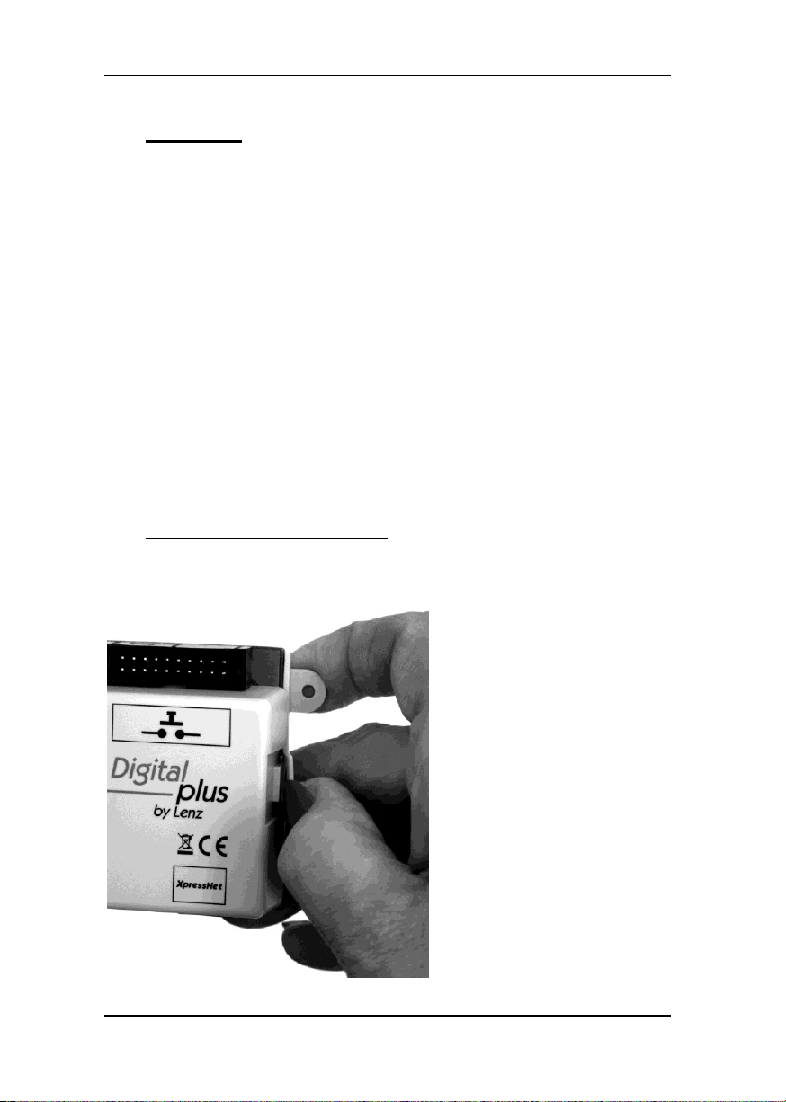
Um diese Einstellungen
vorzunehmen, muss das
Oberteil des Gehäuses
abgenommen werden.
Zum Abnehmen des
Gehäuses biegen Sie die
Laschen des Unterteils
leicht nach außen. Das
Oberteil lässt sich dann
leicht abnehmen.
4 Anzeigen
Am Gerät selbst gibt es zwei LEDs, die über den Betriebszustand
informieren.
LED "Power" (grün)
- leuchtet permanent, wenn Betriebsspannung vorhanden ist und die
Kommunikation mit der Zentrale aufgebaut ist.
- blinkt, wenn sich die Zentrale im Programmiermodus befindet.
LED "XpressNet" (rot)
Diese LED ist im Normalbetrieb aus. Sie blinkt, wenn das Gerät nicht
von der Zentrale adressiert wird, also keine Kommunikation aufgebaut
werden kann. Ursachen dafür können sein:
- Es liegt ein Fehler in der XpressNet-Verkabelung vor.
- Der XpressNet - Anschluss wird hergestellt, während sich die
Zentrale im Programmiermodus befindet.
5 Einstellungen am Gerät
Vor der Inbetriebnahme sollten Sie die Einstellung der
XpressNet-Adresse sowie des Weichenadressbereichs einstellen.
Page 7
7
D
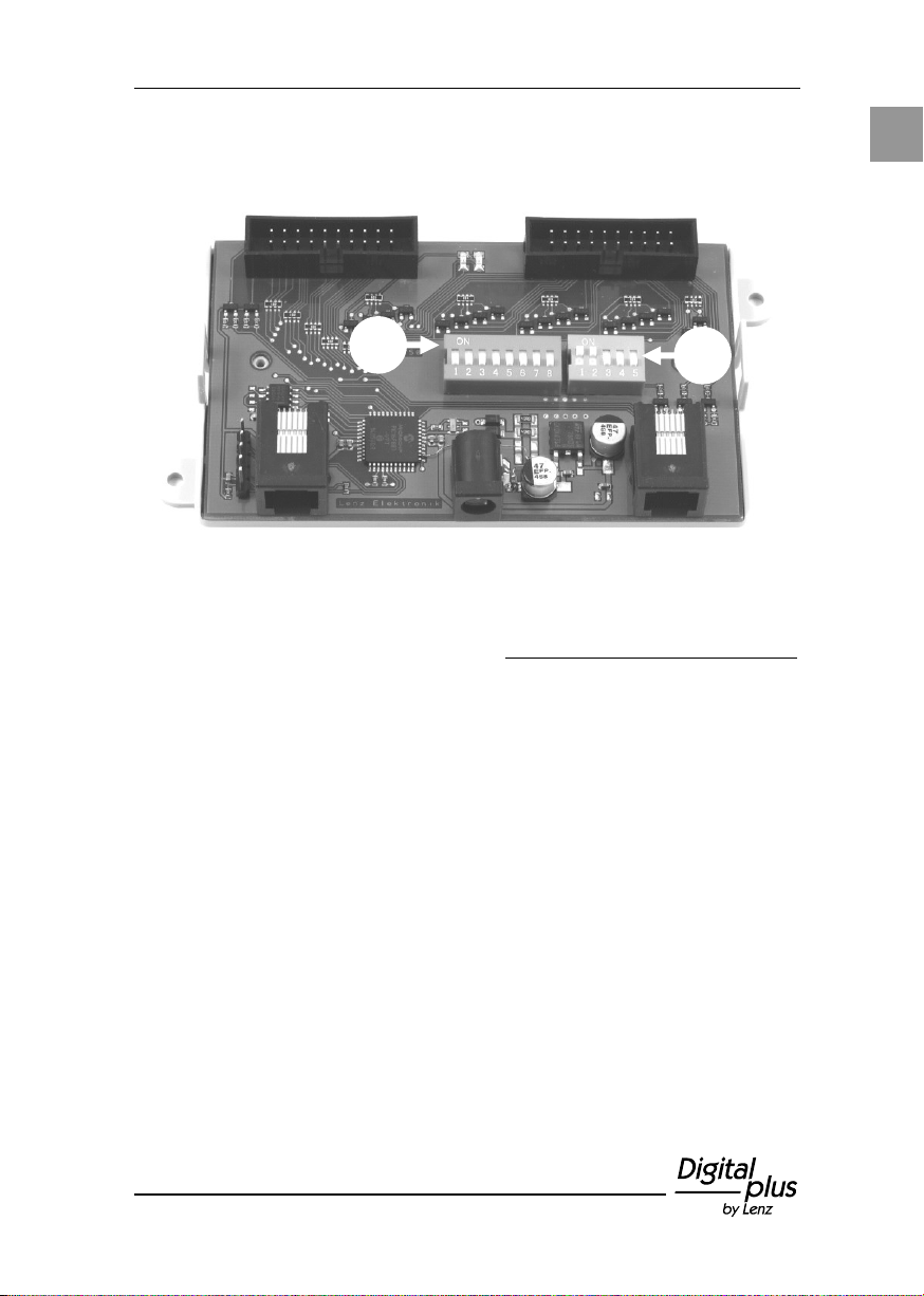
Auf der Leiterplatte des LW150 finden Sie zwei DIP-Schalter
("Mäuseklaviere"), an denen die Einstellungen vorgenommen werden:
5.1 Einstellung des Weichenadressbereichs: DIP-Schalter 1
Das LW150 kann 16 Weichen mit aufeinanderfolgender Adresse
schalten. Wenn Sie mehr als 16 Weichen schalten wollen, verwenden
Sie mehrere LW150. Bitte beachten Sie, dass Sie jedem LW150 eine
eigene XpressNet-Adresse geben müssen, lesen Sie dazu den
Abschnitt "Einstellung der XpressNet Adresse" (S. 11).
Beim Einsatz von zwei oder mehr Modulen schalten Sie mit dem
ersten Modul die Weichen mit den Adressen 1 bis 16, mit dem
zweiten Modul die Weichen mit den Adressen 17 bis 32 und so weiter.
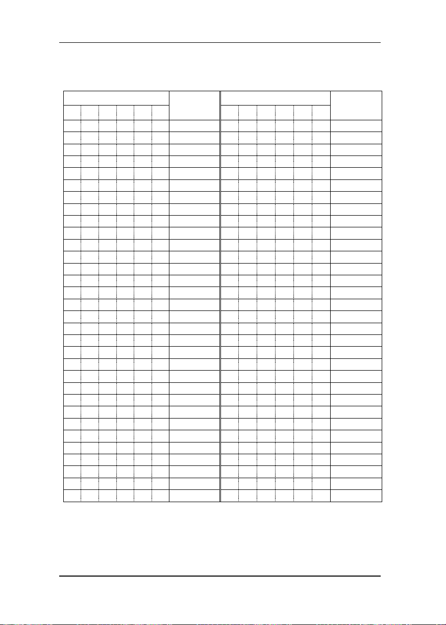
Die Einstellung des Weichenadressbereichs wird an den Schaltern
1 bis 6 wird des DIP-Schalter 1 vorgenommen.
Für die 6 DIP-Schalter steht in der folgenden Tabelle "1" für
Schalterstellung "ON" sowie "0" für Schalterstellung "OFF".
Page 8
8 Information LW150
Nr.
Adress-
bereich
Nr.
Adress-
bereich
1 2 3 4 5 6 1 2 3 4 5
6
0 0 0 0 0 0 1 -16
0 0 0 0 0 1 513 - 528
1 0 0 0 0 0 17 - 32
1 0 0 0 0 1 529 - 544
0 1 0 0 0 0 33 - 48
0 1 0 0 0 1 545 - 560
1 1 0 0 0 0 49 - 64
1 1 0 0 0 1 561 - 576
0 0 1 0 0 0 65 - 80
0 0 1 0 0 1 577 - 592
1 0 1 0 0 0 81 - 96
1 0 1 0 0 1 593 - 608
0 1 1 0 0 0 97 - 112
0 1 1 0 0 1 609 - 624
1 1 1 0 0 0 113 - 128
1 1 1 0 0 1 625 - 640
0 0 0 1 0 0 129 - 144
0 0 0 1 0 1 641 - 656
1 0 0 1 0 0 145 - 160
1 0 0 1 0 1 657 - 672
0 1 0 1 0 0 161 - 176
0 1 0 1 0 1 673 688
1 1 0 1 0 0 177 - 192
1 1 0 1 0 1 689 - 704
0 0 1 1 0 0 193 - 208
0 0 1 1 0 1 705 - 720
1 0 1 1 0 0 209 - 224
1 0 1 1 0 1 721 -736
0 1 1 1 0 0 225 - 240
0 1 1 1 0 1 737 - 752
1 1 1 1 0 0 241 - 256
1 1 1 1 0 1 753 - 768
0 0 0 0 1 0 257 - 272
0 0 0 0 1 1 769 - 784
1 0 0 0 1 0 273 - 288
1 0 0 0 1 1 785 - 800
0 1 0 0 1 0 289 - 304
0 1 0 0 1 1 801 - 816
1 1 0 0 1 0 305 - 320
1 1 0 0 1 1 817 - 832
0 0 1 0 1 0 321 - 336
0 0 1 0 1 1 833 - 848
1 0 1 0 1 0 337 - 352
1 0 1 0 1 1 849 - 864
0 1 1 0 1 0 353 - 368
0 1 1 0 1 1 865 - 880
1 1 1 0 1 0 369 - 384
1 1 1 0 1 1 881 - 896
0 0 0 1 1 0 385 - 400
0 0 0 1 1 1 897 - 912
1 0 0 1 1 0 401 - 416
1 0 0 1 1 1 913 - 928
0 1 0 1 1 0 417 - 432
0 1 0 1 1 1 929 - 944
1 1 0 1 1 0 433 - 448
1 1 0 1 1 1 945 - 960
0 0 1 1 1 0 449 - 464
0 0 1 1 1 1 961 - 976
1 0 1 1 1 0 465 - 480
1 0 1 1 1 1 977 - 992
0 1 1 1 1 0 481 - 496
0 1 1 1 1 1 993 - 1008
1 1 1 1 1 0 497 - 512
1 1 1 1 1 1 1009 - 1024
Tabelle DIP-Schaltereinstellung / Weichenadressbereich
Page 9
9
D
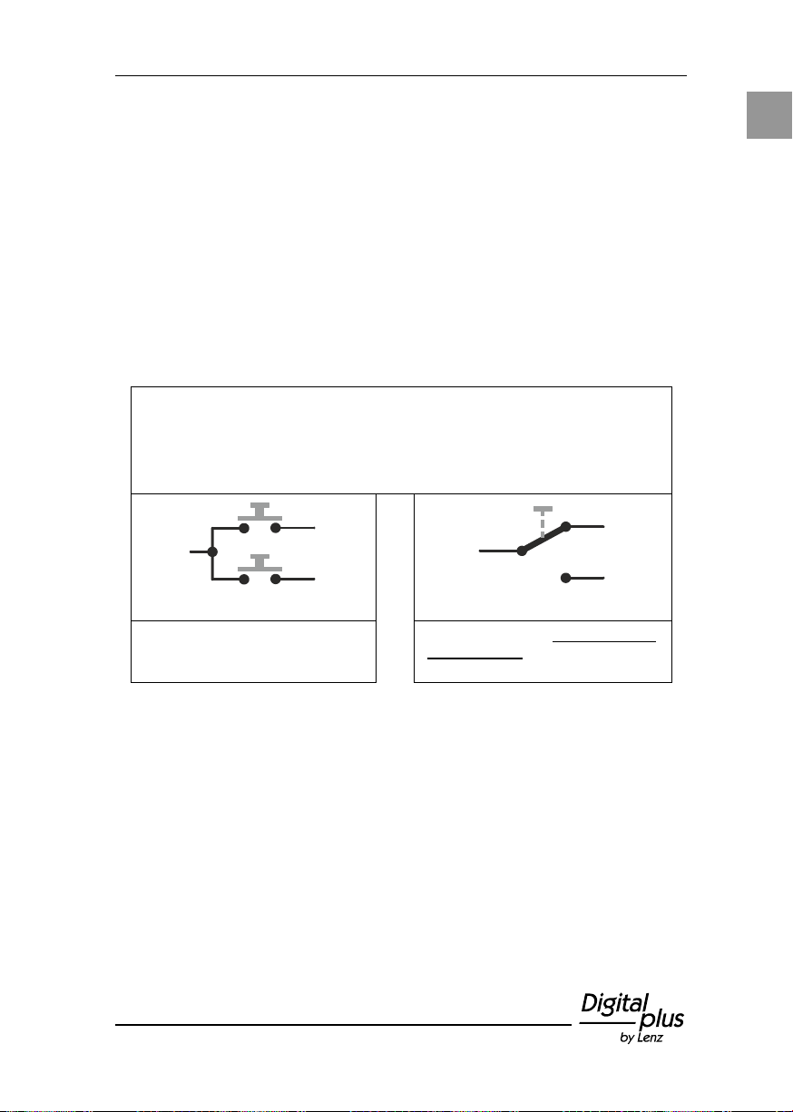
DIP-Schalter 8 = ON (Werkseinstellung)
Das LW150 sorgt dafür, dass die Weichen / Signale gemäß der
im LW150 gespeicherten Daten bzw. Schalterstellung gestellt
werden.
Verwendung von Tastern:
Verwendung von Schaltern:
LW150 sendet die gespeicherten
Zustände als Schaltbefehle an die
Zentrale
LW150 sendet der Schalterstellung
entsprechende Schaltbefehle an die
Zentrale
5.2 Einstellung des Einschaltverhaltens
Mit der Einstellung des Einschaltverhaltens legen Sie fest, ob nach
dem Einschalten des Gerätes der gespeicherte Zustand der
Stellungen von Weichen und Signalen automatisch wieder hergestellt
wird oder nicht.
Die Einstellung der XpressNet-Adresse wird am DIP-Schalter 1 mit
dem Schalter 8 vorgenommen:
Wie genau sich diese Einstellungen auswirken, sehen Sie aus der
folgenden Darstellung. Beachten Sie bitte auch, dass das Verhalten je
nach Verwendung von Tastern oder Schaltern unterschiedlich ist:
Beispiel:
Beim Ausschalten der Anlage ist die Stellung der Weiche 5
"gerade". Nach dem Ausschalten der Anlage wird die Stellung
dieser Weiche per Hand von "gerade" auf "abzweigend" geändert.
Wird die Anlage wieder eingeschaltet, so sendet das LW150 einen
Schaltbefehl an Weiche 5 und stellt die Weiche damit wieder auf
"gerade".
Page 10
10 Information LW150
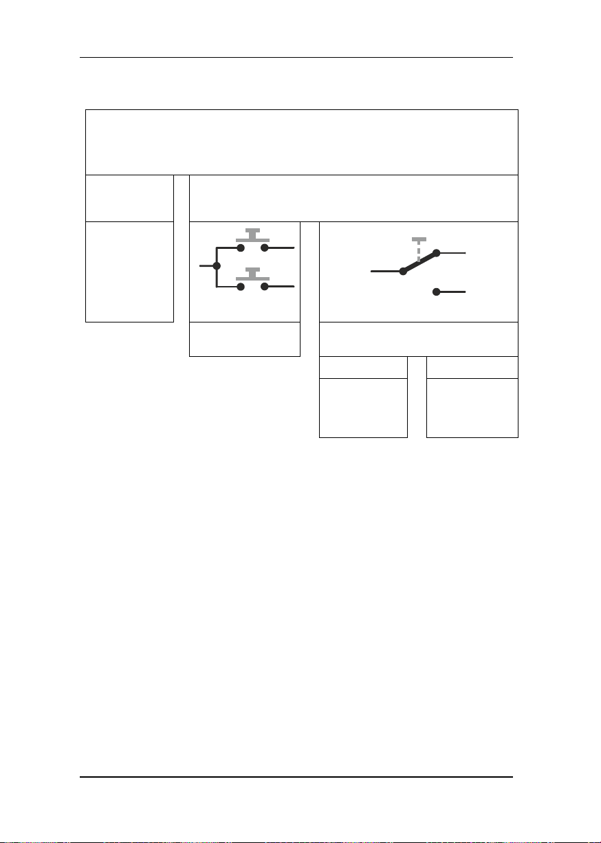
DIP-Schalter 8 = OFF
Das LW150 zeigt nur bei den Weichen die Stellung an, zu denen es
von der Zentrale eine Stellungsmeldung erhalten hat.
Keine
Stellungs-
meldung:
Stellungsmeldung erhalten:
Es erfolgt
keine Anzeige.
Verwendung von
Tastern:
Verwendung von Schaltern:
Stellungsanzeige
leuchtet
Stimmt die Stellungsmeldung mit der
Schalterstellung überein?
JA NEIN
Stellungs-
anzeige
leuchtet
permanent
Stellungs-
anzeige blinkt
Page 11
11
D
Nr.
XpressNet -
Adresse
Nr.
XpressNet -
Adresse
1 2 3 4 5 1 2 3 4
5
1 0 0 0 0 1 1 0 0 0 1
17
0 1 0 0 0 2 0 1 0 0 1
18
1 1 0 0 0 3 1 1 0 0 1
19
0 0 1 0 0
4
0 0 1 0 1
20
1 0 1 0 0 5 1 0 1 0 1
21
0 1 1 0 0 6 0 1 1 0 1
22
1 1 1 0 0 7 1 1 1 0 1
23
0 0 0 1 0 8 0 0 0 1 1
24
1 0 0 1 0 9 1 0 0 1 1
25
0 1 0 1 0
10
0 1 0 1 1
26
1 1 0 1 0
11
1 1 0 1 1
27
0 0 1 1 0
12
0 0 1 1 1
28
1 0 1 1 0
13
1 0 1 1 1
29
0 1 1 1 0
14
0 1 1 1 1
30
1 1 1 1 0
15
1 1 1 1 1
31
0 0 0 0 1
16
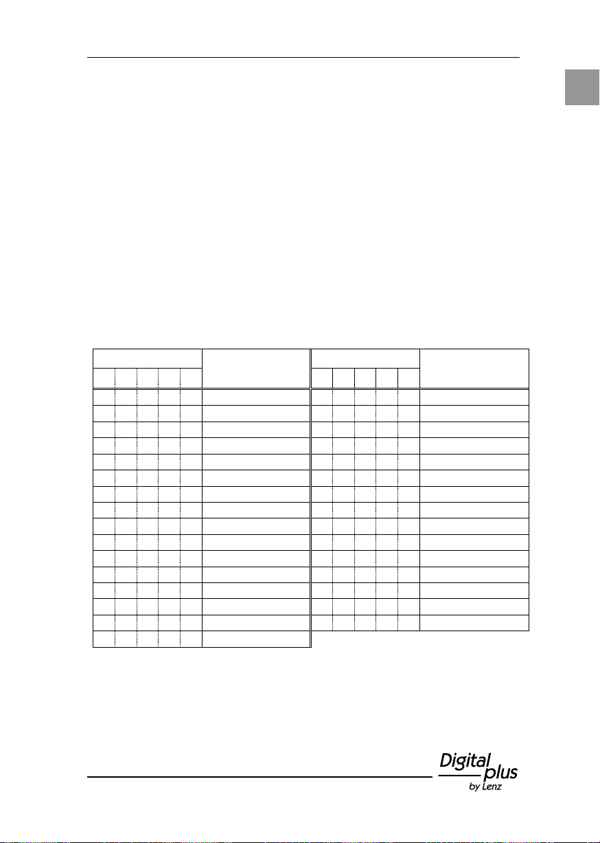
5.3 Einstellung der XpressNet Adresse
Alle am XpressNet angeschlossenen Eingabegeräte müssen zur
korrekten Abwicklung des Informationsaustausches mit der Zentrale
eine eigene Geräteadresse haben. Sie müssen daher sicherstellen,
dass alle angeschlossenen Geräte verschiedene Geräteadressen
haben. Insgesamt können bis zu 31 Geräte an das XpressNet
angeschlossen werden.
Die Einstellung der XpressNet-Adresse wird am DIP-Schalter 2
vorgenommen. Für die Stellung der 5 DIP-Schalter steht in der
folgenden Tabelle
"1" für Schalterstellung "ON" sowie
"0" für Schalterstellung "OFF".
Einstellung am DIP Schalter 2:
Im Auslieferungszustand ist die XpressNet-Adresse 4 eingestellt. Die
Einstellung der Adresse "0" (alle DIP-Schalter "OFF") ist nicht
zulässig, mit dieser Einstellung arbeitet das Gerät nicht.
Page 12
12 Information LW150
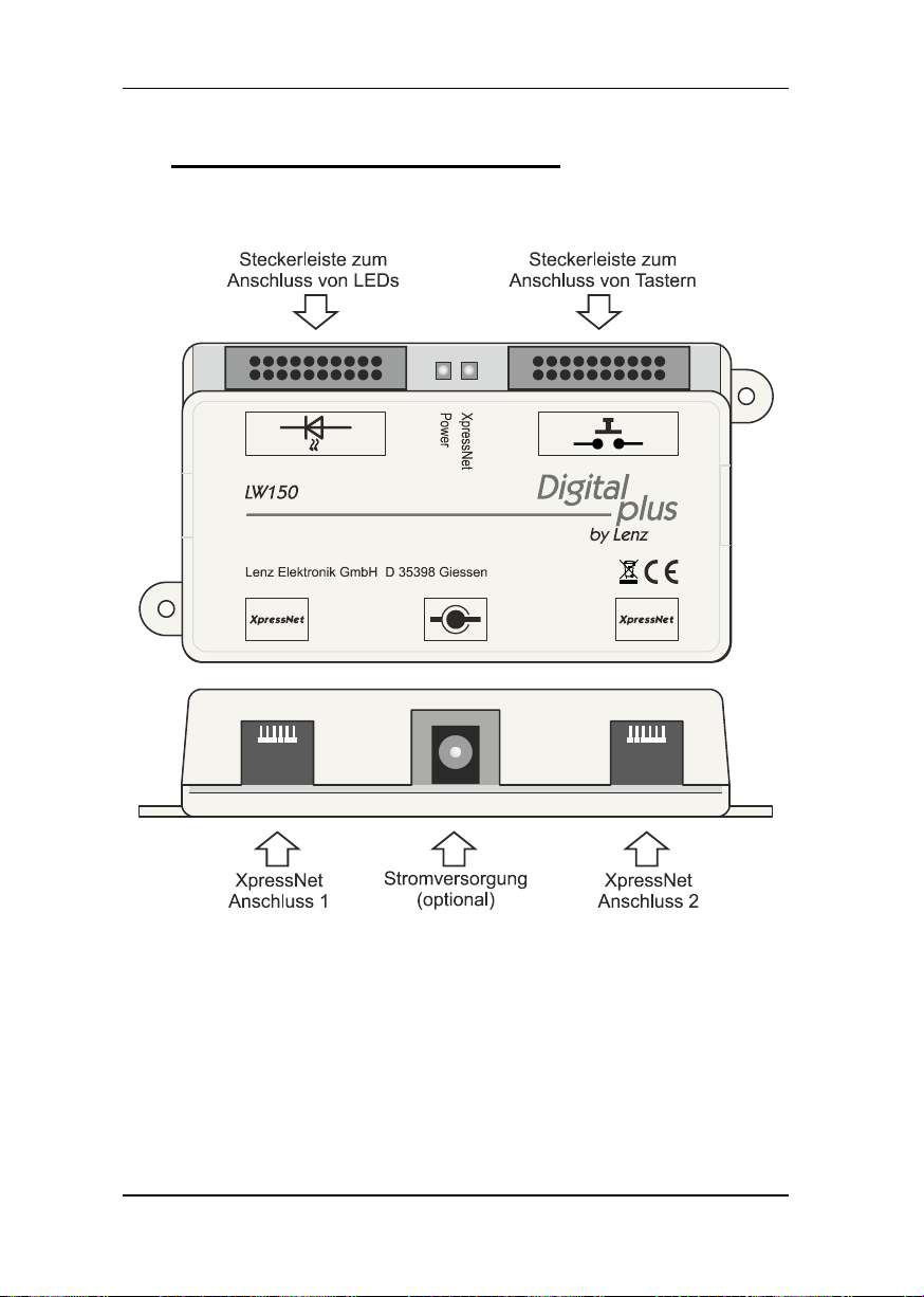
6 Die Anschlüsse in der Übersicht
Abb. 1: Die Anschlüsse des LW150
Page 13
13
D
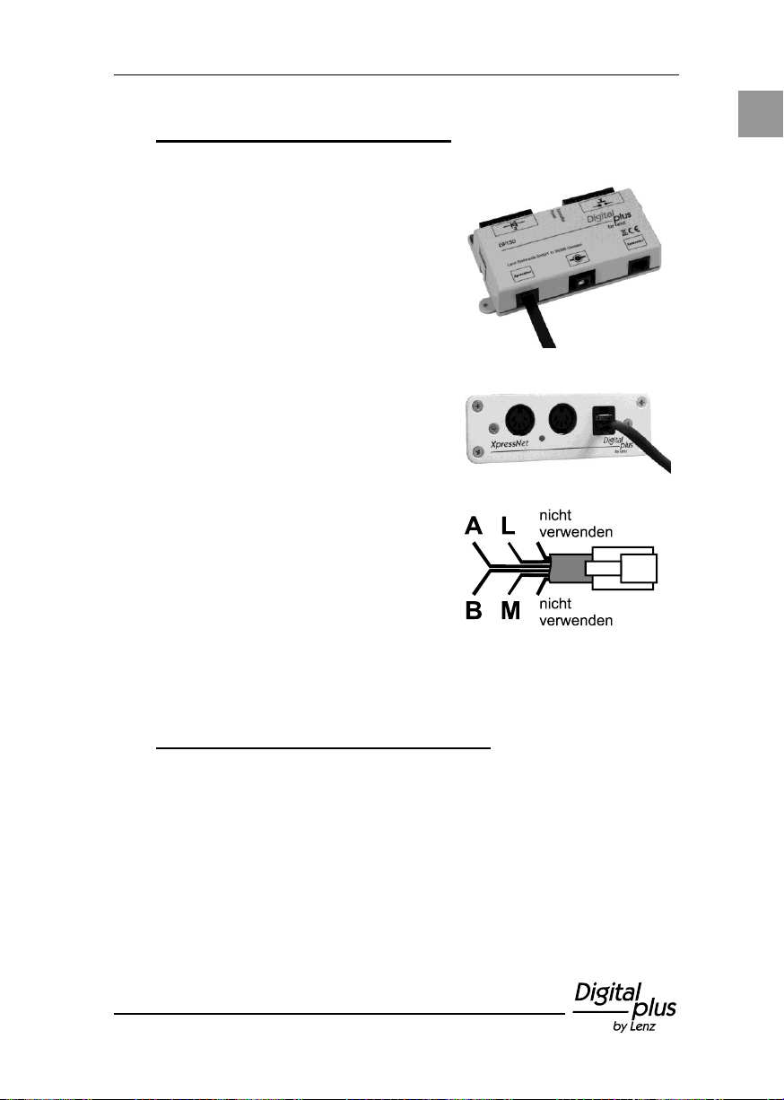
Zum Anschluss an das XpressNet
verwenden Sie das beiliegende Kabel.
Die eine Seite stecken Sie in eine der
beiden Buchsen "XpressNet" des
LW150 (an die zweite Buchse
"XpressNet" können Sie weitere LW150
anschließen).
Die andere Seite des Anschlusskabels
verbinden Sie mit einer Anschlussplatte
LA152.
Wollen Sie das LW150 mit den
Schraubklemmen LMAB einer LZ100
oder LZV100 verbinden, schneiden Sie
das Kabel an geeigneter Stelle durch
und verbinden die Adern mit den
entsprechenden Klemmen der LZ100
bzw. LZV100. Die Pinbelegung sehen
Sie in der Abbildung rechts.
7 Anschluss an das XpressNet
8 Anschluss der Stromversorgung
Der Anschluss der Stromversorgung ist optional und wird nur unter
bestimmten Umständen bei der Verwendung der Stellungsanzeige
benötigt. Hinweise dazu finden Sie im Abschnitt "Optionale
Stromversorgung" (S. 22).
Page 14
14 Information LW150
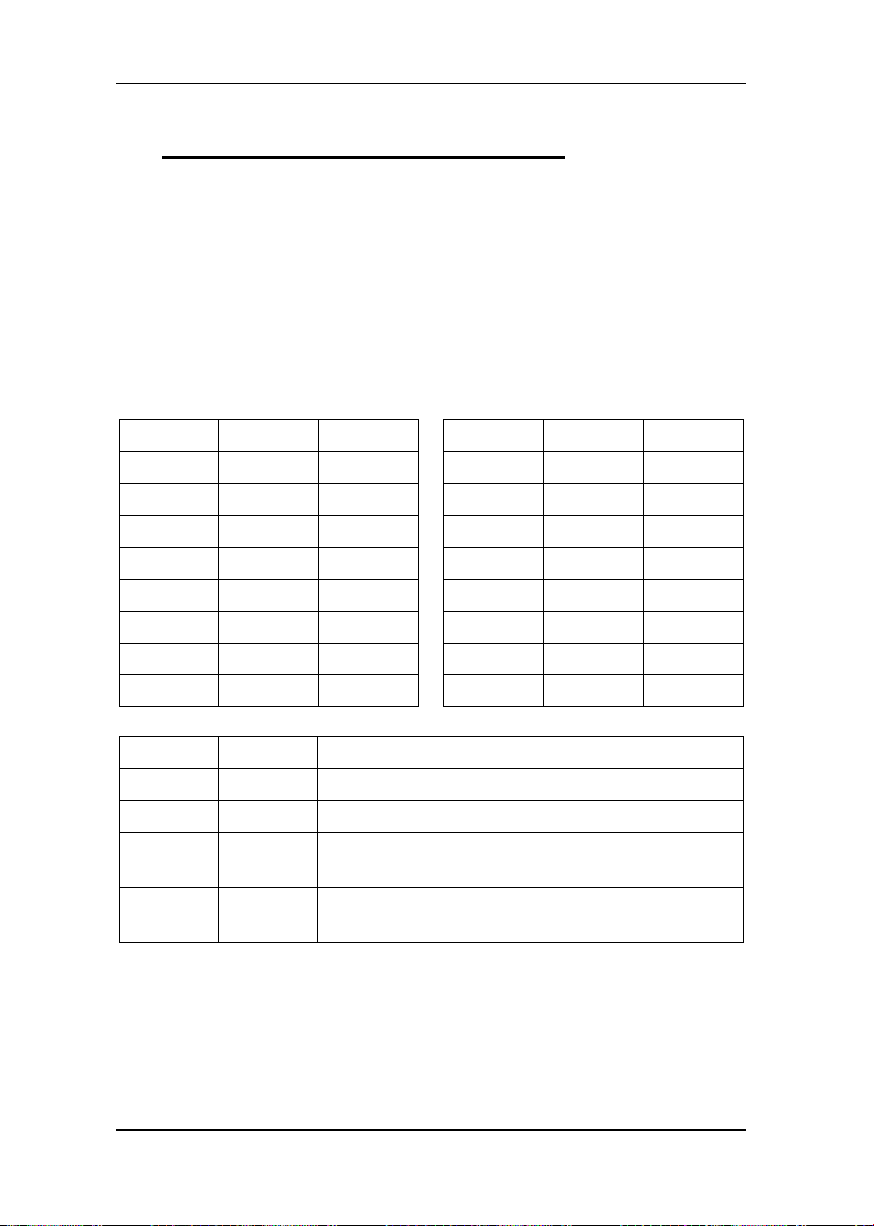
Ader Nr.
Farbe
Weiche
Ader Nr.
Farbe
Weiche
1
schwarz
1 9
rot 9 2
weiß
2 10
braun
10 3 grau
3 11
schwarz
11
4
violett
4 12
weiß
12 5 blau
5 13
grau
13 6 grün
6 14
violett
14 7 gelb
7 15
blau
15
8
orange
8 16
grün
16
Ader Nr.
Farbe
17
gelb
NOTAUS / EIN
18
orange
wird nicht verwendet
19
rot
gemeinsamer Anschluss für Stellung "-" bzw.
"AUS"
20
braun
gemeinsamer Anschluss für Stellung "+"
bzw. "EIN"
9 Anschluss der Taster / der Schalter
Zum Schalten von Weichen, Signalen, Entkupplern und anderen
Zubehörartikel können wahlweise Taster (2 Stück pro Weiche) oder
Kippschalter (Umschalter ohne Mittelstellung) verwendet werden.
Dabei können Tasterpaare und Kippschalter durchaus gemischt
verwendet werden, jedoch nicht gleichzeitig (parallel) für die selbe
Weiche.
Zum Anschluss der Taster / Kippschalter wird das dem LW150
beiliegende 20-adrige Kabel verwendet. Zur leichteren Orientierung
sind die einzelnen Adern des Kabels farbig codiert:
Page 15
15
D
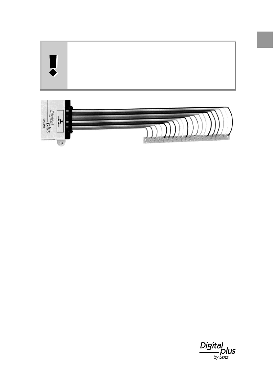
Tipp!
Am einfachsten erledigen Sie die Verkabelung, indem Sie
die Enden des Anschlusskabels für die Taster an einer
handelsüblichen Lötleiste anlöten. Von hier aus können
Sie dann bequem die weitere Verkabelung zu den Tastern
/ Schaltern vornehmen.
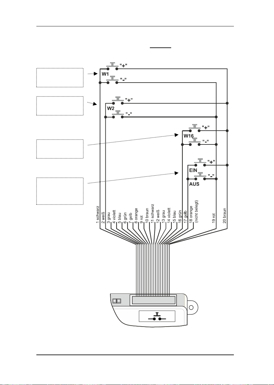
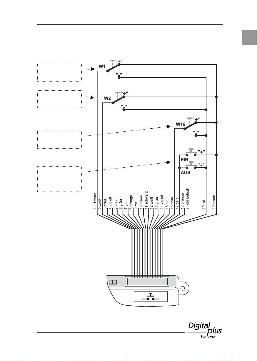
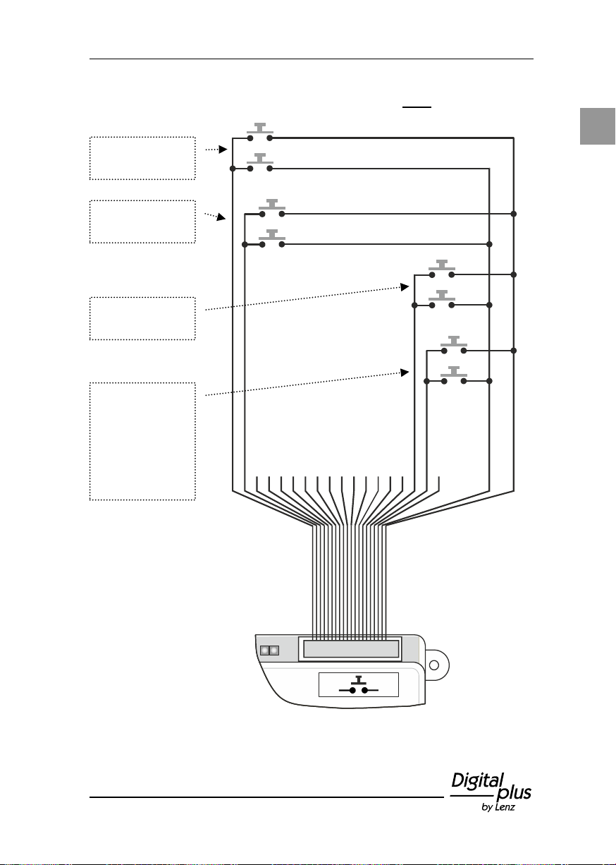
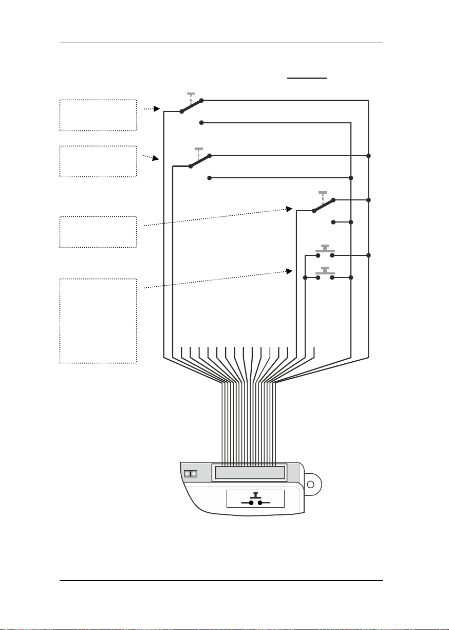
An die Adern 1 bis 16 werden die Tasterpaare / Kippschalter für die
Weichen 1 bis 16 angeschlossen.
An die Ader Nr. 17 können ein Taster für die "NOTAUS"-Funktion des
Digital plus Systems, sowie ein Taster für das Auflösen des Notaus
angeschlossen werden. Der Anschluss dieser Tasten ist optional. Für
diese Funktion dürfen keine Schalter verwendet werden!
Page 16
16 Information LW150
Tastenpaar für
Weiche 1
Tastenpaar für
Weiche 2
Tastenpaar für
Weiche 16
…und so
weiter bis zum
Tastenpaar
NOTAUS / EIN
(optional)
Das Prinzip des Anschlusses von Tastern zeigt die folgende
Abbildung:
Page 17
17
D
Kippschalter
für Weiche 1
Kippschalter
für Weiche 2
Kippschalter
für Weiche 16
…und so
weiter bis zum
Tastenpaar
NOTAUS / EIN
(optional)
Das Prinzip des Anschlusses von Schaltern zeigt die folgende
Abbildung:
Page 18
18 Information LW150
Die Anzeige der Weichenstellung setzt die Verwendung
einer LZ/LZV100 voraus. Die echte Rückmeldung der
Weichenstellung mit den Schaltempfängern LS100 setzt
endabgeschaltete Weichenantriebe oder entsprechende
potentialfreie Meldekontakte am Antrieb voraus.
Es dürfen keine Glühlampen an das LW150
angeschlossen werden!
Wenn Sie andere LEDs einsetzen wollen, so verwenden
Sie so genannte "low current" Typen. Ein Vorwiderstand
ist nicht nötig, dieser ist bereits im Gerät integriert
(1kOhm). Die Spannung an den Ausgängen für die LEDs
beträgt 5V.
Bei der Verwendung von Kippschaltern (statt Tastern)
blinkt die LED, wenn die Stellung des Schalters nicht mit
der von der Zentrale mitgeteilten Weichenstellung
übereinstimmt.
10 Anzeige der Weichen- / Signalstellung
Zur Anzeige der Stellung von Weichen und Signalen wird das
Ergänzungs-Set (Art.Nr. 80145) verwendet. Es besteht aus einem
20-adrigen Anschlusskabel und 32 gelben Leuchtdioden (LEDs).
Bei Inbetriebnahme des Digital plus Systems reagiert das LW150 je
nach Einstellung des DIP-Schalters 8 (vgl. Abschnitt "Einstellung des
Einschaltverhaltens" S. 9). Wird während des Betriebs die Stellung
einer Weiche z.B. von einem Handregler verändert, so ändert sich
auch die Anzeige des LW150. Bei der Verwendung der
rückmeldefähigen Schaltempfänger LS100 wird auch eine
Veränderung der Weichenstellung per Hand angezeigt (echte
Rückmeldung), korrekte Verdrahtung der betreffenden
Weichenantriebe vorausgesetzt.
Wie beim Anschluss der Taster empfehlen wir auch beim Anschluss
der LEDs die abisolierten Adern des Anschlusskabels für die LEDs an
eine handelsüblichen Lötleiste anzulöten. Zur leichteren Orientierung
sind die einzelnen Adern des Kabels farbig codiert.
Page 19
19
D
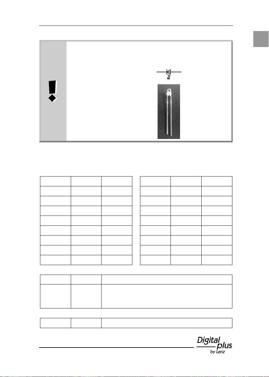
LEDs müssen "richtig herum" angeschlossen werden. Die
beiden Anschlüsse der LEDs werden mit "Kathode" und
"Anode" bezeichnet:
Symbol im
Verdrahtungsplan
Kathode
Anode
Ansicht von der
Seite
kurzer
Draht
langer Draht
Ader Nr.
Farbe
Weiche
Ader Nr.
Farbe
Weiche
1
schwarz
1 9
rot 9 2
weiß
2 10
braun
10 3 grau
3 11
schwarz
11
4
violett
4 12
weiß
12 5 blau
5 13
grau
13 6 grün
6 14
violett
14 7 gelb
7 15
blau
15
8
orange
8 16
grün
16
Ader Nr.
Farbe
17
gelb
An diese Ader können die Kathoden zweier
LEDs zur Anzeige des Zustandes AUS / EIN
angeschlossen werden.
18
orange
wird nicht verwendet
Folgende Tabelle zeigt die Zuordnung der Ader zum
Kathodenanschluss der LED zur korrespondierenden Weiche:
Page 20
20 Information LW150
Ader Nr.
Farbe
19
rot
gemeinsamer Anschluss der Anode der
LEDs für Stellung "-" bzw. "AUS"
20
braun
gemeinsamer Anschluss der Anode der
LEDs für Stellung "+" bzw. "EIN"
Für den Anodenanschluss (langer Draht) der LEDs gilt folgende
Tabelle:
Page 21
21
D
LED-Paar für
Weiche 1
LED-Paar für
Weiche 2
LED-Paar für
Weiche 16
…und so
weiter bis zum
LED-Paar
NOTAUS / EIN
(optional)
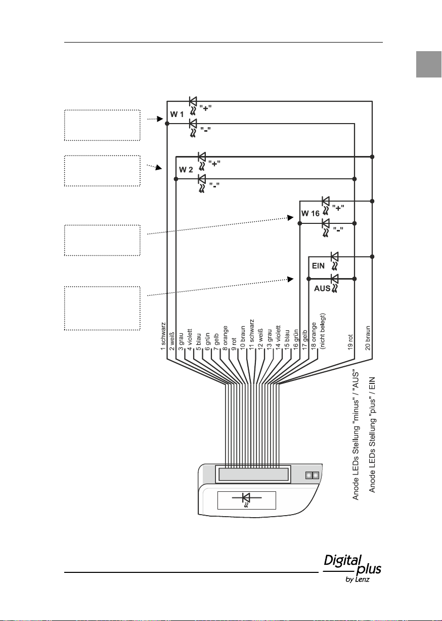
Das Prinzip des Anschlusses der Leuchtdioden (LEDs) zeigt die
folgende Abbildung:
Page 22
22 Information LW150
Bei der hier beschriebenen Stromversorgung handelt es
sich nicht um die Versorgung der Gleisanlage (Anschluss
J&K). Es handelt sich ausschließlich um die Geräte am
XpressNet sowie an den Anschlüssen CDE und RS.
Maximal kann die LZ/LZV100 300mA für diese Geräte zur
Verfügung stellen.
Gerät
Anschluss
Stromaufnahme
Handregler LH101
XpressNet (LMAB)
22mA
Handregler LH100
XpressNet (LMAB)
28mA
Handregler LH90
XpressNet (LMAB)
18mA
Handregler LH01
XpressNet (LMAB)
30mA
Tastenmodul LW150
XpressNet (LMAB)
18mA (ohne LEDs)
Tastenmodul LW150
XpressNet (LMAB)
39mA (mit LEDs)
Interface
XpressNet (LMAB)
21mA
Schaltempfänger LS100
RS
1,5mA
Rückmelder LR101
RS
1,5mA
Verstärker LV101
CDE
10mA
10.1 Optionale Stromversorgung
Die optionale Stromversorgung wird nur dann benötigt, wenn die
Stromversorgung der Zentrale nicht ausreicht, an sie angeschlossene
Geräte zu versorgen. Zu diesen Geräten zählen XpressNet - Geräte
(Handregler, Interface, Tastenmodul), aber auch rückmeldefähige
Decoder (Rückmelder und Schaltempfänger mit Rückmeldung) und
Verstärker.
Wenn Sie ausrechnen wollen, wie groß die Stromaufnahme der von
Ihnen bereits verwendeten Geräte ist, können Sie diese Tabelle zu
Grunde legen:
Sollte die Versorgung der Zentrale nicht mehr ausreichend sein, so
erkennen Sie dies daran, dass die grüne LED des Tastenmoduls aus
bleibt. In diesem Fall verwenden Sie zur Stromversorgung des LW150
das Netzteil 26160.
Page 23
23
D
Fehler
Ursache
Beseitigung
Keine Funktion (grüne LED
aus)
Keine Betriebsspannung
oder XpressNet nicht aktiv
Überprüfen Sie die
Verdrahtung des XpressNet
Vergewissern Sie sich,
dass die XpressNet
Stromversorgung nicht
überlastet ist (S. 22).
Weichen schalten nicht,
Anzeige wechselt aber
Weichenadressbereich
falsch eingestellt
DIP-Schalter für den
Adressbereich korrekt
einstellen (S. 7).
Rote LED blinkt
Kommunikationsstörung
zwischen Zentrale und
LW150
Überprüfen Sie die
Einstellung der XpressNet
Adresse (S. 11) und
starten Sie das System
neu.
LEDs zur Stellungsanzeige
leuchten nicht
Verpolungs- oder
Verdrahtungsfehler beim
Anschluss der LEDs
Kontrollieren Sie
Verdrahtung und Polarität
der LEDs (S. 19)
11 Hilfe bei Störungen
Page 24

24 Information SET02
Information LW150
Art. Nr. / Art. no. / Art. n° 25150
Page 25

25
E
Content
1 Welcome! ...................................................................................... 26
2 Important advice, please read first! .............................................. 27
3 What is the purpose of the LW150? ............................................. 27
3.1 Technical data: ...................................................................... 28
4 Indicators ...................................................................................... 28
5 Device settings ............................................................................. 29
5.1 Settings the point address range: DIP switch 1 ..................... 30
5.2 Setting the startup characteristics ......................................... 32
5.3 Setting the XpressNet address .............................................. 34
6 Overview of connections ............................................................... 35
7 Connection to the XpressNet ........................................................ 36
8 Connection to the power supply ................................................... 36
9 Connecting the keys / switches .................................................... 37
10 Indicating the setting of points / signals ........................................ 41
10.1 Optional power supply ........................................................... 44
11 Help in case of malfunction ........................................................... 45
Digital plus manufacturer's warranty
Digital plus products of Lenz Elektronik GmbH are characterized by outstanding
quality. Therefore we grant you as consumer a 6-year manufacturer’s warranty on
these items from date of purchase of the product. The guarantee applies throughout
Europe.
In the case of warranty, please contact Lenz Elektronik GmbH to return the
defective device including proof of purchase.
In case of warranty Lenz Elektronik GmbH bears the costs for repair and return
shipment of the defective device. Based on the free choice of Lenz Elektronik
GmbH either a free repair or an exchange of the device will be carried out. Damage
caused by wear, normal use or improper use of the equipment is excluded from the
warranty. The guarantee therefore only applies if the product is handled properly.
B-stock and refurbished articles are excluded from the manufacturer's warranty.
The guarantee supplements the statutory warranty rights. There is no limitation of
the legal warranty claim by the manufacturer's warranty.
Page 26

26 Information LW150
Mail address:
Lenz Elektronik GmbH
Vogelsang 14
D-35398 Giessen
Phone:
++49 (0) 6403 900 133
A recorded message will inform
you of our availability
Fax:
++49 (0) 6403 900 155
Email:
1 Welcome!
We are glad that you have decided to acquire the
Digital plus by Lenz® key module LW150.
The purpose of this operating manual is to explain the use of the
LW150. If you still have questions after reading this manual, please
contact us. We will be happy to help you. There are four different
ways of contacting Lenz Elektronik GmbH:
If you encounter any problems with the LW150, please contact us,
providing a problem description as well as the following information:
Version number of the command station used (LZV100 or LZ100).
Designation, version number and service number and Xpress Net
address of all connected XpressNet devices.
This will help our service department solve the problem. Thank you.
All present?
Please check if all components have been delivered:
LW150 device
Operating manual (this brochure)
Connecting cable for the XpressNet
Connecting cables for the keys
If any component is missing, please ask your specialist supplier for a
subsequent delivery.
Page 27
27
E
Warning!
Do not leave your model railway system unsupervised
during operation! The possible heating of components
during an unnoticed short-circuit may create a fire risk!
2 Important advice, please read first!
The LW150 is a component of the Digital plus by Lenz® system and
was submitted to intensive testing before delivery. Lenz Elektronik
GmbH guarantees fault-free operation if you follow the advice below:
The LW150 may only be operated with Digital plus by Lenz® system
components. Any use other than that described in this operating
manual is not permitted. All guarantees will be void if the LW150 is
used inappropriately. Connect your LW150 only to devices that are
designated for such connection. This operating manual will tell you
which devices are suitable. Do not expose the LW150 to damp or
direct sunlight.
3 What is the purpose of the LW150?
The key module LW150 is an input device for the Digital plus system.
It serves to control accessories (points, signals, decouplers etc.)
connected to switch decoders in the Digital plus system. Each key
module serves to set a group of 16 points (or signals etc.) by means
of keys or switches. Thus, the LW150 facilitates the setting up of a
track control for use at the Digital plus system. You can use several
key modules LW150 simultaneously. When using two or more
modules, the first module is used to switch point addresses 1 to 16,
the second to switch point addresses 17 to 32 etc.
You can also opt to connect two keys to the LW150 to make use of
the "NOTAUS" (emergency shutdown) function of the Digital plus
system. This will enable you to stop all locomotives on the layout
using the track control in case of an emergency.
Page 28

28 Information LW150
Point addresses
A total of 1024 points, signals, decouplers etc. can be
switched in the Digital system using switch decoders (LS100,
LS150).
Connecting keys
and switches
Connect keys or switches to the LW150 to operate the points.
2 keys or 1 single double-throw switch is required for each
point.
XpressNet address
Each key module LW150 has its own XpressNet address
which is set at a DIP switch. If more than one LW150 is
connected, a different XpressNet address must be set at each
device. You can connect up to 31 devices to the XpressNet.
Automatic
signalling of
settings (switch
commands)
Automatic signalling of settings is also done for points (or
signals) that are not connected to feedback-enabled switch
decoders. The last given switch command is communicated
to all XpressNet devices. Thus, the LW150 can also indicate
the settings of these points and signals.
Data storage
When shutting down, the LW150 stores the point settings.
Depending on the device setting, this stored setting is
automatically restored during startup.
Power supply
(input voltage)
Under certain conditions, the LW150 requires a separate
power supply. More information is available in the
corresponding section of this operating manual.
Dimensions
W 120 mm x H 25 mm x 60 mm
3.1 Technical data:
4 Indicators
The device has two LEDs that indicate the operating mode.
LED "Power" (green)
- Shines permanently when operating voltage is applied and
communication established with the command station.
- Flashes when the command station is in programming mode.
LED "XpressNet" (red)
In standard operation, this LED is switched off. It flashes when the
device is not addressed by the command station, i.e. no
communication can be established. Possible causes are:
- There is an error in the XpressNet wiring.
- The XpressNet connection is being established while the
command station is in programming mode.
Page 29
29
E
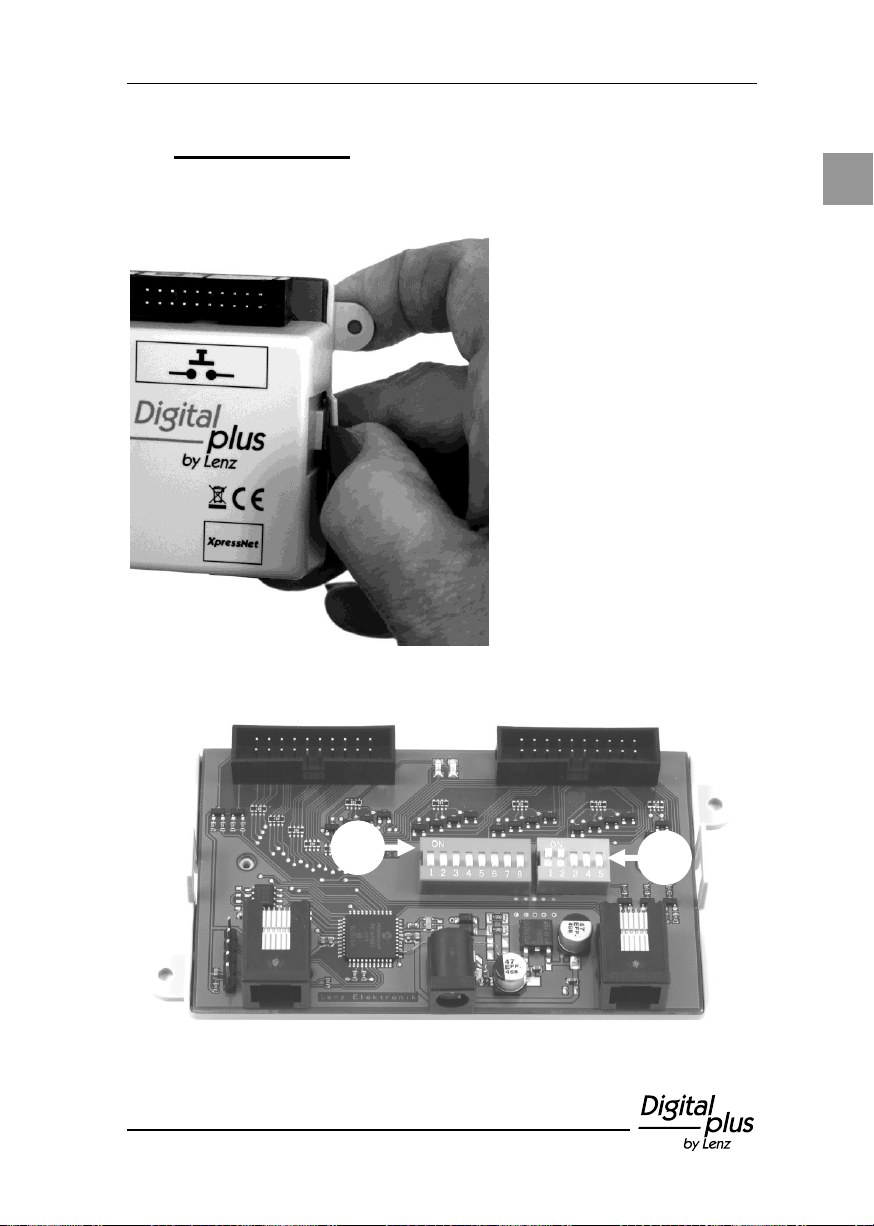
To effect these settings,
remove the upper part of
the housing.
To do so, slightly bend the
ears of the lower part of
the housing to the outside.
The upper part can now
be easily removed.
5 Device settings
Before initializing the device, you should set the XpressNet address
as well as the point address range.
The circuit board of the LW150 features two DIP switches to effect the
settings:
Page 30

30 Information LW150
5.1 Setting the point address range: DIP switch 1
The LW150 can switch 16 points with consecutive addresses. To
switch more than 16 points, you will have to use two or more modules
LW150. Please note that you must assign a separate XpressNet
address to each LW150. For more information, read the section
"Setting the XpressNet address" (p. 34).
When using two or more modules, the first module switches point
addresses 1 to 16, the second point addresses 17 to 32 etc.
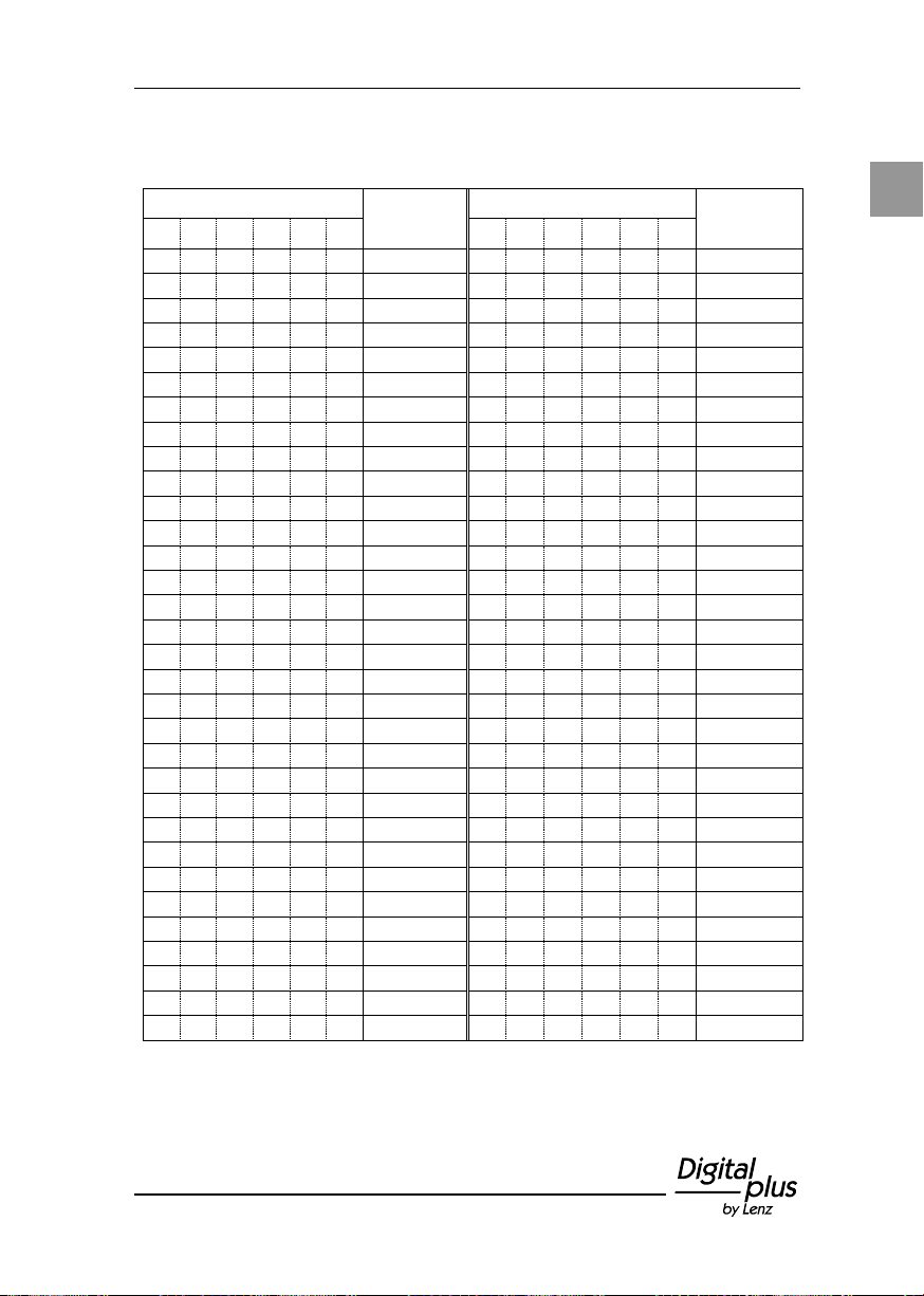
The point address range is set with switches 1 to 6 at DIP switch 1.
For the six DIP switches, in the following table, "1" stands for switch
position "ON" and "0" for switch position "OFF".
Page 31
31
E
No.
Address
range
No.
Address
range
1 2 3 4 5 6 1 2 3 4 5
6
0 0 0 0 0 0 1 -16
0 0 0 0 0 1 513 - 528
1 0 0 0 0 0 17 - 32
1 0 0 0 0 1 529 - 544
0 1 0 0 0 0 33 - 48
0 1 0 0 0 1 545 - 560
1 1 0 0 0 0 49 - 64
1 1 0 0 0 1 561 - 576
0 0 1 0 0 0 65 - 80
0 0 1 0 0 1 577 - 592
1 0 1 0 0 0 81 - 96
1 0 1 0 0 1 593 - 608
0 1 1 0 0 0 97 - 112
0 1 1 0 0 1 609 - 624
1 1 1 0 0 0 113 - 128
1 1 1 0 0 1 625 - 640
0 0 0 1 0 0 129 - 144
0 0 0 1 0 1 641 - 656
1 0 0 1 0 0 145 - 160
1 0 0 1 0 1 657 - 672
0 1 0 1 0 0 161 - 176
0 1 0 1 0 1 673 688
1 1 0 1 0 0 177 - 192
1 1 0 1 0 1 689 - 704
0 0 1 1 0 0 193 - 208
0 0 1 1 0 1 705 - 720
1 0 1 1 0 0 209 - 224
1 0 1 1 0 1 721 -736
0 1 1 1 0 0 225 - 240
0 1 1 1 0 1 737 - 752
1 1 1 1 0 0 241 - 256
1 1 1 1 0 1 753 - 768
0 0 0 0 1 0 257 - 272
0 0 0 0 1 1 769 - 784
1 0 0 0 1 0 273 - 288
1 0 0 0 1 1 785 - 800
0 1 0 0 1 0 289 - 304
0 1 0 0 1 1 801 - 816
1 1 0 0 1 0 305 - 320
1 1 0 0 1 1 817 - 832
0 0 1 0 1 0 321 - 336
0 0 1 0 1 1 833 - 848
1 0 1 0 1 0 337 - 352
1 0 1 0 1 1 849 - 864
0 1 1 0 1 0 353 - 368
0 1 1 0 1 1 865 - 880
1 1 1 0 1 0 369 - 384
1 1 1 0 1 1 881 - 896
0 0 0 1 1 0 385 - 400
0 0 0 1 1 1 897 - 912
1 0 0 1 1 0 401 - 416
1 0 0 1 1 1 913 - 928
0 1 0 1 1 0 417 - 432
0 1 0 1 1 1 929 - 944
1 1 0 1 1 0 433 - 448
1 1 0 1 1 1 945 - 960
0 0 1 1 1 0 449 - 464
0 0 1 1 1 1 961 - 976
1 0 1 1 1 0 465 - 480
1 0 1 1 1 1 977 - 992
0 1 1 1 1 0 481 - 496
0 1 1 1 1 1 993 - 1008
1 1 1 1 1 0 497 - 512
1 1 1 1 1 1 1009 - 1024
Table DIP switch setting / Point address range
Page 32
32 Information LW150
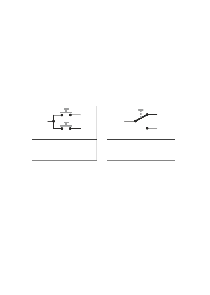
DIP switch 8 = ON (factory setting)
The LW150 ensures that points / signals are set in accordance
with the data stored in the LW150 or the switch setting.
Use of keys:
Use of switches:
The LW150 sends the stored
settings as switch commands to
the command station
The LW150 sends switch
commands corresponding to the
switch setting to the command
station
5.2 Setting the startup characteristics
The startup characteristics determine if the stored settings of points
and signals are automatically restored during startup or not.
The XpressNet address is set with switch 8 at DIP switch 1:
The results of these settings are shown in the following illustrations.
Please note that the behaviour differs depending on whether keys or
switches are used:
Example:
When shutting down the layout, point 5 is set to "straight". After
shutdown, the setting of this point is changed manually from
"straight" to "branching off". During startup, the LW150 will send a
switch command to point 5 and reset the point to "straight".
Page 33
33
E
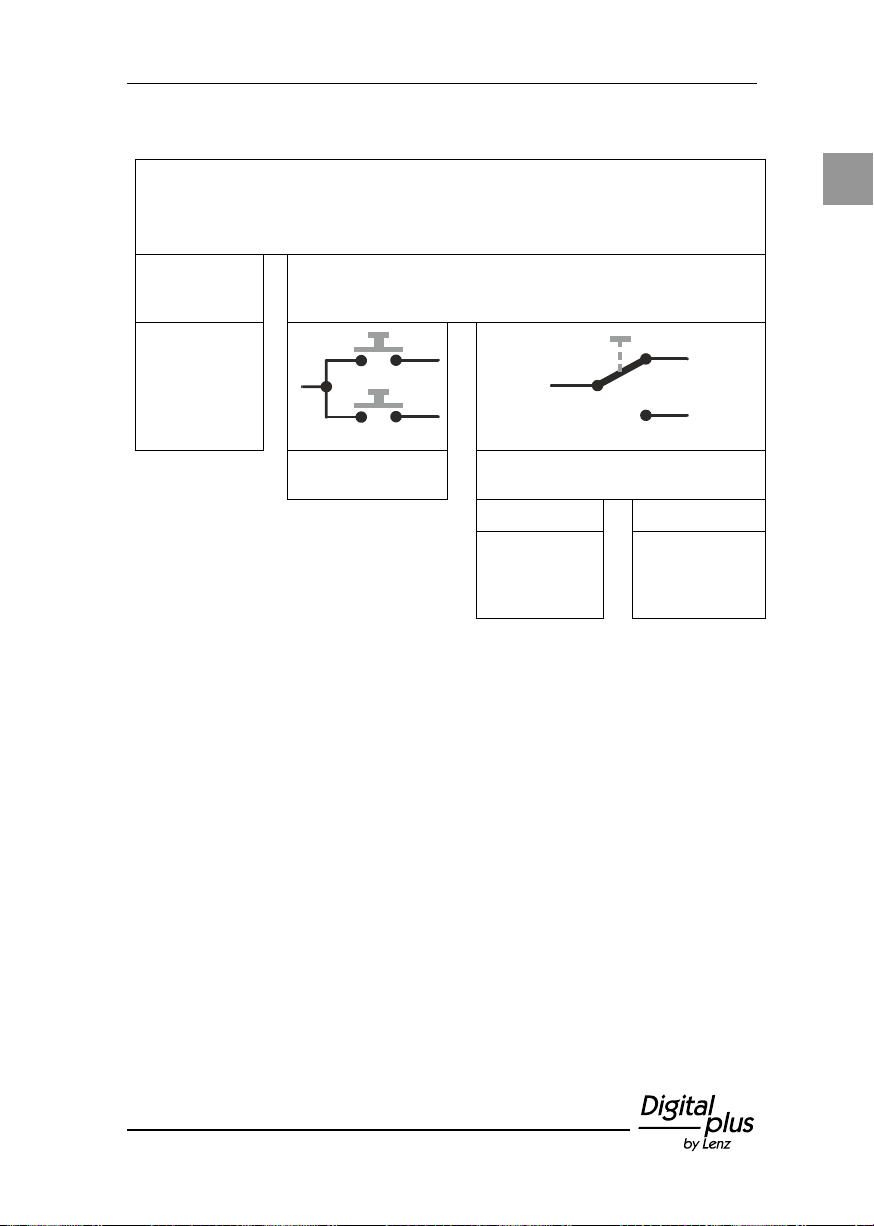
DIP switch 8 = OFF
The LW150 only shows the settings of points whose status
information it has received from the command station.
Status
information not
received:
Status information received:
No indication.
Use of keys:
Use of switches:
Status indicator
shines
Does the status information
correspond to the switch position?
YES NO
Status
indicator
shines
permanently
Status indicator
flashes
Page 34
34 Information LW150
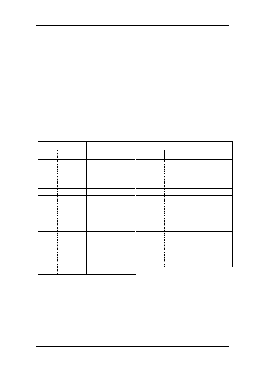
No.
XpressNet
address
No.
XpressNet
address
1 2 3 4 5 1 2 3 4
5
1 0 0 0 0 1 1 0 0 0 1
17
0 1 0 0 0 2 0 1 0 0 1
18
1 1 0 0 0 3 1 1 0 0 1
19
0 0 1 0 0
4
0 0 1 0 1
20
1 0 1 0 0 5 1 0 1 0 1
21
0 1 1 0 0 6 0 1 1 0 1
22
1 1 1 0 0 7 1 1 1 0 1
23
0 0 0 1 0 8 0 0 0 1 1
24
1 0 0 1 0 9 1 0 0 1 1
25
0 1 0 1 0
10
0 1 0 1 1
26
1 1 0 1 0
11
1 1 0 1 1
27
0 0 1 1 0
12
0 0 1 1 1
28
1 0 1 1 0
13
1 0 1 1 1
29
0 1 1 1 0
14
0 1 1 1 1
30
1 1 1 1 0
15
1 1 1 1 1
31
0 0 0 0 1
16
5.3 Setting the XpressNet address
For a fault-free exchange of information with the command station,
each input device connected to the XpressNet must have its own
device address. You must ensure that all connected devices have
different addresses. Up to 31 devices can be connected to the
XpressNet.
The XpressNet address is set at DIP switch 2. For the five DIP
switches, in the following table
"1" stands for switch position "ON" and
"0" for switch position "OFF".
Setting at DIP switch 2:
Ex-factory, XpressNet address 4 is set. Setting address "0" (all DIP
switches "OFF") is not permitted (The device will not work with this
setting).
Page 35
35
E
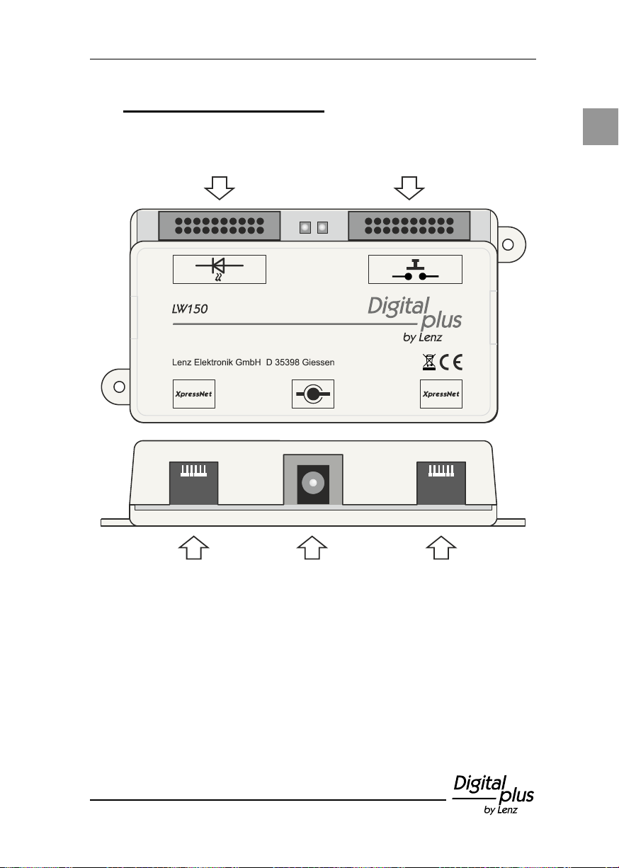
Power
XpressNet
Connection plug board
to connect LEDs
XpressNet
connection 1
power supply
(optional)
XpressNet
connection 2
Connection plug board
to connect keys
6 Overview of connections
Fig. 2: The connections of the LW150
Page 36
36 Information LW150
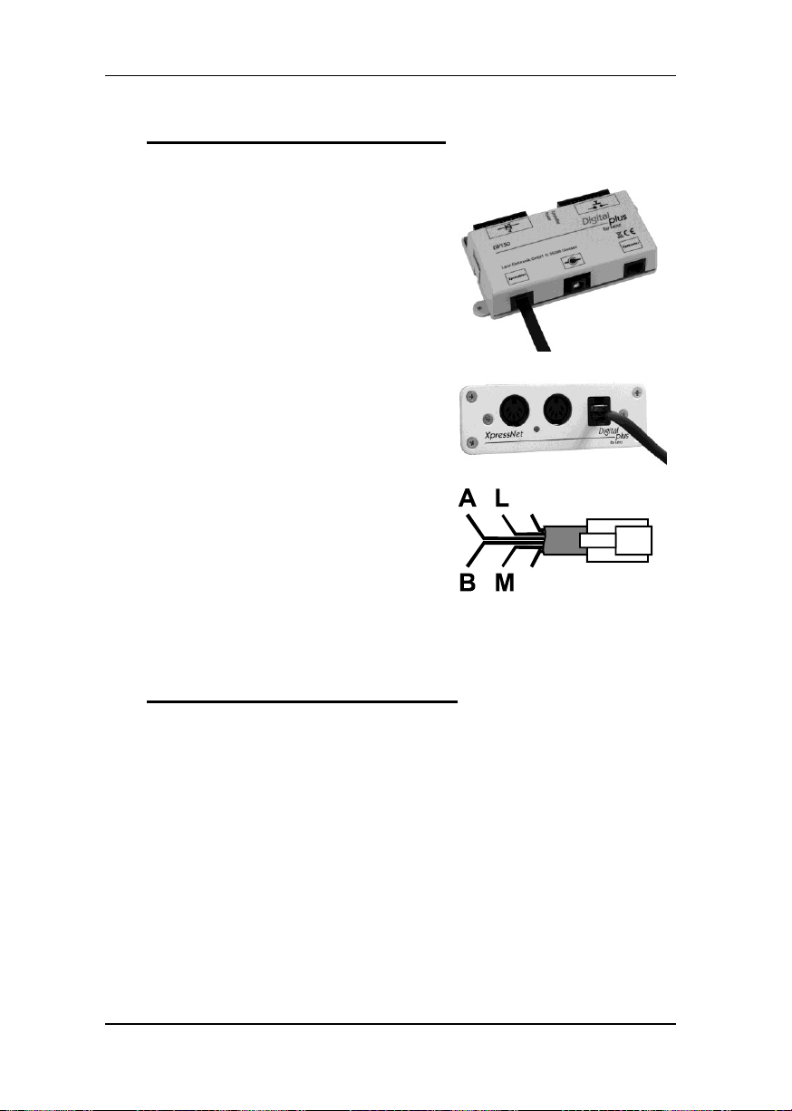
Use the cable included in the package to
connect the device to the XpressNet.
Plug one end into one of the two
"XpressNet" sockets of the LW150. Use
the second socket XpressNet" to
connect additional modules LW150.
Connect the other end of the connecting
cable to an adapter LA152.
To connect the LW150 to the terminal
screws LMAB of a LZ100 or LZV100
command station, simply cut the cable
at a suitable spot and connect the cable
wires to the corresponding terminal
screws of the LZ100 or LZV100. The pin
assignment is shown in the illustration
on the right.
do not use
do not use
7 Connection to the XpressNet
8 Connection to a power supply
The connection to a power supply is optional and required only under
certain circumstances when using a positions indicator. More
information can be found in the section "Optional power supply"
(p. 44).
Page 37
37
E
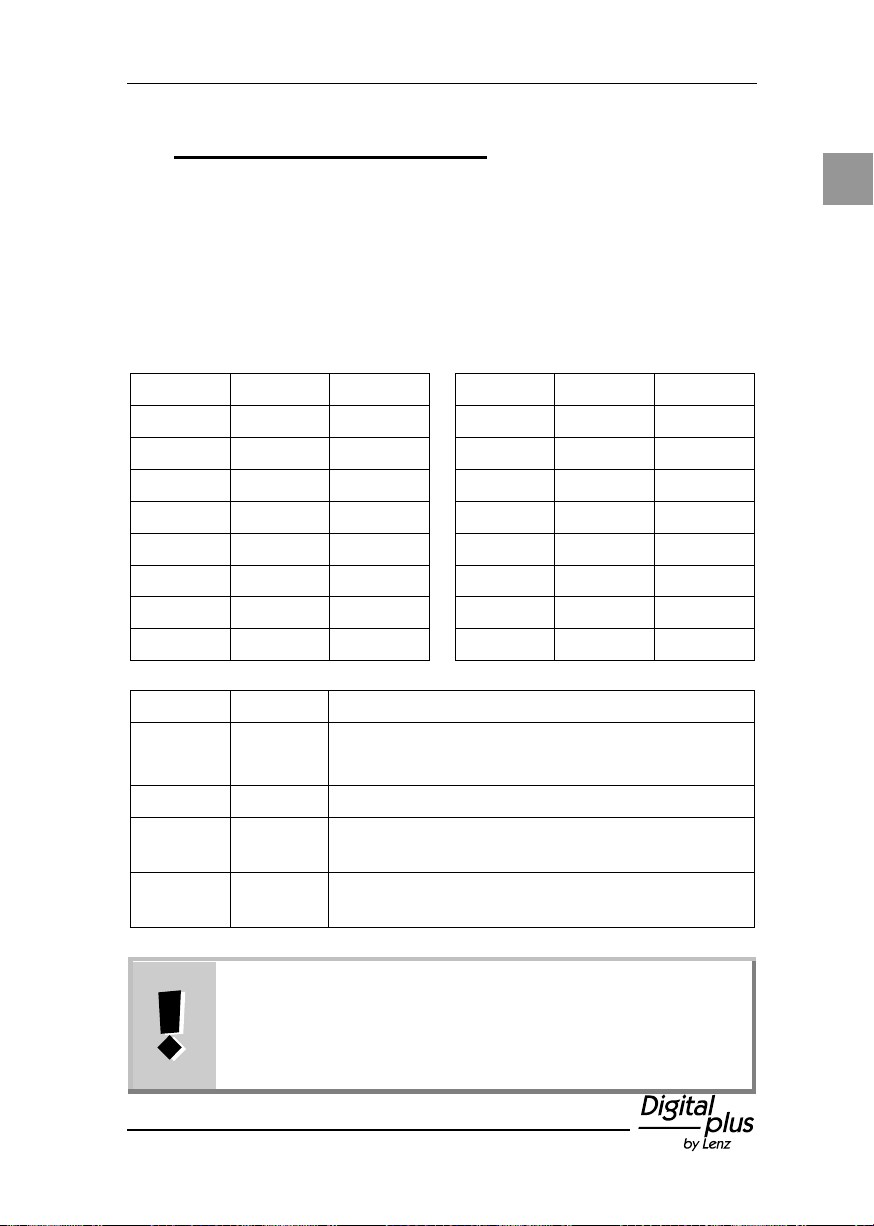
Wire no.
Colour
Point
Wire no.
Colour
Point
1
black
1 9
red 9 2
white
2 10
brown
10 3 grey
3 11
black
11
4
purple
4 12
white
12 5 blue
5 13
grey
13
6
green
6 14
purple
14
7
yellow
7 15
blue
15
8
orange
8 16
green
16
Wire no.
Colour
17
yellow
NOTAUS / EIN
(emergency shutdown / startup)
18
orange
Not used
19
red
Joint connection for position "-" or "AUS"
(OFF)
20
brown
Joint connection for position "+" or "EIN"
(ON)
Advice!
It is easiest to do the wiring by soldering the ends of the
connecting cable for the keys to a customary soldering
strip. From here, you can conveniently execute the wiring
to the keys / switches.
9 Connecting keys / switches
You can use keys (2 per point) or toggle switches (without centre
position) to switch points, signals, decouplers or other accessories.
You can use both keys and toggle switches together, but not
simultaneously (in parallel) for the same point.
Use the 20-wire cable enclosed in the package of the LW150 to
connect keys / toggle switches. To facilitate orientation, the individual
wires of the cable are colour-coded:
Page 38

38 Information LW150
Connect the keys / toggle switches for points 1 to 16 to wires 1 to 16.
A key for enabling the "NOTAUS" (emergency shutdown) function as
well as a key for disabling the "NOTAUS" function can be connected
to wire 17. Connecting these keys is optional. You must not use
switches for this function!
Page 39
39
E
""-
W1
""+
""-
W2
""+
""-
W16
""+
""-
ON
OFF
""+
(not assigned)
19 red
1 black
2 white
3 grey
4 purple
5 blue
6 green
7 yellow
8 orange
9 red
10 brown
11 black
12 white
13 grey
14 purple
15 blue
16 green
17 yellow
18 orange
20 brown
2 keys for point
1
2 keys for point
2
2 keys for point
16
…and so forth
up to
2 keys for
NOTAUS / EIN
(emergency
shutdown /
startup)
(optional)
The following illustration shows the connection of keys:
Page 40
40 Information LW150
""-
ON
OFF
""+
""-
W1
""+
""-
W2
""+
""-
W16
""+
(not assigned)
19 red
1 black
2 white
3 grey
4 purple
5 blue
6 green
7 yellow
8 orange
9 red
10 brown
11 black
12 white
13 grey
14 purple
15 blue
16 green
17 yellow
18 orange
20 brown
Toggle switch
for point 1
Toggle switch
for point 2
Toggle switch
for point 16
… and so forth
up to
2 keys
NOTAUS / EIN
(emergency
shutdown /
startup)
(optional)
The following illustration shows the connection of switches:
Page 41
41
E
You must not connect light bulbs to the LW150!
If you want to use different LEDs, use so-called “low-
current” types. A series resistor is not required; it is
already integrated into the device (1kOhm). The voltage at
the outputs for the LEDs is 5V.
When using toggle switches (instead of keys), the LED
flashes if the setting of the switch does not correspond to
the setting of the point indicated by the command station.
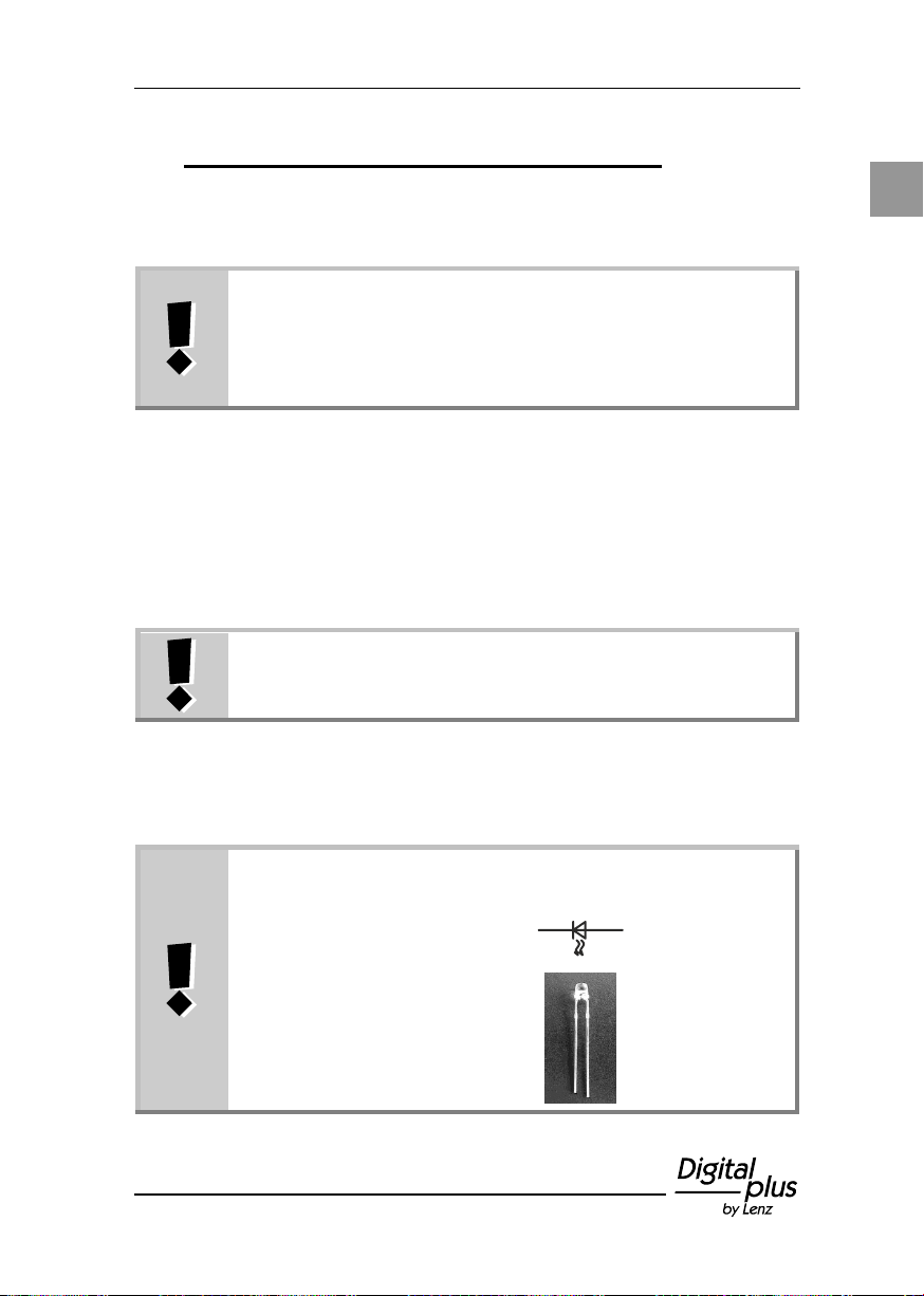
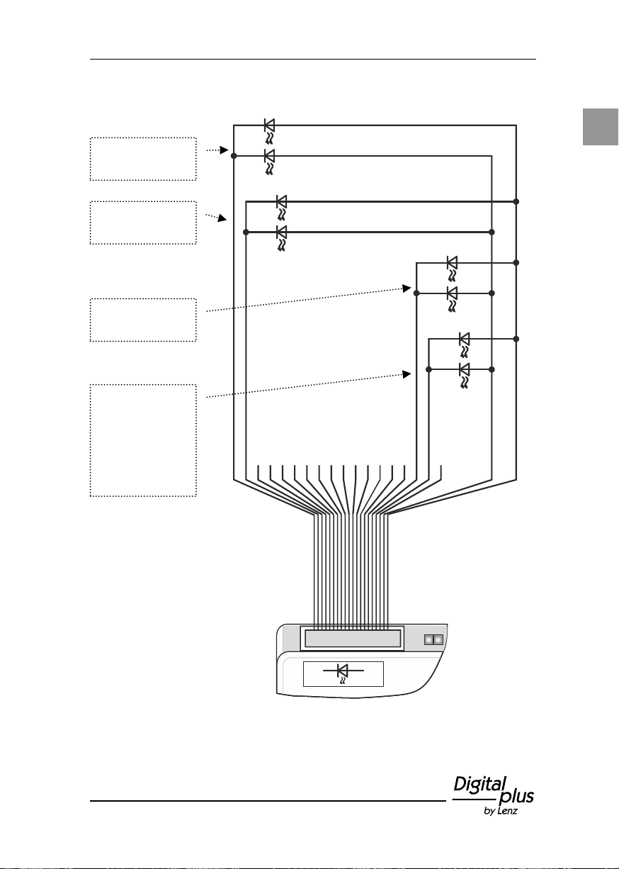
LEDs must be connected "the right way around". The two
connections of the LEDs are called "cathode" and "anode":
Symbol in wiring
plan
cathode
anode
Side view
short wire
long wire
10 Indicating the setting of points / signals
Use the complementary set (art. no. 80145) to indicate the setting of
points and signals. The set comprises a 20-wire connecting cable and
32 yellow LEDs.
When initialising the Digital plus system, the LW150 will react in
accordance with the setting of DIP switch 8 (see the section "Setting
the startup characteristics" p. 32). If the setting of a point is
changed during operation (e.g. by means of a manual control) the
indicator of the LW150 will change, too. When using feedbackenabled switch decoders LS100, a manual change of the setting of a
point is indicated, too (real feedback), provided the wiring of the
corresponding point drive has been effected correctly.
As was the case when connecting keys, we recommend soldering the
stripped wires of the connecting cable for the LEDs to a customary
soldering strip. To facilitate orientation, the wires have been colourcoded.
Page 42
42 Information LW150
Wire no.
Colour
Point
Wire no.
Colour
Point
1
black
1 9
red 9 2
white
2 10
brown
10 3 grey
3 11
black
11
4
purple
4 12
white
12 5 blue
5 13
grey
13
6
green
6 14
purple
14
7
yellow
7 15
blue
15
8
orange
8 16
green
16
Wire no.
Colour
17
yellow
The cathodes of two LEDs for indicating the
status AUS / EIN (ON / OFF) can be
connected to this wire.
18
orange
Not used
Wire no.
Colour
19
red
Joint connection of the anode of the LEDs
for position "-" or "AUS"
20
brown
Joint connection of the anode of the LEDs
for position "+" or "EIN"
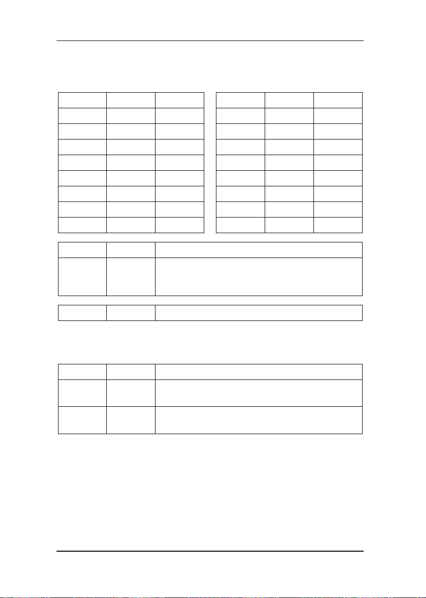
The following table shows the assignment of the wire to the cathode
connection of the LED to the corresponding point:
Use the following table for the anode connection (long wire) of the
LEDs:
Page 43
43
E
Anode LEDs setting “minus” / “OFF“
Anode LEDs setting “plus” / “ON“
W 1
""+
""-
W 2
""+
""-
W 16
""+
""-
ON
OFF
(not assigned)
19 red
1 black
2 white
3 grey
4 purple
5 blue
6 green
7 yellow
8 orange
9 red
10 brown
11 black
12 white
13 grey
14 purple
15 blue
16 green
17 yellow
18 orange
20 brown
Two LEDs for
point 1
Two LEDs for
point 2
Two LEDs for
point 16
…and so forth
up to
Two LEDs for
NOTAUS / EIN
(emergency
shutodown /
startup)
(optional)
The following illustration shows the connections of the LEDs:
Page 44
44 Information LW150
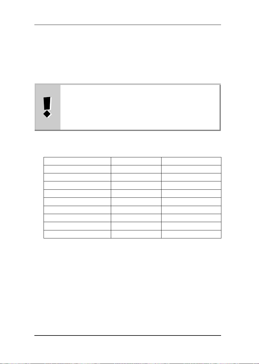
The power supply described here does not correspond to
the power supply of the track layout (connection J&K), but
only the devices connected to the XpressNet as well as
the connections CDE and RS.
The LZ/LZV100 can supply a maximum of 300mA for
these devices.
Device
Connection
Power consumption
Manual control LH100
XpressNet (LMAB)
28mA
Manual control LH90
XpressNet (LMAB)
18mA
Manual control LH01
XpressNet (LMAB)
30mA
Key module LW150
XpressNet (LMAB)
18mA (without LEDs)
Key module LW150
XpressNet (LMAB)
39mA (with LEDs)
Interface
XpressNet (LMAB)
21mA
Switch decoder LS100
RS
1.5mA
Feedback module LR101
RS
1.5mA
Amplifier LV101
CDE
10mA
10.1 Optional power supply
An optional power supply is only required if the power supplied by the
command station is not sufficient to supply all connected devices.
Among these devices are XpressNet devices (manual control,
Interface, key module) but also feedback-enabled decoders (feedback
modules and switch decoders) and amplifiers.
Use the following table to calculate the power consumption of devices
already in use:
If the supply of the command station is not sufficient, the green LED of
the key module will not shine. Use the mains adapter 26160 to supply
the LW150 with power.
Page 45
45
E
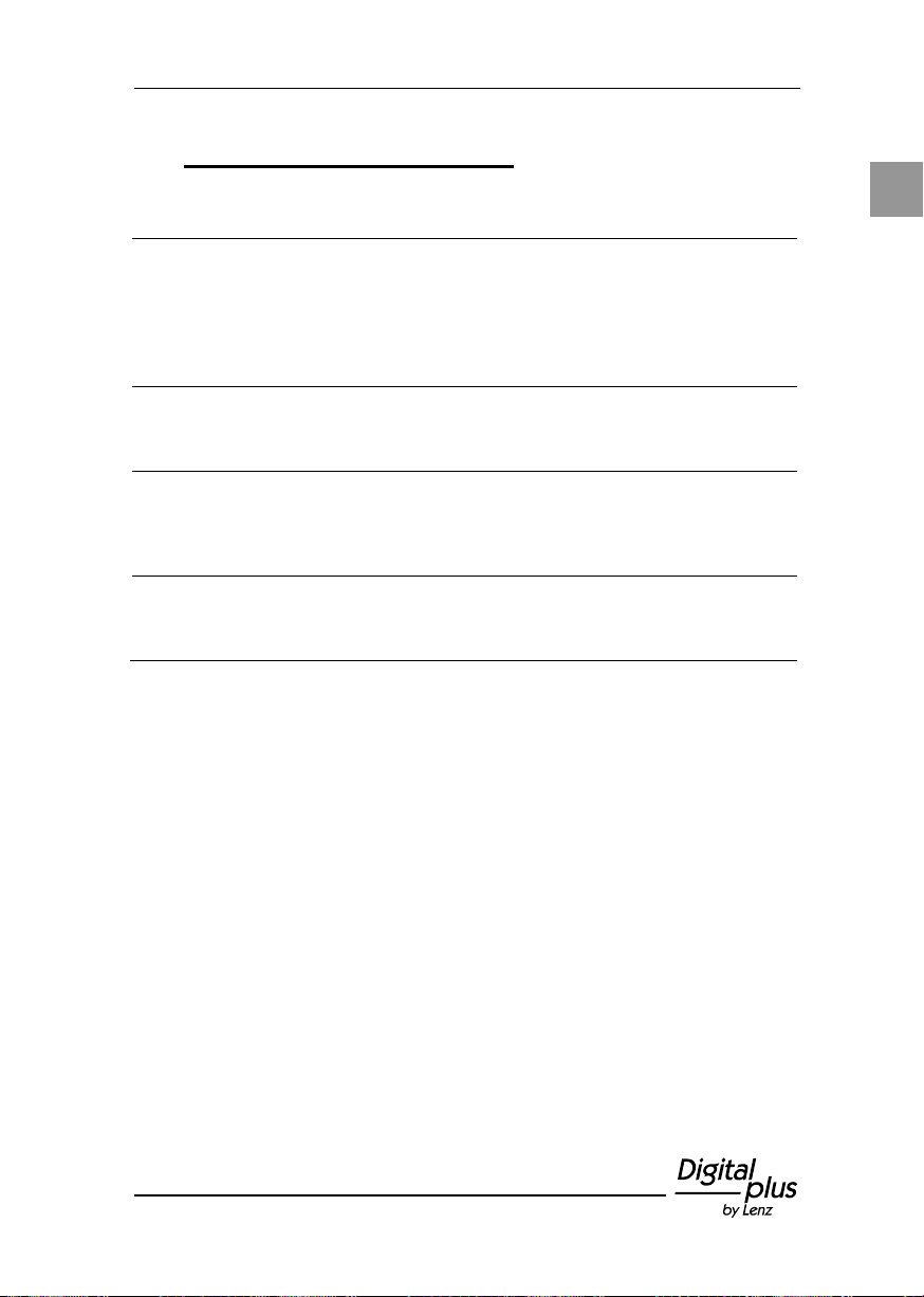
Malfunction
Cause
Correction
No function (green LED off)
No operating voltage or
XpressNet inactive
Check the wiring of the
XpressNet
Ensure that the power
supply of the XpressNet is
not overloaded (p. 44).
Points do not switch, but
indicator changes
Point address range set
incorrectly
Set the DIP switch for the
address range correctly
(p. 30).
Red LED flashes
Communication error
between command station
and LW150
Check the setting of the
XpressNet address
(p. 34) and restart the
system.
LEDs for indication of
setting do not shine
Poling or wiring error when
connecting the LEDs
Check the wiring and
polarity of the LEDs
(p. 41)
11 Help in case of malfunction
Page 46

46 Information LW150
Page 47

47
Page 48

48 Information LW150
Nicht geeignet für Kinder unter 14 Jahren wegen verschluckbarer Kleinteile. Bei
unsachgemäßem Gebrauch besteht Verletzungsgefahr durch funktionsbedingte Kanten
und Spitzen! Nur für trockene Räume. Irrtum sowie Änderung aufgrund des technischen
Fortschrittes, der Produktpflege oder anderer Herstellungsmethoden bleiben
bestimmungsgemäßen Gebrauch, Nichtbeachtung dieser Gebrauchsanweisung, Betrieb
not authorised for use with model railways, or transformers or other electrical equipment
violence or from overheating or from the effects of moisture etc. Furthermore, in all such
vorbehalten. Jede Haftung für Schäden und Folgeschäden durch nicht
mit nicht für Modellbahnen zugelassenen, umgebauten oder schadhaften
Transformatoren bzw. sonstigen elektrischen Geräten, eigenmächtigen Eingriff,
Gewalteinwirkung, Überhitzung, Feuchtigkeitseinwirkung u.ä. ist ausgeschlossen;
außerdem erlischt der Gewährleistungsanspruch.
Diese Betriebsanleitung bitte für späteren Gebrauch aufbewahren!
Not suitable for children under fourteen because of the danger of their swallowing the
small constituent pieces. Improper use can result in injury by functionally necessary
points and edges. For use only in dry areas. We reserve the right to make changes in
line with technical progress, product maintenance or changes in production methods.
We accept no responsibility for errors which may occur for similar reasons. We accept
no responsibility for direct or indirect damage resulting from improper use, non-
observance of instructions, use of transformers or other electrical equipment which is
which has been altered or adapted or which is faulty. Nor can we accept responsibility
when damage results from unsupervised adjustments to equipment or from acts of
cases guarantees become invalid.
Keep this operation manual for future reference!
Vogelsang 14
35398 Giessen
Hotline: 06403 900 133
Fax: 06403 900 155
www.lenz-elektronik.de
 Loading...