

Lenovo Y720 Cube Quick Start Guide [en, ar, bg, cs, da, de, el, es, et, fi, fr, he, hr, hu, it, ja, ko, nb, nl, pl, pt, ro, ru, sk, sl, sr, sv, th, tr, uk, zh]
Page 1

ideacentreY720CubeHardwareMaintenance
Manual
MachineTypes:90H2[Y720Cube-15ISH/EnergyStar]/90H3[Y720
Cube-15ISH/NoneEnergyStar]
Page 2

Page 3

ideacentreY720Cube
HardwareMaintenanceManual
MachineTypes:90H2[Y720Cube-15ISH/EnergyStar]/90H3[Y720
Cube-15ISH/NoneEnergyStar]
Page 4

FirstEdition(July2016)4th
©CopyrightLenovo2016.
LIMITEDANDRESTRICTEDRIGHTSNOTICE:IfdataorsoftwarearedeliveredpursuantaGeneralServices
Administration“GSA”contract,use,reproduction,ordisclosureissubjecttorestrictionssetforthinContractNo.
GS-35F-05925
Page 5

Contents
Chapter1.Aboutthismanual.....1
ImportantSafetyInformation.........1
Chapter2.Safetyinformation.....3
Generalsafety...............3
Electricalsafety..............3
Safetyinspectionguide...........5
Handlingelectrostaticdischarge-sensitive
devices.................5
Groundingrequirements...........6
Safetynotices...............6
Chapter3.Generalinformation....9
Specifications...............9
Chapter4.GeneralCheckout.....11
Chapter5.UsingtheSetupUtility...13
StartingtheLenovoBIOSSetupUtilityprogram.13
Viewingandchangingsettings........13
Usingpasswords..............13
Enablingordisablingadevice........15
Selectingastartupdevice..........16
ExitingtheLenovoBIOSSetupUtilityprogram..17
Chapter6.Symptom-to-FRUIndex..19
Harddiskdrivebooterror..........19
PowerSupplyProblems...........19
AdditionalServiceInformation........19
POSTerrorcodes.............20
Undeterminedproblems...........20
Chapter7.Locations.........23
Identifyinginternalcomponents........23
Identifyingpartsonthesystemboard......25
Chapter8.Replacinghardware....27
Generalinformation.............27
Replacingthekeyboardandmouse......28
Removingthecomputercover........28
Removingthecomputercover(Lenovologo)...29
Removingthetopcover...........30
Removingthebottomcover.........32
Removingthefrontbezel..........33
Replacingthexboxdongle..........34
Replacingamemorymodule.........36
Replacingaharddiskdrive..........37
Replacingasolidstatedrive.........38
Replacingtheheat-sinkassembly.......41
ReplacingtheWi-Ficard...........43
Replacingagraphicscard..........44
ReplacingtheCPU.............47
ReplacingthePowersupply.........49
Replacingthemotherboard..........52
ReplacingthefrontI/Omodule........53
FRUlists.................54
Chapter9.Generalinformation....61
AdditionalServiceInformation........61
©CopyrightLenovo2016
iii
Page 6

ivideacentreY720CubeHardwareMaintenanceManual
Page 7
Chapter1.Aboutthismanual
ThismanualcontainsserviceandreferenceinformationforideacntreY720Cubedesktopcomputerslisted
onthecover.ItisintendedonlyfortrainedservicerswhoarefamiliarwithLenovocomputerproducts.
BeforeservicingaLenovoproduct,besuretoreadtheSafetyInformation.
ThedescriptionoftheTVcardinthismanualisonlyusedforthemachineswhichhavetheTVcard.Itis
invalidforthosemachineswhichdonothaveTVcard.
ImportantSafetyInformation
Important:SystemrequirementwarningtermsforY720Cube
YourthermalequipmentMUSTbeconsistentwithyourownclockfrequencyand/orvoltagesettings.
Besuretoreadallcautionanddangerstatementsinthisbookbeforeperforminganyoftheinstructions.
VeuillezliretouteslesconsignesdetypeDANGERetA TTENTIONduprésentdocumentavantd’exécuter
lesinstructions.
LesenSieunbedingtalleHinweisevomT yp“ACHTUNG”oder“VORSICHT”indieserDokumentation,bevor
SieirgendwelcheVorgängedurchführen
LeggereleistruzioniintrodottedaA TTENZIONEePERICOLOpresentinelmanualeprimadieseguireuna
qualsiasidelleistruzioni
Certifique-sedelertodasasinstruçõesdecuidadoeperigonestemanualantesdeexecutarqualquer
umadasinstruções
Esimportantequeleatodaslasdeclaracionesdeprecauciónydepeligrodeestemanualantesdeseguir
lasinstrucciones.
©CopyrightLenovo2016
1
Page 8

2ideacentreY720CubeHardwareMaintenanceManual
Page 9

Chapter2.Safetyinformation
Thischaptercontainsthesafetyinformationthatyouneedtobefamiliarwithbeforeservicingacomputer.
Generalsafety
Followtheserulestoensuregeneralsafety:
•Observegoodhousekeepingintheareaofthemachinesduringandaftermaintenance.
•Whenliftinganyheavyobject:
1.Ensureyoucanstandsafelywithoutslipping.
2.Distributetheweightoftheobjectequallybetweenyourfeet.
3.Useaslowliftingforce.Nevermovesuddenlyortwistwhenyouattempttolift.
4.Liftbystandingorbypushingupwithyourlegmuscles;thisactionremovesthestrainfromthe
musclesinyourback.
Donotattempttoliftanyobjectsthatweighmorethan16kg(35lb)orobjectsthatyouthinkare
tooheavyforyou.
•Donotperformanyactionthatcauseshazardstothecustomer,orthatmakestheequipmentunsafe.
•Beforeyoustartthemachine,ensurethatotherservicerepresentativesandthecustomer’spersonnelare
notinahazardousposition.
•Placeremovedcoversandotherpartsinasafeplace,awayfromallpersonnel,whileyouareservicing
themachine.
•Keepyourtoolcaseawayfromwalkareassothatotherpeoplewillnottripoverit.
•Donotwearlooseclothingthatcanbetrappedinthemovingpartsofamachine.Ensurethatyoursleeves
arefastenedorrolledupaboveyourelbows.Ifyourhairislong,fastenit.
•Inserttheendsofyournecktieorscarfinsideclothingorfastenitwithanonconductiveclip,approximately
8centimeters(3inches)fromtheend.
•Donotwearjewelry,chains,metal-frameeyeglasses,ormetalfastenersforyourclothing.
Remember:Metalobjectsaregoodelectricalconductors.
•Wearsafetyglasseswhenyouare:hammering,drillingsoldering,cuttingwire,attachingsprings,using
solvents,orworkinginanyotherconditionsthatmightbehazardoustoyoureyes.
•Afterservice,reinstallallsafetyshields,guards,labels,andgroundwires.Replaceanysafetydevice
thatiswornordefective.
•Reinstallallcoverscorrectlybeforereturningthemachinetothecustomer.
Electricalsafety
CAUTION:
Electricalcurrentfrompower,telephone,andcommunicationcablescanbehazardous.Toavoid
personalinjuryorequipmentdamage,disconnecttheattachedpowercords,telecommunication
systems,networks,andmodemsbeforeyouopenthecomputercovers,unlessinstructedotherwise
intheinstallationandconfigurationprocedures.
©CopyrightLenovo2016
3
Page 10

Observethefollowingruleswhenworkingonelectricalequipment.
Important:Useonlyapprovedtoolsandtestequipment.Somehandtoolshavehandlescoveredwithasoft
materialthatdoesnotinsulateyouwhenworkingwithliveelectricalcurrents.Manycustomershave,near
theirequipment,rubberfloormatsthatcontainsmallconductivefiberstodecreaseelectrostaticdischarges.
Donotusethistypeofmattoprotectyourselffromelectricalshock.
•Findtheroomemergencypower-off(EPO)switch,disconnectingswitch,orelectricaloutlet.Ifanelectrical
accidentoccurs,youcanthenoperatetheswitchorunplugthepowercordquickly.
•Donotworkaloneunderhazardousconditionsornearequipmentthathashazardousvoltages.
•Disconnectallpowerbefore:
–Performingamechanicalinspection
–Workingnearpowersupplies
–RemovingorinstallingFieldReplaceableUnits(FRUs)
•Beforeyoustarttoworkonthemachine,unplugthepowercord.Ifyoucannotunplugit,askthecustomer
topower-offthewallboxthatsuppliespowertothemachineandtolockthewallboxintheoffposition.
•Ifyouneedtoworkonamachinethathasexposedelectricalcircuits,observethefollowingprecautions:
–Ensurethatanotherperson,familiarwiththepower-offcontrols,isnearyou.
Remember:Anotherpersonmustbetheretoswitchoffthepower,ifnecessary.
–Useonlyonehandwhenworkingwithpowered-onelectricalequipment;keeptheotherhandinyour
pocketorbehindyourback.
Remember:Theremustbeacompletecircuittocauseelectricalshock.Byobservingtheaboverule,
youmaypreventacurrentfrompassingthroughyourbody.
–Whenusingatester,setthecontrolscorrectlyandusetheapprovedprobeleadsandaccessoriesfor
thattester.
–Standonsuitablerubbermats(obtainedlocally,ifnecessary)toinsulateyoufromgroundssuchas
metalfloorstripsandmachineframes.
Observethespecialsafetyprecautionswhenyouworkwithveryhighvoltages;theseinstructionsarein
thesafetysectionsofmaintenanceinformation.Useextremecarewhenmeasuringhighvoltages.
•Regularlyinspectandmaintainyourelectricalhandtoolsforsafeoperationalcondition.
•Donotusewornorbrokentoolsandtesters.
•Neverassumethatpowerhasbeendisconnectedfromacircuit.First,checkthatithasbeenpowered-off.
•Alwayslookcarefullyforpossiblehazardsinyourworkarea.Examplesofthesehazardsaremoistfloors,
nongroundedpowerextensioncables,powersurges,andmissingsafetygrounds.
•Donottouchliveelectricalcircuitswiththereflectivesurfaceofaplasticdentalmirror.Thesurfaceis
conductive;suchtouchingcancausepersonalinjuryandmachinedamage.
•Donotservicethefollowingpartswiththepoweronwhentheyareremovedfromtheirnormaloperating
placesinamachine:
–Powersupplyunits
–Pumps
–Blowersandfans
–Motorgenerators
andsimilarunits.(Thispracticeensurescorrectgroundingoftheunits.)
•Ifanelectricalaccidentoccurs:
–Usecaution;donotbecomeavictimyourself.
–Switchoffpower.
4ideacentreY720CubeHardwareMaintenanceManual
Page 11

–Sendanotherpersontogetmedicalaid.
Safetyinspectionguide
Theintentofthisinspectionguideistoassistyouinidentifyingpotentiallyunsafeconditionsonthese
products.Eachmachine,asitwasdesignedandbuilt,hadrequiredsafetyitemsinstalledtoprotectusers
andservicepersonnelfrominjury.Thisguideaddressesonlythoseitems.However,goodjudgmentshould
beusedtoidentifypotentialsafetyhazardsduetoattachmentoffeaturesoroptionsnotcoveredbythis
inspectionguide.
Ifanyunsafeconditionsarepresent,youmustdeterminehowserioustheapparenthazardcouldbeand
whetheryoucancontinuewithoutfirstcorrectingtheproblem.
Considertheseconditionsandthesafetyhazardstheypresent:
•Electricalhazards,especiallyprimarypower(primaryvoltageontheframecancauseseriousorfatal
electricalshock).
•Explosivehazards,suchasadamagedCRTfaceorbulgingcapacitor
•Mechanicalhazards,suchaslooseormissinghardware
Theguideconsistsofaseriesofstepspresentedinachecklist.Beginthecheckswiththepoweroff,and
thepowercorddisconnected.
Checklist:
1.Checkexteriorcoversfordamage(loose,broken,orsharpedges).
2.Power-offthecomputer.Disconnectthepowercord.
3.Checkthepowercordfor:
a.Athird-wiregroundconnectoringoodcondition.Useametertomeasurethird-wireground
continuityfor0.1ohmorlessbetweentheexternalgroundpinandframeground.
b.Thepowercordshouldbetheappropriatetypeasspecifiedinthepartslistings.
c.Insulationmustnotbefrayedorworn.
4.Removethecover.
5.Checkforanyobviousalterations.Usegoodjudgmentastothesafetyofanyalterations.
6.Checkinsidetheunitforanyobviousunsafeconditions,suchasmetalfilings,contamination,wateror
otherliquids,orsignsoffireorsmokedamage.
7.Checkforworn,frayed,orpinchedcables.
8.Checkthatthepower-supplycoverfasteners(screwsorrivets)havenotbeenremovedortamperedwith.
Handlingelectrostaticdischarge-sensitivedevices
Anycomputerpartcontainingtransistorsorintegratedcircuits(ICs)shouldbeconsideredsensitiveto
electrostaticdischarge(ESD).ESDdamagecanoccurwhenthereisadifferenceinchargebetweenobjects.
ProtectagainstESDdamagebyequalizingthechargesothatthemachine,thepart,theworkmat,andthe
personhandlingthepartareallatthesamecharge.
Notes:
1.Useproduct-specificESDprocedureswhentheyexceedtherequirementsnotedhere.
2.MakesurethattheESDprotectivedevicesyouusehavebeencertified(ISO9000)asfullyeffective.
WhenhandlingESD-sensitiveparts:
•Keepthepartsinprotectivepackagesuntiltheyareinsertedintotheproduct.
Chapter2.Safetyinformation5
Page 12
•Avoidcontactwithotherpeoplewhilehandlingthepart.
•Wearagroundedwriststrapagainstyourskintoeliminatestaticonyourbody.
•Preventthepartfromtouchingyourclothing.Mostclothingisinsulativeandretainsachargeeven
whenyouarewearingawriststrap.
•Usetheblacksideofagroundedworkmattoprovideastatic-freeworksurface.Thematisespecially
usefulwhenhandlingESD-sensitivedevices.
•Selectagroundingsystem,suchasthoselistedbelow,toprovideprotectionthatmeetsthespecific
servicerequirement.
Note:TheuseofagroundingsystemisdesirablebutnotrequiredtoprotectagainstESDdamage.
–AttachtheESDgroundcliptoanyframeground,groundbraid,orgreen-wireground.
–UseanESDcommongroundorreferencepointwhenworkingonadouble-insulatedor
battery-operatedsystem.Y oucanusecoaxorconnector-outsideshellsonthesesystems.
–Usetheroundground-prongoftheacplugonac-operatedcomputers.
Groundingrequirements
Electricalgroundingofthecomputerisrequiredforoperatorsafetyandcorrectsystemfunction.Proper
groundingoftheelectricaloutletcanbeverifiedbyacertifiedelectrician.
Safetynotices
ThecautionanddangersafetynoticesinthissectionareprovidedinthethelanguageofEnglish.
DANGER
Electricalcurrentfrompower,telephoneandcommunicationcablesishazardous.
Toavoidashockhazard:
•Donotconnectordisconnectanycablesorperforminstallation,maintenance,orreconfiguration
ofthisproductduringanelectricalstorm.
•Connectallpowercordstoaproperlywiredandgroundedelectricaloutlet.
•Connecttoproperlywiredoutletsanyequipmentthatwillbeattachedtothisproduct.
•Whenpossible,useonehandonlytoconnectordisconnectsignalcables.
•Neverturnonanyequipmentwhenthereisevidenceoffire,water,orstructuraldamage.
•Disconnecttheattachedpowercords,telecommunicationssystems,networks,andmodems
beforeyouopenthedevicecovers,unlessinstructedotherwiseintheinstallationandconfiguration
procedures.
•Connectanddisconnectcablesasdescribedinthefollowingtablewheninstalling,moving,or
openingcoversonthisproductorattacheddevices.
6ideacentreY720CubeHardwareMaintenanceManual
Page 13
ToConnect
1.T urneverythingOFF .
2.First,attachallcablestodevices.
3.Attachsignalcablestoconnectors.
4.Attachpowercordstooutlet.
5.T urndeviceON.
ToDisconnect
1.T urneverythingOFF .
2.First,removepowercordsfromoutlet.
3.Removesignalcablesfromconnectors.
4.Removeallcablesfromdevices.
CAUTION:
Whenreplacingthelithiumbattery,useonlyPartNumber45C1566oranequivalenttypebattery
recommendedbythemanufacturer.Ifyoursystemhasamodulecontainingalithiumbattery,replace
itonlywiththesamemoduletypemadebythesamemanufacturer.Thebatterycontainslithiumand
canexplodeifnotproperlyused,handled,ordisposedof.
Donot:
•Throworimmerseintowater
•Heattomorethan100°C(212°F)
•Repairordisassemble
Disposeofthebatteryasrequiredbylocalordinancesorregulations.
CAUTION:
Whenlaserproducts(suchasCD-ROMs,DVD-ROMdrives,fiberopticdevices,ortransmitters)are
installed,notethefollowing:
•Donotremovethecovers.Removingthecoversofthelaserproductcouldresultinexposureto
hazardouslaserradiation.Therearenoserviceablepartsinsidethedevice.
•Useofcontrolsoradjustmentsorperformanceofproceduresotherthanthosespecifiedherein
mightresultinhazardousradiationexposure.
DANGER
SomelaserproductscontainanembeddedClass3AorClass3Blaserdiode.Notethefollowing:
Laserradiationwhenopen.Donotstareintothebeam,donotviewdirectlywithoptical
instruments,andavoiddirectexposuretothebeam.
Chapter2.Safetyinformation7
Page 14
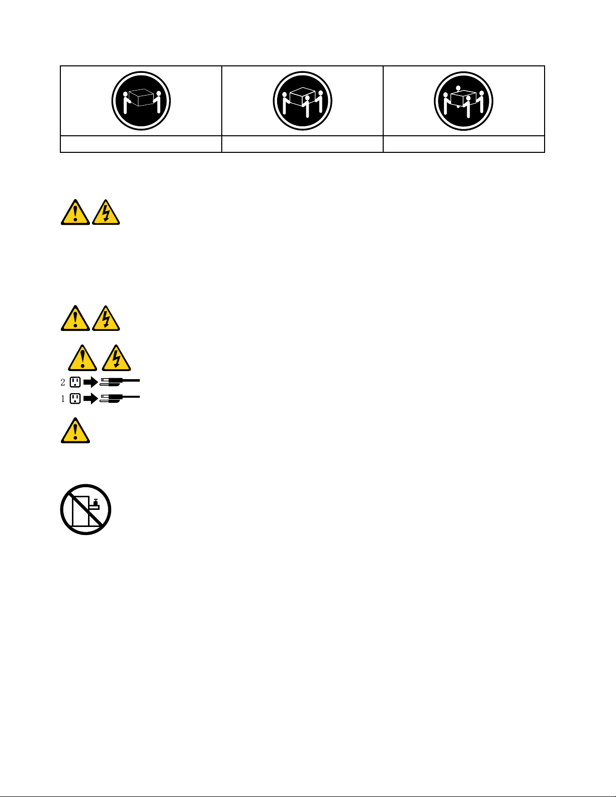
≥18kg(37lbs)≥32kg(70.5lbs)≥55kg(121.2lbs)
CAUTION:
Usesafepracticeswhenlifting.
CAUTION:
Thepowercontrolbuttononthedeviceandthepowerswitchonthepowersupplydonotturnoff
theelectricalcurrentsuppliedtothedevice.Thedevicealsomighthavemorethanonepower
cord.Toremoveallelectricalcurrentfromthedevice,ensurethatallpowercordsaredisconnected
fromthepowersource.
CAUTION:
Donotplaceanyobjectweighingmorethan82kg(180lbs.)ontopofrack-mounteddevices.
8ideacentreY720CubeHardwareMaintenanceManual
Page 15

Chapter3.Generalinformation
Thischapterprovidesgeneralinformationthatappliestoallmachinetypessupportedbythispublication.
Specifications
Thissectionliststhephysicalspecificationsforyourcomputer.
Thissectionliststhephysicalspecificationsforyourcomputer.
TypeideacentreY720Cube
Thissectionliststhephysicalspecifications.
Environment
Airtemperature:
Operating:10°to35°C
Transit:-20°to55°C
Humidity:
Operating:35%to80%
Transit:20%to90%(40°C)
Altitude:86KPato106KPa
Electricalinput:
Inputvoltage:90V-264V(AC)
Inputfrequency:47Hz-63Hz
©CopyrightLenovo2016
9
Page 16

10ideacentreY720CubeHardwareMaintenanceManual
Page 17

Chapter4.GeneralCheckout
Attention:Thedrivesinthecomputeryouareservicingmighthavebeenrearrangedorthedrivestartup
sequencechanged.Beextremelycarefulduringwriteoperationssuchascopying,saving,orformatting.
Dataorprogramscanbeoverwrittenifyouselectanincorrectdrive.
Generalerrormessagesappearifaproblemorconflictisfoundbyanapplicationprogram,theoperating
system,orboth.Foranexplanationofthesemessages,refertotheinformationsuppliedwiththatsoftware
package.
Usethefollowingproceduretohelpdeterminethecauseoftheproblem:
1.Power-offthecomputerandallexternaldevices.
2.Checkallcablesandpowercords.
3.Setalldisplaycontrolstothemiddleposition.
4.Power-onallexternaldevices.
5.Power-onthecomputer.
•Lookfordisplayederrorcodes
•Lookforreadableinstructionsoramainmenuonthedisplay.
Ifyoudidnotreceivethecorrectresponse,proceedtostep6.
Ifyoudoreceivethecorrectresponse,proceedtostep7.
6.Lookatthefollowingconditionsandfollowtheinstructions:
•IfthecomputerdisplaysaPOSTerror,goto“POSTerrorcodes” .
•Ifthecomputerhangsandnoerrorisdisplayed,continueatstep7.
7.Iftheteststopsandyoucannotcontinue,replacethelastdevicetested.
©CopyrightLenovo2016
11
Page 18

12ideacentreY720CubeHardwareMaintenanceManual
Page 19

Chapter5.UsingtheSetupUtility
TheSetupUtilityprogramisusedtoviewandchangetheconfigurationsettingsofyourcomputer,regardless
ofwhichoperatingsystemyouareusing.However,theoperating-systemsettingsmightoverrideanysimilar
settingsintheSetupUtilityprogram.
StartingtheLenovoBIOSSetupUtilityprogram
TostarttheLenovoBIOSSetupUtilityprogram,dothefollowing:
1.Ifyourcomputerisalreadyonwhenyoustartthisprocedure,shutdowntheoperatingsystemand
turnoffthecomputer.
2.PressandholdtheF1keythenturnonthecomputer.WhentheLenovoBIOSSetupUtilityprogramis
displayed,releasetheF1key.
Note:IfaPower-OnPasswordoranAdministratorPasswordhasbeenset,theSetupUtilityprogrammenu
isnotdisplayeduntilyoutypeyourpassword.Formoreinformation,see“Usingpasswords.”
Viewingandchangingsettings
SystemconfigurationoptionsarelistedintheLenovoBIOSSetupUtilityprogrammenu.Tovieworchange
settings,see“StartingtheSetupUtilityprogram. ”
YoumustusethekeyboardwhenusingtheLenovoBIOSSetupUtilitymenu.Thekeysusedtoperform
varioustasksaredisplayedonthebottomofeachscreen.
Usingpasswords
YoucanusetheLenovoBIOSSetupUtilityprogramtosetpasswordstopreventunauthorizedpersons
fromgainingaccesstoyourcomputeranddata.See“StartingtheSetupUtilityprogram.”Thefollowing
typesofpasswordsareavailable:
•SetAdministratorPassword
•SetPower-OnPassword
Youdonothavetosetanypasswordstouseyourcomputer.However,ifyoudecidetosetpasswords,read
thefollowingsections.
Passwordconsiderations
Apasswordcanbeanycombinationoflettersandnumbersupto16character(a-z,and0-9).Forsecurity
reasons,itisagoodideatouseastrongpasswordthatcannotbeeasilycompromised.Wesuggestthat
passwordsshouldfollowtheserules:
•Strongpasswordscontain7-16characters,combinelettersandnumbers.
•Donotuseyournameoryourusername.
•Donotuseacommonwordoracommonname.
•Besignificantlydifferentfromyourpreviouspassword.
Attention:AdministratorandPower-Onpasswordsarenotcasesensitive
©CopyrightLenovo2016
13
Page 20

AdministratorPassword
SettinganAdministratorPassworddetersunauthorizedpersonsfromchangingconfigurationsettings.You
mightwanttosetanAdministratorPasswordifyouareresponsibleformaintainingthesettingsofseveral
computers.
AfteryousetanAdministratorPassword,apasswordpromptisdisplayedeverytimeyouaccesstheLenovo
BIOSSetupUtilityprogram.
IfboththeAdministratorandPower-OnPasswordareset,youcantypeeitherpassword.However,youmust
useyourAdministratorPasswordtochangeanyconfigurationsettings.
Setting,changing,ordeletinganAdministratorpassword
TosetanAdministratorPassword,dothefollowing:
Note:Apasswordcanbeanycombinationoflettersandnumbersupto16character(a-z,and0-9).For
moreinformation,see“Passwordconsiderations”onpage13.
1.StarttheLenovoBIOSSetupUtilityprogram(see“StartingtheLenovoBIOSSetupUtilityprogram”on
page13).
2.FromtheSecuritymenu,selectSetAdministratorPasswordandpresstheEnterkey.
3.Thepassworddialogboxwillbedisplayed.TypethepasswordthenpresstheEnterkey.
4.Re-typethepasswordtoconfirm,thenpresstheEnterkey.Ifyoutypethepasswordcorrectly,the
passwordwillbeinstalled.
TochangeanAdministratorPassword,dothefollowing:
1.StarttheLenovoBIOSSetupUtilityprogram(see“StartingtheLenovoBIOSSetupUtilityprogram”on
page13).
2.FromtheSecuritymenu,selectSetAdministratorPasswordandpresstheEnterkey.
3.Thepassworddialogboxwillbedisplayed.T ypethecurrentpasswordthenpressEnterkey.
4.T ypethenewpassword,thenpressEnterkey.Re-typethepasswordtoconfirmthenewpassword,if
youtypethenewpasswordcorrectly,thenewpasswordwillbeinstalled.ASetupNoticewilldisplay
thatchangeshavebeensaved.
TodeleteapreviouslysetAdministratorPassword,dothefollowing:
1.FromtheSecuritymenu,selectSetAdministratorPasswordandpresstheEnterkey.
2.Thepassworddialogboxwillbedisplayed.TypethecurrentpasswordandpresstheEnterkey.
3.T odeleteanAdministratorPassword,Enterblankfieldsforeachnewpasswordlineitem.Asetup
noticewilldisplaythatchangeshavebeensaved.
4.ReturntotheLenovoBIOSSetupUtilityprogrammenuandselecttheExitoption.
5.SelectSavechangesandExitfromthemenu.
Power-OnPassword
WhenaPower-OnPasswordisset,youcannotstarttheLenovoBIOSSetupUtilityprogramuntilavalid
passwordistypedfromthekeyboard.
Setting,changing,ordeletingaPower-OnPassword
Note:Apasswordcanbeanycombinationoflettersandnumbersupto16character(a-z,and0-9).
14ideacentreY720CubeHardwareMaintenanceManual
Page 21

TosetaPower-OnPassword,dothefollowing:
1.StarttheLenovoBIOSSetupUtilityprogram(See”StartingtheLenovoBIOSSetupUtilityprogram”on
page13.)
2.FromtheSecuritymenu,selectSetPower-OnPasswordandpresstheEnterkey.
3.Thepassworddialogboxwillbedisplayed.Typethepassword,andpresstheEnterkey.
4.Re-typethepasswordtoconfirm,ifyoutypethepasswordcorrectly,thepasswordwillbeinstalled.
TochangeaPower-OnPassword,dothefollowing:
1.StarttheLenovoBIOSSetupUtilityprogram(See”StartingtheLenovoBIOSSetupUtilityprogram”on
page13.)
2.FromtheSecuritymenu,selectSetPower-OnPasswordandpresstheEnterkey.
3.Thepassworddialogboxwillbedisplayed.TypethecurrentpasswordthenpresstheEnterkey.
4.T ypethenewpassword,thenpresstheEnterkey.Re-typethepasswordtoconfirmthenewpassword,
ifyoutypethenewpasswordcorrectly,thenewpasswordwillbeinstalled.Asetupnoticewilldisplay
thatchangeshavebeensaved.
TodeleteapreviouslysetPower-OnPassword,dothefollowing:
1.FromtheSecuritymenu,selectSetPower-OnPasswordandpresstheEnterkey.
2.Thepassworddialogboxwillbedisplayed.TypethecurrentpasswordandpresstheEnterkey.
3.T odeletethePower-OnPassword,Enterblankfieldsforeachnewpasswordlineitem.Asetup
noticewilldisplaythatchangeshavebeensaved.
4.ReturntotheLenovoBIOSSetupUtilityprogrammenuandselecttheExitoption.
5.SelectSavechangesandExitfromthemenu.
Enablingordisablingadevice
TheDevicesoptionsisusedtoenableordisableuseraccesstothefollowingdevices:
USBFunctionsSelectwhethertoenableordisableUSB(UniversalSerial
Bus)functions.Ifthefunctionsaredisabled,noUSB
devicescanbeused.
ATADriveSetupSelectIDEorACHImode.Devicedriversupportis
requiredforACHImode.Dependingonhowtheharddisk
imagewasinstalled,changingthissettingmayprevent
thesystemfrombooting.
OnboardAudioControllerSelectwhethertoenableordisabletheOnboardAudio
Controller,whenfeatureissettoDisabledalldevices
connectedtotheaudioconnectors(e.g.aheadphoneor
amicrophone)aredisabledandcan’tbeused.
OnboardEthernetControllerorBootAgentSelectwhethertoenableordisableOnboardEthernet
Controller,orselectwhethertoenableordisableload
onboardPXE(PrebootExecutionEnvironment),or
SMC(SecureManagedClient).Thisfeaturewillallow
thecomputertobootfromaserverimage.
Toenableordisableadevice,dothefollowing:
1.StarttheSetupUtilityprogram(see“StartingtheSetupUtilityprogram”onpage13).
2.FromtheSetupUtilityprogrammenu,selectDevices.
3.Select:
Chapter5.UsingtheSetupUtility15
Page 22

USBSetuppresstheEnterkey,andthenselectUSBFunctions.
ATADeviceSetuppresstheEnterkey.SelectConfigureSA T Aas,presstheEnterkeyandthen
selectSATAmode.
AudioSetuppresstheEnterkey,andthenselectOnboardAudioController.
NetworkSetuppresstheEnterkey,thenselectOnboardEthernetSupportorBootAgent.
4.SelectDisabledorEnabledandpresstheEnterkey.
5.ReturntotheLenovoBIOSSetupUtilityprogrammenuandselecttheExitoption.
6.SelectSavechangesandExitfromthemenu.
Note:Ifyoudonotwanttosavethesettings,selectDiscardchangesandExitfromthemenu.
Selectingastartupdevice
IfyourcomputerdoesnotbootfromadevicesuchastheCD/DVD-ROMdrivediskorharddiskasexpected,
followoneoftheproceduresbelow.
Selectingatemporarystartupdevice
Usethisproceduretostartupfromanybootdevice.
Note:NotallCDs,DVDsorharddiskdrivesarebootable.
1.T urnoffyourcomputer.
2.PressandholdtheF12keythenturnonthecomputer.WhentheStartupDeviceMenuappears,
releasetheF12key.
Note:IftheStartupDeviceMenudoesnotdisplayusingthesesteps,repeatedlypressandreleasethe
F12keyratherthankeepingitpressedwhenturningonthecomputer.
3.Use↑and↓arrowstoselectthedesiredstartupdevicefromtheStartupDeviceMenuandpress
theEnterkeytobegin.
Note:SelectingastartupdevicefromtheStartupDeviceMenudoesnotpermanentlychangethe
startupsequence.
Selectingorchangingthestartupdevicesequence
Tovieworpermanentlychangetheconfiguredstartupdevicesequence,dothefollowing:
1.StarttheLenovoBIOSSetupUtilityprogram(see“StartingtheLenovoBIOSSetupUtilityprogram”on
page13).
2.FromtheLenovoBIOSSetupUtilityprogrammainmenu,selecttheStartupoption.
3.PresstheEnterkey,andselectthedevicesforthePrimaryBootSequence.Readtheinformation
displayedontherightsideofthescreen.
4.Use↑and↓arrowstoselectadevice.Usethe<+>or<->keystomoveadeviceupordown.Usethe
<×>keytoexcludethedevicefromorincludethedeviceinthebootsequence.
5.ReturntotheLenovoBIOSSetupUtilityprogrammenuandselecttheExitoption.
6.SelectSavechangesandExitfromthemenu.
Notes:
a.Ifyoudonotwanttosavethesettings,selectDiscardchangesandExitfromthemenu.
16ideacentreY720CubeHardwareMaintenanceManual
Page 23

b.Ifyouhavechangedthesesettingsandwanttoreturntothedefaultsettings,selectLoadOptimal
Defaultsfromthemenu.
ExitingtheLenovoBIOSSetupUtilityprogram
Afteryoufinishviewingorchangingsettings,presstheEsckeytoreturntotheLenovoBIOSSetupUtility
programmainmenu.Y oumighthavetopresstheEsckeyseveraltimes.Dooneofthefollowing:
•Ifyouwanttosavethenewsettings,selectSavechangesandExitfromthemenu.WhentheSave&
resetwindowshows,selecttheY esbutton,andthenpresstheEnterkeytoexittheLenovoBIOS
SetupUtilityprogram.
•Ifyoudonotwanttosavethesettings,selectDiscardchangesandExitfromthemenu.Whenthe
ResetWithoutSavingwindowshows,selecttheY esbutton,andthenpresstheEnterkeytoexitthe
SetupUtilityprogram.
Chapter5.UsingtheSetupUtility17
Page 24

18ideacentreY720CubeHardwareMaintenanceManual
Page 25

Chapter6.Symptom-to-FRUIndex
TheSymptom-to-FRUindexlistserrorsymptomsandpossiblecauses.Themostlikelycauseislistedfirst.
AlwaysbeginwithChapter4,“GeneralCheckout, ”onpage11.Thisindexcanalsobeusedtohelpyou
decidewhichFRUstohaveavailablewhenservicingacomputer.Ifyouareunabletocorrecttheproblem
usingthisindex,goto“Undeterminedproblems”onpage20.
Notes:
•Ifyouhavebothanerrormessageandanincorrectaudioresponse,diagnosetheerrormessagefirst.
•Ifyoucannotrunthediagnostictestsoryougetadiagnosticerrorcodewhenrunningatestbutdid
receiveaPOSTerrormessage,diagnosethePOSTerrormessagefirst.
•Ifyoudidnotreceiveanyerrormessagelookforadescriptionofyourerrorsymptomsinthefirstpartof
thisindex.
Harddiskdrivebooterror
Aharddiskdrivebooterrorcanhavethefollowingcauses.
Error
Thestartupdriveisnotincludedinthebootsequence
inconfiguration.
Nooperatingsysteminstalledonthebootdrive.Installanoperatingsystemonthebootdrive.
Thebootsectoronthestartupdriveiscorrupted.
Thedriveisdefective.
FRU/Action
Checktheconfigurationandensurethestartupdriveis
inthebootsequence.
Thedrivemustbeformatted.Dothefollowing:
1.Attempttoback-upthedataonthefailingharddisk
drive.
2.Usetheoperatingsystemtoformattheharddisk
drive.
Replacetheharddiskdrive.
PowerSupplyProblems
Followtheseproceduresifyoususpectthereisapowersupplyproblem.
Check/VerifyFRU/Action
Checkthatthefollowingareproperlyinstalled:
•PowerCord
•On/OffSwitchconnector
•SystemBoardPowerSupplyconnectors
•Microprocessor(s)connection
Checkthepowercord.PowerCord
Checkthepower-onswitch.Power-onSwitch
Reseatconnectors
AdditionalServiceInformation
Thischapterprovidesadditionalinformationthattheservicerepresentativemightfindhelpful.
©CopyrightLenovo2016
19
Page 26

Powermanagement
Powermanagementreducesthepowerconsumptionofcertaincomponentsofthecomputersuchasthe
systempowersupply,processor,harddiskdrives,andsomemonitors.
Advancedconfigurationandpowerinterface(ACPI)BIOS
AsthiscomputerhasanACPIBIOSsystem,theoperatingsystemisallowedtocontrolthepower
managementfeaturesofthecomputerandthesettingsforAdvancedPowerManagement(APM)BIOSmode
isignored.NotalloperatingsystemssupportACPIBIOSmode.
AutomaticPower-Onfeatures
TheAutomaticPower-OnfeatureswithinthePowerManagementmenuallowyoutoenableanddisable
featuresthatturnonthecomputerautomatically.
•WakeUponAlarm:Y oucanspecifyadateandtimeatwhichthecomputerwillbeturnedonautomatically.
Thiscanbeeitherasingleevent,adailyeventoraweeklyevent.
•WakeUponLAN:ThisfeatureallowsLANadaptercardtowaketheSystem.
POSTerrorcodes
Eachtimeyouturnthecomputeron,itperformsaseriesofteststocheckthatthesystemisoperating
correctlyandthatcertainoptionsareset.ThisseriesoftestsiscalledthePower-OnSelf- T est,orPOST.
POSTdoesthefollowing:
•Checkssomebasicsystem-boardoperations
•Checksthatthememoryisworkingcorrectly
•Startsvideooperations
•Verifiesthatthebootdriveisworking
POSTErrorMessageDescription/Action
Keyboarderror
RebootandSelectproperBootdeviceorInsertBoot
MediainselectedBootdevice
Cannotinitializethekeyboard.Makesurethekeyboard
isproperlyconnectedtothecomputerandthatnokeys
areheldpressedduringPOST.T opurposelyconfigure
thecomputerwithoutakeyboard,selectKeyboardless
operationinStartupoptiontoEnabled.TheBIOSthen
ignoresthemissingkeyboardduringPOST.
TheBIOSwasunabletofindasuitablebootdevice.Make
surethebootdriveisproperlyconnectedtothecomputer.
Makesureyouhavebootablemediainthebootdevice.
Undeterminedproblems
1.Power-offthecomputer.
2.Removeordisconnectthefollowingcomponents(ifconnectedorinstalled)oneatatime.
a.Externaldevices(modem,printer,ormouse)
b.Extendedvideomemory
c.ExternalCache
d.ExternalCacheRAM
e.Harddiskdrive
f.Diskdrive
20ideacentreY720CubeHardwareMaintenanceManual
Page 27

3.Power-onthecomputertore-testthesystem.
4.Repeatsteps1through3untilyoufindthefailingdeviceorcomponent.
Ifalldevicesandcomponentshavebeenremovedandtheproblemcontinues,replacethesystemboard.
Chapter6.Symptom-to-FRUIndex21
Page 28

22ideacentreY720CubeHardwareMaintenanceManual
Page 29

Chapter7.Locations
Thissectionprovidesillustrationstohelplocatethevariousconnectors,controlsandcomponentsofthe
computer.
Identifyinginternalcomponents
Thefollowingillustrationshowsthecomponentsinsideyourcomputer.
©CopyrightLenovo2016
23
Page 30

No.Description
1
2
3
4
5
MemorymoduleYesNo
Wi-FicardNoYes
XBOXdongle
CPU
Solidstatedriveandbracket
24ideacentreY720CubeHardwareMaintenanceManual
Self-serviceCRUOptional-serviceCRU
NoNo
NoNo
YesYes
Page 31

6
7
8
9
10
11
12
13
14
15
16
17
18
19
HarddiskdriveYesNo
HarddiskdrivebracketYesNo
Graphiccard
FrontI/Omodule
NoYes
NoNo
MotherboardNoNo
PowersupplyunitNoNo
FanbracketNoNo
Heat-sinkandfanassembly
NoNo
FrontbezelNoNo
TopcoverNoNo
Chassis
Computercover
Computercover(Lenovologo)
NoNo
NoNo
NoNo
BottomcoverNoNo
Identifyingpartsonthesystemboard
Thesystemboard(alsoknownasthe“mainboard”or“motherboard”)isthemaincircuitboardinyour
computer.Itprovidesbasiccomputerfunctionsandsupportsavarietyofdevicesthatarefactory-installed
orthatyoucaninstalllater.
Thefollowingillustrationsshowthelocationsofthedifferentpartsonthesystemboard.
Chapter7.Locations25
Page 32

Y710
112Vpowerconnector
2Microprocessor
3Auxfanheader
4Systemfanheader211FrontI/Omoduleheader
5Memoryslots(2)
6Powerconnector13Frontaudioheader
7Frontpanelheader
8FrontUSB3.0slot
9SA TAconnectors(3)
10Thermalsensorheader
12FrontLEDheader
14CPUfanheader
26ideacentreY720CubeHardwareMaintenanceManual
Page 33

Chapter8.Replacinghardware
Attention:Donotremovethecomputercoverorattemptanyrepairbeforereadingthe“Importantsafety
information”intheSafetyandWarrantyGuidethatwasincludedwithyourcomputer.Toobtaincopiesofthe
SafetyandWarrantyGuide,gototheSupportWebsiteat:
http://consumersupport.lenovo.com
Generalinformation
Pre-disassemblyinstructions
Beforeproceedingwiththedisassemblyprocedure,makesurethatyoudothefollowing:
1.T urnoffthepowertothesystemandallperipherals.
2.Unplugallpowerandsignalcablesfromthecomputer.
3.Placethesystemonaflat,stablesurface.
Generalinformation
Pre-disassemblyinstructions
Beforeproceedingwiththedisassemblyprocedure,makesurethatyoudothefollowing:
1.T urnoffthepowertothesystemandallperipherals.
2.Unplugallpowerandsignalcablesfromthecomputer.
3.Placethesystemonaflat,stablesurface.
©CopyrightLenovo2016
27
Page 34

Replacingthekeyboardandmouse
Note:YourkeyboardwillbeconnectedtoaUSBconnectorateitherfrontorattherearofthecomputer.
Toreplacethekeyboard:
Step1.Removeanymedia(disks,CDs,ormemorycards)fromthedrives,shutdownthecomputer,and
turnoffallattacheddevices.
Step2.Unplugallpowercordsfromelectricaloutlets.
Step3.Locatetheconnectorforthekeyboard.Referto“Frontviewofthechassis”and“Rearviewofthe
chassis”.
Step4.Disconnectthedefectivekeyboardcablefromthecomputerandconnectthenewkeyboardcable
tothesameconnector.
Step5.Themousecanbereplacedusingthesamemethod.
Removingthecomputercover
Attention:
•T urnoffthecomputerandwait3to5minutestoletitcooldownbeforeremovingthecover.
•Forthisprocedure,ithelpstolaythecomputeronaflat,stablesurface.
Toremovethecomputercover:
Step1.Removeanymedia(disks,CDs,ormemorycards)fromthedrives,shutdownthecomputer,and
turnoffallattacheddevices.
Step2.Unplugallpowercordsfromelectricaloutlets.
Step3.Disconnectallcablesattachedtothecomputer.Thisincludespowercords,input/output(I/O)
cables,andanyothercablesthatareconnectedtothecomputer.Referto“Locatingconnectors
ontherearofthecomputer”.
28ideacentreY720CubeHardwareMaintenanceManual
Page 35

Step4.Removethetwoscrewsthatsecuresthecover,slidethecomputercoveroutwardasshown.
Step5.Reinstallthecomputercover:
a.Alignthecoverwiththeguidetrackonthecomputercase,thenslidethecoverin.
b.Securethecomputercoverwiththetwoscrews.
Removingthecomputercover(Lenovologo)
Attention:Turnoffthecomputerandwait3to5minutestoletitcooldownbeforeremovingthecover.
Note:Itmaybehelpfultoplacethecomputerface-downonasoftflatsurfaceforthisprocedure.Lenovo
recommendsthatyouuseablanket,towel,orothersoftclothtoprotectthecomputerscreenfromscratches
orotherdamage.
Toremovethecomputercover:
Step1.Removeanymedia(disks,CDs,DVDs,ormemorycards)fromthedrives,shutdowntheoperating
system,andturnoffthecomputerandallattacheddevices.
Step2.Unplugallpowercordsfromelectricaloutlets.
Step3.Disconnectallcablesattachedtothecomputer.Thisincludespowercords,input/output(I/O)
cables,andanyothercablesthatareconnectedtothecomputer.Referto“Leftandrightview”
and“Rearview”forhelpwithlocatingthevariousconnectors.
Step4.Removethe2screwsthatsecurethecomputercoverattherearofthechassis,thenslide
computercoveroutwardasshown.
Chapter8.Replacinghardware29
Page 36

Step5.Toreinstallthecomputercover:
a.Lineupthecomputercoverwiththechassisthenslideitback.
b.Securethecomputercovertothechassiswiththescrews.
Removingthetopcover
Attention:
•T urnoffthecomputerandwait3to5minutestoletitcooldownbeforeremovingthecover.
•Forthisprocedure,ithelpstolaythecomputeronaflat,stablesurface.
Toremovethetopcover:
Step1.Removeanymedia(disks,CDs,ormemorycards)fromthedrives,shutdownthecomputer,and
turnoffallattacheddevices.
Step2.Unplugallpowercordsfromelectricaloutlets.
Step3.Disconnectallcablesattachedtothecomputer.Thisincludespowercords,input/output(I/O)
cables,andanyothercablesthatareconnectedtothecomputer.Referto“Locatingconnectors
ontherearofthecomputer”.
Step4.Removethecomputercover.Referto“Removingthecomputercover”.
Step5.Removethecomputercover(Lenovologo).Referto“Removingthecomputercover(Lenovologo)”.
Step6.Thetopcoverispinnedtothechassis,pushthepinsasshowntoreleasethetopcover.Liftup
thetopcovertoremoveit.
30ideacentreY720CubeHardwareMaintenanceManual
Page 37

Step7.Reinstallthetopcover:
a.Alignthepinsonthetopcoverwiththemountingholesonthechassis,thenplacethetop
coverback.
b.Pressdownthelockingfintosecurethetopcover.
Step8.Reattachthecomputercovers.
Chapter8.Replacinghardware31
Page 38

Removingthebottomcover
Attention:
•T urnoffthecomputerandwait3to5minutestoletitcooldownbeforeremovingthecover.
•Forthisprocedure,ithelpstolaythecomputerupside-downonaflat,stablesurface.
Toremovethebottomcover:
Step1.Removeanymedia(disks,CDs,ormemorycards)fromthedrives,shutdownthecomputer,and
turnoffallattacheddevices.
Step2.Unplugallpowercordsfromelectricaloutlets.
Step3.Disconnectallcablesattachedtothecomputer.Thisincludespowercords,input/output(I/O)
cables,andanyothercablesthatareconnectedtothecomputer.Referto“Locatingconnectors
ontherearofthecomputer”.
Step4.Removethecomputercover.Referto“Removingthecomputercover”.
Step5.Removethecomputercover(Lenovologo).Referto“Removingthecomputercover(Lenovologo)”.
Step6.Slidethebottomcovertoremoveit..
32ideacentreY720CubeHardwareMaintenanceManual
Page 39

Step7.Reinstallthebottomcover:
a.Alignthepinsonthebottomcoverwiththemountingholesonthechassis,thenslidethe
bottomcoverback.
Step8.Reattachthecomputercovers.
Removingthefrontbezel
Note:Forthisprocedure,ithelpstolaythecomputerflat.
Toremovethefrontbezel:
Step1.Removethecomputercover.Referto“Removingthecomputercover”.
Chapter8.Replacinghardware33
Page 40

Step2.Removethefrontbezelbyreleasingthefourplastictabsfrominsidethechassis(twoonleft,twoon
rightside)
1andslidethebezeloutslowlyasshown.2
Step3.DisconnectthefrontLEDfromtheconnectoronthemotherboard.
Step4.Toreattachthebezel,aligntheplastictabsonthebottomofthebezelwiththecorrespondingholes
inthechassis,andthensnapitintoposition.
Replacingthexboxdongle
Note:Forthisprocedure,ithelpstolaythecomputeronaflat,stablesurface.
34ideacentreY720CubeHardwareMaintenanceManual
Page 41

Toreplacethexboxdongle:
Step1.Removethecomputercover.Referto“Removingthecomputercover”.
Step2.Removethecomputercover(Lenovologo).Referto“Removingthecomputercover(Lenovologo)”.
Step3.Removethetopcover.Referto“Removingthetopcover”.
Step4.Removethefrontbezel.“Removingthefrontbezel.”
Step5.Pushthepinstoreleasethexboxdongleasshown.
Step6.Installthenewxboxdongleintothesameport.
Step7.Placethenewxboxdongleintopositionandsecurethedonglewiththelockingpins..
Chapter8.Replacinghardware35
Page 42

Step8.Reattachthefrontbezel,topcover,computercover,computercover(Lenovologo).
Replacingamemorymodule
Note:Forthisprocedure,ithelpstolaythecomputerflat.
Toreplaceamemorymodule:
Step1.Removethecomputercover.Referto“Removingthecomputercover”.
Step2.Locatethememorymoduleconnectors.Referto“Locatingcomponents”.
Step3.Removethememorymoduletobereplacedbyopeningtheretainingclipsasshown.ab
Step4.Positionthenewmemorymoduleoverthememoryconnector.Makesurethatthenotchconthe
memorymodulealignscorrectlywiththeconnectorkeydonthesystemboard.Pushthememory
modulestraightdownintotheconnectoruntiltheretainingclipsclose.
36ideacentreY720CubeHardwareMaintenanceManual
Page 43

Step5.Reattachthecomputercover.
Replacingaharddiskdrive
Note:Forthisprocedure,ithelpstolaythecomputerflat.
Toreplaceaharddiskdrive:
Step1.Removethecomputercover.Referto“Removingthecomputercover”.
Step2.Disconnectthedataandpowercablesfromtheharddiskdrive.a
Step3.Pulltheplastichandleandslidetheharddiskdriveoutofthedrivebay.b
Chapter8.Replacinghardware37
Page 44

Step4.Releasetheharddiskdrivefromthebracketasshown.cd
Step5.Lineupthenewharddiskdrivewiththeplasticbracketandsnapitintoposition.
Step6.Slidethenewharddiskdriveintothedrivebayandslidethedrivebayintoplace.
Step7.Connectthepowerandsignalcablestothenewharddiskdrive.
Step8.Reattachthecomputercover.
Replacingasolidstatedrive
Note:Forthisprocedure,ithelpstolaythecomputerflat.
Toreplaceasolidstatedrive:
Step1.Removethecomputercover.Referto“Removingthecomputercover”.
38ideacentreY720CubeHardwareMaintenanceManual
Page 45

Step2.Thesolidstatedrivebracketislockedtothedrivebaythelockingpins,pushinthesolidstate
drivebrackettorelease.
Chapter8.Replacinghardware39
Page 46

Step3.Disconnectthedataandpowercablesfromthesolidstatedrive.a
Step4.Pulltheplastichandleandslidethesolidstatedriveoutofthedrivebay.b
40ideacentreY720CubeHardwareMaintenanceManual
Page 47

Step5.Releasethesolidstatedrivefromthebracketasshown.cd
Step6.Lineupthenewsolidstatedrivewiththeplasticbracketandsnapitintoposition.
Step7.Slidethenewsolidstatedriveintothedrivebayandslidethedrivebayintoplace.
Step8.Connectthepowerandsignalcablestothenewsolidstatedrive.
Step9.Reattachthecomputercover.
Replacingtheheat-sinkassembly
Toreplacetheheat-sinkassembly:
Step1.Removeanymedia(disks,CDs,DVDs,ormemorycards)fromthedrives,shutdowntheoperating
system,andturnoffthecomputerandallattacheddevices.
Step2.Unplugallpowercordsfromelectricaloutlets.
Step3.Disconnectallcablesattachedtothecomputer.Thisincludespowercords,input/output(I/O)
cables,andanyothercablesthatareconnectedtothecomputer.Referto“Leftandrightview”
and“Rearview”forhelpwithlocatingthevariousconnectors.
Step4.Removethecomputercover.Referto“Removingthecomputercover”.
Step5.Disconnectthefanpowercablefromtheconnectoronthemotherboard.
Step6.Removethe4screwsthatsecuretheheat-sinktotheheat-sinkandliftuptheheat-sinktoremoveit.
Chapter8.Replacinghardware41
Page 48

Step7.Toinstallthenewheat-sinkassembly:
a.Lineupthenewheat-sinkassemblywiththemountingholesonthemotherboard,secure
thenewheat-sinkassemblywith4screws.
b.Connectthefanpowercabletotheconnectorontheboard.
Step8.Reattachthecomputercover.
42ideacentreY720CubeHardwareMaintenanceManual
Page 49

ReplacingtheWi-Ficard
Note:Forthisprocedure,ithelpstolaythecomputerflat.
ToreplacetheWi-Ficard:
Step1.Removeanymedia(disks,CDs,DVDs,ormemorycards)fromthedrives,shutdowntheoperating
system,andturnoffthecomputerandallattacheddevices.
Step2.Unplugallpowercordsfromelectricaloutlets.
Step3.Disconnectallcablesattachedtothecomputer.Thisincludespowercords,input/output(I/O)
cables,andanyothercablesthatareconnectedtothecomputer.Referto“Leftandrightview”
and“Rearview”forhelpwithlocatingthevariousconnectors.
Step4.Removethecomputercover.Referto“Removingthecomputercover”.
Step5.Disconnectthe2antennacablesfromtheWi-Ficard.
Step6.RemovethescrewthatsecurestheWi-Ficardtothemotherboard.
Step7.PulltheWi-Ficardupwardtoremoveitfromthecardport.
Chapter8.Replacinghardware43
Page 50

Step8.InstallthenewWi-Ficard:
a.LineupthenewWi-Ficard,theninsertitintothesamecardport.
b.SecuretheWi-Ficardtothemotherboardwiththescrew.
c.Connectthe2antennacablestothenewWi-Ficard.
Step9.Reattachthecomputercover.
Replacingagraphicscard
Note:Forthisprocedure,ithelpstolaythecomputeronaflat,stablesurface.
Toreplaceagraphicscard:
Step1.Removethecomputercover.Referto“Removingthecomputercover”.
44ideacentreY720CubeHardwareMaintenanceManual
Page 51

Step2.Removethe2screwsthatsecurethelatches,openthelatchesasshown.
Chapter8.Replacinghardware45
Page 52

Step3.Disconnectthepowercablesfromthegraphicscard.
Step4.Pushthegraphiccardtounlockpositionasshown.
Step5.Pushthelockingpinoutwardtounlockthegraphiccardasshown.
Step6.Lliftthecardstraightuptoremoveit.
46ideacentreY720CubeHardwareMaintenanceManual
Page 53

Step7.Toinstallthenewgraphicscard:
a.Attachthenewgraphicscardtothesameadapterconnector.
b.Connectthepowercablestothenewgraphicscard.
c.Closethelatchesandsecurethelatcheswiththe2screws.
Step8.Reattachthecomputercover.
ReplacingtheCPU
Note:Forthisprocedure,ithelpstolaythecomputerflat.
ToreplacetheCPU:
Step1.Removeanymedia(disks,CDs,DVDs,ormemorycards)fromthedrives,shutdowntheoperating
system,andturnoffthecomputerandallattacheddevices.
Step2.Unplugallpowercordsfromelectricaloutlets.
Step3.Disconnectallcablesattachedtothecomputer.Thisincludespowercords,input/output(I/O)
cables,andanyothercablesthatareconnectedtothecomputer.Referto“Leftandrightview”
and“Rearview”forhelpwithlocatingthevariousconnectors.
Step4.Removethecomputercover.Referto“Removingthecomputercover”.
Step5.Removethemicroprocessorfan.Referto“Replacingthemicroprocessorfan”.
Step6.RemovetheCPUfanassembly.Referto“ReplacingtheCPUfanassembly”.
Chapter8.Replacinghardware47
Page 54

Step7.Toremovethemicroprocessorfromthesystemboard,pressthenslidethesmallhandleoutto
springitupandopentheretainer.
48ideacentreY720CubeHardwareMaintenanceManual
Page 55

Step8.Holdingthesidesofthemicroprocessorwithyourfingers,removetheprotectivecover1that
protectsthegoldcontactsonthenewmicroprocessor.
2
Step9.Holdingthesidesofthemicroprocessorwithyourfingers,positionthemicroprocessorsothatthe
notchesonthemicroprocessorarealignedwiththetabsinthemicroprocessorsocket.
Important:Toavoiddamagingthemicroprocessorcontacts,keepthemicroprocessorcompletelylevel
whileinstallingitintothesocket.
Step10.Lowerthemicroprocessorstraightdownintoitssocketonthemotherboard.
Step11.Tosecurethemicroprocessorinthesocket,closethemicroprocessorretainerandlockitinto
positionwiththesmallhandle.
Step12.Useathermalgreasesyringetoplace5dropsofgreaseonthetopofthemicroprocessor.Each
dropofgreaseshouldbe0.03ml(3tickmarksonthegreasesyringe).
Step13.Reattachtheheat-sinkassemblyandcomputercover.
ReplacingthePowersupply
Note:Forthisprocedure,ithelpstolaythecomputerflat.
Chapter8.Replacinghardware49
Page 56

ToreplacethePowersupply:
Step1.Removeanymedia(disks,CDs,DVDs,ormemorycards)fromthedrives,shutdowntheoperating
system,andturnoffthecomputerandallattacheddevices.
Step2.Unplugallpowercordsfromelectricaloutlets.
Step3.Disconnectallcablesattachedtothecomputer.Thisincludespowercords,input/output(I/O)
cables,andanyothercablesthatareconnectedtothecomputer.Referto“Leftandrightview”
and“Rearview”forhelpwithlocatingthevariousconnectors.
Step4.Removethecomputercover(Lenovologo).Referto“Removingthecomputercover(Lenovologo)”.
Step5.Disconnectthepowercablesfromtheconnectorsonmotherboard.
Step6.Removethe4screwsthatsecurethePowersupplytothechassis.
Step7.Pushdownthelockingpin1,thenslidepowersupplyoutofchassis.
50ideacentreY720CubeHardwareMaintenanceManual
Page 57

Step8.Installthenewpowersupply:
a.Lineuptheholesonthenewpowersupplywithmountingholesontherearofthechassisand
secureittothechassiswiththe4screws.
b.Connectthepowercablestotheconnectorsonthemotherboard.
Step9.Reattachthecomputercover.
Chapter8.Replacinghardware51
Page 58

Replacingthemotherboard
Note:Forthisprocedure,ithelpstolaythecomputerflat.
Toreplacethemotherboard:
Step1.Removeanymedia(disks,CDs,DVDs,ormemorycards)fromthedrives,shutdowntheoperating
system,andturnoffthecomputerandallattacheddevices.
Step2.Unplugallpowercordsfromelectricaloutlets.
Step3.Disconnectallcablesattachedtothecomputer.Thisincludespowercords,input/output(I/O)
cables,andanyothercablesthatareconnectedtothecomputer.Referto“Leftandrightview”
and“Rearview”forhelpwithlocatingthevariousconnectors.
Step4.Removethecomputercover.Referto“Removingthecomputercover”.
Step5.Removethememorymodule.Referto“Replacingamemorymodule”.
Step6.Removetheheat-sinkassembly.Referto“Replacingtheheat-sinkassembly”.
Step7.Removethegraphiccard.Referto“Replacingthegraphiccard”.
Step8.RemovetheWi-Ficard.Referto“ReplacingtheWi-Ficard”.
Step9.RemovetheCPU.Referto“ReplacingtheCPU”.
Step10.Disconnecttheallcablesfromtheconnectorsonmotherboard.
Step11.Removethe4screwsthatsecurethemotherboardtothechassis.
Step12.Slidethenliftthemotherboardoutofthechassistoremoveit.
52ideacentreY720CubeHardwareMaintenanceManual
Page 59

Step13.Installthenewmotherboard:
a.Lineuptheholesonthenewmotherboardwithmountingholesonthechassisandsecure
itwithscrews.
b.Reattachthememorymodule,Wi-Ficard,CPU,andtheheat-sinkassemblytothenew
motherboard.
c.Connecttheallcablestothenewmotherboard.
d.Attachthegraphiccardtothenewmotherboard.
Step14.Reattachthecomputercover.
ReplacingthefrontI/Omodule
Note:Forthisprocedure,ithelpstolaythecomputerflat.
ToreplacethethefrontI/Omodule:
Step1.Removeanymedia(disks,CDs,DVDs,ormemorycards)fromthedrives,shutdowntheoperating
system,andturnoffthecomputerandallattacheddevices.
Step2.Unplugallpowercordsfromelectricaloutlets.
Step3.Disconnectallcablesattachedtothecomputer.Thisincludespowercords,input/output(I/O)
cables,andanyothercablesthatareconnectedtothecomputer.Referto“Leftandrightview”
and“Rearview”forhelpwithlocatingthevariousconnectors.
Step4.Removethecomputercover.Referto“Removingthecomputercover”.
Step5.Removethecomputercover(Lenovologo).Referto“Removingthecomputercover(Lenovologo)”.
Step6.Removethetopcover.Referto“Removingthetopcover”.
Step7.Disconnectthedatacablesfromtheconnectorsonmotherboard.
Step8.RemovethescrewthatsecuresthefrontI/Omoduletothechassis.1
Step9.SlideoutthefrontI/Omoduleoutofchassis.23
Chapter8.Replacinghardware53
Page 60

Step10.InstallthenewfrontI/Omodule:
a.SlidethefrontI/Omoduleinandsecureitwithscrew.
b.Connectthedatacablestothemotherboard.
Step11.Reattachthetopcover,computercoverandcomputercover(Lenovologo).
FRUlists
Thischapterliststheinformationonthefieldreplaceableunits(FRUs).
54ideacentreY720CubeHardwareMaintenanceManual
Page 61

Attention:BesuretoreadandunderstandallthesafetyinformationbeforereplacinganyFRUs.
ideacentreY720Cube-15ISHServicePartsListing
MT:90H290H3
FruP/NDescription
ANTENNA
00XJ012Fru,Lx250mmStampingAuxANT
00XJ011Fru,Lx200mmStampingMainANT
PLANARS
00XK220IntelH170ITXKBL-SNODPK
00XK221IntelH170ITXKBL-SWINDPK
00XK06100XK061forMBFRUNODPK
00XK06200XK062forMBFRUWINDPK
CABLES
04X2767Fru,390mmsensorcable
00PH717LX2MHDMItoDVI-D-Sdongle
00XJ029LX130mmDVI-to-VGAcord
04X2799Fru,370mmSA T Acable
00XL159Fru,100mm6pinto8pincable
00XL283Fru,520mmUSB2.0AFto5pinHSG
00XL134Fru,Y710740mmLEDcable
00XL139Fru250mmSA T Acable2latch
00XL156Fru,320mmpowerswitchcable
CARDPOP
00KT354NVGTX750Ti2GVGA+DVI+HDMI
00KT353NVGTX750Ti2GVGA+DVI+HDMI
COVER
00XD381WI-FICover
DT_KYB
00PC711PrimaxK800USBgamingKBBLK-US
00UW411NewmenKB-760USBKBBLK-US
00PC201DT_KYB,DOK5321(US)B-SilkUSB,US
00UW414SunrexEKB-10YA(BR)B-SUSBKB
00UW412SunrexEKB-10YA(IN)USBKB-LVT
01AH604EKB-10YAB-SUSB,CZ-SL
01AH623EKB-10YA(EN-FR)B-SUSB,EN-FR
01AH605EKB-10YA(RU)B-SilkUSB,RU
01AH603EKB-10YA(TH)B-SilkUSB,TH
01AH614EKB-10YA(SL)B-SilkUSB,SL
01AH626EKB-10YAB-SUSB,US-EU
Chapter8.Replacinghardware55
Page 62

01AH607EKB-10YA(Nordic)B-SUSB,Nordics
01AH608EKB-10YA(LA)B-SilkUSB,LA
01AH613EKB-10YA(SP)B-SilkUSB,SP
01AH610EKB-10YA(SW)B-SilkUSB,SW
01AH609EKB-10YA(AR)B-SilkUSB,AR
01AH611EKB-10YA(GE)B-SilkUSB,GE
01AH606EKB-10YA(UK)B-SilkUSB,UK
01AH619EKB-10YA(HG)B-SilkUSB,HG
01AH622EKB-10YA(JP)B-SilkUSB,JP
01AH618EKB-10YA(GK)B-SilkUSB,GK
01AH625EKB-10YA(BE-EN)B-SUSB,BE-EN
01AH612EKB-10YA(TR)B-SilkUSB,TR
01AH617EKB-10YA(FR)B-SilkUSB,FR
01AH602EKB-10YA(TW)B-SilkUSB,TW
01AH624EKB-10YA(PT)B-SilkUSB,PT
01AH616EKB-10YA(HB)B-SilkUSB,HB
01AH615EKB-10YA(IT)B-SilkUSB,IT
01AH620EKB-10YA(BG)B-SilkUSB,BG
01AH601EKB-10YA(US)B-SilkUSB,US
01AH621EKB-10YA(KR)B-SilkUSB,KR
00XH687NewmenK600USBgamingkeyboardB
GMCTRL
00PH138
00PH139
00PC552HDD,2TB,7200,DT3,SA T A3,STD
00PC551HDD,1TB,7200,DT3,SA T A3,STD
00PC554SSHS,1TB,7200,DT3,SATA3,STD
45K0625HDD,2TB,7200,DT3,SATA3,STD
01EF258GamingIntelLGA1151CoolerKit
00XL020Fru,LINECORD,IN,1.8M,3P ,NON-LH
00XL039Fru,LINECORD,ZA,1.8M,3P ,NON-LH
00XL048Fru,LINECORD,IT,1.8M,3P,NON-LH
00XL000Fru,JP ,Anti-TR,1.8M,3P ,NON-LH
00XL030Fru,LINECORD,CH,1.8M,3P ,NON-LH
00XL028Fru,LINECORD,IL,1.8M,3P ,NON-LH
00XL004Fru,US/CA,1.8M,3P ,NON-LH
00XL017Fru,LINECORD,TW,1.8M,3P,NON-LH
XbxWrlssAdptrforWinEN/XC/F
XbxWrlssAdptrforWinMultiLa
HDD_ASM
HEATSINK
LINECORD
56ideacentreY720CubeHardwareMaintenanceManual
Page 63

00XL035Fru,LINECORD,AR,1.8M,3P ,NON-LH
00XL032Fru,LINECORD,BR,1.8M,3P ,NON-LH
00XL029Fru,LINECORD,CH,1.8M,3P ,NON-LH
00XL037Fru,LINECORD,AR,1.8M,3P ,NON-LH
00XL043Fru,LINECORD,AU,1.8M,3P ,NON-LH
00XL009Fru,LINECORD,CN,1.8M,3P ,NON-LH
00XL038Fru,LINECORD,ZA,1.8M,3P ,NON-LH
00XL006Fru,US/CA,1.8M,3P,NON-LH
00XL023Fru,LINECORD,GB,1.8M,3P ,NON-LH
00XL024Fru,LINECORD,GB,1.8M,3P ,NON-LH
00XL031Fru,LINECORD,CH,1.8M,3P ,NON-LH
00XL042Fru,LINECORD,AU,1.8M,3P ,NON-LH
00XL034Fru,LINECORD,BR,1.8M,3P ,NON-LH
00XL015Fru,EU/KR,1.8M,3P ,NON-LH
00XL049Fru,LINECORD,IT,1.8M,3P,NON-LH
00XL005Fru,US/CA,1.8M,3P,NON-LH
00XL040Fru,LINECORD,ZA,1.8M,3P ,NON-LH
00XL016Fru,EU/KR,1.8M,3P ,NON-LH
00XL019Fru,LINECORD,TW,1.8M,3P,NON-LH
00XL022Fru,LINECORD,IN,1.8M,3P ,NON-LH
00XL041Fru,LINECORD,AU,1.8M,3P ,NON-LH
00XL027Fru,LINECORD,IL,1.8M,3P ,NON-LH
00XL036Fru,LINECORD,AR,1.8M,3P ,NON-LH
00XL001Fru,JP ,Anti-TR,1.8M,3P ,NON-LH
00XL018Fru,LINECORD,TW,1.8M,3P,NON-LH
00XL050Fru,LINECORD,TH,1.8M,3P ,NON-LH
00XL014Fru,EU/KR,1.8M,3P ,NON-LH
00XL046Fru,LINECORD,DK,1.8M,3P ,NON-LH
00XL044Fru,LINECORD,DK,1.8M,3P ,NON-LH
00XL045Fru,LINECORD,DK,1.8M,3P ,NON-LH
00XL010Fru,LINECORD,CN,1.8M,3P ,NON-LH
00XL033Fru,LINECORD,BR,1.8M,3P ,NON-LH
00XL026Fru,LINECORD,IL,1.8M,3P ,NON-LH
00XL047Fru,LINECORD,IT,1.8M,3P,NON-LH
00XL025Fru,LINECORD,GB,1.8M,3P ,NON-LH
01EF515MBRearIOShield
01EF704703A T ,RX480Kit,Liteon
01EF489703A T ,RightCoverAss'y,Liteon
01EF755703A T ,1060Kit,Liteon
MECH_ASM
Chapter8.Replacinghardware57
Page 64

01MN048703AT,FrontAss'y,legion,Liteon
00XD328HDMI_COVERKit
01EF488703A T ,LeftCoverAss'y,Liteon
01EF705703A T ,GraphicsKit,Liteon
01EF485703A T ,BottomCoverAss'y,Liteon
01EF487703A T ,T opCoverAss'y,Liteon
01EF486703A T ,FrontCoverAss'y,Liteon
MECHANICAL
01EF332DVIrubbercover
00XD437HDMIrubbercover
00XD436VGArubbercover
01AG8044GBDDR42400UDIMM
01AG8058GBDDR42400UDIMM
03T7465UDIMM,4G,DDR4,2133
03T7466UDIMM,16G,DDR4,2133
01AG80616GBDDR42400UDIMM
03T7467UDIMM,8G,DDR4,2133
00PC712PrimaxM800USBgamingMCblack
00PH135NewmenM600USBgamingmouseBlack
00PC592DokingM680BB-SilkUSBMCBLK
00UW413NewmenMS-312USBMCBlack
00PH131USBCalliopeMouseBlack(Orangewh
PWR_SUPPLY
54Y8986100-240V ac,Y710280WPSU
54Y8987100-240V ac,Y710450WESPSU
01AG040IntelCorei7-67003.4G4C
01AG102IntelCorei5-74003.0G4C
01AG106IntelCorei3-71003.9GHZ/2C/3M/2400/
03T7446IntelCorei7-67003.4G4C
03T7445IntelCorei5-64002.7G4C
01AG043IntelCorei5-64002.7G4C
01AG096IntelCorei7-77003.6G4C
01AG017IntelCorei3-61003.7G2C
00XK718128G,2.5",7mm,SATA3,SAM,STD
00KT011256G,2.5",7mm,SATA6G,SAMSG,STD
00KT045ASMLITV2+128GB
MEMORY
MOUSE
SP
SSD_ASM
58ideacentreY720CubeHardwareMaintenanceManual
Page 65

00XK727256G,2.5",7mm,SATA3,SAN,STD
00KT015128G,2.5",7mm,SATA6G,SDISK,STD
00XK720256G,2.5",7mm,SATA3,SAM,STD
00KT046ASMLITV2+256GB
00XK710512G,2.5",7mm,SATA3,SAM,STD
00XK735512G,2.5",7mm,SATA3,LIT ,OP AL2.0
00KT008128G,2.5",7mm,SATA6G,SAMSG,STD
00KT018256G,2.5",7mm,SATA6G,SDISK,STD
00XK734256G,2.5",7mm,SATA3,LIT ,OP AL2.0
00XK726128G,2.5",7mm,SATA3,SAN,STD
00XK733128G,2.5",7mm,SATA3,LIT ,STD
00XK728512G,2.5",7mm,SATA3,SAN,STD
00XK730256G,2.5",7mm,SATA3,SAN,OP AL2.0
01AJ856MSI@GTX1050Ti@4G/D5/H/DP/DVI
01AG491NV@GFGTX1080@8G/DVI/H/3-DP
01AG492NV@GFGTX1070@8G/DVI/H/3-DP
01AJ837MSI@GTX1080@8GD5XDVI+H+3DP
01AJ836AMD@RX480@8GD5H+3DP
00PC570NVGTX9704GDVI/HDMI/3DP
01AJ844MSI@GTX1060@6G/D5/H/3-DP/DVI
00PC571NVGTX9804GDVI/HDMI/3DP
01AJ838MSI@GTX1070@8GD5DVI+H+3DP
01AJ841BLD@RX460@4GD5H+DP+DVIDHP
01AG476MSIR9-370X4GB256BitHP
04X6047Wireless,CMB,L TN,NFA344Indo
00JT480Wireless,CMB,IN,8260acNV
00JT523Wireless,CMB,LTN,NF A344AGN
00JT471Wireless,CMB,LTN,NF A344V2
00JT512Wireless,CMB,FXN,QCA1535
00JT506Wireless,CMB,IN,8260NVInd
VIDEO_CARD
WIRELESS
Chapter8.Replacinghardware59
Page 66

60ideacentreY720CubeHardwareMaintenanceManual
Page 67

Chapter9.Generalinformation
Thischapterprovidesgeneralinformationthatappliestoallmachinetypessupportedbythispublication.
AdditionalServiceInformation
Thischapterprovidesadditionalinformationthattheservicerepresentativemightfindhelpful.
Powermanagement
Powermanagementreducesthepowerconsumptionofcertaincomponentsofthecomputersuchasthe
systempowersupply,processor,harddiskdrives,andsomemonitors.
Advancedconfigurationandpowerinterface(ACPI)BIOS
AsthiscomputerhasanACPIBIOSsystem,theoperatingsystemisallowedtocontrolthepower
managementfeaturesofthecomputerandthesettingsforAdvancedPowerManagement(APM)BIOSmode
isignored.NotalloperatingsystemssupportACPIBIOSmode.
AutomaticPower-Onfeatures
TheAutomaticPower-OnfeatureswithinthePowerManagementmenuallowyoutoenableanddisable
featuresthatturnonthecomputerautomatically.
•WakeUponAlarm:Y oucanspecifyadateandtimeatwhichthecomputerwillbeturnedonautomatically.
Thiscanbeeitherasingleevent,adailyeventoraweeklyevent.
•WakeUponLAN:ThisfeatureallowsLANadaptercardtowaketheSystem.
©CopyrightLenovo2016
61
 Loading...