

Lenovo ThinkStation P620 CPU Removal and Installation [en, ar, bg, cs, da, de, el, es, fi, fr, he, hr, hu, id, it, ko, nb, nl, pl, pt, pt, ro, ru, sh, sk, sl, sv, th, tr, uk, zc, zh]
Page 1
1
AMD Threadripper Pro
CPU Removal and Installation
Lenovo ThinkStation P620
Page 2

2
Overview
This document contains details intended to guide users with the correct steps to
install and uninstall AMD Threadripper Pro CPUs in the P620 ThinkStation
platform. This platform utilizes AMD’s Socket-SP3 (SM-LGA) CPU socket, which
is new to the ThinkStation lineup.
Page 3

3
Contents
SECTION 1 – KEY COMPONENTS AND LOCATION
SECTION 2 – MEMORY COOLER REMOVAL AND INSTALLATION
PROCESS
SECTION 3 – CPU REMOVAL AND INSTALLATION PROCESS
SECTION 4 – DOCUMENT REVISION HISTORY
Page 4
4
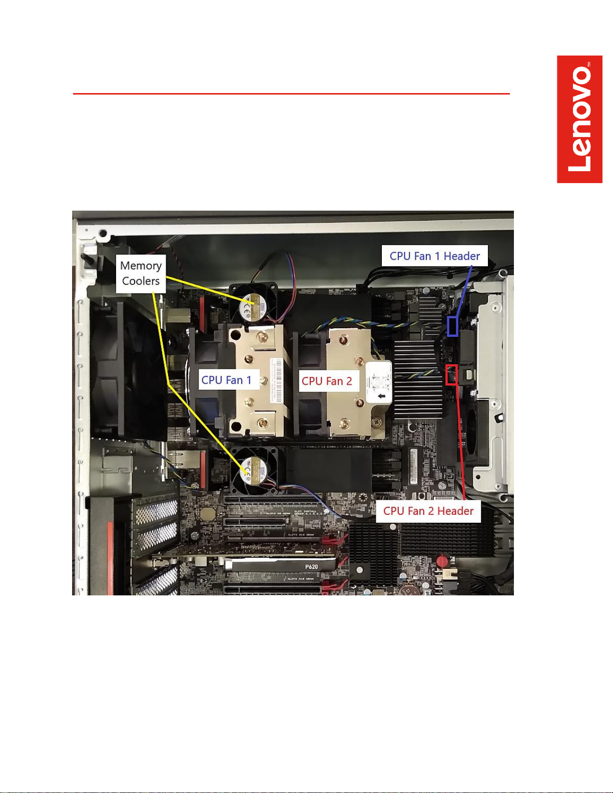
Section 1 – Key Components and Locations
Page 5
5
Section 2 – Memory Cooler Removal and
Installation Process
All P620 systems ship with fan assemblies that sit over the memory DIMMs to
provide sufficient airflow to those components. Follow the steps below to remove
or install the memory cooler assemblies. Note that removing the memory cooler
assemblies will likely make it easier when installing or uninstalling the CPU.
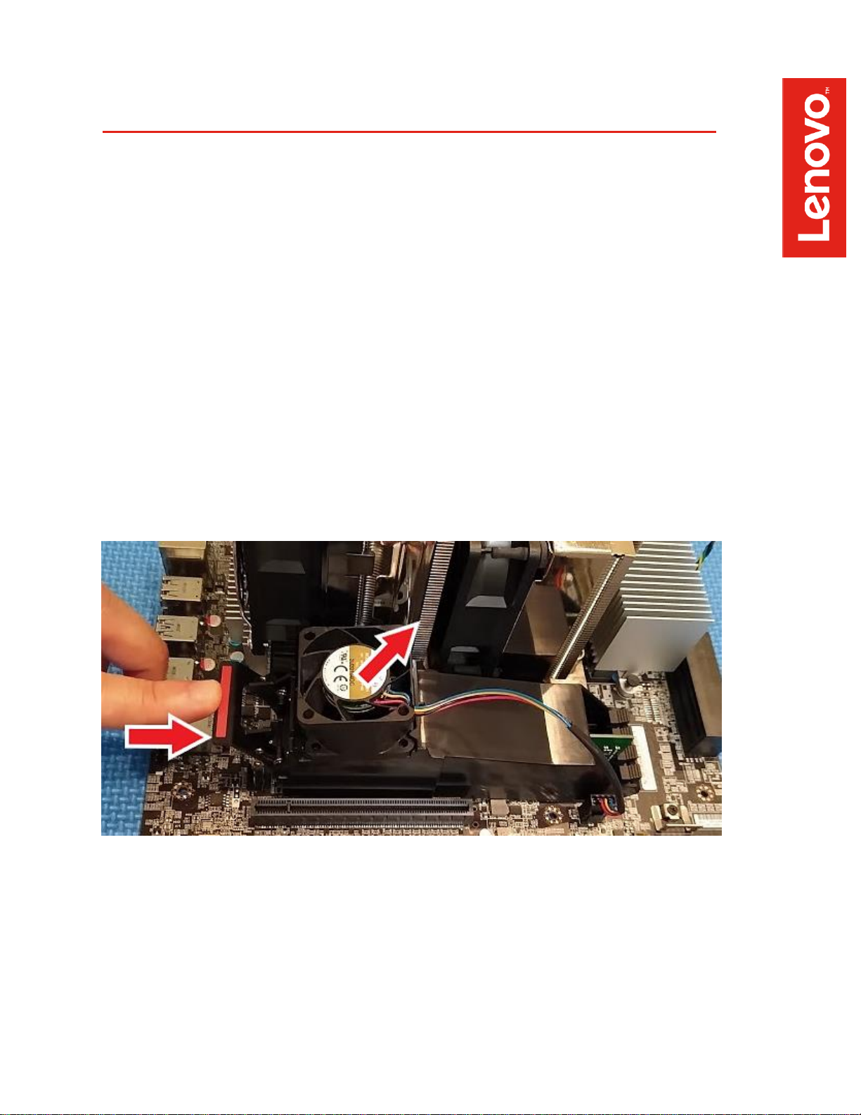
To remove the memory cooler assembly:
• Unplug the 4-pin fan connector noting the specific location of the header on
the motherboard.
• Push on the spring-loaded tab on the side of the memory DIMM slots, then
lift and rotate the assembly off the DIMM slots using a clockwise motion.
• Do this for each memory cooler assembly installed on the system.
Page 6

6
To install the memory cooler assembly:
• Before starting the installation process, ensure all latches for any unused
memory DIMM slots are in the upright/closed position.
• Orient the memory cooler assembly such that the fan is closest to the rear
of the system.
• Hook the front facing edge of the assembly over the memory DIMM slot
latches.
• Rotate the assembly in a counter-clockwise direction down to the
motherboard.
• Engage the spring-loaded latch on the memory cooler such that it hooks
onto the memory DIMM slot latches (closest to the fan). A slight pull upward
on the assembly will confirm that it has engaged properly.
• Reconnect the 4-pin fan header to the appropriate location on the
motherboard.
Page 7

7
Section 3 – CPU Removal and Installation
Process
Important Note: As CPUs are very sensitive electronic devices, it is
recommended that users properly ground themselves using the necessary
equipment before attempting any of the procedures outlined below.
It is recommended that users attempting to remove or install a CPU in the P620
platform first remove the memory cooler assemblies to make more working room
for CPU installation. Please refer to Section 2 in this document.
CPU Removal
1. Remove the CPU heatsink from the motherboard.
• Unplug the 4-wire fan connectors for CPU FAN1 and CPU FAN2,
noting the specific location for each connector.
• Unscrew the four retaining screws in the order specified (1 – 2 – 3 –
4). Note that a 6” Phillips #2 screwdriver/bit is recommended in order
to be able to access the retaining screws located directly under the
heatsink fins via the access holes in the heatsink.
• Carefully lift off the CPU heatsink assembly.
Page 8

8
2. Open the CPU socket
• Release the socket force frame by using a Torx T-20 screwdriver/bit
to unscrew the three fasteners. Unscrew the fasteners in sequence 3
– 2 – 1 to release the force frame. Note that the force frame is spring
loaded, so it will pop up when the final fastener is unscrewed.
Page 9

9
3. Separate the CPU from the socket
• Lift the CPU tray assembly using the blue tabs to remove the CPU
from the socket on the motherboard
Page 10

10
4. Remove the CPU and carrier frame from the CPU tray
• With the CPU tray in an upright position, careful pull on the tab on the
orange carrier frame and slide the carrier frame + CPU assembly out
of the CPU tray.
• Use caution to avoid touching the electrical contact points on the
bottom of the CPU
Page 11

11
CPU Installation
1. Install CPU and carrier frame to CPU tray.
• With the CPU socket fully open and the CPU tray in the upright
position, carefully grasp the CPU carrier frame and insert it into the
CPU tray.
• The tab on the orange carrier frame should be up and facing away
from the socket to ensure correct CPU orientation.
• Ensure the edges of the carrier frame engage the small black rails in
the CPU tray
• Push the CPU + carrier frame assembly down into the CPU tray until
the tabs of the frame line up with the notches of the CPU tray.
Page 12

12
2. Install CPU to the socket.
• Push on the CPU tray using the blue tabs to securely seat the CPU
tray assembly into the socket. A small click can be heard and felt
when the assembly is properly seated.
Page 13

13
3. Close and secure the CPU socket.
• Lower the spring loaded force frame assembly to the closed position.
• Secure the three force frame fasteners using the Torx T-20
screwdriver/bit following the sequence 1 – 2 – 3.
• Tighten each fastener fully to 14lbf-in (inch pounds) or 1.5Nm before
moving on to the next fastener.
Page 14

14
4. Reinstall CPU heatsink.
• If necessary, remove any existing thermal interface material (thermal
grease) from the base of the heatsink. New thermal interface
material can be applied to the CPU heatspreader directly in the
pattern shown below.
• Align the CPU heatsink with the CPU socket ensuring the fans are
facing the rear of the system.
• Secure the heatsink using the four retention screws. Screws should
be secured in the sequence shown (1 – 2 – 3 – 4), and tightened to
5lbf-in (inch pounds).
• Reconnect the 4-wire connectors for FAN1 and FAN2 to the
appropriate headers on the motherboard.
Page 15

15
5. Reinstall the memory cooler.
• Refer to Section 2 of this document for more detail.
Tip: Access the link below for a helpful video walkthrough of the CPU installation
process. The video is specific for the AMD Threadripper CPU, but it also applies to
the Threadripper Pro CPU as well since they utilize the same CPU socket.
https://www.amd.com/en/support/kb/faq/cpu-install-tr
Page 16

16
Section 4 – Revision History
Version
Date
Author
Changes/Updates
1.0
8/31/2020
Cory Chapman
Initial launch release
 Loading...