


P620
User Guide

Read this first
Before using this documentation and the product it supports, ensure that you read and understand the
following:
• Appendix A “Important safety information” on page 105
• Safety and Warranty Guide
• Setup Guide
Second Edition (February 2021)
© Copyright Lenovo 2020, 2021.
LIMITED AND RESTRICTED RIGHTS NOTICE: If data or software is delivered pursuant to a General Services
Administration “GSA” contract, use, reproduction, or disclosure is subject to restrictions set forth in Contract No. GS35F-05925.

Contents
About this documentation . . . . . . . . iii
Chapter 1. Meet your computer. . . . . 1
Front . . . . . . . . . . . . . . . . . . . . 1
Rear . . . . . . . . . . . . . . . . . . . . 3
System board . . . . . . . . . . . . . . . . 4
Internal storage drives . . . . . . . . . . . . . 7
Features and specifications . . . . . . . . . . . 9
Statement on USB transfer rate . . . . . . . 10
Chapter 2. Get started with your
computer . . . . . . . . . . . . . . . . 11
Get started with Windows 10 . . . . . . . . . 11
Windows account . . . . . . . . . . . . 11
Windows user interface . . . . . . . . . . 12
Connect to networks. . . . . . . . . . . . . 13
Connect to the wired Ethernet . . . . . . . 13
Connect to Wi-Fi networks (for selected
models) . . . . . . . . . . . . . . . . 13
Use the Vantage app . . . . . . . . . . . . . 13
Use multimedia . . . . . . . . . . . . . . . 14
Use audio . . . . . . . . . . . . . . . 14
Connect to an external display . . . . . . . 14
Chapter 3. Explore your computer . . 17
Manage power . . . . . . . . . . . . . . . 17
Set power button behaviors . . . . . . . . 17
Set the power plan . . . . . . . . . . . . 17
Transfer data . . . . . . . . . . . . . . . . 17
Connect to a Bluetooth-enabled device (for
selected models) . . . . . . . . . . . . 17
Use the optical drive (for selected models) . . 18
Use a media card (for selected models) . . . . 18
Purchase accessories . . . . . . . . . . . . 19
Chapter 4. Secure your computer
and information . . . . . . . . . . . . 21
Lock the computer . . . . . . . . . . . . . 21
Use passwords . . . . . . . . . . . . . . . 22
Use software security solutions. . . . . . . . . 23
Use firewalls . . . . . . . . . . . . . . 23
Use computrace Agent software embedded in
firmware (for selected models) . . . . . . . 24
Use BIOS security solutions . . . . . . . . . . 24
Erase all storage drive data . . . . . . . . 24
Use the cover presence switch . . . . . . . 24
Use Smart USB Protection. . . . . . . . . 25
Chapter 5. UEFI BIOS . . . . . . . . . 27
What is UEFI BIOS. . . . . . . . . . . . . . 27
Enter the BIOS menu. . . . . . . . . . . . . 27
Navigate in the BIOS interface . . . . . . . . . 27
Change the display language of UEFI BIOS . . . . 27
Change the display mode of UEFI BIOS . . . . . 28
Set the system date and time . . . . . . . . . 28
Change the startup sequence . . . . . . . . . 28
Enable or disable the configuration change
detection feature . . . . . . . . . . . . . . 29
Enable or disable the automatic power-on
feature . . . . . . . . . . . . . . . . . . 29
Enable or disable the ErP LPS compliance mode . . 29
Change the fan speed level . . . . . . . . . . 30
CPU locking when PSB is enabled . . . . . . . 30
Change BIOS settings before installing a new
operating system . . . . . . . . . . . . . . 30
Update UEFI BIOS. . . . . . . . . . . . . . 30
UEFI BIOS self-healing recovery . . . . . . . . 31
Recover from a BIOS update failure . . . . . . . 31
Clear CMOS . . . . . . . . . . . . . . . . 31
Chapter 6. RAID . . . . . . . . . . . . 33
What is RAID . . . . . . . . . . . . . . . . 33
Select RAID mode . . . . . . . . . . . . . . 33
RAID Levels . . . . . . . . . . . . . . . . 33
Configure RAID with RAIDXpert2 Configuration
Utility . . . . . . . . . . . . . . . . . . . 34
Chapter 7. Troubleshooting,
diagnostics, and recovery . . . . . . . 37
Basic procedure for resolving computer
problems . . . . . . . . . . . . . . . . . 37
Troubleshooting . . . . . . . . . . . . . . 37
Startup problems . . . . . . . . . . . . 37
Audio problems . . . . . . . . . . . . . 38
Network problems . . . . . . . . . . . . 38
Performance problems . . . . . . . . . . 41
Storage drive problems . . . . . . . . . . 42
CD or DVD problems . . . . . . . . . . . 42
Serial connector problems. . . . . . . . . 43
USB device problems . . . . . . . . . . 43
Software problems. . . . . . . . . . . . 44
Diagnostics . . . . . . . . . . . . . . . . 44
Lenovo diagnostic tools. . . . . . . . . . 44
ThinkStation Diagnostics . . . . . . . . . 44
Lenovo PC Diagnostics . . . . . . . . . . 45
Recovery . . . . . . . . . . . . . . . . . 45
© Copyright Lenovo 2020, 2021 i

Restore system files and settings to an earlier
point . . . . . . . . . . . . . . . . . 45
Restore your files from a backup . . . . . . 45
Reset your computer . . . . . . . . . . . 45
Use advanced options . . . . . . . . . . 46
Windows automatic recovery. . . . . . . . 46
Create and use a recovery USB device . . . . 46
Update the device driver . . . . . . . . . 47
Chapter 8. CRU replacement . . . . . 49
What are CRUs . . . . . . . . . . . . . . . 49
Replace a CRU . . . . . . . . . . . . . . . 50
ID badge. . . . . . . . . . . . . . . . 50
Computer cover . . . . . . . . . . . . . 52
Device in the flex bay . . . . . . . . . . . 56
Storage drive in the front-access storage
enclosure . . . . . . . . . . . . . . . 59
Device in the multi-drive conversion kit . . . . 62
Cover presence switch . . . . . . . . . . 67
Storage drive in a storage drive bay . . . . . 68
Storage drive cage. . . . . . . . . . . . 71
M.2 solid-state drive . . . . . . . . . . . 74
Power supply assembly . . . . . . . . . . 80
PCIe card . . . . . . . . . . . . . . . 81
Full-length PCIe card . . . . . . . . . . . 85
Front fan assembly. . . . . . . . . . . . 87
Rear fan assembly . . . . . . . . . . . . 89
Memory module active cooler and duct. . . . 90
Memory module . . . . . . . . . . . . . 91
Coin-cell battery. . . . . . . . . . . . . 93
Wi-Fi units . . . . . . . . . . . . . . . 95
Chapter 9. Help and support . . . . . 101
Self-help resources . . . . . . . . . . . . . 101
Call Lenovo . . . . . . . . . . . . . . . . 102
Before you contact Lenovo . . . . . . . . 102
Lenovo Customer Support Center . . . . . . 103
Purchase additional services. . . . . . . . . . 103
Appendix A. Important safety
information . . . . . . . . . . . . . . . 105
Appendix B. System memory
speed. . . . . . . . . . . . . . . . . . 119
Appendix C. Accessibility and
ergonomic information . . . . . . . . 121
Appendix D. Supplemental
information about the Ubuntu operating
system . . . . . . . . . . . . . . . . . 125
Appendix E. Compliance and TCO
Certified information. . . . . . . . . . 127
Appendix F. Notices and
trademarks . . . . . . . . . . . . . . . 137
ii P620 User Guide

About this documentation
• Illustrations in this documentation might look different from your product.
• Depending on the model, some optional accessories, features, and software programs might not be
available on your computer.
• Depending on the version of operating systems and programs, some user interface instructions might not
be applicable to your computer.
• Documentation content is subject to change without notice. Lenovo makes constant improvements on the
documentation of your computer, including this User Guide. To get the latest documentation, go to:
https://pcsupport.lenovo.com
• Microsoft® makes periodic feature changes to the Windows® operating system through Windows Update.
As a result, some information in this documentation might become outdated. Refer to Microsoft resources
for the latest information.
© Copyright Lenovo 2020, 2021 iii

iv P620 User Guide
Chapter 1. Meet your computer
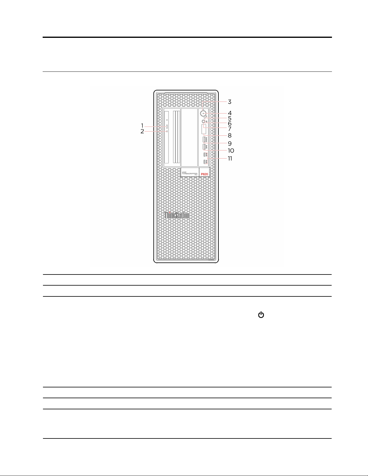
Front
1. Optical drive eject button* Eject the optical drive tray.
2. Optical drive activity indicator* This indicator is on when the optical drive is in use.
Press to turn on the computer.
To turn off the computer, open the Start menu, click
Shut down.
The indicator in the power button shows the system status of your computer.
3. Power button
4. Power indicator
5. Storage drive activity indicator This indicator is on when the storage drive is in use.
6. Photoelectric sensor*
© Copyright Lenovo 2020, 2021 1
• Blinking for three times: The computer is initially connected to power.
• On: The computer is on.
• Off: The computer is off or in hibernation mode.
• Blinking rapidly: The computer is entering sleep or hibernation mode.
• Blinking slowly: The computer is in sleep mode.
This indicator is on when the computer is turned on.
This sensor receives the flash light sent by the Lenovo PC Diagnostics application
installed in the smartphone. Then, the photoelectric sensor triggers the computer
to send the tune of the detected error to the smartphone for users to decode the
error.
Power, and then select

7. Headset connector
Connect a headset or headphones to your computer.
8. Four-digit diagnostic display
9. USB 3.2 connector Gen 2 (with
charging function)
10. USB 3.2 connector Gen 2
11. USB-C
®
(3.2 Gen 2)
connector
* for selected models
Display a four-digit error code when an issue or error is detected. You can check
the error code at
https://thinkworkstationsoftware.com/diags.
• Charge USB- compatible devices with the output voltage and current of 5 V
and 2.1 A.
• Enable you to experience higher data transfer rate when you connect USBcompatible devices, such as a USB keyboard, USB mouse, USB storage
device, or USB printer.
Enable you to experience higher data transfer rate when you connect USBcompatible devices, such as a USB keyboard, USB mouse, USB storage device,
or USB printer.
• Charge USB-C compatible devices with the output voltage and current of 5 V
and 3 A.
• Transfer data at USB 3.2 speed, up to 10 Gbps.
2
P620 User Guide
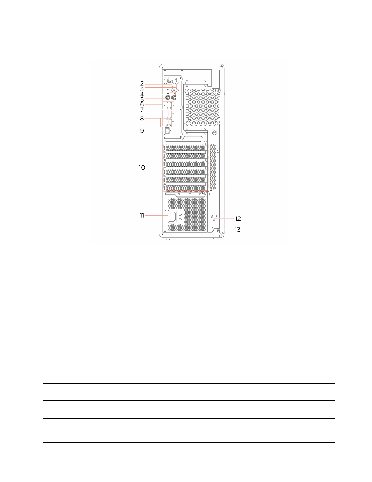
Rear
1. Microphone connector
2. Audio line-out connector
3. Audio line-in connector
4. Serial connector*
5. PS/2 keyboard connector* Connect a keyboard that uses a Personal System/2 (PS/2) keyboard connector.
6. PS/2 mouse connector*
7. USB 2.0 connectors
8. USB 3.2 connectors Gen 2
Connect a microphone to your computer when you want to record sound or
interact with the computer using speech recognition software.
Send audio signals from the computer to external devices, such as powered
stereo speakers, headphones, or multimedia keyboards. To connect a stereo
system or other external recording device, connect a cable between the audio
line-in connector of the device and the audio line-out connector of the computer.
Note: If your computer has both an audio line-out connector and a headset or
headphone connector, always use the headset or headphone connector for
earphones, headphones, or a headset. The headphone connector does not
support headset microphones.
Receive audio signals from an external audio device, such as a stereo system. To
connect an external audio device, connect a cable between the audio line-out
connector of the device and the audio line-in connector of the computer.
Connect an external modem, a serial printer, or other devices that use a serial
connector.
Connect a mouse, a trackball, or other pointing devices that use a PS/2 mouse
connector.
Connect USB-compatible devices, such as a USB keyboard, USB mouse, USB
storage device, or USB printer.
Enable you to experience higher data transfer rate when you connect USBcompatible devices, such as a USB keyboard, USB mouse, USB storage device,
or USB printer.
Chapter 1. Meet your computer 3

9. Ethernet connector
10. PCI-Express card area
Connect to a local area network (LAN). When the green indicator is on, the
computer is connected to a LAN. When the yellow indicator blinks, data is being
transmitted.
Install PCI-Express cards into this area to improve the operating performance of
the computer. Depending on the computer model, the connectors in this area
vary.
11. Power cord connector
12. Key-nest slots
13. Security-lock slot
Connect the power cord to your computer for power supply.
Install the key holder that comes with the computer-cover-lock key to the key-nest
slots.
Lock your computer to a desk, table, or other fixtures through a Kensington-style
cable lock.
* for selected models
System board
Note: The system board might look slightly different from the illustration.
4
P620 User Guide
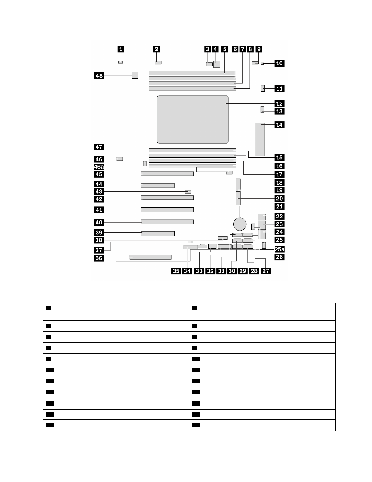
Figure 1. System board part locations
1 Cover presence switch connector (intrusion switch
2 Memory fan connector 1
connector)
3 Optical-drive fan connector 2 4 4-pin power connector (for optical drive)
5 Memory slot 1 6 Memory slot 2
7 Memory slot 3 8 Memory slot 4
9 Optical-drive fan connector
11 Microprocessor fan connector 1
13 Microprocessor fan connector 2
15 Memory slot 5 16 Memory slot 6
17 Memory slot 7 18 Memory slot 8
19 M.2 solid-state drive slot 1 20 M.2 solid-state drive slot 2
21 Coin-cell battery 22 4-pin power connector (for storage drive)
10 Thermal-sensor connector
12 Microprocessor
14 Front input/output connector
Chapter 1. Meet your computer 5
23 8-pin power connector (for graphics card) 24 8-pin power connector (for graphics card)
25 / 25a Front-fan-assembly connector 26 eSATA / SATA 6 connector
27 SATA 4 connector 28 SATA 2 connector
29 SATA 1 connector 30 SATA 3 connector
31 SATA 5 connector 32 Media card reader (MCR) header
33 Internal USB 3.2 Gen 2 connector 34 Alternative Trusted Platform Module (TPM) header
35 Thunderbolt™ control connector 36 Power supply connector
37 Internal-storage-drive activity indicator connector
39 PCIe 4.0 x8 card slot 6 40 PCIe 4.0 x16 card slot 5
41 PCIe 4.0 x16 card slot 4 42 PCIe 4.0 x16 card slot 3
43 Clear CMOS / Recovery jumper 44 PCIe 4.0 x8 card slot 2
45 PCIe 4.0 x 16 card slot 1 46 / 46a Memory fan connector 2
47 Rear-fan-assembly connector
38 Internal USB 2.0 connector
48 Serial port (COM) connector
6 P620 User Guide
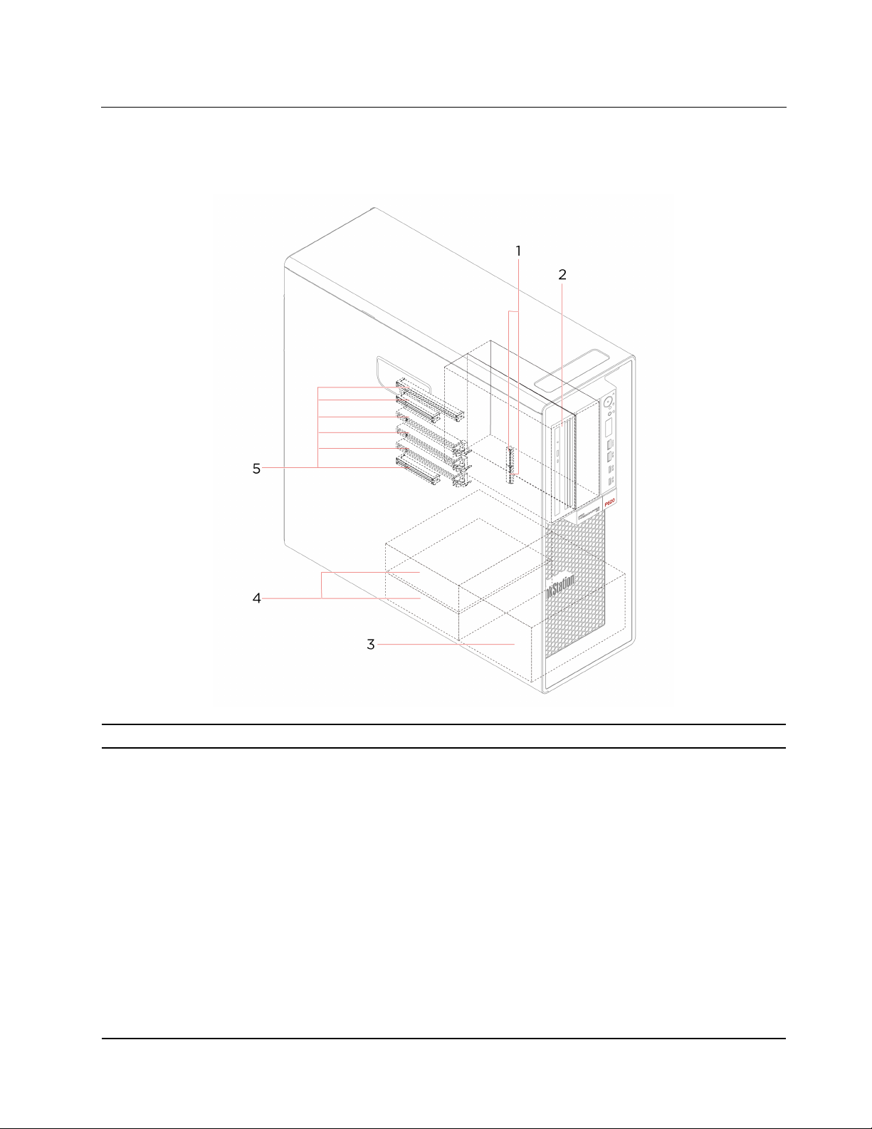
Internal storage drives
Internal storage drives are devices that your computer uses to read and store data. You can add drives to
your computer to increase storage capacity and enable your computer to read other types of media.
1. M.2 solid-state drive slots One or two M.2 solid-state drives are installed in selected models.
Depending on your computer model, the following devices might be installed in
the flex bay:
• Flex module
Depending on your computer model, the following parts might be installed in
the flex module:
– 15-in-1 card reader
2. Flex bay
– Slim optical drive
• Front-access storage enclosure
• Multi-drive conversion kit
Depending on your computer model, the following parts might be installed in
the multi-drive conversion kit:
– Internal storage drive
– Slim optical drive
• Slim-optical-drive adapter
Chapter 1. Meet your computer 7

You can install hard disk drives in the storage drive bays.
3. Storage drive bays*
4. Storage drive bays You can install hard disk drives in the storage drive bays.
Note: If you want to install storage drives into the optional-storage-drive bays,
contact the Lenovo Customer Support Center for help.
5. PCIe slots
* for selected models
You can install compatible PCIe cards and PCIe solid-state drives in the PCIe card
slots.
8
P620 User Guide

Features and specifications
• Width: 165 mm (6.5 inches)
Dimensions
Weight (without the packaging) Maximum configuration as shipped: 24 kg (52.91 lb)
Hardware configuration
Power supply 1000-watt automatic voltage-sensing power supply
• Height: 446 mm (17.6 inches)
• Depth: 455 mm (17.9 inches)
1. Right-click the Start button to open the Start context menu.
2. Click Device Manager. Type the administrator password or provide
confirmation if prompted.
Electrical input
Microprocessor
Memory
Storage device
Video features
• Input voltage: From 100 V ac to 240 V ac
• Input frequency: 50/60 Hz
To view the microprocessor information of your computer, right-click the Start
button and then click System.
Up to eight double data rate 4 (DDR4) error correction code (ECC) registered dual
inline memory modules (RDIMMs)
• Hard disk drive
• M.2 solid-state drive*
• Slim optical drive*
• 15-in-1 media card*
To view the storage drive capacity of your computer, right-click the Start button
to open the Start context menu and then click Disk Management.
Note: The storage drive capacity indicated by the system is less than the nominal
capacity.
• PCIe x16 card slots on the system board for a discrete graphics card
• Video connectors on a discrete graphics card:
– DVI connector
– DisplayPort connector
– Mini DisplayPort connector
Audio features
The integrated audio card supports the following:
• Audio line-in connector
• Audio line-out connector
• Headset connector
• Internal speaker
• Microphone connector
Chapter 1. Meet your computer 9

• Flex bay
• Storage drive bays
Expansion
Network features
• M.2 solid-state drive slots
• Memory slots
• PCI Express slots
• Bluetooth*
• Ethernet LAN
• Wireless LAN*
* for selected models
Statement on USB transfer rate
Depending on many factors such as the processing capability of the host and peripheral devices, file
attributes, and other factors related to system configuration and operating environments, the actual transfer
rate using the various USB connectors on this device will vary and will be slower than the data rate listed
below for each corresponding device.
USB device Data rate (Gbit/s)
3.2 Gen 1 / 3.1 Gen 1
3.2 Gen 2 / 3.1 Gen 2
3.2 Gen 2 × 2
Thunderbolt 3 40
Thunderbolt 4 40
5
10
20
10 P620 User Guide

Chapter 2. Get started with your computer
Get started with Windows 10
Learn the basics of Windows 10 and start working with it right away. For more information about Windows
10, see the Windows help information.
Windows account
A user account is required to use the Windows operating system. It can either be a Windows user account or
a Microsoft account.
Windows user account
When you start Windows for the first time, you are prompted to create a Windows user account. This first
account you created is of the “Administrator” type. With an Administrator account, you can create additional
user accounts or change account types by doing the following:
1. Open the Start menu and select Settings ➙ Accounts ➙ Family & other users.
2. Follow the on-screen instructions.
Microsoft account
You can also log in to the Windows operating system with a Microsoft account.
To create a Microsoft account, go to the Microsoft sign-up page at
screen instructions.
With a Microsoft account, you can:
• Enjoy one-time signing in if you are using other Microsoft services, such as OneDrive, Skype, and Outlook.
com.
• Sync personalized settings across other Windows-based devices.
https://signup.live.com and follow the on-
© Copyright Lenovo 2020, 2021 11
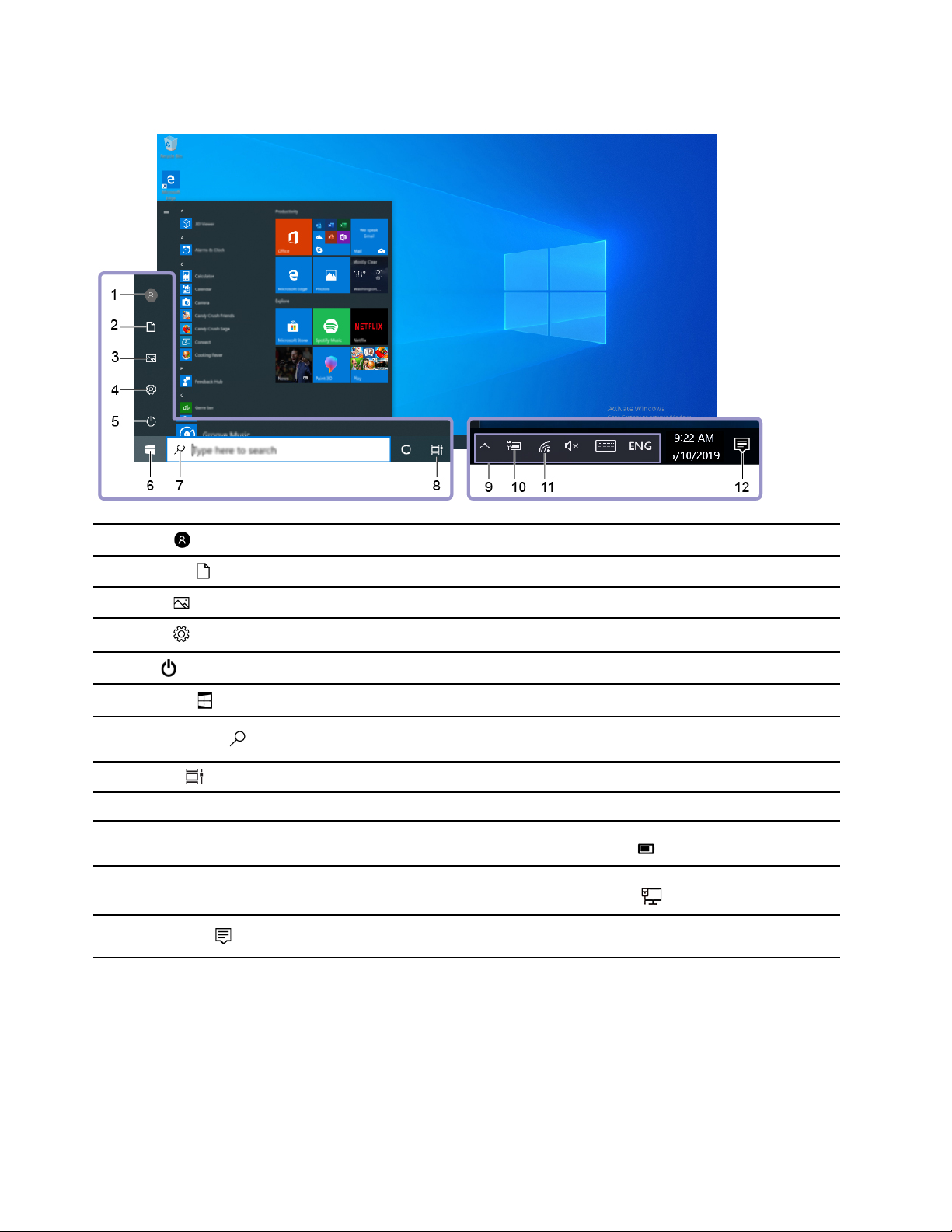
Windows user interface
1. Account
2. Documents
3. Pictures
4. Settings
5. Power
6. Start button
7. Windows Search
8. Task View
9. Windows notification area
10. Battery status icon
11. Network icon
12. Action center
Change account settings, lock the computer, or sign out from the current account.
Open the Documents folder, a default folder to save your received files.
Open the Pictures folder, a default folder to save your received pictures.
Launch Settings.
Shut down, restart, or put the computer into sleep mode.
Open the Start menu.
Type what you are looking for in the search box and get search results from your
computer and the Web.
Display all opened apps and switch among them.
Display notifications and status of some features.
Display power status and change battery or power settings. When your computer
is not connected to ac power, the icon changes to
Connect to an available wireless network and display the network status. When
connected to a wired network, the icon changes to
Display the latest notifications from apps and provide quick access to some
features.
Open the Start menu
• Click the Start button.
• Press the Windows logo key on the keyboard.
.
.
Open the Start context menu
Right-click the Start button.
12
P620 User Guide

Access Control Panel
• Open the Start menu and click Windows System ➙ Control Panel.
• Use Windows Search.
Launch an app
• Open the Start menu and select the app you want to launch.
• Use Windows Search.
Connect to networks
Your computer helps you connect to the world through a wired or wireless network.
Connect to the wired Ethernet
Connect your computer to a local network through the Ethernet connector on your computer with an
Ethernet cable.
Connect to Wi-Fi networks (for selected models)
If your computer includes a wireless LAN module, you can connect your computer to Wi-Fi® networks. The
wireless LAN module on your computer may support different standards. For some countries or regions, use
of 802.11ax may be disabled according to local regulations.
1. Click the network icon in the Windows notification area. A list of available wireless networks is displayed.
2. Select a network available for connection. Provide required information, if needed.
Use the Vantage app
The preinstalled Vantage app is a customized one-stop solution to help you maintain your computer with
automated updates and fixes, configure hardware settings, and get personalized support.
To access the Vantage app, type Vantage in the search box.
Key features
The Vantage app enables you to:
• Know the device status easily and customize device settings.
• Download and install UEFI BIOS, firmware and driver updates to keep your computer up-to-date.
• Monitor your computer health, and secure your computer against outside threats.
• Scan your computer hardware and diagnose hardware problems.
• Look up warranty status (online).
• Access User Guide and helpful articles.
Notes:
• The available features vary depending on the computer model.
• The Vantage app makes periodic updates of the features to keep improving your experience with your
computer. The description of features might be different from that on your actual user interface.
Chapter 2. Get started with your computer 13

Use multimedia
Use your computer for business or entertainment with the devices (such as a camera, a monitor, or
speakers).
Use audio
To enhance the audio experience, connect speakers, headphones, or a headset to the audio connector.
Adjust the volume
1. Click the volume icon in the Windows notification area on the taskbar.
2. Follow the on-screen instructions to adjust the volume. Click the speaker icon to mute the audio.
Change the sound settings
1. Go to Control Panel and view by category.
2. Click Hardware and Sound ➙ Sound.
3. Change the settings as you prefer.
Connect to an external display
Connect to a wired display
Connect your computer to a projector or a monitor through the video connectors on a discrete graphics card
installed in your computer to give presentations or expand your workspace.
If your computer cannot detect the external display, right-click an empty area of the desktop, and then click
Display settings ➙ Detect.
Connect to a wireless display
To use a wireless display, ensure that both your computer and the external display support the Miracast
feature.
• Open the Start menu, and then click Settings ➙ Devices ➙ Bluetooth & other devices ➙ Add
Bluetooth or other device. In the Add a device window, click Wireless display or dock. Then, follow the
instructions on the screen.
• Click the action center icon
display and follow the on-screen instructions.
Set the display mode
Right-click a blank area on the desktop and select Display settings. Then, select a display mode of your
preference from the Multiple displays menu.
• Duplicate these displays: Display the same video output on both your computer screen and an external
display.
• Extend these displays: Extend the video output from your computer display to an external display. You
can drag and move items between the two displays.
• Show only on 1: Display the video output only on your computer screen.
• Show only on 2: Display the video output only on an external display.
If you show programs using DirectDraw or Direct3D
video output.
in the Windows notification area and click Connect. Select the wireless
®
in full-screen mode, only the main display shows the
®
14
P620 User Guide

Change display settings
1. Right-click a blank area on the desktop and select Display settings.
2. Select the display that you want to configure.
3. Change display settings of your preference.
You can change the settings for both the computer display and the external display. For example, you can
define which one is the main display and which one is the secondary display. You also can change the
resolution and orientation.
Note: If you set a higher resolution for the computer display than the external display, only part of the screen
can be displayed on the external display.
Chapter 2. Get started with your computer 15

16 P620 User Guide

Chapter 3. Explore your computer
Manage power
Use the information in this section to achieve the best balance between performance and power efficiency.
Set power button behaviors
You can define what the power button does according to your preference. For example, by pressing the
power button, you can turn off the computer or put the computer to sleep or hibernation mode.
To change what the power button does:
1. Go to Control Panel and view by large icons or small icons.
2. Click Power Options ➙ Choose what the power buttons do.
3. Change the settings as you prefer.
Set the power plan
For ENERGY STAR® compliant computers, the following power plan takes effect when your computers have
been idle for a specified duration:
Table 1. Default power plan (when plugged into ac power)
• Turn off the display: After 10 minutes
• Put the computer to sleep: After 25 minutes
To awaken the computer from Sleep mode, press any key on your keyboard.
To reset the power plan to achieve the best balance between performance and power saving:
1. Go to Control Panel and view by large icons or small icons.
2. Click Power Options, and then choose or customize a power plan of your preference.
Transfer data
Quickly share your files using the built-in Bluetooth technology among devices with the same features. You
also can install a disc or media card to transfer data.
Connect to a Bluetooth-enabled device (for selected models)
You can connect all types of Bluetooth-enabled devices to your computer, such as a keyboard, a mouse, a
smartphone, or speakers. To ensure that the connection is successful, place the devices 10 meters (33 feet),
at most, from the computer.
1. Turn on Bluetooth on the computer.
a. Open the Start menu, and then click Settings ➙ Devices ➙ Bluetooth & other devices.
b. Turn on the Bluetooth switch.
2. Click Add Bluetooth or other device ➙ Bluetooth.
3. Select a Bluetooth device, and then follow the on-screen instructions.
© Copyright Lenovo 2020, 2021 17

Your Bluetooth device and computer will automatically connect the next time if the two devices are in range
of each other with Bluetooth turned on. You can use Bluetooth for data transfer or remote control and
communication.
Use the optical drive (for selected models)
If your computer has an optical drive, read the following information.
Know the type of your optical drive
1. Right-click the Start button to open the Start context menu.
2. Click Device Manager. Type the administrator password or provide confirmation, if prompted.
Install or remove a disc
1. With the computer on, press the eject/close button on the optical drive. The tray slides out of the drive.
2. Insert a disc into the tray or remove a disc from the tray, and then press the eject/close button again to
close the tray.
Note: If the tray does not slide out of the drive when you press the eject/close button, turn off the computer.
Then, insert a straightened paper clip into the emergency-eject hole adjacent to the eject/close button. Use
the emergency eject only in an emergency.
Record a disc
1. Insert a recordable disc into the optical drive that supports recording.
2. Do one of the following:
• Open the Start menu, and then click Settings ➙ Devices ➙ AutoPlay. Select or turn on Use
AutoPlay for all media and devices.
• Open Windows Media Player.
• Double-click the ISO file.
3. Follow the on-screen instructions.
Use a media card (for selected models)
If your computer has a SD-card slot, read the following information.
Install a media card
1. Locate the SD-card slot.
2. Ensure that the metal contacts on the card are facing the ones in the SD-card slot. Insert the card firmly
into the SD-card slot until it is secured in place.
Remove a media card
Attention: Before removing a media card, eject the card from the Windows operating system first.
Otherwise, data on the card might get corrupted or lost.
1. Click the triangular icon in the Windows notification area to show hidden icons. Then, right-click the
Safely Remove Hardware and Eject Media icon.
2. Select the corresponding item to eject the card from the Windows operating system.
3. Press the card and remove it from your computer. Store the card safely for future use.
18
P620 User Guide

Purchase accessories
Lenovo has a number of hardware accessories and upgrades to help expand the capabilities of your
computer. Options include memory modules, storage devices, network cards, power adapters, keyboards,
mice, and more.
To shop at Lenovo, go to
https://www.lenovo.com/accessories.
Chapter 3. Explore your computer 19

20 P620 User Guide
Chapter 4. Secure your computer and information
Lock the computer
Note: You are responsible for evaluating, selecting, and implementing the locking device and security
feature. Lenovo makes no comments, judgments, or warranties about the function, quality, or performance
of the locking device and security feature. You can purchase computer locks from Lenovo.
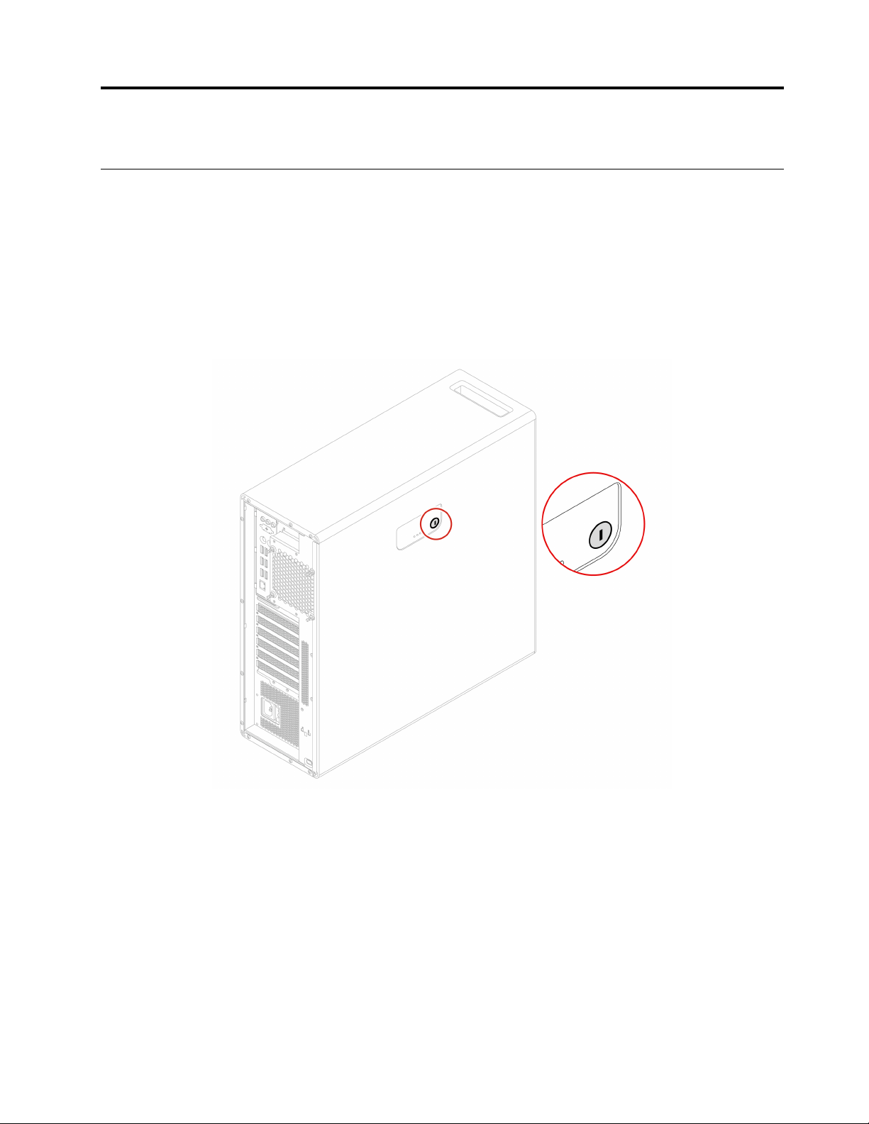
Key lock
Locking the computer cover through a key lock prevents unauthorized access to the inside of your computer.
The keys for the key lock are attached to the rear of the machine. For security, store the keys in a secure
place when you are not using them.
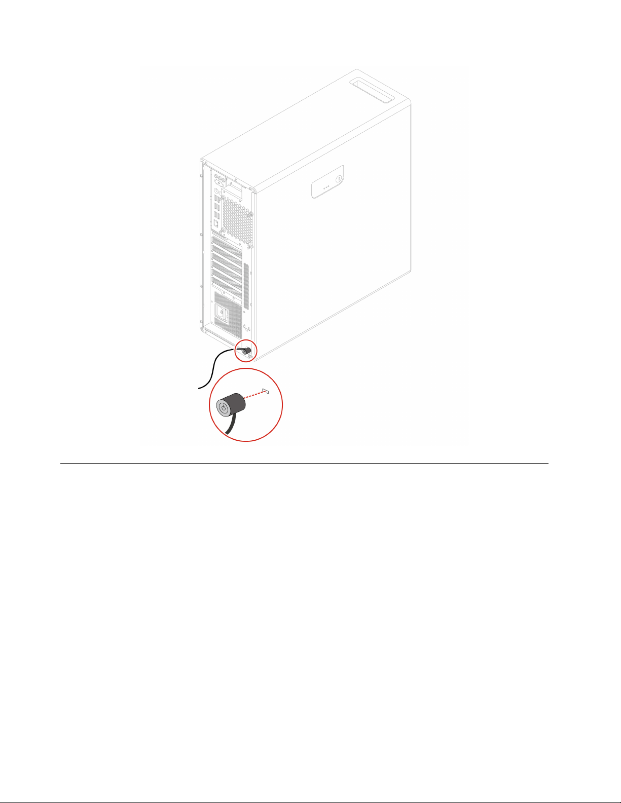
Kensington-style cable lock
Lock your computer to a desk, table, or other fixtures through a Kensington-style cable lock.
© Copyright Lenovo 2020, 2021 21
Use passwords
Password types
You can set the following passwords in UEFI (Unified Extensible Firmware Interface) BIOS (Basic Input/
Output System) to prevent unauthorized access to your computer. However, you are not prompted to enter
any UEFI BIOS password when your computer resumes from sleep mode.
• Power-on password
When a power-on password is set, you are prompted to enter a valid password each time the computer is
turned on. The computer cannot be used until the valid password is entered.
• Supervisor password
Setting a supervisor password deters unauthorized users from changing configuration settings. If you are
responsible for maintaining the configuration settings of several computers, you might want to set a
supervisor password.
When a supervisor password is set, you are prompted to enter a valid password each time you try to enter
the BIOS menu.
If both the power-on password and supervisor password are set, you can enter either password.
However, you must use your supervisor password to change any configuration settings.
• Hard disk password
22
P620 User Guide

Setting a hard disk password prevents unauthorized access to the data on the storage drive. When a hard
disk password is set, you are prompted to enter a valid password each time you try to access the storage
drive.
Note: After you set a hard disk password, your data on the storage drive is protected even if the storage
drive is removed from one computer and installed in another.
• System management password (for selected models)
You can enable the system management password to have the same authority as the supervisor
password to control security related features. To customize the authority of the system management
password through the UEFI BIOS menu:
1. Restart the computer. When the logo screen is displayed, press F1 or Fn+F1.
2. Select Security ➙ System Management Password Access Control.
3. Follow the on-screen instructions.
If you have set both the supervisor password and the system management password, the supervisor
password overrides the system management password.
Set, change, and remove a password
Before you start, print these instructions.
1. Restart the computer. When the logo screen is displayed, press F1 or Fn+F1.
2. Select Security.
3. Depending on the password type, select Set Supervisor Password, Set Power-On Password, Set
System Management Password, or Hard Disk Password and press Enter.
4. Follow the on-screen instructions to set, change, or remove a password.
5. Press F10 or Fn+F10 to save the changes and exit.
You should record your passwords and store them in a safe place. If you forget the passwords, see “Clear
CMOS” on page 31 to remove them by yourself. You can also contact a Lenovo-authorized service provider
to have the passwords removed.
Notes:
• If the supervisor password is forgotten, it might not be removed by clearing CMOS depending on your
BIOS settings.
• If the hard disk password is forgotten, Lenovo cannot remove the password or recover data from the
storage drive.
Use software security solutions
This section provides software solutions to secure your computer and information.
Use firewalls
A firewall can be hardware, software, or a combination of both depending on the level of security required.
Firewalls work on a set of rules to determine which inbound and outbound connections are authorized. If the
computer is preinstalled with a firewall program, it helps protect against computer Internet security threats,
unauthorized access, intrusions, and Internet attacks. It also protects your privacy. For more information
about how to use the firewall program, refer to the help system of your firewall program.
To use firewalls:
1. Go to Control Panel and view by large icons or small icons.
Chapter 4. Secure your computer and information 23

2. Click Windows Defender Firewall, and then follow the on-screen instructions.
Use computrace Agent software embedded in firmware (for selected models)
The Computrace Agent software is an IT asset management and computer theft recovery solution. The
software detects if changes have been made on the computer, such as hardware, software, or the computer
call-in location. You might have to purchase a subscription to activate the Computrace Agent software.
Use BIOS security solutions
This section provides BIOS solutions to secure your computer and information.
Erase all storage drive data
It is recommended that you erase all storage drive data before recycling a storage drive or the computer.
To erase all storage drive data:
1. Set a hard disk password for the storage drive you will recycle. See “Use passwords” on page 22.
2. Restart the computer. When the logo screen is displayed, press F1 or Fn+F1.
3. Select Security ➙ Hard Disk Password ➙ Security Erase HDD Data and press Enter.
4. Select the storage drive you will recycle and press Enter.
5. A message is displayed, prompting you to confirm the operation. Select Yes and press Enter. The
erasing process begins.
Note: During the erasing process, the power button and the keyboard are disabled.
6. After the erasing process is completed, a message is displayed, prompting you to reset the system.
Select Continue.
Note: Depending on the storage drive capacity, the erasing process will take half an hour to three hours.
7. After the resetting process is completed, one of the following will happen:
• If the data on the system storage drive is erased, you will be prompted that no operating system is
available.
• If the data on the non-system storage drive is erased, the computer restarts automatically.
Use the cover presence switch
The cover presence switch prevents the computer from logging in to the operating system when the
computer cover is not properly installed or closed.
To enable the cover presence switch connector on the system board:
1. Restart the computer. When the logo screen is displayed, press F1 or Fn+F1.
2. Select Security ➙ Cover Tamper Detected and press Enter.
3. Select Enabled and press Enter.
4. Press F10 or Fn+F10 to save the changes and exit.
When the cover presence switch connector on the system board is enabled, if the cover presence switch
detects that the computer cover is not correctly installed or closed, an error message will be displayed when
you turn on the computer. To bypass the error message and log in to the operating system:
1. Properly install or close the computer cover.
24
P620 User Guide

2. Enter the BIOS menu, save and then exit.
Use Smart USB Protection
The Smart USB Protection function is a security function that helps prevent data from being copied from the
computer to USB storage devices connected to the computer. You can set the Smart USB Protection
function to one of the following modes:
• Disabled (default setting): You can use the USB storage devices without limitation.
• Read Only: You cannot copy data from the computer to the USB storage devices. However, you can
access or modify data on the USB storage devices.
• No Access: You cannot access the USB storage devices from the computer.
To configure the Smart USB Protection function:
1. Restart the computer. When the logo screen is displayed, press F1 or Fn+F1.
2. Select Security ➙ Smart USB Protection and press Enter.
3. Select the desired setting and press Enter.
4. Press F10 or Fn+F10 to save the changes and exit.
Chapter 4. Secure your computer and information 25

26 P620 User Guide

Chapter 5. UEFI BIOS
This chapter provides information about configuring and updating UEFI BIOS, and clearing CMOS.
What is UEFI BIOS
Note: The operating system settings might override any similar settings in UEFI BIOS.
UEFI BIOS is the first program that the computer runs when the computer is turned on. UEFI BIOS initializes
the hardware components and loads the operating system and other programs. Your computer comes with a
setup program with which you can change UEFI BIOS settings.
Enter the BIOS menu
Restart the computer. When the logo screen is displayed, press F1 or Fn+F1 to enter the BIOS menu.
Note: If you have set BIOS passwords, enter the correct passwords when prompted. You also can select No
or press Esc to skip the password prompt and enter the BIOS menu. However, you cannot change the
system configurations that are protected by passwords.
Navigate in the BIOS interface
Attention: The default configurations are already optimized for you in boldface. Improper change of the
configurations might cause unexpected results.
Depending on your keyboard, you can navigate in the BIOS interface by pressing the following keys, or
combinations of Fn and the following keys:
F1 or Fn+F1
Esc or Fn+Esc Exit the submenu and return to the parent menu.
↑↓ or Fn+↑↓ Locate an item.
← → or Fn+← → Select a tab.
+/– or Fn++/– Change to a higher or lower value.
Enter Enter the selected tab or submenu.
F9 or Fn+F9 Restore to the default settings.
F10 or Fn+F10 Save your configuration and exit.
Display the General Help screen.
Change the display language of UEFI BIOS
UEFI BIOS supports three or four display languages: English, French, simplified Chinese, and Russian (for
selected models).
To change the display language of UEFI BIOS:
1. Select Main ➙ Language and press Enter.
2. Set the display language as desired.
© Copyright Lenovo 2020, 2021 27

Change the display mode of UEFI BIOS
You can use UEFI BIOS in the graphic mode or the text mode according to your needs.
To change the display mode of UEFI BIOS:
1. Restart the computer. When the logo screen is displayed, press F1 or Fn+F1.
2. Select Main ➙ Setup Mode Select and press Enter.
3. Set the display mode as desired.
Set the system date and time
1. Restart the computer. When the logo screen is displayed, press F1 or Fn+F1.
2. Select Main ➙ System Time & Date and press Enter.
3. Set the system date and time as desired.
4. Press F10 or Fn+F10 to save the changes and exit.
Change the startup sequence
If the computer does not start up from a device as expected, you can change the startup device sequence
permanently or select a temporary startup device.
Change the startup device sequence permanently
1. Depending on the type of the storage device, do one of the following:
• If the storage device is internal, go to step 2.
• If the storage device is a disc, ensure that the computer is on or turn on the computer. Then, insert
the disc into the optical drive.
• If the storage device is an external device other than a disc, connect the storage device to the
computer.
2. Restart the computer. When the logo screen is displayed, press F1 or Fn+F1.
3. Select Startup, and then follow the on-screen instructions to change the startup sequence.
4. Press F10 or Fn+F10 to save the changes and exit.
Select a temporary startup device
Note: Not all discs and storage drives are bootable.
1. Depending on the type of the storage device, do one of the following:
• If the storage device is internal, go to step 2.
• If the storage device is a disc, ensure that the computer is on or turn on the computer. Then, insert
the disc into the optical drive.
• If the storage device is an external device other than a disc, connect the storage device to the
computer.
2. Restart the computer. When the logo screen is displayed, press F12 or Fn+F12.
3. Select the storage device as desired and press Enter.
If you want to change the startup device sequence permanently, select Enter Setup on Startup Device Menu
and press Enter to enter the BIOS menu.
28
P620 User Guide

Enable or disable the configuration change detection feature
If you enable configuration change detection, when the POST detects configuration changes of some
hardware devices (such as storage drives or memory modules), an error message will be displayed when you
turn on the computer.
To enable or disable the configuration change detection feature:
1. Restart the computer. When the logo screen is displayed, press F1 or Fn+F1.
2. Select Security ➙ Configuration Change Detection and press Enter.
3. Enable or disable the feature as desired.
4. Press F10 or Fn+F10 to save the changes and exit.
To bypass the error message and log in to the operating system, press F2 or Fn+F2. To clear the error
message, enter the BIOS menu, save and then exit.
Enable or disable the automatic power-on feature
The Automatic Power On item in UEFI BIOS provides various options for you to make your computer start up
automatically.
To enable or disable the automatic power-on feature:
1. Restart the computer. When the logo screen is displayed, press F1 or Fn+F1.
2. Select Power ➙ Automatic Power On and press Enter.
3. Select the feature as desired and press Enter.
4. Enable or disable the feature as desired.
5. Press F10 or Fn+F10 to save the changes and exit.
Enable or disable the ErP LPS compliance mode
Lenovo computers meet the eco-design requirements of the ErP Lot 3 regulation. For more information, go
to:
https://www.lenovo.com/us/en/compliance/eco-declaration
You can enable the ErP LPS compliance mode to reduce the consumption of electricity when the computer
is off or in sleep mode. When the ErP LPS compliance mode is enabled, you can wake up the computer by
pressing the power button.
To enable or disable the ErP LPS compliance mode:
1. Restart the computer. When the logo screen is displayed, press F1 or Fn+F1.
2. Select Power ➙ Enhanced Power Saving Mode and press Enter.
3. Depending on whether you select Enabled or Disabled, do one of the following:
• If you select Enabled, press Enter. Then, select Power ➙ Automatic Power On and press Enter.
Check whether the Wake on LAN feature is disabled automatically. If no, disable it.
• If you select Disabled, press Enter. Then, go to the next step.
4. Press F10 or Fn+F10 to save the changes and exit.
To meet the off mode requirement of ErP compliance, you need to disable the Fast Startup function.
1. Go to Control Panel and view by large icons or small icons.
Chapter 5. UEFI BIOS 29

2. Click Power Options ➙ Choose what the power buttons do ➙ Change settings that are currently
unavailable.
3. Clear the Turn on fast startup (recommended) option from the Shutdown settings list.
Change the fan speed level
You can change the fan speed level, from level 1 to level 7, to adjust the thermal performance of your
computer. A higher fan speed level indicates better thermal performance with more noise.
To change the fan speed level:
1. Restart the computer. When the logo screen is displayed, press F1 or Fn+F1.
2. Select Power ➙ Fan Control Stepping and press Enter.
3. Set the fan speed level as desired.
4. Press F10 or Fn+F10 to save the changes and exit.
CPU locking when PSB is enabled
Platform Secure Boot is an AMD technology to enhance platform security. With this feature enabled in the
UEFI BIOS, after you replace the failing CPU with a new one and start the system, you will be prompted that
the new CPU will be locked and only work with the current computer model. You can select the option of
your preference.
Change BIOS settings before installing a new operating system
BIOS settings vary by operating system. Change the BIOS settings before installing a new operating system.
Microsoft constantly makes updates to the Windows 10 operating system. Before installing a particular
Windows 10 version, check the compatibility list for the Windows version. For details, go to:
https://support.lenovo.com/us/en/solutions/windows-support
To change the BIOS settings:
1. Restart the computer. When the logo screen is displayed, press F1 or Fn+F1.
2. From the main interface, select Security ➙ Secure Boot and press Enter.
3. Depending on the operating system to be installed, do one of the following:
• To install the Windows 10 (64-bit) and most of Linux operating system, select Enabled for Secure
Boot.
• To install an operating system that does not support secure boot, select Disabled for Secure Boot.
4. Press F10 or Fn+F10 to save the changes and exit.
Update UEFI BIOS
When you install a new program, device driver, or hardware component, you might need to update UEFI
BIOS. You can update the BIOS from your operating system or a flash update disc (supported only on
selected models).
Download and install the latest UEFI BIOS update package by one of the following methods:
• From the Vantage app:
Open the Vantage app to check the available update packages. If the latest UEFI BIOS update package is
available, follow the on-screen instructions to download and install the package.
30
P620 User Guide

• From the Lenovo Support Web site:
1. Go to
2. Download the flash BIOS update driver for the operating system version or the ISO image version
3. Print the installation instructions and follow the instructions to update the BIOS.
https://pcsupport.lenovo.com.
(used to create a flash update disc). Then, download the installation instructions for the flash BIOS
update driver you have downloaded.
UEFI BIOS self-healing recovery
When you update the UEFI BIOS, you might encounter a power failure or other critical operations that cause
the boot to crash. In this case, the UEFI BIOS self-healing recovery function is launched automatically to help
UEFI BIOS recover to boot, and help you save settings as much as possible. User input will be blocked and
no user operation is needed during the self-healing recovery process. Do not turn off your computer. System
will enter setup and display the progress when the primary image is recovered.
During the self-healing recovery process, the four-digit diagnostic display will indicate that self-healing
recovery is in progress and show the percentage of the progress alternatively. The whole process might take
you about 15 minutes.
If the self-healing recovery fails, the system will hang. You can contact a Lenovo-authorized service provider
to have the computer serviced.
Recover from a BIOS update failure
1. Remove all media from the drives and turn off all connected devices.
2. Insert the BIOS update disc into the optical drive, and then turn off the computer.
3. Disconnect all power cords from electrical outlets. Then, remove any parts that impede access to the
Clear CMOS/Recovery jumper.
4. Move the jumper from the standard position to the maintenance position.
5. Reconnect the power cords for the computer and the monitor to electrical outlets.
6. Turn on the computer and the monitor. When the computer beeps, the recovery process begins.
7. After the recovery process is completed, the computer will be turned off automatically.
Note: Depending on the computer model, the recovery process will take two to three minutes.
8. Disconnect all power cords from electrical outlets.
9. Move the jumper back to the standard position.
10. Reinstall all the parts that have been removed. Then, reconnect the power cords for the computer and
the monitor to electrical outlets.
11. Turn on the computer and the monitor. When the logo screen is displayed, press F1 or Fn+F1.
12. To prevent data loss, ensure that BIOS settings are restored to an earlier point. For BIOS configurations,
see Chapter 5 “UEFI BIOS” on page 27.
Clear CMOS
1. Remove all media from the drives and turn off all connected devices and the computer.
2. Disconnect all power cords from electrical outlets. Then, remove any parts that impede access to the
Clear CMOS/Recovery jumper.
3. Move the jumper from the standard position to the maintenance position.
4. Reconnect the power cords for the computer and the monitor to electrical outlets.
Chapter 5. UEFI BIOS 31

5. Turn on the computer and the monitor. When the computer beeps, wait for approximately 10 seconds.
6. Turn off the computer by holding the power button for approximately four seconds.
7. Disconnect all power cords from electrical outlets.
8. Move the jumper back to the standard position.
9. Reinstall all the parts that have been removed. Then, reconnect the power cords for the computer and
the monitor to electrical outlets.
10. Turn on the computer and the monitor. When the logo screen is displayed, press F1 or Fn+F1.
11. To prevent data loss, ensure that BIOS settings are restored to an earlier point. For BIOS configurations,
see Chapter 5 “UEFI BIOS” on page 27.
32
P620 User Guide

Chapter 6. RAID
What is RAID
Redundant Array of Independent Disks (RAID) is a technology that provides increased storage functions and
reliability through redundancy. It also can improve data storage reliability and fault tolerance compared with
single-drive storage systems. Data loss resulting from a drive failure can be prevented by reconstructing
missing data from the remaining drives.
When a group of independent physical storage drives is set up to use RAID technology, they are in a RAID
array. This array distributes data across multiple storage drives, but the array appears to the host computer
as one single storage unit. Creating and using RAID arrays provides high performance, such as the expedited
I/O performance, because several drives can be accessed simultaneously.
Select RAID mode
You can select the SATA RAID mode or NVMe RAID mode to configure RAID with RAIDXpert2 Configuration
Utility.
1. Do one of the following to select the SATA RAID mode or NVMe RAID mode:
• SATA RAID mode:
a. Restart the computer. When the logo screen is displayed, press F1 or Fn+F1.
b. Select Devices ➙ ATA Drive Setup ➙ Configure SATA as (AHCI/RAID).
c. Select RAID.
• NVMe RAID mode:
a. Restart the computer. When the logo screen is displayed, press F1 or Fn+F1.
b. Select Devices ➙ NVMe Setup ➙ NVMe RAID Mode (Enabled/Disabled).
c. Select Enabled.
2. Press F10 or Fn+F10 to save the changes and exit.
3. Restart the computer. When the logo screen is displayed, press F1 or Fn+F1.
4. Select Devices ➙ RAIDXpert2 Configuration Utility to select drives and configure RAID.
RAID Levels
CAUTION:
• Only one redundant RAID array is supported by AMD-RAID. RAID1, RAID5, and RAID10 are all
redundant arrays.
• The AMD-RAID does not support more than eight arrays, including Non-RAID array.
• Multiple operating systems are not supported on AMD-RAID Array. If the system is booted from an
AMD-RAID bootable array, the first array in the Arrays section must be the bootable array. The
system boots only from the first array in the Arrays section. Refer to “Configure RAID with
RAIDXpert2 Configuration Utility” on page 34 to find the first array by viewing array details and
checking the array number.
Your computer supports the following RAID levels:
• RAID 0: striped disk array
© Copyright Lenovo 2020, 2021 33

– Provide the highest performance but no data redundancy. Data in the array is striped (distributed)
across several disks.
– Support 2-8 disks.
– RAID 0 arrays are useful for holding information, such as the operating system paging file, where
performance is extremely important but redundancy is not.
• RAID 1: mirrored disk array
– Mirror data on a partition of one disk to another.
– Support 2 disks.
– RAID 1 arrays are useful when there are only two disks available and data integrity is more important
than storage capacity.
• RAID 5: block-level striped disk array with distributed parity
– Stripe data as well as parity, across all disks in the array.
– Support 3-8 disks.
– Offer exceptional read performance and redundancy.
• RAID 10: striped and mirrored disk array (a combination of RAID 0 and RAID 1)
– Combine mirrors and stripe sets. RAID 10 allows multiple disk failures, up to 1 failure in each mirror that
has been striped.
– Support 4, 6, or 8 disks.
– Offer better performance than a simple mirror because of the extra disks. Require twice the disk space
of RAID 1 to offer redundancy.
• Volume (JBOD):
– RAIDXpert2 Configuration Utility treats one or more disks or the unused space on a disk as a single
array.
– Support 1-8 disks.
– Provide the ability to link-together storage from one or several disks, regardless of the size of the space
on those disks. It is useful in scavenging space on disks unused by other disks in the array. It does not
provide performance benefits or data redundancy. Disk failure will result in data loss.
• RAIDABLE (also known as RAID Ready):
– Allow a RAIDABLE disk to be transformed later to RAID 0 or RAID 1.
– Support 1 disk.
Configure RAID with RAIDXpert2 Configuration Utility
If your computer comes with the RAIDXpert2 Configuration Utility , you can follow the sections below to
configure RAID.
Initialize disks
New disks and legacy disks must be initialized before they can be used to create an AMD-RAID array.
Initialization writes AMD-RAID configuration information (metadata) to a disk.
CAUTION:
• If a disk is part of an AMD-RAID array, the disk cannot be selected for initialization. To initialize the
disk anyway, delete the AMD-RAID array. Data on the disk is deleted during initialization so ensure
the correct disks are chosen to initialize.
• A legacy disk can contain valid data. When a legacy array is deleted, all data on the disk is lost.
34
P620 User Guide

1. Enter the RAIDXpert2 Configuration Utility menu. Then, use the arrow keys to select Physical Disk
Management and press Enter.
2. Use the arrow keys to select Select Physical Disk Operations and press Enter.
3. Use the arrow keys to select Initialize Disk and press Enter.
4. Select the disk(s) to initialize:
a. Use the arrow keys to select a disk and press the Space Bar or Enter. Multiple disks can be selected
using this method.
b. Use the arrow keys to select OK and press Enter.
c. Review the warning message. If you want to proceed, use the arrow keys to select YES and press
Enter.
Note: The Initialization process takes about 10 to 15 seconds. During initialization, a complete re-
scan of all channels is done automatically.
Create arrays
Arrays can be created after the disks are initialized:
1. Enter the RAIDXpert2 Configuration Utility menu. Then, use the arrow keys to select Array
Management and press Enter.
2. Use the arrow keys to select Create Array and press Enter.
3. Use the arrow keys to select Select RAID Level ➙ RAID Level and press Enter.
Note: Some of the RAID levels might not be displayed because the number of installed storage drives
varies.
4. Select the disks with which to create the array:
a. Use the arrow keys to select Physical Disks and press Enter.
b. Use the arrow keys to select desired disks and press the Space Bar or Enter.
c. Use the arrow keys to select Apply Changes and press Enter.
5. Refer to the table below for the default cache tag size (CTS).
Array type
HDD Array 64k
SSD Array 64k
All NVMe Array 256k
Default CTS
6. Use the arrow keys to select Read Cache Policy and press Enter. Select the desired read cache policy
and press Enter.
7. Use the arrow keys to select Write Cache Policy and press Enter. Select the desired write cache policy
and press Enter.
8. Use the arrow keys to select Create Array and press Enter.
Delete arrays
CAUTION:
• Deleting an array permanently destroys all data that is on the array. This action cannot be recalled
and it is very unlikely the data can be recovered.
• Do not delete the first array listed in the Arrays section, if it is the AMD-RAID bootable array. Doing
this deletes the operating system and AMD-RAID files.
Chapter 6. RAID 35

1. Enter the RAIDXpert2 Configuration Utility menu. Then, use the arrow keys to select Array
Management and press Enter.
2. Use the arrow keys to select Delete Arrays and press Enter.
3. Select the array(s) to delete:
a. Use the arrow keys to select the desired array or multiple arrays, then press the Space Bar or Enter
to change the option to Enabled for deletion.
b. If you want to select all of the arrays, use the arrow keys to select Check all and press Enter.
c. Use the arrow keys to select Delete Array and press the Space Bar or Enter.
d. Review the warning message. If you want to proceed, press the Space Bar or Enter.
e. Use the arrow keys to select Yes to delete arrays.
View array details
This option displays the details of an array. Nothing can be changed using this menu option. It is for
informational purposes only.
1. Enter the RAIDXpert2 Configuration Utility menu. Then, use the arrow keys to select Array
Management and press Enter.
2. Use the arrow keys to select Select Manage Array Properties and press Enter.
3. Use the arrow keys to select Select Array and press Enter. Select the desired array and press Enter.
4. Use the arrow keys to select View Associated Physical Disks and press Enter.
5. Press the Space Bar to select one of the members of the Array.
6. Use the arrow keys to select View Physical Disk Properties and press Enter.
7. Information about the array is displayed below Select Array header:
• Array number
• RAID level
• State
• Size
• Cache Tag Size
• Cache settings
• Associated physical disks
8. To view another array, press ESC twice and perform steps 2 through 7 again.
9. Press ESC to exit the main menu.
36
P620 User Guide

Chapter 7. Troubleshooting, diagnostics, and recovery
This chapter provides solutions to resolve computer problems. Use the basic procedure as a starting point
for resolving computer problems.
Basic procedure for resolving computer problems
Prerequisite
Before you start, read Appendix A “Important safety information” on page 105 and print the following
instructions.
1. Check that:
a. The cables for all connected devices are connected correctly and securely.
b. All components have been reassembled correctly.
c. All connected devices that require ac power are connected to properly grounded and working
electrical outlets.
d. All connected devices are enabled in UEFI BIOS.
2. Use an antivirus program (if any) to see if the computer has been infected by a virus. If the program
detects a virus, remove the virus.
3. See Chapter 7 “Troubleshooting, diagnostics, and recovery” on page 37 to resolve the problem you are
experiencing, run the diagnostic program, and recover your operating system.
4. If the problem persists, contact Lenovo. See Chapter 9 “Help and support” on page 101.
Troubleshooting
Use the troubleshooting information to find solutions to problems that have definite symptoms.
Startup problems
Problem Solution
• Ensure that the power cord is correctly connected to the rear of the
computer and to a working electrical outlet.
The computer does not start up when you
press the power button.
The operating system does not start up from
the correct storage drive or fails to start up
The computer beeps multiple times before
the operating system starts up.
• If the computer has a secondary power switch on the rear of the
computer, ensure that it is switched on.
• The power indicator on the front of the computer is on.
• The computer voltage matches the voltage available at the
electrical outlet for your country or region.
• Ensure that all storage drive signal cables and power cables are
connected correctly.
• Ensure that the storage drive the computer starts up from is listed
as the first startup device in UEFI BIOS.
• In rare cases, the storage drive with the operating system might get
corrupted or damaged. In such cases, you might need to replace
the storage drive.
Ensure that no keys are stuck.
© Copyright Lenovo 2020, 2021 37

Audio problems
Problem Solution
• If you are using powered external speakers that have an On/Off
control, ensure that:
– The On/Off control is set to the On position.
– The speaker power cable is connected to a properly grounded,
• If your external speakers have a volume control, ensure that the
volume is not set too low.
• Click the volume icon in the Windows notification area on the
taskbar. Check the speaker and volume settings. Do not mute the
speaker or set the volume at a very low level.
• If your computer has a front audio panel, ensure that the volume is
not set too low.
The audio cannot be heard on the Windows
operating system.
®
• Ensure that your external speakers (and headphones, if used) are
connected to the correct audio connector on the computer. Most
speaker cables are color-coded to match the audio connector.
Note: When external-speaker or headphone cables are connected
to the audio connector, the internal speaker, if present, is disabled.
In most cases, if an audio adapter is installed in one of the
expansion slots, the audio function built into the system board is
disabled. Therefore, you must use the audio connectors on the
audio adapter.
• Ensure that the program you are running is designed for use in the
Microsoft Windows operating system. If the program is designed to
run in DOS, the program does not use the Windows sound feature.
The program must be configured to use SoundBlaster Pro or
SoundBlaster emulation.
• Ensure that the audio device drivers are correctly installed.
functional ac electrical outlet.
The sound does not come from the headset
or headphones.
The sound comes from one of the external
speakers.
Select the headset or headphones as the default audio output device
in advanced sound settings.
• Ensure that the speaker cable is inserted completely into the
connector on the computer.
• Ensure that the cable that connects the left speaker to the right
speaker is securely connected.
• Ensure that the balance settings are set correctly.
1. Right-click the volume icon in the Windows notification area
2. Click the speaker icon on top of the volume control, and then
Network problems
Note: The Wi-Fi and Bluetooth features are optional.
on the taskbar. Then, click Open Volume Mixer and select the
desired speaker.
click the Levels tab.
38
P620 User Guide

Problem Solution
• Connect the cable from the Ethernet connector to the RJ45
connector of the hub.
• Enable the Ethernet LAN feature in UEFI BIOS.
• Enable the Ethernet LAN adapter.
1. Go to Control Panel and view by large icons or small icons.
2. Click Network and Sharing Center ➙ Change adapter
The computer cannot connect to an Ethernet
LAN.
3. Right-click the Ethernet LAN adapter icon and click Enable.
• Update or reinstall the Ethernet LAN driver.
• Install all networking software that is necessary for your network
environment. Check with your LAN administrator for the necessary
networking software.
• Set the same duplex for the switch port and the adapter. If you
configured the adapter for full duplex, ensure that the switch port is
also configured for full duplex. Setting a wrong duplex mode might
degrade performance, cause data loss, or result in lost
connections.
When a Gigabit Ethernet model computer is
used at a speed of 1000 Mbps, the Ethernet
LAN connection fails or errors occur.
The Wake On LAN (WOL) feature does not
work.
Connect the network cable to the Ethernet connector using Category
5 wiring and a 100 BASE-T hub/switch (not 100 BASE-X).
Enable the Wake On LAN feature in UEFI BIOS.
settings.
The Wi-Fi feature does not work.
• Enable the Wi-Fi feature in UEFI BIOS.
• Enable all Wi-Fi devices.
1. Right-click the Start button to open the Start context menu.
2. Click Device Manager. Type the administrator password or
provide confirmation, if prompted.
3. Expand Network adapters to display all network devices.
4. Right-click each Wi-Fi device, and then click Enable device.
• Enable the Wi-Fi feature in Windows Settings.
1. Open the Start menu.
2. Click Settings ➙ Network & Internet ➙ Wi-Fi.
3. Enable the Wi-Fi feature.
• Update or reinstall the Wi-Fi driver.
Chapter 7. Troubleshooting, diagnostics, and recovery 39

Problem Solution
• Enable the Bluetooth feature in UEFI BIOS.
• Enable all Bluetooth devices.
1. Right-click the Start button to open the Start context menu.
2. Click Device Manager. Type the administrator password or
3. Expand Bluetooth to display all Bluetooth devices. Right-click
The Bluetooth feature does not work.
4. Expand Network adapters to display all network devices.
• Turn on the Bluetooth radio.
1. Open the Start menu.
2. Click Settings ➙ Devices ➙ Bluetooth & other devices.
3. Turn on the Bluetooth switch to enable the Bluetooth feature.
• Update or reinstall the Bluetooth driver.
provide confirmation if prompted.
each Bluetooth device, and then click Enable device.
Right-click each Bluetooth device, and then click Enable
device.
Sound does not come from the Bluetooth
headset or headphones.
Select the Bluetooth headset or headphones as the default audio
output device in advanced sound settings.
40 P620 User Guide

Performance problems
Problem Solution
Note: Depending on the volume of the storage drives and amount of
data stored on the storage drives, the disk-defragmentation process
might take up to several hours.
1. Close any open programs and windows.
2. Open the Start menu.
Excessive fragmented files exist on the
storage drives.
The free storage drive space is insufficient.
3. Click Windows System ➙ File Explorer ➙ This PC.
4. Right-click your C drive and then click Properties.
5. Click the Tools tab.
6. Click Optimize. Select the drive as desired, and then click
7. Follow the on-screen instructions.
• Clean out your Inbox, Sent Items, and Deleted Items folders from
your e-mail application.
• Clean up your C drive.
1. Open the Start menu.
2. Click Windows System ➙ File Explorer ➙ This PC.
3. Right-click your C drive and then click Properties.
4. Check the amount of free space, and then click Disk Cleanup.
5. A list of unnecessary file categories is displayed. Select the
• Disable some Windows features or remove some unnecessary
programs.
1. Go to Control Panel and view by large icons or small icons.
2. Click Programs and Features.
3. Do one of the following:
Optimize.
category you want to delete, and then click OK.
– To disable some Windows features, click Turn Windows
features on or off. Follow the on-screen instructions.
– To remove some unnecessary programs, select the
program you want to remove, and then click Uninstall/
Change or Uninstall.
The free memory space is insufficient.
• Right-click a blank area on the taskbar and open Task Manager.
Then, end some tasks you are not performing.
• Install additional memory modules.
Chapter 7. Troubleshooting, diagnostics, and recovery 41

Storage drive problems
Problem Solution
• Ensure that the signal cables and power cables for all the storage
drives are connected correctly.
• Ensure that the computer is configured correctly to support the
storage drives.
Some or all storage drives are missing from
the BIOS menu.
– If the computer is installed with SATA storage drives, ensure
– If the computer is installed with SAS storage drives, ensure that
CD or DVD problems
Problem Solution
• Ensure that the optical drive supports the CD or DVD.
• Ensure that the disc is inserted correctly, with its label up.
• Ensure that the disc you are using is clean. To remove dust or
fingerprints, wipe the disc clean with a soft cloth from the center to
the outside. Wiping a disc in a circular motion might cause loss of
data.
A CD or DVD does not work.
• Ensure that the power cable and signal cable are securely
connected to the drive.
• Ensure that the disc you are using is not scratched or damaged.
Try inserting another disc that you know works.
• If you have multiple CD or DVD drives installed (or a combination of
CD and DVD drives), try inserting the disc into the other drive. In
some cases, only one of the drives is connected to the audio
subsystem.
that the SATA storage drive enablement module (one to five
storage drives) is installed.
the SAS storage drive enablement module (one to five storage
drives) or the LSI MegaRAID SAS adapter is installed.
A bootable recovery medium, such as the
Product Recovery CD, cannot be used to
start your computer.
A black screen is displayed instead of the
DVD video.
A DVD movie does not play.
No audio or only an intermittent audio comes
out while a DVD movie is playing.
42 P620 User Guide
Ensure that the CD or DVD drive is set as the top priority of the boot
priority order in UEFI BIOS.
Note: On some computer models, the startup sequence is
permanently set and cannot be changed.
• Restart the DVD player program.
• Try a lower screen resolution or color depth.
• Close any open files, and then restart the computer.
• Ensure that the disc surface is clean and not scratched.
• Check the disc or packaging for regional coding. You might need
to purchase a disc with coding for the region where you are using
the computer.
• Check the volume control settings on the computer and on your
speakers.
• Ensure that the disc surface is clean and not scratched.
• Check all cable connections to and from the speakers.
• Use the DVD menu for the video to select a different audio track.

Problem Solution
• Disable any background programs, such as AntiVirus or Desktop
The playback is slow or choppy.
A message indicating invalid disc or no disc
found is displayed.
Themes.
• Ensure that video resolution is less than 1152 x 864 pixels.
• Ensure that the disc is in the drive with the shiny side of the disc
facing down.
• Ensure that video resolution is less than 1152 x 864 pixels.
• Ensure that the DVD or CD is inserted into an appropriate optical
drive. For example, do not insert a DVD into a CD-only drive.
Serial connector problems
Problem Solution
• Connect the serial cable from the serial connector on the computer
to the serial device. If the serial device has its own power cord,
connect the power cord to a grounded electrical outlet.
• Turn on the serial device and keep the device online.
The serial connector cannot be accessed.
• Install any programs supplied with the serial device. Refer to the
documentation that comes with the serial device for more
information.
• If you added one serial-connector adapter, ensure that the adapter
is installed correctly.
USB device problems
Problem Solution
• Connect the USB cable from the USB connector to the USB
device. If the USB device has its own power cord, connect the
power cord to a grounded electrical outlet.
• Turn on the USB device and keep the device online.
A USB device cannot be accessed.
• Install any device drivers or programs supplied with the USB
device. Refer to the documentation that comes with the USB
device for more information.
• Disconnect and reconnect the USB connector to reset the USB
device.
• Ensure that the Smart USB Protection function is disabled in UEFI
BIOS.
Chapter 7. Troubleshooting, diagnostics, and recovery 43

Software problems
Problem Solution
1. Check whether the problem is caused by a program.
a. Ensure that the software is compatible with the computer.
Refer to the information supplied with the software for more
information.
b. Verify that other software works correctly on the computer.
c. Verify that the software you are using works on another
Some programs do not work as expected.
computer.
2. If the problem is caused by a program:
• Refer to the printed documentation that comes with the
program or the help system of the program.
• Update the program.
• Uninstall the program and then reinstall it. To download a
program that is preinstalled on your computer, go to
pcsupport.lenovo.com
and follow the on-screen instructions.
https://
Diagnostics
Use diagnostic solutions to test hardware components and report operating-system-controlled settings that
interfere with the correct operation of your computer.
Lenovo diagnostic tools
This section introduces a set of Lenovo diagnostic tools. Choose an appropriate tool depending on whether
an error code or error message is displayed:
An error message pops up in the Windows notification area, an error code is displayed on the four-digit
diagnostic display (for selected models) on the front panel, or the diagnostic indicator on the front panel turns
on:
• If a diagnostic program can be launched properly:
– Use “ThinkStation Diagnostics” on page 44.
– Record the error code displayed on the four-digit diagnostic display (for selected models) or in
ThinkStation Diagnostics, and then decode the error at
codes
.
• If your computer does not function:
– Use “Lenovo PC Diagnostics” on page 45.
– Record the error code displayed on the four-digit diagnostic display (for selected models) or on your
smartphone with Lenovo PC Diagnostics installed, and then decode the error at
www.thinkworkstationsoftware.com/codes
.
For more information, go to:
•
https://pcsupport.lenovo.com/lenovodiagnosticsolutions
• https://www.thinkworkstationsoftware.com/diags
https://www.thinkworkstationsoftware.com/
https://
ThinkStation Diagnostics
You can download ThinkStation Diagnostics at:
44
P620 User Guide

https://pcsupport.lenovo.com/lenovodiagnosticsolutions/downloads
To diagnose problems with ThinkStation Diagnostics:
1. When an error message pops up in the Windows notification area, click the error message or the
ThinkStation Diagnostics icon to launch the program.
2. All events are logged locally in the program. Locate the related event and view the event log to find
possible solutions.
If you want to disable ThinkStation Diagnostics, uninstall it directly.
Lenovo PC Diagnostics
Lenovo PC Diagnostics is an app installed on your smartphone to decode beep errors when an error with
beeps is emitted from your computers. To diagnose problems with Lenovo PC Diagnostics:
1. Download Lenovo PC Diagnostics from app stores or the Le Store Web site and install it on your
smartphone:
• Le Store or Google Play Store (Android)
• iTunes App Store (iOS)
• Le Store Web site
2. When an error code is displayed on the four-digit diagnostic display (for selected models) on the front
panel or the diagnostic indicator on the front panel turns on, launch the app and place your smartphone
near the computer.
3. Press Fn on your computer to emit the beep again. The app decodes the beep error and shows possible
solutions on the smartphone.
https://www.lenovomm.com/appdetail/com.lenovo.lenovoworkstationdiagnostics/85
Recovery
This section introduces the recovery information of the Windows 10 operating system. Ensure that you read
and follow the on-screen recovery instructions. The data on your computer might be deleted during the
recovery process. To avoid data loss, make a backup copy of all the data that you want to keep.
Restore system files and settings to an earlier point
1. Go to Control Panel and view by large icons or small icons.
2. Click Recovery ➙ Open System Restore. Then, follow the on-screen instructions.
Restore your files from a backup
Note: If you use the File History tool to restore your files from a backup, ensure that you backed up your
data earlier with the tool.
1. Go to Control Panel and view by large icons or small icons.
2. Click File History ➙ Restore personal files. Then, follow the on-screen instructions.
Reset your computer
In the resetting process, you can choose to keep your files or remove them when you reinstall the operating
system.
Note: The items in the graphical user interface (GUI) might change without notice.
1. Open the Start menu, and then click Settings ➙ Update & Security ➙ Recovery.
2. In the Reset this PC section, click Get started.
Chapter 7. Troubleshooting, diagnostics, and recovery 45

3. Follow the on-screen instructions to reset your computer.
Use advanced options
1. Open the Start menu, and then click Settings ➙ Update & security ➙ Recovery.
2. In the Advanced startup section, click Restart now ➙ Troubleshoot ➙ Advanced options.
3. Select a preferred option, and then follow the on-screen instructions.
Windows automatic recovery
Note: Ensure that your computer is connected to ac power during the recovery process.
The Windows recovery environment on your computer operates independently from the Windows 10
operating system. It enables you to recover or repair the operating system even if the Windows 10 operating
system fails to start.
After two consecutive failed boot attempts, the Windows recovery environment starts automatically. Then,
you can choose repair and recovery options by following the on-screen instructions.
Create and use a recovery USB device
It is recommended that you create a recovery USB drive as early as possible as a backup for the Windows
recovery programs. With the recovery USB drive, you can troubleshoot and fix the problems even if the
preinstalled Windows recovery programs are damaged. If you did not create a recovery USB drive as a
precautionary measure, you can contact Lenovo Customer Support Center and purchase one from Lenovo.
For a list of the Lenovo Support phone numbers for your country or region, go to:
https://pcsupport.lenovo.com/supportphonelist
Create a recovery USB drive
Attention: The creation process deletes anything stored on the USB drive. To avoid data loss, make a
backup copy of all the data that you want to keep.
1. Ensure that your computer is connected to ac power.
2. Prepare a USB drive with capacity of at least 16 GB. The actual USB capacity required depends on the
size of the recovery image.
3. Connect the prepared USB drive to the computer.
4. Type recovery in the search box. Then, click Create a recovery drive.
5. Click Yes in the User Account Control window to allow the Recovery Media Creator program to start.
6. In the Recovery Drive window, follow the on-screen instructions to create a recovery USB drive.
Use the recovery USB drive
If your computer cannot be started, go to Chapter 9 “Help and support” on page 101 first to try to solve the
problem by yourself. If the problem persists, use the recovery USB drive to recover your computer.
1. Ensure that your computer is connected to ac power.
2. Connect the recovery USB drive to the computer.
3. Turn on or restart the computer. When the logo screen is displayed, press F12. The Boot Menu window
opens.
4. Select the recovery USB drive as the boot device. Then, follow the on-screen instructions to complete
the process.
46
P620 User Guide

Update the device driver
Attention: Reinstalling device drivers will change the current configuration of the computer.
You should download the latest driver for a component when you notice poor performance from that
component or when you added a component. This action might eliminate the driver as the potential cause of
a problem. Download and install the latest driver by one of the following methods:
• From the Vantage app:
Open the Vantage app to check the available update packages. If the latest UEFI BIOS update package is
available, follow the on-screen instructions to download and install the package.
• From the Lenovo Support Web site:
Go to
https://pcsupport.lenovo.com and select the entry for your computer. Then, follow the on-screen
instructions to download and install necessary drivers and software.
• From Windows Update:
Note: The device drivers provided by Windows Update might not be tested by Lenovo. It is
recommended that you get device drivers from Lenovo.
1. Open the Start menu.
2. Click Settings ➙ Update & Security ➙ Windows Update.
3. Follow the on-screen instructions.
Chapter 7. Troubleshooting, diagnostics, and recovery 47

48 P620 User Guide

Chapter 8. CRU replacement
What are CRUs
Customer Replaceable Units (CRUs) are parts that can be upgraded or replaced by the customer. Lenovo
computers contain the following types of CRUs:
• Self-service CRUs: Refer to parts that can be installed or replaced easily by customer themselves or by
trained service technicians at an additional cost.
• Optional-service CRUs: Refer to parts that can be installed or replaced by customers with a greater skill
level. Trained service technicians can also provide service to install or replace the parts under the type of
warranty designated for the customer’s machine.
If you intend on installing the CRU, Lenovo will ship the CRU to you. CRU information and replacement
instructions are shipped with your product and are available from Lenovo at any time upon request. You
might be required to return the defective part that is replaced by the CRU. When return is required: (1) return
instructions, a prepaid shipping label, and a container will be included with the replacement CRU; and (2) you
might be charged for the replacement CRU if Lenovo does not receive the defective CRU within thirty (30)
days of your receipt of the replacement CRU. For full details, see the Lenovo Limited Warranty
documentation at:
https://www.lenovo.com/warranty/llw_02
Refer to the following CRU list for your computer.
Self-service CRUs
• Computer cover
• Cover presence switch
• Flex module*
• Front-access storage enclosure*
• Front fan assembly
• ID badge
• Multi-drive conversion kit*
• Hard disk drive
• Keyboard*
• Memory module
• Mouse*
• Power cord
• Power supply assembly
• Slim optical drive*
• Slim-optical-drive bracket*
• Slim-optical-drive adapter*
• Storage drive cage*
Optional-service CRUs
• Coin-cell battery
• Graphics card*
© Copyright Lenovo 2020, 2021 49

• Graphics card dongle*
• Memory module active cooler and duct
• M.2 solid-state drive*
• M.2 solid-state drive heat sink*
• PCIe card*
• Rear fan assembly
• Wi-Fi adapter*
• Wi-Fi antenna*
• Wi-Fi card*
* for selected models
Replace a CRU
Follow the replacement procedure to replace a CRU.
ID badge
Prerequisite
Before you start, read Appendix A “Important safety information” on page 105 and print the following
instructions.
Replacement procedure
1. Remove the ID badge.
50
P620 User Guide

2. Install the ID badge.
Chapter 8. CRU replacement 51

Computer cover
Prerequisite
Before you start, read Appendix A “Important safety information” on page 105 and print the following
instructions.
Before you open the computer cover, turn off the computer and wait several minutes until the computer is
cool.
Replacement procedure
1. Remove any media from the drives and turn off all connected devices and the computer.
2. Disconnect all power cords from electrical outlets and disconnect all cables from the computer.
3. Unlock any locking device that secures the computer cover.
4. Remove the computer cover.
52
P620 User Guide

Chapter 8. CRU replacement 53

5. Install the computer cover.
54
P620 User Guide

Chapter 8. CRU replacement 55

6. Reconnect the power cord and all disconnected cables to the computer.
Note: If a locking device is available, use it to lock the computer.
Device in the flex bay
Prerequisite
Before you start, read Appendix A “Important safety information” on page 105 and print the following
instructions.
The flex bay of your computer supports the following devices:
• Flex module
• Front-access storage enclosure
• Multi-drive conversion kit
• Slim-optical-drive adapter
Note: The following instructions on how to remove or install a slim-optical-drive adapter also apply to other
supported devices in the flex bay.
Replacement procedure
1. Remove the computer cover. See “Computer cover” on page 52.
2. Locate the flex bay. See “Internal storage drives” on page 7.
3. Disconnect the signal cable and the power cable from the rear of the slim optical drive.
Note: If you are removing other supported devices from the flex bay, disconnect any additional cables
first.
56
P620 User Guide

4. Remove the slim-optical-drive adapter.
5. Remove the slim optical drive from the failing adapter and install the slim optical drive into the new
adapter. See “Device in the multi-drive conversion kit” on page 62.
6. If you are installing a slim-optical-drive adapter into the flex bay with a plastic shield installed, press the
clip as shown to remove the plastic shield. If there is a metal static shield installed in the flex bay, remove
the metal static shield.
Chapter 8. CRU replacement 57

7. Install the slim-optical-drive adapter.
58
P620 User Guide

8. Connect the signal cable and the power cable to the slim optical drive.
Note: Reconnect any cables removed from other supported devices.
9. Reinstall all removed parts. Then, reconnect the power cord and all disconnected cables to the
computer.
Storage drive in the front-access storage enclosure
Prerequisite
Before you start, read Appendix A “Important safety information” on page 105 and print the following
instructions.
Attention: The internal storage drive is sensitive. Inappropriate handling might cause damage and
permanent loss of data. When handling the internal storage drive, observe the following guidelines:
• Replace the internal storage drive only for upgrade or repair. The internal storage drive is not designed for
frequent changes or replacement.
• Before replacing the internal storage drive, make a backup copy of all the data that you want to keep.
• Do not touch the contact edge of the internal storage drive. Otherwise, the internal storage drive might get
damaged.
• Do not apply pressure to the internal storage drive.
• Do not make the internal storage drive subject to physical shocks or vibration. Put the internal storage
drive on a soft material, such as cloth, to absorb physical shocks.
Chapter 8. CRU replacement 59

You can install or replace a storage drive in the front-access storage enclosure. The storage drive also can
be hot-swappable, which means that you can install or replace the drive without even turning off your
computer. Therefore, lock the enclosure cover to prevent the unexpected removal. The keys are attached at
the rear of the computer. Store the keys in a secure place.
The storage drive in the front-access storage enclosure is hot-swappable only when the following
requirements are met:
• The SATA cable of the front-access storage enclosure is connected to the eSATA connector on the
system board. To verify the cable connection, see “System board” on page 4 for more information.
• The operating system of your computer does not reside on the storage drive installed in the front-access
storage enclosure.
Attention: If any of the above requirements are not met, do not remove or install the storage drive when the
computer is turned on. Otherwise, data on the storage drive might get damaged.
Replacement procedure
1. Remove the computer cover. See “Computer cover” on page 52.
2. Locate the flex bay. See “Internal storage drives” on page 7.
3. Before removing an old 3.5-inch storage drive, safely eject the old storage drive from the operating
system first. For more information, see the Windows help system.
4. Unlock the enclosure cover with the provided key as shown. Press the notch
a to open the enclosure
cover.
5. Remove the bracket out of the front-access storage enclosure.
6. Remove the 3.5-inch storage drive from the bracket.
60
P620 User Guide

7. Install a new 3.5-inch storage drive.
Notes:
• Ensure that the circuit board faces downward and the connectors face toward the rear of the bracket.
• Do not touch the circuit board on the storage drive during operation.
8. Install the new 3.5-inch storage drive into the front-access storage enclosure. Press the notch to secure
the enclosure cover and lock the enclosure cover with the key.
9. Reinstall all removed parts. Then, reconnect the power cord and all disconnected cables to the
computer.
Chapter 8. CRU replacement 61

Device in the multi-drive conversion kit
Prerequisite
Before you start, read Appendix A “Important safety information” on page 105 and print the following
instructions.
The multi-drive conversion kit (hereafter referred to as kit) might be equipped with either one or both of the
following components:
• Slim optical drive
• Storage drive
Slim optical drive
1. Remove the computer cover. See “Computer cover” on page 52.
2. Ensure that all the cables are disconnected from the kit. Remove the kit from the front of the computer.
3. Remove the slim optical drive with the bracket from the kit.
4. Remove the bracket from the slim optical drive.
5. Install the bracket to the new slim optical drive.
62
P620 User Guide

6. Install the slim optical drive with the bracket into the kit.
7. Slide the kit into the flex bay and reconnect the disconnected cables to the kit.
8. Reinstall all removed parts. Then, reconnect the power cord and all disconnected cables to the
computer.
3.5-inch storage drive
1. Remove the computer cover. See “Computer cover” on page 52.
2. Ensure that all the cables are disconnected from the kit. Remove the kit from the front of the computer.
3. Open the rear cover of the kit.
4. Remove the conversion bracket from the kit.
Chapter 8. CRU replacement 63

5. Remove the 3.5-inch storage drive from the conversion bracket. Do not touch the circuit board 1 on the
drive.
6. To install a 3.5-inch storage drive, ensure that the conversion bracket is unfolded. To unfold the bracket:
a. Remove pins
1 and install them into slots 2 .
b. Release tabs 1 , 2 , and 3 from the corresponding slots.
64
P620 User Guide

c. Unfold the bracket as shown.
d. Insert tabs 1 , 2 , and 3 into the corresponding slots. Ensure that the tabs are secured in place.
7. Install the new 3.5-inch storage drive into the bracket. Do not touch the circuit board 5 on the drive.
Chapter 8. CRU replacement 65

8. Install the new 3.5-inch storage drive with the bracket into the kit.
9. Close the rear cover of the kit.
66 P620 User Guide

10. Slide the kit into the flex bay and reconnect the disconnected cables to the kit.
11. Reinstall all removed parts. Then, reconnect the power cord and all disconnected cables to the
computer.
Cover presence switch
Prerequisite
Before you start, read Appendix A “Important safety information” on page 105 and print the following
instructions.
Replacement procedure
1. Remove the computer cover. See “Computer cover” on page 52.
2. Disconnect the cover presence switch cable from the system board. See “System board” on page 4.
3. Remove the cover presence switch.
4. Install a new cover presence switch.
5. Connect the cable of the new cover presence switch to the cover presence switch connector on the
system board.
6. Reinstall all removed parts. Then, reconnect the power cord and all disconnected cables to the
computer.
Chapter 8. CRU replacement 67

Storage drive in a storage drive bay
Prerequisite
Before you start, read Appendix A “Important safety information” on page 105 and print the following
instructions.
Attention: The internal storage drive is sensitive. Inappropriate handling might cause damage and
permanent loss of data. When handling the internal storage drive, observe the following guidelines:
• Replace the internal storage drive only for upgrade or repair. The internal storage drive is not designed for
frequent changes or replacement.
• Before replacing the internal storage drive, make a backup copy of all the data that you want to keep.
• Do not touch the contact edge of the internal storage drive. Otherwise, the internal storage drive might get
damaged.
• Do not apply pressure to the internal storage drive.
• Do not make the internal storage drive subject to physical shocks or vibration. Put the internal storage
drive on a soft material, such as cloth, to absorb physical shocks.
Replacement procedure
1. Remove the computer cover. See “Computer cover” on page 52.
2. Locate the storage drive bay. See “Internal storage drives” on page 7.
3. Disconnect all the cables from the storage drive.
4. Remove the conversion bracket out of the storage drive bay.
5. Remove the 3.5-inch storage drive from the bracket. Do not touch the circuit board 1 on the drive.
68
P620 User Guide

6. To install a 3.5-inch storage drive, ensure that the conversion bracket is unfolded. To unfold the bracket:
a. Remove the pin
1 and install it into the slot 2 .
b. Release tabs 1 , 2 , and 3 from the corresponding slots.
c. Unfold the bracket as shown.
Chapter 8. CRU replacement 69

d. Insert tabs 1 , 2 , and 3 into the corresponding slots. Ensure that the tabs are secured in place.
7. Install the new 3.5-inch storage drive into the bracket. Do not touch the circuit board 5 on the drive.
70
P620 User Guide

8. Install the new 3.5-inch storage drive with the conversion bracket into the storage drive bay.
9. Connect the signal cable and the power cable to the new storage drive.
10. Reinstall all removed parts. Then, reconnect the power cord and all disconnected cables to the
computer.
Storage drive cage
Prerequisite
Before you start, read Appendix A “Important safety information” on page 105 and print the following
instructions.
Your computer might come with an optional storage drive cage.
Replacement procedure
1. Remove the computer cover. See “Computer cover” on page 52.
Chapter 8. CRU replacement 71

2. Remove the front fan assembly. See “Front fan assembly” on page 87.
3. Locate the storage drive cage. See “Internal storage drives” on page 7..
4. Disconnect all the cables from the storage drive.
5. Remove the storage drives out of the storage drive cage. See “Storage drive in a storage drive bay” on
page 68.
6. Remove the storage drive cage.
7. Install a storage drive cage:
a. Place the upper edge of the storage drive cage under the front-fan-assembly retainer as shown.
72
P620 User Guide

b. Gently push the storage drive cage inward until it cannot be pushed any further. Then press the drive
cage downward.
c. Secure the storage drive cage with three screws.
Chapter 8. CRU replacement 73

8. Slide the storage drives into the storage drive cage. Reconnect the removed cables to the storage
drives. See “Storage drive in a storage drive bay” on page 68.
9. Reinstall all removed parts. Then, reconnect the power cord and all disconnected cables to the
computer.
M.2 solid-state drive
Prerequisite
Before you start, read Appendix A “Important safety information” on page 105 and print the following
instructions.
Attention: The internal storage drive is sensitive. Inappropriate handling might cause damage and
permanent loss of data. When handling the internal storage drive, observe the following guidelines:
• Replace the internal storage drive only for upgrade or repair. The internal storage drive is not designed for
frequent changes or replacement.
• Before replacing the internal storage drive, make a backup copy of all the data that you want to keep.
• Do not touch the contact edge of the internal storage drive. Otherwise, the internal storage drive might get
damaged.
• Do not apply pressure to the internal storage drive.
• Do not make the internal storage drive subject to physical shocks or vibration. Put the internal storage
drive on a soft material, such as cloth, to absorb physical shocks.
An M.2 solid-state drive can be installed on the system board or on an M.2 solid-state drive PCIe adapter.
M.2 solid-state drive on the system board
1. Remove the computer cover. See “Computer cover” on page 52.
2. Lay the computer on its side for easier access to the M.2 solid-state drive slots.
3. Locate the M.2 solid-state drive. See “Internal storage drives” on page 7.
4. Remove the memory cooler and duct. See “Internal storage drives” on page 7.
74
P620 User Guide

5. Remove the heat sink for the M.2 solid-state drive.
6. Remove the M.2 solid-state drive.
7. Install an M.2 solid-state drive.
Notes:
• Do not touch the circuit board of the M.2 solid-state drive.
• If only one M.2 solid-state drive is installed, ensure that the drive is installed in the M.2 solid-state
drive slot 1 (
19 ). See “System board” on page 4.
Chapter 8. CRU replacement 75

8. Install and secure the heat sink for the M.2 solid-state drive.
76 P620 User Guide

9. Reinstall all removed parts. Then, reconnect the power cord and all disconnected cables to the
computer.
M.2 solid-state drive in an M.2 solid-state drive PCIe adapter
Install M.2 solid-state drives in the alphabetic order as shown.
1. Remove the computer cover. See “Computer cover” on page 52.
2. Remove the M.2 solid-state drive PCIe adapter from the PCIe card slot. See “Full-length PCIe card” on
page 85.
3. Open the cover.
Chapter 8. CRU replacement 77

4. Remove the M.2 solid-state drive heat sink.
5. Pull the handle of the retention latch outward to release the M.2 solid-state drive. Then, remove the M.2
solid-state drive from the PCIe adapter.
6. If necessary, move the retention latch to an appropriate location to suit the length of the new M.2 solidstate drive.
78
P620 User Guide

7. If necessary, remove the film on the thermal pad on which you want to install the M.2 solid-state drive.
Pull the handle of the retention latch outward to the open position.
8. Install the M.2 solid-state drive. Then, insert the plug of the retention latch into the hole to secure the
new drive.
Note: Do not touch the circuit board of the M.2 solid-state drive.
Chapter 8. CRU replacement 79

9. Install the heat sink for the M.2 solid-state drive.
10. Close the cover.
11. Install the M.2 solid-state drive PCIe adapter in a PCIe x16 card slot on the system board. See “System
board” on page 4.
12. Reinstall all removed parts. Then, reconnect the power cord and all disconnected cables to the
computer.
Power supply assembly
Prerequisite
Before you start, read Appendix A “Important safety information” on page 105 and print the following
instructions.
Although there are no moving parts in the computer after the power cord has been disconnected, the
following warnings are required for your safety.
80 P620 User Guide

Keep fingers and other parts of your body away from hazardous, moving parts. If you suffer an injury, seek
medical care immediately. Never remove the cover on a power supply or any part that has the following label
attached.
Hazardous voltage, current, and energy levels are present inside any component that has this label attached.
There are no serviceable parts inside these components. If you suspect a problem with one of these parts,
contact a service technician.
Replacement procedure
1. Remove the computer cover. See “Computer cover” on page 52.
2. Remove the power supply assembly.
3. Install the power supply assembly.
4. Reinstall all removed parts. Then, reconnect the power cord and all disconnected cables to the
computer.
PCIe card
Prerequisite
Before you start, read Appendix A “Important safety information” on page 105 and print the following
instructions.
Chapter 8. CRU replacement 81

Install PCIe cards according to the corresponding slot types and the following illustrated installation order:
Figure 2. PCIe card installation order
Replacement procedure
1. Remove the computer cover. See “Computer cover” on page 52.
2. Lay the computer on its side for easier access to the system board.
3. Open the latch in the front fan assembly and remove the PCIe card retainer.
Note: The PCIe card retainer is only available on some models.
82 P620 User Guide

4. Remove the PCIe card.
Note: The card might fit tightly into the slot. If necessary, alternately move each side of the card a small
amount until the card is removed from the slot.
Chapter 8. CRU replacement 83

5. To install a new PCIe card, pivot the PCIe card latch to the open position.
6. Remove the appropriate metal slot cover. Install the new card into the appropriate slot on the system
board. See “System board” on page 4.
7. Pivot the PCIe card latch and push it back in until it snaps into position.
8. Install a PCIe card retainer, if any.
84
P620 User Guide

Full-length PCIe card
Prerequisite
Before you start, read Appendix A “Important safety information” on page 105 and print the following
instructions.
Replacement procedure
1. Remove the computer cover. See “Computer cover” on page 52.
2. Lay the computer on its side for easier access to the system board.
3. Open the PCIe card latch.
Chapter 8. CRU replacement 85

4. Open the latch in the front fan assembly.
5. Disconnect the power cable from the full-length PCIe card. Then, remove the card.
Note: The card might fit tightly into the slot. If necessary, alternately move each side of the card a small
amount until the card is removed from the slot.
86
P620 User Guide

6. To install a full-length PCIe card:
a. If you are installing a new full-length PCIe card, open PCIe card latch and remove the appropriate
metal slot cover.
b. Align the extender on the new full-length PCIe card with the corresponding slot in the front fan
assembly. Then, install the new card into the appropriate slot on the system board. See “System
board” on page 4.
Note: It is recommended that you install the full-length PCIe card into a PCIe x16 card slot for best
performance.
7. Pivot the PCIe card latch and push it back in until it snaps into position. Then, pivot the tab on the front
fan assembly to close the latch inside.
8. Connect one end of the power cable to the new full-length PCIe card and the other end to the
appropriate power connector on the system board. See “System board” on page 4.
9. Reinstall all removed parts. Then, reconnect the power cord and all disconnected cables to the
computer.
Front fan assembly
Prerequisite
Before you start, read Appendix A “Important safety information” on page 105 and print the following
instructions.
CAUTION:
Keep fingers and other parts of your body away from hazardous, moving parts. If you suffer an injury,
seek medical care immediately.
Chapter 8. CRU replacement 87

Replacement procedure
1. Remove the computer cover. See “Computer cover” on page 52.
2. Remove the following devices if any:
• Full-length PCIe cards, see “Full-length PCIe card” on page 85
• PCIe card retainer, see “PCIe card” on page 81
3. Remove the front fan assembly.
Note: When you slide out the front fan assembly, avoid pulling the front-fan-assembly cable.
4. Disconnect the front-fan-assembly cable from the front-fan-assembly connector on the system board.
5. Connect the cable of the new front fan assembly to the front-fan-assembly connector on the system
board. See “System board” on page 4.
6. Install a new front fan assembly.
7. Reinstall all removed parts. Then, reconnect the power cord and all disconnected cables to the
computer.
88
P620 User Guide

Rear fan assembly
Prerequisite
Before you start, read Appendix A “Important safety information” on page 105 and print the following
instructions.
CAUTION:
Keep fingers and other parts of your body away from hazardous, moving parts. If you suffer an injury,
seek medical care immediately.
Replacement procedure
1. Remove the computer cover. See “Computer cover” on page 52.
2. Disconnect the rear-fan-assembly cable from the rear-fan-assembly connector on the system board.
3. Remove the rear fan assembly by breaking or cutting the rubber mounts and gently pulling the rear fan
assembly out of the chassis.
4. Install a new rear fan assembly.
Chapter 8. CRU replacement 89

a. Connect the rear-fan-assembly cable to the rear-fan-assembly connector on the system board. See
“System board” on page 4.
5. Reinstall all removed parts. Then, reconnect the power cord and all disconnected cables to the
computer.
Memory module active cooler and duct
Prerequisite
Before you start, read Appendix A “Important safety information” on page 105 and print the following
instructions.
Replacement procedure
1. Remove the computer cover. See “Computer cover” on page 52.
2. Lay the computer on its side for easier access to the system board.
3. Remove the memory module active cooler and duct.
90
P620 User Guide

4. Install a memory module active cooler and duct.
5. Reinstall all removed parts. Then, reconnect the power cord and all disconnected cables to the
computer.
Memory module
Prerequisite
Before you start, read Appendix A “Important safety information” on page 105 and print the following
instructions.
Your computer has eight slots for installing DDR4 RDIMMs that provide up to a maximum of 512 GB system
memory. When removing or installing a memory module, use the following guidelines:
• Use 16 GB, 32 GB, or 64 GB DDR4 ECC RDIMMs in any combination up to a maximum of 512 GB.
• Ensure that you follow the installation order for memory modules shown in the following table.
Chapter 8. CRU replacement 91

Memory modules
one
two
Four
Installation order
Slot 7
Slot 7 and slot 8
Slot 7, slot 8, slot 2, and slot 1
Eight
Slot 1 to slot 8
Replacement procedure
1. Remove the computer cover. See “Computer cover” on page 52.
2. Lay the computer on its side for easier access to the system board.
3. Remove the memory cooler and duct. See “Memory module active cooler and duct” on page 90.
4. Remove the memory module.
5. Install a memory module.
92 P620 User Guide

6. Reinstall all removed parts. Then, reconnect the power cord and all disconnected cables to the
computer.
Coin-cell battery
Prerequisite
Before you start, read Appendix A “Important safety information” on page 105 and print the following
instructions.
Your computer has a special type of memory that maintains the date, time, and settings for built-in features,
such as parallel connector assignments (configurations). A coin-cell battery keeps this information active
when you turn off the computer.
The coin-cell battery normally requires no charging or maintenance throughout its life; however, no coin-cell
battery lasts forever. If the coin-cell battery fails, the date and time information is lost. An error message is
displayed when you turn on the computer.
Replacement procedure
1. Remove the computer cover. See “Computer cover” on page 52.
2. Disengage the latch.
Chapter 8. CRU replacement 93

3. Remove the coin-cell battery.
4. Install the coin-cell battery.
5. Secure the coin-cell battery with the latch.
94
P620 User Guide
 Loading...