

Lenovo Storage D1212, Storage D3284, Storage D1224 Hardware Installation And Maintenance Manual

Lenovo Storage D1212/D1224/D3284
Hardware Installation and Maintenance Guide
Machine Types: 4587 and 6413

Fourth Edition (February 2018)
© Copyright Lenovo 2016, 2018.
LIMITED AND RESTRICTED RIGHTS NOTICE: If data or software is delivered pursuant to a General Services
Administration “GSA” contract, use, reproduction, or disclosure is subject to restrictions set forth in Contract No. GS35F-05925.

Contents
About this Guide . . . . . . . . . . . . . . . v
Intended audience. . . . . . . . . . . . . . . v
Qualified Personnel . . . . . . . . . . . . . . v
Related Documentation. . . . . . . . . . . . . v
Safety . . . . . . . . . . . . . . . . . . . v
Safety statements . . . . . . . . . . . . . vi
Chapter 1. Safety Guidelines . . . . . . 1
Safe Handling . . . . . . . . . . . . . . . . 1
Operation . . . . . . . . . . . . . . . . . . 1
2U Enclosures Only . . . . . . . . . . . . 2
5U Enclosures Only . . . . . . . . . . . . 2
Electrical Safety. . . . . . . . . . . . . . . . 3
2U Enclosures Only . . . . . . . . . . . . 4
5U Enclosures Only . . . . . . . . . . . . 4
Rack System Safety Precautions . . . . . . . . . 4
2U Enclosures Only . . . . . . . . . . . . 5
5U Enclosures Only . . . . . . . . . . . . 5
Chapter 2. System Overview . . . . . . 7
Enclosure Introduction . . . . . . . . . . . . . 7
Enclosure Configurations . . . . . . . . . . . . 7
Enclosure Variants. . . . . . . . . . . . . . 11
2U12 . . . . . . . . . . . . . . . . . 11
2U24 . . . . . . . . . . . . . . . . . 11
5U84 . . . . . . . . . . . . . . . . . 11
The 2U Enclosure Core Product . . . . . . . . 12
Enclosure Chassis . . . . . . . . . . . . 13
The 5U Enclosure Core Product . . . . . . . . 14
Enclosure Chassis . . . . . . . . . . . . 16
Drawers . . . . . . . . . . . . . . . . 16
Operator’s (Ops) Panel (2U Enclosures) . . . . . 17
System Power On/Standby LED (Green/
Amber) . . . . . . . . . . . . . . . . 18
Module Fault LED (Amber) . . . . . . . . . 18
Location LED (Blue) . . . . . . . . . . . 18
Unit Identification Display . . . . . . . . . 18
Thermal Sensor . . . . . . . . . . . . . 19
Operator’s (Ops) Panel (5U Enclosures) . . . . . 19
Unit Identification Display . . . . . . . . . 20
Input Switch . . . . . . . . . . . . . . 20
Power On/Standby LED (Green/Amber). . . . 20
Module Fault LED (Amber) . . . . . . . . . 20
Logical Status LED (Amber) . . . . . . . . 20
Drawer Fault LEDs (Amber) . . . . . . . . 20
Disk Drive LEDs. . . . . . . . . . . . . . . 20
Disk Drive LEDs (2U Enclosures) . . . . . . 20
Disk Drive LEDs (5U Enclosures) . . . . . . 21
Power Cooling Modules (PCM) . . . . . . . . . 21
580W PCM. . . . . . . . . . . . . . . 21
Multiple PCMs . . . . . . . . . . . . . 22
System Airflow . . . . . . . . . . . . . 22
Power Supply Unit (PSU) . . . . . . . . . . . 22
Cooling Module . . . . . . . . . . . . . . . 23
System Airflow . . . . . . . . . . . . . 24
Environmental Service Module (ESM) . . . . . . 24
12 Gb/s JBOD Module LEDs . . . . . . . . 26
Drive Carrier Module (2U Enclosures) . . . . . . 27
Drive Status Indicators . . . . . . . . . . 29
Dummy Drive Carrier Modules . . . . . . . 29
Disk Drives in Carriers (DDICs) (5U Enclosures) . . 30
Enclosure Management. . . . . . . . . . . . 31
Chapter 3. Installation . . . . . . . . . 33
Introduction . . . . . . . . . . . . . . . . 33
How to Plan Your Installation . . . . . . . . . 33
Prepare for Enclosure Installation . . . . . . . . 34
How to Prepare the Site and Host Server . . . 34
How to Unpack the Enclosure System . . . . 34
How to Plan and Configure Your Installation . . 36
Tools Required . . . . . . . . . . . . . 36
Requirements for Installation of Racks . . . . 36
Rack Mounting Rail Kit . . . . . . . . . . . . 37
2U12 and 2U24 Enclosures . . . . . . . . 37
5U84 Enclosures . . . . . . . . . . . . 38
Module Installation . . . . . . . . . . . . . 40
Dummy Drive Carrier Modules . . . . . . . 40
Power Cord Connection . . . . . . . . . . . 40
Grounding Checks. . . . . . . . . . . . . . 41
System Configurations . . . . . . . . . . . . 41
System Cabling . . . . . . . . . . . . . 41
Chapter 4. Operation . . . . . . . . . 51
Power On . . . . . . . . . . . . . . . . . 51
Unit Identification Number. . . . . . . . . . . 51
How To Set the Unit Identification Number . . 51
Power Down . . . . . . . . . . . . . . . . 52
Chapter 5. Troubleshooting and
Problem Solving . . . . . . . . . . . . 53
Initial Start-Up Problems . . . . . . . . . . . 53
Faulty Cords . . . . . . . . . . . . . . 53
Computer Does Not Recognize Enclosure
System . . . . . . . . . . . . . . . . 53
LEDs . . . . . . . . . . . . . . . . . . . 53
580W PCM LEDs . . . . . . . . . . . . 54
© Copyright Lenovo 2016, 2018 i

Drive Carrier Module LEDs. . . . . . . . . 54
Operator’s Panel LEDs (2U Enclosures). . . . 55
Operator’s Panel LEDs (5U Enclosures). . . . 56
PSU LEDs . . . . . . . . . . . . . . . 57
Cooling Module LEDs. . . . . . . . . . . 58
Drawer LEDs . . . . . . . . . . . . . . 59
Disk Drive in Carrier (DDIC) LED. . . . . . . 60
ESM LEDs . . . . . . . . . . . . . . . 61
Temperature Sensors . . . . . . . . . . . . 62
Troubleshooting (2U Enclosures) . . . . . . . . 62
Power Cooling Module Faults . . . . . . . 63
Thermal Monitoring and Control . . . . . . 63
Thermal Alarm . . . . . . . . . . . . . 64
Troubleshooting (5U Enclosures) . . . . . . . . 64
Thermal Monitoring and Control . . . . . . 65
Thermal Alarm . . . . . . . . . . . . . 66
Dealing with Hardware Faults . . . . . . . . . 66
Continuous Operation During Replacement . . . . 66
Firmware Updates. . . . . . . . . . . . . . 66
PCM or PSU Firmware Programming
Failure. . . . . . . . . . . . . . . . . 66
DDIC Pop-up Troubleshooting . . . . . . . . . 67
Field Replaceable Units (2U Enclosures) . . . . . 72
Field Replaceable Units (5U Enclosures) . . . . . 74
Chapter 6. Module Removal and
Replacement . . . . . . . . . . . . . . 75
Overview . . . . . . . . . . . . . . . . . 75
ESD Precautions . . . . . . . . . . . . 75
Replacing Power Cooling Modules . . . . . . . 75
Removing a Power Cooling Module . . . . . 76
Installing a Power Cooling Module. . . . . . 77
Replacing Drive Carrier Modules . . . . . . . . 77
Removing a 3.5-inch Drive Carrier Module . . 77
Installing a 3.5-inch Drive Carrier Module . . . 79
Removing/Replacing 2.5-inch Drive Carrier
Modules . . . . . . . . . . . . . . . . 81
Dummy Carrier Module Removal/
Replacement . . . . . . . . . . . . . . 84
Opening a Drawer . . . . . . . . . . . . . . 84
Closing a Drawer . . . . . . . . . . . . 85
Replacing a Disk Drive in Carrier (DDIC) . . . . . 86
Removing a DDIC . . . . . . . . . . . . 86
Inserting a DDIC. . . . . . . . . . . . . 87
Replacing a Cooling Module . . . . . . . . . . 89
Removing a Cooling Module . . . . . . . . 89
Inserting a Cooling Module . . . . . . . . 90
Replacing a Power Supply Unit (PSU) . . . . . . 90
Removing a PSU . . . . . . . . . . . . 91
Inserting a PSU . . . . . . . . . . . . . 92
Replacing ESMs . . . . . . . . . . . . . . 92
Removing an ESM (2U Enclosures) . . . . . 92
Installing an ESM (2U Enclosures) . . . . . . 93
Removing an ESM (5U Enclosures) . . . . . 94
Inserting an ESM (5U Enclosures) . . . . . . 96
Chapter 7. GEM CLI Commands . . . 97
Overview of GEM . . . . . . . . . . . . . . 97
Overview of the GEM CLI . . . . . . . . . 97
Connecting to the GEM CLI . . . . . . . . 98
GEM CLI General Commands . . . . . . . 99
Chapter 8. Technical
Specifications . . . . . . . . . . . . . 113
Dimensions . . . . . . . . . . . . . . . . 113
Weights . . . . . . . . . . . . . . . . . . 113
Environment . . . . . . . . . . . . . . . . 113
Power Cooling Module . . . . . . . . . . . . 114
HE580W PCM . . . . . . . . . . . . . 114
Power Supply Unit. . . . . . . . . . . . . . 115
Chapter 9. Standards and
Regulations . . . . . . . . . . . . . . 117
International Standards . . . . . . . . . . . . 117
Potential for Radio Frequency Interference . . . 117
European Regulations . . . . . . . . . . . . 117
Safety Compliance . . . . . . . . . . . . . 117
EMC Compliance . . . . . . . . . . . . . . 117
AC Power Cords . . . . . . . . . . . . . . 118
Recycling of Waste Electrical and Electronic
Equipment . . . . . . . . . . . . . . . . . 118
Appendix A. Getting help and
technical assistance . . . . . . . . . . 119
Before you call . . . . . . . . . . . . . . . 119
Using the documentation . . . . . . . . . . . 120
Getting help and information from the World Wide
Web . . . . . . . . . . . . . . . . . . . 120
Creating a personalized support web page . . . . 120
Software service and support . . . . . . . . . 120
Hardware service and support . . . . . . . . . 120
Taiwan product service . . . . . . . . . . . . 120
Appendix B. Notices. . . . . . . . . . 123
Trademarks . . . . . . . . . . . . . . . . 124
Important notes. . . . . . . . . . . . . . . 124
Recycling information . . . . . . . . . . . . 124
Particulate contamination . . . . . . . . . . . 125
Telecommunication regulatory statement. . . . . 125
Electronic emission notices . . . . . . . . . . 125
Federal Communications Commission (FCC)
statement . . . . . . . . . . . . . . . 126
ii Lenovo Storage D1212/D1224/D3284Hardware Installation and Maintenance Guide

Industry Canada Class A emission compliance
statement . . . . . . . . . . . . . . . 126
Avis de conformité à la réglementation
d'Industrie Canada. . . . . . . . . . . . 126
Australia and New Zealand Class A
statement . . . . . . . . . . . . . . . 126
European Union EMC Directive conformance
statement . . . . . . . . . . . . . . . 126
Germany Class A statement . . . . . . . . 126
Japanese electromagnetic compatibility
statements . . . . . . . . . . . . . . . 127
Korea Communications Commission (KCC)
statement . . . . . . . . . . . . . . . 128
Russia Electromagnetic Interference (EMI)
Class A statement . . . . . . . . . . . . 129
People's Republic of China Class A electronic
emission statement . . . . . . . . . . . 129
Taiwan Class A compliance statement . . . . 129
Taiwan BSMI RoHS declaration. . . . . . . 130
Index . . . . . . . . . . . . . . . . . . 131
© Copyright Lenovo 2016, 2018 iii

iv Lenovo Storage D1212/D1224/D3284Hardware Installation and Maintenance Guide
About this Guide
This guide provides information about initial hardware setup, removal, and installation of customerreplaceable units (CRUs) for the Lenovo Storage D1212/D1224/D3284 enclosures.
Intended audience
This guide is intended for system administrators and storage administrators.
Qualified Personnel
The personnel referred to within this document are defined as follows:
• Service Person: A person having appropriate technical training and experience necessary to be aware of
hazards to which that person may be exposed in performing a task and of measures to minimize the risks
to that person or other persons.
• User/Operator: Any person other than a service person.
Related Documentation
• Lenovo Storage D1212/D1224 Getting Started
• Lenovo Storage D3284 Getting Started
Safety
Before installing this product, read the Safety Information.
Antes de instalar este produto, leia as Informações de Segurança.
Læs sikkerhedsforskrifterne, før du installerer dette produkt.
Lees voordat u dit product installeert eerst de veiligheidsvoorschriften.
Ennen kuin asennat tämän tuotteen, lue turvaohjeet kohdasta Safety Information.
Avant d'installer ce produit, lisez les consignes de sécurité.
Vor der Installation dieses Produkts die Sicherheitshinweise lesen.
© Copyright Lenovo 2016, 2018 v
Prima di installare questo prodotto, leggere le Informazioni sulla Sicurezza.
Les sikkerhetsinformasjonen (Safety Information) før du installerer dette produktet.
Antes de instalar este produto, leia as Informações sobre Segurança.
Antes de instalar este producto, lea la información de seguridad.
Läs säkerhetsinformationen innan du installerar den här produkten.
Safety statements
These statements provide the caution and danger information that is used in this documentation.
Important: Each caution and danger statement in this documentation is labeled with a number. This number
is used to cross reference an English-language caution or danger statement with translated versions of the
caution or danger statement in the Safety Information document.
For example, if a caution statement is labeled Statement 1, translations for that caution statement are in the
Safety Information document under Statement 1.
vi
Lenovo Storage D1212/D1224/D3284Hardware Installation and Maintenance Guide
Be sure to read all caution and danger statements in this documentation before you perform the procedures.
Read any additional safety information that comes with your system or optional device before you install the
device.
Statement 1
DANGER
Electrical current from power, telephone, and communication cables is hazardous.
To avoid a shock hazard:
• Do not connect or disconnect any cables or perform installation, maintenance, or reconfiguration
of this product during an electrical storm.
• Connect all power cords to a properly wired and grounded electrical outlet.
• Connect to properly wired outlets any equipment that will be attached to this product.
• When possible, use one hand only to connect or disconnect signal cables.
• Never turn on any equipment when there is evidence of fire, water, or structural damage.
• Disconnect the attached power cords, telecommunications systems, networks, and modems
before you open the device covers, unless instructed otherwise in the installation and
configuration procedures.
• Connect and disconnect cables as described in the following table when installing, moving, or
opening covers on this product or attached devices.
Table for Safety Statement 1 that explains the steps to connect and disconnect cables.
To Connect: To Disconnect:
1. Turn everything OFF.
2. First, attach all cables to devices.
3. Attach signal cables to connectors.
4. Attach power cords to outlet.
5. Turn device ON.
1. Turn everything OFF.
2. First, remove power cords from outlet.
3. Remove signal cables from connectors.
4. Remove all cables from devices.
Statement 2
CAUTION:
When replacing the lithium battery, use only Part Number 33F8354 or an equivalent type battery
recommended by the manufacturer. If your system has a module containing a lithium battery, replace
it only with the same module type made by the same manufacturer. The battery contains lithium and
can explode if not properly used, handled, or disposed of.
Do not:
© Copyright Lenovo 2016, 2018 vii
• Throw or immerse into water
Class 1 Laser Product
Laser Klasse 1
Laser Klass 1
Luokan 1 Laserlaite
Appareil A Laser de Classe 1
`
• Heat to more than 100°C (212°F)
• Repair or disassemble
Dispose of the battery as required by local ordinances or regulations.
Statement 3
CAUTION:
When laser products (such as CD-ROMs, DVD drives, fiber optic devices, or transmitters) are
installed, note the following:
• Do not remove the covers. Removing the covers of the laser product could result in exposure to
hazardous laser radiation. There are no serviceable parts inside the device.
• Use of controls or adjustments or performance of procedures other than those specified herein
might result in hazardous radiation exposure.
DANGER
Some laser products contain an embedded Class 3A or Class 3B laser diode. Note the following.
Laser radiation when open. Do not stare into the beam, do not view directly with optical
instruments, and avoid direct exposure to the beam.
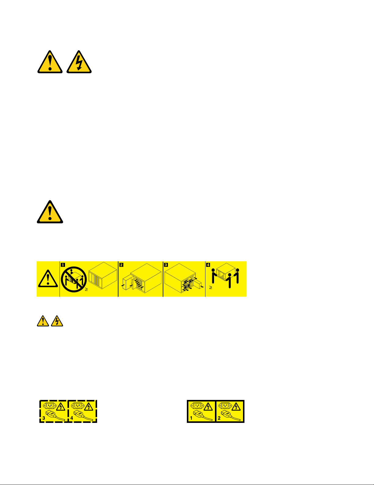
Statement 4
Three graphic illustrations for safety practices when lifting.
viii
Lenovo Storage D1212/D1224/D3284Hardware Installation and Maintenance Guide
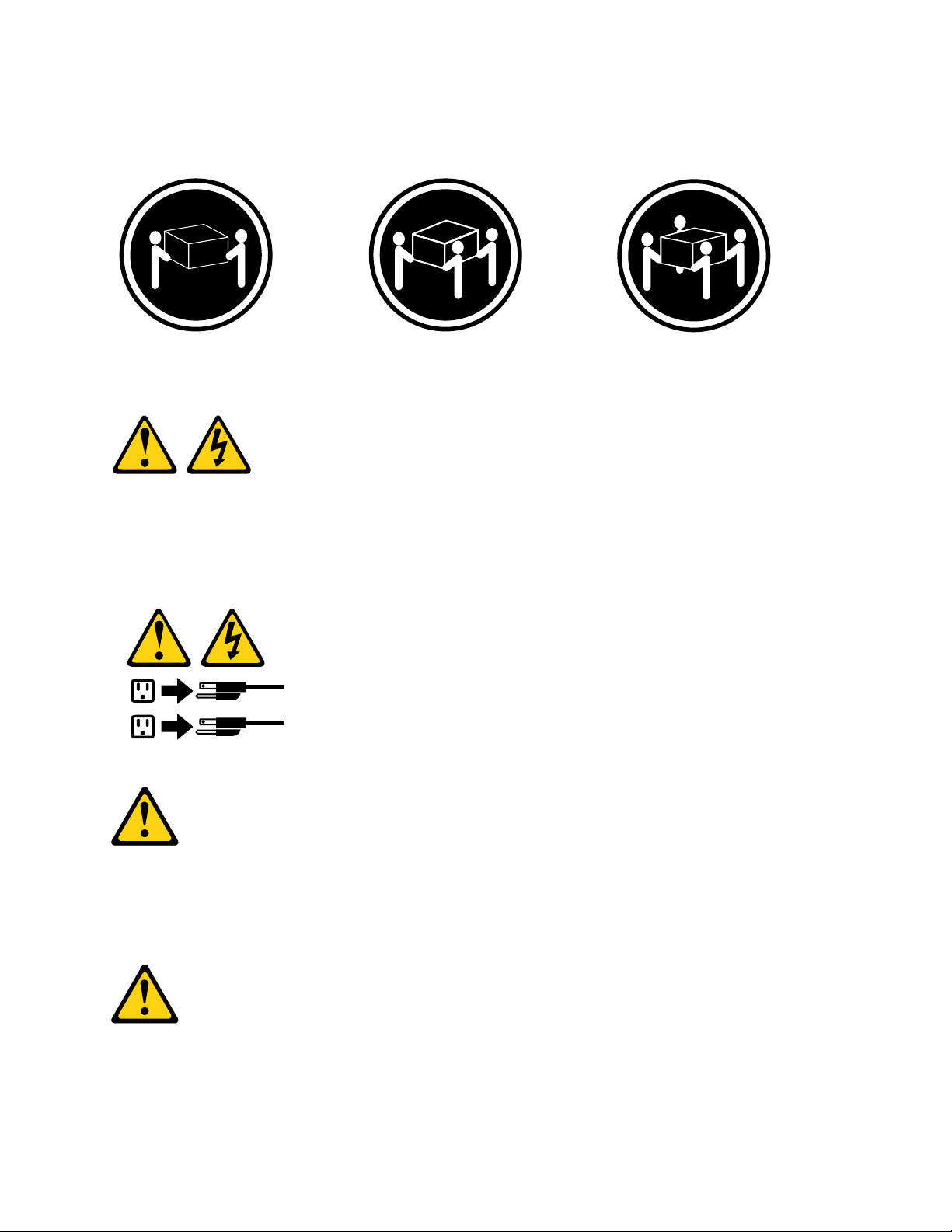
CAUTION: Use safe practices when lifting.
1
2
≥ 18 kg (39.7 lb) ≥ 32 kg (70.5 lb) ≥ 55 kg (121.2 lb)
Statement 5
CAUTION:
The power control button on the device and the power switch on the power supply do not turn off the
electrical current supplied to the device. The device also might have more than one power cord. To
remove all electrical current from the device, ensure that all power cords are disconnected from the
power source.
Statement 6
CAUTION:
If you install a strain-relief bracket option over the end of the power cord that is connected to the
device, you must connect the other end of the power cord to an easily accessible power source.
Statement 7
CAUTION:
If the device has doors, be sure to remove or secure the doors before moving or lifting the device to
avoid personal injury. The doors will not support the weight of the device.
© Copyright Lenovo 2016, 2018 ix
Statement 8
CAUTION:
Never remove the cover on a power supply or any part that has the following label attached.
Hazardous voltage, current, and energy levels are present inside any component that has this label
attached. There are no serviceable parts inside these components. If you suspect a problem with one
of these parts, contact a service technician.
Statement 9
CAUTION:
To avoid personal injury, disconnect the hot-swap fan cables before removing the fan from the device.
Statement 10
CAUTION:
Do not place any object weighing more than 82 kg (180 lb) on top of rack-mounted devices.
>82 kg (180 lb)
Statement 11
CAUTION:
The following label indicates sharp edges, corners, or joints nearby.
x
Lenovo Storage D1212/D1224/D3284Hardware Installation and Maintenance Guide
Statement 12
CAUTION:
The following label indicates a hot surface nearby.
Statement 13
DANGER
Overloading a branch circuit is potentially a fire hazard and a shock hazard under certain
conditions. To avoid these hazards, ensure that your system electrical requirements do not exceed
branch circuit protection requirements. Refer to the information that is provided with your device
for electrical specifications.
Statement 14
CAUTION:
Hazardous voltage, current, and energy levels might be present. Only a qualified service technician is
authorized to remove the covers where the following label is attached.
Statement 15
CAUTION:
Make sure that the rack is secured properly to avoid tipping when the server unit is extended.
© Copyright Lenovo 2016, 2018 xi
Statement 16
CAUTION:
Some accessory or option board outputs exceed Class 2 or limited power source limits and must be
installed with appropriate interconnecting cabling in accordance with the national electric code.
Statement 17
CAUTION:
The following label indicates moving parts nearby.
Statement 18
CAUTION:
To reduce the risk of electric shock or energy hazards:
• This equipment must be installed by trained service personnel in a restricted-access location, as
defined by the NEC and IEC 60950, Third Edition, The Standard for Safety of Information
Technology Equipment.
• Connect the equipment to a reliably grounded safety extra low voltage (SELV) source. An SELV
source is a secondary circuit that is designed so that normal and single fault conditions do not
cause the voltages to exceed a safe level (60 V direct current).
• The branch circuit overcurrent protection must be rated at a minimum of 5 A to a maximum of 15 A.
• Use 14 American Wire Gauge (AWG) or 2.5 mm
2
copper conductor only, not exceeding 3 meters in
length.
• Torque the wiring-terminal screws to 12 inch-pounds (1.4 newton-meters).
• Incorporate a readily available approved and rated disconnect device in the field wiring.
Statement 19
CAUTION:
The power-control button on the device does not turn off the electrical current supplied to the device.
The device also might have more than one connection to dc power. To remove all electrical current
xii
Lenovo Storage D1212/D1224/D3284Hardware Installation and Maintenance Guide
from the device, ensure that all connections to dc power are disconnected at the dc power input
terminals.
Statement 20
CAUTION:
To avoid personal injury, before lifting the unit, remove all the blades to reduce the weight.
Statement 21
CAUTION:
Hazardous energy is present when the blade is connected to the power source. Always replace the
blade cover before installing the blade.
Statement 22
CAUTION:
To reduce the risk of electric shock or energy hazards:
• This equipment must be installed by trained service personnel in a restricted-access location, as
defined by the NEC and IEC 60950, Third Edition, The Standard for Safety of Information
Technology Equipment.
• Connect the equipment to a reliably grounded safety extra low voltage (SELV) source. An SELV
source is a secondary circuit that is designed so that normal and single fault conditions do not
cause the voltages to exceed a safe level (60 V direct current).
• The branch circuit overcurrent protection must be rated at a minimum of 13 A to a maximum of 15
A.
• Use 16 American Wire Gauge (AWG) or 1.3 mm
2
copper conductor only, not exceeding 3 meters in
length.
• Torque the wiring-terminal screws to 12 inch-pounds (1.4 newton-meters).
• Incorporate a readily available approved and rated disconnect device in the field wiring.
Statement 23
© Copyright Lenovo 2016, 2018 xiii
CAUTION:
Do not place any object weighing more than 50 kg (110 lb) on top of rack-mounted devices.
>50 kg (110 lb)
Statement 24
CAUTION:
To reduce the risk of electric shock or energy hazards:
• This equipment must be installed by trained service personnel in a restricted-access location, as
defined by the NEC and IEC 60950, Third Edition, The Standard for Safety of Information
Technology Equipment.
• Connect the equipment to a reliably grounded safety extra low voltage (SELV) source. An SELV
source is a secondary circuit that is designed so that normal and single fault conditions do not
cause the voltages to exceed a safe level (60 V direct current).
• The branch circuit overcurrent protection must be rated at a minimum of 12 A to a maximum of 15
A.
• Use 14 American Wire Gauge (AWG) or 2.5 mm
2
copper conductor only, not exceeding 3 meters in
length.
• Torque the wiring-terminal screws to 12 inch-pounds (1.4 newton-meters).
• Incorporate a readily available approved and rated disconnect device in the field wiring.
Statement 25
CAUTION:
This product contains a Class 1M laser. Do not view directly with optical instruments.
Statement 26
CAUTION:
Do not place any object on top of rack-mounted devices.
xiv
Lenovo Storage D1212/D1224/D3284Hardware Installation and Maintenance Guide
Statement 27
CAUTION:
Hazardous moving parts are nearby.
Statement 28
CAUTION:
The battery is a lithium ion battery. To avoid possible explosion, do not burn the battery. Exchange it
only with an approved part. Recycle or discard the battery as instructed by local regulations.
Statement 29
CAUTION:
This equipment is designed to permit the connection of the earthed conductor of the dc supply circuit
to the earthing conductor at the equipment. If this connection is made, all of the following conditions
must be met:
• This equipment shall be connected directly to the dc supply system earthing electrode conductor
or to a bonding jumper from an earthing terminal bar or bus to which the dc supply system earthing
electrode conductor is connected.
• This equipment shall be located in the same immediate area (such as, adjacent cabinets) as any
other equipment that has a connection between the earthed conductor of the same dc supply
circuit and the earthing conductor, and also the point of earthing of the dc system. The dc system
shall not be earthed elsewhere.
• The dc supply source shall be located within the same premises as this equipment.
• Switching or disconnecting devices shall not be in the earthed circuit conductor between the dc
source and the point of connection of the earthing electrode conductor.
© Copyright Lenovo 2016, 2018 xv
Statement 30
108kg
(237 lbs)
(2X)
(6X)
(4X)
(4X)
43.2 kg
(95 lbs)
CAUTION:
To reduce the risk of electric shock or energy hazards:
• This equipment must be installed by trained service personnel in a restricted-access location, as
defined by the NEC and IEC 60950-1, First Edition, The Standard for Safety of Information
Technology Equipment.
• Connect the equipment to a reliably grounded safety extra low voltage (SELV) source. An SELV
source is a secondary circuit that is designed so that normal and single fault conditions do not
cause the voltages to exceed a safe level (60 V direct current).
• The branch circuit overcurrent protection must be rated 20 A.
• Use 12 American Wire Gauge (AWG) or 2.5 mm
2
copper conductor only, not exceeding 4.5 meters in
length.
• Incorporate a readily available approved and rated disconnect device in the field wiring.
Statement 32
CAUTION:
To avoid personal injury, before lifting the unit, remove all the blades, power supplies, and removable
modules to reduce the weight.
Statement 33
Statement 33 illustrations and caution statement for disconnecting all power cords.
CAUTION: This device does not provide a power control button. Removing power supply modules or turning off
the server blades does not turn off the electrical current supplied to the device. The device also might have
more than one power cord. To remove all electrical current from the device, ensure that all power cords are
disconnected from the power source.
xvi Lenovo Storage D1212/D1224/D3284Hardware Installation and Maintenance Guide
Statement 37
DANGER
When you populate a rack cabinet, adhere to the following guidelines:
• Always lower the leveling pads on the rack cabinet.
• Always install the stabilizer brackets on the rack cabinet.
• Always install the heaviest devices in the bottom of the rack cabinet.
• Do not extend multiple devices from the rack cabinet simultaneously, unless the rack-mounting
instructions direct you to do so. Multiple devices extended into the service position can cause
your rack cabinet to tip.
• If you are not using the IBM 9308 rack cabinet, securely anchor the rack cabinet to ensure its
stability.
Rack Safety Information, Statement 2
DANGER
• Always lower the leveling pads on the rack cabinet.
• Always install stabilizer brackets on the rack cabinet.
• Always install servers and optional devices starting from the bottom of the rack cabinet.
• Always install the heaviest devices in the bottom of the rack cabinet.
UL regulatory information
This device is for use only with Listed CONREF_to_boilerplate_terms.
Attention: This product is suitable for use on an IT power distribution system whose maximum phase-to
phase-voltage is 240 V under any distribution fault condition.
© Copyright Lenovo 2016, 2018 xvii

xviii Lenovo Storage D1212/D1224/D3284Hardware Installation and Maintenance Guide
Chapter 1. Safety Guidelines
This chapter contains following items:
• “Safe Handling” on page 1
• “Operation” on page 1
• “Electrical Safety” on page 3
• “Rack System Safety Precautions” on page 4
Safe Handling
CAUTION:
Use this equipment in a manner specified by the manufacturer: failure to do this may cancel the
protection provided by the equipment.
• Permanently unplug the enclosure before you move it or if you think that it has become damaged in
any way.
• A safe lifting height is 20U.
• Always remove the Power Cooling Modules (PCMs) to minimize weight before you move the
enclosure.
• Do not lift the enclosure by the handles on the PCMs – they are not designed to take the weight.
• For 5U enclosures, it is recommended that a minimum of three people lift the enclosure using the
lifting straps supplied with the enclosure. Remove all DDIC modules from both drawers and make
sure the drawers are closed firmly and locked shut.
Fully configured 2U12 enclosures can weigh up to 28 kg (62 lb).
Fully configured 2U24 enclosures can weigh up to 25 kg (55 lb).
Do not try to lift the enclosure by yourself.
Operation
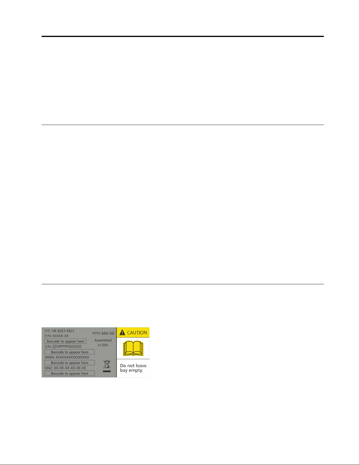
Important: Operation of the enclosure with ANY drive carrier modules missing disrupts the airflow and the
drives could not receive sufficient cooling. It is ESSENTIAL that all apertures hold drives before the enclosure
system is used. Empty drive bays must hold dummy drive carrier modules.
Figure 1. Module Bay Caution Label (1)
© Copyright Lenovo 2016, 2018 1
2U Enclosures Only
• Replace a defective PCM with a fully operational PCM within 24 hours. Refer to “Environment” on page
113. Do not remove a defective PCM unless you have a replacement model of the correct type ready for
insertion.
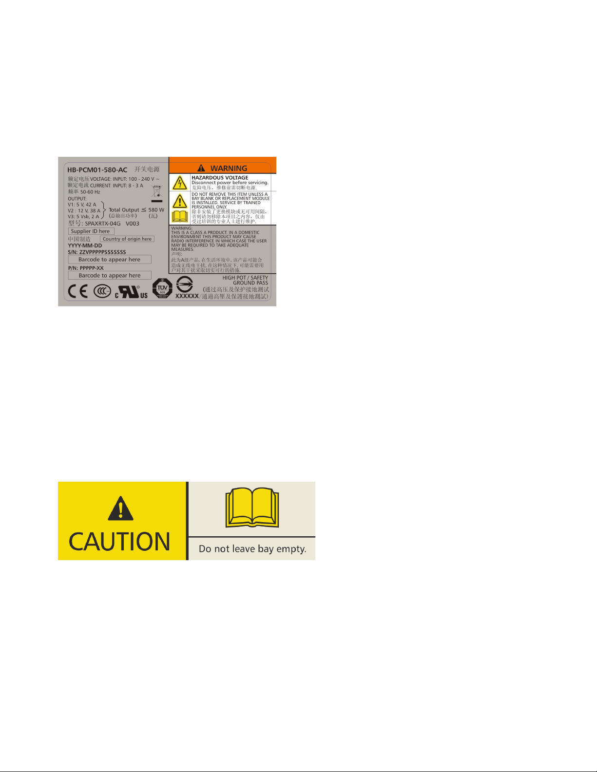
• Before removal/replacement of a PCM disconnect supply power from the PCM to be replaced. Refer to
“Replacing a Cooling Module” on page 89
Figure 2. PCM Warning Label
5U Enclosures Only
CAUTION:
To prevent overturning, drawer interlocks stop users from opening both drawers at the same time. Do
not attempt to force open a drawer when the other drawer in the enclosure is already open. In a rack
containing more than one enclosure, do not open more than one drawer per rack at a time.
Important: All rear modules are part of the fire enclosure and must only be removed when a replacement
can be immediately inserted.
Important: The enclosure could not receive sufficient airflow or cooling if it is operated with any of the rear
modules missing. It is essential that every module bay is filled either with a module or a blank module.
Figure 3. Module Bay Caution Label (2)
Replace any defective module with a fully operational unit as soon as possible. Do not remove cooling
modules, PSUs, or ESMs unless you have a replacement model of the correct type ready for insertion.
CAUTION:
To prevent overturning, drawer interlocks stop users from opening both drawers at the same time. Do
not attempt to force open a drawer when the other drawer in the enclosure is already open. In a rack
containing more than one enclosure, do not open more than one drawer per rack at a time.
CAUTION:
2
Lenovo Storage D1212/D1224/D3284Hardware Installation and Maintenance Guide
Operating temperatures inside the enclosure drawers can reach up to 60°C. Take care when opening
drawers and removing drive carriers.
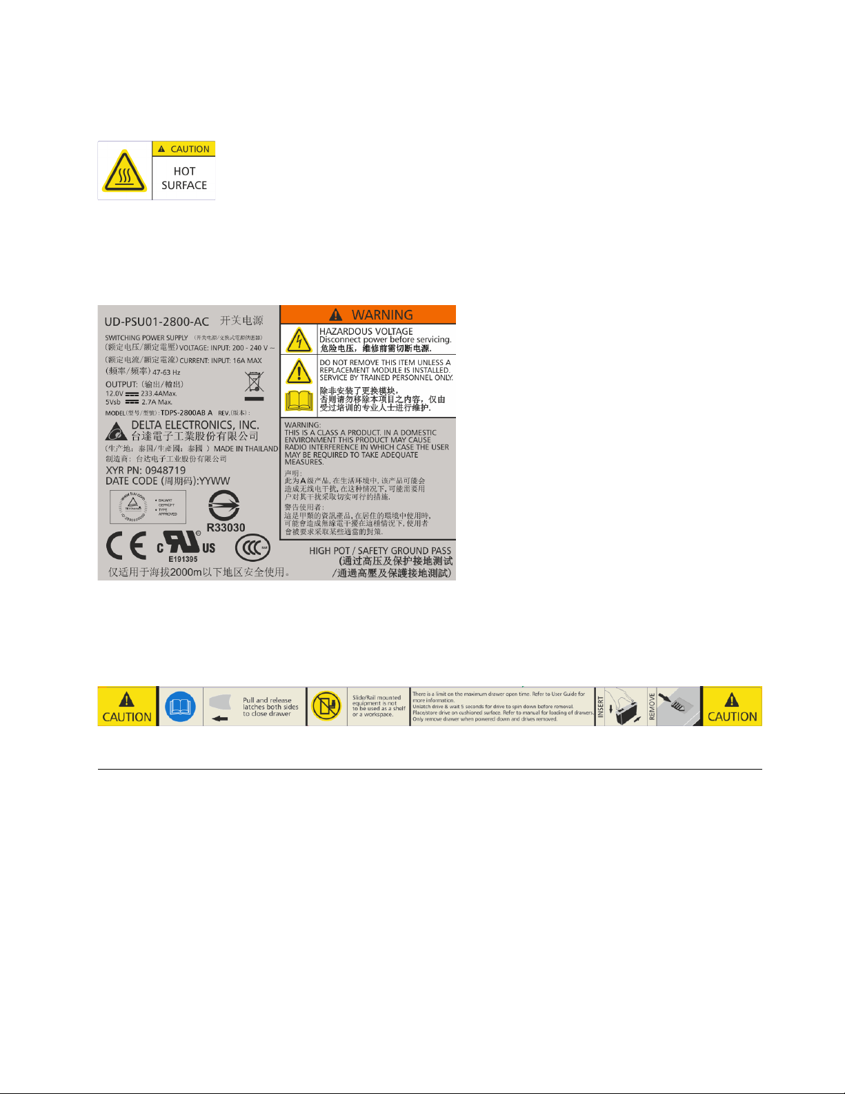
Figure 4. Hot Surface Warning Label
CAUTION:
Due to product acoustics, it is recommended that users wear ear protection for any prolonged
exposure.
Figure 5. PSU Warning Label
Before removing a module, disconnect all power cords and cables.
Open drawers must not be used to support any other equipment.
Figure 6. Drawer Caution Label
Electrical Safety
• The enclosure must only be operated from a power supply input voltage range of 200 VAC to 240 VAC, 50
Hz to 60 Hz.
• Provide a suitable power source with electrical overload protection to meet the requirements in the
technical specification.
• The power supply cord must have a safe electrical earth connection. Check the connection to earth of the
enclosure before you switch on the power supply.
Important: The enclosure must be grounded before applying power.
• The plug on the power supply cord is used as the main disconnect device. Ensure that the socket outlets
are located near the equipment and are easily accessible.
Chapter 1. Safety Guidelines 3
Do not remove covers from the PCM, PSU, or cooling modules– there is a danger of electric shock inside.
Return the PCM, PSU, or cooling modules to your supplier for repair.
Important: The RJ45 socket on the ESM is for Ethernet connection only and must not be connected to a
telecommunications network.
2U Enclosures Only
2U enclosures are intended to operate with two PCMs.
Figure 7. Power Cooling Module Warning Label
When bifurcated power cords ("Y" leads) are used, these cords must only be connected to a supply range of
200-240 VAC.
5U Enclosures Only
5U enclosures are intended to operate with two PSUs and five cooling modules.
When powered by multiple AC sources, disconnect all supply power for complete isolation.
Do not remove covers from the enclosure or any of the modules – there is a danger of electric shock inside.
Do not attempt to disassemble the rear sub-chassis from the enclosure. Return any damaged components to
your supplier for repair.
CAUTION:
The PSUs contain double pole/neutral fusing. Ensure that your electrical installation can support this.
Rack System Safety Precautions
The following safety requirements must be considered when the enclosure is mounted in a rack:
• The rack construction must be capable of supporting the total weight of the installed enclosures. The
design should incorporate stabilizing features suitable to prevent the rack from tipping or being pushed
over during installation or in normal use.
• When loading a rack with enclosures, fill the rack from the bottom up and empty from the top down.
• Do not try to lift the enclosure by yourself.
To avoid danger of the rack falling over, under no circumstances should more than one enclosure be
moved out of the cabinet at any one time.
• The system must be operated with low-pressure rear exhaust installation. (Back pressure created by rack
doors and obstacles not to exceed 5 pascals [0.5 mm water gauge]).
• The rack design should consider the maximum operating ambient temperature for the enclosure, which is
40°C for 2U enclosures and 5U enclosures.
• The rack should have a safe electrical distribution system. It must provide overcurrent protection for the
enclosure and must not be overloaded by the total number of enclosures installed in the rack. When
addressing these concerns consideration should be given to the electrical power consumption rating
shown on the nameplate.
4
Lenovo Storage D1212/D1224/D3284Hardware Installation and Maintenance Guide

• The electrical distribution system must provide a reliable earth connection for each enclosure and the
rack.
• The rack, when configured with the enclosures, must meet the safety requirements of UL 60950-1 and IEC
60950-1.
2U Enclosures Only
Always remove all PCMs to minimize weight, before loading the enclosure into a rack.
Each PCM in each enclosure has an earth leakage current of 1.0 mA. The design of the electrical distribution
system must consider the total earth leakage current from all the PCMs in all the enclosures. The rack
requires labeling with “HIGH LEAKAGE CURRENT. Earth connection essential before connecting supply”.
5U Enclosures Only
The enclosure must only be mounted into a rack using the supplied rail kit. Due to its weight and length, the
enclosure must not be flange mounted.
Before mounting the enclosure, remove all DDIC modules from both drawers and make sure that the drawers
are closed firmly and locked shut. Do not try to lift the enclosure by yourself (see “Safe Handling” on page 1).
The minimum open area for the rack doors is 70%.
Each PSU in each enclosure has a ground leakage current of 1.6 mA. The design of the electrical distribution
system must consider the total ground leakage current from all the PSUs in all the enclosures. The rack must
be labeled with the words: "HIGH LEAKAGE CURRENT. Ground connection essential before connecting
supply."
Chapter 1. Safety Guidelines 5

6 Lenovo Storage D1212/D1224/D3284Hardware Installation and Maintenance Guide

Chapter 2. System Overview
This chapter contains the following items:
• “Enclosure Configurations” on page 7
• “Enclosure Variants” on page 11
• “The 2U Enclosure Core Product” on page 12
• “The 5U Enclosure Core Product” on page 14
• “Operator’s (Ops) Panel (2U Enclosures)” on page 17
• “Operator’s (Ops) Panel (5U Enclosures)” on page 19
• “Disk Drive LEDs” on page 20
• “Power Cooling Modules (PCM)” on page 21
• “Power Supply Unit (PSU)” on page 22
• “Cooling Module” on page 23
• “Environmental Service Module (ESM) ” on page 24
• “Drive Carrier Module (2U Enclosures)” on page 27
• “Enclosure Management” on page 31
Enclosure Introduction
You can connect Storage D1212/D1224/D3284 enclosures directly to the host. You also can optionally
connect Storage D3284 enclosure to a Lenovo Storage DS-series as the expansion enclosure. For more
information about the operation of Storage DS-series, refer to ThinkSystem DS6200/DS4200/DS2200/DS
EXP Storage Manager Guide.
Enclosure Configurations
The storage system is available in three enclosure configurations:
• 2U (rack space) disk drive enclosure (see Figure 8 “2U12 Enclosure System – front view ” on page 8 and
Figure 9 “2U12 Enclosure System – rear view ” on page 8): holds up to 12 low profile (1 inch high), 3.5 inch
form factor drives in a horizontal orientation.
• 2U (rack space) disk drive enclosure (see Figure 10 “2U24 Enclosure System – front view ” on page 9 and
Figure 11 “2U24 Enclosure System – rear view ” on page 9): holds up to 24 low profile (5/8 inch high), 2.5
inch form factor drives in a vertical orientation.
• 5U (rack space) disk drive enclosure (see Figure 12 “5U84 Enclosure System – front view ” on page 10 and
Figure 13 “5U84 Enclosure System – rear view ” on page 11) contains two drawers of 42 drives each (84
drives in total). 2.5" drives require 3.5" adapters.
The following product information is displayed on the HBA/ RAID adapter:
• Product ID "2U12ENC" for D1212, "2U24ENC" for D1224, "5U84ENC or D3284" for D3284 is displayed
on the host RAID adapter
Each individual drive assembly is hot pluggable and replaceable on site.
© Copyright Lenovo 2016, 2018 7
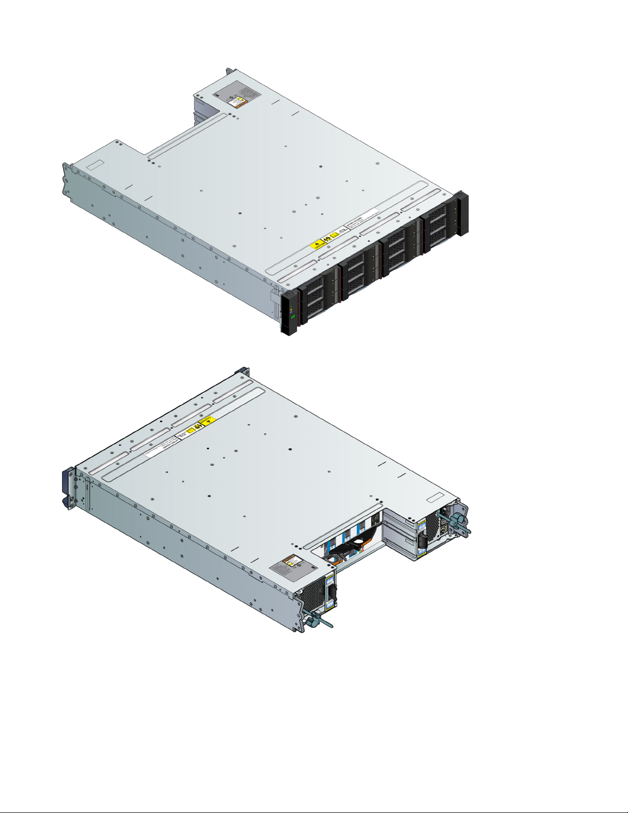
Figure 8. 2U12 Enclosure System – front view
Figure 9. 2U12 Enclosure System – rear view
8 Lenovo Storage D1212/D1224/D3284Hardware Installation and Maintenance Guide
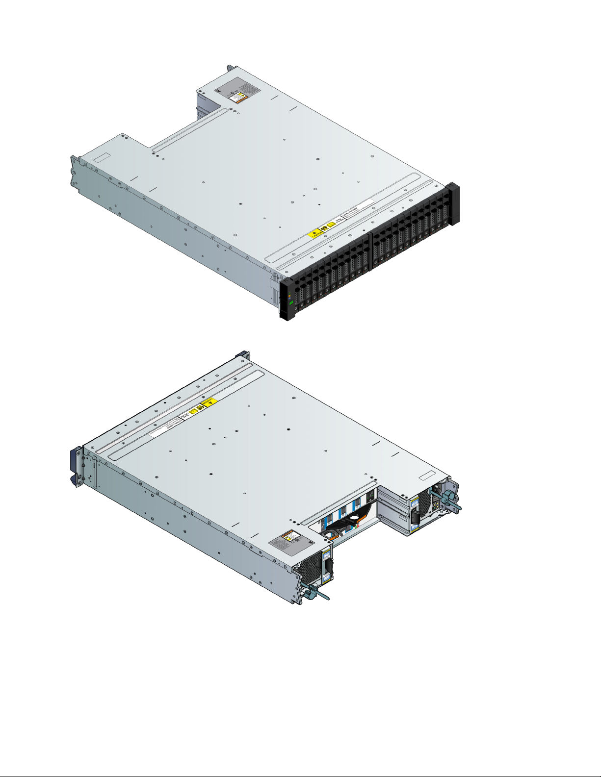
Figure 10. 2U24 Enclosure System – front view
Figure 11. 2U24 Enclosure System – rear view
Chapter 2. System Overview 9
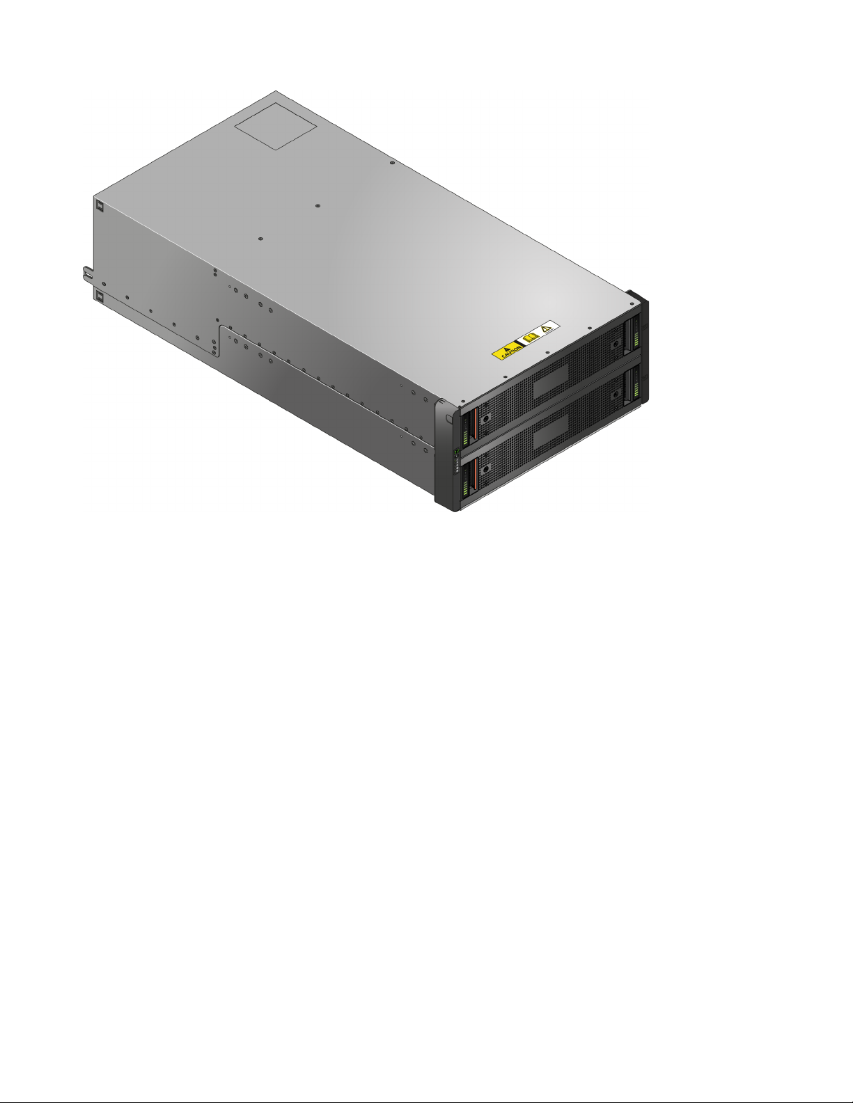
Figure 12. 5U84 Enclosure System – front view
10 Lenovo Storage D1212/D1224/D3284Hardware Installation and Maintenance Guide
 Loading...