

Lenovo SPECTRUM Series Service Manual

SERVICE MANUAL
SPECTRUM Series
http://www.wjel.net
LCD Monitor

THESE DOCUMENTS ARE FOR REPAIR SERVICE INFORMATION ONLY. EVERY
REASONABLE EFFORT HAS BEEN MADE TO ENSURE THE ACCURACY OF THIS MANUAL;
WE CANNOT GUARANTEE THE ACCURACY OF THIS INFORMATION AFTER THE DATE
OF PUBLICATION AND DISCLAIMS RE LIABILITY FOR CHANGES, ERRORS OR
OMISSIONS,
MANUFACTURE DATA : May-25. 2004
http://www.wjel.net
1

TABLE OF CONTENTS
PAGE
1. SPECIFICATIONS .................................................................................................... 3
1-1 GENERAL SPECIFICATIONS ...................................................….............. 3
1-2 LCD MONITOR DESCRIPTION .................................................................. 4
1-3 INTERFACE CONNECTOR .................................................................……. 4
2. PRECAUTION AND NOTICES ................................................................................ 5
2-1 ASSEMBLY PRECAUTION ......................................................................... 5
2-2 OPERATIONG PRECAUTION ..................................................................... 5
2-3 STORAGE PRECAUTION …........................................................................ 5
2-4 HIGH VOLTAGE WARNING ....................................................................... 5
3. OPERATING INSTRUCTIONS ................................................................................ 6
4. ADJUSTMENT ..........................................................................................................
5. CIRCUIT & SOFTWARE DESCRIPTION ................................................................
6. TROUBLE SHOOTING.............................................................................................
7. MECHANICAL OF CABINET FRONT DIS-ASSEMBLY........................................... 23
8. PARTS LISTING .........................................................................................………...
9. SCHEMATIC DIAGRAM …..................................................................................... 33~37
10 PCB LAYOUT .....................................................................………………………...
7~8
8~13
14~22
24~33
38~40
http://www.wjel.net
2

1. SPECIFICATIONS FOR LCD MONITOR
1-1 General specifications
1. LCD-PANEL :
Active display area 15 inches or 15.1 inches diagonal
Pixel pitch 0.297 mm x 0.297 mm
Pixel format 1024 x 768 RGB vertical stripe arrangement
2. Display Color :
6-bit, 262144 colors or 8-bit, 16.7 million colors
3. ●External Controls :
a).Power On/Off, Auto key, Rotary-knob ( for shuttle)
b).Power On/Off, Auto key, Left key, Right key ( for 4-key )
●OSD menu Controls
Contrast, Brightness, Focus, Clock,H-position, V-position, Language, Recall-C2(warm
color), Recall-C1 (Cool color), Reset, Exit-OSD, Red, Green, Blue
4. Input Video Signal :
Analog-signal 0.7Vpp
Video signal termination impedance 75 OHM
5. Scanning Frequencies :
Horizontal: 29 KHz - 63 KHz
Vertical: 55 Hz – 75 Hz
Pixel clock: 80 MHz
6. Factory Preset Timing : 18
User Timings : 19
Input signal tolerance : H tolerance ±1 K, V tolerance ±1 Hz
7. Power Source :
Switching Mode Power Supply
AC 100 – 240 V, 50/60 Hz Universal Type
8. Operating Temperature : 5℃ - 35℃ Ambient
Non-operating Temperature : -20℃ - 60℃
9. Humidity :
Operating : 20% to 80% RH (non-condensing)
Non Operating : 5% to 95%RH (38.7℃ maximum wet bulb temperature)
10. Weight : 3.0 kg
11. External Connection : 15Pin D-type Connector, AC power-Cord
12. View Angle : x-axis right/left = 60, y-axis up/down = 45 ,45
13. Outside dimension : Width x Height x Thickness = 356mm x 358mm x 160mm
14. Plug and Play : VESA DDC1/DDC2B
15. Power saving : VESA DPMS
http://www.wjel.net
3
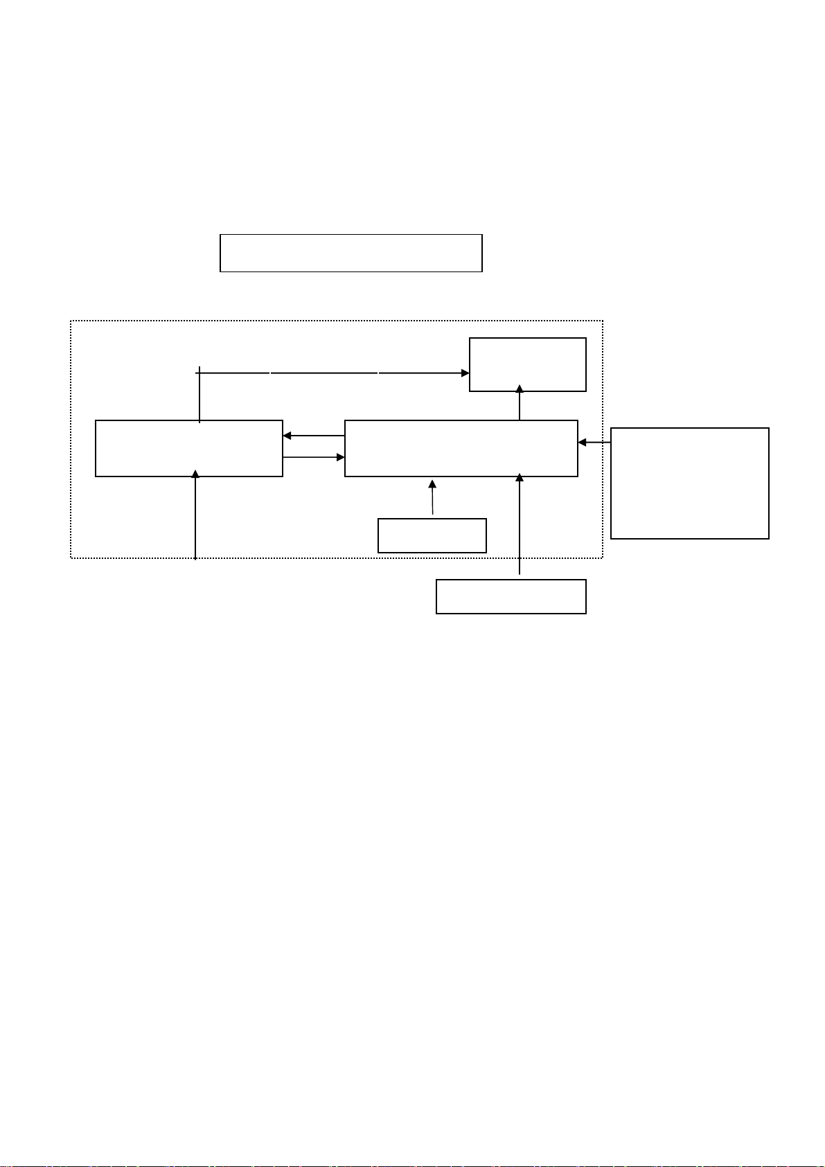
1-2 LCD MONITOR DESCRIPTION
The LCD MONITOR will contain an main board, an inverter/power board, keypad board
and internal adapter which house the flat panel control logic, brightness control logic and
DDC.
The power board will provide AC to DC Inverter voltage to drive the backlight of panel
and the main board chips each voltage.
1-3 Interface Connectors
(A) AC-Power Cable
(B) Video Signal Connectors and Cable
(C) Audio Cable
Power board
(include: adapter, inverter)
AC-IN
100V-240V
Monitor Block Diagram
CCFL Drive.
Main Board
Keyboard
Flat Panel and
CCFL backlight
HOST Computer
RS232 Connector
For white balance
adjustment in factory
mode
Video signal, DDC
http://www.wjel.net
4

2. PRECAUTIONS AND NOTICES
2-1 ASSEMBLY PRECAUTION
(1) Please do not press or scratch LCD panel surface with anything hard. And do not soil
LCD panel surface by touching with bare hands (Polarizer film, surface of LCD panel is
easy to be flawed)
In the LCD panel, the gap between two glass plates is kept perfectly even to maintain
display characteristic and reliability. If this panel is subject to hard pressing, the
following occurs :
(a) Uniform color (b) Orientation of liquid crystal becomes disorder
(2) Please wipe out LCD panel surface with absorbent cotton or soft cloth in case of it
being soiled.
(3) Please wipe out drops of adhesive like saliva and water in LCD panel surface
immediately.
They might damage to cause panel surface variation and color change.
(4) Do not apply any strong mechanical shock to the LCD panel.
2-2 OPERATING PRECAUTIONS
(1) Please be sure to unplug the power cord before remove the back-cover. (be sure the
power is turn-off)
(2) Please do not change variable resistance settings in MAIN-BOARD, they are adjusted
to the most suitable value. If they are changed, it might happen LUMINANCE does not
satisfy the white balance spec.
(3) Please consider that LCD backlight takes longer time to become stable of radiation
characteristic in low temperature than in room temperature.
(4) Please pay attention to displaying the same pattern for very long-time. Image might
stick on LCD.
2-3 STORAGE PRECAUTIONS
(1) When you store LCD for a long time, it is recommended to keep the temperature
between 5℃-35 without the exposure of sunlight and to keep the humidity less than ℃
80% RH.
(2) Please do not leave the LCD in the environment of high humidity and high temperature
such as 60℃ 90%RH.
(3) Please do not leave the LCD in the environment of low temperature; below -15℃.
2-4 HIGH VOLTAGE WARNING
The high voltage was only generated by INVERTER module, if carelessly contacted the
transformer on this module, can cause a serious shock. (the lamp voltage after stable
around 600V, with lamp current around 8mA, and the lamp starting voltage was around
1500V, at Ta=25℃)
http://www.wjel.net
5
3. OPERATING INSTRUCTIONS
This procedure gives you instructions for installing and using the LM520 LCD monitor
display.
1. Position the display on the desired operation and plug–in the power cord into External
Adapter AC outlet. Three-wire power cord must be shielded and is provided as a safety
precaution as it connects the chassis and cabinet to the electrical conduct ground. If
the AC outlet in your location does not have provisions for the grounded type plug, the
installer should attach the proper adapter to ensure a safe ground potential.
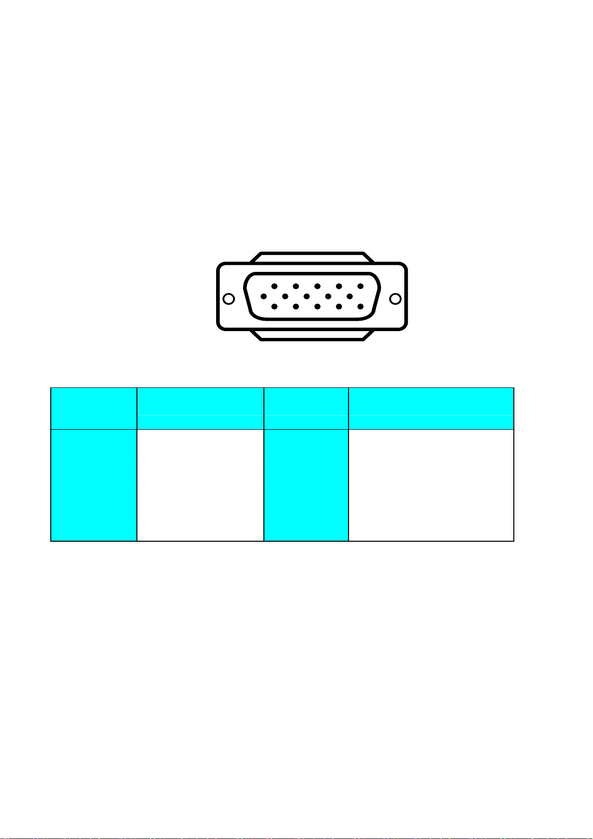
2. Connect the 15-pin color display shielded signal cable to your signal system device
and lock both screws on the connector to ensure firm grounding. The connector
information is as follow:
PIN NO.
15 - Pin Color Display Signal Cable
DESCRIPTION
1
6
11 15
PIN NO.
5
10
DESCRIPTION
1. RED 9. 5V power from VGA-card
2. GREEN 10. GND
3. BLUE 11. SYNC. GND
4. GND 12. SDA
5. GND 13. HORIZ. SYNC
6. GND-R 14. VERT. SYNC
7. GND-G 15. SCL
8. GND-B
3. Apply power to the display by turning the power switch to the "ON" position and allow
about thirty seconds for Panel warm-up. The Power-On indicator lights when the
display is on.
4. With proper signals feed to the display, a pattern or data should appear on the screen,
adjust the brightness and contrast to the most pleasing display, or press auto-key to
http://www.wjel.net
get the best picture-quality.
5. This monitor has power saving function following the VESA DPMS. Be sure to connect
the signal cable to the PC.
6. If your LCD monitor requires service, it must be returned with the power cord &
Adapter.
6
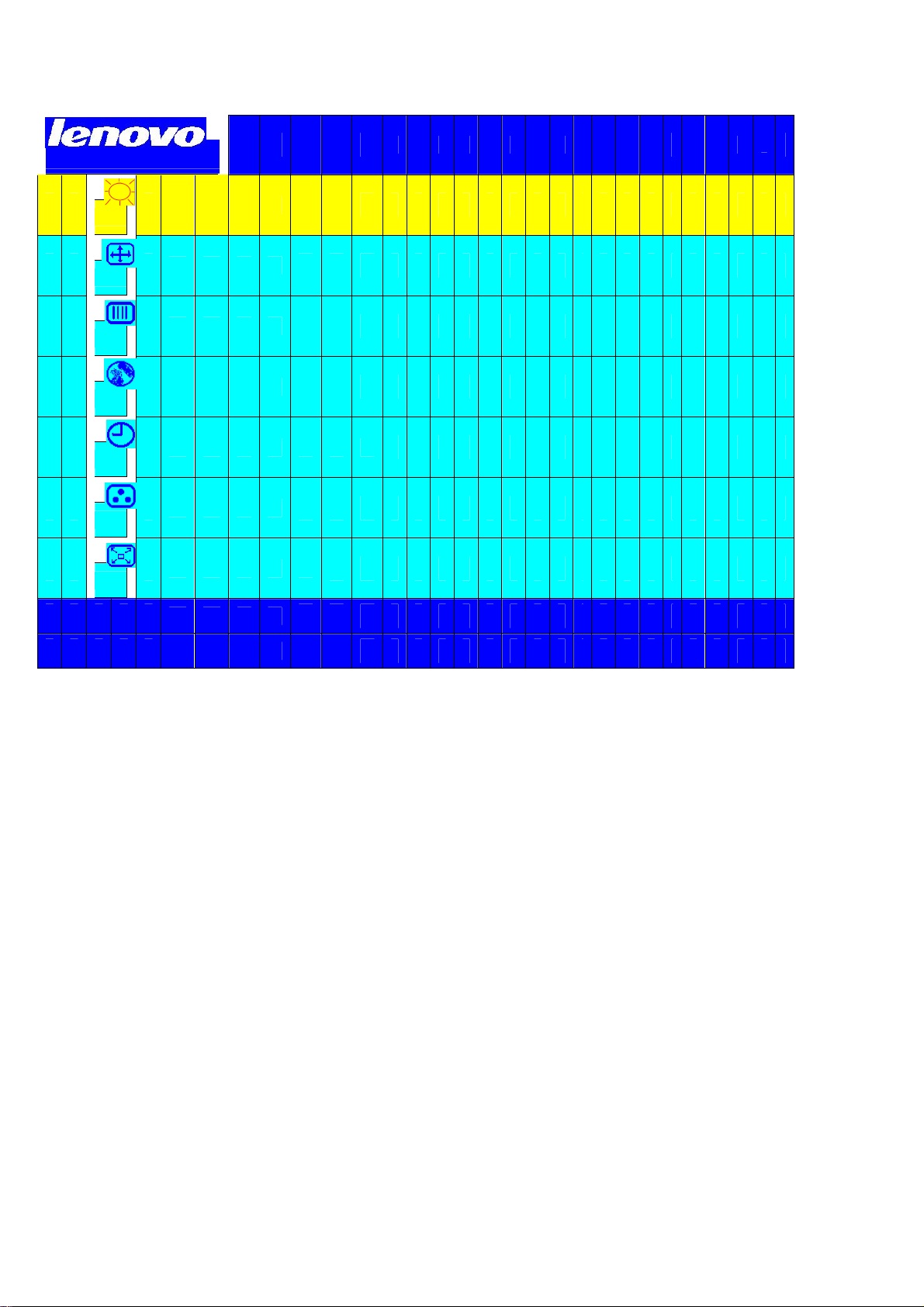
亮 度 和 对 比 度
位 置 调 整
视 频 杂 讯
语 言 选 择
O S D
色 温 调 整
O S D
退 出 菜 单
显 示 时 间
位 置
4. ADJUSTMENT
1 0 2 4 x 7 6 8 4 8 K 5 9 H
z
恢 复 出 厂 模 式
http://www.wjel.net
7
5. CIRCUIT-DESCRIPTION
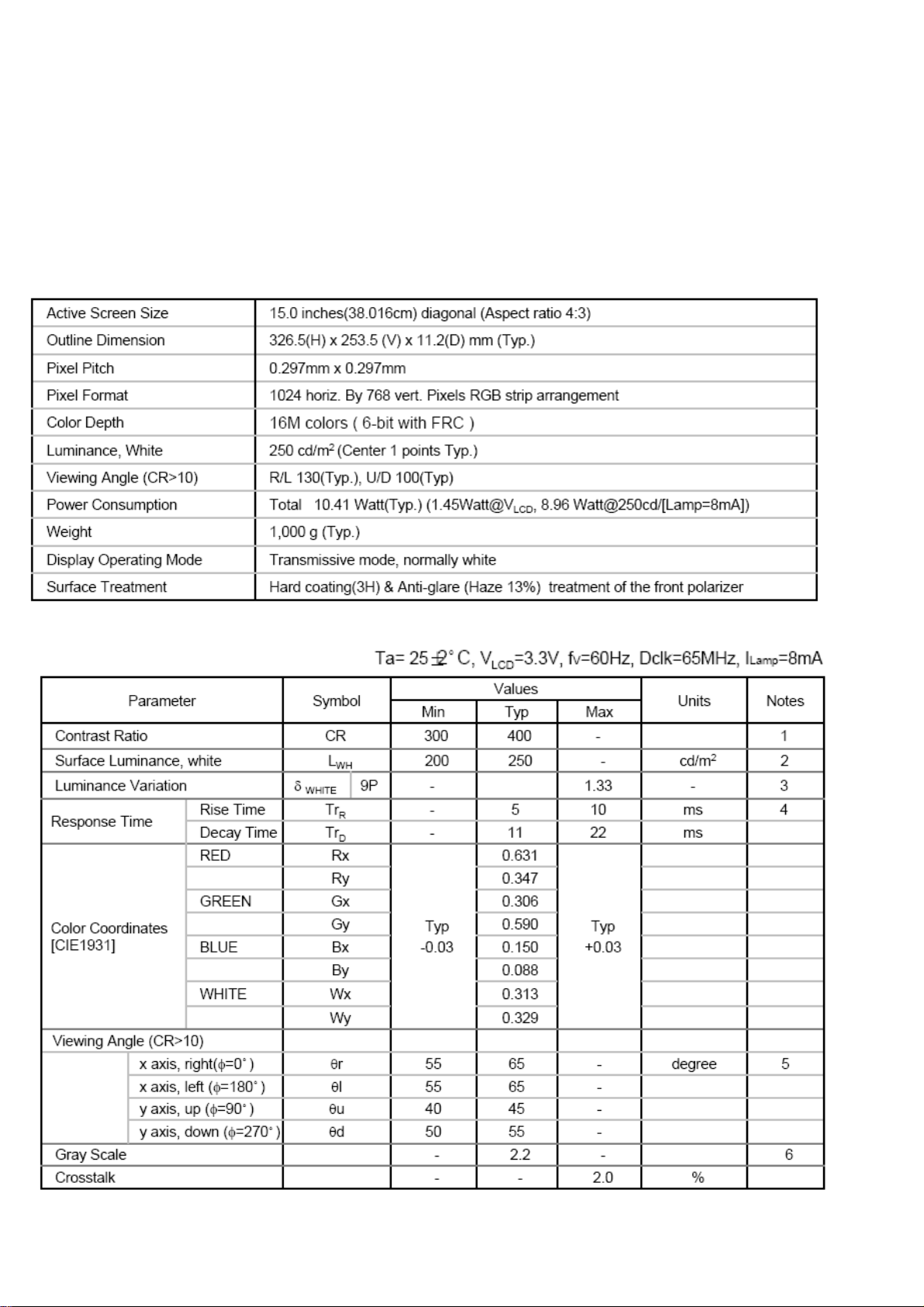
5-1 PANEL SPECIFICATION (LG X08)
5-1-1Panel Feature
- 15” XGA TFT LCD Panel
- 2 CCFLS Backlight System
- Supported (H1024Pixel × V768Lines) resolution
- By applying 8 bit digital data
5-1-2 Display Characteristics
5-1-3 Optical Characteristics
http://www.wjel.net
8
5-1-4 Parameter guide line for CCFL Inverter
INVERTER MAX BRINGTHNESS (Vadj:5.0v), LOAD=120KΩX4
(ROOM TEMPERATURE 25℃ ±4℃)
ITEM SYMBOL MIN. TYP. MAX. UNIT REMARK
Input voltage
Input current Iin 2250 2500 mA FOR 4 LOAD
Output Current Iout 6.0 6.5 7.0 mA FOR 1 LOAD
Frequency
H.V open
H.V Load
Start voltage Vst
Protect delay time PDT
Vin
F 50.0
Vopen
Vload
10.8 12 13.2 V
55.0 60.0 KHZ
1450 1600 1750 Vrms NO LOAD
710 810 910 Vrms RL=120KΩ
1650 1750 1850 Vrms RL=CCFL
0.4 1 4 Sec
FOR 1 LOAD
INVERTER MIN BRINGTHNESS (Vadj:0.0v), LOAD=120KΩX4
(ROOM TEMPERATURE 25℃ ±4℃)
ITEM SYMBOL MIN. TYP. MAX. UNIT REMARK
input voltage
input current Iin 660 750 mA FOR 4 LOAD
Output Current Iout 3.0 3.5 4.0 mA FOR 1 LOAD
Frequency
H.V open
Start voltage Vst
H.V Load
Vin
F 50.0
Vopen
http://www.wjel.net
Vload
10.8 12 13.2 V
55.0 60.0 KHZ
1450 1600 1750 Vrms NO LOAD
1650 1750 1850 Vrms RL=CCFL
350 450 550 Vrms RL=120KΩ
FOR 1 LOAD
9
5-2 SPECIAL FUNCTION with PRESS-KEY
press Menu button during 2 seconds along with plug-in the AC Power cord:
That operation will set the monitor into “Factory- mode”, in Factory mode we can do the
White balance adjustment with RS232 , and view the Backlight counter (this counter is
use to record the panel activate hours ,for convenient the maintainer to check the panel
backlight life time)
In Factory mode, OSD-screen will locate in left top of screen.
Press POWER-button off to on once will quit from factory mode and back to user-mode.
OSD-INDEX EXPLANATION
1. CABLE NOT CONNECTED: Signal-cable not connected.
2. INPUT NOT SUPPORT:
a. INPUT frequency out of range: H > 63kHz, v > 75Hz or H < 28kHz, v < 55Hz
b. INPUT frequency out of VESA-spec. (out of tolerance too far)
3. UNSUPPORT mode, try different Video-card Setting:
Input frequency out of tolerance, but still can catch-up by our system (if this message
show, that means, this is new-user mode, AUTO-CONFIG will disable)
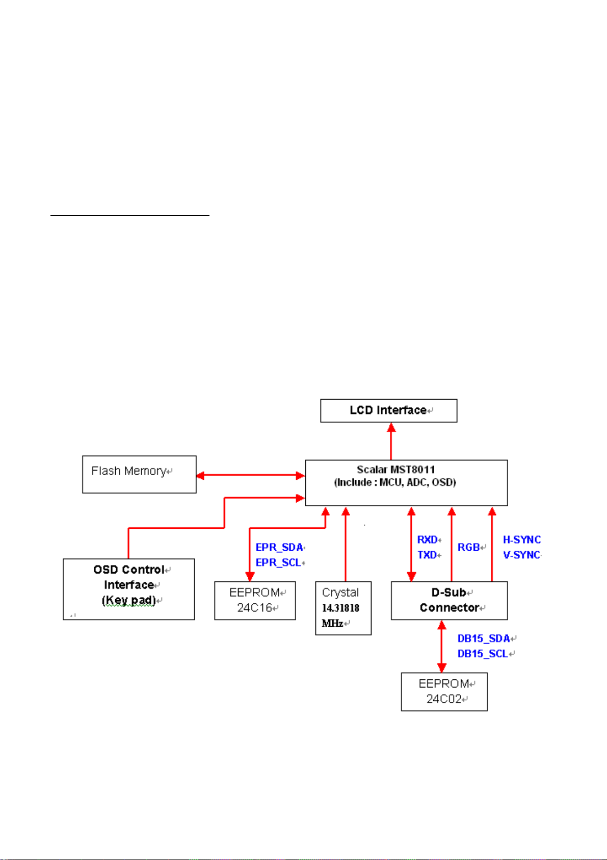
5-3 SIMPLE-INTRODUCTION about LXH-GJ15L4 chipset
http://www.wjel.net
10
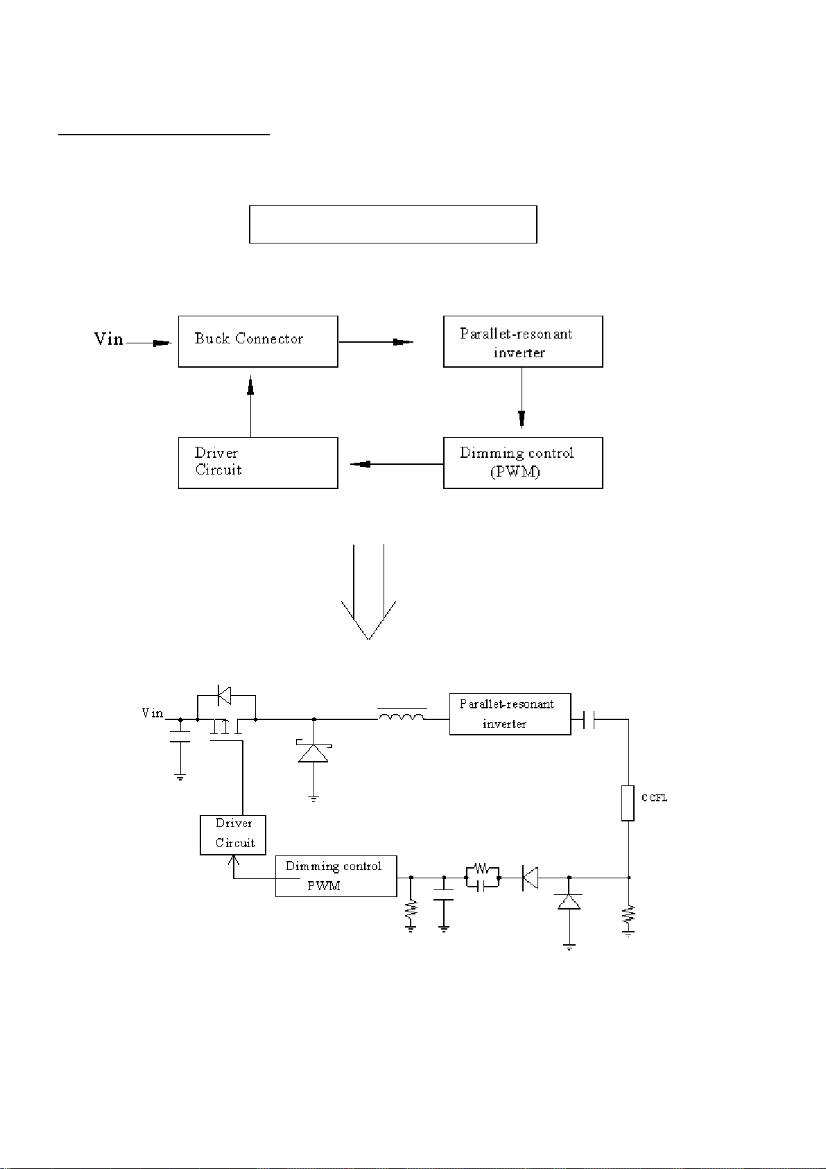
MODULE-TPYE COMPONENT : I
nverter/Power Board
Inverter Block Diagram
http://www.wjel.net
11
1
2
10
12
643
8
9
14
11
13
1516 1
19
18
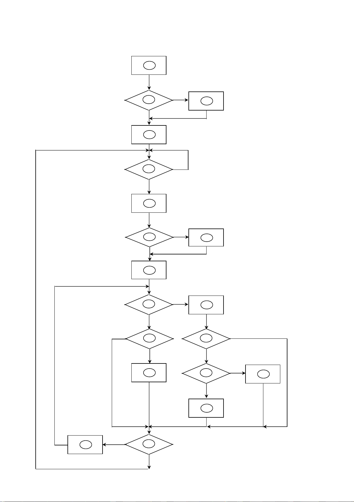
5-4 SOFTWARE FLOW CHART
5
7
http://www.wjel.net
7
12
 Loading...