

Lenovo PC 300GL, PC 300GL 6561 User Manual

Personal Computer
Installing Options in Your Personal Computer
PC 300GL Type 6561


Personal Computer
Installing Options in Your Personal Computer
PC 300GL Type 6561
IBM

Note
Before using this information and the product it supports, be sure to read the general information
under Appendix C, “Notices” on page 82.
Second Edition (January 1998)
The following paragraph does not apply to the United Kingdom or any country where such provisions
are inconsistent with local law: INTERNATIONAL BUSINESS MACHINES CORPORATION PROVIDES
THIS PUBLICATION “AS IS” WITHOUT WARRANTY OF ANY KIND, EITHER EXPRESS OR IMPLIED,
INCLUDING, BUT NOT LIMITED TO, THE IMPLIED WARRANTIES OF MERCHANTABILITY OR
FITNESS FOR A PARTICULAR PURPOSE. Some states do not allow disclaimer of express or implied
warranties in certain transactions, therefore, this statement may not apply to you.
This publication could include technical inaccuracies or typographical errors. Changes are periodically
made to the information herein; these changes will be incorporated in new editions of the publication.
IBM may make improvements and/or changes in the product(s) and/or the program(s) described in this
publication at any time.
This publication was developed for products and services offered in the United States of America. IBM
may not offer the products, services, or features discussed in this document in other countries, and the
information is subject to change without notice. Consult your local IBM representative for information
on the products, services, and features available in your area.
Requests for technical information about IBM products should be made to your IBM reseller or IBM
marketing representative.
Copyright International Business Machines Corporation 1998. All rights reserved.
Note to U.S. Government Users — Documentation related to restricted rights — Use, duplication or
disclosure is subject to restrictions set forth in GSA ADP Schedule Contract with IBM Corp.

Contents
Safety Information . . . . . . . . . . . . . . . . . . . . . . . . . . . . . . . . . . . . . v
Laser Compliance Statement ................................ vi
Lithium Battery Notice .................................. vii
About This Book ..................................... viii
How This Book Is Organized ............................... ix
Related Publications . . . . . . . . . . . . . . . . . . . . . . . . . . . . . . . . . . . . . x
Chapter 1. Overview . . . . . . . . . . . . . . . . . . . . . . . . . . . . . . . . . . . . 1
Available Options and Features .............................. 2
Tools Required . . . . . . . . . . . . . . . . . . . . . . . . . . . . . . . . . . . . . . . . 3
Electrical Safety . . . . . . . . . . . . . . . . . . . . . . . . . . . . . . . . . . . . . . . 4
Handling Static-Sensitive Devices ............................ 5
Chapter 2. Preparing to Install and Remove Options ................ 6
Disconnecting Cables and Removing the Cover .................... 6
Locating Components . . . . . . . . . . . . . . . . . . . . . . . . . . . . . . . . . . . . 8
Internal View . . . . . . . . . . . . . . . . . . . . . . . . . . . . . . . . . . . . . . . 8
Input/Output Connectors . . . . . . . . . . . . . . . . . . . . . . . . . . . . . . . 9
Chapter 3. Working with Options on the System Board .............. 10
Identifying Parts on the System Board .......................... 11
Working with System Memory .............................. 12
Memory Configuration . . . . . . . . . . . . . . . . . . . . . . . . . . . . . . . . . 13
Installing a Memory Module .............................. 14
Removing a Memory Module ............................. 16
Replacing a Microprocessor ................................ 17
Chapter 4. Working with Adapters ........................... 21
Adapters and the Riser Card ............................... 22
Adapter Configuration . . . . . . . . . . . . . . . . . . . . . . . . . . . . . . . . . . . 23
Plug and Play Adapters ................................. 23
Legacy Adapters . . . . . . . . . . . . . . . . . . . . . . . . . . . . . . . . . . . . . 24
Installing Adapters . . . . . . . . . . . . . . . . . . . . . . . . . . . . . . . . . . . . . 25
Routing a Cable from an Adapter to a Drive in Bay 1, 2, or 3 ........... 27
Removing the Side Cover ................................. 28
Replacing the Side Cover ................................. 29
Removing and Replacing the System Board ...................... 30
Removing and Replacing the Fan Assembly ...................... 35
Removing Adapters . . . . . . . . . . . . . . . . . . . . . . . . . . . . . . . . . . . . . 37
Copyright IBM Corp. 1998 iii

Chapter 5. Working with Internal Drives ....................... 39
Drive Specifications . . . . . . . . . . . . . . . . . . . . . . . . . . . . . . . . . . . . . 41
Power and Signal Cables ................................ 42
Accessing Drive Bays .................................... 44
Removing the Metal Shield ............................... 45
Installing a Bay Panel .................................. 47
Working with Drives in Bays 1, 2, and 3 ........................ 48
Rotating the Drive Cage ................................. 48
Installing a Drive in Bay 1, 2, or 3 .......................... 50
Removing a Drive from Bay 1, 2, or 3 ........................ 53
Rotating the Drive Cage Back into Fixed Position ................. 55
Working With Drives in Bay 4 .............................. 56
Removing a Drive from Bay 4 ............................. 56
Installing a Drive in Bay 4 ............................... 58
Chapter 6. Working with Security Options ...................... 60
Installing a U-Bolt ...................................... 61
Erasing Lost or Forgotten Passwords .......................... 64
Chapter 7. Completing the Installation ........................ 68
Replacing the Cover and Connecting the Cables .................... 69
Updating the Computer Configuration ......................... 71
Starting the Configuration/Setup Utility Program ................. 72
Changing Settings and Exiting ............................. 74
Configuring an ISA Legacy Adapter ......................... 75
Configuring Startup Devices .............................. 76
Setting Passwords . . . . . . . . . . . . . . . . . . . . . . . . . . . . . . . . . . . . 77
Setting the Microprocessor Speed ........................... 78
Appendix A. Changing the Battery ........................... 79
Appendix B. Interrupt and DMA Resources ..................... 81
Appendix C. Notices . . . . . . . . . . . . . . . . . . . . . . . . . . . . . . . . . . . 82
Trademarks . . . . . . . . . . . . . . . . . . . . . . . . . . . . . . . . . . . . . . . . . . 82
Index . . . . . . . . . . . . . . . . . . . . . . . . . . . . . . . . . . . . . . . . . . . . . 83
iv Installing Options in Your Personal Computer
Safety Information
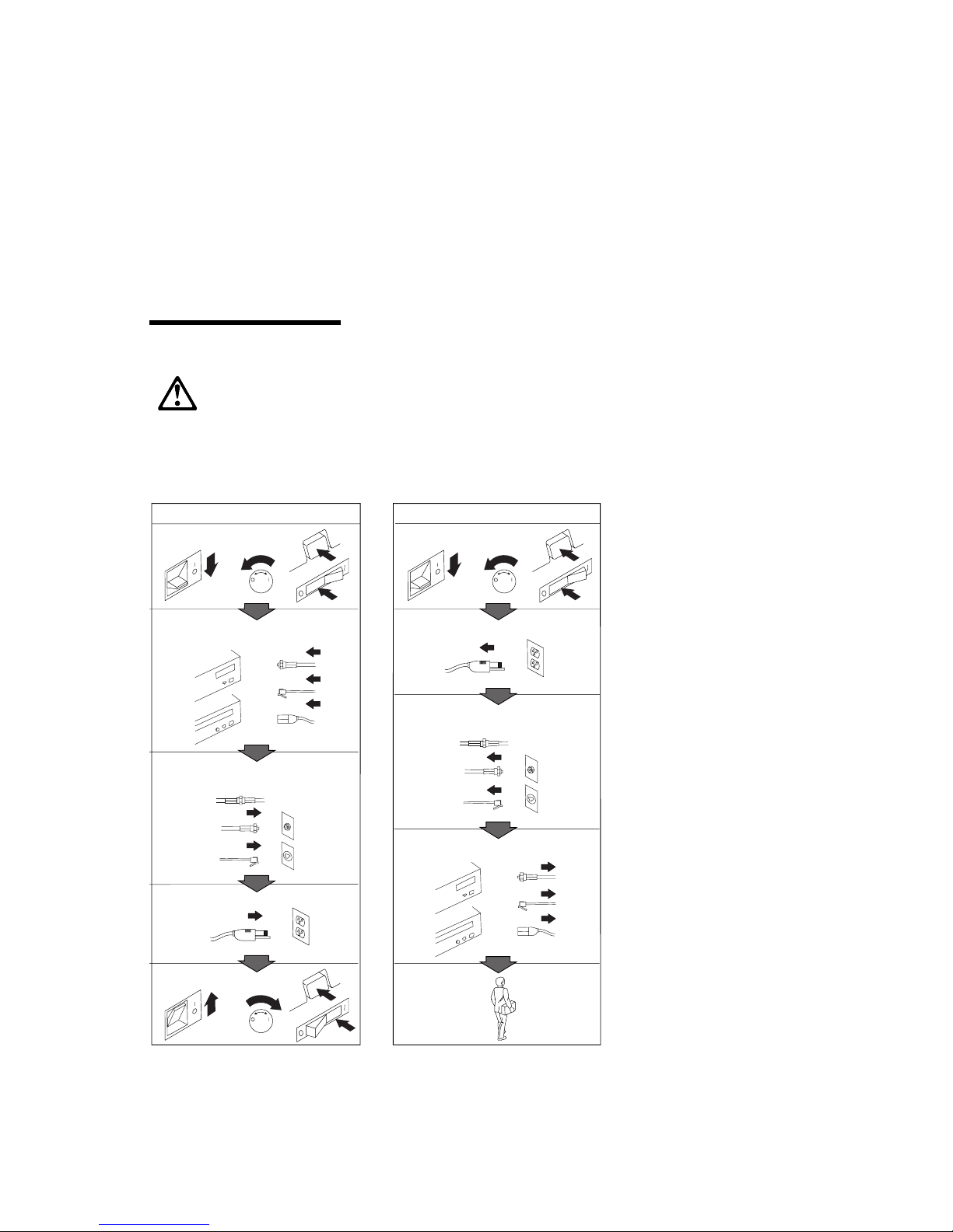
DANGER:
Electrical current from power, telephone, and communication
cables is hazardous. To avoid shock hazard, connect and
disconnect cables as shown below when installing, moving or
opening the covers of this product or attached devices. The
power cord must be used with a properly grounded outlet.
To Connect
Turn everything OFF.
To Disconnect
Turn everything OFF.
First, attach all cables to devices.
Attach signal cables to
receptacles.
Attach power cord to outlet.
Turn device ON.
12
In the U.K., by law, the telephone
cable must be connected after the
power cord.
1
First, remove power cord from
2
outlet.
Remove signal cables from
receptacles.
Remove all cables from devices.
In the U.K., by law, the power
cord must be disconnected after the
telephone line cable.
Copyright IBM Corp. 1998 v

Laser Compliance Statement
Some IBM Personal Computer models are equipped from the factory with a
CD-ROM drive. CD-ROM drives are also sold separately as options. The CD-ROM
drive is a laser product. The CD-ROM drive is certified in the U.S. to conform to
the requirements of the Department of Health and Human Services 21 Code of
Federal Regulations (DHHS 21 CFR) Subchapter J for Class 1 laser products.
Elsewhere, the drive is certified to conform to the requirements of the International
Electrotechnical Commission (IEC) 825 and CENELEC EN 60 825 for Class 1 laser
products.
When a CD-ROM drive is installed, note the following.
CAUTION:
Use of controls or adjustments or performance of procedures other than those
specified herein might result in hazardous radiation exposure.
Opening the CD-ROM drive could result in exposure to hazardous laser radiation.
There are no serviceable parts inside the CD-ROM drive. Do not open.
Some CD-ROM drives contain an embedded Class 3A or Class 3B laser diode. Note
the following.
DANGER
Laser radiation when open. Do not stare into the beam, do not view
directly with optical instruments, and avoid direct exposure to the beam.
vi Installing Options in Your Personal Computer

Lithium Battery Notice
CAUTION:
Danger of explosion if battery is incorrectly replaced.
When replacing the battery, use only IBM Part Number 33F8354 or an equivalent
type battery recommended by the manufacturer. The battery contains lithium
and can explode if not properly used, handled, or disposed of.
Do not:
Throw or immerse into water
Heat to more than 100°C (212°F)
Repair or disassemble
Dispose of the battery as required by local ordinances or regulations.
ATTENTION
Danger d'explosion en cas de remplacement incorrect de la batterie.
Remplacer uniquement par une batterie IBM de type 33F8354 ou d'un type
équivalent recommandé par le fabricant. La batterie contient du lithium et peut
exploser en cas de mauvaise utilisation, de mauvaise manipulation ou de mise au
rebut inappropriée.
Ne pas :
Lancer ou plonger dans l'eau
Chauffer à plus de 100°C (212°F)
Réparer ou désassembler
Mettre au rebut les batteries usagées conformément aux règlements locaux.
Safety Information vii
About This Book
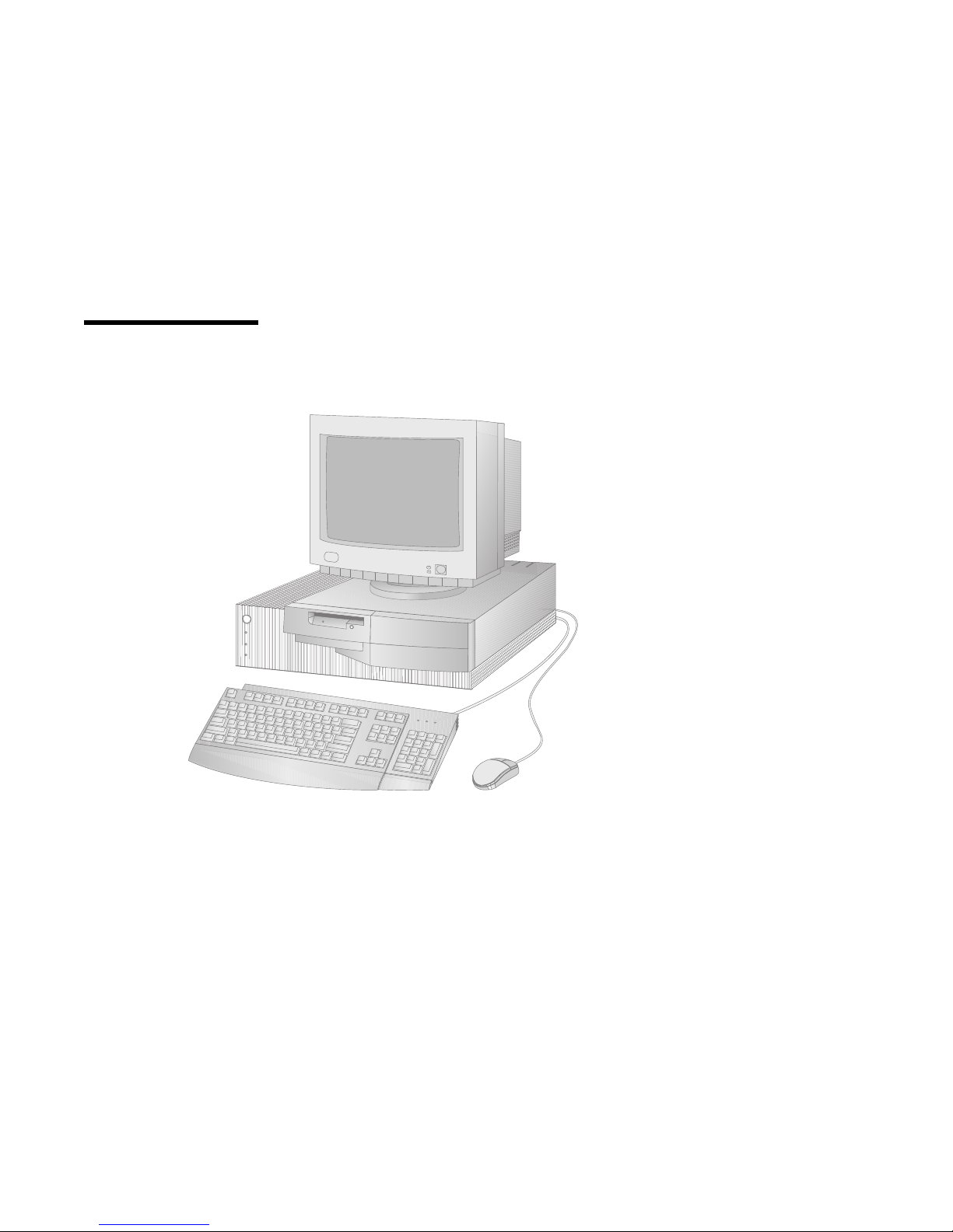
Thank you for selecting an IBM Personal Computer.
This book provides instructions for installing, removing, and replacing most options.
Also, this book contains information to help you decide which options to add to
your computer.
Note: The illustrations in this publication might be slightly different from your
hardware.
viii Copyright IBM Corp. 1998

How This Book Is Organized
This book contains the following chapters and appendixes:
Chapter 1, “Overview” provides an introduction to the options and features for
your computer. Safety precautions and handling techniques are discussed along
with the required tools you will need to install and remove options.
Chapter 2, “Preparing to Install and Remove Options” provides instructions for
removing the cover and cables for your computer and for locating the
components you want to work with.
Chapter 3, “Working with Options on the System Board” provides instructions
for locating, accessing, and working with options on the system board.
Chapter 4, “Working with Adapters” provides instructions for installing and
removing adapters.
Chapter 5, “Working with Internal Drives” provides instructions for installing
and removing internal drives.
Chapter 6, “Working with Security Options” describes features such as the
security U-bolt and erasing lost or forgotten passwords.
Chapter 7, “Completing the Installation” provides instructions for reassembling
your computer after you have finished installing options. Information about
using the Configuration/Setup Utility program is also provided.
Appendix A, “Changing the Battery” explains how to change your computer
backup battery and the precautions to take when handling and disposing of the
battery.
Appendix B, “Interrupt and DMA Resources” contains the default interrupt and
direct memory access (DMA) resources for your computer.
Appendix C, “Notices” contains IBM notices and trademark information.
About This Book ix

Related Publications
The following publications, together with this book, contain information about your
computer.
Setting Up Your Personal Computer
This publication contains instructions to help you set up your computer.
Using Your Personal Computer
This publication contains the following:
– Instructions for configuring, operating, and maintaining your computer
– Information on diagnosing and solving computer problems and how to get
help and service
– Warranty information
Understanding Your Personal Computer
This online publication (provided on the Ready-to-Configure Utility Program CD
and with the preinstalled software) includes general information about using
personal computers and in-depth information about the specific features of your
computer.
About Your Software
This publication (provided only with computers that have IBM-preinstalled
software) contains information about the preinstalled software package.
Your Ready-to-Configure Utility Program CD
This publication contains information about the Ready-to-Configure Utility
Program CD for your computer. The publication also contains instructions for
starting the CD.
The following publications contain more information about your computer.
Hardware Maintenance Manual
This separately purchased publication contains information for trained service
technicians. To obtain a copy, refer to the section on ordering publications in
the "Getting Help, Service, and Information" chapter in Using Your Personal
Computer. Also, this publication is on the World Wide Web at:
http://www.us.pc.ibm.com/cdt/hmm.html
x Installing Options in Your Personal Computer

Technical Information Manual
This publication contains more information about the technical aspects of your
computer. It is available on the World Wide Web at:
http://www.us.pc.ibm.com/support/desktop_support.html
About This Book xi

xii Installing Options in Your Personal Computer

Chapter 1. Overview
Adding hardware options to your computer is an easy way to increase its
capabilities. Instructions for removing, installing, and replacing options and
features are included in this book. When adding an option, use these instructions
along with the instructions that come with the option. If you have installed options
before, you might be able to perform some activities without detailed instructions.
This chapter provides a brief introduction to the options and features that are
discussed in this book. Also, important information about required tools, electrical
safety, and static-sensitive devices is discussed.
Important
Before you install or remove any option, read the safety procedures and
component-handling guidelines in this chapter. These precautions and
guidelines will help you work safely.
Refer to Using Your Personal Computer for general information on the use, operation,
and maintenance of your computer. Using Your Personal Computer also contains
information to help you solve problems and get repair service or other technical
assistance.
Copyright IBM Corp. 1998 1

Available Options and Features
The following are some of the available options and features that are discussed in
this book:
System board components
– System memory, called dual in-line memory modules (DIMMs)
– Microprocessor upgrades
– Jumper for clearing CMOS and erasing lost or forgotten passwords
– Flash recovery jumper
– Battery
Adapters
– Industry standard architecture (ISA) adapters
– Peripheral component interconnect (PCI) adapters
Internal drives
Security U-bolt
Additional options are available from IBM. An options package is available for
your computer that includes a floor stand, bottom cover, and rear cover. Although
these options are not covered in this book, they come with complete installation
instructions.
The following are some other available options and features for your computer. For
more information, refer to the documentation that comes with the optional
hardware.
Your computer can be remotely started using a Wake on LAN adapter. For more
information on Wake on LAN, see Using Your Personal Computer.
In some models, an audio adapter is preinstalled in one of the ISA slots. The
audio adapter is SoundBlaster compatible and provides a musical instrument
digital interface (MIDI) for connecting optional game controls or electronic
musical devices. Also, three ports are provided for connecting powered
speakers, an audio input device such as a portable CD-ROM, and a microphone.
To help with power management, you can add a modem and have your
computer start when a ring is detected by the modem. Using an internal
modem, you can use the Configuration/Setup Utility program to enable Modem
Ring Detect, or using an external modem, you can enable Serial Port Ring Detect.
For more information, see Using Your Personal Computer.
2 Installing Options in Your Personal Computer

IBM provides help in selecting drives, cables, and other options for your computer.
For the latest information about available options:
Within the United States, call 1-800-IBM-2YOU (1-800-426-2968), your IBM
reseller, or IBM marketing executive.
Within Canada, call 1-800-565-3344 or 1-800-465-7999.
Outside the United States and Canada, contact IBM, your IBM reseller, or IBM
marketing executive.
IBM maintains pages on the World Wide Web where you can get information about
IBM products and services, find the latest technical information, and download
device drivers and updates. Some of these pages are:
http://www.ibm.com Main IBM home page
http://www.pc.ibm.com IBM Personal Computer home
page
http://www.us.pc.ibm.com/desktop/ IBM Commercial Desktop home
page
http://www.us.pc.ibm.com/servers/ IBM PC Server and Netfinity
Server home page
http://www.us.pc.ibm.com/options/ IBM Options home page
http://www.us.pc.ibm.com/intellistation/world IBM IntelliStation home page
http://www.us.pc.ibm.com/thinkpad/ IBM ThinkPad home page
Tools Required
To install or remove options in your computer, you will need a flat-head
screwdriver. Any additional tools needed depend on the specific option and are
noted in the instructions that come with the option.
Chapter 1. Overview 3

Electrical Safety
CAUTION:
Electrical current from power, telephone, and communication cables can be
hazardous. To avoid any shock hazard, disconnect all power cords and cables as
described in the following information.
For your safety, always do the following before removing the cover:
1. Shut down all programs as described in your operating-system documentation.
2. Turn off the computer and any attached devices, such as printers, monitors, and
external drives.
Note: Personal computer users in the United Kingdom who have a modem or
fax machine attached to their computer must disconnect the telephone
line from the computer before unplugging any power cords (also known
as power cables). When the computer is reassembled, users must
reconnect the telephone line after plugging in the power cords.
3. Unplug all power cords from electrical outlets.
4. Disconnect all communication cables from external receptacles.
5. Disconnect all cables and power cords from the back of the computer.
Note: Do not reconnect any cables or power cords until you reassemble the
computer and put the cover back on.
CAUTION:
Never remove the cover on the power supply. If you have a problem with the
power supply, have your computer serviced.
4 Installing Options in Your Personal Computer

Handling Static-Sensitive Devices
Have you ever walked across a carpeted floor, then touched an object and received
a small electrical shock? That's static electricity, and although harmless to you, it
can seriously damage computer components and options.
Important
When you add an option, do not open the static-protective package containing
the option until you are instructed to do so.
When you handle options and other computer components, take these precautions
to avoid static electricity damage:
Limit your movement. Movement can cause static electricity to build up around
you.
Always handle components carefully. Handle adapters and memory-modules
by the edges. Never touch any exposed circuitry.
Prevent others from touching components.
When you are installing a new option, touch the static-protective package
containing the option to a metal expansion-slot cover or other unpainted metal
surface on the computer for at least two seconds. This reduces static electricity
in the package and your body.
When possible, remove the option and install it directly in the computer without
setting the option down. When this is not possible, place the static-protective
package that the option came in on a smooth, level surface and place the option
on it.
Do not place the option on the computer cover or other metal surface.
Chapter 1. Overview 5
Chapter 2. Preparing to Install and Remove Options
This chapter provides instructions for accessing and locating the options you want
to install or remove.
Disconnecting Cables and Removing the Cover
Before you begin
Read “Electrical Safety” on page 4 and “Handling Static-Sensitive Devices”
on page 5.
Remove any media (diskettes, compact discs, or tapes) from the drives, and
then turn off all attached devices and the computer.
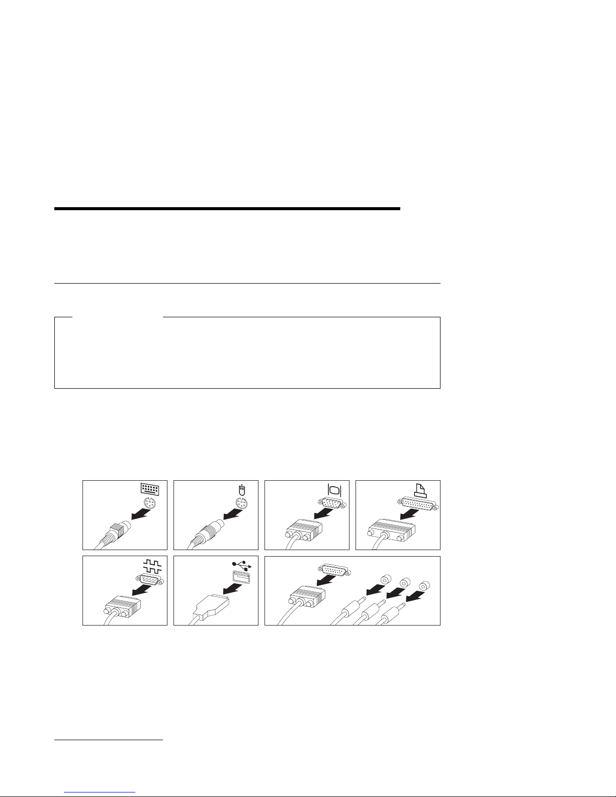
1 Disconnect all cables attached to the computer; this includes power cords,
input/output (I/O) cables, and any other cables connected to the computer.
Note: For more information on ports, including universal serial bus (USB),
refer to Understanding Your Personal Computer.
Keyboard Mouse
Serial
Device
USB
Device
Monitor
Audio
Device
1
Parallel
Device
MIDI
Out
Line In
Mic
1
For more information on Understanding Your Personal Computer, see “Related Publications” on page x.
6 Copyright IBM Corp. 1998
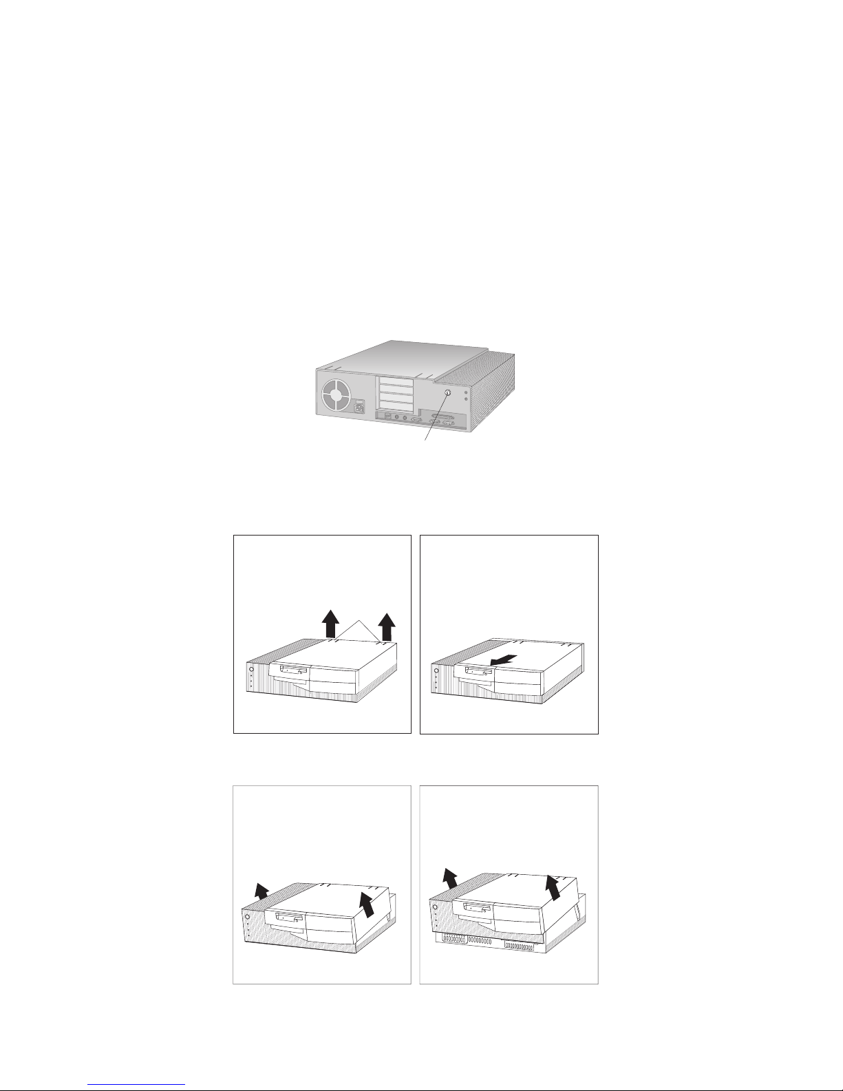
2 If key lock is present, unlock the computer cover. (The cover lock is located
on the rear of the computer in some models.)
Cover Lock
3 Find the tabs on the rear of the computer cover and lift them up; then gently
pull the cover toward you to release the back edge. Next, hold the cover by
the sides and pull it forward about half an inch.
Lift
Tabs
4 Lift the back edge and slide the cover forward until it comes free.
Chapter 2. Preparing to Install and Remove Options 7
Locating Components
Use the following information to help you locate components. Use it as a reference
when you need to install options or connect input/output devices.
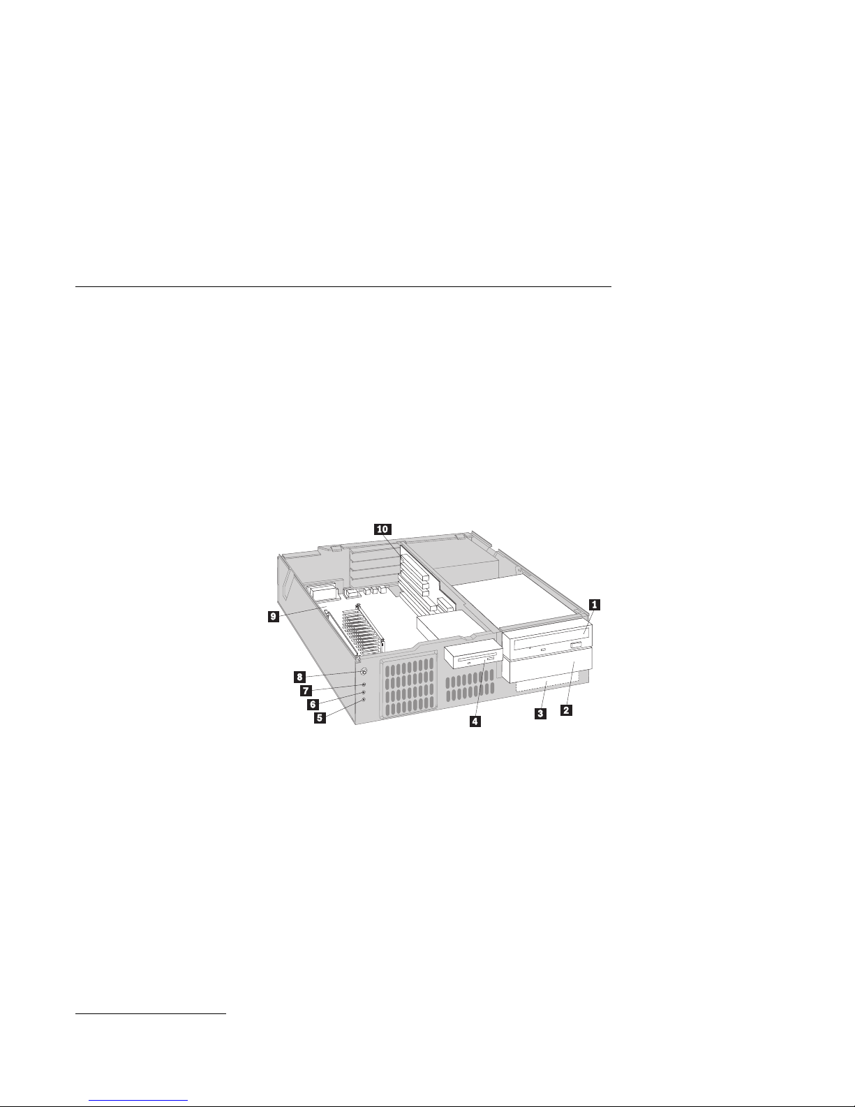
Internal View
The following illustration shows the internal view of your computer as seen from
the front. For information on removing the cover, see “Disconnecting Cables and
Removing the Cover” on page 6.
Note: The following illustration is for reference only.
.1/ Drive bay 1
.2/ Drive bay 2
.3/ Drive bay 3
.4/ Drive bay 4
.5/ Client LAN light
.6/ Hard disk drive light
.7/ Power-on light
.8/ On-off switch
.9/ System board
.1ð/ Riser card with
expansion slots
2
Your computer comes with a diskette drive installed in bay 4 and a hard disk drive
installed in bay 3. If your computer comes with a CD-ROM drive, it is installed in
bay 1.
For more information on drive bays, see “Working with Drives in Bays 1, 2, and 3”
on page 48 and “Working With Drives in Bay 4” on page 56.
2
The client LAN light is not used. This light is never activated even though a network adapter can be
installed in your computer.
8 Installing Options in Your Personal Computer
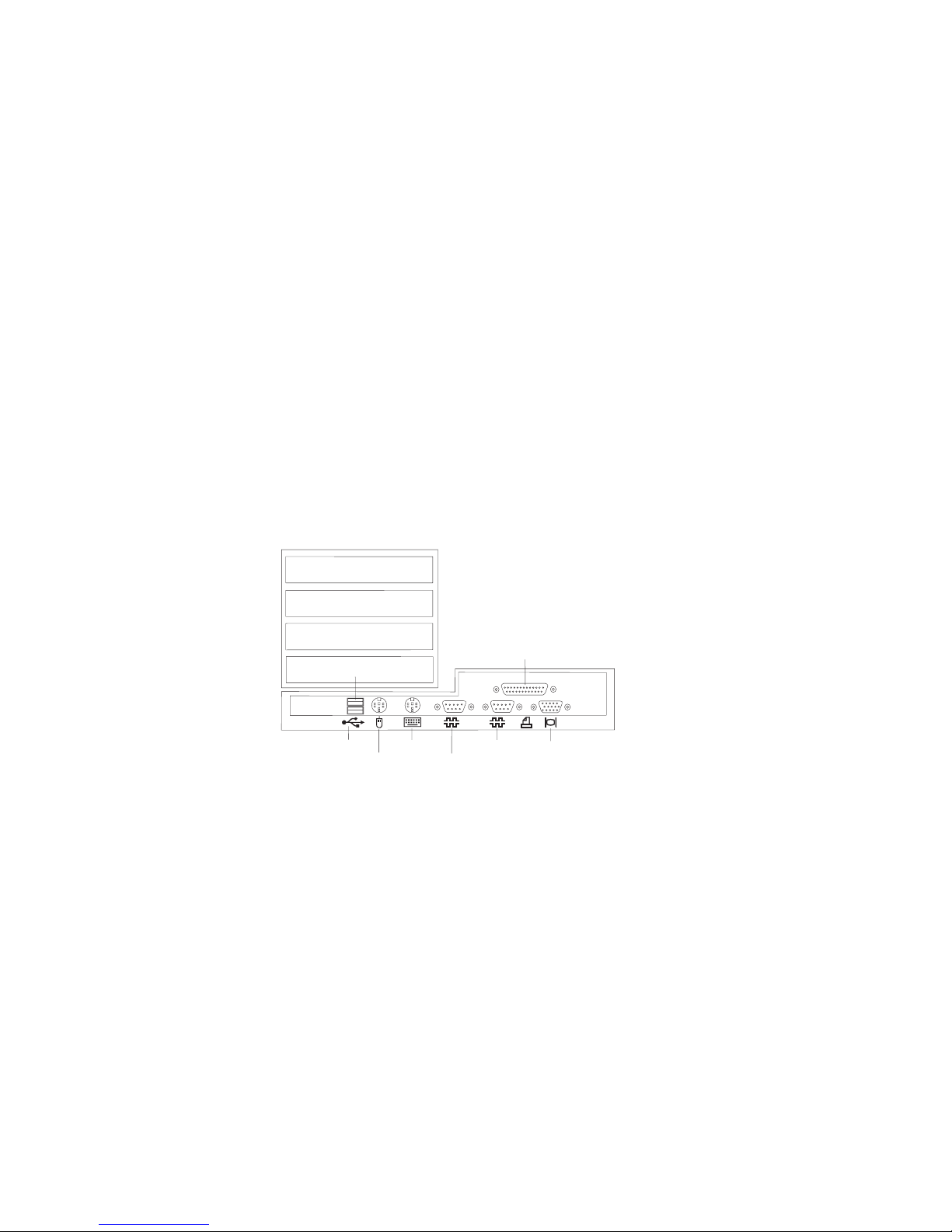
Input/Output Connectors
Input/output (I/O) connectors provide ports for transferring information into and
out of your computer. You can connect a variety of I/O devices to your computer,
including a monitor, keyboard, mouse, and printer. For more information on the
ports and their specific technologies, see Understanding Your Personal Computer.
The rear of your computer contains the I/O connectors. Adapters installed in
expansion slots might also provide I/O connectors. The following illustration
shows the I/O connectors on the rear of your computer.
Parallel
USB 1
USB 2
1
2
Mouse
Keyboard
Serial 2
2 1
Serial 1
Monitor
Chapter 2. Preparing to Install and Remove Options 9

Chapter 3. Working with Options on the System Board
This chapter provides information about system board options discussed in this
book.
The information in this chapter helps you identify parts on the system board. Also,
instructions are provided for accessing and installing options on the system board.
For example, you must have access to the system board to install system memory.
This chapter also provides instructions for installing, removing, and replacing
system board components, specifically system memory and the microprocessor. For
information on other system board components, see the appropriate section.
10 Copyright IBM Corp. 1998
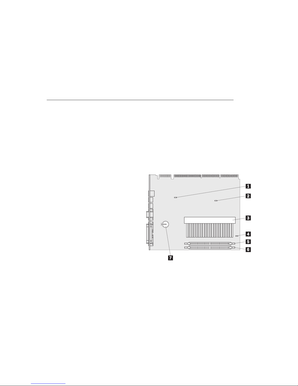
Identifying Parts on the System Board
The system board, also called the planar or motherboard, is the main circuit board in
your computer. It provides basic computer functions and supports a variety of
devices that are IBM-installed or that you can install later.
If you plan to install, remove, or replace hardware in your computer, you will need
to know the layout of the system board. The following illustration shows the layout
of the system board in your computer. The numbered pointers show the
components that are discussed in this book.
.1/ Recovery jumper
.2/ CMOS Clear jumper
.3/ Microprocessor connector
.4/ Asset EEPROM write protect jumper
.5/ Memory Module Connector 0 (Mem 0)
.6/ Memory Module Connector 1 (Mem 1)
.7/ Battery
Notes:
1. An illustration of the system board is provided on a label on the underside of
the computer cover.
2. The asset EEPROM write protect jumper is normally on pins 2 and 3. In this
position, the asset EEPROM is not write protected.
Chapter 3. Working with Options on the System Board 11

Working with System Memory
You can add memory to your computer to increase system performance. Your
computer has two connectors for installing system-memory modules. The
maximum amount of system memory your computer supports is 256 MB.
Note: To locate the memory connectors inside your computer, see “Identifying
Parts on the System Board” on page 11.
DIMM 0
DIMM 1
The memory modules your computer uses are dual inline memory modules (DIMMs).
The IBM-installed DIMMs that come with your computer are nonparity (NP) or
ECC (error correcting code) SDRAM (synchronous dynamic random access memory)
modules.
Note: If a mixture of nonparity (NP) and ECC DIMMs are installed, ECC will be
disabled.
When installing or replacing DIMMs, follow these rules:
Use only 3.3 V unbuffered DIMMs.
Each memory connector supports a maximum of 128 MB of SDRAM.
Install only ECC SDRAM DIMMS to enable ECC.
12 Installing Options in Your Personal Computer

Memory Configuration
When you are adding or removing memory, you can use any combination of DIMM
sizes 16, 32, 64, or 128 MB. A basic rule to follow is to fill each system memory
connector sequentially, starting at Mem 0.
The following table shows suggested memory configurations for your computer; this
table and additional information are also found on the underside of the computer
cover.
Note: Values in the following table are represented in megabytes (MB).
Table 1. Memory Configurations
Total Memory (MB) Mem 0 Mem 1
16 16 0
32 32 0
32 16 16
48 16 32
64 32 32
80 16 64
96 32 64
128 64 64
144 16 128
160 32 128
192 64 128
256 128 128
Chapter 3. Working with Options on the System Board 13
Installing a Memory Module
Before you begin
Read “Electrical Safety” on page 4 and “Handling Static-Sensitive Devices”
on page 5.
Read the instructions that come with the new system memory.
Turn off the computer and all other connected devices.
Disconnect all cables attached to the computer and remove the computer
cover (see “Disconnecting Cables and Removing the Cover” on page 6).
Note: For information on memory configuration, see Table 1 on page 13.
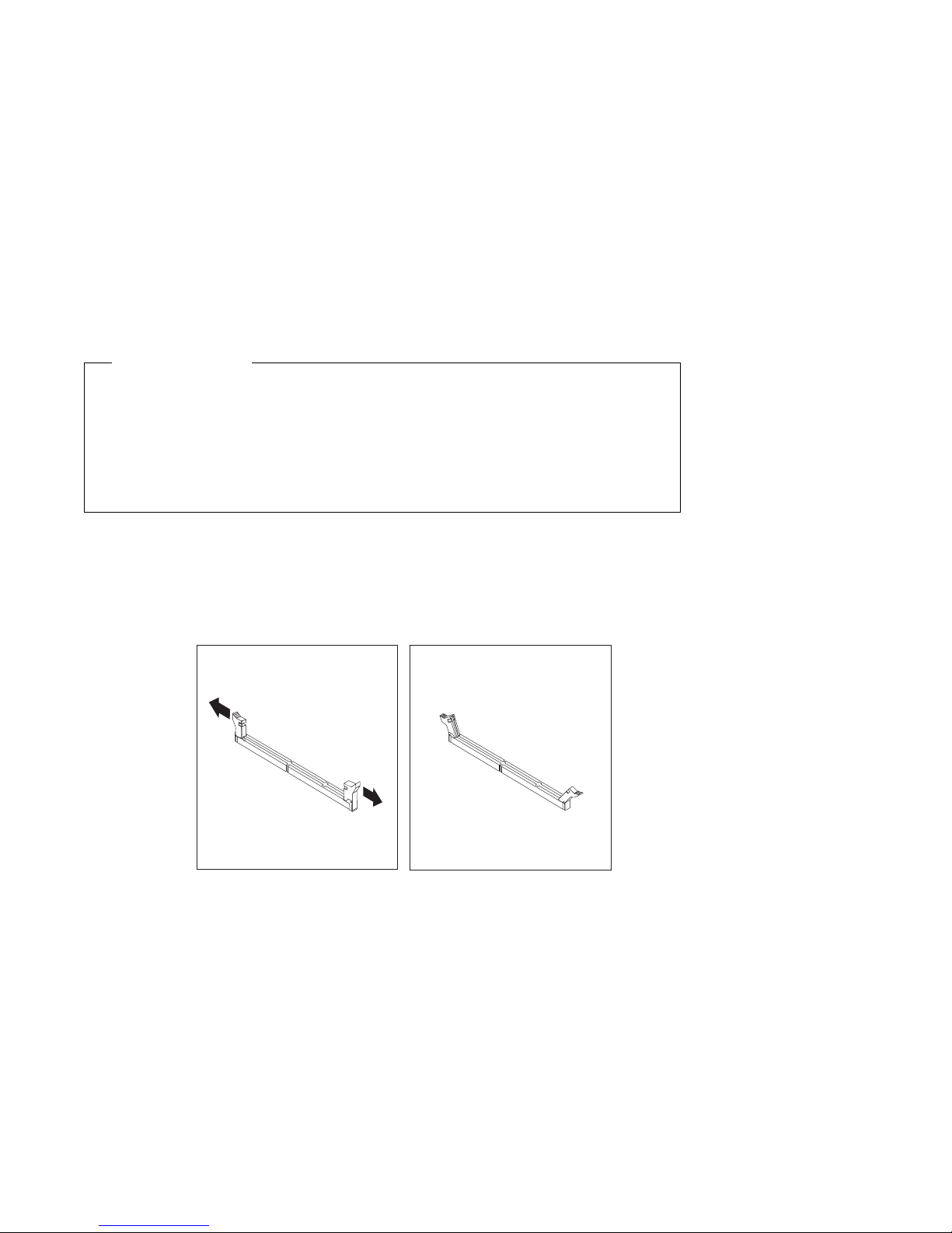
1 Be sure the retaining clips are in the open position, as shown in the second
illustration below. If the retaining clips are perpendicular with the connector,
push outward on them until they click open.
2 Touch the static-protective package containing the memory module to any
unpainted metal surface in the computer, and then remove the module.
3 Position the module above the connector so that the two notches on the
bottom edge of the module align properly with the connector.
14 Installing Options in Your Personal Computer
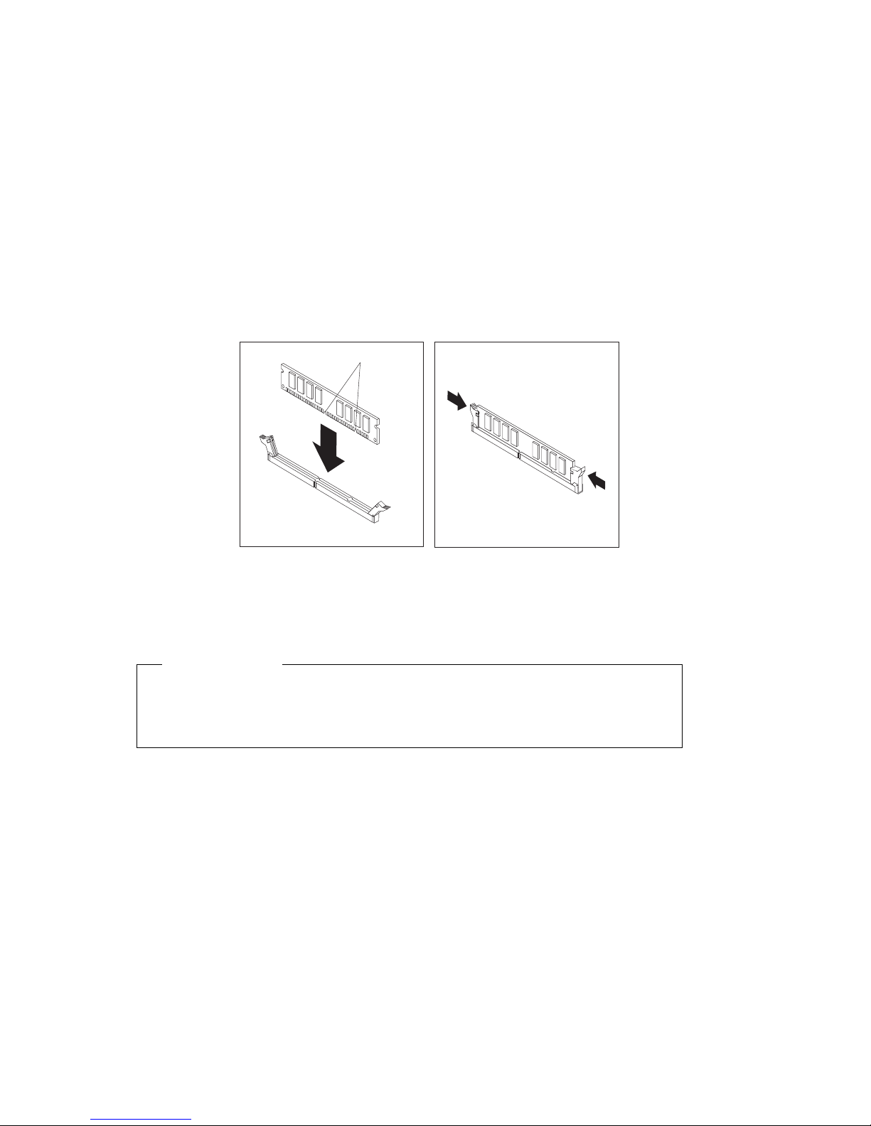
4 Firmly push the module straight down into the connector until the retaining
clips pop up and snugly fit around both ends of the module.
Notches
5 To install another memory module, repeat steps 1–4.
6 Go to the device-record form in Using Your Personal Computer and record this
installation.
What to do next
To work with another option, go to the appropriate section.
To complete the installation, go to Chapter 7, “Completing the Installation”
on page 68.
Chapter 3. Working with Options on the System Board 15
Removing a Memory Module
Before you begin
Read “Electrical Safety” on page 4 and “Handling Static-Sensitive Devices”
on page 5.
Turn off the computer and all other connected devices.
Disconnect all cables attached to the computer and remove the computer
cover (see “Disconnecting Cables and Removing the Cover” on page 6).
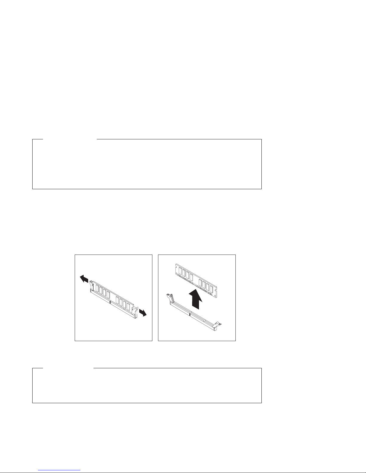
1 At both ends of the memory module connector, push outward on the retaining
clips until the module is loosened.
Note: Be careful not to push too hard on the retaining clips because the
module may abruptly eject from the connector.
2 Lift the memory module out of the connector.
3 Store the module in a static-protective package.
What to do next
To work with another option, go to the appropriate section.
To complete the installation, go to Chapter 7, “Completing the Installation”
on page 68.
16 Installing Options in Your Personal Computer
 Loading...