

Page 1

HardwareMaintenanceManual
ThinkPadL420,L421,andL520
Page 2

Note
Beforeusingthisinformationandtheproductitsupports,besuretoreadthegeneralinformationunder
AppendixA“Notices”onpage165
.
SecondEdition(April2011)
©CopyrightLenovo2011.
LIMITEDANDRESTRICTEDRIGHTSNOTICE:IfdataorsoftwareisdeliveredpursuantaGeneralServicesAdministration
“GSA”contract,use,reproduction,ordisclosureissubjecttorestrictionssetforthinContractNo.GS-35F-05925.
Page 3

Contents
Aboutthismanual...........iii
Chapter1.Safetyinformation.....1
Generalsafety................1
Electricalsafety...............2
Safetyinspectionguide............3
Handlingdevicesthataresensitivetoelectrostatic
discharge..................3
Groundingrequirements............4
Safetynotices(multilingualtranslations)......4
Lasercompliancestatement(multilingual
translations)................18
Chapter2.Importantservice
information..............25
StrategyforreplacingFRUs.........25
Strategyforreplacingaharddiskdrive...26
Importantnoticeforreplacingasystem
board................26
Howtouseerrormessage........26
StrategyforreplacingFRUsforCTO,CMV ,and
GAV...................26
Productdenition............26
FRUidenticationforCTO,CMV ,andGAV
products...............27
Powermanagement............40
Screenblankmode...........40
Sleep(standby)mode..........40
Hibernationmode...........41
Symptom-to-FRUindex...........41
Numericerrorcodes..........42
Errormessages............44
No-beepsymptoms...........44
LCD-relatedsymptoms.........44
Intermittentproblems..........45
Undeterminedproblems.........45
Chapter5.Statusindicators.....47
Chapter6.Fnkeycombinations...49
Chapter7.FRUreplacement
notices................53
Screwnotices...............53
Retainingserialnumbers...........54
Restoringtheserialnumberofthesystem
unit.................54
RetainingtheUUID...........54
ReadingorwritingtheECAinformation...55
Chapter3.Generalcheckout.....29
Whattodorst..............29
Checkoutguide..............30
DiagnosticsusingPC-DoctorforDOS....30
LenovoThinkVantageT oolbox.......33
FRUtests...............33
Powersystemcheckout...........34
Checkingtheacpoweradapter......34
Checkingoperationalcharging......35
Checkingthebatterypack........35
Checkingthebackupbattery.......36
Chapter4.Relatedservice
information..............37
RestoringthefactorycontentsbyusingRecovery
DiscSet.................37
Passwords................38
Power-onpassword...........38
Hard-diskpassword...........38
Supervisorpassword..........39
Howtoremovethepower-onpassword...39
Howtoremovethehard-diskpassword...39
Chapter8.Removingandreplacinga
FRU..................57
1010Batterypack.............57
1020ExpressCardblankbezelandMediaCard
blankbezel................58
1030Opticaldriveortravelcover.......60
1040Thermalcover.............61
1050Harddiskdriveorsolidstatedrive
assembly.................62
1060DIMM................65
1070Fanassembly.............66
1080CPU................68
1090SIMslotcover............69
1110WirelessWANslotcoverandPCIExpress
MiniCardforwirelessWAN..........71
1110mSATAsolidstatedrive.........73
1120Palmrestassemblywithcables......74
1130PCIExpressMiniCardforwirelessLAN..78
1140Backupbattery............80
1150Bluetoothdaughtercard........80
1160MediaCardReaderslotboardandMedia
CardReadercableassembly.........81
1170Keyboard..............83
©CopyrightLenovo2011
i
Page 4

1180Keyboardbezel............85
1190LCDunit...............87
2010T opshieldingassembly.........90
2020Systemboardassembly.........93
2030USBconnectorboardandUSBcable
assembly.................98
2040DC-incableandbasecover.......100
2050LCDfrontbezel............103
2060Speakerassembly...........104
2070Integratedcamera...........105
2080Antennaassembly...........106
2090Hinges,LCDpanel,LCDcable,andLCDrear
coverassembly..............108
Chapter9.Locations........113
Frontview................113
Rearview.................114
Bottomview...............114
Keyboard.................152
Miscellaneousparts............153
acpoweradapters.............154
Powercords...............155
Recoverydiscs..............156
WindowsXPProfessional(32bit)DVDs...156
WindowsVistaHomeBasic(32bit)DVDs..157
WindowsVistaBusiness(32bit)DVDs...157
Windows7HomeBasic(32bit)DVDs....158
Windows7HomePremium(32bit)DVDs..158
Windows7HomePremium(64bit)DVDs..159
Windows7Professional(32bit)DVDs....160
Windows7Professional(64bit)DVDs....160
Windows7Ultimate(32bit)DVDs.....162
Windows7Ultimate(64bit)DVDs.....162
Windows7Starter(32bit)DVDs......162
Commonservicetools...........163
Chapter10.Partslist........115
Overall..................116
LCDFRUs................144
AppendixA.Notices........165
Electronicemissionsnotices.........166
Trademarks................166
iiHardwareMaintenanceManual
Page 5

Aboutthismanual
ThismanualcontainsserviceandreferenceinformationforthefollowingThinkPad
ThinkPadL420
MachineType(MT)7826,7827,7829,7853,7854,and7856
ThinkPadL421
MT7826,7827,7829,7853,7854,and7856
ThinkPadL520
MT5015,5016,5017,5019,7859,and7860
®
Notebookproducts.
Usethismanualalongwiththeadvanceddiagnosticteststotroubleshootproblems.
Important:
ThismanualisintendedonlyfortrainedservicetechnicianswhoarefamiliarwithThinkPadproducts.Use
thismanualalongwiththeadvanceddiagnosticteststotroubleshootproblemseffectively.
BeforeservicingaThinkPadproduct,besuretoreadalltheinformationunderChapter1“Safety
information”onpage1
andChapter2“Importantserviceinformation”onpage25.
©CopyrightLenovo2011
iii
Page 6

ivHardwareMaintenanceManual
Page 7

Chapter1.Safetyinformation
Thischapterpresentsfollowingsafetyinformationthatyouneedtobefamiliarwithbeforeyouservice
aThinkPadNotebook.
•“Generalsafety”onpage1
•“Electricalsafety”onpage2
•“Safetyinspectionguide”onpage3
•“Handlingdevicesthataresensitivetoelectrostaticdischarge”onpage3
•“Groundingrequirements”onpage4
•“Safetynotices(multilingualtranslations)”onpage4
•“Lasercompliancestatement(multilingualtranslations)”onpage18
Generalsafety
Followtheserulestoensuregeneralsafety:
•Observegoodhousekeepingintheareaofthemachinesduringandaftermaintenance.
•Whenliftinganyheavyobject:
1.Makesurethatyoucanstandsafelywithoutslipping.
2.Distributetheweightoftheobjectequallybetweenyourfeet.
3.Useaslowliftingforce.Nevermovesuddenlyortwistwhenyouattempttolift.
4.Liftbystandingorbypushingupwithyourlegmuscles;thisactionremovesthestrainfromthe
musclesinyourback.Donotattempttoliftanyobjectthatweighsmorethan16kg(35lb)orthat
youthinkistooheavyforyou.
•Donotperformanyactionthatcauseshazardstothecustomer,orthatmakestheequipmentunsafe.
•Beforeyoustartthemachine,makesurethatotherservicetechniciansandthecustomer'spersonnelare
notinahazardousposition.
•Placeremovedcoversandotherpartsinasafeplace,awayfromallpersonnel,whileyouareservicing
themachine.
•Keepyourtoolcaseawayfromwalkareassothatotherpeoplewillnottripoverit.
•Donotwearlooseclothingthatcanbetrappedinthemovingpartsofamachine.Makesurethatyour
sleevesarefastenedorrolledupaboveyourelbows.Ifyourhairislong,fastenit.
•Inserttheendsofyournecktieorscarfinsideclothingorfastenitwithanonconductiveclip,about8
centimeters(3inches)fromtheend.
•Donotwearjewelry,chains,metal-frameeyeglasses,ormetalfastenersforyourclothing.
Attention:Metalobjectsaregoodelectricalconductors.
•Wearsafetyglasseswhenyouarehammering,drilling,soldering,cuttingwire,attachingsprings,using
solvents,orworkinginanyotherconditionsthatmightbehazardoustoyoureyes.
•Afterservice,reinstallallsafetyshields,guards,labels,andgroundwires.Replaceanysafetydevice
thatiswornordefective.
•Reinstallallcoverscorrectlybeforereturningthemachinetothecustomer.
•Fanlouversonthemachinehelptopreventoverheatingofinternalcomponents.Donotobstructfan
louversorcoverthemwithlabelsorstickers.
©CopyrightLenovo2011
1
Page 8

Electricalsafety
Observethefollowingruleswhenworkingonelectricalequipment.
Important:
Useonlyapprovedtoolsandtestequipment.Somehandtoolshavehandlescoveredwithasoftmaterial
thatdoesnotinsulateyouwhenworkingwithliveelectricalcurrents.
Manycustomershave,neartheirequipment,rubberoormatsthatcontainsmallconductivebersto
decreaseelectrostaticdischarges.Donotusethistypeofmattoprotectyourselffromelectricalshock.
•Findtheroomemergencypower-off(EPO)switch,disconnectingswitch,orelectricaloutlet.Ifanelectrical
accidentoccurs,youcanthenoperatetheswitchorunplugthepowercordquickly.
•Donotworkaloneunderhazardousconditionsornearequipmentthathashazardousvoltages.
•Disconnectallpowerbefore:
–Performingamechanicalinspection
–Workingnearpowersupplies
–Removingorinstallingmainunits
•Beforeyoustarttoworkonthemachine,unplugthepowercord.Ifyoucannotunplugit,askthecustomer
topower-offthewallboxthatsuppliespowertothemachine,andtolockthewallboxintheoffposition.
•Ifyouneedtoworkonamachinethathasexposedelectricalcircuits,observethefollowingprecautions:
–Ensurethatanotherperson,familiarwiththepower-offcontrols,isnearyou.
Attention:Anotherpersonmustbetheretoswitchoffthepower,ifnecessary.
–Useonlyonehandwhenworkingwithpowered-onelectricalequipment;keeptheotherhandinyour
pocketorbehindyourback.
Attention:Anelectricalshockcanoccuronlywhenthereisacompletecircuit.Byobservingtheabove
rule,youmaypreventacurrentfrompassingthroughyourbody.
–Whenusingtesters,setthecontrolscorrectlyandusetheapprovedprobeleadsandaccessoriesfor
thattester.
–Standonsuitablerubbermats(obtainedlocally,ifnecessary)toinsulateyoufromgroundssuchas
metaloorstripsandmachineframes.
Observethespecialsafetyprecautionswhenyouworkwithveryhighvoltages;Instructionsforthese
precautionsareinthesafetysectionsofmaintenanceinformation.Useextremecarewhenmeasuring
highvoltages.
•Regularlyinspectandmaintainyourelectricalhandtoolsforsafeoperationalcondition.
•Donotusewornorbrokentoolsandtesters.
•Neverassumethatpowerhasbeendisconnectedfromacircuit.First,checkthatithasbeenpoweredoff.
•Alwayslookcarefullyforpossiblehazardsinyourworkarea.Examplesofthesehazardsaremoistoors,
nongroundedpowerextensioncables,powersurges,andmissingsafetygrounds.
•Donottouchliveelectricalcircuitswiththereectivesurfaceofaplasticdentalmirror.Thesurfaceis
conductive;suchtouchingcancausepersonalinjuryandmachinedamage.
•Donotservicethefollowingpartswiththepoweronwhentheyareremovedfromtheirnormaloperating
placesinamachine:
–Powersupplyunits
–Pumps
–Blowersandfans
–Motorgenerators
–Similarunitstolistedabove
Thispracticeensurescorrectgroundingoftheunits.
•Ifanelectricalaccidentoccurs:
2HardwareMaintenanceManual
Page 9

–Usecaution;donotbecomeavictimyourself.
–Switchoffpower.
–Sendanotherpersontogetmedicalaid.
Safetyinspectionguide
Thepurposeofthisinspectionguideistoassistyouinidentifyingpotentiallyunsafeconditions.Aseach
machinewasdesignedandbuilt,requiredsafetyitemswereinstalledtoprotectusersandservicetechnicians
frominjury.Thisguideaddressesonlythoseitems.Y oushouldusegoodjudgmenttoidentifypotential
safetyhazardsduetoattachmentofnon- ThinkPadfeaturesoroptionsnotcoveredbythisinspectionguide.
Ifanyunsafeconditionsarepresent,youmustdeterminehowserioustheapparenthazardcouldbeand
whetheryoucancontinuewithoutrstcorrectingtheproblem.
Considertheseconditionsandthesafetyhazardstheypresent:
•Electricalhazards,especiallyprimarypower(primaryvoltageontheframecancauseseriousorfatal
electricalshock)
•Explosivehazards,suchasadamagedCRTfaceorabulgingcapacitor
•Mechanicalhazards,suchaslooseormissinghardware
Todeterminewhetherthereareanypotentiallyunsafeconditions,usethefollowingchecklistatthebeginning
ofeveryservicetask.Beginthecheckswiththepoweroff,andthepowercorddisconnected.
Checklist:
1.Checkexteriorcoversfordamage(loose,broken,orsharpedges).
2.Poweroffthecomputer.Disconnectthepowercord.
3.Checkthepowercordfor:
a.Athird-wiregroundconnectoringoodcondition.Useametertomeasurethird-wireground
continuityfor0.1ohmorlessbetweentheexternalgroundpinandtheframeground.
b.Thepowercordshouldbethetypespeciedinthepartslist.
c.Insulationmustnotbefrayedorworn.
4.Checkforcrackedorbulgingbatteries.
5.Removethecover.
6.Checkforanyobviousnon-ThinkPadalterations.Usegoodjudgmentastothesafetyofany
non-ThinkPadalterations.
7.Checkinsidetheunitforanyobviousunsafeconditions,suchasmetallings,contamination,wateror
otherliquids,orsignsofreorsmokedamage.
8.Checkforworn,frayed,orpinchedcables.
9.Checkthatthepower-supplycoverfasteners(screwsorrivets)havenotbeenremovedortamperedwith.
Handlingdevicesthataresensitivetoelectrostaticdischarge
Anycomputerpartcontainingtransistorsorintegratedcircuits(ICs)shouldbeconsideredsensitiveto
electrostaticdischarge(ESD.)ESDdamagecanoccurwhenthereisadifferenceinchargebetweenobjects.
ProtectagainstESDdamagebyequalizingthechargesothatthemachine,thepart,theworkmat,andthe
personhandlingthepartareallatthesamecharge.
Notes:
1.Useproduct-specicESDprocedureswhentheyexceedtherequirementsnotedhere.
Chapter1.Safetyinformation3
Page 10

2.MakesurethattheESDprotectivedevicesyouusehavebeencertied(ISO9000)asfullyeffective.
WhenhandlingESD-sensitiveparts:
•Keepthepartsinprotectivepackagesuntiltheyareinsertedintotheproduct.
•Avoidcontactwithotherpeople.
•Wearagroundedwriststrapagainstyourskintoeliminatestaticonyourbody.
•Preventthepartfromtouchingyourclothing.Mostclothingisinsulativeandretainsachargeevenwhen
youarewearingawriststrap.
•Useagroundedworkmattoprovideastatic-freeworksurface.Thematisespeciallyusefulwhen
handlingESD-sensitivedevices.
•Selectagroundingsystem,suchasthoselistedbelow,toprovideprotectionthatmeetsthespecic
servicerequirement.
Note:TheuseofagroundingsystemtoguardagainstESDdamageisdesirablebutnotnecessary.
–AttachtheESDgroundcliptoanyframeground,groundbraid,orgreen-wireground.
–Whenworkingonadouble-insulatedorbattery-operatedsystem,useanESDcommongroundor
referencepoint.Youcanusecoaxorconnector-outsideshellsonthesesystems.
–Usetheroundgroundprongoftheacplugonac-operatedcomputers.
Groundingrequirements
Electricalgroundingofthecomputerisrequiredforoperatorsafetyandcorrectsystemfunction.Proper
groundingoftheelectricaloutletcanbeveriedbyacertiedelectrician.
Safetynotices(multilingualtranslations)
Thesafetynoticesinthissectionareprovidedinthefollowinglanguages:
•English
•Arabic
•BrazilianPortuguese
•French
•German
•Hebrew
•Japanese
•Korean
•Spanish
•TraditionalChinese
DANGER
DANGER
4HardwareMaintenanceManual
Page 11
DANGER
DANGER
DANGER
DANGER
DANGER
Chapter1.Safetyinformation5
Page 12

DANGER
6HardwareMaintenanceManual
Page 13

PERIGO
PERIGO
PERIGO
Chapter1.Safetyinformation7
Page 14
PERIGO
PERIGO
PERIGO
PERIGO
PERIGO
8HardwareMaintenanceManual
Page 15

DANGER
DANGER
DANGER
DANGER
DANGER
Chapter1.Safetyinformation9
Page 16

DANGER
DANGER
DANGER
VORSICHT
VORSICHT
10HardwareMaintenanceManual
Page 17

VORSICHT
VORSICHT
VORSICHT
VORSICHT
VORSICHT
VORSICHT
Chapter1.Safetyinformation11
Page 18

12HardwareMaintenanceManual
Page 19

Chapter1.Safetyinformation13
Page 20

14HardwareMaintenanceManual
Page 21
PELIGRO
Chapter1.Safetyinformation15
Page 22

PELIGRO
PELIGRO
PELIGRO
PELIGRO
PELIGRO
PELIGRO
16HardwareMaintenanceManual
Page 23
PELIGRO
Chapter1.Safetyinformation17
Page 24

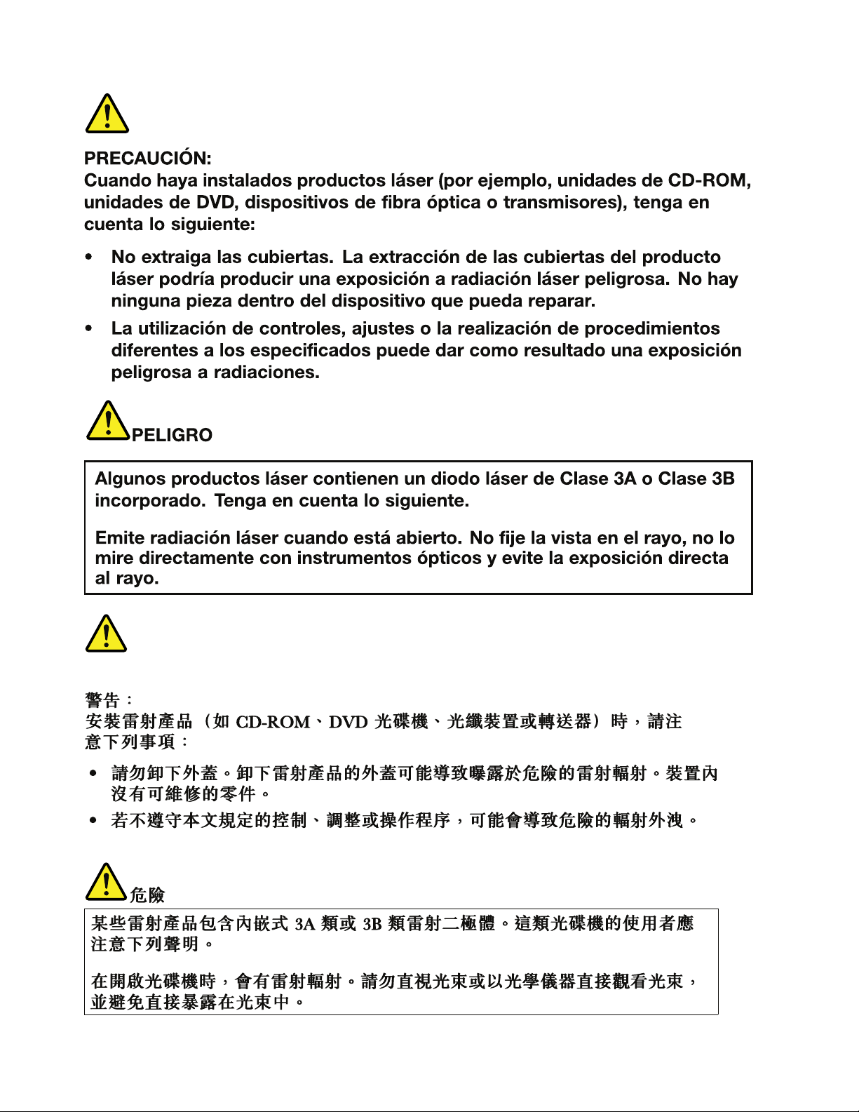
Lasercompliancestatement(multilingualtranslations)
Thelasercompliancestatementsinthissectionareprovidedinthefollowinglanguages:
•English
•Arabic
•BrazilianPortuguese
•French
•German
•Hebrew
•Japanese
•Korean
•Spanish
•TraditionalChinese
18HardwareMaintenanceManual
Page 25

Chapter1.Safetyinformation19
Page 26

20HardwareMaintenanceManual
Page 27

Chapter1.Safetyinformation21
Page 28

22HardwareMaintenanceManual
Page 29

Chapter1.Safetyinformation23
Page 30
24HardwareMaintenanceManual
Page 31

Chapter2.Importantserviceinformation
Thischapterpresentsfollowingimportantserviceinformationthatappliestoallmachinetypessupportedby
thismanual:
•“StrategyforreplacingFRUs”onpage25
–“Strategyforreplacingaharddiskdrive”onpage26
–“Importantnoticeforreplacingasystemboard”onpage26
–“Howtouseerrormessage”onpage26
•“StrategyforreplacingFRUsforCTO,CMV,andGAV”onpage26
–“Productdenition”onpage26
–“FRUidenticationforCTO,CMV ,andGAVproducts”onpage27
Important:
•AdvisecustomerstocontacttheLenovoCustomerSupportCenteriftheyneedanyassistancein
obtainingorinstallinganysoftwarexes,drivers,andBIOSdownloads.TelephonenumbersforLenovo
Supportareavailableat:
http://www.lenovo.com/support/phone
•SystemDisassembly/ReassemblyvideosthatshowtheFRUremovalsorreplacementsfortheLenovo
authorizedservicetechniciansareavailableinthefollowingsupportsite:
http://www.lenovoservicetraining.com/ion/
•AdvisecustomerstocontacttheCustomerSupportCenterat800-426-7378iftheyneedassistancein
obtainingorinstallinganysoftwarexes,drivers,andBIOSdownloads.
•CustomersinCanadashouldcalltheCustomerSupportCenterat800-565-3344forassistanceor
downloadinformation.
®
StrategyforreplacingFRUs
Beforereplacingparts:
Makesurethatallsoftwarexes,drivers,andBIOSdownloadsareinstalledbeforereplacinganyFRUs
listedinthismanual.
Afterasystemboardisreplaced,ensurethatthelatestBIOSisloadedtothesystemboardbefore
completingtheserviceaction.
Todownloadsoftwarexes,drivers,andBIOS,doasfollows:
1.Gotohttp://www.lenovo.com/support.
2.EntertheproductnumberofthecomputerorpressAuto-detectbuttononthescreen.
3.SelectDownloads&Drivers.
4.Followthedirectionsonthescreenandinstallthenecessarysoftware.
UsethefollowingstrategytopreventunnecessaryexpenseforreplacingandservicingFRUs:
•IfyouareinstructedtoreplaceaFRUbutthereplacementdoesnotcorrecttheproblem,reinstall
theoriginalFRUbeforeyoucontinue.
•Somecomputershavebothaprocessorboardandasystemboard.Ifyouareinstructedtoreplaceeither
theprocessorboardorthesystemboard,andreplacingoneofthemdoesnotcorrecttheproblem,
reinstallthatboard,andthenreplacetheotherone.
©CopyrightLenovo2011
25
Page 32

•IfanadapteroradeviceconsistsofmorethanoneFRU,anyoftheFRUsmaybethecauseoftheerror.
Beforereplacingtheadapterordevice,removetheFRUs,onebyone,toseeifthesymptomschange.
ReplaceonlytheFRUthatchangedthesymptoms.
Attention:Thesetupcongurationonthecomputeryouareservicingmayhavebeencustomized.Running
AutomaticCongurationmayalterthesettings.Notethecurrentcongurationsettings(usingtheView
Congurationoption);then,whenservicehasbeencompleted,verifythatthosesettingsremainineffect.
Strategyforreplacingaharddiskdrive
Alwaystrytorunalow-levelformatbeforereplacingaharddiskdrive.Thiswillcauseallcustomerdataon
theharddisktobelost.Besurethatthecustomerhasacurrentbackupofthedatabeforedoingthistask.
Attention:Thedrivestartupsequenceinthecomputeryouareservicingmayhavebeenchanged.Be
extremelycarefulduringwriteoperationssuchascopying,saving,orformatting.Ifyouselectanincorrect
drive,dataorprogramscanbeoverwritten.
Importantnoticeforreplacingasystemboard
Somecomponentsmountedonasystemboardareverysensitive.Improperhandlingofasystemboardcan
causedamagetothosecomponents,andmaycauseasystemmalfunction.
Attention:Whenhandlingasystemboard:
•Donotdropasystemboardorapplyanyexcessiveforcetoit.
•Avoidroughhandlingofanykind.
•AvoidbendingasystemboardandhardpushingtopreventcrackingateachBGA(BallGridArray)chipset.
Howtouseerrormessage
Usetheerrorcodesdisplayedonthescreentodiagnosefailures.Ifmorethanoneerrorcodeisdisplayed,
beginthediagnosiswiththersterrorcode.Whatevercausesthersterrorcodemayalsocausefalseerror
codes.Ifnoerrorcodeisdisplayed,seewhethertheerrorsymptomislistedintheSymptom-to-FRU
Indexforthecomputeryouareservicing.
StrategyforreplacingFRUsforCTO,CMV ,andGAV
Productdenition
DynamicCongureToOrder(CTO)
ThisprovidestheabilityforacustomertocongureanIBM
thiscongurationsenttofulllment,whereitisbuiltandshippeddirectlytothecustomer.Themachine
label,ProductEntitlementWarehouse(PEW),eSupport,andtheHMMwillloadtheseproductsasthe4-digit
MTand3-digitmodel,wheremodel=“CTO”(Example:1829-CTO).
CustomModelVariant(CMV)
ThisisauniquecongurationthathasbeennegotiatedbetweenIBMorLenovoandthecustomer.Aunique
4-digitMTand3-digitmodelisprovidedtothecustomertoplaceorders(Example:1829-W15).ACMV
isaspecialbidoffering.Therefore,itisNOTgenerallyannounced.
•TheMTMportionofthemachinelabelisthe4-digitMTand3-digitmodel,wheremodel=“CTO”
(Example:1829-CTO).ThePRODUCTIDportionofthemachinelabelisthe4-digitMTand3-digitCMV
model(Example:1829-W15).
•ThePEWrecordisthe4-digitMTand3-digitmodel,wheremodel=“CTO”(Example:1829-CTO).
®
oraLenovosolutionfromaneSite,andhave
26HardwareMaintenanceManual
Page 33

•eSupportwillshowboththeCTOandCMVmachinetypemodels(Example:1829-CTOand1829-W15
willbefoundontheeSupportsite.)
•TheHMMwillhavethe4-digitMTand3-digitCTOmodelonly(Example:1829-CTO).Again,CMVsare
custommodelsandarenotfoundintheHMM.
GeneralAnnounceVariant(GAV)
Thisisastandardmodel(xedconguration).GAVsareannouncedandofferedtoallcustomers.TheMTM
portionofthemachinelabelisa4-digitMTand3-digitmodel,wheremodel=a“xedpartnumber”,not
“CTO”(Example:1829-F1U).Also,PEW,eSupport,andtheHMMwilllisttheseproductsunderthesame
xedmodelnumber.
FRUidenticationforCTO,CMV,andGAVproducts
TherearethreeinformationresourcestoidentifywhichFRUsareusedtosupportCTO,CMV ,andGAV
products.ThesesourcesarePEW ,eSupport,andtheHMM.
UsingPEW
•PEWistheprimarysourceforidentifyingFRUpartnumbersandFRUdescriptionsforthekeycommodities
forCTO,CMVandGAVproductsataMT-serialnumberlevel.Anexampleofkeycommoditiesarehard
diskdrives,systemboards,microprocessors,LiquidCrystalDisplays(LCDs),andmemory.
•Remember,allCTOandCMVproductsareloadedinPEWunderthe4-digitMTand3-digitmodel,where
model=“CTO”(Example:1829-CTO).GAVsareloadedinPEWunderthe4-digitMTand3-digitmodel,
wheremodel=a“xedpartnumber”,not“CTO”(Example:1829-F1U).
•PEWcanbeaccessedatthefollowingWebsite:
http://www.lenovo.com/support/site.wss/document.do?lndocid=LOOK-WARNTY
SelectWarrantylookup.InputtheMTandtheSerialnumberandthelistofkeycommoditieswillbe
returnedinthePEWrecordunderCOMPONENTINFORMA TION.
UsingeSupport
ForKeyCommodities(Examples-harddiskdrive,systemboard,microprocessor,LCD,andmemory)
•eSupportcanbeusedtoviewthelistofkeycommoditiesbuiltinaparticularmachineserial(thisisthe
samerecordfoundinPEW).
•eSupportcanbeaccessedatthefollowingWebsite:http://www.lenovo.com/support
•Toviewthekeycommodities,clickonPARTSINFORMATION,thenPARTSLOOKUP .Typeinthemodel
typeandserialnumber.ThekeycommoditieswillbereturnedintheeSupportrecordunderPARTS
SHIPPEDWITHYOURSYSTEM.
FortheRemainingFRUs(thecompletelistofFRUsattheMTModellevel)
•eSupportcanbeusedtoviewthecompletelistofFRUsforamachinetypeandmodel.
•ToviewthecompletelistofFRUs,typeinthemachinetypeandmodel(Example:1829-CTO)under
QUICKPATH.Under“ViewbyDocumentT ype”selectP ARTSINFORMA TION.Under“FilterbyCategory”
selectSERVICEP ARTS.Under“PartsInformationbyDate”selectSYSTEMSERVICEP ARTS.Thelistof
servicepartsbydescription,withapplicablemachinetypemodelandFRUwillbedisplayed.
UsingtheHMM
ForKeyCommodities(Examples-harddiskdrive,systemboard,microprocessor,LCD,andmemory)
UsetheHMMasaback-uptoPEWandeSupporttoviewthecompletelistofFRUsattheMTModellevel.
Chapter2.Importantserviceinformation27
Page 34

28HardwareMaintenanceManual
Page 35

Chapter3.Generalcheckout
Thischapterpresentsfollowinginformation:
•“Whattodorst”onpage29
•“Checkoutguide”onpage30
–“DiagnosticsusingPC-DoctorforDOS”onpage30
–“LenovoThinkVantageT oolbox”onpage33
–“FRUtests”onpage33
•“Powersystemcheckout”onpage34
ThedescriptionsinthischapterapplytoanyThinkPadmodelthatsupportsthePC-Doctor
®
forDOS
diagnosticsprogram.Somedescriptionsmightnotapplytoyourparticularcomputer.
Beforeyougotothecheckoutguide,besuretoreadthefollowingimportantnotes.
Importantnotes:
•Onlycertiedtrainedpersonnelshouldservicethecomputer.
•BeforereplacinganyFRU,readtheentirepageonremovingandreplacingFRUs.
•WhenyoureplaceFRUs,usenewnylon-coatedscrews.
•Beextremelycarefulduringsuchwriteoperationsascopying,saving,orformatting.Drivesinthecomputer
thatyouareservicingsequencemighthavebeenaltered.Ifyouselectanincorrectdrive,dataorprograms
mightbeoverwritten.
•ReplaceaFRUonlywithanotherFRUofthecorrectmodel.WhenyoureplaceaFRU,makesurethatthemodel
ofthemachineandtheFRUpartnumberarecorrectbyreferringtotheFRUpartslist.
•AFRUshouldnotbereplacedbecauseofasingle,unreproduciblefailure.Singlefailurescanoccurfora
varietyofreasonsthathavenothingtodowithahardwaredefect,suchascosmicradiation,electrostaticdischarge,
orsoftwareerrors.ConsiderreplacingaFRUonlywhenaproblemrecurs.IfyoususpectthataFRUisdefective,
cleartheerrorlogandrunthetestagain.Iftheerrordoesnotrecur,donotreplacetheFRU.
•BecarefulnottoreplaceanondefectiveFRU.
Whattodorst
WhenyoudoreturnaFRU,youmustincludethefollowinginformationinthepartsexchangeformor
partsreturnformthatyouattachtoit:
1.Nameandphonenumberofservicetechnician
2.Dateofservice
3.Dateonwhichthemachinefailed
4.Dateofpurchase
5.Failuresymptoms,errorcodesappearingonthedisplay,andbeepsymptoms
6.ProcedureindexandpagenumberinwhichthefailingFRUwasdetected
7.FailingFRUnameandpartnumber
8.Machinetype,modelnumber,andserialnumber
9.Customer'snameandaddress
Note:Duringthewarrantyperiod,thecustomermayberesponsibleforrepaircostsifthecomputerdamage
wascausedbymisuse,accident,modication,unsuitablephysicaloroperatingenvironment,orimproper
maintenancebythecustomer.Followingisalistofsomecommonitemsthatarenotcoveredunderwarranty
andsomesymptomsthatmightindicatethatthesystemwassubjectedtostressbeyondnormaluse.
Beforecheckingproblemswiththecomputer,determinewhetherthedamageiscoveredunderthewarranty
byreferringtothefollowinglist:
Thefollowingarenotcoveredunderwarranty:
•LCDpanelcrackedfromtheapplicationofexcessiveforceorfrombeingdropped
©CopyrightLenovo2011
29
Page 36

•Scratched(cosmetic)parts
•Distortion,deformation,ordiscolorationofthecosmeticparts
•Plasticparts,latches,pins,orconnectorsthathavebeencrackedorbrokenbyexcessiveforce
•Damagecausedbyliquidspilledintothesystem
•DamagecausedbytheimproperinsertionofaPCCardortheinstallationofanincompatiblecard
•Improperdiscinsertionoruseofanopticaldrive
•Diskettedrivedamagecausedbypressureonthediskettedrivecover,foreignmaterialinthedrive,
ortheinsertionofadiskettewithmultiplelabels
•Damagedorbentdisketteejectbutton
•Fusesblownbyattachmentofanonsupporteddevice
•Forgottencomputerpassword(makingthecomputerunusable)
•Stickykeyscausedbyspillingaliquidontothekeyboard
•Useofanincorrectacpoweradapteronlaptopproducts
Thefollowingsymptomsmightindicatedamagecausedbynonwarrantedactivities:
•Missingpartsmightbeasymptomofunauthorizedserviceormodication.
•Ifthespindleofaharddiskdrivebecomesnoisy,itmayhavebeensubjectedtoexcessiveforce,
ordropped.
Checkoutguide
UsethefollowingproceduresasaguideinidentifyingandcorrectingproblemswiththeThinkPadNotebook.
Note:ThediagnostictestsareintendedtotestonlyThinkPadproducts.Theuseofnon- ThinkPadproducts,
prototypecards,ormodiedoptionscanleadtofalseindicationsoferrorsandinvalidsystemresponses.
1.Identifythefailingsymptomsinasmuchdetailaspossible.
2.Verifythesymptoms.T rytore-createthefailurebyrunningthediagnostictestorbyrepeatingthe
operation.
DiagnosticsusingPC-DoctorforDOS
TheThinkPadNotebookhasatestprogramcalledPC-DoctorforDOS(hereaftercalledPC-Doctor.)Y oucan
detecterrorsbyrunningthediagnosticstestincludedinPC-Doctor.
Note:PC-DoctorforDOSisavailableatthefollowingWebsite:
http://www.lenovo.com/support
TocreatethePC-DoctordiagnosticCD,followtheinstructionsontheWebsite.
Forsomepossiblecongurationsofthecomputer,PC-Doctormightnotruncorrectly.T oavoidthisproblem,
youneedtoinitializethecomputersetupbyuseoftheBIOSSetupUtilitybeforeyourunPC-Doctor.
ToenterBIOSSetupUtility,doasfollows:
1.T urnonthecomputer.
2.WhentheThinkPadlogocomesup,immediatelypressF1toentertheBIOSSetupUtility.
Note:Ifasupervisorpasswordhasbeensetbythecustomer,BIOSSetupUtilitymenuappearsafterthe
passwordisentered.Y oucanstarttheutilitybypressingEnterinsteadofenteringthesupervisorpassword;
however,youcannotchangetheparametersthatareprotectedbythesupervisorpassword.
OntheBIOSSetupUtilityscreen,pressF9,Enter,F10,andthenEnter.
30HardwareMaintenanceManual
Page 37

Note:Whenyouinitializethecomputerconguration,somedevicesaredisabled,suchastheserialport.If
Diagnostics
Run Normal Test
Run Quick Test
CPU/Coprocessor
Systemboard
Video Adapter
Fixed Disks
Diskette Drives
Other Devices
Communication
Advanced Memory Tests
Interactive Tests Hardware Info Utility Quit F1=Help
PC-DOCTOR 2.0 Copyright 2008 PC-Doctor, Inc. All Rights Reserved.
Use the cursor keys and ESC to move in menus.Press ENTER to select.
Wireless LAN
youtestoneofthesedevices,youwillneedtoenableitbyusingCongurationutilityforDOS.Theutilityis
availableonthefollowingWebsite:http://www.lenovo.com/support
PC-Doctorcannotbeusedtotestadevicethatisinthedockingstation,evenifthecomputersupportsthe
dockingstation.TotestaUSBdevice,connectittotheUSBconnectorofthecomputer.
Testingthecomputer
Note:ThePC-DoctordiagnosticCDdoesnotsupportanyopticaldrivesconnectedthroughUSBdevicesor
anyothers.ItsupportsonlytheinternalopticaldriveoftheThinkPadNotebook.
Torunthetest,doasfollows:
1.T urnoffthecomputer.
2.Makesurethattheinternalopticaldrivethatissupportedasastartupdeviceisattachedtothe
computeryouareservicing.
3.T urnonthecomputer.Ifthecomputercannotbepoweredon,goto“Powersystemcheckout”on
page34,andcheckthepowersources.
Ifanerrorcodeappears,goto“Symptom-to-FRUindex”onpage41.
4.WhentheThinkPadlogocomesup,immediatelypressF12toentertheBootMenu.
5.InsertthePC-DoctorCDintotheinternalopticaldrive.
6.PresscursorkeystoselectA T APICDx(x:0,1,...)andthenpressEnter.
7.Followtheinstructionsonthescreen.
8.ThemainpanelofPC-Doctorappears.
9.SelectDiagnosticswiththearrowkeys,andpressEnter.
Note:Y oucanselectanitemnotonlywiththearrowkeys,butalsowiththeT rackPoint
®
InsteadofpressingEnter,clicktheleftbutton.
Apull-downmenuappears.(Itsexactformdependsonthemodel.)
Note:PC-Doctormenudoesnotmeantheformalsupportdevicelist.Someunsupporteddevicenames
mayappearinthePC-Doctormenu.
Theoptionsonthetestmenuareasfollows:
pointer.
Chapter3.Generalcheckout31
Page 38

DiagnosticsInteractiveTests
•RunNormalT est
•RunQuickT est
•CPU/Coprocessor
•Systemboard
•VideoAdapter
•SerialPorts
•FixedDisks
•DisketteDrives
•OtherDevices
•WirelessLAN
•AdvancedMemoryT ests
Notes:
•IntheKeyboardtestinInteractiveT ests,theFnkeyshouldbehelddownforatleast2seconds;otherwise,it
cannotbesensed.
•VideoAdaptertestsupportsonlytheLCDdisplayontheThinkPadNotebook.Ifyouhaveanexternalmonitor
attachedtothecomputer,detachitbeforerunningPC-DoctorforDOS.
•T otestDigitalSignatureChip,thesecuritychipmustbesettoActive.
•Keyboard
•Video
•InternalSpeaker
•Mouse
•Diskette
•SystemLoad
•OpticalDriveT est
•IntelWLANRadioT est
10.Runtheapplicablefunctiontest.
11.Followtheinstructionsonthescreen.Ifthereisaproblem,PC-Doctorshowsmessagesdescribingit.
12.T oexitthetest,selectQuit—ExitDiag.Tocancelthetest,pressEsc.
Note:AfterrunningPC-Doctor,checkthetimeanddateonthesystemandresetthemiftheyareincorrect.
DetectingsysteminformationwithPC-Doctor
PC-Doctorcandetectthefollowingsysteminformation:
HardwareInfo
SystemConguration
MemoryContents
PhysicalDiskDrives
LogicalDiskDrives
VGAInformation
IDEDriveInfo
PCIInformation
PNPISAInfo
SMBIOSInfo
VESALCDInfo
HardwareEventsLog
Utility
RunExternalT ests
SurfaceScanHardDisk
BenchmarkSystem
DOSShell
TechSupportForm
BatteryRundown
ViewTestLog
PrintLog
SaveLog
FullEraseHardDrive
QuickEraseHardDrive
32HardwareMaintenanceManual
Page 39

LenovoThinkVantageT oolbox
LenovoThinkVantage
®
ToolboxisadiagnosticprogramthatworksthroughtheWindows
Itenablesyoutoviewsymptomsofcomputerproblemsandsolutionsforthem,andincludesautomatic
noticationwhenactionisrequired,computingassistance,advanceddiagnostics,anddiagnostichistory.
Note:ToinstallthelatestLenovoThinkVantageToolboxonthecomputer,goto
http://web.lenovothinkvantagetoolbox.com/,clickDownloadLenovoThinkVantageToolbox,andfollow
theinstructionsonthescreen.
Torunthisprogram,doasfollows:
Windows7:
ClickStart➙ControlPanel➙SystemandSecurity➙Lenovo-SystemHealthandDiagnostics.
®
operatingsystem.
WindowsVista
®
andWindowsXP:
ClickStart➙AllPrograms➙ThinkVantage➙LenovoThinkVantageT oolbox.
Followtheinstructionsonthescreen.LenovoThinkVantagT oolboxalsohasproblemdeterminationaidsthat
determinesoftwareandusageproblems.
Foradditionalinformationaboutthisprogram,seetheHelpfortheprogram.
FRUtests
ThefollowingtableshowsthetestforeachFRU.
Table1.FRUtests
FRUApplicabletest
Systemboard1.Diagnostics➙CPU/Coprocessor
2.Diagnostics➙Systemboard
3.IfthedockingstationortheportreplicatorisattachedtotheThinkPadcomputer,
detachit.
4.Placethecomputeronahorizontalsurface,andrunDiagnostics➙ThinkPad
Devices➙HDDActiveProtectionT est.
Note:Donotapplyanyphysicalshocktothecomputerwhilethetestisrunning.
Power
LCDunit
Audio
SpeakerInteractiveT ests➙InternalSpeaker
Keyboard
Harddiskdriveorsolidstate
drive
Diskettedrive1.Diagnostics➙DisketteDrives
Diagnostics➙ThinkPadDevices➙ACAdapter➙Battery1(Battery2)
1.Diagnostics➙VideoAdapter
2.InteractiveT ests➙Video
EntertheBIOSSetupUtilityandchangeSerialA T A(SA T A)settingtoCompatibility,
andrunDiagnostics➙OtherDevice➙CodecT est
Note:OnceAudiotestisdone,thenosoundisheardthistest.Inthiscase,turnoff
andturnonthecomputer.Then,runthistestagain.
1.Diagnostics➙Systemboard➙Keyboard
2.InteractiveT ests➙Keyboard
EntertheBIOSSetupUtilityandchangeSerialA T A(SA T A)settingtoCompatibility,
andrunDiagnostics➙FixedDisks
2.InteractiveT ests➙Diskette
Chapter3.Generalcheckout33
Page 40

Table1.FRUtests(continued)
FRUApplicabletest
Opticaldrive1.Diagnostics➙OtherDevices➙OpticalDrive
2.InteractiveT ests➙OpticalDriveT est
Memory
TrackPointorpointing
device
TouchPad
1.IftwoDIMMsareinstalled,removeoneofthemandrunDiagnostics➙Advanced
MemoryT ests.
2.Iftheproblemdoesnotrecur,returntheDIMMtoitsplace,removetheotherone,
andrunthetestagain.
IftheTrackPointdoesnotwork,checkthecongurationasspeciedintheBIOSSetup
Utility.IftheT rackPointisdisabled,selectAutomatictoenableit.
AfteryouusetheT rackPoint,thepointermaydriftonthescreenforashorttime.This
driftcanoccurwhenaslight,steadypressureisappliedtotheT rackPointpointer.
Thissymptomisnotahardwareproblem.Ifthepointerstopsafterashorttime,no
serviceactionisnecessary.
IfenablingtheT rackPointdoesnotcorrecttheproblem,continuewiththefollowing:
•InteractiveT ests➙Mouse
IftheTouchPaddoesnotwork,checkthecongurationasspeciedintheBIOSSetup
Utility.IftheT ouchPadisdisabled,selectAutomatictoenableit.IfenablingtheT ouch
Paddoesnotcorrecttheproblem,continuewiththefollowing:
•InteractiveT ests➙Mouse
Powersystemcheckout
Toverifyasymptom,dothefollowing:
1.T urnoffthecomputer.
2.Removethebatterypack.
3.Connecttheacpoweradapter.
4.Checkthatpowerissuppliedwhenyouturnonthecomputer.
5.T urnoffthecomputer.
6.Disconnecttheacpoweradapterandinstallthechargedbatterypack.
7.Checkthatthebatterypacksuppliespowerwhenyouturnonthecomputer.
Ifyoususpectapowerproblem,seetheappropriateoneofthefollowingpowersupplycheckouts:
•“Checkingtheacpoweradapter”onpage34
•“Checkingoperationalcharging”onpage35
•“Checkingthebatterypack”onpage35
•“Checkingthebackupbattery”onpage36
Checkingtheacpoweradapter
Youareherebecausethecomputerfailsonlywhentheacpoweradapterisused.
•Ifthepowerproblemoccursonlywhenthedockingstationortheportreplicatorisused,replacethe
dockingstationortheportreplicator.
•Ifthepower-onindicatordoesnotturnon,checkthepowercordoftheacpoweradapterforcorrect
continuityandinstallation.
•Ifthecomputerdoesnotchargeduringoperation,goto“Checkingoperationalcharging”onpage35.
Tochecktheacpoweradapter,dothefollowing:
1.Unplugtheacpoweradaptercablefromthecomputer.
2.Measuretheoutputvoltageattheplugoftheacpoweradaptercable.Seethefollowinggure:
34HardwareMaintenanceManual
Page 41

Pin
1
2
3
(20V)
1+20
20
3
Voltage(Vdc)
Ground
Note:Outputvoltageofpinno.2oftheacpoweradaptermaydifferentfromtheoneyouareservicing.
3.Ifthevoltageisnotcorrect,replacetheacpoweradapter.
4.Ifthevoltageisacceptable,dothefollowing:
•Replacethesystemboard.
•Iftheproblempersists,goto“FRUtests”onpage33
.
Note:Noisefromtheacpoweradapterdoesnotalwaysindicateadefect.
Checkingoperationalcharging
Tocheckwhetherthebatterychargesproperlyduringoperation,useadischargedbatterypackorabattery
packthathaslessthan50%ofthetotalpowerremainingwheninstalledinthecomputer.
Performoperationalcharging.Ifthebatterystatusindicatororicondoesnotturnon,removethebattery
packandletitreturntoroomtemperature.Reinstallthebatterypack.Ifthechargeindicatororiconstilldoes
notturnon,replacethebatterypack.
Ifthechargeindicatorstilldoesnotturnon,replacethesystemboard.Thenreinstallthebatterypack.Ifitis
stillnotcharged,gotothenextsection.
Checkingthebatterypack
BatterychargingdoesnotstartuntilthePowerManagerBatteryGaugeshowsthatlessthan96%ofthe
totalpowerremains;underthisconditionthebatterypackcanchargeto100%ofitscapacity.Thisprotects
thebatterypackfrombeingoverchargedorfromhavingashortenedlife.
Tocheckyourbattery,moveyourcursortothePowerManagerBatteryGaugeiconintheicontrayofthe
Windowstaskbarandwaitforamoment(butdonotclick),andthepercentageofbatterypowerremaining
isdisplayed.Togetdetailedinformationaboutthebattery,double-clickthePowerManagerBattery
Gaugeicon.
Note:Ifthebatterypackbecomeshot,itmaynotbeabletocharge.Removeitfromthecomputerandleave
itatroomtemperatureforawhile.Afteritcoolsdown,reinstallandrechargeit.
Tocheckthebatterypack,dothefollowing:
1.Poweroffthecomputer.
2.Removethebatterypackandmeasurethevoltagebetweenbatteryterminals1(+)and7(-).Seethe
followinggure:
Chapter3.Generalcheckout35
Page 42

Terminal
1(+)
2(+)
3
4
5
6(-)
7(-)
1+0to+12.6
7
Voltage(Vdc)
Ground(-)
3.Ifthevoltageislessthan+11.0Vdc,thebatterypackhasbeendischarged.
Note:Rechargingwilltakeatleast3hours,eveniftheindicatordoesnotturnon.
Ifthevoltageisstilllessthan+11.0Vdcafterrecharging,replacethebattery.
4.Ifthevoltageismorethan+11.0Vdc,measuretheresistancebetweenbatteryterminals5and7.
Theresistancemustbe4to30KΩ.
Iftheresistanceisnotcorrect,replacethebatterypack.Iftheresistanceiscorrect,replacethesystem
board.
Checkingthebackupbattery
Dothefollowing:
1.Poweroffthecomputer,andunplugtheacpoweradapterfromit.
2.T urnthecomputerupsidedown.
3.Removethebatterypack(see“1010Batterypack”onpage57).
4.Removethebackupbattery(see“1140Backupbattery”onpage80).
5.Measurethevoltageofthebackupbattery.Seethefollowinggure.
Wire
Red+2.5to+3.2
Black
Voltage(Vdc)
Ground
•Ifthevoltageiscorrect,replacethesystemboard.
•Ifthevoltageisnotcorrect,replacethebackupbattery.
•Ifthebackupbatterydischargesquicklyafterreplacement,replacethesystemboard.
36HardwareMaintenanceManual
Page 43

Chapter4.Relatedserviceinformation
Thischapterpresentsfollowinginformation:
•“RestoringthefactorycontentsbyusingRecoveryDiscSet”onpage37
•“Passwords”onpage38
•“Powermanagement”onpage40
•“Symptom-to-FRUindex”onpage41
ServiceWebsite:
Whenthelatestmaintenancedisketteandthesystemprogramservicediskettebecomeavailable,they
willbepostedonhttp://www.lenovo.com/support.
RestoringthefactorycontentsbyusingRecoveryDiscSet
Whentheharddiskdriveorsolidstatedriveisreplacedbecauseofafailure,noproductrecoveryprogram
isonthenewharddisk.Inthiscase,youmustusetheRecoveryDiscSetforthecomputer.Orderthe
RecoveryDiscSetandtheharddiskdriveatthesametimesothatyoucanrecoverthenewharddiskdrive
withthepre-installedsoftwarewhentheyarrive.Forinformationonwhichdiscstoorder,see“Recovery
discs”onpage156
TherecoverydiscsetconsistsoftheuserinstructionsandthefollowingsetofDVDstorestorethecomputer
totheoriginalfactoryconguration.
OperatingSystemRecoveryDisc(onedisc)
ThisdiscrestorestheMicrosoft
ApplicationsandDriversRecoveryDisc(oneormorediscs)
Thisdiscrestoresthepreinstalledapplicationsanddriversonthecomputer.
SupplementalRecoveryDisc
Thisdisccontainsadditionalcontent,suchasupdatestothesoftwarethatwaspreinstalledonthecomputer.Not
allrecoverydiscsetscomewithaSupplementalRecoveryDisc.
.
®
Windowsoperatingsystem.Usethisdisctostarttherecoveryprocess.
Notes:
•YoumusthaveaDVDdrivetousetherecoverydiscs.IfyoudonothaveaninternalDVDdrive,you
canuseanexternalUSBDVDdrive.
•Duringtherecoveryprocess,alldataonthedrivewillbedeleted.Ifpossible,copyanyimportantdata
orpersonallesthatyouwanttokeepontoremovablemediaoranetworkdrivebeforeyoustartthe
recoveryprocess.
Torestorethecomputertotheoriginalfactorycongurationusingtherecoverydiscset,dothefollowing:
Note:Recoverytakesseveralhours.Thelengthoftimedependsonthemethodyouuse.Ifyouuserecovery
discs,recoverytakesatleastvehours.
1.MaketheCD/DVDdrivetherststartupdeviceinthestartupsequenceusingthefollowingprocedure:
a.PressandholddowntheF1key,andthenturnonthecomputer.Whenthelogoscreenisdisplayed
orifyouhearrepeatingbeeps,releasetheF1key.TheSetupUtilityprogramopens.
b.UsethearrowkeystoselectStartup➙Boot.
c.SelecttheCD/DVDdriveasthe1stBootDevice.
2.InserttheOperatingSystemRecoveryDiscintotheDVDdrive.
©CopyrightLenovo2011
37
Page 44

3.PressF10tosavetheSetupUtilitycongurationchanges.Followtheinstructionsonthescreento
begintherecoveryprocess.
4.SelectyourlanguageandclickNext.
5.Readthelicense.Ifyouagreewiththetermsandconditions,selectIacceptthesetermsand
conditionsandthenclickNext.Ifyoudonotagreewiththetermsandconditions,followthe
instructionsonthescreen.
6.ClickY esinthedisplayedwindowtobegintheoperatingsystemrecoveryprocess.
7.InserttheApplicationsandDriversRecoveryDiscwhenpromptedandthenclickOKtobeginthe
applicationsanddriversrecoveryprocess.
8.IfyouhaveaSupplementalRecoveryDisc,insertitwhenpromptedandclickY es.Ifyoudonothavea
SupplementalRecoveryDisc,clickNo.
9.Whenallofthedatahasbeencopiedfromthelastdiscinthesetandhasbeenprocessed,removethe
discandrestartthecomputer.
Note:Therestoftherecoveryprocessisfullyautomatedandnoactionisrequiredbyyou.The
computerwillrestartintotheMicrosoftWindowsdesktopseveraltimesandyoumightexperience
periodswhennoactivityisapparentonthescreenforseveralminutesatatime.Thisisnormal.
10.Whentherecoveryprocessiscomplete,theSetUpWindowsscreenisdisplayed.Followthe
instructionsonthescreentocompletetheWindowssetup.
11.AfteryouhavecompletedtheWindowssetup,youmightwanttorestoretheoriginalstartupsequence.
StarttheSetupUtilityprogramandthenpressF9torestorethedefaultsettings.PressF10tosaveand
exittheSetupUtility.
Note:Afterrestoringaharddiskdrivetothefactorydefaultsettings,youmightneedtoreinstallsome
devicedrivers.
Passwords
AsmanyasthreepasswordsmaybeneededforanyThinkPadNotebook:thepower-onpassword(POP),
thehard-diskpassword(HDP),andthesupervisorpassword(SVP).
Ifanyofthesepasswordshasbeenset,apromptforitappearsonthescreenwheneverthecomputeris
turnedon.Thecomputerdoesnotstartuntilthepasswordisentered.
Note:IfonlyanSVPisinstalled,thepasswordpromptdoesnotappearwhentheoperatingsystemisbooted.
Power-onpassword
Apower-onpassword(POP)protectsthesystemfrombeingpoweredonbyanunauthorizedperson.The
passwordmustbeenteredbeforeanoperatingsystemcanbebooted.ForhowtoremovethePOP ,see
“Howtoremovethepower-onpassword”onpage39.
Hard-diskpassword
Therearetwohard-diskpasswords(HDPs):
•UserHDP—fortheuser
•MasterHDP—forthesystemadministrator,whocanuseittogetaccesstotheharddiskeveniftheuser
haschangedtheuserHDP
Note:TherearetwomodesfortheHDP:UseronlyandMaster+User.TheMaster+Usermoderequires
twoHDPs;thesystemadministratorentersbothinthesameoperation.Thesystemadministratorthen
providestheuserHDPtothesystemuser.
38HardwareMaintenanceManual
Page 45

Attention:IftheuserHDPhasbeenforgotten,checkwhetheramasterHDPhasbeenset.Ifithas,itcanbe
usedforaccesstotheharddiskdrive.IfnomasterHDPisavailable,neitherLenovonorLenovoauthorized
servicetechniciansprovideanyservicestoreseteithertheuserorthemasterHDP ,ortorecoverdatafrom
theharddiskdrive.Theharddiskdrivecanbereplacedforascheduledfee.
ForhowtoremovethePOP ,see“Howtoremovethehard-diskpassword”onpage39.
Supervisorpassword
Asupervisorpassword(SVP)protectsthesysteminformationstoredintheBIOSSetupUtility.Theusermust
entertheSVPinordertogetaccesstotheBIOSSetupUtilityandchangethesystemconguration.
Attention:IftheSVPhasbeenforgottenandcannotbemadeavailabletotheservicetechnician,thereisno
serviceproceduretoresetthepassword.Thesystemboardmustbereplacedforascheduledfee.
Howtoremovethepower-onpassword
ToremoveaPOPthatyouhaveforgotten,dothefollowing:
(A)IfnoSVPhasbeenset:
1.T urnoffthecomputer.
2.Removethebatterypack.Forhowtoremovethebatterypack,see“1010Batterypack”onpage57.
3.Removethebackupbattery.Forhowtoremovethebackupbattery,see“1140Backupbattery”on
page80.
4.T urnonthecomputerandwaituntilthePOSTends.AfterthePOSTends,thepasswordpromptdoes
notappear.ThePOPhasbeenremoved.
5.Reinstallthebackupbatteryandthebatterypack.
(B)IfanSVPhasbeensetandisknownbytheservicetechnician:
1.T urnonthecomputer.
2.WhentheThinkPadlogocomesup,immediatelypressF1toenterBIOSSetupUtility.Formodels
supportingthePassphrasefunction,pressF1whilethePOPiconisappearingonthescreen;thenenter
thePOP .Fortheothermodels,enterthePOP .
Note:T ocheckwhethertheThinkPadNotebookyouareservicingsupportsthePassphrasefunction,
entertheBIOSSetupUtilityandgotoSecurity➙Password.IftheUsingPassphraseitemisdisplayed
inthemenu,thisfunctionisavailableontheThinkPadNotebook.
3.SelectSecurity,usingthecursordirectionalkeystomovedownthemenu.
4.SelectPassword.
5.SelectPower-OnPassword.
6.T ypethecurrentSVPintheEnterCurrentPasswordeld.thenleavetheEnterNewPasswordeld
blank,andpressEntertwice.
7.IntheChangeshavebeensavedwindow,pressEnter.
8.PressF10;then,intheSetupConrmationwindow,selectY es.
Howtoremovethehard-diskpassword
Attention:IfUseronlymodeisselectedandtheuserHDPhasbeenforgottenandcannotbemade
availabletotheservicetechnician,neitherLenovonorLenovoauthorizedservicetechniciansprovideany
servicestoresettheuserHDPsortorecoverdatafromtheharddiskdrive.Theharddiskdrivecanbe
replacedforascheduledfee.
Chapter4.Relatedserviceinformation39
Page 46

ToremoveauserHDPthathasbeenforgotten,whentheSVPandthemasterHDPareknown,dothe
following:
1.T urnonthecomputer.
2.WhentheThinkPadlogocomesup,immediatelypressF1toenterBIOSSetupUtility.Formodels
supportingthePassphrasefunction,pressF1whileHDPiconisappearingonthescreen;thenenterthe
masterHDP .Fortheothermodels,enterthemasterHDP .
Note:T ocheckwhethertheThinkPadNotebookyouareservicingsupportsthePassphrasefunction,
entertheBIOSSetupUtilityandgotoSecurity➙Password.IfUsingPassphraseitemisdisplayed
inthemenu,thisfunctionisavailableontheThinkPadNotebook.
3.SelectSecurity,usingthecursordirectionalkeystomovedownthemenu.
4.SelectPassword.
5.SelectHard-diskxpassword,wherexistheletteroftheharddiskdrive.Apop-upwindowopens.
6.SelectMasterHDP.
7.T ypethecurrentmasterHDPintheEnterCurrentPasswordeld.thenleavetheEnterNewPassword
eldblank,andpressEntertwice.
8.PressF10.
9.SelectY esintheSetupConrmationwindow.BothuserHDPandmasterHDPwillhavebeenremoved.
Powermanagement
Toreducepowerconsumption,thecomputerhasthreepowermanagementmodes:screenblank,sleep
(standbyinWindowsXP),andhibernation.
Screenblankmode
Ifthetimesetonthe“T urnoffmonitor”timerintheoperatingsystemexpires,theLCDbacklightturnsoff.
Toputthecomputerintoscreenblankmode,doasfollows:
1.PressFn+F3.Apanelforselectingapowerplan(inWindowsXP ,powerscheme)appears.
2.SelectPoweroffdisplay(keepcurrentpowerplan)(inWindowsXP ,keepcurrentpowerscheme).
Toendscreenblankmodeandresumenormaloperation,pressanykey.
Sleep(standby)mode
Whenthecomputerenterssleep(standby)mode,thefollowingeventsoccurinadditiontowhatoccurs
inscreenblankmode:
•TheLCDispoweredoff.
•Theharddiskdriveispoweredoff.
•TheCPUstops.
Toentersleep(standby)mode,pressFn+F4.
Note:YoucanchangetheactionoftheFn+F4keycombinationbychangingthesettingsinPowerManager.
Incertaincircumstances,thecomputergoesintosleep(standby)modeautomatically:
•Ifa“suspendtime”hasbeensetonthetimer,andtheuserdoesnotdoanyoperationwiththekeyboard,
theT rackPoint,theharddisk,theparallelconnector,orthediskettedrivewithinthattime.
•Ifthebatteryindicatorblinksorange,indicatingthatthebatterypowerislow.
40HardwareMaintenanceManual
Page 47

Note:Evenifyoudonotsetthelow-batteryalarm,thechargeindicatornotiesyouwhenthebatteryislow,
andthenthecomputerentersthepower-savingmodeautomatically.
Tocausethecomputertoreturnfromsleep(standby)modeandresumeoperation,dooneofthefollowing:
•PresstheFnkey.
•OpentheLCDcover.
•Turnonthepowerswitch.
Also,ineitherofthefollowingevents,thecomputerautomaticallyreturnsfromsleep(standby)modeand
resumesoperation:
•Theringindicator(RI)issignaledbyaserialdeviceoraPCCarddevice.
•Thetimesetontheresumetimerelapses.
Note:Thecomputerdoesnotacceptanyinputimmediatelyafteritenterssleep(standby)mode.Waita
fewsecondsbeforetakinganyactiontoreenteroperationmode.
Hibernationmode
Inhibernationmode,thefollowingoccurs:
•Thesystemstatus,RAM,VRAM,andsetupdataarestoredontheharddisk.
•Thesystemispoweredoff.
Note:Ifthecomputerentersthehibernationmodewhileitisdockedtothedockingstation,donotundockit
beforeresumingnormaloperation.Ifyoudoundockitandthentrytoresumenormaloperation,youwillget
anerrormessage,andyouwillhavetorestartthesystem.
Tocausethecomputertoenterhibernationmode,doanyofthefollowing:
•PresstheFn+F12keys.
•IfyouareusingtheAPMoperatingsystemandhavesetthemodetoPowerswitchmode[Hibernation],
turnoffthepowerswitch.
•IfyouareusingtheACPIoperatingsystemandhavedenedoneofthefollowingactionsastheeventthat
causesthesystemtogointohibernationmode,performthataction.
–Closingthelid.
–Pressingthepowerbutton.
–PressingFn+F4keys.
Also,thecomputergoesintohibernationmodeautomaticallyineitherofthefollowingconditions:
•Ifa“hibernationtime”hasbeensetonthetimer,andiftheuserdoesnotdoanyoperationwiththe
keyboard,theT rackPoint,theharddiskdrive,theparallelconnector,orthediskettedrivewithinthattime.
•Ifthetimerconditionsaresatisedinsuspendmode.
•IfyouareusingtheAPMoperatingsystemandhavesetthemodetoHibernatewhenbatterybecomes
low,andthebatterychargebecomescriticallylow.
Whenthepoweristurnedon,thecomputerreturnsfromhibernationmodeandresumesoperation.The
hibernationleinthebootrecordontheharddiskdriveisread,andsystemstatusisrestoredfromthe
harddiskdrive.
Symptom-to-FRUindex
Thissectioncontainsfollowinginformation:
•“Numericerrorcodes”onpage42
Chapter4.Relatedserviceinformation41
Page 48

•“Errormessages”onpage44
•“No-beepsymptoms”onpage44
•“LCD-relatedsymptoms”onpage44
•“Intermittentproblems”onpage45
•“Undeterminedproblems”onpage45
Thesymptom-to-FRUindexinthissectionlistssymptomsanderrorsandtheirpossiblecauses.Themost
likelycauseislistedrst,inboldfacetype.
Note:DotheFRUreplacementorotheractionsinthesequenceshowninthecolumnheaded“FRUor
action,insequence.”IfreplacingaFRUdoesnotsolvetheproblem,puttheoriginalpartbackinthe
computer.DonotreplaceanondefectiveFRU.
Thisindexcanalsohelpyoudetermine,duringregularservicing,whatFRUsarelikelytoneedtobe
replacednext.
AnumericerrorisdisplayedforeacherrordetectedinPOSTorsystemoperation.Inthedisplays,ncan
beanynumber.
Ifnonumericcodeisdisplayed,checkthenarrativedescriptionsofsymptoms.Ifthesymptomisnot
describedthere,goto“Intermittentproblems”onpage45
.
Note:ForadevicenotsupportedbydiagnosticcodesintheThinkPadNotebooks,seethemanualfor
thatdevice.
Numericerrorcodes
Table2.Numericerrorcodes
Symptomorerror(beeps,ifany)
0187
EAIAdataaccesserror—TheaccesstoEEPROMisfailed.
(twoshortbeeps)
0189
InvalidRFIDcongurationinformationarea—The
EEPROMchecksumisnotcorrect.
(twoshortbeeps)
0190
Criticallow-batteryerror
(twoshortbeeps)
0191
SystemSecurity—InvalidRemoteChangerequested.
0210
StuckKey
(twoshortbeeps)
0211
Keyboarderror
(twoshortbeeps)
0230
ShadowRAMerror—ShadowRAMfailsatoffsetnnnn.
(twoshortbeeps)
0231
SystemRAMerror—SystemRAMfailsatoffsetnnnn.
(twoshortbeeps)
FRUoraction,insequence
Systemboard.
Systemboard.
1.Chargethebatterypack.
2.Batterypack.
1.RunBIOSSetupUtility,andthensavecurrent
settingbypressingF10.
2.Systemboard.
Changekeyboard,andrestartthecomputer.
Runinteractivetestsofthekeyboardandtheauxiliary
inputdevice.
Systemboard.
1.DIMM.
2.Systemboard.
42HardwareMaintenanceManual
Page 49

Table2.Numericerrorcodes(continued)
Symptomorerror(beeps,ifany)
0232
ExtendedRAMerror—ExtendedRAMfailsatoffsetnnnn.
(twoshortbeeps)
0250
Systembatteryerror—Systembatteryisdead.
(twoshortbeeps)
0251
SystemCMOSchecksumbad—Defaultconguration
used.
(twoshortbeeps)
0254
SystemNV7Volumechecksumbad-Defaultconguration
used
(twoshortbeeps)
0260
Systemtimererror.
(twoshortbeeps)
0270
Real-timeclockerror.
(twoshortbeeps)
0271
Dateandtimeerror—Neitherthedatenorthetimeisset
inthecomputer.
(twoshortbeeps)
0280
Previousbootincomplete—Defaultcongurationused.
(twoshortbeeps)
02D0
Systemcacheerror.
(twoshortbeeps)
02F0
CPUID:xxFailed.
1802
Unauthorizednetworkcardispluggedin—Turnoffand
removetheminiPCInetworkcard.
(twoshortbeeps)
FRUoraction,insequence
1.DIMM.
2.Systemboard.
1.Chargethebackupbatteryformorethan8hours
byconnectingtheacpoweradapter.
2.ReplacethebackupbatteryandrunBIOSSetup
Utilitytoresetthetimeanddate.
1.Chargethebackupbatteryformorethan8hours
byconnectingtheacpoweradapter.
2.ReplacethebackupbatteryandrunBIOSSetup
Utilitytoresetthetimeanddate.
TurnoffthecomputeranddischargeCMOS.Then
restartthecomputer.
1.Chargethebackupbatteryformorethan8hours
byconnectingtheacpoweradapter.
2.ReplacethebackupbatteryandrunBIOSSetup
Utilitytoresetthetimeanddate.
3.Systemboard.
1.Chargethebackupbatteryformorethan8hours
byconnectingtheacpoweradapter.
2.ReplacethebackupbatteryandrunBIOSSetup
Utilitytoresetthetimeanddate.
3.Systemboard.
RunBIOSSetupUtilitytoresetthetimeanddate.
1.Load“SetupDefault”inBIOSSetupUtility.
2.DIMM.
3.Systemboard.
1.CPU.
2.Systemboard.
1.CPU.
2.Systemboard.
1.RemoveMiniPCInetworkcard.
2.Systemboard.
Chapter4.Relatedserviceinformation43
Page 50

Errormessages
Table3.Errormessages
Symptomorerror(beeps,ifany)
BadCRC2.EnterBIOSSetupUtility,andloadSetup
defaults.
(twoshortbeeps)
Fanerror.
(fourshortbeeps,onelongbeep)
DRAMisunplugged.
(fourshortbeeps,pause,threeshortbeeps,pause,one
shortbeep,pause,oneshortbeep)
DRAMisnotwellplugged.
(sevenshortbeeps,onelongbeep,fourshortbeeps,one
longbeep,oneshortbeep,onelongbeep,oneshort
beep,onelongbeeptillforever.)
Operatingsystemnotfound.1.Checkthattheoperatingsystemhasnofailure
Unauthorizednetworkcardispluggedin-Poweroffand
removetheminiPCInetworkcard.
(twoshortbeeps)
SystemCongurationDataReadError
(twoshortbeeps)
FRUoraction,insequence
PressF1toenterBIOSSetupUtility.PressF9,and
Entertoloadthedefaultsetting.Thensavethecurrent
settingbypressingF10,andrestartthecomputer.
1.Fan.
2.Thermalgrease.
3.Systemboard.
InstalltheDRAM.
ReinstalltheDRAM.
andisinstalledcorrectly.
2.EnterBIOSSetupUtilityandseewhetherthehard
diskdriveisproperlyidentied.Ifyoustillseethe
sameerrormessage,checkthebootsequence.
3.Reinstalltheharddiskdrive.
4.Reinstalltheoperatingsystem.
TurnoffthecomputerandremovetheWANcard.
PressF1toenterBIOSSetupUtility.PressF9,and
Entertoloadthedefaultsetting.Thensavethecurrent
settingbypressingF10,andrestartthecomputer.
No-beepsymptoms
Table4.No-beepsymptoms
Symptomorerror
Nobeep,power-onindicatoron,LCDblank,andno
POST.
Nobeep,power-onindicatoron,andLCDblankduring
POST.
Thepower-onpasswordpromptappears.Apower-onpasswordorasupervisorpasswordisset.
Thehard-diskpasswordpromptappears.Ahard-diskpasswordisset.T ypethepasswordand
FRUoraction,insequence
1.Makesurethateveryconnectorisconnected
tightlyandcorrectly.
2.DIMM.
3.Systemboard.
1.ReseatDIMM.
2.Systemboard.
TypethepasswordandpressEnter.
pressEnter.
LCD-relatedsymptoms
Important:TheTFTLCDforthenotebookcomputercontainsmanythin-lmtransistors(TFT s).The
presenceofasmallnumberofdotsthataremissing,discolored,oralwayslightedischaracteristicofTFT
LCDtechnology,butexcessivepixelproblemscancauseviewingconcerns.
44HardwareMaintenanceManual
Page 51

IftheLCDyouareservicinghastwoorlessvisibledefectivepixels,itshouldnotbeconsideredfaulty.
However,iftheLCDhasthreeormorevisibledefectivepixels,itwillbedeemedasdefectivebyLenovoand
itshouldbereplaced.
Notes:
•ThispolicyappliestoallThinkPadNotebookspurchasedon1January,2008orlater.
•LenovowillnotprovidereplacementiftheLCDiswithinspecicationaswecannotguaranteethatany
replacementLCDwillhavezeropixeldefects.
•OnepixelconsistsofR,G,Bsub-pixels.
Table5.L CD-relatedsymptoms
Symptomorerror
Nobeep,power-onindicatoron,andablankLCDduring
POST.
•LCDbacklightnotworking.
•LCDtoodark.
•LCDbrightnesscannotbeadjusted.
•LCDcontrastcannotbeadjusted.
•LCDscreenunreadable.
•Charactersmissingpixels.
•Screenabnormal.
•Wrongcolordisplayed.
HorizontalorverticallinesdisplayedonLCD.LCDassembly.
FRUoraction,insequence
Systemboard.
1.ReseattheLCDconnectors.
2.LCDassembly.
3.Systemboard.
1.Seeimportantnotefor“LCD-relatedsymptoms.”
2.ReseatallLCDconnectors.
3.LCDassembly.
4.Systemboard.
Intermittentproblems
Intermittentsystemhangproblemscanbeduetoavarietyofcausesthathavenothingtodowithahardware
defect,suchascosmicradiation,electrostaticdischarge,orsoftwareerrors.FRUreplacementshouldbe
consideredonlywhenaproblemrecurs.
Whenanalyzinganintermittentproblem,dothefollowing:
1.Runthediagnostictestforthesystemboardinloopmodeatleast10times.
2.Ifnoerrorisdetected,donotreplaceanyFRUs.
3.Ifanyerrorisdetected,replacetheFRUshownbytheFRUcode.Rerunthetesttoverifythatno
moreerrorsexist.
Undeterminedproblems
Ifthediagnostictestsdidnotidentifytheadapterordevicethathasfailed,ifwrongdevicesareinstalled,
orifthesystemsimplyisnotoperating,followtheseprocedurestoisolatethefailingFRU(donotisolate
FRUsthathavenodefects).
Verifythatallattacheddevicesaresupportedbythecomputer.
Verifythatthepowersupplybeingusedatthetimeofthefailureisoperatingcorrectly.(See“Powersystem
checkout”onpage34
1.T urnoffthecomputer.
2.VisuallycheckeachFRUfordamage.ReplaceanydamagedFRU.
3.Removeordisconnectallofthefollowingdevices:
a.Non- ThinkPaddevices
b.Devicesattachedtothedockingstationortheportreplicator
c.Printer,mouse,andotherexternaldevices
.)
Chapter4.Relatedserviceinformation45
Page 52

d.Batterypack
e.Harddiskdrive
f.Externaldiskettedriveoropticaldrive
g.DIMM
h.Opticaldiskordisketteintheinternaldrive
i.PCCards
4.T urnonthecomputer.
5.Determinewhethertheproblemhasbeensolved.
6.Iftheproblemdoesnotrecur,reconnecttheremoveddevicesoneatatimeuntilyoundthefailingFRU.
7.Iftheproblemremains,replacethefollowingFRUsoneatatime(donotreplaceanondefectiveFRU):
a.Systemboard
b.LCDassembly
46HardwareMaintenanceManual
Page 53

Chapter5.Statusindicators
2
1
3
4
5
6
7
8
Thischapterpresentsthesystemstatusindicatorsthatshowthestatusofthecomputer.
Table6.Statusindicators
IndicatorMeaning
1
2
3
Numericlock
Poweron
Wireless
LAN/WAN/WiMAX
status
4
Bluetoothwireless
status
Bydefault,whenthenumericlockison,theindicatorisdisplayedonthescreen.
•Green:Thecomputerisonandreadytouse.Thepowerswitchstayslitwhenever
thecomputerisonandisnotlitwhenthecomputerisinsleep(standby)mode.
•Green:Thewirelessfeature(802.11standardor802.11n)ison,andtheradiolinkis
readyforuse.
•Blinkinggreen:Dataisbeingtransmitted.
•Green:Bluetoothwirelessison,andtheradiolinkisreadyforuse.
•Blinkinggreen:Dataisbeingtransmitted.
©CopyrightLenovo2011
47
Page 54

Table6.Statusindicators(continued)
IndicatorMeaning
5
6
Deviceaccess
CapslockCapsLockmodeisenabled.
Dataisbeingreadfromorwrittentotheharddiskdrive.Whenthisindicatorison,do
notputthecomputerintosleep(standby)modeorturnoffthecomputer.
Note:Donotmovethecomputerwhilethisindicatorison.Suddenphysicalshock
couldcausedriveerrors.
7
Sleep(Standby)
status
•Green:Thecomputerisinsleep(standby)mode.
•Blinkinggreen:Thecomputerisenteringsleep(standby)modeorhibernation
mode,orisresumingnormaloperation.
8
Batterystatus
•Green:Thebatteryischargedbetween80%to100%ofthecapacity,andbeing
dischargedbetween0%to80%ofthecapacity.
•Blinkinggreen:Thebatteryischargedbetween20%to80%ofthecapacity,and
beingcharged.Whenthebatteryreaches80%charge,blinkingstops,butthe
chargingmightcontinueuntilthebatteryis100%charged.
•Orange:Thebatteryischargedbetween5%and20%ofthecapacity,andbeing
discharged.
•Blinkingorange(slow):Thebatteryischargedbetween5%to20%ofthecapacity,
andbeingcharged.Whenitreaches20%,theblinkingcolorchangestogreen.
•Blinkingorange:Thebatteryischargedbetween0%to5%ofthecapacity.
•Blinkingorange(rapid):Anerrorhasoccurredinthebattery.
•Off:Thebatteryisfullychargedorthebatteryisdetached.
48HardwareMaintenanceManual
Page 55

Chapter6.Fnkeycombinations
ThefollowingtableshowsthefunctionofeachcombinationofFnwithafunctionkey.
Table7.Fnkeycombinations
KeycombinationDescription
Fn+F1Reserved.
Fn+F2Lockthecomputer.
Fn+F3
Fn+F4
Fn+F5
Selectapowerplan(inWindowsXP ,powerscheme)thathasbeencreatedbyPowerManager ,
oradjustthepowerlevelbyusingtheslidercontrol.Whenyoupressthiscombination,a
panelforselectingapowerplan(powerscheme)appears.
Notes:
1.TousetheFn+F3keycombination,youmusthavetheThinkPadPMdevicedriver
installedonthecomputer.
2.IfyouhaveloggedonwithanadministratoruserIDinWindowsXP ,andyoupressFn+F3,
thewindowforselectingapowerschemeappears.Ifyouhaveloggedonwithanother
userIDinWindowsXP ,andyoupressFn+F3,thewindowdoesnotappear.
3.YoucannotturnoffthecomputerdisplaybypressingFn+F3.
Putthecomputerinsleep(standby)mode.T oreturntonormaloperation,presstheFnkey
only,withoutpressingafunctionkey .
Notes:
1.TousetheFn+F4keycombination,youmusthavetheThinkPadPMdevicedriver
installedonthecomputer.
2.Ifyouwanttousethecombinationtoputthecomputerintohibernationmodeor
do-nothingmode(inWindowsXP ,shutthecomputerdownorshowthepanelforturning
offthecomputer),changethesettingsinthePowerManager.
Enableordisablethebuilt-inwirelessnetworkingfeaturesandtheBluetoothfeatures.Ifyou
pressFn+F5,alistofwirelessfeaturesisdisplayed.Y oucanquicklychangethepowerstate
ofeachfeatureinthelist.
Fn+F6
©CopyrightLenovo2011
Notes:IfyouwanttouseFn+F5toenablethefeaturespeciedinIEEEstandard802.11,the
followingdevicedriversmustbeinstalledonthecomputerbeforehand:
•ThinkPadPowerManagementdriver
•OnScreenDisplayUtility
•Wirelessdevicedrivers
Changethecamerasettingsandthesettingofthemicrophonemutebutton.Whenyoupress
Fn+F6,thecamerasettingwindowisopened.
Note:ForWindowsXPmodels,thesettingofthemicrophonemutebuttoncannotbechanged.
49
Page 56

Table7.Fnkeycombinations(continued)
KeycombinationDescription
Fn+F7
Applyapresentationschemedirectly,withnoneedtostartPresentationDirector.
TodisablethisfunctionandusetheFn+F7keycombinationforswitchingadisplayoutput
location,startPresentationDirector,andchangethesettings.
Note:IfthecomputerisaWindows7model,itdoesnotsupportpresentationschemes,but
theFn+F7combinationisavailableforswitchingadisplayoutputlocation.
ForWindows7:
Switchbetweenthecomputerdisplayandanexternalmonitor.Windowswillshowthese
displayoptions:
•Computerdisplayonly(LCD)
•Computerdisplayandexternalmonitor(sameimage)
•Computerdisplayandexternalmonitor(extendeddesktop)
•Externalmonitoronly
Note:Toswitchbetweenthecomputerdisplayandanexternalmonitor,theWin+Pkey
combinationisalsoavailable.
ForWindowsVistaandWindowsXP:
Switchbetweenthecomputerdisplayandanexternalmonitor.Ifanexternalmonitoris
attached,computeroutputisdisplayedinthefollowingthreepatternsbyturns:
•Externalmonitor(CRTdisplay)
•Computerdisplayandexternalmonitor(LCD+CRTdisplay
•Computerdisplay(LCD)
Notes:
1.Thisfunctionisnotsupportedifdifferentdesktopimagesaredisplayedonthecomputer
displayandtheexternalmonitor(theExtenddesktopfunction).
2.ThisfunctiondoesnotworkwhileaDVDmovieoravideoclipisplaying.
Toenablethisfunction,startPresentationDirector,andchangetheFn+F7settings.
Note:MultipleuserscanlogontoasingleoperatingsystembyusingdifferentuserIDs.Each
userneedstochangethesettings.
Fn+F8
ChangethesettingsoftheUltraNav
®
pointingdevice.
Fn+F9Reserved.
Fn+F10Reserved.
Fn+F11Reserved.
Fn+F12Putthecomputerintohibernationmode.T oreturntonormaloperation,pressthepower
buttonforlessthanfourseconds.
Note:TouseFn+F12forhibernation,youmusthavetheThinkPadPMdevicedriverinstalled
onthecomputer.
Fn+PgUp
TurntheThinkLight
®
onoroff.
Note:ThisfunctionissupportedonlyontheThinkPadNotebooksthathavetheThinkLight.
TheonoroffstatusoftheThinkLightisshownonthescreenforafewsecondswhenyou
pressFn+PgUp.
Fn+HomeThecomputerdisplaybecomesbrighter.
Fn+EndThecomputerdisplaybecomesdimmer.
Fn+SpacebarEnabletheFullScreenMagnierfunction.
Fn+PrtScHavethesamefunctionastheSysRqkey.
50HardwareMaintenanceManual
Page 57

Table7.Fnkeycombinations(continued)
KeycombinationDescription
Fn+ScrLk
Fn+Pause
Fn+cursorkeys
Enableordisablethenumerickeypad.Theindicatorofnumericlockwillbedisplayedon
thescreen.
HavethesamefunctionastheBreakkey.
ThesekeycombinationsareforusewithWindowsMediaPlayer.Theyhavethefollowing
functions:
•Fn+downarrowkey:PlayorPause
•Fn+uparrowkey:Stop
•Fn+rightarrowkey:NextTrack
•Fn+leftarrowkey:PreviousT rack
Chapter6.Fnkeycombinations51
Page 58

52HardwareMaintenanceManual
Page 59

Chapter7.FRUreplacementnotices
Thischapterpresentsnoticesrelatedtoremovingandreplacingparts.Readthischaptercarefullybefore
replacinganyFRU.
Screwnotices
Loosescrewscancauseareliabilityproblem.IntheThinkPadNotebook,thisproblemisaddressedwith
specialnylon-coatedscrewsthathavethefollowingcharacteristics:
•Theymaintaintightconnections.
•Theydonoteasilycomeloose,evenwithshockorvibration.
•Theyarehardertotighten.
•Eachoneshouldbeusedonlyonce.
Dothefollowingwhenyouservicethismachine:
•Keepthescrewkit(fortheP/N,see“Miscellaneousparts”onpage153)inyourtoolbag.
•Alwaysusenewscrews.
•Useatorquescrewdriverifyouhaveone.
Tightenscrewsasfollows:
•Plastictoplastic
Turnanadditional90degreesafterthescrewheadtouchesthesurfaceoftheplasticpart:
•Logiccardtoplastic
Turnanadditional180degreesafterthescrewheadtouchesthesurfaceofthelogiccard:
•Torquedriver
Ifyouhaveatorquedriver,refertothe“Torque”columnforeachstep.
•Makesurethatyouusethecorrectscrew.Ifyouhaveatorquescrewdriver,tightenallscrewsrmlytothe
torqueshowninthetable.Neveruseascrewthatyouremoved.Useanewone.Makesurethatall
ofthescrewsaretightenedrmly.
•Ensuretorquescrewdriversarecalibratedcorrectlyfollowingcountryspecications.
©CopyrightLenovo2011
53
Page 60

Retainingserialnumbers
Thissectionincludesthefollowingdescriptions:
•“Restoringtheserialnumberofthesystemunit”onpage54
•“RetainingtheUUID”onpage54
•“ReadingorwritingtheECAinformation”onpage55
Restoringtheserialnumberofthesystemunit
Whenthecomputerwasmanufactured,theEEPROMonthesystemboardwasloadedwiththeserial
numbersofthesystemandallmajorcomponents.Thesenumbersneedtoremainthesamethroughout
thelifeofthecomputer.
Ifyoureplacethesystemboard,youmustrestoretheserialnumberofthesystemunittoitsoriginalvalue.
Beforereplacingthesystemboard,savetheoriginalserialnumberbydoingthefollowing:
1.InstalltheLENOVOThinkPadHardwareMaintenanceDisketteVersion1.76orlater,andrestartthe
computer.
2.Fromthemainmenu,select1.SetSystemIdentication.
3.Select2.ReadS/NdatafromEEPROM.
Theserialnumberofeachdeviceinyourcomputerisdisplayed;theserialnumberofthesystemunitis
listedasfollows:
•20:Serialnumber
Writedownthatnumber.
Note:Theserialnumberofthesystemunitisalsowrittenonthelabelattachedtothebottomofthecomputer.
Afteryouhavereplacedthesystemboard,restoretheserialnumberbydoingthefollowing:
1.InstalltheLENOVOThinkPadHardwareMaintenanceDisketteVersion1.76orlaterandrestartthe
computer.
2.Fromthemainmenu,select1.SetSystemIdentication.
3.Select1.AddS/NdatafromEEPROM.Followtheinstructionsonthescreen.
IftheMTMandProductIDnumbersdifferfromeachotherontherearlabel,usewhatisshownforthe
ProductIDeld.Seeexamplebelow:
MTMonrearlabel:
TTTT-CTOS/NSSSSSSS
ProductIDonrearlabel:
TTTT-MMM(UsethisnumberwhensettingSerialNumber)
Intheexample,theSerialNumbertobeinputis'1STTTTMMMSSSSSSS'.
RetainingtheUUID
TheUniversallyUniqueIdentier(UUID)isa128-bitnumberuniquelyassignedtoyourcomputerat
productionandstoredintheEEPROMofyoursystemboard.
54HardwareMaintenanceManual
Page 61

ThealgorithmthatgeneratesthenumberisdesignedtoprovideuniqueIDsuntiltheyearA.D.3400.Notwo
computersintheworldhavethesamenumber.
Whenyoureplacethesystemboard,youmustsettheUUIDonthenewsystemboardasfollows:
1.InstalltheLENOVOThinkPadHardwareMaintenanceDisketteVersion1.76orlater,andrestartthe
computer.
2.Fromthemainmenu,select4.AssignUUID.AnewUUIDiscreatedandwritten.IfavalidUUIDalready
exists,itisnotoverwritten.
ReadingorwritingtheECAinformation
InformationonEngineeringChangeAnnouncements(ECA)arestoredintheEEPROMofthesystemboard.
TheelectronicstorageofthisinformationsimpliestheproceduretocheckiftheECAhasbeenpreviously
appliedtoamachine.ThemachinedoesnotneedtobedisassembledtocheckfortheECAapplication.
TocheckwhatECAshavebeenpreviouslyappliedtothemachine,usetheECAInformationRead/Write
functionontheLENOVOThinkPadHardwareMaintenanceDisketteVersion1.76orlater.
1.InserttheLENOVOThinkPadHardwareMaintenanceDisketteVersion1.76orlater,andrestartthe
computer.
2.Fromthemainmenu,select6.SetECAInformation.
3.T oreadECAinformation,select2.ReadECA/reworknumberfromEEPROMandfollowthe
instruction.
4.T oreadboxbuilddate,select5.ReadboxbuilddatefromEEPROM,andfollowtheinstructionon
thescreen.
AfteranECAhasbeenappliedtothemachine,theEEPROMmustbeupdatedtoreecttheECA's
application.UsetheLENOVOThinkPadHardwareMaintenanceDisketteVersion1.76orlatertoupdatethe
EEPROM.
Note:OnlytheECAnumberisstoredintheEEPROM.ThemachinetypeoftheECAisassumedbethesame
asthemachinetypeofthemachinethathadtheECAappliedtoit.
1.InserttheLENOVOThinkPadHardwareMaintenanceDisketteVersion1.76orlater,andrestartthe
computer.
2.Fromthemainmenu,select6.SetECAInformation.
3.T owriteECAinformation,select1.WriteECA/reworknumberfromEEPROM,andfollowthe
instruction.
4.T owriteboxbuilddate,select4.WriteboxbuilddatefromEEPROM,andfollowtheinstructionon
thescreen.
Ifthesystemboardisbeingreplaced,trytoreadtheECAinformationfromtheoldsystemboardandtransfer
theinformationtothenewsystem.Ifthesystemboardisinoperable,thiswillnotbepossible.
Chapter7.FRUreplacementnotices55
Page 62

56HardwareMaintenanceManual
Page 63

Chapter8.RemovingandreplacingaFRU
ThischapterpresentsdirectionsanddrawingsforuseinremovingandreplacingaFRU.Besuretoobserve
thefollowinggeneralrules:
1.Donottrytoserviceanycomputerunlessyouhavebeentrainedandcertied.Anuntrainedpersonruns
theriskofdamagingparts.
2.BeforereplacinganyFRU,reviewChapter7“FRUreplacementnotices”onpage53.
3.BeginbyremovinganyFRUsthathavetoberemovedbeforereplacingthefailingFRU.SuchFRUsare
listedineachFRUreplacementsection.Removethemintheorderinwhichtheyarelisted.
4.FollowthecorrectsequenceinthestepsforremovingaFRU,asgiveninthedrawingsbythenumbers
insquarecallouts.
5.WhenturningascrewtoreplaceaFRU,turnitinthedirectionasgivenbythearrowinthedrawing.
6.WhenremovingaFRU,moveitinthedirectionasgivenbythearrowinthedrawing.
7.T oputthenewFRUinplace,reversetheremovalprocedureandfollowanynotesthatpertainto
replacement.Forinformationaboutconnectingandarranginginternalcables,seeChapter9“Locations”
onpage113
8.WhenreplacingaFRU,usethecorrectscrew(s)asshownintheprocedures.
DANGER
BeforeremovinganyFRU,turnoffthecomputer ,unplugallpowercordsfromelectricaloutlets,
removethebatterypack,andthendisconnectanyinterconnectingcables.
.
Attention:AfterreplacingaFRU,donotturnonthecomputeruntilyouhavemadesurethatallscrews,
springs,andothersmallpartsareinplaceandnonearelooseinsidethecomputer.Verifythisbyshaking
thecomputergentlyandlisteningforrattlingsounds.Metallicpartsormetalakescancauseelectrical
shortcircuits.
Attention:Thesystemboardissensitiveto,andcanbedamagedby,electrostaticdischarge.Before
touchingit,establishpersonalgroundingbytouchingagroundpointwithonehandorbyusingan
electrostaticdischarge(ESD)strap(P/N6405959).
1010Batterypack
Importantnoticeforreplacingabatterypack:
•LenovoThinkVantageT oolboxhasanautomaticbatterydiagnosticthatdeterminesifthebatterypackisdefective.
AbatterypackFRUshouldnotbereplacedunlessthisdiagnosticshowsthatthebatteryisdefective.
•Theonlyexceptiontothisisifthebatterypackisphysicallydamagedoracustomerisreportingapossible
safetyissue.
•IfLenovoThinkVantageT oolboxisnotinstalledinthecomputer ,thecustomershoulddownloadthisprogram
beforeanon-physicallydamagedbatterypackisreplaced.Notethataphysicallydamagedbatterypackisa
non-warrantyreplacementpart.
©CopyrightLenovo2011
57
Page 64

Table8.Removalstepsofbatterypack
3
21
DANGER
Useonlythebatteryspeciedinthepartslistforyourcomputer.Anyotherbatterycouldigniteorexplode.
Unlockthebatterylatch1.Holdingthebatterylockleverintheunlockedposition2,removethebatterypackin
thedirectionshownbyarrow3.
Wheninstalling:Installthebatterypackalongthesliderailsoftheslot.Makesurethatthebatteryreleaselever
isinthelockedposition.
1020ExpressCardblankbezelandMediaCardblankbezel
Table9.RemovalstepsofExpressCardblankbezel
WhenyoupresstheExpressCardblankbezel1,itpopsout2.
58HardwareMaintenanceManual
Page 65

Table9.RemovalstepsofExpressCardblankbezel(continued)
1
2
Wheninstalling:Makesurethatthebezeliscorrectlyorientedasshowninthefollowinggure.
Table10.RemovalstepsofMediaCardblankbezel
WhenyoupresstheMediaCardblankbezel1,itpopsout2.
Chapter8.RemovingandreplacingaFRU59
Page 66

Table10.RemovalstepsofMediaCardblankbezel(continued)
1
2
Wheninstalling:Makesurethatthebezeliscorrectlyorientedasshowninthefollowinggure.
1030Opticaldriveortravelcover
Foraccess,removethisFRU:
•“1010Batterypack”onpage57
60HardwareMaintenanceManual
Page 67

Table11.Removalstepsofopticaldriveortravelcover
1
3
2
StepScrew(quantity)Color
1
M2×8mm,at-head,nylon-coated(1)
Torque
Black0.181Nm
(1.85kgfcm)
1040Thermalcover
Foraccess,removethisFRU:
•“1010Batterypack”onpage57
Chapter8.RemovingandreplacingaFRU61
Page 68

Table12.Removalstepsofthermalcover
1
1
1
1
1
1
2
Note:Loosenthescrews1,butdonotremovethem.
Attention:Donottouchorapplyanyexcessiveforcetothefanmotorlocatedintheslot.Itmightcausedamageto
thefanassemblyormightcausethecomputertomalfunction.
1050Harddiskdriveorsolidstatedriveassembly
Foraccess,removetheseFRUsinorder:
•“1010Batterypack”onpage57
•“1040Thermalcover”onpage61
Attention:
•Donotdropthedriveorapplyanyphysicalshocktoit.Thedriveissensitivetophysicalshock.Improper
handlingcancausedamageandpermanentlossofdata.
•Beforeremovingthedrive,havetheusermakeabackupcopyofalltheinformationonitifpossible.
•Neverremovethedrivewhilethecomputerisoperatingorisinsuspendmode.
62HardwareMaintenanceManual
Page 69

Table13.RemovalstepsofHDDorSSDassembly
1
Wheninstalling:MakesurethattheHDDorSSDconnectorisattachedrmly.
Chapter8.RemovingandreplacingaFRU63
Page 70

Table13.RemovalstepsofHDDorSSDassembly(continued)
b
1
1
1
1
Wheninstalling:
•DonotapplyexcessiveforcetotheHDDorSSDbracketa.T odoso,youmightbendorbreakit.
•BeforeinstallinganHDDorSSDassemblyintomodelswithanmSATAsolidstatedrive,besuretoremovethe
mylartapebasshowninthefollowingillustration.
Table14.RemovalstepsofHDDorSSDbracket
64HardwareMaintenanceManual
Page 71

Table14.RemovalstepsofHDDorSSDbracket(continued)
2
2
1
1
StepScrew(quantity)Color
1
M3×3.5mm,at-head(4)Silver
1060DIMM
Foraccess,removetheseFRUsinorder:
•“1010Batterypack”onpage57
•“1040Thermalcover”onpage61
Table15.RemovalstepsofDIMM
Torque
0.392Nm
(4kgfcm)
Chapter8.RemovingandreplacingaFRU65
Page 72

Table15.RemovalstepsofDIMM(continued)
b
a
1
Note:IfonlyoneDIMMisusedonthecomputeryouareservicing,thecardmustbeinstalledinSLOT-0(
slot),butnotinSLOT-1(
Wheninstalling:InsertthenotchedendoftheDIMMintothesocket.PresstheDIMMrmly,andpivotituntilit
snapsintoplace.Makesurethatitisrmlyxedintheslotanddoesnotmoveeasily.
b:upperslot).
a:lower
1070Fanassembly
Foraccess,removetheseFRUsinorder:
•“1010Batterypack”onpage57
•“1040Thermalcover”onpage61
Attention:
•Donothandlethefanroughly.Improperhandlingofthefancancausedistortionordeformationand
imperfectcontactwithcomponents.
•Donottouchorapplyanyexcessiveforcetothefanmotor.Itmightcausedamagetothefanassemblyor
mightcausethecomputertomalfunction.
Table16.Removalstepsoffanassembly
Wheninstalling:Makesurethatthefanconnectorisattachedrmlytothesystemboard.
66HardwareMaintenanceManual
Page 73

Table16.Removalstepsoffanassembly(continued)
2c
2b
2d
2a
3
Note:Loosenthescrews2ato2dinorder,butdonotremovethem.Whenyouattachthefan,securethescrewsin
order.
Note:Differentmodelsmighthavedifferentnumbersofscrewsinstep2.
Wheninstalling:Beforeyouattachthefanassemblytothecomputer,applythermalgrease,atanamountof0.2
grams,onthepartsmarkedaasinthefollowinggures.Eithertoomuchortoolessapplicationofgreasecan
causeathermalproblemduetoimperfectcontactwithacomponent.ForthenewCPUthermaldevice,youneed
topeelthethinlmofffromtherubbersmarked
b.
Chapter8.RemovingandreplacingaFRU67
Page 74

Table16.Removalstepsoffanassembly(continued)
b
a
b
Formodelswithadiscretefanassembly:
Formodelswithanintegratedfanassembly:
1080CPU
Foraccess,removetheseFRUsinorder:
•“1010Batterypack”onpage57
•“1040Thermalcover”onpage61
•“1070Fanassembly”onpage66
Attention:TheCPUisextremelysensitive.WhenyouservicetheCPU,avoidanykindofroughhandling.
Table17.RemovalstepsofCPU
Rotatetheheadofthescrewinthedirectionshownbyarrow1toreleasethelock;thenremovetheCPU2.
68HardwareMaintenanceManual
Page 75

Table17.RemovalstepsofCPU(continued)
2
a
1
Wheninstalling:PlacetheCPUabovetheCPUsocket,andthenrotatetheheadofthescrewinthedirectionshown
byarrowatosecuretheCPU.
1090SIMslotcover
Foraccess,removethisFRU:
•“1010Batterypack”onpage57
Table18.RemovalstepsofSIMslotcover
Note:Loosenthescrew1,butdonotremoveit.
Chapter8.RemovingandreplacingaFRU69
Page 76

Table18.RemovalstepsofSIMslotcover(continued)
1
2
3
SomemodelsyouareservicingmighthavetheSIMcardthatthecustomerhasinstalled.
IfthecomputeryouareservicinghastheSIMcard,removeitbeforeyoustarttheservicing.
Afteryounishtheservicing,makesurethatyouinsertthecardbackintotheslotrmly.
70HardwareMaintenanceManual
Page 77

Table18.RemovalstepsofSIMslotcover(continued)
4
5
1
1110WirelessWANslotcoverandPCIExpressMiniCardforwireless WAN
Foraccess,removethisFRU:
•“1010Batterypack”onpage57
Table19.RemovalstepsofwirelessWANslotcoverandPCIExpressMiniCardforwirelessWAN
Note:Loosenthescrew1,butdonotremoveit.
Chapter8.RemovingandreplacingaFRU71
Page 78

Table19.RemovalstepsofwirelessWANslotcoverandPCIExpressMiniCardforwirelessWAN(continued)
2
4
4
3a
3b
5
Insteps3aand3b,unplugthejacksbyusingtheremovaltoolantennaRFconnector(P/N:08K7159)orpickthe
connectorswithyourngersandgentlyunplugtheminthedirectionofthearrows.
Wheninstalling:PlugtheredcableintothejacklabeledMAIN,andthebluecableintothejacklabeledAUX
onthecard.
StepScrew(quantity)Color
4
M2×3mm,at-head,nylon-coated(2)
Black0.181Nm
Torque
(1.85kgfcm)
72HardwareMaintenanceManual
Page 79

1110mSAT Asolidstatedrive
1
2
Foraccess,removethisFRU:
•“1010Batterypack”onpage57
Attention:
•Donotdropthedriveorapplyanyphysicalshocktoit.Thedriveissensitivetophysicalshock.Improper
handlingcancausedamageandpermanentlossofdata.
•Beforeremovingthedrive,havetheusermakeabackupcopyofalltheinformationonitifpossible.
•Neverremovethedrivewhilethecomputerisoperatingorisinsuspendmode.
Note:Loosenthescrew1,butdonotremoveit.
Chapter8.RemovingandreplacingaFRU73
Page 80

4
3
StepScrew(quantity)Color
3
M2×3mm,at-head,nylon-coated(1)
1120Palmrestassemblywithcables
Foraccess,removetheseFRUsinorder:
•“1010Batterypack”onpage57
•“1030Opticaldriveortravelcover”onpage60
Torque
Black0.181Nm
(1.85kgfcm)
74HardwareMaintenanceManual
Page 81

Table20.Removalstepsofpalmrestassemblywithcables
2
2
2
2
2
1
1
2
2
Wheninstalling:Makesureallthescrewshavebeenfastenedtosecurethepalmrest.
StepScrew(quantity)Color
1
M2×8mm,at-head,nylon-coated(1)
Black0.181Nm
Torque
(1.85kgfcm)
2
M2×5mm,at-head,nylon-coated(6)
Black0.181Nm
(1.85kgfcm)
Chapter8.RemovingandreplacingaFRU75
Page 82

Table20.Removalstepsofpalmrestassemblywithcables(continued)
3
3
4
76HardwareMaintenanceManual
Page 83

Table20.Removalstepsofpalmrestassemblywithcables(continued)
a
a
Wheninstalling:Attachthepalmrestsothatthetwosmallprojectionsofthepalmrestarmlytintotheguide
holesofthekeyboardbezel,andthempressthefrontsideofthepalmrestdownwarduntilitclicksintoplace.
Refertothefollowingtwogures.
Chapter8.RemovingandreplacingaFRU77
Page 84

Table20.Removalstepsofpalmrestassemblywithcables(continued)
5
6
7
6
8
7
Note:Inmodelswiththengerprintreader,thesensorisattachedtothepalmrestFRU.Ifthengerprintreaderis
defective,youcanremovethengerprintreaderbyreferringtostep8asshowninthefollowinggure.
Wheninstalling:Makesurethatallthecablesareattachedrmlytothesystemboard.
1130PCIExpressMiniCardforwirelessLAN
Foraccess,removetheseFRUsinorder:
•“1010Batterypack”onpage57
•“1030Opticaldriveortravelcover”onpage60
•“1120Palmrestassemblywithcables”onpage74
Table21.RemovalstepsofPCIExpressMiniCardforwirelessLAN
Instep1aand1b,unplugthejacksbyusingtheremovaltoolantennaRFconnector(P/N:08K7159)orpickthe
connectorswithyourngersandgentlyunplugtheminthedirectionofthearrows.
78HardwareMaintenanceManual
Page 85

Table21.RemovalstepsofPCIExpressMiniCardforwirelessLAN(continued)
1a
1b
2
2
3
StepScrew(quantity)Color
2
M2×3mm,at-head,nylon-coated(2)
Black0.181Nm
Torque
(1.85kgfcm)
Wheninstalling:PlugthegraycableintothejacklabeledMAIN,andtheblackcableintothejacklabeledAUX
onthecard.
Chapter8.RemovingandreplacingaFRU79
Page 86

1140Backupbattery
2
1
Foraccess,removetheseFRUsinorder:
•“1010Batterypack”onpage57
•“1030Opticaldriveortravelcover”onpage60
•“1120Palmrestassemblywithcables”onpage74
DANGER
Useonlythebatteryspeciedinthepartslistforyourcomputer.Anyotherbatterycouldignite
orexplode.
Table22.Removalstepsofbackupbattery
Wheninstalling:Makesurethatthebatteryconnectorisattachedrmlytothesystemboard.
1150Bluetoothdaughtercard
Foraccess,removetheseFRUsinorder:
•“1010Batterypack”onpage57
•“1030Opticaldriveortravelcover”onpage60
•“1120Palmrestassemblywithcables”onpage74
80HardwareMaintenanceManual
Page 87

Table23.RemovalstepsofBluetoothdaughtercard
StepScrew(quantity)Color
1
Wheninstalling:Makesurethattheconnectoronbottomsideofthecardisattachedrmlytothesystemboard.
M2×3mm,at-head,nylon-coated(1)
Black0.181Nm
Torque
(1.85kgfcm)
1160MediaCardReaderslotboardandMediaCardReadercable assembly
Foraccess,removetheseFRUsinorder:
•“1010Batterypack”onpage57
•“1020ExpressCardblankbezelandMediaCardblankbezel”onpage58
•“1030Opticaldriveortravelcover”onpage60
•“1090SIMslotcover”onpage69
•“1120Palmrestassemblywithcables”onpage74
Chapter8.RemovingandreplacingaFRU81
Page 88

Table24.RemovalstepsofMediaCardReaderslotboardandMediaCardReadercableassembly
1
1
Wheninstalling:MakesurethattheMediaCardReadercableassemblyisattachedrmlytothesystemboardand
theMediaCardReaderslotboard.
82HardwareMaintenanceManual
Page 89

Table24.RemovalstepsofMediaCardReaderslotboardandMediaCardReadercableassembly(continued)
2
2
3
StepScrew(quantity)Color
2
M2×3mm,at-head,nylon-coated(2)
1170Keyboard
Foraccess,removetheseFRUsinorder:
•“1010Batterypack”onpage57
•“1030Opticaldriveortravelcover”onpage60
•“1120Palmrestassemblywithcables”onpage74
Torque
Black0.181Nm
(1.85kgfcm)
Chapter8.RemovingandreplacingaFRU83
Page 90

Table25.Removalstepsofkeyboard
1
2
4
2
3
5
6
7
Wheninstalling:Makesurethescrewhasbeenfastenedtosecuretokeyboard.
StepScrew(quantity)Color
1
M2×5mm,at-head,nylon-coated(1)
Torque
Black0.181Nm
(1.85kgfcm)
Wheninstalling:Makesurealltheconnectorsareattachedrmlytothesystemboard.
StepScrew(quantity)Color
84HardwareMaintenanceManual
Torque
Page 91

Table25.Removalstepsofkeyboard(continued)
8
6
7
Wheninstalling:Attachthekeyboardsothatthekeyboardedgesareundertheframeasshowninthefollowing
gure.Tomakesurethatthefrontsideofthekeyboardishousedrmly,gentlypressthekeyswithyourpalmsand
slightlyslidethekeyboardtowardyouuntilitsnapsintoposition.
M2×3mm,at-head,nylon-coated(1)
M2×2mm,at-head(1)Silver
Black0.181Nm
(1.85kgfcm)
0.181Nm
(1.85kgfcm)
1180Keyboardbezel
Foraccess,removetheseFRUsinorder:
•“1010Batterypack”onpage57
•“1030Opticaldriveortravelcover”onpage60
Chapter8.RemovingandreplacingaFRU85
Page 92

•“1070Fanassembly”onpage66
3
3
1
2
2
2
3
3
1
2a
2a
2a
•“1110WirelessWANslotcoverandPCIExpressMiniCardforwirelessWAN”onpage71
•“1110mSATAsolidstatedrive”onpage73
•“1120Palmrestassemblywithcables”onpage74
•“1130PCIExpressMiniCardforwirelessLAN”onpage78
•“1170Keyboard”onpage83
Table26.Removalstepsofkeyboardbezel
Note:Steps2aand3aareonlyforThinkPadL520models.F orThinkPadL420andL421models,skipsteps
2aand3a.
StepScrew(quantity)Color
1
2
2a
3
3a
M2.5×6.5mm,at-head,nylon-coated(2)
M2×3mm,at-head,nylon-coated(3)
M2×3mm,at-head,nylon-coated(2)
M2×5mm,at-head,nylon-coated(3)
M2×5mm,at-head,nylon-coated(1)
Torque
Black0.392Nm
(4kgfcm)
Black0.181Nm
(1.85kgfcm)
Black0.181Nm
(1.85kgfcm)
Black0.181Nm
(1.85kgfcm)
Black0.181Nm
(1.85kgfcm)
86HardwareMaintenanceManual
Page 93

Table26.Removalstepsofkeyboardbezel(continued)
4
4
7
5
6
5
6
8
8
StepScrew(quantity)Color
4
M2×3mm,at-head,nylon-coated(2)
Black0.181Nm
Torque
(1.85kgfcm)
Wheninstalling:Makesurethattheconnectorsareattachedrmlytothesystemboard.
1190LCDunit
Foraccess,removetheseFRUsinorder:
Chapter8.RemovingandreplacingaFRU87
Page 94

•“1010Batterypack”onpage57
1
1
2
2
3
•“1030Opticaldriveortravelcover”onpage60
•“1110WirelessWANslotcoverandPCIExpressMiniCardforwirelessWAN”onpage71
•“1110mSATAsolidstatedrive”onpage73
•“1120Palmrestassemblywithcables”onpage74
•“1130PCIExpressMiniCardforwirelessLAN”onpage78
•“1170Keyboard”onpage83
•“1180Keyboardbezel”onpage85
Table27.RemovalstepsofLCDunit
StepScrew(quantity)Color
1
M2.5×6.5mm,at-head,nylon-coated(2)
Black0.392Nm
Torque
(4kgfcm)
Wheninstalling:Makesurethattheconnectorsareattachedrmlytothesystemboard.
88HardwareMaintenanceManual
Page 95

Table27.RemovalstepsofLCDunit(continued)
4
4
4
4
4
4
4
4
4
4
4
4
4
4
4
4
4
4
4
4
4
4
4
4
4
4
4
4
Instep4,releasewirelessantennacablesfromthecableguides.
ForThinkPadL520models:
ForThinkPadL420andL421models:
Wheninstalling:Makesurethatthecablesareattachedtothecableguidesrmly.
Attention:Whenyouroutethecables,makesurethattheyarenotsubjectedtoanytension.Tensioncouldcause
thecablestobedamagedbythecableguides,orawiretobebroken.
Chapter8.RemovingandreplacingaFRU89
Page 96

Table27.RemovalstepsofLCDunit(continued)
5
5
5
5
6
6
StepScrew(quantity)Color
5
M2.5×6.5mm,at-head,nylon-coated(4)
Black0.392Nm
Torque
(4kgfcm)
2010Topshieldingassembly
Foraccess,removetheseFRUsinorder:
90HardwareMaintenanceManual
Page 97

•“1010Batterypack”onpage57
3
1
1
1
2
2
2
2
2
•“1030Opticaldriveortravelcover”onpage60
•“1110WirelessWANslotcoverandPCIExpressMiniCardforwirelessWAN”onpage71
•“1110mSATAsolidstatedrive”onpage73
•“1120Palmrestassemblywithcables”onpage74
•“1130PCIExpressMiniCardforwirelessLAN”onpage78
•“1170Keyboard”onpage83
•“1180Keyboardbezel”onpage85
•“1190LCDunit”onpage87
Table28.Removalstepsoftopshieldingassembly
ForThinkPadL520models:
StepScrew(quantity)Color
1
M2×3mm,at-headd,nylon-coated(3)
Black0.181Nm
Torque
(1.85kgfcm)
2
M2×5mm,at-head,nylon-coated(5)
Black0.181Nm
(1.85kgfcm)
Chapter8.RemovingandreplacingaFRU91
Page 98

Table28.Removalstepsoftopshieldingassembly(continued)
2
1
1
2
2
3
ForThinkPadL420andL421models:
StepScrew(quantity)Color
1
2
M2×3mm,at-head,nylon-coated(2)
M2×5mm,at-head,nylon-coated(3)
Torque
Black0.181Nm
(1.85kgfcm)
Black0.181Nm
(1.85kgfcm)
92HardwareMaintenanceManual
Page 99

2020Systemboardassembly
Importantnoticesforhandlingthesystemboard:
Whenhandlingthesystemboard,bearthefollowinginmind.
•Thesystemboardhasanaccelerometer,whichcanbebrokenbyapplyingseveralthousandsofG-forces.
Note:Droppingasystemboardfromaheightofaslittleas6inchessothatitfallsatonahardbenchcansubject
theaccelerometertoasmuchas6,000G'sofshock.
•Becarefulnottodropthesystemboardonabenchtopthathasahardsurface,suchasmetal,wood,orcomposite.
•Ifasystemboardisdropped,youmusttestit,usingPC-DoctorforDOS,tomakesurethattheHDDActive
ProtectionSystem™stillfunctions.
Note:IfthetestshowsthattheHDDActiveProtectionSystemisnotfunctioning,besuretodocumentthedrop
inanyrejectreport,andreplacethesystemboard.
•Avoidroughhandlingofanykind.
•Ateverypointintheprocess,besurenottodroporstackthesystemboard.
•Ifyouputasystemboarddown,besuretoputitonlyonapaddedsurfacesuchasanESDmatoracorrugated
conductivesurface.
Afterreplacingthesystemboard,runPC-DoctorforDOStomakesurethattheHDDActiveProtectionSystem
stillfunctions.Theprocedureisasfollows:
1.Placethecomputeronahorizontalsurface.
2.RunDiagnostics➙ThinkPadDevices➙HDDActiveProtectionT est.
Attention:Donotapplyphysicalshocktothecomputerwhilethetestisrunning.
Foraccess,removetheseFRUsinorder:
•“1010Batterypack”onpage57
•“1020ExpressCardblankbezelandMediaCardblankbezel”onpage58
•“1030Opticaldriveortravelcover”onpage60
•“1040Thermalcover”onpage61
•“1050Harddiskdriveorsolidstatedriveassembly”onpage62
•“1060DIMM”onpage65
•“1070Fanassembly”onpage66
•“1080CPU”onpage68
•“1090SIMslotcover”onpage69
•“1110WirelessWANslotcoverandPCIExpressMiniCardforwirelessWAN”onpage71
•“1110mSATAsolidstatedrive”onpage73
•“1120Palmrestassemblywithcables”onpage74
•“1130PCIExpressMiniCardforwirelessLAN”onpage78
•“1140Backupbattery”onpage80
•“1150Bluetoothdaughtercard”onpage80
•“1160MediaCardReaderslotboardandMediaCardReadercableassembly”onpage81
•“1170Keyboard”onpage83
•“1180Keyboardbezel”onpage85
•“1190LCDunit”onpage87
•“2010Topshieldingassembly”onpage90
Chapter8.RemovingandreplacingaFRU93
Page 100

Table29.LocationofmajorsensitivecomponentsonthesystemboardinThinkPadL420,L421,andL520models
a
b
d
Thefollowingcomponentssolderedonthetopsideofthesystemboardareextremelysensitive.Whenyouservice
thesystemboard,avoidanykindofroughhandling.
aAccelerometerchipfortheHDDActiveProtectionSystem
bMultiChipPackage(MCP)processor
cVideochip(onlyfordiscretemodels)
dPlatformControllerHub(PCH)
ForThinkPadL420andL421modelswithanintegratedthermalmodule(topsideview):
ForThinkPadL420andL421modelswithanintegratedthermalmodule(bottomsideview):
94HardwareMaintenanceManual
 Loading...