

Page 1

F
EDERAL
C
OMMISSION
C
OMMUNICATIONS
(FCC) W
ARNING
Instruction to Users
This equipment has been tested and found to comply
with the limits for a Class B digital device, pursuant
to part 15 of the FCC rules. These limits are designed
to provide reasonable protection against harmful interference in a residential installation. This equipment
generates, uses and can radiate radio frequency energy
and, if not installed and used in accordance with the
instructions, may cause harmful interference to radio
communications. However, there is no guarantee that
interference will not occur in a particular installation.
If this equipment does cause harmful interference to
radio and television reception, which can be
determined by turning the equipment off and on, the
user is encouraged to try to correct the interference
by one or more of the following measures.
- Reorient or relocate the receiving antenna.
- Increase the separation between the equipment
and the receiver.
- Connect the equipment into an outlet on a circuit different from that to which the receiver is
connected.
- Consult the dealer or an experienced radio/ TV
technician for help.
E-1
DOC N
This product conforms to Canadian Class B emissions
regulations.
Ce produit est conforme aux réglements d’émission
Canadienne class B.
OTICE
This equipment has been certified to comply with the
limits for a Class B computing device, pursuant to
part 15 of the FCC rules. Only peripherals (computer
input / output devices, terminals, printers etc.) certified
to comply to the Class B limits may be attached to
this computer. Operation with non-certified
peripherals is likely to result in interference to radio
and TV reception.
Remarks
To meet FCC requirement, shielded cables are required
to connect the device to a personal computer or other
Class B certified device.
Information to Users
Any change or modifications expressly approved by
the party responsible for compliance could void the
user's authority to operate this equipment.
Page 2
E-2
INTRODUCTION
This microprocessor-based, digital control 19” color
monitor is a high performance and easy to use product.
It employs the latest on-screen-menu technology. The
microprocessor capability offers 12 most commonly
used VESA timing modes preset in the factory, and 8
modes for user to adjust to the special timings that
user might have.
We hope that you will find this manual is helpful in
obtaining the fullest use of your monitor, and in
ensuring your personal safety during operation.
POWER SAVING
The monitor will be driven to different power saving
states upon receiving
display controller, this meets the EPA
Environment Protection Agency) Energy Star
requirements and reduces power consumption.
The monitor will work in the following 4 states
according to the VESA standard Display Power
Management Signal:
etatS
NOlamroNneerG
YBDNATSW51<wolleY
DNEPSUSW51<wolleY
FFOW5<rebmA
control signals from the
rewoP
noitpmusnoC
DEL
thgiL
INSTALL THE
MONITOR
• To connect the tilt/swivel base to the monitor, align
hooks with the sockets on bottom side of the
monitor, and gently push the base towards the front
of the monitor.
• The 15-pin D-shell signal connector on the signal
cable will connect easily to the video adapter
output on your personal computer. Lock both
screws on the connector to ensure a firm
connection.
• Turn the PC power switch ON. Then turn the
monitor power switch ON, by pressing the switch
inward. The green power indicator will light up.
• Allow about 30 seconds for the CRT tube to warm
up. Data will be displayed on the screen.
(
• If your display fails to function properly, please
first refer to the section "Troubleshooting" in this
manual.
The power saving states will be kept until a control
signal has been detected or the keyboard or mouse is
activated. The recovery time from STANDBY/
SUSPEND state to ON state shall be within 3 seconds.
It will take about less than 15 seconds from OFF state
back to ON state.
Page 3
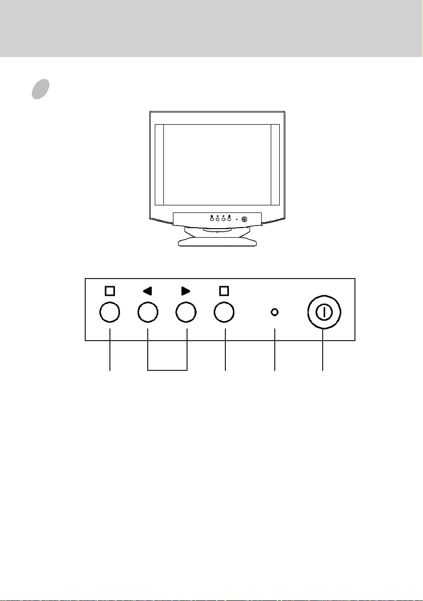
CONTROL PANEL
1 2
E-3
a. Displays menu & exits menu
b. Scrolls through menu to choose an icon for
adjustment /
Adjusts level of selected icon
c. Confirms menu selection
12acb
1. Power LED
2. Power ON/OFF switch
Page 4

E-4
Q
USING THE ON-SCREEN
MENU
1)
Display the On-Screen Menu
Press the button on the front panel to display
the main menu as follows.
1
2
3
4
5
6
7
There is a sub-menu
under every option.
2)
Select a Sub-Menu
Move the cursor by pressing the or button
to select the sub-menu that user's preferred, then
press the button to confirm your selection and
enter sub-menu.
* Either you are in main menu or sub-menu, you
can press the
or sub-menu.
3)
Level Adjustment
Use the or button to adjust value to the
appropriate level. When the button is
pressed, the adjustment level will be stored into
memory.
4)
Quit the On-Screen Menu
When all the adjustments are finished, press
the button to exit the On-Screen Menu.
button to quit the screen menu
OSM INTRODUCTION
1) Screen
If the digital value at right side of bar is flash, it
means that the level is available to adjust the value
now. Otherwise, you can continue to choose any
item which you want to change its level.
Fig. 1
Current Level
2) Image
The moire reduction function is designed to
reduce the dark wavy line Moire patterns on the
screen. You can choose or icon to minimize
the vertical or horizontal moire image by using
or to adjust the image on the screen.
V.MOIRE
100
F1:
UIT
F2:ADJ.
Fig. 2
Page 5

E-5
Ç
3) Color
The color temperature of the white image can be
adjusted.
(1)Use the or button to select 9300°K,
6550°K or the user's preferred color.
(2)If user color is selected, press the button to
display the "COLOR ADJUST" adjustment
screen, then use the , or button again to
adjust the color as desired.
*The GREEN color is fixed and cannot be adjusted.
9300°K COLOR
R
9300°K
G B
R
6550°K
G B
R
USER
G B
F1:QUIT
4) L
anguage
The language of the On-Screen-Menu can be
selected among English, German, Italian, Spanish
and French.
ENGLISH
ENGLISH
DEUTSCH
ITALIANO
ESPAÑOL
FRAN
F1:QUIT
F2:SELECT
Fig. 3
AIS
F2:SAVE
Fig. 4
5) Special Function
a. DEGAUSS
Magnetic field can build up on the CRT
components and cause color impurity. Use
this function to clear the impurities.
b. RECALL
It is possible to restore adjustments to the
original factory settings. If the monitor is
operating in the user defined mode, this
control is invalid.
c. OSM SHOW TIME
User can set the on screen menu display time
between 10 seconds and 35 seconds. The on
screen menu will disappear automatically if
no adjustment action is taken in user's defined
time.
DEGAUSS
DEGAUSS
R
RECAL L
OSM SHOW TIME 35 SEC
F1:QUIT
F2:ADJ.
Fig. 5
6) Display Mode
This item will show the correct display mode ststus.
DISPLAY MODE
H.FREQ. : 31.49KHZ
V.FREQ. : 59.95HZ
H.POL.: -
V.POL. : -
F1:QUIT
Fig. 6
Page 6

E-6
7) OSM Position
Change the OSM appearance position using this
function.
V.POSITION
V.POSITION
H.POSITION
F1:QUIT
F2:ADJ.
Fig.7
TROUBLESHOOTING
If your monitor fails to operate functionally, it may
be possible to correct the problem by making simple
checks as follows:
melborPtsujdA&kcehC
neercsknalB
).eton*(
noitisopyalpsiD
retnec-ffo
llamsootyalpsiD
egralootro
thgirbootyalpsiD
midootro
Refer to the operation instructions for your computer/
video adapter to ensure that you have the correct signal
output source for the monitor. Ensure that the switches
on the video adapter are set correctly for operation
with this monitor.
If the above steps fail to correct the problem contact
your dealer for servicing by qualified service
personnel.
rotcennocro
slortnoc
slortnoc
slortnoc
,hctiwsrewoprotinoM
,elbaclangis,drocrewop
hctiwsrewopCP
tsartnoc&ssenthgirB
&gniretneclacitreV
slortnocesahplatnoziroh
ezislatnoziroh&lacitreV
tsartnoc&ssenthgirB
Please remember that the monitor should be returned
for servicing together with the power cord.
Page 7

E-7
* Note: You can easily distinguish the problem is on
the monitor or on the computer by using the
monitor’s built-in selftest function.
With the monitor power ON, disconnect the
signal cable from monitor. If you see a “NO
SIGNAL” image on the screen, (shown
below) the monitor is function properly, and
the problem is at PC side, or signal cable.
NO SIGNAL
SERVICING
Refer all servicing to qualified service personnel.
Serious shock hazards exist within the covers of
this monitor.
Do not open the covers under any circumstances there are no serviceable parts inside.
SIGNAL CONNECTOR
INFORMATION
1
niPnoitcnuFniPnoitcnuF
1langisdeR9CN
2langisneerG01dnuorglatigiD
3langiseulB11dnuorG
4dnuorG21)B2CDD/1CDD(ADS
5* 31
6nruterdeR41
7
8nrutereulB
neerG
nruter
51)B2CDD(LCS
5
15
latnoziroH
noitazinorhcnyS
noitazinorhcnyslacitreV
)1CDD(KLCV&
*Note: This pin is used for self test detection; at
PC side, this pin has to be connected to
ground.
Page 8

E-8
TECHNICAL SPECIFICATIONS
,lanogaidlausiv"91
eziSneercS
krad
hctiPtoDmm62.0
aerAyalpsiD
)WxH(
sroloCyalpsiDetinifnIthgieWgk12
noituloseR.xaMseniL0021xstoD0061
ytilibitapmoC
noitazinorhcnyS
:.cnySlatnoziroH
:.cnySlacitreV
langiStupnI
elbaClangiSrotcennocbus-Dnip-51OCT59OCTteeM
tupnIrewoP
egatloV
ycneuqerF
zHK59ot03
zH021ot05
golanABGRoediV
etarapeSLTT.cnyS
CAV042ot001
zH06-05
;"81ezisneercselbaweiV
,eralG-itnA,sitatS-itnA
dehcte,noitcelfeR-itnA
rewoP
lacipyt,)mm(262x053noisnemiD
htiwsedomcihpargllA
seicneuqerflatnoziroh
zHK59otzHK03neewteb
gnitaRtnerruCA0.2
noitpmusnoC
)mm(
gnitarepO
erutarepmeT
egarotS
erutarepmeT
ytidimuH
edutitlAtf0007otpU
C53otC5
C56otC04-
%08ot%02
).XAM(W021
084X074X074
)gnisnednoc-non(
*Specifications are subject to change without notice.
PRESET MODES
edoM
1084x0464.13067 867x42010.0657
2004x0274.13078 867x42016.8658
3084x0465.73579 0021x00610.5706
4084x0462.3458014201x08210.0857
5006x0088.6457114201x08211.1958
6006x0086.3558210021x00617.3957
noituloseR
)VxH(
.H
.qerF
)zHK(
.qerF.V
)zH(
edoM
noituloseR
)VxH(
.H
.qerF
)zHK(
.qerF.V
)zH(
 Loading...