

Page 1

IdeaCentreA530All-In-OnePC
ideaideaideaCentreidea
HardwareMaintenanceManual
MachineTypes:10141/F0A8[A530]
Page 2

Page 3

IdeaCentreA530All-In-OnePC
HardwareMaintenanceManual
MachineTypes:10141/F0A8[A530]
Page 4

FirstEdition(June2013)7th
©CopyrightLenovo2013.
LIMITEDANDRESTRICTEDRIGHTSNOTICE:IfdataorsoftwarearedeliveredpursuantaGeneralServices
Administration“GSA”contract,use,reproduction,ordisclosureissubjecttorestrictionssetforthinContractNo.
GS-35F-05925
Page 5

Contents
Chapter1.Aboutthismanual......1
ImportantSafetyInformation..........1
Chapter2.Safetyinformation......3
Generalsafety................3
Electricalsafety...............3
Safetyinspectionguide............5
Handlingelectrostaticdischarge-sensitive
devices..................5
Groundingrequirements............6
Safetynotices................6
Chapter3.Generalinformation.....9
Specications................9
Chapter4.GeneralCheckout.....11
Chapter5.UsingtheSetupUtility...13
StartingtheLenovoBIOSSetupUtilityprogram.13
Viewingandchangingsettings........13
Usingpasswords..............13
Enablingordisablingadevice........15
Selectingastartupdevice..........16
ExitingtheLenovoBIOSSetupUtilityprogram..17
Chapter6.Symptom-to-FRUIndex..19
Harddiskdrivebooterror..........19
PowerSupplyProblems...........19
POSTerrorcodes.............20
Undeterminedproblems...........20
Chapter7.Locatingconnectors,
controlsandcomponents......21
Chapter8.Replacinghardware....29
Generalinformation.............29
Replacingthekeyboardandmouse......30
Replacingthepoweradapter.........30
Removingthebasecover..........32
Replacingtheharddiskdrive.........33
Replacingamemorymodule.........34
Replacingthesystemfan..........35
Replacingtheheat-sink...........36
ReplacingtheCPU.............37
Replacingtheopticaldrive..........39
Replacingthesolidstatedisk.........41
Replacingthemotherboard..........42
Replacingthespeakersystem........45
ReplacingtheTVtunercard.........46
Replacingthebattery............48
Removingthehingefromthechassis......49
Replacingthehingecable..........51
Removingtherearcover...........55
Replacingthescalarboard..........56
Replacingthetouchcontrolboard.......57
Replacingtheconverterboard........58
Replacingthepowerswitchboard.......59
ReplacingtheBluetoothmodule........60
ReplacingtheWi-Ficard...........61
Replacingthecamera............62
Replacingthefrontfunctionboard.......63
ReplacingtheLEDpanel...........64
Chapter9.Generalinformation....67
AdditionalServiceInformation........67
©CopyrightLenovo2013
iii
Page 6

ivIdeaCentreA530All-In-OnePCHardwareMaintenanceManual
Page 7

Chapter1.Aboutthismanual
ThismanualcontainsserviceandreferenceinformationforIdeaCentreA530All-In-Onecomputerslistedon
thecover.ItisintendedonlyfortrainedservicerswhoarefamiliarwithLenovocomputerproducts.
BeforeservicingaLenovoproduct,besuretoreadtheSafetyInformation.
ThedescriptionoftheTV-tunercardinthismanualappliesonlytocomputerswithaTV-tunercardinstalled.
ItdoesnotapplytocomputerswithoutaTV-tunercard.
ImportantSafetyInformation
BesuretoreadallCAUTIONandDANGERsectionsinthismanualbeforefollowinganyoftheinstructions.
VeuillezliretouteslesconsignesdetypeDANGERetA TTENTIONduprésentdocumentavantd’exécuter
lesinstructions.
LesenSieunbedingtalleHinweisevomTyp“ ACHTUNG”oder“VORSICHT”indieserDokumentation,bevor
SieirgendwelcheVorgängedurchführen
LeggereleistruzioniintrodottedaATTENZIONEePERICOLOpresentinelmanualeprimadieseguireuna
qualsiasidelleistruzioni
Certique-sedelertodasasinstruçõesdecuidadoeperigonestemanualantesdeexecutarqualquer
umadasinstruções
Esimportantequeleatodaslasdeclaracionesdeprecauciónydepeligrodeestemanualantesdeseguir
lasinstrucciones.
©CopyrightLenovo2013
1
Page 8

2IdeaCentreA530All-In-OnePCHardwareMaintenanceManual
Page 9

Chapter2.Safetyinformation
Thischaptercontainsthesafetyinformationthatyouneedtobefamiliarwithbeforeservicingacomputer.
Generalsafety
Followtheserulestoensuregeneralsafety:
•Keeptheareasaroundthecomputerclearandcleanduringandaftermaintenance.
•Whenliftinganyheavyobject:
1.Ensureyoucanstandsafelywithoutslipping.
2.Distributetheweightoftheobjectequallyacrossbothfeet.
3.Liftslowly.Nevermovesuddenlyortwistwhenyouattempttolift.
4.Liftbystandingorbypushingupwithyourlegmuscles;thisactionremovesthestrainfromthe
musclesinyourback.
Donotattempttoliftanyobjectsthatweighmorethan16kg(35lbs.)orobjectsthatyouthink
aretooheavyforyou.
•Donotperformanyactionthatwouldcreateahazardforthecustomer,orwouldmakethecomputer
unsafe.
•Beforeyoustartthecomputer,ensurethatotherservicerepresentativesandcustomerpersonnelarenot
inapositionthatwouldcreateahazardforthem.
•Placeremovedcoversandotherpartsinasafeplace,awayfromallpersonnel,whileyouareservicingthe
computer.
•Keepyourtoolcaseawayfromareasthatpeoplemaywalkthroughtoensureno-onetripsoverit.
•Donotwearlooseclothingthatcanbetrappedinthemovingpartsofamachine.Ensurethatyoursleeves
arefastenedorrolledupaboveyourelbows.Ifyourhairislong,tieorfastenitback.
•Inserttheendsofyournecktieorscarfinsideclothingorfastenitwithanonconductiveclip,approximately
8centimeters(3inches)fromtheend.
•Donotwearjewelry,chains,metal-frameeyeglasses,ormetalfastenersforyourclothing.
Remember:Metalobjectsaregoodelectricalconductors.
•Wearsafetyglasseswhenyouare:hammering,drillingsoldering,cuttingwire,attachingsprings,using
solvents,orworkinginanyotherconditionsthatmightbehazardoustoyoureyes.
•Afterservice,reinstallallsafetyshields,guards,labels,andgroundwires.Replaceanysafetydevice
thatiswornordefective.
•Reattachallcoverscorrectlybeforereturningthecomputertothecustomer.
Electricalsafety
CAUTION:
Electricalcurrentfrompower,telephone,andcommunicationcablescanbehazardous.T oavoid
personalinjuryorequipmentdamage,disconnectanyattachedpowercords,telecommunication
cables,networkcables,andmodemcablesbeforeyouopenthecomputercovers,unlessinstructed
otherwiseintheinstallationandcongurationprocedures.
©CopyrightLenovo2013
3
Page 10

Observethefollowingruleswhenworkingonelectricalequipment.
Important:Useonlyapprovedtoolsandtestequipment.Somehandtoolshavehandlescoveredwithasoft
materialthatdoesnotinsulateyouwhenworkingwithliveelectricalcurrents.Manycustomershaverubber
oormatsneartheirequipmentthatcontainsmallconductiveberstodecreaseelectrostaticdischarge.
•Findtheroomemergencypower-off(EPO)switch,disconnectingswitch,orelectricaloutlet.Ifanelectrical
accidentoccurs,youcanthenoperatetheswitchorunplugthepowercordquickly.
•Donotworkaloneunderhazardousconditionsornearequipmentthathashazardousvoltages.
•Disconnectallpowerbefore:
–Performingamechanicalinspection
–Workingnearpowersupplies
–RemovingorinstallingFieldReplaceableUnits(FRUs)
•Beforeyoustarttoworkonthecomputer,unplugthepowercord.Ifyoucannotunplugit,askthe
customertopower-offtheelectricaloutletthatsuppliespowertothemachineandtolocktheelectrical
outletintheoffposition.
•Ifyouneedtoworkonacomputerthathasexposedelectricalcircuits,observethefollowingprecautions:
–Ensurethatanotherperson,familiarwiththepower-offcontrols,isnearyou.
Remember:Anotherpersonmustbetheretoswitchoffthepower,ifnecessary.
–Useonlyonehandwhenworkingwithpowered-onelectricalequipment;keeptheotherhandinyour
pocketorbehindyourback.
Remember:Theremustbeacompletecircuittocauseelectricalshock.Byobservingtheaboverule,
youmaypreventacurrentfrompassingthroughyourbody.
–Whenusingatester,setthecontrolscorrectlyandusetheapprovedprobeleadsandaccessoriesfor
thattester.
–Standonsuitablerubbermats(obtainedlocally,ifnecessary)toinsulateyoufromgroundssuchas
metaloorstripsandmachineframes.
Observethespecialsafetyprecautionswhenyouworkwithveryhighvoltages;theseinstructionsarein
thesafetysectionsofthemaintenanceinformation.Useextremecarewhenmeasuringhighvoltages.
•Regularlyinspectandmaintainyourelectricalhandtoolstoensuretheyaresafetouse.
•Donotusewornorbrokentoolsandtesters.
•Neverassumethatpowerhasbeendisconnectedfromacircuit.First,checkthatithasbeenpoweredoff.
•Alwayslookcarefullyforpossiblehazardsinyourworkarea.Examplesofthesehazardsarewetoors,
non-groundedpowerextensioncables,conditionsthatmaycauseorallowpowersurges,andmissing
safetygrounds.
•Donottouchliveelectricalcircuitswiththereectivesurfaceofaplasticdentalmirror.Thissurfaceis
conductive,andtouchingalivecircuitcancausepersonalinjuryanddamagetothecomputer.
•Donotservicethefollowingpartswiththepoweronwhentheyareremovedfromtheirnormaloperating
positionsinacomputer:
–Powersupplyunits
–Pumps
–Blowersandfans
–Motorgenerators
andsimilarunits.(Thispracticeensurescorrectgroundingoftheunits.)
•Ifanelectricalaccidentoccurs:
–Usecaution;donotbecomeavictimyourself.
4IdeaCentreA530All-In-OnePCHardwareMaintenanceManual
Page 11

–Switchoffpower.
–Sendanotherpersontogetmedicalaid.
Safetyinspectionguide
Theintentofthisinspectionguideistoassistyouinidentifyingpotentialhazardsposedbytheseproducts.
Eachcomputer,asitwasdesignedandbuilt,hadrequiredsafetyitemsinstalledtoprotectusersand
servicepersonnelfrominjury.Thisguideaddressesonlythoseitems.However,goodjudgmentshouldbe
usedtoidentifypotentialsafetyhazardsduetoattachmentoffeaturesoroptionsnotcoveredbythis
inspectionguide.
Ifanyhazardsarepresent,youmustdeterminehowserioustheapparenthazardcouldbeandwhetheryou
cancontinuewithoutrstresolvingtheproblem.
Considerthefollowingitemsandthesafetyhazardstheypresent:
•Electricalhazards,especiallyprimarypower(primaryvoltageontheframecancauseseriousorfatal
electricalshock).
•Explosivehazards,suchasadamagedCRTfaceorbulgingcapacitor
•Mechanicalhazards,suchaslooseormissinghardware
Theguideconsistsofaseriesofstepspresentedasachecklist.Beginthecheckswiththepoweroff,and
thepowercorddisconnected.
Checklist:
1.Checkexteriorcoversfordamage(loose,broken,orsharpedges).
2.Power-offthecomputer.Disconnectthepowercord.
3.Checkthepowercordfor:
a.Athird-wiregroundconnectoringoodcondition.Useametertomeasurethird-wireground
continuityfor0.1ohmorlessbetweentheexternalgroundpinandframeground.
b.Thepowercordshouldbetheappropriatetypeasspeciedinthepartslistings.
c.Insulationmustnotbefrayedorworn.
4.Removethecover.
5.Checkforanyobviousalterations.Usegoodjudgmentastothesafetyofanyalterations.
6.Checkinsidetheunitforanyobvioushazards,suchasmetallings,contamination,waterorother
liquids,orsignsofreorsmokedamage.
7.Checkforworn,frayed,orpinchedcables.
8.Checkthatthepower-supplycoverfasteners(screwsorrivets)havenotbeenremovedortamperedwith.
Handlingelectrostaticdischarge-sensitivedevices
Anycomputerpartcontainingtransistorsorintegratedcircuits(ICs)shouldbeconsideredsensitiveto
electrostaticdischarge(ESD).ESDdamagecanoccurwhenthereisadifferenceinchargebetweenobjects.
ProtectagainstESDdamagebyequalizingthechargesothatthecomputer,thepart,theworkmat,andthe
personhandlingthepartareallatthesamecharge.
Notes:
1.Useproduct-specicESDprocedureswhentheyexceedtherequirementsnotedhere.
2.MakesurethattheESDprotectivedevicesyouusehavebeencertied(ISO9000)asfullyeffective.
WhenhandlingESD-sensitiveparts:
Chapter2.Safetyinformation5
Page 12

•Keepthepartsinprotectivepackagesuntiltheyareinsertedintotheproduct.
•Avoidcontactwithotherpeoplewhilehandlingthepart.
•Wearagroundedwriststrapagainstyourskintoeliminatestaticonyourbody.
•Preventthepartfromtouchingyourclothing.Mostclothingisinsulativeandretainsachargeevenwhen
youarewearingawriststrap.
•Usetheblacksideofagroundedworkmattoprovideastatic-freeworksurface.Thematisespecially
usefulwhenhandlingESD-sensitivedevices.
•Selectagroundingsystem,suchasthoselistedbelow,toprovideprotectionthatmeetsthespecic
servicerequirement.
Note:TheuseofagroundingsystemisdesirablebutnotrequiredtoprotectagainstESDdamage.
–AttachtheESDgroundcliptoanyframeground,groundbraid,orgreen-wireground.
–UseanESDcommongroundorreferencepointwhenworkingonadouble-insulatedor
battery-operatedsystem.Y oucanusecoaxorconnector-outsideshellsonthesesystems.
–Usetheroundground-prongoftheACplugonAC-operatedcomputers.
Groundingrequirements
Electricalgroundingofthecomputerisrequiredforoperatorsafetyandcorrectsystemfunction.Proper
groundingoftheelectricaloutletcanbeveriedbyacertiedelectrician.
Safetynotices
TheCAUTIONandDANGERsafetynoticesinthissectionareprovidedinthelanguageofEnglish.
DANGER
Electricalcurrentfrompower,telephoneandcommunicationcablesishazardous.
Toavoidashockhazard:
•Donotconnectordisconnectanycablesorperforminstallation,maintenance,orreconguration
ofthisproductduringanelectricalstorm.
•Connectallpowercordstoaproperlywiredandgroundedelectricaloutlet.
•Connectanyequipmentthatwillbeattachedtothisproducttoaproperlywiredoutlet.
•Whenpossible,useonehandonlytoconnectordisconnectsignalcables.
•Neverturnonanyequipmentwhenthereisevidenceofre,water,orstructuraldamage.
•Disconnecttheattachedpowercords,telecommunicationscables,networkcables,andmodem
cablesbeforeyouopenthedevicecovers,unlessinstructedotherwiseintheinstallationand
congurationprocedures.
•Connectanddisconnectcablesasdescribedinthefollowingtablewheninstalling,moving,or
openingcoversonthisproductorattacheddevices.
6IdeaCentreA530All-In-OnePCHardwareMaintenanceManual
Page 13
ToConnect
1.TurneverythingOFF .
2.First,attachallcablestodevices.
3.Attachsignalcablestoconnectors.
4.Attachpowercordstooutlet.
5.TurndeviceON.
ToDisconnect
1.TurneverythingOFF .
2.First,removepowercordsfromoutlets.
3.Removesignalcablesfromconnectors.
4.Removeallcablesfromdevices.
CAUTION:
Whenreplacingthelithiumbattery,useonlyPartNumber45C1566oranequivalenttypebattery
recommendedbythemanufacturer.Ifyoursystemhasamodulecontainingalithiumbattery,replace
itonlywiththesamemoduletypemadebythesamemanufacturer .Thebatterycontainslithiumand
canexplodeifnotproperlyused,handled,ordisposedof.
Donot:
•Throwintoorimmerseinwater
•Heattomorethan100°C(212°F)
•Repairordisassemble
Disposeofthebatteryasrequiredbylocalordinancesorregulations.
CAUTION:
Whenlaserproducts(suchasCD-ROMs,DVD-ROMdrives,beropticdevices,ortransmitters)are
installed,notethefollowing:
•Donotremovethecovers.Removingthecoversofthelaserproductcouldresultinexposureto
hazardouslaserradiation.Therearenoserviceablepartsinsidethedevice.
•Useofcontrolsoradjustmentsorperformanceofproceduresotherthanthosespeciedherein
mightresultinhazardousradiationexposure.
DANGER
SomelaserproductscontainanembeddedClass3AorClass3Blaserdiode.Notethefollowing:
Thesediodesemitradiationwhenopen.Donotstareintothebeam,donotviewdirectlywith
opticalinstruments,andavoiddirectexposuretothebeam.
Chapter2.Safetyinformation7
Page 14
≥18kg(37lbs)≥32kg(70.5lbs)≥55kg(121.2lbs)
1
2
CAUTION:
Usesafepracticeswhenlifting.
CAUTION:
Thepowercontrolbuttononthedeviceandthepowerswitchonthepowersupplydonotturnoff
theelectricalcurrentsuppliedtothedevice.Thedevicealsomighthavemorethanonepower
cord.Toremoveallelectricalcurrentfromthedevice,ensurethatallpowercordsaredisconnected
fromthepowersource.
CAUTION:
Donotplaceanyobjectweighingmorethan82kg(180lbs.)ontopofrack-mounteddevices.
8IdeaCentreA530All-In-OnePCHardwareMaintenanceManual
Page 15

Chapter3.Generalinformation
Thischapterprovidesgeneralinformationthatappliestoallcomputermodelscoveredbythismanual.
Specications
Thissectionliststhephysicalspecicationsforyourcomputer.
Thissectionliststhephysicalspecicationsforyourcomputer.
TypeIdeaCentreA530
Thissectionliststhephysicalspecications.
Environment
Airtemperature:
Operating:10°to35°C
Transit:-20°to55°C
Humidity:
Operating:35%to80%
Transit:20%to90%(40°C)
Altitude:86KPato106KPa
Electricalinput:
Inputvoltage:90V-264V(AC)
Inputfrequency:47Hz-63Hz
©CopyrightLenovo2013
9
Page 16

10IdeaCentreA530All-In-OnePCHardwareMaintenanceManual
Page 17

Chapter4.GeneralCheckout
Attention:Thedrivesinthecomputeryouareservicingmighthavebeenrearrangedorthedrivestartup
sequencemayhavebeenchanged.Beextremelycarefulduringwriteoperationssuchascopying,saving,or
formatting.Dataorprogramscanbeoverwrittenifyouselectanincorrectdrive.
Generalerrormessagesappearifaproblemorconictisfoundbyanapplication,theoperatingsystem,or
both.Foranexplanationofthesemessages,refertotheinformationsuppliedwiththatsoftwarepackage.
Usethefollowingproceduretohelpdeterminethecauseoftheproblem:
1.Power-offthecomputerandallexternaldevices.
2.Checkallcablesandpowercords.
3.Setalldisplaycontrolstothemiddleposition.
4.Power-onallexternaldevices.
5.Power-onthecomputer.
•Lookfordisplayederrorcodes.
•Lookforreadableinstructionsoramainmenuonthedisplay.
Ifyoudidnotreceivethecorrectresponse,proceedtostep6.
Ifyoudidreceivethecorrectresponse,proceedtostep7.
6.Ifoneofthefollowinghappens,followtheinstructiongiven:
•IfthecomputerdisplaysaPOSTerror,goto“POSTerrorcodes” .
•Ifthecomputerhangsandnoerrorisdisplayed,continueatstep7.
7.Iftheteststopsandyoucannotcontinue,replacethelastdevicetested.
©CopyrightLenovo2013
11
Page 18

12IdeaCentreA530All-In-OnePCHardwareMaintenanceManual
Page 19

Chapter5.UsingtheSetupUtility
TheSetupUtilityprogramisusedtoviewandchangethecongurationsettingsofyourcomputer,regardless
ofwhichoperatingsystemyouareusing.However,theoperatingsystemsettingsmightoverrideanysimilar
settingsintheSetupUtilityprogram.
StartingtheLenovoBIOSSetupUtilityprogram
TostarttheLenovoBIOSSetupUtilityprogram,dothefollowing:
1.Ifyourcomputerisalreadyonwhenyoustartthisprocedure,shutdowntheoperatingsystemand
turnoffthecomputer.
2.PressandholdtheF1keythenturnonthecomputer.WhentheLenovoBIOSSetupUtilityprogramis
displayed,releasetheF1key.
Note:IfaPower-OnPasswordoranAdministratorPasswordhasbeenset,theSetupUtilityprogrammenu
willnotbedisplayeduntilyoutypeyourpassword.Formoreinformation,see“Usingpasswords.”
Viewingandchangingsettings
SystemcongurationoptionsarelistedintheLenovoBIOSSetupUtilityprogrammenu.T ovieworchange
settings,see“StartingtheSetupUtilityprogram. ”
YoumustusethekeyboardwhenusingtheLenovoBIOSSetupUtilitymenu.Thekeysusedtoperform
varioustasksaredisplayedonthebottomofeachscreen.
Usingpasswords
YoucanusetheLenovoBIOSSetupUtilityprogramtosetpasswordstopreventunauthorizedpersons
fromgainingaccesstoyourcomputeranddata.See“StartingtheSetupUtilityprogram.”Thefollowing
typesofpasswordsareavailable:
•AdministratorPassword
•Power-OnPassword
Youdonothavetosetanypasswordstouseyourcomputer.However,ifyoudecidetosetpasswords,read
thefollowingsections.
Passwordconsiderations
Apasswordcanbeanycombinationoflettersandnumbersupto16characters(a-zand0-9).Forsecurity
reasons,itisagoodideatouseastrongpasswordthatcannotbeeasilycompromised.Wesuggestthat
passwordsshouldfollowtheserules:
•Forastrongpassword,use7-16charactersandamixoflettersandnumbers.
•Donotuseyournameoryourusername.
•Donotuseacommonwordoracommonname.
•Usesomethingsignicantlydifferentfromyourpreviouspassword.
Attention:AdministratorandPower-Onpasswordsarenotcasesensitive.
©CopyrightLenovo2013
13
Page 20

AdministratorPassword
SettinganAdministratorPassworddetersunauthorizedpersonsfromchangingcongurationsettings.Y ou
mightwanttosetanAdministratorPasswordifyouareresponsibleformaintainingthesettingsofseveral
computers.
AfteryousetanAdministratorPassword,apasswordpromptisdisplayedeverytimeyouaccesstheLenovo
BIOSSetupUtilityprogram.
IfboththeAdministratorandPower-OnPasswordareset,youcantypeeitherpassword.However,youmust
useyourAdministratorPasswordtochangeanycongurationsettings.
Setting,changing,ordeletinganAdministratorPassword
TosetanAdministratorPassword,dothefollowing:
Note:Apasswordcanbeanycombinationoflettersandnumbersupto16characters(a-zand0-9).For
moreinformation,see“Passwordconsiderations”onpage13.
1.StarttheLenovoBIOSSetupUtilityprogram(see“StartingtheLenovoBIOSSetupUtilityprogram”on
page13).
2.FromtheSecuritymenu,selectSetAdministratorPasswordandpresstheEnterkey.
3.Thepassworddialogboxwillbedisplayed.T ypethepasswordthenpresstheEnterkey.
4.Re-typethepasswordtoconrm,thenpresstheEnterkey.Ifyoutypedthepasswordcorrectly,
thepasswordwillbeinstalled.
TochangeanAdministratorPassword,dothefollowing:
1.StarttheLenovoBIOSSetupUtilityprogram(see“StartingtheLenovoBIOSSetupUtilityprogram”on
page13).
2.FromtheSecuritymenu,selectSetAdministratorPasswordandpresstheEnterkey.
3.Thepassworddialogboxwillbedisplayed.TypethecurrentpasswordthenpresstheEnterkey.
4.T ypethenewpassword,thenpresstheEnterkey.Re-typethenewpasswordtoconrmit.Ifyoutyped
thenewpasswordcorrectly,thenewpasswordwillbeinstalled.ASetupNoticewillbedisplayed
conrmingthatyourchangeshavebeensaved.
5.ReturntotheLenovoBIOSSetupUtilityprogrammenuandselecttheExitoption.
6.SelectSaveChangesandExitfromthemenu.
TodeleteapreviouslysetAdministratorPassword,dothefollowing:
1.StarttheLenovoBIOSSetupUtilityprogram(see“StartingtheLenovoBIOSSetupUtilityprogram”on
page13).
2.FromtheSecuritymenu,selectSetAdministratorPasswordandpresstheEnterkey.
3.Thepassworddialogboxwillbedisplayed.TypethecurrentpasswordandpresstheEnterkey.
4.Leaveeachnewpasswordlineitemblank,thenpresstheEnterkey.ASetupNoticewillbedisplayed
conrmingthatyourchangeshavebeensaved.
5.ReturntotheLenovoBIOSSetupUtilityprogrammenuandselecttheExitoption.
6.SelectSaveChangesandExitfromthemenu.
Power-OnPassword
14IdeaCentreA530All-In-OnePCHardwareMaintenanceManual
Page 21

WhenaPower-OnPasswordisset,youcannotstarttheLenovoBIOSSetupUtilityprogramuntilavalid
passwordistypedfromthekeyboard.
Setting,changing,ordeletingaPower-OnPassword
Note:Apasswordcanbeanycombinationoflettersandnumbersupto16characters(a-zand0-9).
TosetaPower-OnPassword,dothefollowing:
1.StarttheLenovoBIOSSetupUtilityprogram(see”StartingtheLenovoBIOSSetupUtilityprogram”on
page13).
2.FromtheSecuritymenu,selectSetPower-OnPasswordandpresstheEnterkey.
3.Thepassworddialogboxwillbedisplayed.T ypethepassword,thenpresstheEnterkey.
4.Re-typethepasswordtoconrmit.Ifyoutypedthepasswordcorrectly,thepasswordwillbeinstalled.
5.ReturntotheLenovoBIOSSetupUtilityprogrammenuandselecttheExitoption.
6.SelectSaveChangesandExitfromthemenu.
TochangeaPower-OnPassword,dothefollowing:
1.StarttheLenovoBIOSSetupUtilityprogram(see”StartingtheLenovoBIOSSetupUtilityprogram”on
page13).
2.FromtheSecuritymenu,selectSetPower-OnPasswordandpresstheEnterkey.
3.Thepassworddialogboxwillbedisplayed.TypethecurrentpasswordthenpresstheEnterkey.
4.T ypethenewpassword,thenpresstheEnterkey.Re-typethenewpasswordtoconrmit.Ifyoutyped
thenewpasswordcorrectly,thenewpasswordwillbeinstalled.ASetupNoticewillbedisplayed
conrmingthatyourchangeshavebeensaved.
5.ReturntotheLenovoBIOSSetupUtilityprogrammenuandselecttheExitoption.
6.SelectSaveChangesandExitfromthemenu.
TodeleteapreviouslysetPower-OnPassword,dothefollowing:
1.StarttheLenovoBIOSSetupUtilityprogram(see”StartingtheLenovoBIOSSetupUtilityprogram”on
page13).
2.FromtheSecuritymenu,selectSetPower-OnPasswordandpresstheEnterkey.
3.Thepassworddialogboxwillbedisplayed.TypethecurrentpasswordandpresstheEnterkey.
4.Leaveeachnewpasswordlineitemblank,thenpressEnterkey.ASetupNoticewillbedisplayed
conrmingthatyourchangeshavebeensaved.
5.ReturntotheLenovoBIOSSetupUtilityprogrammenuandselecttheExitoption.
6.SelectSaveChangesandExitfromthemenu.
Enablingordisablingadevice
TheDevicesoptionsisusedtoenableordisableuseraccesstothefollowing:
USBFunctionsSelectwhethertoenableordisableUSB(UniversalSerial
Bus)functions.Ifthefunctionsaredisabled,noUSB
devicescanbeused.
SATAMode
WhenthisfeatureissettoDisabled,alldevices
connectedtotheSATAconnectors(e.g.harddiskdrives
ortheopticaldiskdrive)aredisabledandcannotbe
accessed.
Chapter5.UsingtheSetupUtility15
Page 22

OnboardAudioControllerSelectwhethertoenableordisabletheOnboard
AudioController.WhenthisfeatureissettoDisabled
alldevicesconnectedtotheaudioconnectors(e.g.
headphonesoramicrophone)aredisabledandcannot
beused.
OnboardEthernetControllerorLANBootAgentSelectwhethertoenableordisabletheOnboardEthernet
Controller,orselectwhethertoenableordisableload
onboardPXE(PrebootExecutionEnvironment).
Toenableordisableadevice,dothefollowing:
1.StarttheSetupUtilityprogram(see“StartingtheSetupUtilityprogram”onpage13).
2.FromtheSetupUtilityprogrammenu,selectDevices.
3.Selectanoptionasfollows:
SelectUSBSetup,presstheEnterkey,thenselectUSBFunctions.
SelectA T ADeviceSetup,presstheEnterkey,thenselectSATAMode.
SelectAudioSetup,presstheEnterkey,thenselectOnboardAudioController.
SelectNetworkSetup,presstheEnterkey,thenselectOnboardEthernetSupportorLANBoot
Agent.
4.SelectDisabledorEnabledandpresstheEnterkey.
5.ReturntotheLenovoBIOSSetupUtilityprogrammenuandselecttheExitoption.
6.SelectSaveChangesandExitfromthemenu.
Notes:
a.Ifyoudonotwanttosavethesettings,selectDiscardChangesandExitfromthemenu.
b.SelectIDE/AHCIMode:DevicedriversupportisrequiredforAHCI.Dependingonhowtheharddisk
imagewasinstalled,changingthissettingmaypreventthesystemfrombooting.
Selectingastartupdevice
IfyourcomputerdoesnotbootfromadevicesuchastheCD/DVD-ROMdrivediskorharddiskasexpected,
followoneoftheproceduresbelow.
Selectingatemporarystartupdevice
Usethisproceduretostartupfromanybootdevice.
Note:NotallCDs,DVDsorharddiskdrivesarebootable.
1.T urnoffyourcomputer.
2.PressandholdtheF12keythenturnonthecomputer.WhentheStartupDeviceMenuappears,
releasetheF12key.
Note:IftheStartupDeviceMenudoesnotdisplayusingthesesteps,repeatedlypressandreleasethe
F12keyratherthankeepingitpressedwhenturningonthecomputer.
3.Use↑and↓arrowstoselectthedesiredstartupdevicefromtheStartupDeviceMenuandpress
theEnterkeytobegin.
Note:SelectingastartupdevicefromtheStartupDeviceMenudoesnotpermanentlychangethe
startupsequence.
Selectingorchangingthestartupdevicesequence
16IdeaCentreA530All-In-OnePCHardwareMaintenanceManual
Page 23

Tovieworpermanentlychangetheconguredstartupdevicesequence,dothefollowing:
1.StarttheLenovoBIOSSetupUtilityprogram(see“StartingtheLenovoBIOSSetupUtilityprogram”on
page13).
2.FromtheLenovoBIOSSetupUtilityprogrammainmenu,selecttheStartupoption.
3.PresstheEnterkey,andselectthedevicesforthePrimaryBootSequence.Readtheinformation
displayedontherightsideofthescreen.
4.Use↑and↓arrowstoselectadevice.Usethe<+>or<->keystomoveadeviceupordown.Usethe
<×>keytoexcludethedevicefromorincludethedeviceinthebootsequence.
5.ReturntotheLenovoBIOSSetupUtilityprogrammenuandselecttheExitoption.
6.SelectSaveChangesandExitfromthemenu.
Notes:
a.Ifyoudonotwanttosavethesettings,selectDiscardChangesandExitfromthemenu.
b.Ifyouhavechangedthesesettingsandwanttoreturntothedefaultsettings,selectLoadOptimal
Defaultsfromthemenu.
ExitingtheLenovoBIOSSetupUtilityprogram
Afteryounishviewingorchangingsettings,presstheEsckeytoreturntotheLenovoBIOSSetupUtility
programmainmenu.Y oumighthavetopresstheEsckeyseveraltimes.Dooneofthefollowing:
•Ifyouwanttosavethenewsettings,selectSaveChangesandExitfromthemenu.WhentheSave
&resetwindowshows,selecttheY esbutton,andthenpresstheEnterkeytoexittheLenovoBIOS
SetupUtilityprogram.
•Ifyoudonotwanttosavethesettings,selectDiscardChangesandExitfromthemenu.Whenthe
ResetWithoutSavingwindowshows,selecttheYesbutton,andthenpresstheEnterkeytoexitthe
LenovoBIOSSetupUtilityprogram.
Chapter5.UsingtheSetupUtility17
Page 24

18IdeaCentreA530All-In-OnePCHardwareMaintenanceManual
Page 25

Chapter6.Symptom-to-FRUIndex
TheSymptom-to-FRUindexlistserrorsymptomsandpossiblecauses.Themostlikelycauseislistedrst.
AlwaysbeginwithChapter4,“GeneralCheckout,”onpage11.Thisindexcanalsobeusedtohelpyou
decidewhichFRUstohaveavailablewhenservicingacomputer.Ifyouareunabletocorrecttheproblem
usingthisindex,goto“Undeterminedproblems”onpage20.
Notes:
•Ifyouhavebothanerrormessageandanincorrectaudioresponse,diagnosetheerrormessagerst.
•Ifyoucannotrunthediagnostictestsoryougetadiagnosticerrorcodewhenrunningatestbutdid
receiveaPOSTerrormessage,diagnosethePOSTerrormessagerst.
•Ifyoudidnotreceiveanyerrormessagelookforadescriptionofyourerrorsymptomsintherstpartof
thisindex.
Harddiskdrivebooterror
Aharddiskdrivebooterrorcanhavethefollowingcauses.
Error
Thestartupdriveisnotincludedinthebootsequence
conguration.
Nooperatingsystemisinstalledonthebootdrive.Installanoperatingsystemonthebootdrive.
Thebootsectoronthestartupdriveiscorrupted.
Thedriveisdefective.
FRU/Action
Checkthecongurationandensurethestartupdriveis
inthebootsequence.
Thedrivemustbeformatted.Dothefollowing:
1.Attempttobackupthedataonthefailingharddisk
drive.
2.Usetheoperatingsystemtoformattheharddisk
drive.
Replacetheharddiskdrive.
PowerSupplyProblems
Followtheseproceduresifyoususpectthereisapowersupplyproblem.
Check/VerifyFRU/Action
Checkthatthefollowingareproperlyinstalled:
•PowerCord
•On/OffSwitchconnector
•SystemBoardPowerSupplyconnectors
•Microprocessorconnections
Checkthepowercord.PowerCord
Checkthepower-onswitch.Power-onSwitch
Reseatconnectors
©CopyrightLenovo2013
19
Page 26

POSTerrorcodes
Eachtimeyouturnthecomputeron,itperformsaseriesofteststocheckthatthesystemisoperating
correctlyandthatcertainoptionsareset.ThisseriesoftestsiscalledthePower-OnSelf-Test,orPOST.
POSTdoesthefollowing:
•Checkssomebasicmotherboardoperations
•Checksthatthememoryisworkingcorrectly
•Startsvideooperations
•Veriesthatthebootdriveisworking
POSTErrorMessageDescription/Action
Keyboarderror
RebootandSelectproperBootdeviceorInsertBoot
MediainselectedBootdevice
Cannotinitializethekeyboard.Makesurethekeyboard
isproperlyconnectedtothecomputerandthatnokeys
areheldpressedduringPOST .Topurposelycongure
thecomputerwithoutakeyboard,selectKeyboardless
operationinStartupandsettheoptiontoEnabled.The
BIOSthenignoresthemissingkeyboardduringPOST.
TheBIOSwasunabletondasuitablebootdevice.Make
surethebootdriveisproperlyconnectedtothecomputer.
Makesureyouhavebootablemediainthebootdevice.
Undeterminedproblems
1.Power-offthecomputer.
2.Removeordisconnectthefollowingcomponents(ifconnectedorinstalled)oneatatime.
a.Externaldevices(modem,printer,ormouse)
b.Extendedvideomemory
c.ExternalCache
d.ExternalCacheRAM
e.Harddiskdrive
f.Diskdrive
3.Power-onthecomputertore-testthesystem.
4.Repeatsteps1through3untilyoundthefailingdeviceorcomponent.
Ifalldevicesandcomponentshavebeenremovedandtheproblemcontinues,replacethesystemboard.
20IdeaCentreA530All-In-OnePCHardwareMaintenanceManual
Page 27

Chapter7.Locatingconnectors,controlsandcomponents
1 2 3
4 8765 9
10 11 1312 14 15
16
17
Thissectionprovidesillustrationstohelplocatethevariousconnectors,controlsandcomponentsofthe
computer.
Frontview
Thefollowingillustrationshowsthelocationofcontrolsandcomponentsonthefrontofthecomputer.
Attention:Becarefulnottoblockanyairventsonthecomputer.Blockedairventscancauseoverheating.
1.Built-inmicrophone
2.Built-incamera11.NovoVisionbutton
3.Built-inmicrophone(selectedmodelsonly)
4.Powerindicator13.Volumeup
5.Harddiskdriveindicator14.Brightnessdown
6.Bluetoothstatusindicator15.Brightnessup
7.Wi-Fistatusindicator16.Built-inspeakers
8.HDMI-inindicator17.Memorycardreader
9.MonitorOn/Off
©CopyrightLenovo2013
10.PCmode/HDMI-in/AV-inswitch
12.Volumedown
21
Page 28
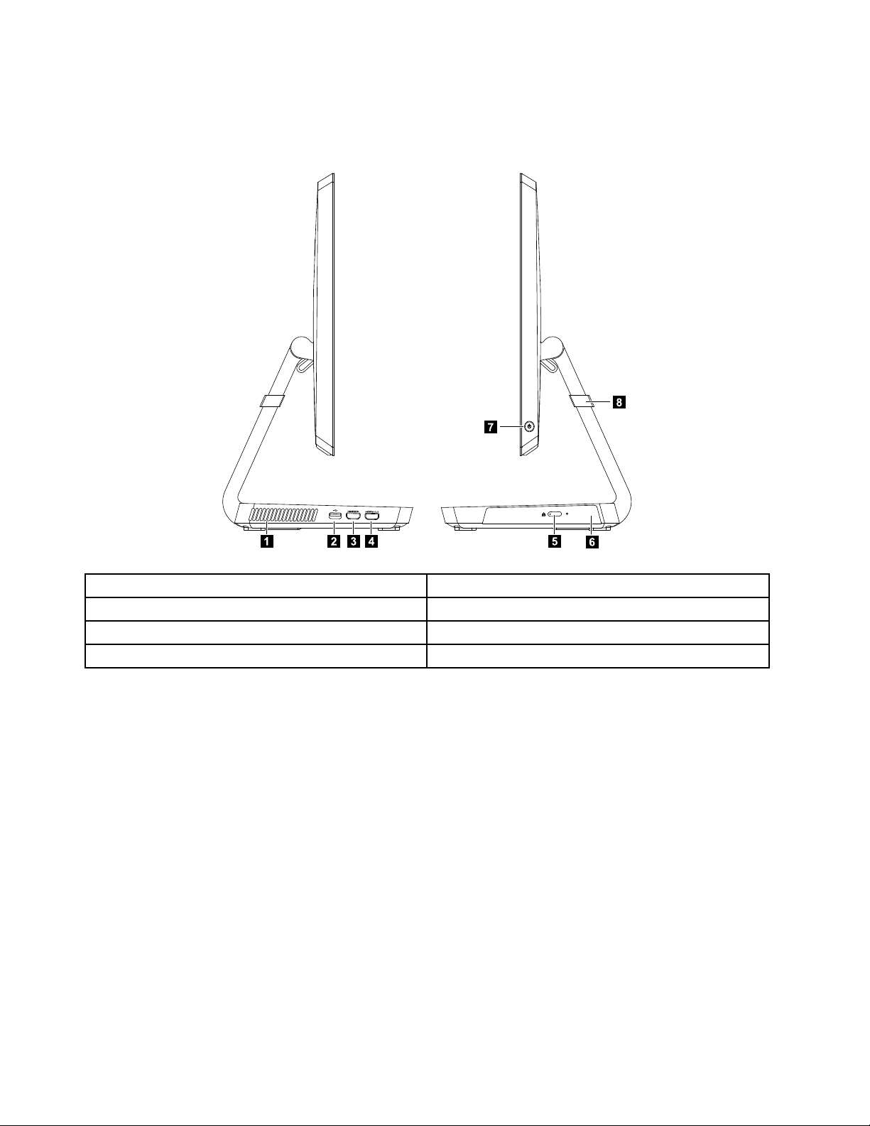
Leftandrightview
2 3 4 5
6
7
1
8
Thefollowingillustrationshowsthelocationofconnectors,controlsandcomponentsontheleftandright
sideofthecomputer.
1.Airvents
5.Opticaldriveejectbutton
2.USB3.0connector6.Opticaldrive
3.HDMI-inconnector(selectedmodelsonly)
7.Powerbutton
4.HDMI-outconnector8.Anti-scratchprotector
22IdeaCentreA530All-In-OnePCHardwareMaintenanceManual
Page 29
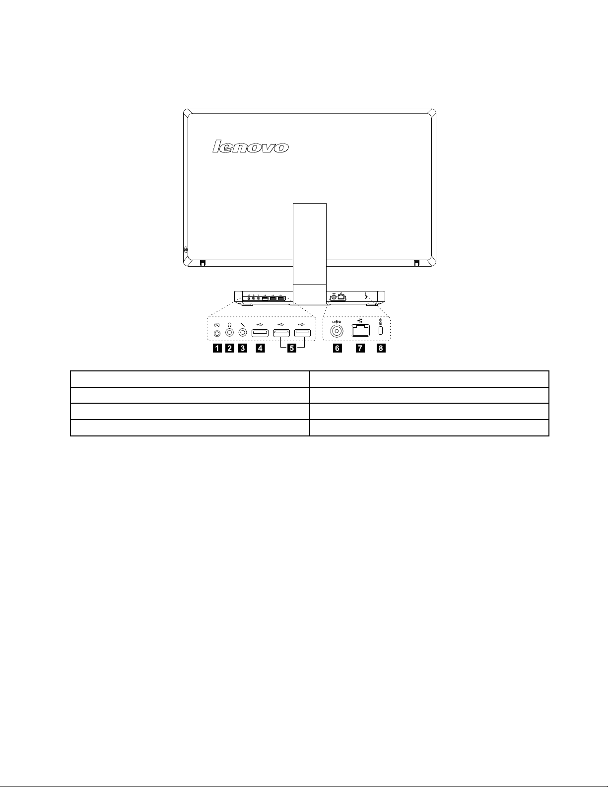
Rearview
1 2 3 8764 5
Thefollowingillustrationshowsthelocationofconnectorsandcomponentsontherearofthecomputer.
1.TV- T unerconnector(selectedmodelsonly)5.USB2.0connectors(2)
2.Headphoneconnector6.Powerconnector
3.Microphoneconnector
4.USB3.0connector8.Securitycableslot
7.Ethernetconnector(RJ45)
Chapter7.Locatingconnectors,controlsandcomponents23
Page 30
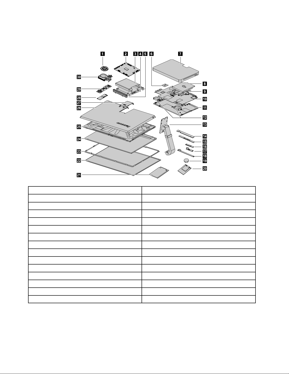
Hardwarecomponents
4 5 6 7
9
10
11
12
13
14
15
16
17
18
19
20
8
22
23
24
25
26
27
28
29
30
21
Thefollowingillustrationshowsthecomponentsthatmakeupyourcomputer.
1.Systemfan
2.Scalarboard
3.Harddiskdrivebracket
16.Bluetoothmodule
17.Powerswitchboard
18.Frontfunctionboard
4.Harddiskdrive19.Battery
5.Harddiskdriverubbers
6.CPU
7.Basecover
8.Opticaldrive
9.Opticaldrivebracket
10.Motherboard
11.Chassis
12.Speakers
13.Hinge28.T ouchcontrolboard
14.Camera29.Converter
15.Wi-Ficard30.Heat-sink
20.Solidstatedisk
21.TV- T unercard
22.Glass
23.Panelframe
24.LEDpanel
25.Middleframe
26.Rearcover
27.Rearcoverdeco
24IdeaCentreA530All-In-OnePCHardwareMaintenanceManual
Page 31

Identifyingpartsonthemotherboard
Themotherboard(sometimescalledtheplanarorsystemboard)isthemaincircuitboardinyourcomputer.
Itprovidesbasiccomputingfunctionsandsupportsavarietyofdevicesthatarefactory-installedorthat
canbeinstalledlater.Thefollowingillustrationshowsthelocationofconnectorsandcomponentson
thefrontofthemotherboard.
1.HDMI-outconnector12.Headphoneconnector
2.HDMI-inconnector13.TVjack
3.USB3.0connector14.Scalarheadphoneinputconnector(Functionalwhen
switchedtoHDMI-inmode)
4.Ethernetconnector(RJ45)15.Speakerconnector
5.Powerconnector
6.Systemfanconnector17.Cardreader
7.DVI/HDMIcableconnector18.Solidstatediskconnector
8.Scalarcableconnector
9.USB2.0connectors(2)
10.USB3.0connector21.CPUsocket
11.Microphoneconnector
16.Opticaldriveconnector
19.Harddiskdriveconnector
20.Memoryslots
Chapter7.Locatingconnectors,controlsandcomponents25
Page 32

Thefollowingillustrationshowsthelocationofconnectorsandcomponentsonthebackofthemotherboard.
22
23
22.TV-T unercardconnector23.Battery
26IdeaCentreA530All-In-OnePCHardwareMaintenanceManual
Page 33

IdentifyingpartsonthebackoftheLEDpanel
1 2 3
4
5678
ThefollowingillustrationshowsthelocationofcomponentsandcontrolsonthebackofLEDpanel.
1.Bluetoothmodule
2.Wi-Ficard
3.Camera
4.Frontfunctionboard
5.Scalarboard
6.Converterboard
7.T ouchcontrolboard
8.Powerswitchboard
Chapter7.Locatingconnectors,controlsandcomponents27
Page 34

28IdeaCentreA530All-In-OnePCHardwareMaintenanceManual
Page 35

Chapter8.Replacinghardware
Attention:Donotremovethecomputercoverorattemptanyrepairbeforereadingthe“Importantsafetyinformation”
intheSafetyandWarrantyGuidethatwasincludedwithyourcomputer.ToobtaincopiesoftheSafetyandWarranty
Guide,gototheSupportWebsiteat:http://support.lenovo.com.
Note:UseonlypartsprovidedbyLenovo.
Generalinformation
Pre-disassemblyinstructions
Beforestartingthedisassemblyprocedure,makesurethatyoudothefollowing:
1.T urnoffthepowertothesystemandallperipherals.
2.Unplugallpowerandsignalcablesfromthecomputer.
3.Placethesystemonaat,stablesurface.
©CopyrightLenovo2013
29
Page 36

Replacingthekeyboardandmouse
Toreplacethekeyboardandmouse:
Step1.Removeanymedia(disks,CDs,DVDsormemorycards)fromthedrives,shutdowntheoperating
system,andturnoffthecomputerandallattacheddevices.
Step2.Unplugallpowercordsfromelectricaloutlets.
Step3.Disconnectallcablesattachedtothecomputer.Thisincludespowercords,input/output(I/O)
cables,andanyothercablesthatareconnectedtothecomputer.Referto“Leftandrightview”
and“Rearview”forhelpwithlocatingthevariousconnectors.
Note:Y ourkeyboardwillbeconnectedtoaUSBconnectorononesideorattherearofthe
computer.
Step4.Disconnectthedefectivekeyboardcablefromthecomputerandconnectthenewkeyboardcable
tothesameconnector.
Note:Themousecanbereplacedusingthesamemethod.
Replacingthepoweradapter
Toreplacethepoweradapter:
Step1.Removeanymedia(disks,CDs,DVDs,ormemorycards)fromthedrives,shutdowntheoperating
system,andturnoffthecomputerandallattacheddevices.
Step2.Locatetheconnectorforthepowercord.Referto“Rearview”.
30IdeaCentreA530All-In-OnePCHardwareMaintenanceManual
Page 37

Step3.Disconnectthefailingpoweradapterfromthecomputer.
Step4.Toinstallthenewpoweradapter:
a.Connectthenewpoweradaptertothesameconnector.
Chapter8.Replacinghardware31
Page 38

Removingthebasecover
Note:T urnoffthecomputerandwait3to5minutestoletitcooldownbeforeremovingthebasecover.
Note:Itmaybehelpfultoplacethecomputerface-downonasoftatsurfaceforthisprocedure.Lenovo
recommendsthatyouuseablanket,towel,orothersoftclothtoprotectthecomputerscreenfromscratches
orotherdamage.
Toremovethebasecover:
Step1.Removeanymedia(disks,CDs,DVDs,ormemorycards)fromthedrives,shutdowntheoperating
system,andturnoffthecomputerandallattacheddevices.
Step2.Unplugallpowercordsfromelectricaloutlets.
Step3.Disconnectallcablesattachedtothecomputer.Thisincludespowercords,input/output(I/O)
cables,andanyothercablesthatareconnectedtothecomputer.Referto“Leftandrightview”
and“Rearview”forhelpwithlocatingthevariousconnectors.
Step4.Placethecomputerface-downonasoftatsurface,thenremovethe7screwsthatsecurethe
basecovertothebase.
Step5.Returnthecomputertoanuprightposition,thenliftupthebasecoverandslideitoutasshown.
32IdeaCentreA530All-In-OnePCHardwareMaintenanceManual
Page 39
Step6.Toreattachthebasecover:
1
1
2
a.Lineupthebasecoverwiththebase,slideitbackandsnapitintoposition.
b.Placethecomputerface-downonasoftatsurface,thensecurethebasecovertothebase
withthe7screws.
c.Returnthecomputertoanuprightposition.
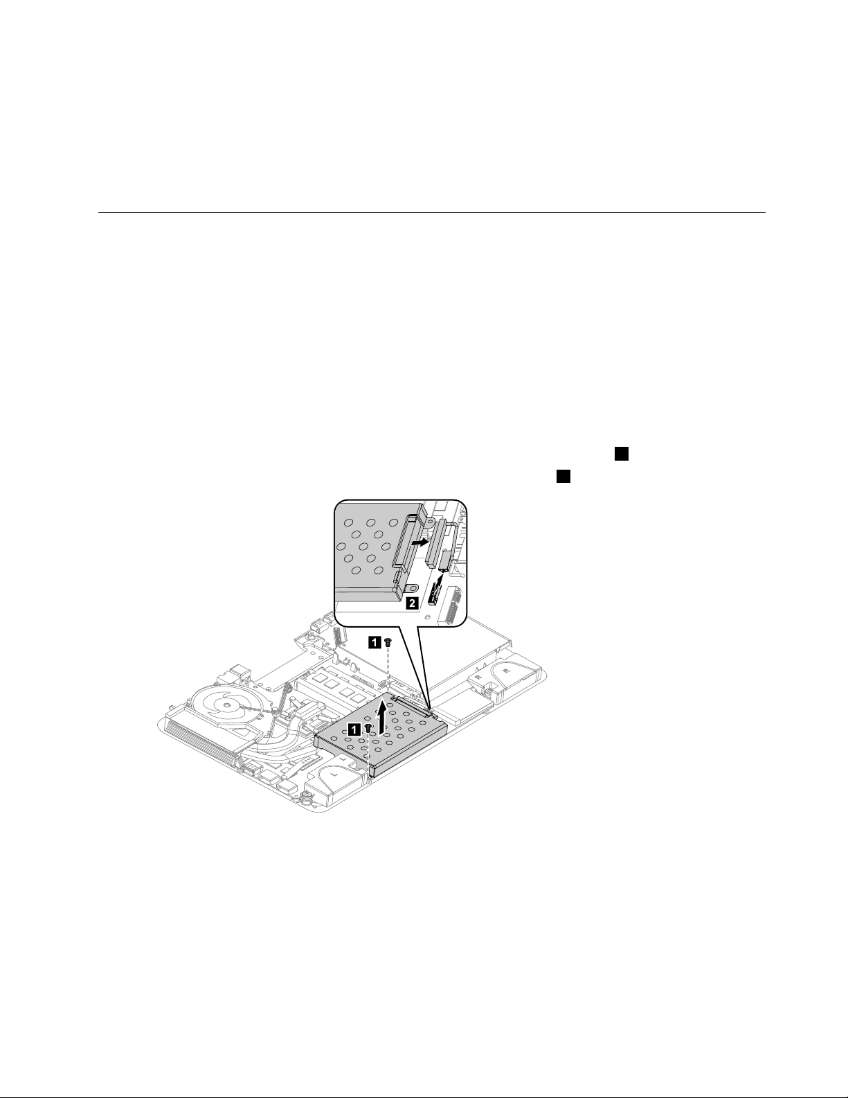
Replacingtheharddiskdrive
Attention:T urnoffthecomputerandwait3to5minutestoletitcooldownbeforeremovingthebasecover.
Toreplacetheharddiskdrive:
Step1.Removeanymedia(disks,CDs,DVDsormemorycards)fromthedrives,shutdowntheoperating
system,andturnoffthecomputerandallattacheddevices.
Step2.Unplugallpowercordsfromelectricaloutlets.
Step3.Disconnectallcablesattachedtothecomputer.Thisincludespowercords,input/output(I/O)
cables,andanyothercablesthatareconnectedtothecomputer.Referto“Leftandrightview”
and“Rearview”forhelpwithlocatingthevariousconnectors.
Step4.Removethebasecover.Referto“Removingthebasecover”.
Step5.Removethe2screwsthatsecuretheharddiskdrivetothemotherboard.1
Step6.Disconnectthedataandpowercablesfromtheharddiskdrive.2
Chapter8.Replacinghardware33
Page 40

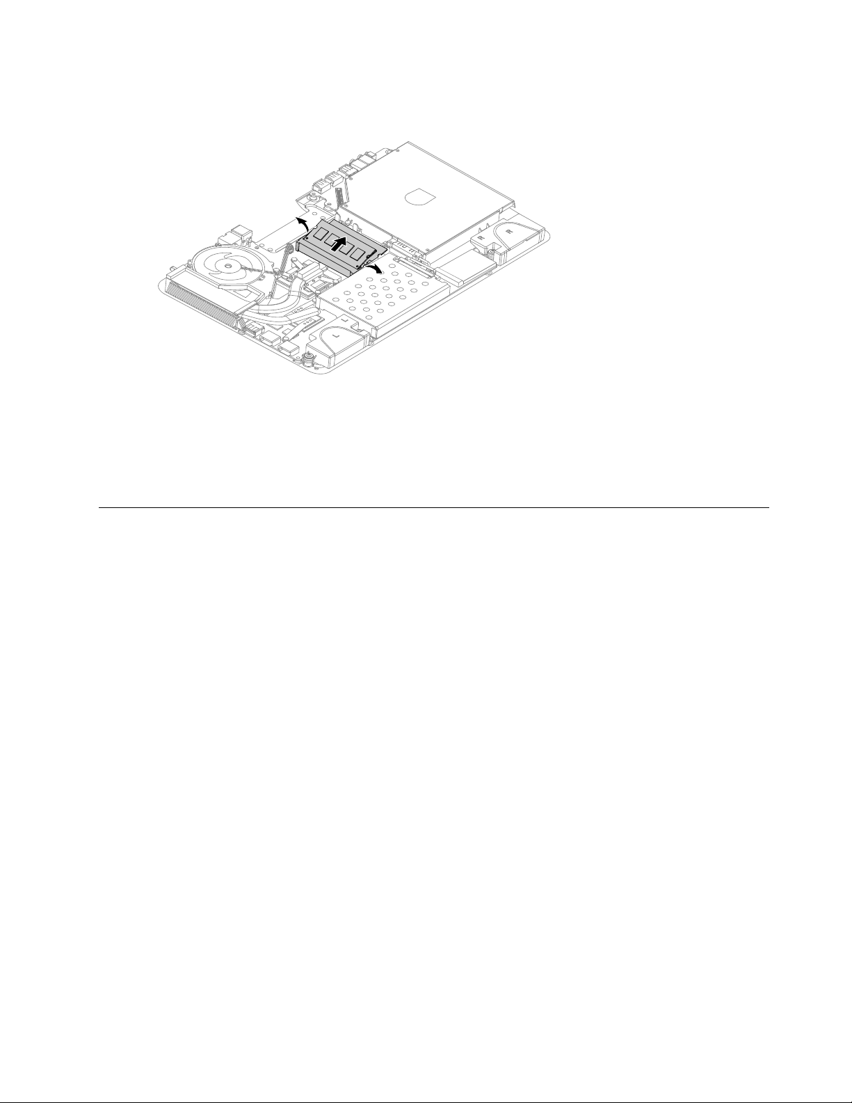
Step7.Slidetheharddiskdriveandrubbersoutofthebayasshown.
Step8.Detachtherubbersfromtheharddiskdriveasshown.
Step9.Installthenewharddiskdriveasfollows:
a.Attachtherubberstothenewharddiskdrive.
b.Slidethenewharddiskdriveintotheharddiskdrivebay.
c.Securethenewharddiskdrivetomotherboardwiththe2screws.
d.Connectthedataandpowercablestothenewharddiskdriveandtotheconnectorsonthe
motherboard.
Step10.Reattachthebasecoverandsecureitwiththescrews.
Replacingamemorymodule
Attention:T urnoffthecomputerandwait3to5minutestoletitcooldownbeforeremovingthebasecover.
Toreplaceamemorymodule:
Step1.Removeanymedia(disks,CDs,DVDs,ormemorycards)fromthedrives,shutdowntheoperating
system,andturnoffthecomputerandallattacheddevices.
Step2.Unplugallpowercordsfromelectricaloutlets.
Step3.Disconnectallcablesattachedtothecomputer.Thisincludespowercords,input/output(I/O)
cables,andanyothercablesthatareconnectedtothecomputer.Referto“Leftandrightview”
and“Rearview”forhelpwithlocatingthevariousconnectors.
Step4.Removethebasecover.Referto“Removingthebasecover”.
34IdeaCentreA530All-In-OnePCHardwareMaintenanceManual
Page 41
Step5.Pushoutthelatchesonbothsidesofthememorysockettoreleasethememorymodule.Gently
pullthememorymoduleupwardtoremoveitfromitssocket.
Step6.Toinstallthenewmemorymodule:
a.Alignthenewmemorymodulewiththememorysocket,theninsertitandpushdownon
thetopedge.
b.Makesurethelatcheslockthememorymoduleinplace.
Step7.Reattachthebasecoverandsecureitwiththescrews.
Replacingthesystemfan
Note:T urnoffthecomputerandwait3to5minutestoletitcooldownbeforeremovingthebasecover.
Toreplacethesystemfan:
Step1.Removeanymedia(disks,CDs,DVDsormemorycards)fromthedrives,shutdowntheoperating
system,andturnoffthecomputerandallattacheddevices.
Step2.Unplugallpowercordsfromelectricaloutlets.
Step3.Disconnectallcablesattachedtothecomputer.Thisincludespowercords,input/output(I/O)
cables,andanyothercablesthatareconnectedtothecomputer.Referto“Leftandrightview”
and“Rearview”forhelpwithlocatingthevariousconnectors.
Step4.Removethebasecover.Referto“Removingthebasecover”.
Chapter8.Replacinghardware35
Page 42
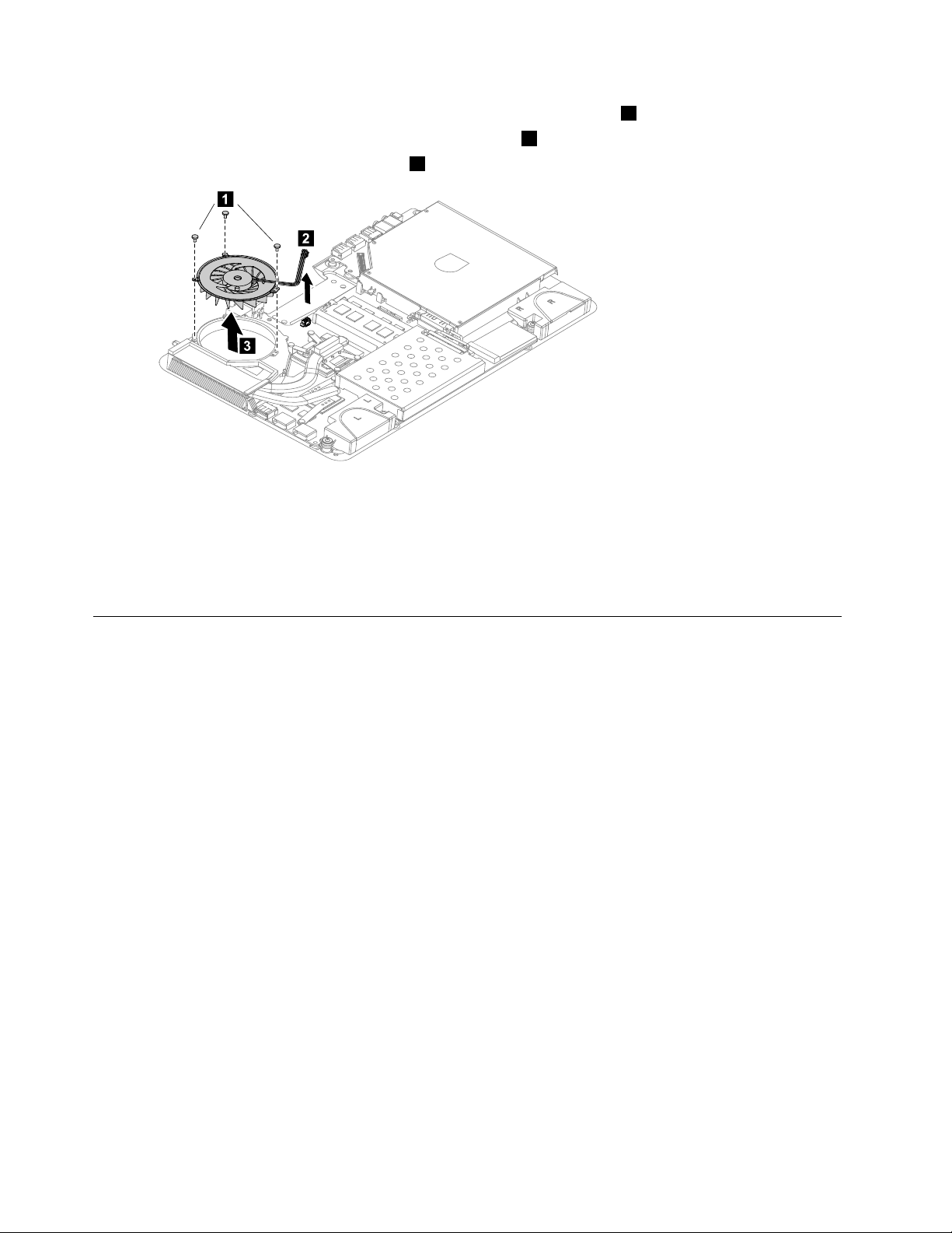
Step5.Removethe3screwsthatsecurethesystemfantotheheat-sink.1
1
2
3
Step6.Disconnectthepowercablefromthemotherboard.2
Step7.Liftupthesystemfantoremoveit.3
Step8.Toinstallthenewsystemfan:
a.Lineupthenewsystemfanwiththemountingholesontheheat-sinkandplaceitintoposition.
b.Securethenewsystemfantotheheat-sinkwiththe3screws.
c.Connectthenewpowercabletotheconnectoronmotherboard.
Step9.Reattachthebasecoverandsecureitwiththescrews.
Replacingtheheat-sink
Note:T urnoffthecomputerandwait3to5minutestoletitcooldownbeforeremovingthebasecover.
Toreplacetheheat-sink:
Step1.Removeanymedia(disks,CDs,DVDsormemorycards)fromthedrives,shutdowntheoperating
system,andturnoffthecomputerandallattacheddevices.
Step2.Unplugallpowercordsfromelectricaloutlets.
Step3.Disconnectallcablesattachedtothecomputer.Thisincludespowercords,input/output(I/O)
cables,andanyothercablesthatareconnectedtothecomputer.Referto“Leftandrightview”
and“Rearview”forhelpwithlocatingthevariousconnectors.
Step4.Removethebasecover.Referto“Removingthebasecover”.
Step5.Removethesystemfan.Referto“Replacingthesystemfan” .
36IdeaCentreA530All-In-OnePCHardwareMaintenanceManual
Page 43

Step6.Removethe9screwsthatsecuretheheat-sinktothemotherboard.
Step7.Liftuptheheat-sinktoremoveit.
Attention:Placetheheat-sinkupsidedownonaatsurfacetopreventthermalgreasefromcontaminating
othercomponents.
Step8.Toinstallthenewheat-sink:
a.UseanalcoholpadtowipethethermalgreaseofftheCPU.
b.Lineupthenewheat-sinkwithmountingholesonthemotherboard.
c.Securethenewheat-sinktothemotherboardwiththe9screws.
d.Attachthesystemfantothenewheat-sinkandsecureitwiththescrews.
Step9.Reattachthebasecoverandsecureitwiththescrews.
ReplacingtheCPU
Note:T urnoffthecomputerandwait3to5minutestoletitcooldownbeforeremovingthebasecover.
ToreplacetheCPU
Step1.Removeanymedia(disks,CDs,DVDs,ormemorycards)fromthedrives,shutdowntheoperating
system,andturnoffthecomputerandallattacheddevices.
Step2.Unplugallpowercordsfromelectricaloutlets.
Step3.Disconnectallcablesattachedtothecomputer.Thisincludespowercords,input/output(I/O)
cables,andanyothercablesthatareconnectedtothecomputer.Referto“Leftandrightview”
and“Rearview”forhelpwithlocatingthevariousconnectors.
Step4.Removethebasecover.Referto“Removingthebasecover”.
Step5.Removethesystemfan.Referto“Replacingthesystemfan” .
Step6.Removetheheat-sink.Referto“Replacingtheheat-sink” .
Chapter8.Replacinghardware37
Page 44
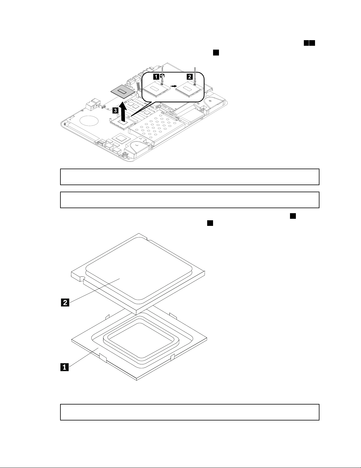
Step7.UseaatheadscrewdrivertoturntheCPUlockscrewcounterclockwisetounlocktheCPU.12
1 2
3
Step8.Liftthemicroprocessorstraightupandoutofthesocket.3
Attention:Donottouchthegoldcontactsonthebottomofthemicroprocessor.Whenhandlingthe
microprocessor,touchonlythesides.
Note:Donotdropanythingontothemicroprocessorsocketwhileitisexposed.Thesocketpinsmust
bekeptascleanaspossible.
Step9.Holdingthesidesofthemicroprocessorwithyourngers,removetheprotectivecover1that
protectsthegoldcontactsonthenewmicroprocessor.2
Step10.Holdingthesidesofthemicroprocessorwithyourngers,positionthemicroprocessorsothatthe
notchesonthemicroprocessorarealignedwiththetabsinthemicroprocessorsocket.
Important:T oavoiddamagingthemicroprocessorcontacts,keepthemicroprocessorcompletelylevel
whileinstallingitintothesocket.
38IdeaCentreA530All-In-OnePCHardwareMaintenanceManual
Page 45
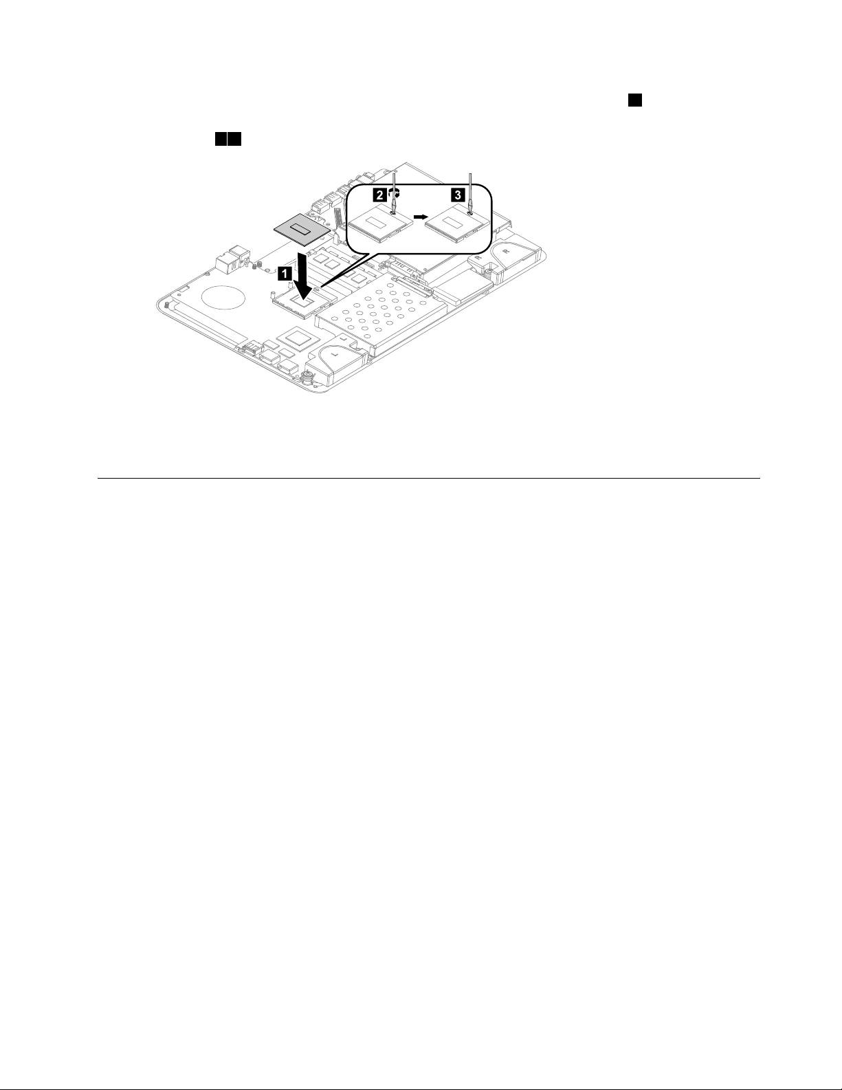
Step11.Lowerthemicroprocessorstraightdownintoitssocketonthemotherboard.1
2 3
1
Step12.TosecurethemicroprocessorbyturningtheCPUlockscrewclockwisetolocktheCPUinto
position.23
Step13.Useathermalgreasesyringetoplace5dropsofgreaseonthetopofthemicroprocessor.Each
dropofgreaseshouldbe0.03ml(3tickmarksonthegreasesyringe).
Step14.Reattachthesystemfan,heat-sink,andbasecover,thensecurethemwiththescrews.
Replacingtheopticaldrive
Attention:T urnoffthecomputerandwait3to5minutestoletitcooldownbeforeremovingthebasecover.
Toreplacetheopticaldrive:
Step1.Removeanymedia(disks,CDs,DVDs,ormemorycards)fromthedrives,shutdowntheoperating
system,andturnoffthecomputerandallattacheddevices.
Step2.Unplugallpowercordsfromelectricaloutlets.
Step3.Disconnectallcablesattachedtothecomputer.Thisincludespowercords,input/output(I/O)
cables,andanyothercablesthatareconnectedtothecomputer.Referto“Leftandrightview”
and“Rearview”forhelpwithlocatingthevariousconnectors.
Step4.Removethebasecover.Referto“Removingthebasecover”.
Step5.Disconnecttheopticaldrivedatacablefromtheconnectoronthemotherboard.
Chapter8.Replacinghardware39
Page 46

Step6.Removethe3screwsthatsecuretheopticaldrivetothemotherboardandlifttheopticaldrive
uptoremoveit.
Step7.Removethe4screwsthatsecuretheopticaldrivetothebracketanddisconnectthedata
connectorfromtherearofopticaldrive.
40IdeaCentreA530All-In-OnePCHardwareMaintenanceManual
Page 47

Step8.Useasmallatheadscrewdrivertopressandpushoutthepinsthatsecurethecovertothe
drive.12
Step9.Separatethecoverfromthedefectiveopticaldrive.
Step10.Installthenewopticaldriveasfollows:
a.Alignthenewopticaldrivewiththecover,andthenattachthecovertothenewopticaldrive.
b.Connectthedataconnectortothenewopticaldrive.
c.Alignthenewopticaldrivewiththebracket,pushitintopositionandsecureitwiththe4screws.
d.Lineuptheopticaldrivebracketwiththemountingholesonthemotherboardandsecure
itwiththe3screws.
e.Reconnectthedatacabletotheconnectoronthemotherboard.
Step11.Reattachthebasecoverandsecureitwiththescrews.
Replacingthesolidstatedisk
Note:T urnoffthecomputerandwait3to5minutestoletitcooldownbeforeremovingthebasecover.
Toreplacethesolidstatedisk:
Step1.Removeanymedia(disks,CDs,DVDs,ormemorycards)fromthedrives,shutdowntheoperating
system,andturnoffthecomputerandallattacheddevices.
Step2.Unplugallpowercordsfromelectricaloutlets.
Step3.Disconnectallcablesattachedtothecomputer.Thisincludespowercords,input/output(I/O)
cables,andanyothercablesthatareconnectedtothecomputer.Referto“Leftandrightview”
and“Rearview”forhelpwithlocatingthevariousconnectors.
Step4.Removethebasecover.Referto“Removingthebasecover”.
Chapter8.Replacinghardware41
Page 48
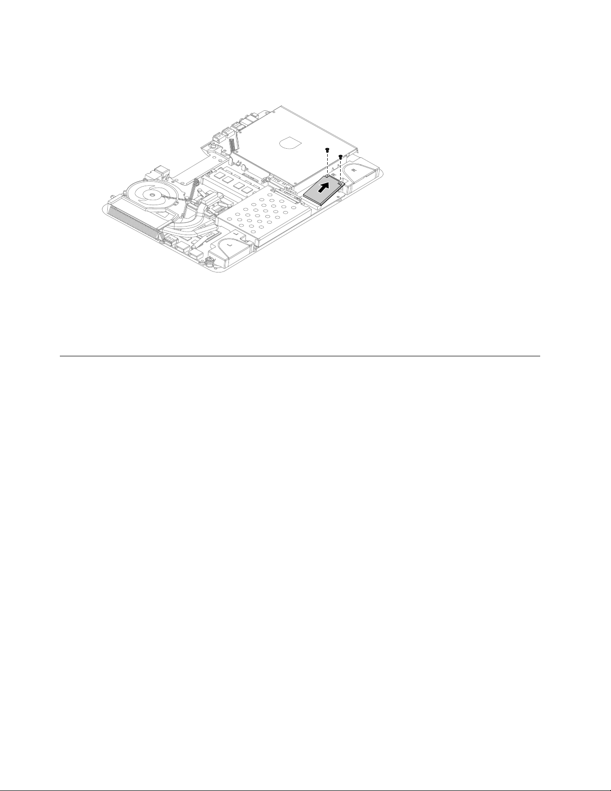
Step5.Removethe2screwsthatsecurethesolidstatedisktothemotherboard.
Step6.Pullthesolidstatediskupwardtoremoveitfromthecardport.
Step7.Toinstallthenewsolidstatedisk:
a.Insertthenotchedendofthenewsolidstatediskintothecardportonthemotherboard.
b.Securethenewsolidstatedisktothemotherboardusingthe2screws.
Step8.Reattachthebasecoverandsecureitwiththescrews.
Replacingthemotherboard
Note:T urnoffthecomputerandwait3to5minutestoletitcooldownbeforeremovingthebasecover.
Toreplacethemotherboard:
Step1.Removeanymedia(disks,CDs,DVDs,ormemorycards)fromthedrives,shutdowntheoperating
system,andturnoffthecomputerandallattacheddevices.
Step2.Unplugallpowercordsfromelectricaloutlets.
Step3.Disconnectallcablesattachedtothecomputer.Thisincludespowercords,input/output(I/O)
cables,andanyothercablesthatareconnectedtothecomputer.Referto“Leftandrightview”
and“Rearview”forhelpwithlocatingthevariousconnectors.
Step4.Removethebasecover.Referto“Removingthebasecover”.
Step5.Removetheharddiskdrive.Referto“Replacingtheharddiskdrive” .
Step6.Removeallmemorymodules.Referto“Replacingamemorymodule” .
Step7.Removetheopticaldrive.Referto“Replacingtheopticaldrive” .
Step8.Removethesystemfan.Referto“Replacingthesystemfan” .
Step9.Removetheheat-sink.Referto“Replacingtheheat-sink” .
Step10.RemovetheCPU.Referto“ReplacingtheCPU” .
Step11.Removethesolidstatedisk.Referto“Replacingthesolidstatedisk” .
Step12.Removeallthecablesconnectedtothemotherboard.
Step13.Removethe4screwsthatsecurethespeakers,thendetachthemfromthechassisandputthem
aside.
42IdeaCentreA530All-In-OnePCHardwareMaintenanceManual
Page 49

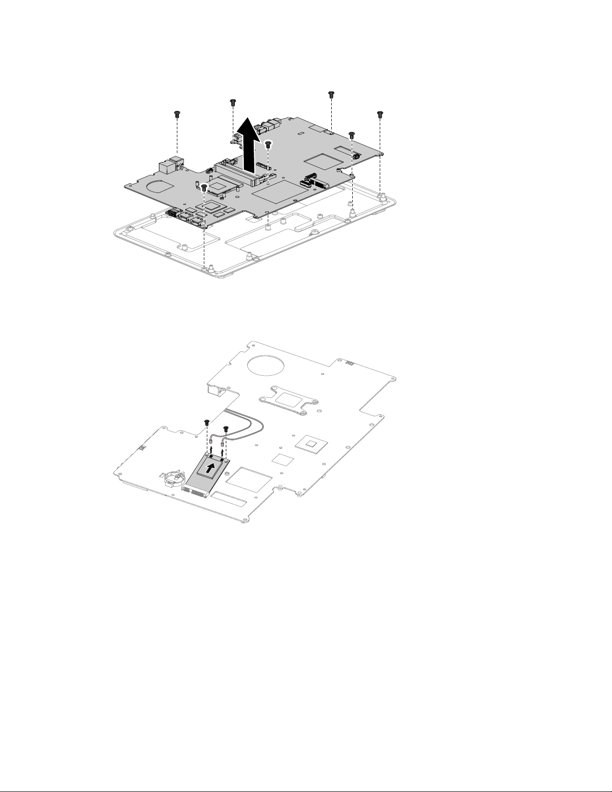
Step14.Removethe7screwsthatsecurethemotherboardtothechassisandslideitoutasshown.
Step15.Removethe2screwsthatsecuretheTV-Tunercardtothemotherboard.
Step16.Disconnecttheantennacable(s)fromtheTV- T unercard.
Step17.PulltheTV- T unercardupwardtoremoveitfromthecardport.
Chapter8.Replacinghardware43
Page 50

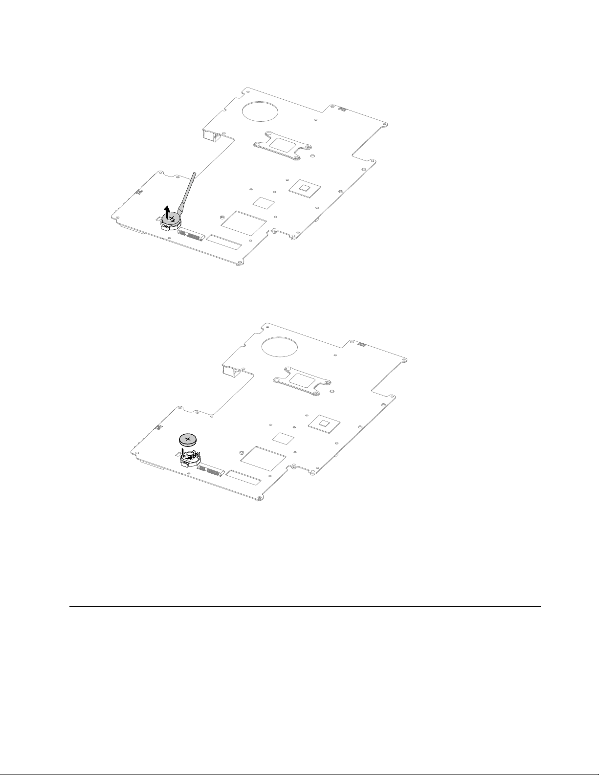
Step18.Useaatheadscrewdriverasalevertopriseoutthebatterygentlyasshown.
Step19.Toinstallthenewmotherboard:
a.Insertthebattery(CR2032)intothesocketwiththesidelabeled“+”facingup,andpress
thebatteryintoplace.
b.InsertthenotchedendoftheTV-Tunercardintothecardportonthenewmotherboardand
secureitwiththe2screws.
c.Connecttheantennacable(s)totheTV- T unercard.
d.Lineupthenewmotherboardwiththechassisandslideitintoposition.Aligntheholeson
thenewmotherboardwiththemountingholesonthechassisandsecureittothechassis
withthescrews.
e.Attachthespeakerstothechassiswiththescrews.
f.Attachthesolidstatedisk,opticaldrive,CPU,heat-sink,systemfan,memorymodule,and
harddiskdrivetothenewmotherboard.
g.Connectallthecablestothenewmotherboard.
Step20.Reattachthebasecoverandsecureitwiththescrews.
44IdeaCentreA530All-In-OnePCHardwareMaintenanceManual
Page 51

Replacingthespeakersystem
Note:T urnoffthecomputerandwait3to5minutestoletitcooldownbeforeremovingthebasecover.
Toreplacethespeakersystem:
Step1.Removeanymedia(disks,CDs,DVDs,ormemorycards)fromthedrives,shutdowntheoperating
system,andturnoffthecomputerandallattacheddevices.
Step2.Unplugallpowercordsfromelectricaloutlets.
Step3.Disconnectallcablesattachedtothecomputer.Thisincludespowercords,input/output(I/O)
cables,andanyothercablesthatareconnectedtothecomputer.Referto“Leftandrightview”
and“Rearview”forhelpwithlocatingthevariousconnectors.
Step4.Removethebasecover.Referto“Removingthebasecover”.
Step5.Removetheharddiskdrive.Referto“Replacingtheharddiskdrive” .
Step6.Removetheopticaldrive.Referto“Replacingtheopticaldrive” .
Step7.Removethesystemfan.Referto“Replacingthesystemfan” .
Step8.Removetheheat-sink.Referto“Replacingtheheat-sink” .
Step9.Removeallthecablesconnectedtothemotherboard.
Step10.Removethe4screwsthatsecurethespeakers,thendetachthespeakersfromthechassisand
putthemaside.
Step11.Removethe7screwsthatsecurethemotherboardtothechassisandslideitoutasshown.
Chapter8.Replacinghardware45
Page 52

Step12.Detachthespeakersfromthechassis.
Step13.Toinstallthenewspeakersystem:
a.Attachthenewspeakercabletothechassis.
b.Lineupthemotherboardwiththechassisandslideitintoposition.Aligntheholesonthe
motherboardwiththemountingholesonthechassisandsecureittothechassiswiththe
7screws.
c.Lineupthenewspeakersystemwiththemountingholesonthechassisandsecurethenew
speakersystemwiththe4screws.
d.Connectthenewspeakercabletotheconnectoronthemotherboard.
Step14.Reattachtheopticaldrive,heat-sink,systemfan,andharddiskdrivetothemotherboard.
Step15.Reattachthebasecoverandsecureitwiththescrews.
ReplacingtheTVtunercard
Note:T urnoffthecomputerandwait3to5minutestoletitcooldownbeforeremovingthebasecover.
ToreplacetheTVtunercard:
Step1.Removeanymedia(disks,CDs,DVDs,ormemorycards)fromthedrives,shutdowntheoperating
system,andturnoffthecomputerandallattacheddevices.
Step2.Unplugallpowercordsfromelectricaloutlets.
Step3.Disconnectallcablesattachedtothecomputer.Thisincludespowercords,input/output(I/O)
cables,andanyothercablesthatareconnectedtothecomputer.Referto“Leftandrightview”
and“Rearview”forhelpwithlocatingthevariousconnectors.
Step4.Removethebasecover.Referto“Removingthebasecover”.
Step5.Removetheharddiskdrive.Referto“Replacingtheharddiskdrive” .
Step6.Removetheopticaldrive.Referto“Replacingtheopticaldrive” .
Step7.Removethesystemfan.Referto“Replacingthesystemfan” .
Step8.Removetheheat-sink.Referto“Replacingtheheat-sink” .
Step9.Removeallthecablesconnectedtothemotherboard.
Step10.Removethe4screwsthatsecurethespeakers,thendetachthemfromthechassisandputthem
aside.
46IdeaCentreA530All-In-OnePCHardwareMaintenanceManual
Page 53
Step11.Removethe7screwsthatsecurethemotherboardtothechassisandslideitoutasshown.
Step12.Removethe2screwsthatsecuretheTV-Tunercardtothemotherboard.
Step13.Disconnecttheantennacable(s)fromtheTV- T unercard.
Step14.PulltheTV- T unercardupwardtoremoveitfromthecardport.
Step15.ToinstallthenewTV-Tunercard:
a.InsertthenotchedendoftheTV-Tunercardintothecardport.
b.SecurethenewTV-Tunercardtothemotherboardwiththe2screws.
c.Connecttheantennacable(s)tothenewTV-Tunercard.
Step16.Lineupthemotherboardwiththechassisandslideitintoposition.Aligntheholesonthe
motherboardwiththemountingholesonthechassisandsecurethemotherboardtothechassis
withthe7screws.
Step17.Reattachthespeakersystem,opticaldrive,heat-sink,systemfan,andharddiskdrivetothe
motherboard.
Step18.Reconnectallthecablestothemotherboard.
Step19.Reattachthebasecoverandsecureitwiththescrews.
Chapter8.Replacinghardware47
Page 54

Replacingthebattery
Note:T urnoffthecomputerandwait3to5minutestoletitcooldownbeforeremovingthebasecover.
Toreplacethebattery:
Step1.Removeanymedia(disks,CDs,DVDs,ormemorycards)fromthedrives,shutdowntheoperating
system,andturnoffthecomputerandallattacheddevices.
Step2.Unplugallpowercordsfromelectricaloutlets.
Step3.Disconnectallcablesattachedtothecomputer.Thisincludespowercords,input/output(I/O)
cables,andanyothercablesthatareconnectedtothecomputer.Referto“Leftandrightview”
and“Rearview”forhelpwithlocatingthevariousconnectors.
Step4.Removethebasecover.Referto“Removingthebasecover”.
Step5.Removetheharddiskdrive.Referto“Replacingtheharddiskdrive” .
Step6.Removetheopticaldrive.Referto“Replacingtheopticaldrive” .
Step7.Removethesystemfan.Referto“Replacingthesystemfan” .
Step8.Removetheheat-sink.Referto“Replacingtheheat-sink” .
Step9.Removeallthecablesconnectedtothemotherboard.
Step10.Removethe4screwsthatsecurethespeakers,thendetachthespeakersfromthechassisand
putthemaside.
Step11.Removethe7screwsthatsecurethemotherboardtothechassisandslideitoutasshown.
48IdeaCentreA530All-In-OnePCHardwareMaintenanceManual
Page 55
Step12.Useaatheadscrewdriverasalevertopriseoutthebatteryasshown.
Step13.Toinstallthenewbattery:
a.Insertthenewbattery(CR2032)intothesocketwiththesidelabeled“+”facingup,andpress
thebatteryintoplace.
Step14.Lineupthemotherboardwiththechassisandslideitintoposition.Aligntheholesonthe
motherboardwiththemountingholesonthechassisandsecureittothechassiswiththescrews.
Step15.Reattachthespeakersystem,opticaldrive,heat-sink,systemfan,andharddiskdrivetothe
motherboard.
Step16.Reconnectallthecablestothemotherboard.
Step17.Reattachthebasecoverandsecureitwiththescrews.
Removingthehingefromthechassis
Note:T urnoffthecomputerandwait3to5minutestoletitcooldownbeforeremovingthebasecover.
Toremovethehingefromthechassis:
Step1.Removeanymedia(disks,CDs,DVDs,ormemorycards)fromthedrives,shutdowntheoperating
system,andturnoffthecomputerandallattacheddevices.
Step2.Unplugallpowercordsfromelectricaloutlets.
Chapter8.Replacinghardware49
Page 56
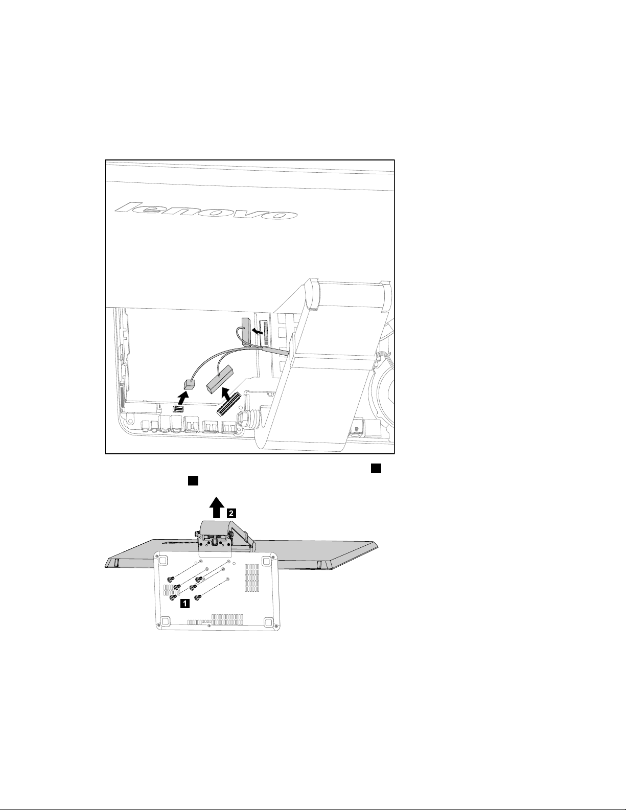
Step3.Disconnectallcablesattachedtothecomputer.Thisincludespowercords,input/output(I/O)
1
2
cables,andanyothercablesthatareconnectedtothecomputer.Referto“Leftandrightview”
and“Rearview”forhelpwithlocatingthevariousconnectors.
Step4.Removethebasecover.Referto“Removingthebasecover”.
Step5.Disconnectthescalarheadphoneinput,scalarandDVI/HDMIcablesfromtheconnectorson
themotherboard.
Step6.Removethe6screwsthatsecurethehingetothechassis1,thenliftupthehingetoremoveit
fromthechassis.2
Step7.Toreattachthehingetothechassis:
a.Lineupthehingewiththechassisandslidethehingeintoposition.
b.Securethehingetothechassiswiththe6screws.
c.Reconnectthescalarheadphoneinput,scalarandDVI/HDMIcablestothemotherboard.
Step8.Reattachthebasecoverandsecureitwiththescrews.
50IdeaCentreA530All-In-OnePCHardwareMaintenanceManual
Page 57

Replacingthehingecable
Note:T urnoffthecomputerandwait3to5minutestoletitcooldownbeforeremovingthebasecover.
Toreplacethehingecable:
Step1.Removeanymedia(disks,CDs,DVDs,ormemorycards)fromthedrives,shutdowntheoperating
system,andturnoffthecomputerandallattacheddevices.
Step2.Unplugallpowercordsfromelectricaloutlets.
Step3.Disconnectallcablesattachedtothecomputer.Thisincludespowercords,input/output(I/O)
cables,andanyothercablesthatareconnectedtothecomputer.Referto“Leftandrightview”
and“Rearview”forhelpwithlocatingthevariousconnectors.
Step4.Removethebasecover.Referto“Removingthebasecover”.
Step5.Disconnectthescalarheadphoneinput,scalarandDVI/HDMIcablesfromtheconnectorson
themotherboard.
Chapter8.Replacinghardware51
Page 58

Step6.Removethe6screwsthatsecurethehingetothechassis1,thenraisethehingetoremoveit
1
2
1
2
Leve r
Fulcru m
1
2
fromthechassis.2
Step7.Raisethehinge1andslidethereardecooutasshown.2
Step8.Puttheheadofaatheadscrewdriverbetweenthemiddleframeandtherearcoverasshown.
Thenusingthescrewdriverasaleverandthemiddleframemetalbarasthefulcrum,prisetherear
coverawayfromthemiddleframe.
1
Step9.Workingaroundtheedgeinananti-clockwisedirection,useyourngerstopriseuptherearcover.
Therearcoverispinnedintoplace,useshort,sharpmovementstopriseitup.2
Step10.Pressdownthehingeandslideouttherearcover.
52IdeaCentreA530All-In-OnePCHardwareMaintenanceManual
Page 59

Step11.Disconnectthescalar10andHDMI/DVI11cablesfromtheconnectorsonthescalarboard.
LED/CIR
LVDS
MMB
Po wer
Blue tooth
WLAN
Ca mera
Con verte r
Touch co ntrol
Sc alar
HDMI/DVI
Step12.Removethe5screwsthatsecurethehingetothemiddleframeandsetthehingeaside.
Chapter8.Replacinghardware53
Page 60
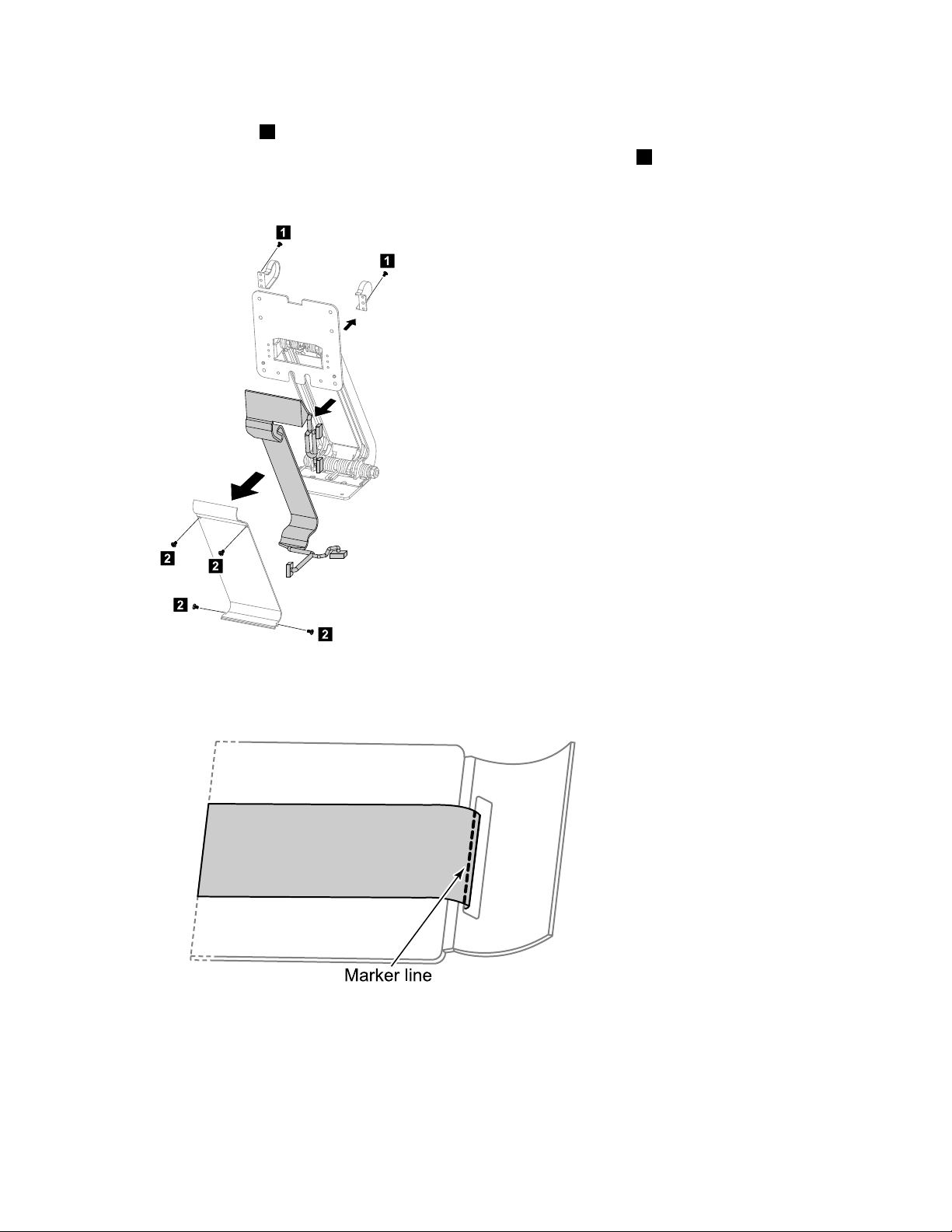
Step13.Removethe2screwsthatsecurethehingecoverpiecestothehinge,andthenremovethe2
1
1
2
2
2
2
Marke r line
coverpieces.1
Step14.Removethe4screwsthatsecurethehingefrontcovertothehinge.2
Step15.Useaatheadscrewdrivertoprisethefrontcoveroffgently,andthendetachthehingecable
fromthefrontcover.
Step16.Toinstallthenewhingecable:
a.Slidethenewhingecablethroughthemountingholeonthefrontcover.
b.Lineupthemarkerlineonthenewhingecablewiththebottomsideofthemountinghole.
c.Stickthenewhingecabletothefrontcover.
d.Lineupthefrontcoverwiththehinge,thenplaceitintopositionandsecureitwiththe4screws.
e.Reattachthehingecoverpiecesandsecurethemwiththe2screws.
f.LineupthehingewiththemountingholesonthebackoftheLEDpanelandsecureitwiththe
5screws.
54IdeaCentreA530All-In-OnePCHardwareMaintenanceManual
Page 61

g.ConnectthenewscalarandHDMI/DVIcablestotheconnectorsonthescalarboard.
1
2
Leve r
Fulcru m
1
h.ReattachtherearcovertotheLEDpanel.
i.Reattachthehingetothebaseandsecureitwiththe6screws.
j.Connectthenewscalarheadphoneinput,scalarandDVI/HDMIcablestotheconnectors
onthemotherboard.
Step17.Reattachthebasecoverandsecureitwiththescrews.
Removingtherearcover
Note:T urnoffthecomputerandwait3to5minutestoletitcooldownbeforeremovingthebasecover.
Toremovetherearcover:
Step1.Removeanymedia(disks,CDs,DVDs,ormemorycards)fromthedrives,shutdowntheoperating
system,andturnoffthecomputerandallattacheddevices.
Step2.Unplugallpowercordsfromelectricaloutlets.
Step3.Disconnectallcablesattachedtothecomputer.Thisincludespowercords,input/output(I/O)
cables,andanyothercablesthatareconnectedtothecomputer.Referto“Leftandrightview”
and“Rearview”forhelpwithlocatingthevariousconnectors.
Step4.Removethebasecover.Referto“Removingthebasecover”.
Step5.Removethehingefromthechassis.Referto“Removingthehingefromthechassis” .
Step6.Raisethehinge1andslidethereardecooutasshown.2
Step7.Puttheheadofaatheadscrewdriverbetweenthemiddleframeandtherearcoverasshown.
Thenusingthescrewdriverasaleverandthemiddleframemetalbarasthefulcrum,prisetherear
coverawayfromthemiddleframe.1
Chapter8.Replacinghardware55
Page 62
Step8.Workingaroundtheedgeinananti-clockwisedirection,useyourngerstopriseuptherearcover.
2
Therearcoverispinnedintoplace,useshort,sharpmovementstopriseitup.2
Step9.Pressdownthehingeandslideouttherearcover.
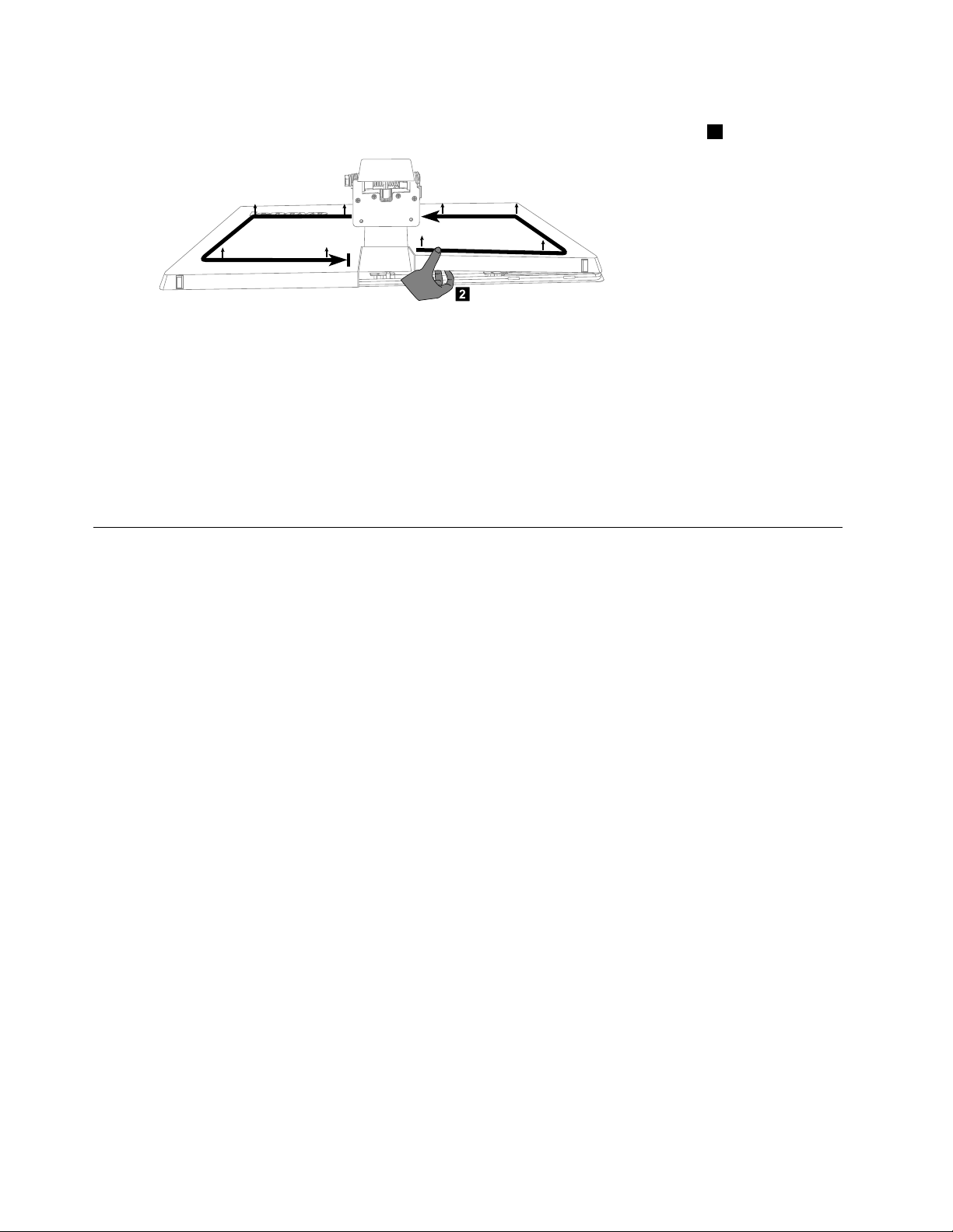
Step10.Toreattachtherearcover:
a.Raisethehinge,lineuptherearcoverwiththeLEDpanelandslideitbackintoposition.
b.PresstheedgeofrearcovertolockthecovertotheLEDpanelwiththepins.
c.Slidethereardecobackintoposition.
Step11.Reattachthehingetothechassis,andreconnectthescalarheadphoneinput,scalarandDVI/HDMI
cablestothemotherboard.
Step12.Reattachthebasecoverandsecureitwiththescrews.
Replacingthescalarboard
Note:T urnoffthecomputerandwait3to5minutestoletitcooldownbeforeremovingthebasecover.
Toreplacethescalarboard:
Step1.Removeanymedia(disks,CDs,DVDs,ormemorycards)fromthedrives,shutdowntheoperating
system,andturnoffthecomputerandallattacheddevices.
Step2.Unplugallpowercordsfromelectricaloutlets.
Step3.Disconnectallcablesattachedtothecomputer.Thisincludespowercords,input/output(I/O)
cables,andanyothercablesthatareconnectedtothecomputer.Referto“Leftandrightview”
and“Rearview”forhelpwithlocatingthevariousconnectors.
Step4.Removethebasecover.Referto“Removingthebasecover”.
Step5.Removethehingefromthechassis.Referto“Removingthehingefromthechassis” .
Step6.Removetherearcover.Referto“Removingtherearcover”.
56IdeaCentreA530All-In-OnePCHardwareMaintenanceManual
Page 63

Step7.Disconnectallthecablesfromthescalarboard.1-11
LED/CIR
LVDS
MMB
Po wer
Blue tooth
WLAN
Ca mera
Con verte r
Touch co ntrol
Sc alar
HDMI/DVI
Step8.Removethe5screwsthatsecurethescalarboardtothemiddleframeandliftituptoremoveit.
Step9.Toinstallthenewscalarboard:
a.Lineuptheholesonthenewscalarboardwiththemountingholesonthemiddleframeand
securethenewscalarboardwiththe5screws.
b.Connectallthecablestothenewscalarboard.
Step10.ReattachtherearcovertotheLEDpanel.
Step11.Reattachthehingetothechassis,andreconnectthescalarheadphoneinput,scalarandDVI/HDMI
cablestothemotherboard.
Step12.Reattachthebasecoverandsecureitwiththescrews.
Replacingthetouchcontrolboard
Note:T urnoffthecomputerandwait3to5minutestoletitcooldownbeforeremovingthebasecover.
Toreplacethetouchcontrolboard:
Step1.Removeanymedia(disks,CDs,DVDs,ormemorycards)fromthedrives,shutdowntheoperating
system,andturnoffthecomputerandallattacheddevices.
Step2.Unplugallpowercordsfromelectricaloutlets.
Step3.Disconnectallcablesattachedtothecomputer.Thisincludespowercords,input/output(I/O)
cables,andanyothercablesthatareconnectedtothecomputer.Referto“Leftandrightview”
and“Rearview”forhelpwithlocatingthevariousconnectors.
Step4.Removethebasecover.Referto“Removingthebasecover”.
Step5.Removethehingefromthechassis.Referto“Removingthehingefromthechassis” .
Step6.Removetherearcover.Referto“Removingtherearcover”.
Step7.Disconnectallthetouchcablesfromthetouchcontrolboard.
Chapter8.Replacinghardware57
Page 64

Step8.Liftupthetouchcontrolboardtoremoveitfromthemiddleframe.
Step9.Toinstallthenewtouchcontrolboard:
a.Connectallthecablestothenewtouchcontrolboard.
b.Removetheinsulatingpaper(siliconedpaper)ofthedoublesidedtapeonthenewtouch
controlboard.
c.Lineupthenewtouchcontrolboardwiththemountingmarksonthemiddleframe,then
stickittothemiddleframe.
Step10.ReattachtherearcovertotheLEDpanel.
Step11.Reattachthehingetothechassis,andreconnectthescalarheadphoneinput,scalarandDVI/HDMI
cablestothemotherboard.
Step12.Reattachthebasecoverandsecureitwiththescrews.
Replacingtheconverterboard
Note:T urnoffthecomputerandwait3to5minutestoletitcooldownbeforeremovingthebasecover.
Toreplacetheconverterboard:
Step1.Removeanymedia(disks,CDs,DVDs,ormemorycards)fromthedrives,shutdowntheoperating
system,andturnoffthecomputerandallattacheddevices.
Step2.Unplugallpowercordsfromelectricaloutlets.
Step3.Disconnectallcablesattachedtothecomputer.Thisincludespowercords,input/output(I/O)
cables,andanyothercablesthatareconnectedtothecomputer.Referto“Leftandrightview”
and“Rearview”forhelpwithlocatingthevariousconnectors.
Step4.Removethebasecover.Referto“Removingthebasecover”.
Step5.Removethehingefromthechassis.Referto“Removingthehingefromthechassis” .
58IdeaCentreA530All-In-OnePCHardwareMaintenanceManual
Page 65

Step6.Removetherearcover.Referto“Removingtherearcover”.
Step7.Removethe4screwsthatsecuretheconverterboardtothemiddleframe.
Step8.Disconnectthe2cablesfromtheconverterboard.
Step9.Liftuptheconverterboardtoremoveit.
Step10.Toinstallthenewconverterboard:
a.Lineuptheholesonthenewconverterboardwiththemountingholesonthemiddleframe
andsecureitwiththe4screws.
b.Connectthe2cablestothenewconverterboard.
Step11.ReattachtherearcovertotheLEDpanel.
Step12.Reattachthehingetothechassis,andreconnectthescalarheadphoneinput,scalarandDVI/HDMI
cablestothemotherboard.
Step13.Reattachthebasecoverandsecureitwiththescrews.
Replacingthepowerswitchboard
Note:T urnoffthecomputerandwait3to5minutestoletitcooldownbeforeremovingthebasecover.
Toreplacethepowerswitchboard:
Step1.Removeanymedia(disks,CDs,DVDs,ormemorycards)fromthedrives,shutdowntheoperating
system,andturnoffthecomputerandallattacheddevices.
Step2.Unplugallpowercordsfromelectricaloutlets.
Step3.Disconnectallcablesattachedtothecomputer.Thisincludespowercords,input/output(I/O)
cables,andanyothercablesthatareconnectedtothecomputer.Referto“Leftandrightview”
and“Rearview”forhelpwithlocatingthevariousconnectors.
Chapter8.Replacinghardware59
Page 66

Step4.Removethebasecover.Referto“Removingthebasecover”.
Step5.Removethehingefromthechassis.Referto“Removingthehingefromthechassis” .
Step6.Removetherearcover.Referto“Removingtherearcover”.
Step7.Disconnectthepowercablefromthepowerswitchboard.
Step8.RemovethescrewthatsecuresthepowerswitchboardtotheLEDpanelandliftupthepower
switchboardtoremoveit.
Step9.Toinstallthepowerswitchboard:
a.LineuptheholeonthenewpowerswitchboardwiththemountingholeontheLEDpaneland
secureitwiththescrew.
b.Connectthepowercabletothenewconverterboard.
Step10.ReattachtherearcovertotheLEDpanel.
Step11.Reattachthehingetothechassis,andreconnectthescalarheadphoneinput,scalarandDVI/HDMI
cablestothemotherboard.
Step12.Reattachthebasecoverandsecureitwiththescrews.
ReplacingtheBluetoothmodule
Attention:T urnoffthecomputerandwait3to5minutestoletitcooldownbeforeremovingthebasecover.
ToreplacetheBluetoothmodule:
Step1.Removeanymedia(disks,CDs,DVDs,ormemorycards)fromthedrives,shutdowntheoperating
system,andturnoffthecomputerandallattacheddevices.
Step2.Unplugallpowercordsfromelectricaloutlets.
Step3.Disconnectallcablesattachedtothecomputer.Thisincludespowercords,input/output(I/O)
cables,andanyothercablesthatareconnectedtothecomputer.Referto“Leftandrightview”
and“Rearview”forhelpwithlocatingthevariousconnectors.
Step4.Removethebasecover.Referto“Removingthebasecover”.
Step5.Removethehingefromthechassis.Referto“Removingthehingefromthechassis” .
60IdeaCentreA530All-In-OnePCHardwareMaintenanceManual
Page 67
Step6.Removetherearcover.Referto“Removingtherearcover”.
1
2
3
Step7.PushthepinsouttoreleasetheBluetoothmodule,thenliftituptoremoveitfromthesocket.12
Step8.DisconnectthecablefromtheBluetoothmodule.3
Step9.ToinstallthenewBluetoothmodule:
a.ConnectthecabletothenewBluetoothmodule.
b.LineupthenewBluetoothmodulewiththesocket,snapitintopositionandsecureitwith
thepins.
Step10.ReattachtherearcovertotheLEDpanel.
Step11.Reattachthehingetothechassis,andreconnectthescalarheadphoneinput,scalarandDVI/HDMI
cablestothemotherboard.
Step12.Reattachthebasecoverandsecureitwiththescrews.
ReplacingtheWi-Ficard
Note:T urnoffthecomputerandwait3to5minutestoletitcooldownbeforeremovingthebasecover.
ToreplacetheWi-Ficard:
Step1.Removeanymedia(disks,CDs,DVDs,ormemorycards)fromthedrives,shutdowntheoperating
system,andturnoffthecomputerandallattacheddevices.
Step2.Unplugallpowercordsfromelectricaloutlets.
Step3.Disconnectallcablesattachedtothecomputer.Thisincludespowercords,input/output(I/O)
cables,andanyothercablesthatareconnectedtothecomputer.Referto“Leftandrightview”
and“Rearview”forhelpwithlocatingthevariousconnectors.
Step4.Removethebasecover.Referto“Removingthebasecover”.
Step5.Removethehingefromthechassis.Referto“Removingthehingefromthechassis” .
Step6.Removetherearcover.Referto“Removingtherearcover”.
Chapter8.Replacinghardware61
Page 68

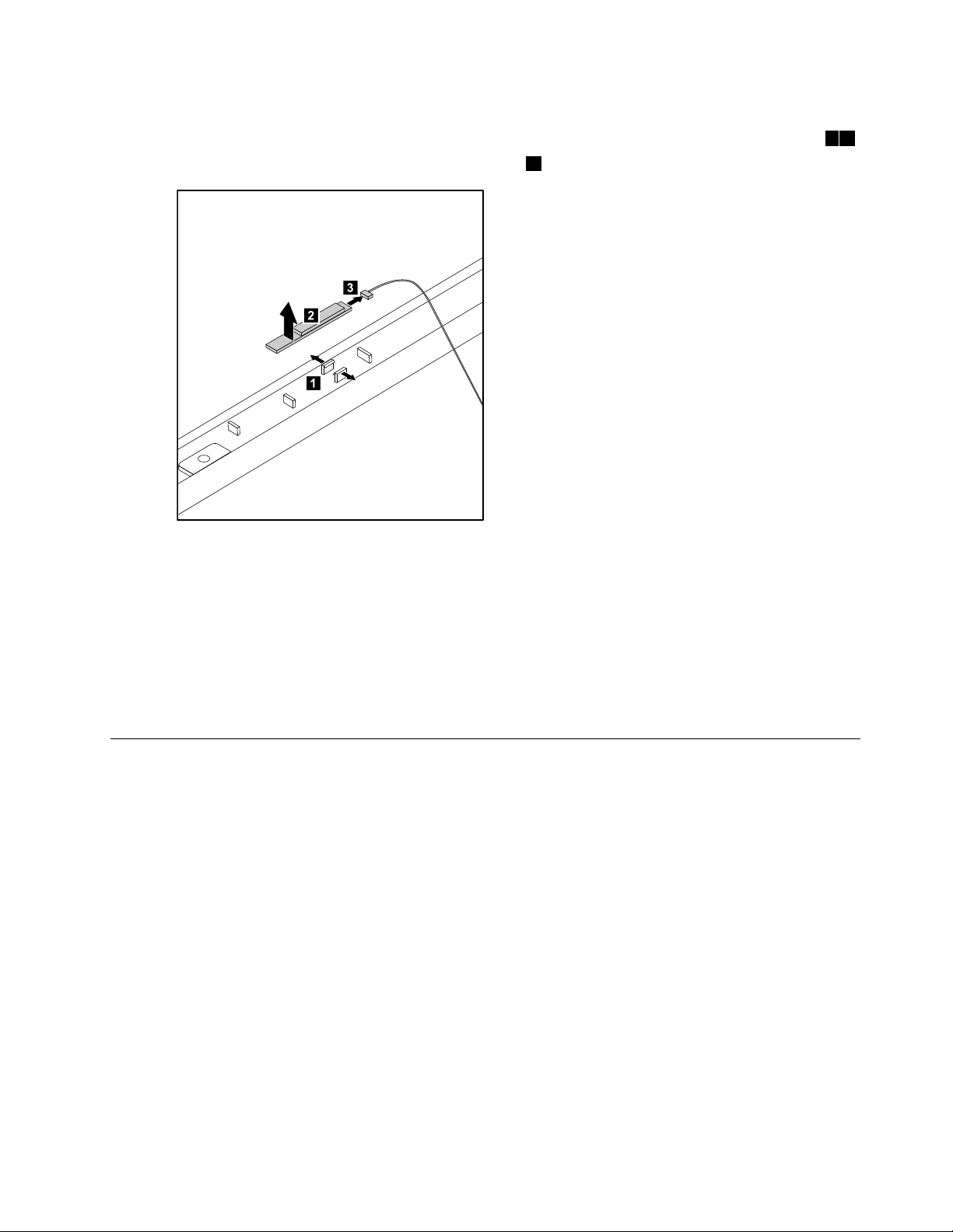
Step7.UseasmallatheadscrewdrivertoprisetheWi-Ficardawayfromthesocket.12
1
1
1
1
2
4
3
Step8.Disconnecttheantennacable3anddatacable4fromtheWi-Ficard.
Step9.ToinstallthenewWi-Ficard:
a.ConnectthedatacabletothenewWi-Ficard.
b.LineupthenewWi-Ficardwiththesocket,snapitintopositionandsecureitwiththepins.
c.ReconnecttheantennacabletothenewWi-Ficard.
Step10.ReattachtherearcovertotheLEDpanel.
Step11.Reattachthehingetothechassis,andreconnectthescalarheadphoneinput,scalarandDVI/HDMI
cablestothemotherboard.
Step12.Reattachthebasecoverandsecureitwiththescrews.
Replacingthecamera
Note:T urnoffthecomputerandwait3to5minutestoletitcooldownbeforeremovingthebasecover.
Toreplacethecamera:
Step1.Removeanymedia(disks,CDs,DVDs,ormemorycards)fromthedrives,shutdowntheoperating
system,andturnoffthecomputerandallattacheddevices.
Step2.Unplugallpowercordsfromelectricaloutlets.
Step3.Disconnectallcablesattachedtothecomputer.Thisincludespowercords,input/output(I/O)
cables,andanyothercablesthatareconnectedtothecomputer.Referto“Leftandrightview”
and“Rearview”forhelpwithlocatingthevariousconnectors.
Step4.Removethebasecover.Referto“Removingthebasecover”.
Step5.Removethehingefromthechassis.Referto“Removingthehingefromthechassis” .
Step6.Removetherearcover.Referto“Removingtherearcover”.
62IdeaCentreA530All-In-OnePCHardwareMaintenanceManual
Page 69
Step7.Removethe2screwsthatsecurethecameratothefrontbezel.1
1
2
3
1
Step8.Liftupthecamera2anddisconnectthedatacablefromthecamera.3
Step9.Toinstallthenewcamera:
a.Connectthedatacabletothenewcamera.
b.Lineuptheholesinthenewcamerawiththemountingholesonthefrontbezelandsecure
thenewcamerawiththe2screws.
Step10.ReattachtherearcovertotheLEDpanel.
Step11.Reattachthehingetothechassis.
Step12.Reconnectthescalarheadphoneinput,scalarandDVI/HDMIcablestothemotherboard.
Step13.Reattachthebasecoverandsecureitwiththescrews.
Replacingthefrontfunctionboard
Note:T urnoffthecomputerandwait3to5minutestoletitcooldownbeforeremovingthebasecover.
Toreplacethefrontfunctionboard:
Step1.Removeanymedia(disks,CDs,DVDs,ormemorycards)fromthedrives,shutdowntheoperating
system,andturnoffthecomputerandallattacheddevices.
Step2.Unplugallpowercordsfromelectricaloutlets.
Step3.Disconnectallcablesattachedtothecomputer.Thisincludespowercords,input/output(I/O)
cables,andanyothercablesthatareconnectedtothecomputer.Referto“Leftandrightview”
and“Rearview”forhelpwithlocatingthevariousconnectors.
Step4.Removethebasecover.Referto“Removingthebasecover”.
Step5.Removethehingefromthechassis.Referto“Removingthehingefromthechassis” .
Step6.Removetherearcover.Referto“Removingtherearcover”.
Chapter8.Replacinghardware63
Page 70

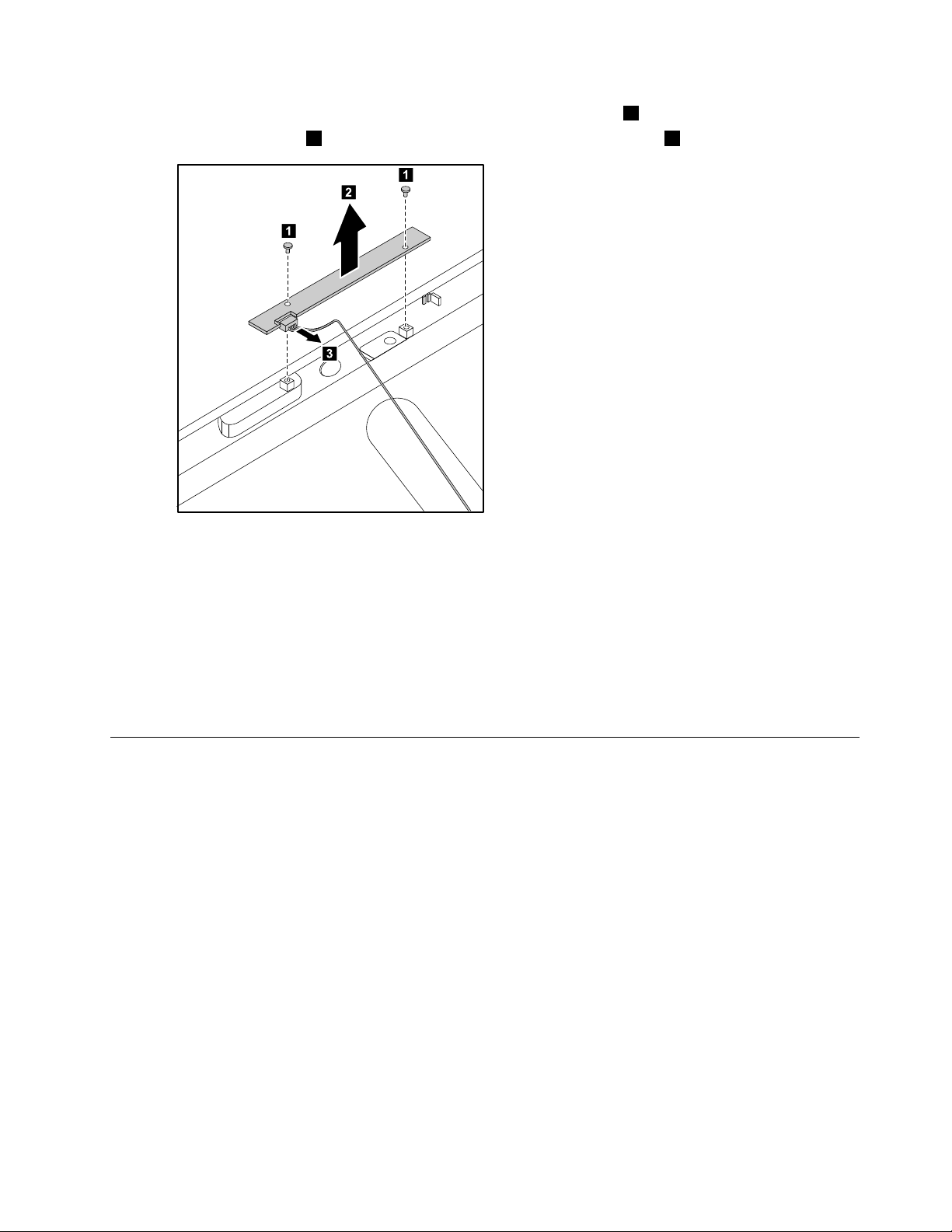
Step7.Removethe2screwsthatsecurethefrontfunctionboardtothefrontbezel.1
3
1
2
1
Step8.Disconnectthedatacablefromthefrontfunctionboard.2
Step9.Liftupthefrontfunctionboardtoremoveitfromthefrontbezel.3
Step10.Toinstallthenewfrontfunctionboard:
a.Connectthedatacabletothenewfrontfunctionboard.
b.Lineuptheholesinthenewfrontfunctionboardwiththemountingholesonthefrontbezel
andsecureitwiththe2screws.
Step11.ReattachtherearcovertotheLEDpanel.
Step12.Reattachthehingetothechassis.
Step13.Reconnectthescalarheadphoneinput,scalarandDVI/HDMIcablestothemotherboard.
Step14.Reattachthebasecoverandsecureitwiththescrews.
ReplacingtheLEDpanel
Note:T urnoffthecomputerandwait3to5minutestoletitcooldownbeforeremovingthebasecover.
Note:Itmaybehelpfultoplacethecomputerface-downonasoftatsurfaceforthisprocedure.Lenovo
recommendsthatyouuseablanket,towel,orothersoftclothtoprotectthecomputerscreenfromscratches
orotherdamage.
ToreplacetheLEDpanel:
Step1.Removeanymedia(disks,CDs,DVDs,ormemorycards)fromthedrives,shutdowntheoperating
system,andturnoffthecomputerandallattacheddevices.
Step2.Unplugallpowercordsfromelectricaloutlets.
Step3.Disconnectallcablesattachedtothecomputer.Thisincludespowercords,input/output(I/O)
Step4.Removethebasecover.Referto“Removingthebasecover”.
cables,andanyothercablesthatareconnectedtothecomputer.Referto“Leftandrightview”
and“Rearview”forhelpwithlocatingthevariousconnectors.
64IdeaCentreA530All-In-OnePCHardwareMaintenanceManual
Page 71
Step5.Removethehingefromthechassis.Referto“Removingthehingefromthechassis” .
Step6.Removetherearcover.Referto“Removingtherearcover”.
Step7.Removethescalarboard.Referto“Replacingthescalarboard” .
Step8.Removethetouchcontrolboard.Referto“Replacingthetouchcontrolboard” .
Step9.Removetheconverterboard.Referto“Replacingtheconverterboard” .
Step10.Removethepowerswitchboard.Referto“Replacingthepowerswitchboard” .
Step11.RemovetheBluetoothmodule.Referto“ReplacingtheBluetoothmodule” .
Step12.RemovetheWi-Ficard.Referto“ReplacingtheWi-Ficard” .
Step13.RemovetheWi-Fiantennacablefromthefrontbezel.
Step14.Removethecamera.Referto“Replacingthecamera” .
Step15.Removethefrontfunctionboard.Referto“Replacingthefrontfunctionboard” .
Step16.Removeallthecablesattachedtothemiddleframeandthefrontbezel.
Chapter8.Replacinghardware65
Page 72
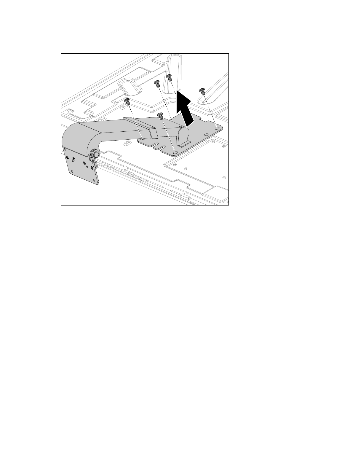
Step17.Removethe5screwsthatsecurethehingetothemiddleframeandsetthehingeaside.
Step18.ToinstallthenewtheLEDpanel:
a.Lineuptheholesonthehingewiththemountingholesonthenewmiddleframeandsecureit
with5screws.
b.AttachallthecablestothenewLEDpanelmiddleframeandfrontbezel.
c.AttachtheWi-Ficard,Bluetoothmodule,powerswitchboard,converterboard,touchcontrol
board,scalarboardandfrontfunctionboardtothenewLEDpanelmiddleframeandconnect
allthecablestothenewLEDpanel.
Step19.ReattachtherearcovertotheLEDpanel.
Step20.Reattachthehingetothechassis.
Step21.Reconnectthescalarheadphoneinput,scalarandDVI/HDMIcablestothemotherboard.
Step22.Reattachthebasecoverandsecureitwiththescrews.
66IdeaCentreA530All-In-OnePCHardwareMaintenanceManual
Page 73

Chapter9.Generalinformation
Thischapterprovidesgeneralinformationthatappliestoallcomputermodelscoveredbythismanual.
AdditionalServiceInformation
Thischapterprovidesadditionalinformationthattheservicerepresentativemightndhelpful.
Powermanagement
Powermanagementreducesthepowerconsumptionofcertaincomponentsofthecomputersuchasthe
systempowersupply,processor,harddiskdrives,andsomemonitors.
Advancedcongurationandpowerinterface(ACPI)BIOS
AsthiscomputerhasanACPIBIOSsystem,theoperatingsystemisallowedtocontrolthepower
managementfeaturesofthecomputerandthesettingsforAdvancedPowerManagement(APM)BIOSmode
isignored.NotalloperatingsystemssupportACPIBIOSmode.
AutomaticPower-Onfeatures
TheAutomaticPower-OnfeatureswithinthePowerManagementmenuallowyoutoenableanddisable
featuresthatturnonthecomputerautomatically.
•WakeUponAlarm:Youcanspecifyadateandtimeatwhichthecomputerwillbeturnedonautomatically.
Thiscanbeeitherasingleevent,adailyeventoraweeklyevent.
•WakeUponLAN:ThisfeatureallowsLANadaptercardtowaketheSystem.
©CopyrightLenovo2013
67
 Loading...