

Lenovo NetVista A40p, NetVista A40, A40 6830, A40 6831, A40 6840 User Manual
...
NetVista
™
User Guide
A40 Type 6830, 6831, 6840
A40p Type 6837, 6841, 6847
A40i Type 2251, 2271
IBM


NetVista
™
User Guide
A40 Type 6830, 6831, 6840
A40p Type 6837, 6841, 6847
A40i Type 2251, 2271
IBM

Note
Before using this information and the product it supports, be sure to read the “Safety Information” on page v and
“Appendix F. Notices and trademarks” on page 83.
First Edition (September 2000)
© Copyright International Business Machines Corporation 2000. All rights reserved.
US Government Users Restricted Rights – Use, duplication or disclosure restricted by GSA ADP Schedule Contract
with IBM Corp.

Contents
Safety Information ..........v
Lithium battery notice ...........vi
Modem safety information .........vi
Laser compliance statement .........vii
About this book ...........ix
How this book is organized .........ix
Information resources ...........x
Chapter 1. Overview .........1
Identifying your computer..........1
Desktop model computer .........2
Minitower model computer ........2
Microtower model computer ........3
Features ................3
Specifications ..............5
Physical specifications — desktop model ....6
Physical specifications — minitower model . . . 7
Physical specifications — microtower model . . . 8
Available options .............9
Tools required ..............9
Handling static-sensitive devices........9
Chapter 2. Installing external options 11
Locating the connectors on the front of your
computer ...............11
Locating the connectors on the rear of your
computer ...............14
High-performance video adapter ......18
High-performance audio adapter ......19
ADSL modem ............19
Home PNA network adapter .......19
Obtaining device drivers ..........20
Chapter 3. Installing internal options —
desktop model ...........21
Removing the cover ...........21
Locating components ...........22
Installing options on the system board .....22
Accessing the system board ........22
Identifying parts on the system board ....22
Installing memory ...........24
Installing adapters ...........26
Installing internal drives ..........27
Drive specifications...........28
Power and signal cables for internal drives . . . 28
Installing internal drives .........29
Installing a security U-bolt .........31
Replacing the cover and connecting the cables. . . 32
Chapter 4. Installing internal options —
minitower model ..........35
Removing the cover ...........35
Locating components ...........36
Installing options on the system board .....36
Accessing the system board ........36
Identifying parts on the system board ....36
Installing memory ...........37
Installing adapters ...........41
Installing internal drives ..........42
Drive specifications...........43
Power and signal cables for internal drives . . . 44
Installing internal drives in bays 1, 2, and 3 . . 46
Installing internal drives in bays 4, 5, 6, and 7 . . 47
Installing a security U-bolt .........50
Replacing the cover and connecting the cables. . . 51
Chapter 5. Installing internal options —
microtower model ..........53
Removing the cover ...........53
Locating components ...........54
Moving the power supply .........54
Installing options on the system board .....56
Accessing the system board ........56
Identifying parts on the system board ....56
Installing memory ...........58
Installing adapters ...........59
Installing internal drives ..........60
Drive specifications...........60
Power and signal cables for internal drives . . . 61
Installing internal drives .........62
Installing a security U-bolt .........64
Replacing the cover and connecting the cables. . . 65
Chapter 6. Updating the computer
configuration ............67
Verifying that an option is installed correctly . . . 68
Configuring PCI adapters .........68
Configuring startup devices .........69
Erasing a lost or forgotten password (clearing
CMOS) ................69
Appendix A. Using Enhanced Security 71
Appendix B. Changing the battery . . . 73
Appendix C. Updating System
Programs .............75
System programs ............75
Recovering from a POST/BIOS update failure . . . 75
Appendix D. System address maps . . 77
System memory map ...........77
I/O address map ............77
DMA I/O address map ..........79
© Copyright IBM Corp. 2000 iii

Appendix E. Interrupt request and
direct memory access channel
assignments ............81
Appendix F. Notices and trademarks . . 83
Trademarks ..............84
Index ...............85
User Guide
iv

Safety Information
DANGER
Electrical current from power, telephone, and communication cables is
hazardous.
To avoid a shock hazard:
v Do not connect or disconnect any cables or perform installation, maintenance,
or reconfiguration of this product during an electrical storm.
v Connect all power cords to a properly wired and grounded electrical outlet.
v Connect to properly wired outlets any equipment that will be attached to this
product.
v When possible, use one hand only to connect or disconnect signal cables.
v Never turn on any equipment when there is evidence of fire, water, or
structural damage.
v Disconnect the attached power cords, telecommunications systems, networks,
and modems before you open the device covers, unless instructed otherwise
in the installation and configuration procedures.
v Connect and disconnect cables as described in the following table when
installing, moving, or opening covers on this product or attached devices.
To connect:
1. Turn everything OFF.
2. First, attach all cables to devices.
3. Attach signal cables to connectors.
4. Attach power cords to outlet.
5. Turn device ON.
To disconnect:
1. Turn everything OFF.
2. First, remove power cords from outlet.
3. Remove signal cables from connectors.
4. Remove all cables from devices.
DANGER
Le courant électrique provenant de l’alimentation, du téléphone et des câbles de
transmission peut présenter un danger.
Pour éviter tout risque de choc électrique :
v Ne manipulez aucun câble et n’effectuez aucune opération d’installation,
d’entretien ou de reconfiguration de ce produit au cours d’un orage.
v Branchez tous les cordons d’alimentation sur un socle de prise de courant
correctement câblé et mis à la terre.
v Branchez sur des socles de prise de courant correctement câblés tout
équipement connecté à ce produit.
v Lorsque cela est possible, n’utilisez qu’une seule main pour connecter ou
déconnecter les câbles d’interface.;
v Ne mettez jamais un équipement sous tension en cas d’incendie ou
d’inondation, ou en présence de dommages matériels.
v Avant de retirer les carters de l’unité, mettez celle-ci hors tension et
déconnectez ses cordons d’alimentation, ainsi que les câbles qui la relient aux
© Copyright IBM Corp. 2000 v

réseaux, aux systèmes de té lécommunication et aux modems (sauf instruction
contraire mentionnée dans les procédures d’installation et de configuration).
v Lorsque vous installez, que vous déplacez, ou que vous manipulez le présent
produit ou des périphériques qui lui sont raccordés, reportez-vous aux
instructions ci-dessous pour connecter et déconnecter les différents cordons.
Connexion:
1. Mettez les unités hors tension.
2. Commencez par brancher tous les
cordons sur les unités.
3. Branchez les câbles d’interface sur des
connecteurs.
4. Branchez les cordons d’alimentation sur
des prises.
5. Mettez les unités sous tension.
Lithium battery notice
CAUTION:
Danger of explosion if battery is incorrectly replaced.
When replacing the battery, use only IBM Part Number 33F8354 or an equivalent
type battery recommended by the manufacturer. The battery contains lithium
and can explode if not properly used, handled, or disposed of.
Do not:
v Throw or immerse into water
v Heat to more than 100°C (212°F)
v Repair or disassemble
Déconnexion:
1. Mettez les unités hors tension.
2. Débranchez les cordons d’alimentation
des prises.
3. Débranchez les câbles d’interface des
connecteurs.
4. Débranchez tous les câbles des unités.
Dispose of the battery as required by local ordinances or regulations.
ATTENTION
Danger d’explosion en cas de remplacement incorrect de la batterie.
Remplacer uniquement par une batterie IBM de type ou d’un type équivalent
recommandé par le fabricant. La batterie contient du lithium et peut exploser en
cas de mauvaise utilisation, de mauvaise manipulation ou de mise au rebut
inappropriée.
Ne pas :
v Lancer ou plonger dans l’eau
v Chauffer à plus de 100°C (212°F)
v Réparer ou désassembler
Mettre au rebut les batteries usagées conformément aux règlements locaux.
Modem safety information
To reduce the risk of fire, electrical shock, or injury when using telephone
equipment, always follow basic safety precautions, such as:
v Never install telephone wiring during a lightning storm.
vi User Guide

v Never install telephone jacks in wet locations unless the jack is specifically
designed for wet locations.
v Never touch uninsulated telephone wires or terminals unless the telephone line
has been disconnected at the network interface.
v Use caution when installing or modifying telephone lines.
v Avoid using a telephone (other than a cordless type) during an electrical storm.
There may be a remote risk of electric shock from lightning.
v Do not use the telephone to report a gas leak in the vicinity of the leak.
Consignes de sécurité relatives au modem
Lors de l’utilisation de votre matériel téléphonique, il est important de respecter les
consignes ci-après afin de réduire les risques d’incendie, d’électrocution et d’autres
blessures :
v N’installez jamais de cordons téléphoniques durant un orage.
v Les prises téléphoniques ne doivent pas être installées dans des endroits
humides, excepté si le modèle a été conçu à cet effet.
v Ne touchez jamais un cordon téléphonique ou un terminal non isolé avant que
la ligne ait été déconnectée du réseau téléphonique.
v Soyez toujours prudent lorsque vous procédez à l’installation ou à la
modification de lignes téléphoniques.
v Si vous devez téléphoner pendant un orage, pour éviter tout risque de choc
électrique, utilisez toujours un téléphone sans fil.
v En cas de fuite de gaz, n’utilisez jamais un téléphone situé à proximité de la
fuite.
Laser compliance statement
Some IBM Personal Computer models are equipped from the factory with a
CD-ROM drive or a DVD-ROM drive. CD-ROM drives and DVD-ROM drives are
also sold separately as options. CD-ROM drives and DVD-ROM drives are laser
products. These drives are certified in the U.S. to conform to the requirements of
the Department of Health and Human Services 21 Code of Federal Regulations
(DHHS 21 CFR) Subchapter J for Class 1 laser products. Elsewhere, these drives
are certified to conform to the requirements of the International Electrotechnical
Commission (IEC) 825 and CENELEC EN 60 825 for Class 1 laser products.
When a CD-ROM drive or a DVD-ROM drive is installed, note the following
handling instructions.
CAUTION:
Use of controls or adjustments or performance of procedures other than those
specified herein might result in hazardous radiation exposure.
Removing the covers of the CD-ROM drive or DVD-ROM drive could result in
exposure to hazardous laser radiation. There are no serviceable parts inside the
CD-ROM drive or DVD-ROM drive. Do not remove the drive covers.
Some CD-ROM drives and DVD-ROM drives contain an embedded Class 3A or
Class 3B laser diode. Note the following statement.
Safety Information vii

DANGER
Laser radiation when open. Do not stare into the beam, do not view directly with optical
instruments, and avoid direct exposure to the beam.
DANGER:
Certains modèles d’ordinateurs personnels sont équipés d’origine d’une unité de
CD-ROM ou de DVD-ROM. Mais ces unités sont également vendues séparément
en tant qu’options. L’unité de CD-ROM/DVD-ROM est un appareil à laser. Aux
État-Unis, l’unité de CD-ROM/DVD-ROM est certifiée conforme aux normes
indiquées dans le sous-chapitre J du DHHS 21 CFR relatif aux produits à laser de
classe 1. Dans les autres pays, elle est certifiée être un produit à laser de classe 1
conforme aux normes CEI 825 et CENELEC EN 60 825.
Lorsqu’une unité de CD-ROM/DVD-ROM est installée, tenez compte des
remarques suivantes:
ATTENTION: Pour éviter tout risque d’exposition au rayon laser, respectez les
consignes de réglage et d’utilisation des commandes, ainsi que les procédures
décrites.
L’ouverture de l’unité de CD-ROM/DVD-ROM peut entraîner un risque
d’exposition au rayon laser. Pour toute intervention, faites appel à du personnel
qualifié.
Certaines unités de CD-ROM/DVD-ROM peuvent contenir une diode à laser de
classe 3A ou 3B. Tenez compte de la consigne qui suit:
DANGER
Rayonnement laser lorsque le carter est ouvert. Évitez toute exposition directe des yeux
au rayon laser. Évitez de regarder fixement le faisceau ou de l’observer à l’aide
d’instruments optiques.
viii User Guide

About this book
This publication provides instructions for installing most options into your
NetVista
to add to your computer.
™
computer. It also contains information to help you decide which options
How this book is organized
This book contains the following chapters and appendices:
v “Chapter 1. Overview“ provides an introduction to the options available for
your computer.
v “Chapter 2. Installing external options“ provides information to orient you to the
connectors on your computer and instructions for installing external options and
peripheral devices.
v “Chapter 3. Installing internal options — desktop model“ provides instructions
for removing the cover and installing hard disk drives, memory, and adapters in
the desktop model computer.
v “Chapter 4. Installing internal options — minitower model“ provides
instructions for removing the cover and installing hard disk drives, memory, and
adapters in the minitower model computer.
v “Chapter 5. Installing internal options — microtower model“ provides
instructions for removing the cover and installing hard disk drives, memory, and
adapters in the microtower model computer.
v “Chapter 6. Updating the computer configuration“ provides instructions for
updating the computer configuration.
v “Appendix A. Using Enhanced Security“ provides information for A40p model
computers that you should know before you remove the cover or components.
v “Appendix B. Changing the battery“ provides instructions to help you change
the battery if you need to.
v “Appendix C. Updating System Programs“ provides instructions to help you if
you ever experience a POST/BIOS update failure.
v “Appendix D. System address maps“ provides information for programmers
describing the address maps of the computer.
v “Appendix E. Interrupt request and direct memory access channel assignments“
provides information about the interrupt and direct memory access channel
assignments.
v “Appendix F. Notices and trademarks“ contains notice and trademark
information.
© Copyright IBM Corp. 2000 ix

Information resources
This publication is intended to provide the necessary instructions for installing
most options into your NetVista computer. This publication also includes an
overview of computer features, locating connectors, and updating configuration
settings.
Access IBM on your desktop provides a link to more information about your
computer.
For those with Internet access, the most up-to-date manuals for your computer are
available from the World Wide Web. To access this information, point your browser
to:
http://www.ibm.com/pc/support
Type your machine type and model number in the Quick Path field and click Go.
x User Guide

Chapter 1. Overview
Adding hardware options to your NetVista computer is an easy way to increase its
capabilities. Instructions for installing external and internal options are included in
this publication. When adding an option, use these instructions along with the
instructions that come with the option.
This chapter provides a brief introduction to the options and features that are
available for your computer. Also, important information about required tools,
electrical safety, and static-sensitive devices is included.
Important
Before you install any option, read “Safety Information” on page v. These
precautions and guidelines will help you work safely.
See Access IBM for general information about the use, operation, and maintenance
of your computer. Access IBM also contains information to help you solve
problems and get repair service or other technical assistance.
Identifying your computer
To properly install options, you will need to know the model of your computer.
The best way to identify your computer is by the machine type/model number.
The machine type/model number indicates the various features of the computer,
such as the type of microprocessor or the number of drive bays. You can find this
number on the small label on the front of your computer. An example of the
machine type/model number is 6840-110.
The information in this publication is for the desktop, minitower, and microtower
model computers.
v The desktop type is 6837.
v The minitower types are 2271, 6840, 6841, and 6847.
v The microtower types are 2251, 6830 and 6831.
When it is necessary to distinguish between the models you will see references to
the model type. When the model is not specified, the information applies to all.
See the following pages for descriptions of the three basic types.
© Copyright IBM Corp. 2000 1
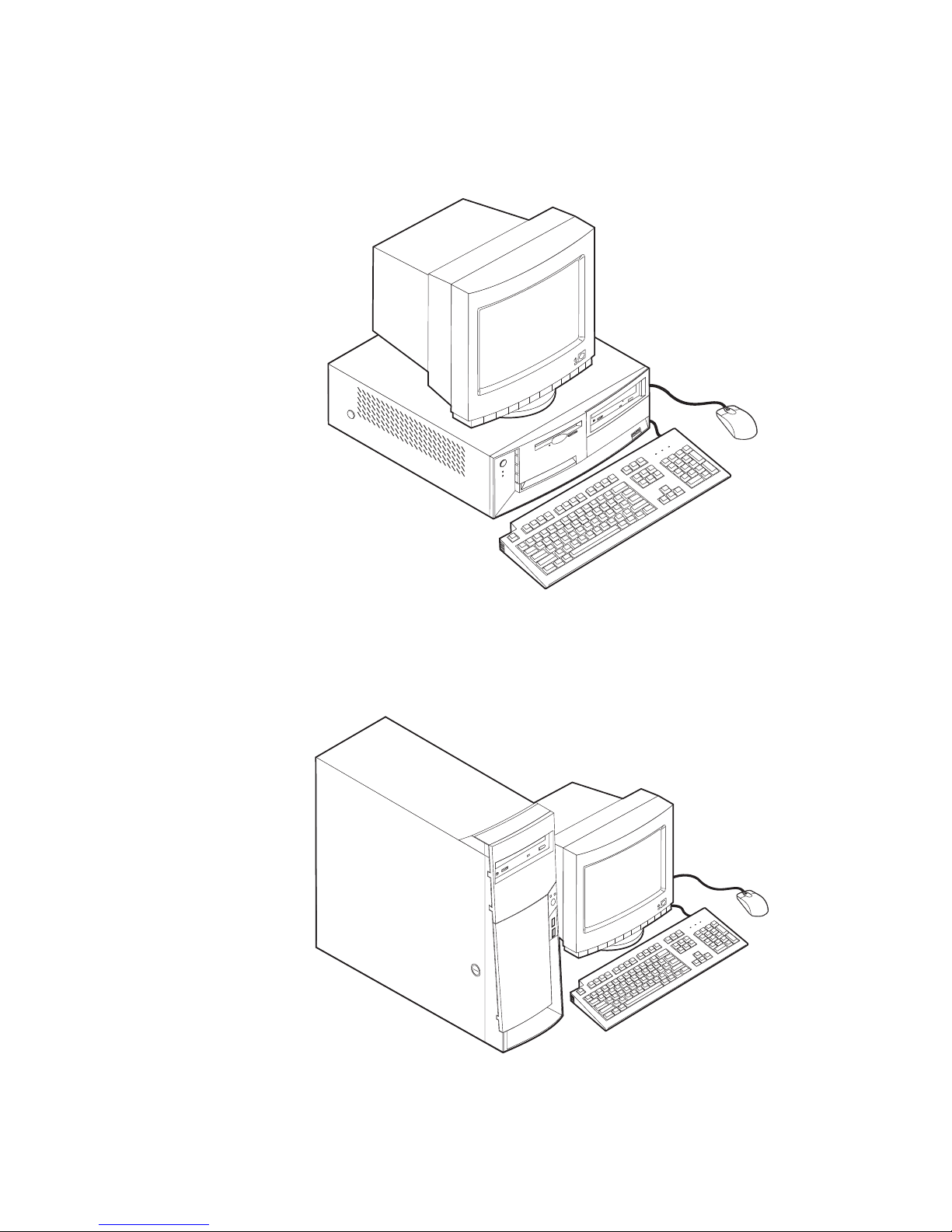
Desktop model computer
Desktop models come with a diskette drive and a hard disk drive. Some models
come with a CD-ROM drive. The power button is located on the left side of the
computer as you are facing it.
Minitower model computer
Minitower models come with a diskette drive and a hard disk drive. Some models
come with a CD drive or DVD drive. The power button is located on the right side
of the computer as you are facing it.
2 User Guide
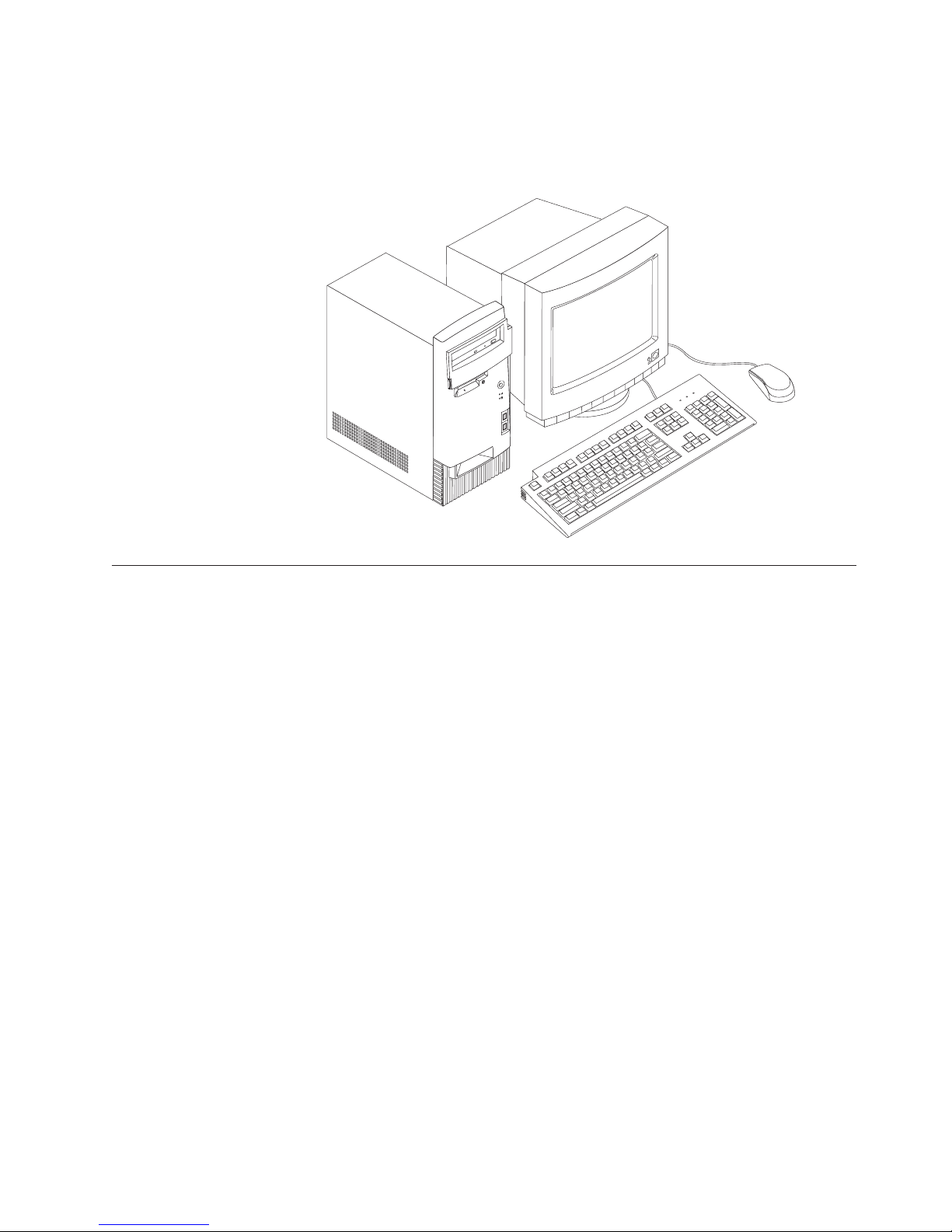
Microtower model computer
Microtower models come with a diskette drive and a hard disk drive. Some
models come with a CD drive or DVD drive. The power button is located on the
right side of the computer as you are facing it.
Features
This section provides an overview of the computer features, preinstalled software,
and specifications.
Not all models come with all features summarized here.
Microprocessor
®
Pentium™III microprocessor with 256 KB of internal L2 cache memory
Intel
Memory
v Support for Rambus inline memory modules (RIMMs) or dual inline memory
modules (DIMMs), depending on the model
– 3.3 V, synchronous, 168-pin, unbuffered, 133 MHz nonparity synchronous
dynamic random access memory (SDRAM) or nonparity Rambus dynamic
random access memory (RDRAM), depending on the model
– 64 MB, 128 MB, and 256 MB unbuffered nonparity DIMMs or RIMMs for a
maximum of 512 MB
– DIMM or RIMM heights of 38.1 mm (1.5 inches)
v 512 KB flash memory for system programs
Internal drives
v 3.5-inch, 1.44 MB diskette drive
v Internal hard disk drive
v EIDE CD drive or DVD drive (some models)
Video controller
v Dynamic video memory technology
Chapter 1. Overview 3

v Accelerated graphics port (AGP) adapter (some models)
Audio subsystem
16-integrated Sound Blaster Pro compatible audio subsystem
Connectivity
v 10/100 Mbps Ethernet adapter that supports Wake on LAN
®
(some models)
v Modem (some models)
System management features
v Remote Program Load (RPL) and Dynamic Host Configuration Protocol (DHCP)
v Wake on LAN (requires Wake on LAN-supported network adapter)
v Wake on Ring (in the Configuration/Setup Utility program, this feature is called
Serial Port Ring Detect for an external modem and Modem Ring Detect for an
internal modem)
v Wake on Alarm
v Remote Administration (the ability to update POST and BIOS over the network)
v Automatic power-on startup
v System Management (SM) BIOS and SM software
v Ability to store POST hardware test results
Input/output features
v 25-pin, ECP/EPP parallel port
v One or two 9-pin serial ports
v Four 4-pin, USB ports
v PS/2 mouse port
v PS/2 keyboard port
v 15-pin monitor port
v Three audio connectors (line/headphone out, line in, and microphone)
v Joystick/MIDI connectors (some models)
Expansion
v Drive bays:
– Desktop model: 4
– Minitower model: 7
– Microtower model: 4
v PCI expansion slots
– Desktop model: 3
– Minitower model: 5
– Microtower model: 3
v One AGP expansion slot
Power
v 155 W or 200 W power supply with manual voltage selection switch
v Automatic 50/60 Hz input frequency switching
v Advanced Power Management support
v Advance Configuration and Power Interface (ACPI) support
4 User Guide

Security features
v Power-on and administrator passwords
v Cover keylock
v Support for the addition of a U-bolt and lockable cable
v Startup sequence control
v Startup without diskette drive, keyboard, or mouse
v Unattended start mode
v Diskette and hard disk I/O control
v Serial and parallel port I/O control
v Security profile by device
IBM preinstalled software
Your computer might come with preinstalled software. If so, an operating system,
device drivers to support built-in features, and other support programs are
included.
Specifications
Operating systems (supported)
v Microsoft
®
Windows®2000 Professional
v Microsoft Windows NT®Workstation Version 4.0 with Service Pack 6
v Microsoft Windows 98 SE
v Microsoft Windows Millennium Edition (Me)
v Novell NetWare Versions 3.2, 4.11, 5.0
Operating systems (tested for compatibility)
1
v Microsoft Windows 95
v DOS 2000
v SCO OpenServer 5.0.2 and later
v IBM OS/2®Warp Connect 3.0
v IBM OS/2 Warp 4.0
v IBM OS/2 LAN Server 3.0 and 4.0
v Linux: Red hat, Caldera, S.U.S.E., and Pacific High Tech
v Sun Solaris 2.5.1 or later
This section lists the physical specifications for the NetVista computer. The
NetVista desktop and microtower models have three 32-bit PCI expansion slots,
one AGP slot, and four drive bays. The NetVista minitower model computer has
five 32-bit PCI expansion slots, one AGP slot, and seven drive bays.
Note: The computer is classified as a Class A or Class B digital device. See the
Quick Reference for further information about this classification.
1. The operating systems listed here are being tested for compatibility at the time this publication goes to press. Additional
operating systems might be identified by IBM as compatible with your computer following the publication of this booklet.
Corrections and additions to this list are subject to change. To determine if an operating system has been tested for compatibility,
check the Web site of the operating system vendor.
Chapter 1. Overview
5

Physical specifications — desktop model
Dimensions
Height: 140 mm (5.5 in.)
Width: 425 mm (16.7 in.)
Depth: 425 mm (16.7 in.)
Weight
Minimum configuration as shipped: 9.4 kg (20 lb)
Maximum configuration: 11.3 kg (25.0 lb)
Environment
Air temperature:
System on: 10° to 35° C (50° to 95° F)
System off: 10° to 43° C (50° to 110° F)
Maximum altitude: 2134 m (7000 ft)
Note: The maximum altitude, 2134 m (7000 ft), is
the maximum altitude at which the specified air
temperatures apply. At higher altitudes, the
maximum air temperatures are lower than those
specified.
Humidity:
System on: 8% to 80%
System off: 8% to 80%
Electrical input
Input voltage:
Low range:
Minimum: 90 V ac
Maximum: 137 V ac
Input frequency range: 57–63 Hz
Voltage switch setting: 115 V ac
High range:
Minimum: 180 V ac
Maximum: 265 V ac
Input frequency range: 47–53 Hz
Voltage switch setting: 230 V ac
Input kilovolt-amperes (kVA) (approximate):
Minimum configuration as shipped: 0.08 kVA
Maximum configuration: 0.30 kVA
Heat output (approximate) in British thermal units (Btu)
per hour:
Minimum configuration: 240 Btu/hr. (75 watts)
Maximum configuration: 705 Btu/hr. (207 watts)
Airflow
Approximately 0.5 cubic meters per minute (18 cubic
feet per minute) maximum
Acoustical noise-emission values
Average sound-pressure levels:
At operator position:
Idle: 38 dBA
Operating: 43 dBA
At bystander position - 1 meter (3.3 ft):
Idle: 33 dBA
Operating: 37 dBA
Declared (upper limit) sound-power levels:
Idle: 4.8 bels
Operating: 5.1 bels
Note: These levels were measured in controlled
acoustical environments according to the procedures
specified by the American National Standards
Institute (ANSI) S12.10 and ISO 7779 and are reported
in accordance with ISO 9296. Actual sound-pressure
levels in a given location might exceed the average
values stated because of room reflections and other
nearby noise sources. The declared sound-power
levels indicate an upper limit, below which a large
number of computers will operate.
Note: Power consumption and heat output vary
depending on the number and type of optional
features installed and the power-management
optional features in use.
6 User Guide

Physical specifications — minitower model
Dimensions
Height: 165 mm (6.5 in.)
Width: 445 mm (17.5 in.)
Depth: 499 mm (19.6 in.)
Weight
Minimum configuration as shipped: 14.0 kg (30 lb)
Maximum configuration: 17.3 kg (38.0 lb)
Environment
Air temperature:
System on: 10° to 35° C (50° to 95° F)
System off: 10° to 43° C (50° to 110° F)
Maximum altitude: 2134 m (7000 ft)
Note: The maximum altitude, 2134 m (7000 ft), is
the maximum altitude at which the specified air
temperatures apply. At higher altitudes, the
maximum air temperatures are lower than those
specified.
Humidity:
System on: 8% to 80%
System off: 8% to 80%
Electrical input
Input voltage:
Low range:
Minimum: 90 V ac
Maximum: 137 V ac
Input frequency range: 57–63 Hz
Voltage switch setting: 115 V ac
High range:
Minimum: 180 V ac
Maximum: 265 V ac
Input frequency range: 47–53 Hz
Voltage switch setting: 230 V ac
Input kilovolt-amperes (kVA) (approximate):
Minimum configuration as shipped: 0.08 kVA
Maximum configuration: 0.3 kVA
Heat output (approximate) in British thermal units (Btu)
per hour:
Minimum configuration: 240 Btu/hr. (75 watts)
Maximum configuration: 940 Btu/hr. (275 watts)
Airflow
Approximately 0.34 cubic meters per minute (12 cubic
feet per minute) maximum
Acoustical noise-emission values
Average sound-pressure levels:
At operator position:
Idle: 38 dBA
Operating: 43 dBA
At bystander position - 1 meter (3.3 ft):
Idle: 33 dBA
Operating: 37 dBA
Declared (upper limit) sound-power levels:
Idle: 4.8 bels
Operating: 5.1 bels
Note: These levels were measured in controlled
acoustical environments according to the procedures
specified by the American National Standards
Institute (ANSI) S12.10 and ISO 7779 and are reported
in accordance with ISO 9296. Actual sound-pressure
levels in a given location might exceed the average
values stated because of room reflections and other
nearby noise sources. The declared sound-power
levels indicate an upper limit, below which a large
number of computers will operate.
Note: Power consumption and heat output vary
depending on the number and type of optional
features installed and the power-management
optional features in use.
Chapter 1. Overview 7

Physical specifications — microtower model
Dimensions
Height: 140 mm (5.5 in.)
Width: 425 mm (16.7 in.)
Depth: 425 mm (16.7 in.)
Weight
Minimum configuration as shipped: 9.4 kg (20 lb)
Maximum configuration: 11.3 kg (25.0 lb)
Environment
Air temperature:
System on: 10° to 35° C (50° to 95° F)
System off: 10° to 43° C (50° to 110° F)
Maximum altitude: 2134 m (7000 ft)
Note: The maximum altitude, 2134 m (7000 ft), is
the maximum altitude at which the specified air
temperatures apply. At higher altitudes, the
maximum air temperatures are lower than those
specified.
Humidity:
System on: 8% to 80%
System off: 8% to 80%
Electrical input
Input voltage:
Low range:
Minimum: 90 V ac
Maximum: 137 V ac
Input frequency range: 57–63 Hz
Voltage switch setting: 115 V ac
High range:
Minimum: 180 V ac
Maximum: 265 V ac
Input frequency range: 47–53 Hz
Voltage switch setting: 230 V ac
Input kilovolt-amperes (kVA) (approximate):
Minimum configuration as shipped: 0.08 kVA
Maximum configuration: 0.3 kVA
Heat output (approximate in British thermal units (Btu)
per hour:
Minimum configuration: 240 Btu/hr. (75 watts)
Maximum configuration: 705 Btu/hr. (207 watts)
Airflow
Approximately 0.5 cubic meters per minute (18 cubic
feet per minute) maximum
Acoustical noise-emission values
Average sound-pressure levels:
At operator position:
Idle: 38 dBA
Operating: 43 dBA
At bystander position - 1 meter (3.3 ft):
Idle: 33 dBA
Operating: 37 dBA
Declared (upper limit) sound-power levels:
Idle: 4.8 bels
Operating: 5.1 bels
Note: These levels were measured in controlled
acoustical environments according to the procedures
specified by the American National Standards
Institute (ANSI) S12.10 and ISO 7779 and are reported
in accordance with ISO 9296. Actual sound-pressure
levels in a given location might exceed the average
values stated because of room reflections and other
nearby noise sources. The declared sound-power
levels indicate an upper limit, below which a large
number of computers will operate.
Note: Power consumption and heat output vary
depending on the number and type of optional
features installed and the power-management
optional features in use.
8 User Guide

Available options
The following are some available options:
v External options
v Internal options
– Parallel port devices, such as printers and external drives
– Serial port devices, such as external modems and digital cameras
– Audio devices, such as external speakers for the sound system
– USB devices, such as printers and scanners
– Security U-bolt
– Monitor
– System memory
- Dual in-line memory modules (DIMMs)
- Rambus in-line memory modules (RIMMs)
– Adapters
- Peripheral component interconnect (PCI) adapters
- Accelerated graphics port (AGP) adapters
– Internal drives
- CD drive or DVD drive
- Hard disk
- Diskette drives and other removable media drives
For the latest information about available options, see the following World Wide
Web pages:
v http://www.ibm.com/pc/us/options/
v http://www.ibm.com/pc/support/
You can also obtain information by calling the following telephone numbers:
v Within the United States, call 1-800-IBM-2YOU (1-800-426-2968), your IBM
reseller, or IBM marketing representative.
v Within Canada, call 1-800-565-3344 or 1-800-465-7999.
v Outside the United States and Canada, contact your IBM reseller or IBM
marketing representative.
Tools required
To install some options in your computer, you might need a flat-blade screwdriver.
Additional tools might be needed for certain options. See the instructions that
come with the option.
Handling static-sensitive devices
Static electricity, although harmless to you, can seriously damage computer
components and options.
When you add an option, do not open the static-protective package containing the
option until you are instructed to do so.
When you handle options and other computer components, take these precautions
to avoid static electricity damage:
Chapter 1. Overview 9

v Limit your movement. Movement can cause static electricity to build up around
you.
v Always handle components carefully. Handle adapters and memory modules by
the edges. Never touch any exposed circuitry.
v Prevent others from touching components.
v When you install a new option, touch the static-protective package containing
the option to a metal expansion-slot cover or other unpainted metal surface on
the computer for at least two seconds. This reduces static electricity in the
package and your body.
v When possible, remove the option and install it directly in the computer without
setting the option down. When this is not possible, place the static-protective
package that the option came in on a smooth, level surface and place the option
on it.
v Do not place the option on the computer cover or other metal surface.
10 User Guide
Chapter 2. Installing external options
This chapter shows the various external connectors on your computer to which
you can attach external options, such as external speakers, a printer, or a scanner.
For some external options, you must install additional software in addition to
making the physical connection. When adding an external option, use the
information in this chapter to identify the required connector, and then use the
instructions that come with the option to help you make the connection and install
any software or drivers required for the option.
Important
Before you install or remove any option, read “Safety Information” on page v.
These precautions and guidelines will help you work safely.
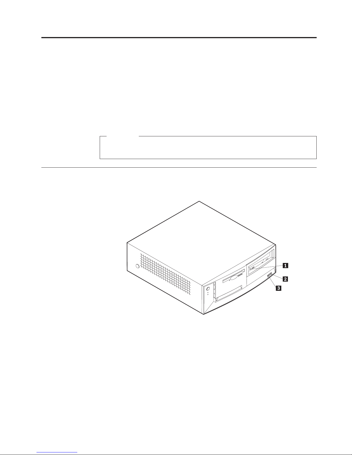
Locating the connectors on the front of your computer
The following illustration shows the location of the connectors on the front of the
desktop computer.
«1¬ CD-ROM headphone connector
«2¬ Front USB connector 1
«3¬ Front USB connector 2
© Copyright IBM Corp. 2000 11

The following illustration shows the location of the connectors on the front of the
minitower computer.
«1¬ CD-ROM headphone connector
«2¬ Front USB connector 1
«3¬ Front USB connector 2
12 User Guide
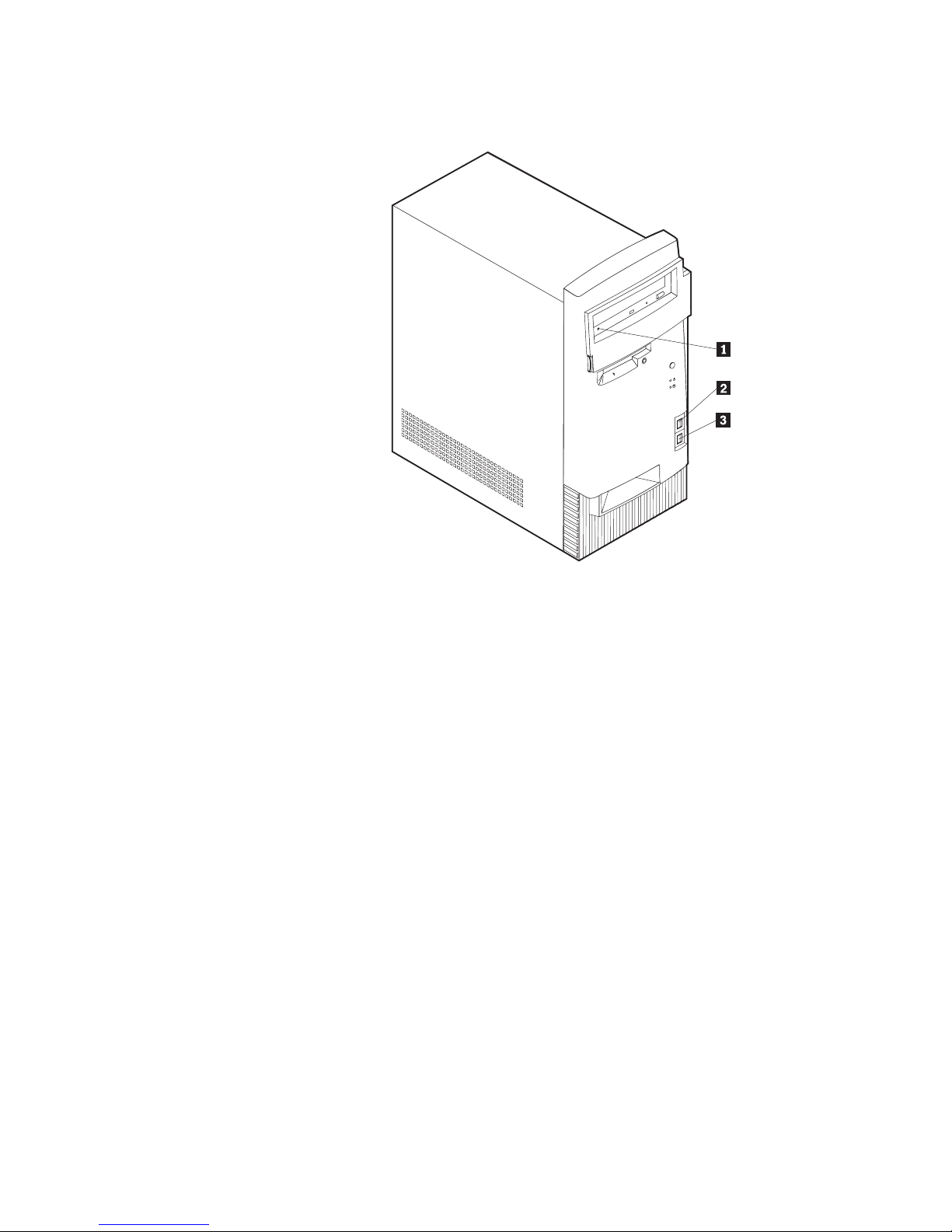
The following illustration shows the location of the connectors on the front of the
microtower computer.
«1¬ CD-ROM headphone connector
«2¬ Front USB connector 1
«3¬ Front USB connector 2
Chapter 2. Installing external options 13
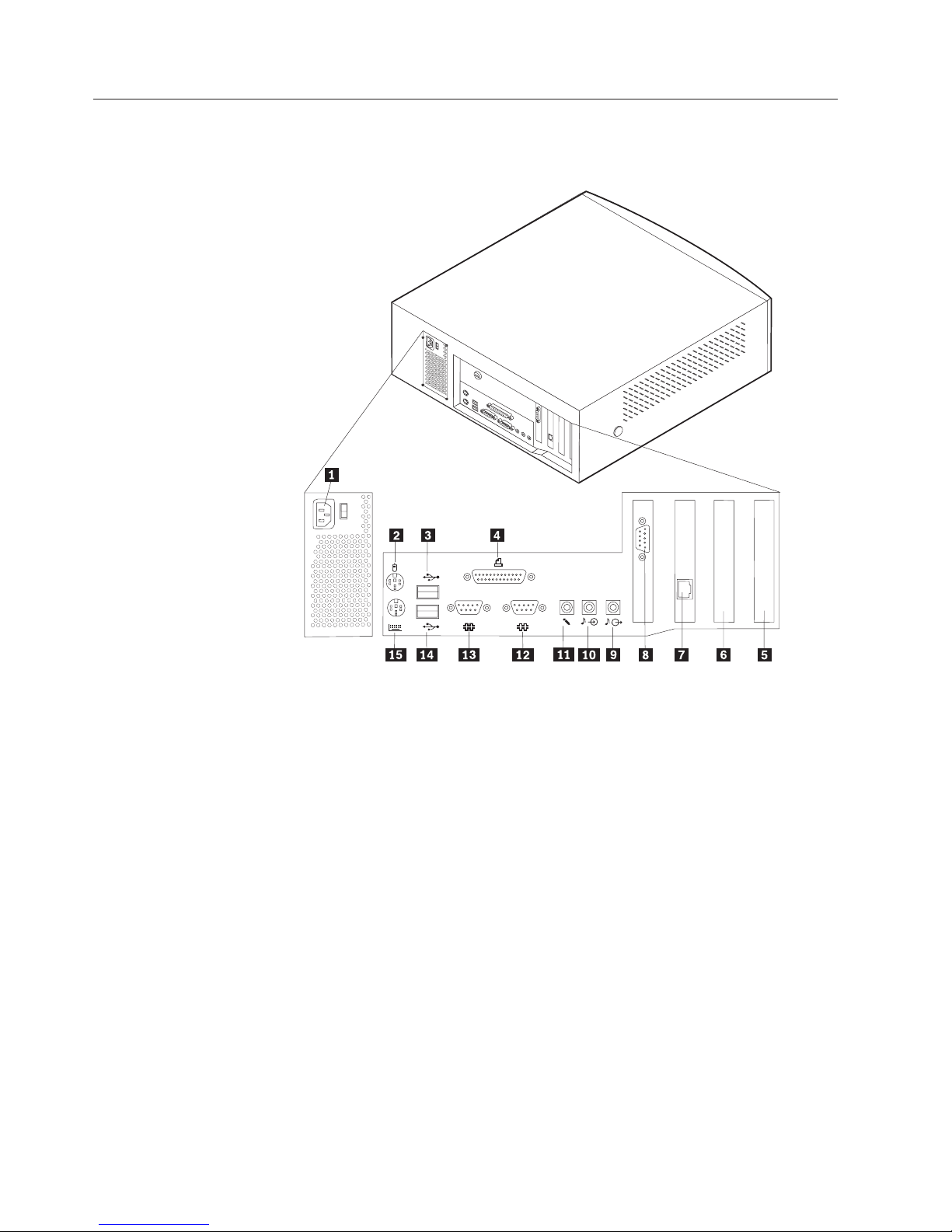
Locating the connectors on the rear of your computer
The following illustration shows the location of the connectors on the back of the
desktop model computer. You might not have all of the connectors shown here.
2
1
«1¬ Power connector «9¬ Audio out connector
«2¬ Mouse connector «10¬ Audio in connector
«3¬ USB connector 2 «11¬ Microphone connector
«4¬ Parallel connector «12¬ Serial connector 2
«5¬ PCI connector 1 «13¬ Serial connector 1
«6¬ PCI connector 2 «14¬ USB connector 1
«7¬ Ethernet connector «15¬ Keyboard connector
«8¬ Monitor connector (AGP adapter)
Note: The connectors on the rear of the computer have color-coded icons. Icons
will help you to determine where to connect the proper cables on your
computer.
14 User Guide
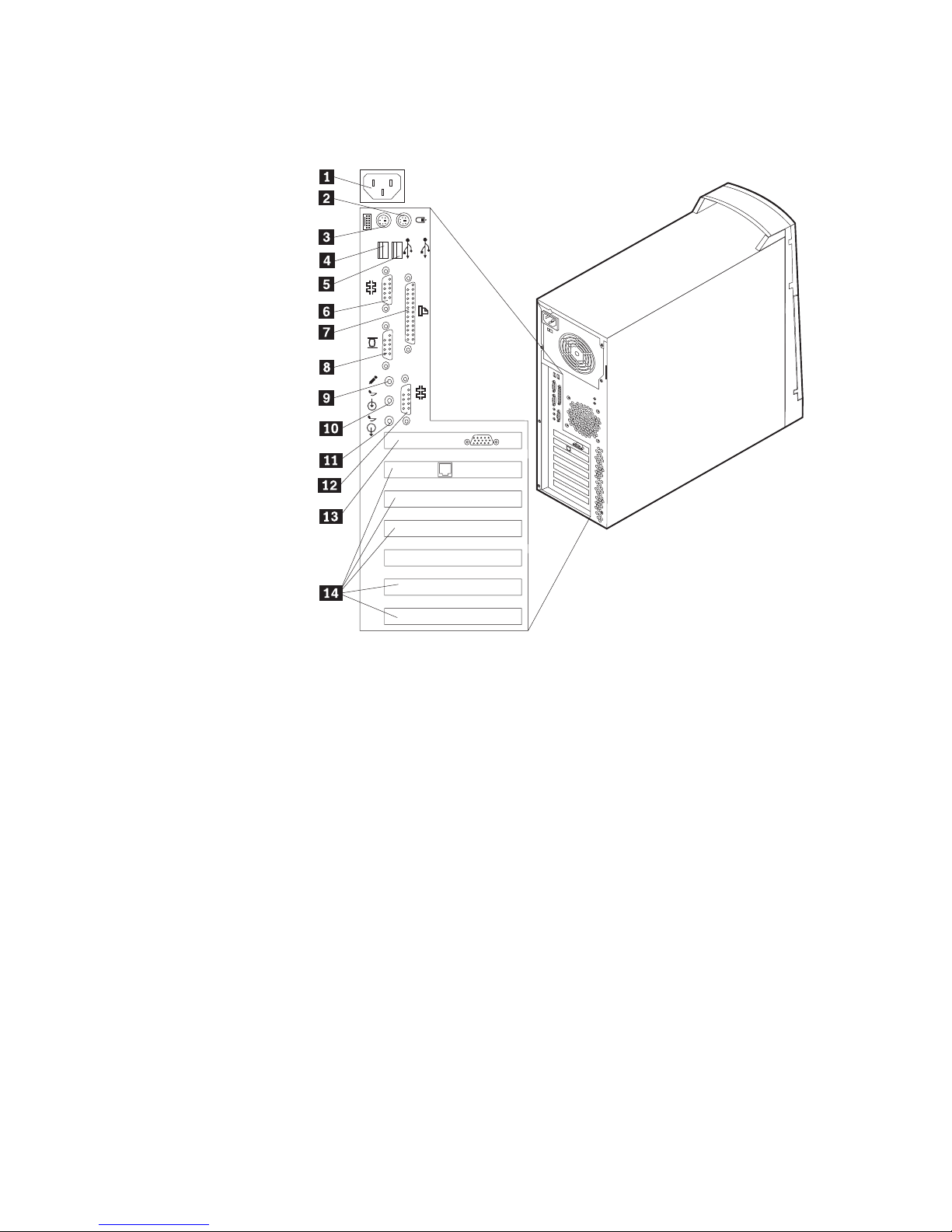
The following illustration shows the location of the connectors on the back of the
minitower model types 2271, 6840, and 6841. You might not have all of the
connectors shown here.
2
1
1
2
«1¬ Power connector «8¬ Monitor connector
«2¬ Mouse connector «9¬ Microphone connector
«3¬ Keyboard connector «10¬ Audio in connector
«4¬ USB connector 1 «11¬ Audio out connector
«5¬ USB connector 2 «12¬ Serial connector 2
«6¬ Serial connector 1 «13¬ AGP monitor connector
«7¬ Parallel connector «14¬ PCI slots
Note: The connectors on the rear of the computer have color-coded icons. Icons
will help you to determine where to connect the proper cables on your
computer.
Chapter 2. Installing external options 15
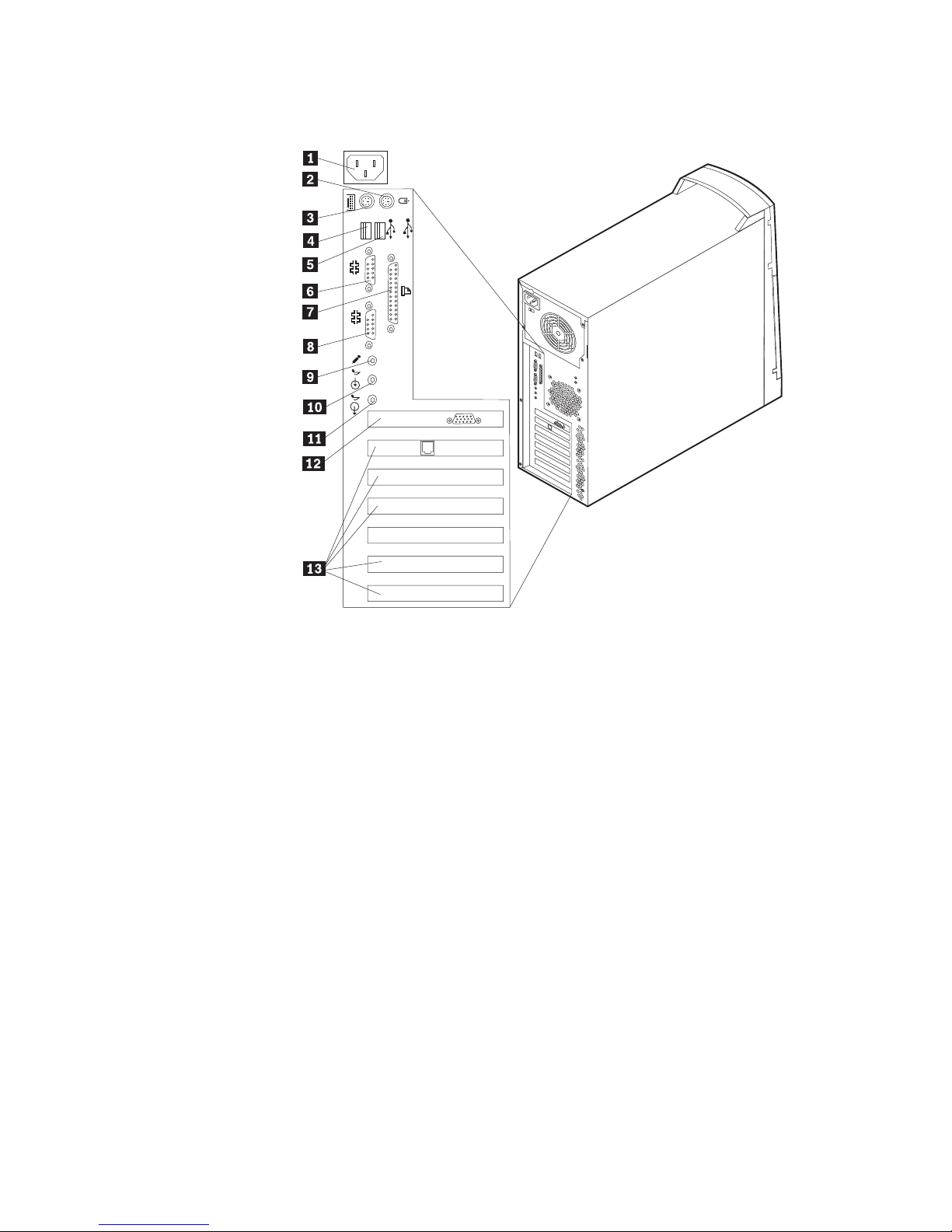
The following illustration shows the location of the connectors on the back of the
minitower model type 6847. You might not have all of the connectors shown here.
2
1
1
2
«1¬ Power connector «8¬ Serial connector 2
«2¬ Mouse connector «9¬ Microphone connector
«3¬ Keyboard connector «10¬ Audio in connector
«4¬ USB connector 1 «11¬ Audio out connector
«5¬ USB connector 2 «12¬ AGP monitor connector
«6¬ Serial connector 1 «13¬ PCI slots
«7¬ Parallel connector
Note: The connectors on the rear of the computer have color-coded icons. Icons
will help you to determine where to connect the proper cables on your
computer.
16 User Guide
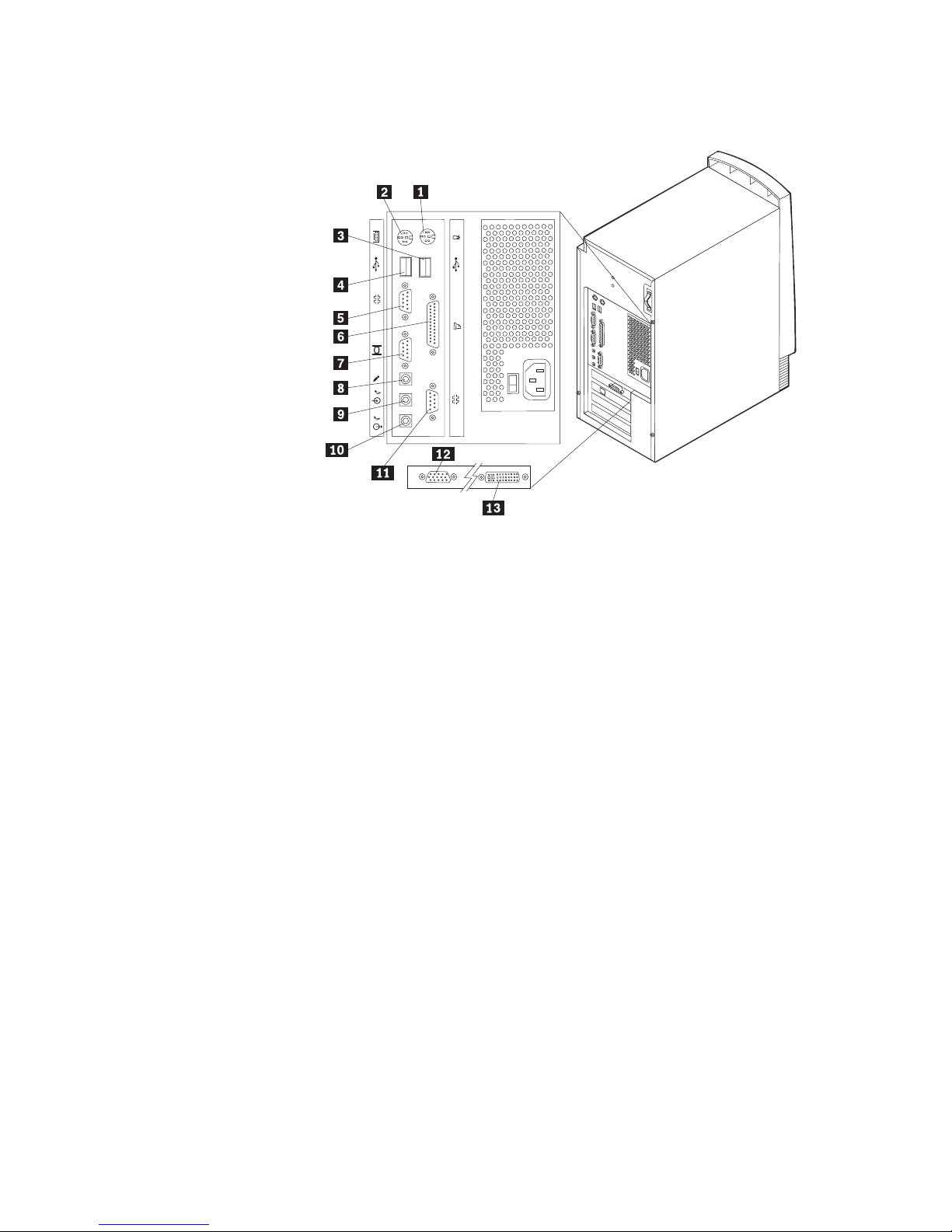
The following illustration shows the location of the connectors on the back of the
microtower model computer. You might not have all of the connectors shown here.
1
1
2
2
«1¬ Mouse connector «8¬ Microphone connector
«2¬ Keyboard connector «9¬ Audio in connector
«3¬ USB connector 2 «10¬ Audio out connector
«4¬ USB connector 1 «11¬ Serial connector 2
«5¬ Serial connector 1 «12¬ SVGA Monitor connector (AGP adapter) (some models only)
«6¬ Parallel connector «13¬ DVI Monitor connector (AGP adapter) (some models only)
«7¬ Monitor connector
Note: The connectors on the rear of the computer have color-coded icons. Icons
will help you to determine where to connect the proper cables on your
computer.
Chapter 2. Installing external options 17
Connector Description
Mouse connector Used to attach a mouse, trackball, or other pointing device that uses a mouse
connector.
Keyboard connector Used to attach a keyboard that uses a keyboard connector.
USB connectors Used to attach a device that requires a Universal Serial Bus (USB) connection, such as
a USB scanner or USB printer. If you have more than four USB devices, you can
purchase a USB hub, which you can use to connect additional USB devices.
Serial connectors Used to attach an external modem, serial printer, or other device that uses a 9-pin
serial connector.
Parallel connector Used to attach a parallel printer, parallel scanner, or any other device that requires a
25-pin parallel connection.
Monitor connector Used to attach a monitor. Some models might have two monitor connectors. There is
one on the system board and some models have an AGP adapter that provides a
monitor connection. The AGP adapter might support a DVI monitor, a SVGA, or
both.
Microphone connector Used to attach a microphone to your computer when you want to record voice or
other sounds on the hard disk if you use speech-recognition software.
Audio line-in connector Used to receive audio signals from an external audio device, such as a stereo system.
When you attach an external audio device, a cable is connected between the audio
line-out connector of the device and the audio line-in connector of the computer.
Audio line-out connector Used to send audio signals from the computer to external devices, such as powered
stereo speakers (speakers with built-in amplifiers), headphones, multimedia
keyboards, or the audio line-in connector on a stereo system or other external
recording device.
Note: The internal speaker in your computer is disabled when external speakers are
connected to the audio line-out connector on your computer.
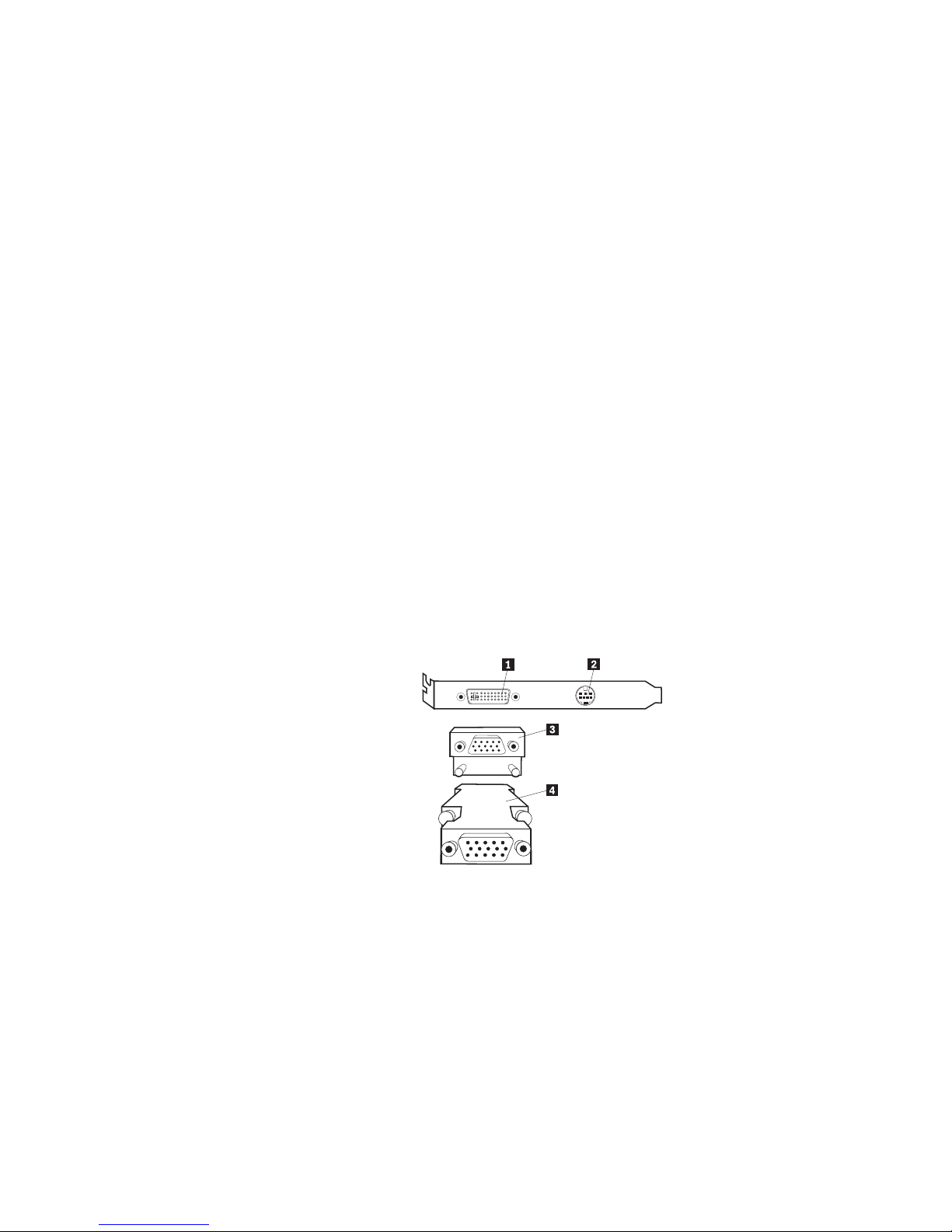
High-performance video adapter
Some models come with a high-performance AGP video adapter.
Connector Description
«1¬ Digital video interface (DVI ) connector Used to attach a digital monitor. This connector provides the signals
necessary to support the Display Power Management Signaling (DPMS)
standard.
«2¬ S-Video connector Used to attach a television set that has a S-Video connector. The
S-Video cable (required to connect the television set to the adapter) is a
separately purchased item.
«3¬ SVGA monitor converter Used to attach an analog SVGA monitor to the AGP DVI connector.
This SVGA converter is used for desktop models.
«4¬ SVGA monitor converter Used to attach an analog SVGA monitor to the AGP DVI connector.
This SVGA converter is used for minitower and microtower models.
18 User Guide
 Loading...