

Page 1
LENNOX HEARTH PRODUCTS
INSTALLATION AND OPERATING
INSTRUCTIONS
TM
REFLECTIONS
36" Electric Fireplace
P/N 850,019M REV. B 04/2007
MODELS
LSE-36R
This installation manual will enable you to obtain a safe, efficient and
dependable installation of your electric fireplace. Please read and understand these instructions before beginning your installation.
Do not alter or modify the fireplace or its components under any
circumstances. Any modification or alteration of the fireplace system,
including but not limited to the fireplace and accessories, may void the
warranty, listings and approvals of this system and could result in an
unsafe and potentially dangerous installation.
RETAIN THESE INSTRUCTIONS
FOR FUTURE REFERENCE
IMPORTANT! TO ASSURE PROPER ALIGNMENT OF GLASS DOORS:
INSTALL THIS FIREPLACE IN A SQUARE AND PLUMB CONDITION,
USING SHIMS AS NECESSARY AT SIDES AND/OR BOTTOM.
INSTALLER: DO NOT DISCARD THIS MANUAL
PLEASE LEAVE FOR THE HOMEOWNER
FOR YOUR SAFETY
DO NOT STORE OR USE GASOLINE OR OTHER FLAMMABLE
VAPORS AND LIQUIDS IN THE VICINITY OF THIS OR ANY OTHER
APPLIANCE
LENNOXTM ELECTRIC FIREPLACES ARE DESIGNED FOR USE AS
A DECORATIVE APPLIANCE AND/OR AS A SUPPLEMENTAL
HEATER. THEY ARE NOT INTENDED FOR CONTINUOUS USE AS
A PRIMARY HEAT SOURCE.
OTL Report No. 116-F-12-2
NOTE: DIAGRAMS & ILLUSTRATIONS NOT TO SCALE.
1
Page 2

CONGRATULATIONS!
In selecting this DAVE LENNOX Signature™ Collection electric fireplace, you have
chosen the finest and most dependable fireplace found anywhere. A beautiful and
prestigious addition to the finest homes. Welcome to a Family of hundreds of
thousands of satisfied LENNOX Fireplace Owners.
Please read and carefully follow all of the instructions found in this manual. Please pay
special attention to the safety instructions provided in this manual. The Homeowner's
Care and Operation Instructions included here will assure that you have many years of
dependable and enjoyable service from your LENNOX product.
TABLE OF CONTENTS
Tools Required ................................ page 2
Precautions ..................................... page 2
General Information......................... page 2
Locating the Fireplace...................... page 3
Unpacking the Unit .......................... page 3
Framing Specifications .................... page 4
Fireplace Specifications ................... page 4
Assembly Outline............................. page 5
Unit Installation ............................... page 6
Unit Activation ................................. page 7
Completing the Assembly ................page 7
Final Finishing.................................. page 8
Hearth Information .......................... page 8
Mantels............................................ page 8
Cabinet Installation .......................... page 8
Electrical Connections ..................... page 8
Direct Wire Connection.................... page 9
Installing the Logs ........................... page 9
Service Instructions......................... page 9
Glass Frame Removal ......................page 9
Glass Information ............................ page 9
Remote Control Operation ............... page 10
Replacing Light Bulbs...................... page 10
Maintenance of Motors.................... page 11
Wiring Diagram ............................... page 11
Troubleshooting Diagram ................ page 12
Replacement Parts .......................... page 13
Replacement Parts List.................... page 13
Accessories and Components ......... page 14
WARNING: IF THE INFORMATION IN THIS
MANUAL IS NOT FOLLOWED EXACTLY,
AN ELECTRICAL SHOCK OR FIRE MAY
RESULT CAUSING PROPERTY DAMAGE,
PERSONAL INJURY OR LOSS OF LIFE.
TOOLS AND BUILDING SUPPLIES
NORMALLY REQUIRED
Tools:
Phillips screwdriver
7/16" Socket Drive
Hammer
Saw and/or sabersaw
Level
Measuring tape
Plumb line
Electric drill and bits
Pliers
Square
Building supplies:
Framing materials
Wall finishing materials
Caulking materials (noncombustible)
PRECAUTIONS
Note: This fireplace system is not difficult to
install. However, in the interest of safety, it is
recommended that the installer be a qualified
or certified “tradesman” familiar with commonly accepted fireplace installation and safety
techniques as well as prevailing local codes.
GENERAL INFORMATION
This appliance complies with National Safety
Standards and is tested and listed by OmniTest Laboratories (Report No. 116-F-12-2)
to UL2021-Fixed and Location-Dedicated
Electric Room Heaters (in Canada, CSA C22.2
46M88 (1996)-Electric Air Heaters.
1. IMPORTANT: Before starting your fireplace
installation, read these installation instructions carefully to be sure you understand them
completely and in entirety. Failure to follow
these instructions may result in a possible
electric shock, fire hazard and/or injury or
property damage and will void the warranty.
2. This appliance may become hot when in
use. To avoid burns, do not let bare skin touch
hot surfaces. Keep combustible materials,
such as furniture, pillows, bedding, papers,
clothes and curtains at least 3 feet (1m) from
the front of this appliance.
3. CAUTION: EXTREME CAUTION IS NECESSARY WHEN ANY HEATER IS USED BY OR
NEAR CHILDREN OR INVALIDS AND WHENEVER THE HEATER IS LEFT OPERATING AND
UNATTENDED.
4. Do not operate any heater with a damaged
cord or plug, or after the appliance malfunctions, or if it has been dropped or damaged in
any way.
5. Any repairs to this fireplace should be carried out by a qualified service technician.
6. Under no circumstances should this fireplace be modified. Parts having to be removed
for servicing must be replaced prior to operating the fireplace again.
7. DO NOT use this appliance outdoors.
8. This heater is not intended for use in bath-
rooms, laundry areas or similar indoor locations. Never locate this appliance where it could
fall into a bathtub or other water container.
9. DO NOT run cord under carpeting. DO NOT
cover cord with throw rugs, runners or similar
materials. Arrange cord away from traffic
areas so that it will not be tripped over.
10. To disconnect this appliance, turn controls
to the OFF position, then remove plug from
outlet.
11. Connect to properly grounded outlets only.
12. When installed, this appliance must be
electrically grounded in accordance with local
codes, or in the absence of local codes, with the
National Electrical Code, ANSI/NFPA No.70. For
Canadian installations, follow local codes or the
current CSA C22.1 Canadian Electrical Code.
2
NOTE: DIAGRAMS & ILLUSTRATIONS NOT TO SCALE.
Page 3
13. Do not insert or allow foreign objects to
enter any ventilation or exhaust opening, as
this may cause an electric shock, fire, or
damage to the appliance.
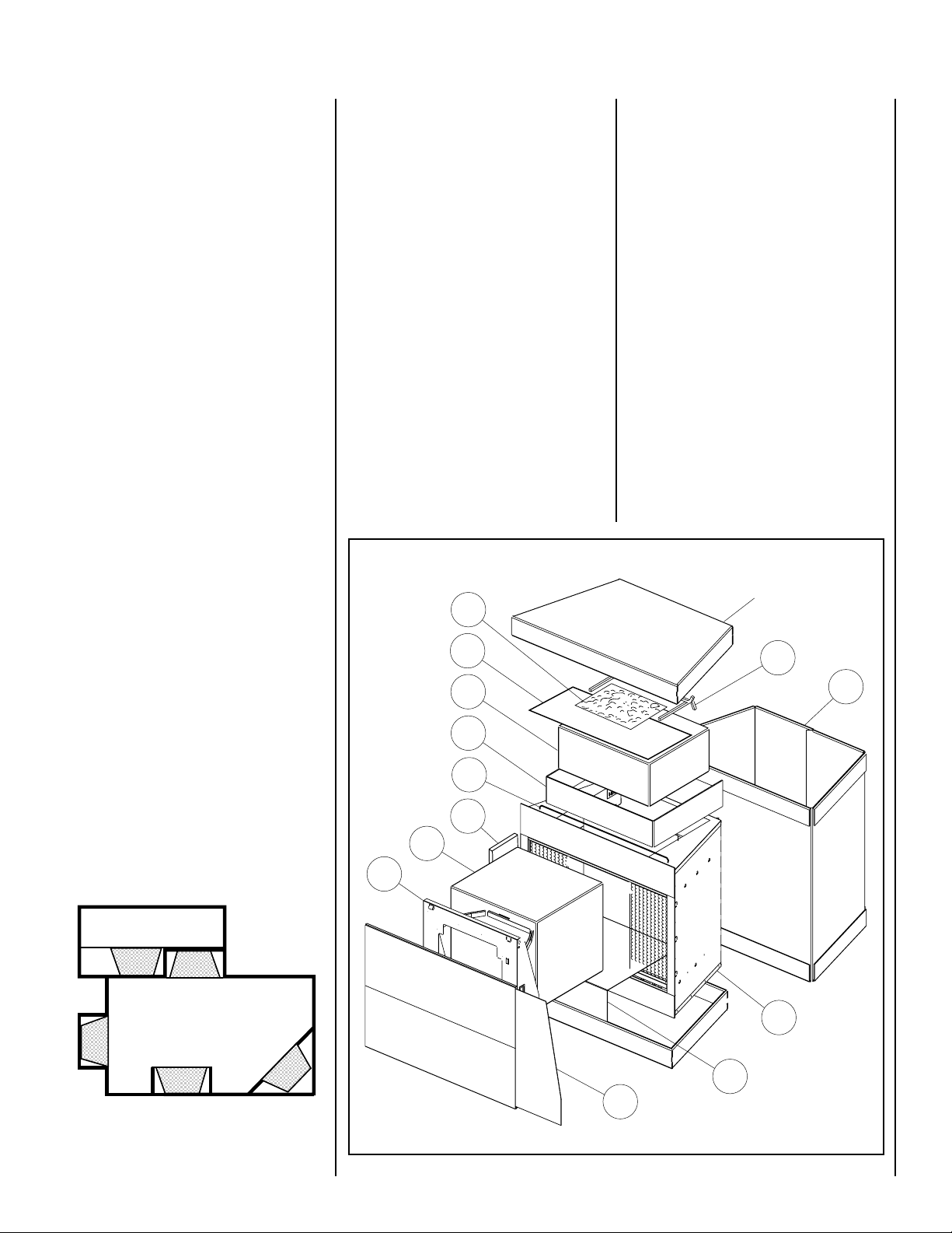
UNPACKING THE UNIT
Refer to
components as the product is unpacked.
Figure 2
for identification of the
5. Cut the bottom band and remove the carton wrapper (6). The wrapper can be used as
a working surface in front of the installation
opening.
14. To prevent a possible fire, do not block air
intakes or exhausts in any way. Do not use near
soft surfaces, like a pillow, where openings
may become blocked.
15. This appliance has hot and arcing or sparking parts inside. Do not use it in areas where
gasoline, paint or flammable liquids are used or
stored. This fireplace should not be used as a
drying rack for clothing, nor should Christmas
stockings or other decorations be hung near it.
16. Use this appliance only as described in this
manual. Any other use is not recommended by
the manufacturer and may cause a fire, electric
shock or injury to persons.
17. Avoid the use of an extension cord because the extension cord may overheat and
cause a risk of fire. However, if you have to
use an extension cord, the cord shall be No.
16 AWG minimum size and rated not less
than 2025 Watts. The extension cord must
be a three wire cord with grounding type plug
and cord connection.
18. SAVE THESE INSTRUCTIONS.
LOCATING YOUR REFLECTIONS
TM
ELECTRIC FIREPLACE
Be sure to identify all components before
proceeding with the installation.
1. Cut the top band of the package assembly
and lift the container top off. This top can be
used as a clean surface to assemble the television assembly.
2. Remove the grate (1) and ember bed (2) and
dust cover (11), set them aside in a safe place
off of the floor.
3. Discard the corrugated support (3) and lift
out the log package (4). Set it with the grate
and ember bed. Remove the door rail and
grille cover (12) and set it aside.
4. A panel of glass (5) is located in the front of
the carton wrapper. Lift the glass panel out
and set it with the logs. All of these items will
be installed in the final phase.
TYPICAL PACKAGING
2
11
4
6. Remove the Television support tray (7)
from the unit. Place it on the carton top for
assembly shortly.
7. Remove the television box (8) from inside
the unit and set it near the support tray. Remove the side refractory panels (13).
8. Remove and discard the protector pad (9).
9. Lift the unit (10) off of the carton bottom
and set it in front of the framed opening on the
carton wrapper. Discard the bottom cap.
All of the components numbered should be
identified before proceeding. Order information for any missing components can be found
in the replacement parts list on page 12.
Carton Top
1
6
Your new fireplace may be installed into existing framing. It may also be built into a wall,
see
Figure 3
available from your dealer (
When choosing a location for your new fireplace, ensure that the general instructions are
followed. Also, for the best effect, install the
fireplace out of direct sunlight and away from
overhead lighting.
, or set in a freestanding mantle
see Figure 12
).
Figure 1
3
12
13
8
7
Figure 2
NOTE: DIAGRAMS & ILLUSTRATIONS NOT TO SCALE.
10
9
5
3
Page 4
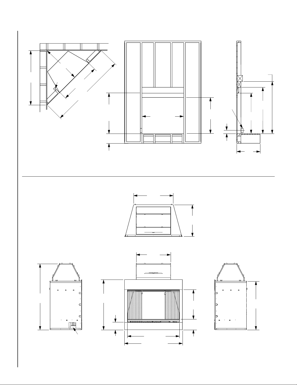
FRAMING SPECIFICATIONS
36 ¹⁄₄"
(921 mm)
51 ¹⁄₄"
(1302 mm)
Corner View
Figure 3
Electrical
Junction
Box
39 ¹⁄₄"
(997 mm)
72 ¹⁄₂"
(1841 mm)
38"
(965 mm)
(Header
Location)
9"
(229 mm)
(Recommended)
39 ¹⁄₄" (997 mm)
Front View
34"
(864 mm)
6 x 6
4 x 4
2 x 4
Electrical
Junction
Box
4"
(102 mm)
(1168 mm)
38"
(965 mm)
22"
(559 mm)
Side View
46"
41 ¹⁄₂"
(1054 mm)
FIREPLACE SPECIFICATIONS
45 ⁵⁄₈"
(1159 mm)
34 ³⁄₄"
(883 mm)
5 ³⁄₁₆"
(128 mm)
27 ¹⁄₂"
(699 mm)
Top View
23 ⁷⁄₈"
(606 mm)
22"
(559 mm)
20 ⁵⁄₈"
(524 mm)
7 ¹⁄₁₆"
(182 mm)
33 ⁵⁄₈"
(854 mm)
4
Figure 4
Left Side
Electrical Access
36" (914 mm)
40 ¹⁄₈" (1019 mm)
Front View
NOTE: DIAGRAMS & ILLUSTRATIONS NOT TO SCALE.
Right Side
Page 5
ASSEMBLY OUTLINE
Before You Start
Check your inventory list to be sure you have
all the necessary parts supplied in good usable condition. Check also for any concealed
damage.
UNIT PRE-ASSEMBLY
Before the installation can begin, two components need to be assembled.
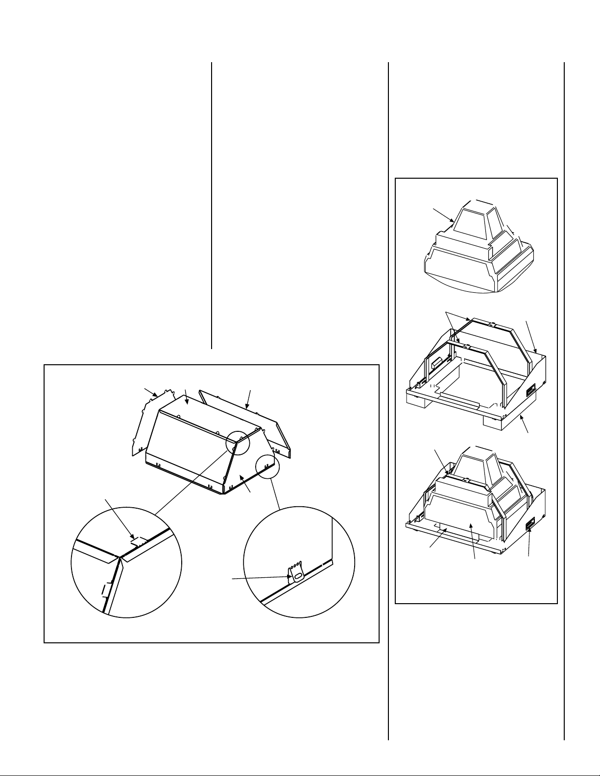
Dust Cover Assembly
The dust cover components come wrapped in
foam. There are five (5) parts to the assembly,
as shown in
Using the illustration for guidance, assemble
the components. Use the tabs to lock the
components together by bending each inward
as illustrated. Bend out the base tabs as
shown, to act as latches for installation later.
Set the assembly aside for installation later.
Figure 5
.
Television Assembly
Lay the television tray assembly onto a flat
surface. Use a cardboard protector to protect
the tray from marring.
Open the television box and remove all packing materials from the unit. Remove the television and place it beside the tray.
Note: The Television is provided with a remote
control. The fireplace does not require this
remote control. It may be discarded.
Untie the straps on the tray assembly and
loosen them completely. Drape the straps out
of the way as much as possible.
The television will lay face down on the tray as
shown in
centrally on the tray with the bottom against
the base support. The straps are then doubled
over the unit as shown in
very taut. Lift the assembly up onto its base
(as shown in
of the straps. Use the handles on each side of
the unit to lift and hold the unit.
Figure 6
Figure 9
. The television is oriented
Figure 6
) and verify the security
and drawn
Note: The TV screen protrudes below the
bottom frame of the tray assembly. Be sure to
support the tray assembly above the work
surface to protect the TV screen. Use the
spacers from the TV box to do this.
CAUTION: THE SECURITY OF THE STRAPS
IN THIS ASSEMBLY IS IMPORTANT SO THAT
THE INSTALLATION STEPS THAT FOLLOW
CAN BE PERFORMED SAFELY.
Television
(Face Down)
Television
Straps
Tray
Assembly
Locking
Tab Bent
Into Place
Figure 5
Side
Top
Base
Tabs
Front/Back
Side
Secure Television
Straps Tightly
Base
Support
Television
Base
Figure 6
Spacers
Handles
NOTE: DIAGRAMS & ILLUSTRATIONS NOT TO SCALE.
5
Page 6

UNIT INSTALLATION
1. Prepare the framed opening as illustrated in
Framing Specification
location is important. Verify the minimum
distance before starting the installation.
2. Locate the main electrical connection on the
left side of the fireplace and connect it to the
outlet installed during the framing. Verify that
the power to the receptacle is off.
3. Lift and slide the unit into the opening until
the face is flush up against the wall. Secure the
unit to the side framing members with 1"
drywall screws. See
4. Install the dust cover assembly into the top
of the fireplace from the underside until the
unit snaps into position. Fold out the tabs
around the base to support it in position. This
must be done before the television is installed.
5. Hook the television assembly onto the screen
rod pins and let the unit hang in position. Plug
the television power cord into the top receptacle routing behind the television latch (
Figure 9
6. The television assembly will rotate up into
the unit and lock onto the latch rod.
Figure 10
).
.
on page 4. The header
Figure 8
.
see
See
Ember
Compartment
Bulb And Socket
Figure 8
Power Cord
Secure
At These
Three (3)
Locations
From The
Inside
Screen Rod
CAUTION: THE TELEVISION ASSEMBLY IS
HEAVY. PLEASE CLEAR THE AREA IN FRONT
OF THE FIREPLACE BEFORE ATTEMPTING TO
SWING THE UNIT INTO POSITION. THE UNIT
MUST SWING SLIGHTLY PAST HORIZONTAL
TO LATCH. WE SUGGEST THAT TWO PEOPLE
PERFORM THIS STEP.
7. Two locking screws have been provided to
secure the television assembly after installation. Locate the two slots in the assembly
immediately in front of the latching rod. Hand
tighten the screws completely into the inserts
on both sides.
8. Refer to
track and install at this time. Two door clips
have been provided with these instructions.
Figure 7
for the location of the door
Door
Track
Tabs
Engagement Hooks
Figure 9
Latch
Rod
Detail Of
Top Receptacle
Top Receptacle
Hand Holds
Locking
Screw
Figure 7
6
Figure 10
NOTE: DIAGRAMS & ILLUSTRATIONS NOT TO SCALE.
Page 7

UNIT ACTIVATION
At this time all connections should be made
and tested to assure proper operation.
1. Locate the DVD disk for the DVD player in the
envelope with these instructions. Remove the
disk and set it aside. It will be installed shortly.
2. Locate the florescent bulb in the bottom of
ember compartment and install it into the
socket at that location (
3. Locate the Television RCA cord, suspended
from the fireplace top. Connect this cable to
the jacks located at the front of the television.
The red cable connector is for sound and
connects to the audio jack at the front of the TV
(
see Figure 11
white or yellow. This connector is for the video
and connects to the yellow jack in the front of
the television.
Attach the IR transmitter to the television at
the location shown in
correctly is very important.
The unit is ready to power-up for the first time.
4. Locate the circuit breaker for the fireplace at
the main electrical source and turn it on. Press
the power button on the remote. The ember
light will come on.
5. Press the DVD tray button on the DVD and
wait momentarily. The DVD drawer will open.
If the drawer does not open, power is not on.
6. Place the DVD disk into the tray and use the
button to close the DVD drawer.
The DVD is configured to play automatically
and the television is set to receive the DVD
signal directly. If the operation is correct, and
image of the flame should be on the Television
and sound should be coming from the unit.
). The other connector may be
refer to Figure 8
Figure 11
. Placing this
).
Center Grate On Ember Bed And Center Both Against
Figure 12
The Back Of Firebox
COMPLETING THE ASSEMBLY
After all functions are tested the assembly can
be completed.
Install the side refractory panels at this time. Be
sure to select the side that align best with the
back grout pattern.
1. Place the ember bed against the back wall of
the fireplace, over the ember compartment.
2. Place the grate onto the ember bed as
shown in
pattern as a guide to center the grate.
3. Assemble the logs onto the grate as identified in Installing The Logs on page 9
4. Pour elements of the loose embers over and
around the ember bed to your liking. Turn on
the unit to help judge the look of the ember
placement. It is best to pour all of the material
to cover the leading edge and spreading the
embers from there.
Figure 12
. Use the back brick
.
5. Check the placement one last time before
continuing.
Note: After glass placement, removing it for
adjustment is awkward and should be avoided.
6. Open the glass package and clean both
sides thoroughly. Cotton gloves have been
supplied to allow you to hold the glass without
smudging it. The underside of the glass is
inaccessible after installation. Any smudges
on the back side will be difficult to clean.
7. After the glass is clean, lift the glass with the
gloved hand and hold it in front of you like a
serving platter, with the narrow side away
from you. Insert the narrow end into the
fireplace and press the glass onto the two
black rubber tabs in the back of the firebox
(see
Figure 13
8. Lower the front edge down to the front lip
of the fireplace and hook the glass behind the
lip in the base cover.
If you haven't done so already, turn on the unit.
Step back and examine the flame placement in
correlation with the logs.
).
Figure 11
IR Transmitter Location
NOTE: DIAGRAMS & ILLUSTRATIONS NOT TO SCALE.
Refer to the Glass Frame Removal on page 9
and adjust if necessary.
A grill cover was packaged with the door rail.
This component inserts over the DVD player
tray opening with the Lennox logo on the right.
Two velcro dots have been provided in the
hardware kit to secure the grille if necessary.
7
Page 8

(Logs Not Shown
For Clarity)
Tabs
MANTELS
Combustible and Non-combustible mantels
may be installed at any height above the appliance opening.
CLEARANCE TO COMBUSTIBLES
Glass
Tabs
Up
(Back)
Figure 13
(Front)
FINAL FINISHING
FINISH TO YOUR TASTE
There are a wide variety of “finished looks” for
these fireplaces, from formal wall decor with
elaborate mantels to rustic wood paneling or
warm brick facings.
Materials like stone, tile, brick, etc., may overlap the black front facing. Do not extend these
materials beyond the black facing and into the
firebox area. Do not cover outlet or face
opening. Be sure not to interfere with the
installation and operation of glass doors or
block the lower grilles. Use caulking material
to seal the black metal facing to the surround
material on the finished wall.
Combustible materials may overlap the face of
the fireplace as long as they do not encroach
into the firebox opening (
Sidewall May
Be At Any
Distance From
The Face
Opening
Hearths And
Mantles May
Overlap The
Black Face.
DO NOT Block
The Lower Grille
Figure 14
see Figure 14
).
Front Lip
(Front)
HEARTH
A hearth is not mandatory, but it is recommended for aesthetic purposes. Hearth extension must not block the removable grille component (
see Figure 15
).
HEARTH EXTENSIONS
Do Not Cover Or Obstruct
5"
Maximum Thickness Of Hearth Extension
Above The Base Of The Appliance
Figure 15
Secure the hearth extension to the floor to
prevent possible shifting.
Cold climate installation recommendation:
When installing this fireplace against a noninsulated exterior wall or chase, it is mandatory that the outer walls be insulated to conform to applicable insulation codes.
Sides: 0 mm - 0 inches
Floor: 0 mm - 0 inches
Top: 0 mm - 0 inches
CABINET INSTALLATIONS
Cabinets are available from your dealer which
allow for fast, convenient installation of your
fireplace against existing walls.
ELECTRICAL CONNECTIONS
A 15AMP, 120 Volt, 60Hz circuit, with a properly grounded outlet, is required. Preferably,
the fireplace will be on a dedicated circuit, as
other appliances on the same circuit may cause
the circuit breaker to trip, or the fuse to blow,
when the heater is in operation.
The unit comes standard with a 5 ft. (1524mm)
long three wire cord, exiting the left side of the
fireplace. Plan the installation to avoid the use
of an extension cord. If an extension cord
must be used, it must be a minimum 16AWG,
three wire with grounding type plug, and connector and rated not less than 2025 Watts.
A new electrical outlet can be installed inside the
frame construction, if permitted by local codes.
The EV-220 kit is available from your dealer that
will allow this appliance to be connected to a
220V 15 Amp supply.
The kit contains a power cord connector and
heater element for a standard 220V single phase
connection.
Refer to the electrical diagram on page 11.
ELECTRICAL SPECIFICATIONS
Voltage: 120VAC,60Hz 240VAC,60Hz
Total Amps: 12.5 Amps 12.5 Amps
Total Watts: 1500 Watts 3000 Watts
Heater Rating: 1300 Watts 2500 Watts
WARNING: ELECTRICAL OUTLET WIRING MUST COMPLY WITH LOCAL
BUILDING CODES AND OTHER APPLICABLE REGULATIONS TO REDUCE THE
RISK OF FIRE, ELECTRICAL SHOCK AND
INJURY TO INDIVIDUALS.
8
NOTE: DIAGRAMS & ILLUSTRATIONS NOT TO SCALE.
Page 9

DO NOT USE THIS FIREPLACE IF ANY PART
OF IT HAS BEEN UNDERWATER. IMMEDIATELY CALL A QUALIFIED SERVICE TECHNICIAN TO INSPECT THE FIREPLACE AND REPLACE ANY PART OF THE ELECTRICAL SYSTEM WHICH HAS BEEN UNDER WATER.
A
HARD (DIRECT) WIRE CONNECTION
If desired, a qualified electrician may remove
the cord connection and wire this unit directly
to the household wiring.
Any electrical re-wiring of this appliance
must be done by a qualified electrician.
INSTALLING THE LOGS
1. Turn off power to the unit.
2. Place Log Assembly A on the grate first and
center it against the back of the grate, engaging the notch at the bottom right hand side of
the log assembly to the right grate bar. The
correct placement of Log Assembly A is important to provide the proper visual effect.
Placement of the other logs can be adjusted to
suit individual taste. Our suggested placement is shown in
Note: Log D is provided with a notch on its
bottom side to be engaged over the left grate
bar. Log E should be placed in the cradled
depression in the middle of the ember bed,
charred end to the left.
Figure 16.
SERVICE INSTRUCTIONS
This appliance has been designed to provide
many years of trouble free service. The components that will need to be serviced have been
kept to a minimum. Periodic dusting of the
glass and display is all that should be required.
CAUTION: DISCONNECT POWER BEFORE
ATTEMPTING ANY MAINTENANCE OR
CLEANING TO REDUCE THE RISK OF FIRE,
ELECTRICAL SHOCK OR PERSONAL INJURY.
GLASS FRAME REMOVAL
To access the logs, grate embers and lights,
the glass panel needs to be removed. An
illustration of the glass panel installation is
shown in
First sweep the screens inward and tie up and
out of the way. The glass is not secured by any
fasteners. The back rests on two insulated
tabs and the front is hooked behind a lip.
Figure 13
.
B
C
D
(Notch)
D
Figure 16
CAUTION: WHEN REMOVING THE GLASS,
DO NOT LET THE BACK OF THE PANEL SLIP
OFF OF THE INSULATED TABS IN THE BACK.
THIS COULD ALLOW THE GLASS TO DROP
INTO THE REFRACTORY PANELS OR LOGS
AND BREAK THEM.
The lower front corners of the glass are
exposed to provide a place to grip the glass
panel. Grip the corners firmly; lift the panel
back and up against the top of the unit.
Disengage the glass from behind the front
lip and rotate the front upwards. Slide one
hand under the glass and support the panel.
Draw the glass out of the unit and set it
carefully aside.
GLASS INFORMATION
1. This unit will not operate properly with
missing or broken glass.
2. Do not strike or slam the glass.
3. Do not use abrasive cleaners to clean the
glass.
4. This appliance uses tempered glass. Replacement of the glass as supplied by the
manufacturer should be done by a qualified
service technician.
(Notch)
E
B
E
A
MANUAL OPERATION
Switches have been placed on the unit to allow
operation without the remote.
Switches are in the upper right hand corner
of the face opening behind the screen (
Figure 17
The pad labeled P nearest the center will turn
the fireplace on and off. The pad to the right
of that, labeled H, will turn the heater on and
off.
Note: The heater will not operate without the
unit ON.
Figure 17
).
C
see
NOTE: DIAGRAMS & ILLUSTRATIONS NOT TO SCALE.
9
Page 10

REMOTE CONTROL OPERATION
PICTURE ADJUSTMENT
The Reflections Electric Fireplace is provided
with an Infrared Remote Control. All functions of the fireplace are provided through the
remote. The remote provided with the T.V.
should not be used.
The functions identified on the remote (see
Figure 18
A. All ON/All OFF
Press once; the embers light and the flame
come on after a brief warm up period. Pressed
again and all functions end immediately.
B. Embers ON/OFF
This button will turn the embers ON and OFF
independent of the main button.
C. Menu
To activate the menu for adjusting color and
brightness.
D. Heater ON/OFF
This button will turn the heater ON and OFF after
the unit is activated.
E. Volume
Increase:
Decrease:
F. Setting Control
Increase:
Decrease:
G. Flame Speed
Alternates between fast and slow flame speed.
) are as follows:
+
–
COLOR ADJUSTMENT
To adjust Color, Tint and Brightness, use the
Menu (button C) along with E and F as follows.
The menus displayed will be upside down and
backwards. This is a step that should only be
required once.
The television will come with all adjustments
at normal. If you wish to enhance the color,
adjustments can be made.
Step 1. Press the MENU button so that the
menu display appears on the TV screen.
Step 2. Press the VOL(ume) button so
that "PICTURE" is selected.
Step 3. Select the feature you wish to adjust
+
with the MENU or button and adjust
it with the VOL(ume) or button.
–
BRIGHT
Adjust until the whitest parts of the picture are
as bright as you prefer.
+
: Increase Brightness, : Decrease
Brightness
–
CONTRAST
Adjust to increase or decrease contrast.
+
: Increase Contrast, : Decrease
Contrast
–
COLOR
Adjust to be a brilliant or pale color.
: Be Brilliant Color, : Be Pale Color
+
–
TINT
Adjust to obtain natural flame tones.
+
: Greenish Tone, : Reddish Tone
–
TROUBLESHOOTING
Due to the nature of all electronic devices,
interference from other electrical sources
could set the units out of phase. The television and DVD player could operate with one
ON and the other OFF rather than both ON,
both OFF. If this occurs, the television can be
turned ON (or OFF) manually with the button
(
shown in Figure 18
back in sync from that point forward.
). This will put the units
A
D
B
E
C
F
G
Figure 18
REPLACING LIGHT BULB
This fireplace uses a 120 Volt, compact fluorescent light bulb (900 Lumens). The light is
located under the ember bed of the unit.
CAUTION: DO NOT EXCEED A 15 WATT BULB.
USE OF A HIGHER RATED BULB MAY RESULT
IN A FIRE, CAUSING PROPERTY DAMAGE,
PERSONAL INJURY OR LOSS OF LIFE.
CAUTION: DO NOT REPLACE THE COMPACT
FLUORESCENT LIGHT BULB WITH AN INCANDESCENT BULB.
1. Turn off power to the unit.
2. Let the fireplace cool, if it has been operating.
3. Remove the glass reflector panel. Remove
logs and ember bed.
4. Examine the bulb to determine if it needs to
be replaced.
10
5. While holding the socket, unscrew the de-
fective bulb.
6. Install the new light bulb by screwing it in
while holding the socket.
7. Reinstall the ember bed, log set and glass
panel.
NOTE: DIAGRAMS & ILLUSTRATIONS NOT TO SCALE.
Page 11

Figure 19
IR Transmitter Location
MAINTENANCE OF MOTORS
The motors used on the fan are pre-lubricated for extended bearing life and require no further lubrication. However, periodic cleaning/vacuuming of
the fan/heater is recommended.
CAUTION: MAKE SURE THAT THE POWER IS TURNED OFF BEFORE PROCEEDING.
WIRING DIAGRAM
Wiring diagrams are provided here for reference purposes only.
CAUTION: LABEL ALL WIRES PRIOR TO DISCONNECTION WHEN SERVICING CONTROLS. WIRING ERRORS CAN CAUSE IMPROPER AND
DANGEROUS APPLIANCE OPERATION.
Grounded Center Tap (White)
EV-220 Heater Kit
220V 15A Single Phase
120V 15A
Single Phase
Cord Set
-120Volt (Red)
Ground (Green)
+120 (Black)
(connections Labeled)
Cord Set
Controll Board
Heater Coil
Above Face Opening
Below Face Opening
FAN
+120 (Black)
Common (White)
Common (White)
+120 (Black)
HEATER
EMBER LAMP
+120 (Black)
Common (Black)
VIDEO
TELEVISION
AUDIO
DVD PLAYER
IR Transmitter (TV)
MANUAL
SWITCHES
P
IR
Receiver
IR Transmitter (DVD)
H
NOTE: DIAGRAMS & ILLUSTRATIONS NOT TO SCALE.
11
Page 12

TROUBLESHOOTING DIAGRAM
TROUBLESHOOTING:
Miscellaneous Errors: Before beginning any troubleshooting, check that the following items are setup correctly. The unit should be
plugged in and have power. The remote has the batteries installed properly. The ember bulb is installed. If these steps are correct,
the embers will turn on and off with the hand held remote.
Symptom:
• No Power to Television.
Problem/Test: Repair:
• Plug any 110V lamp or night light into
the fireplace receptacle and test.
• If the receptacle is good, check for out of
Sync. If the receptacle is bad, call for Service.
• Embers or Image turn off
unexpectedly.
• Television blue screen.
• Dancing Dolphins on TV.
• DVD pauses or skips.
• TV displays the word GAME.
• Flame image is green or
purple and connot be corrected.
• Heater shuts off by itslef or
won’t come on.
TROUBLESHOOTING:
• Problem: Out Of Sync.
• Symptom: Television is on with no image.
Ember bed is on with television off.
• Test the heater button on the remote.
Does the heater come on?
• Press the On/Off button once.
• Test the heater again.
• Programming error.
• DVD disk missing.
• DVD paused.
• DVD Disk error or heater motor
vibration.
• No Video Input.
• Magnetic Field Interference.
• Heater obstructions or failure.
NO
• Call For Service.
• Insert disk or Replace DVD disk.
• Cycle Off and 0n. Call for Service if it
occurs frequent.
• Clean DVD and Disk. Replace Disk. Check
blower for vibration (Call for Service).
• Connect or Switch the video inputs to the
TV. Try Out of Sync process.
• Call Service for Degaussing.
• Call Service for inspection.
YES
• Turn the heater off (not the power).
• Remove the lower trim cover.
• Open and close DVD tray.
• Locate the TV power button. Turn the TV on.
• Turn the Embers ON (if OFF).
• Cycle the Remote OFF and ON.
12
• Understanding the problem:
• The remote sends a unique coded signal to the fireplace. The fireplace receives the signal and retransmits a different code to
each element of the fireplace in a particular order. Television and DVD players use the same signal for ON as OFF. If one or the
other is off, the fireplace cannot distinguish. Keep a couple of rules in mind. The heater will not turn on when the fireplace is off,
the TV is easiest to turn off and on manually and opening and closing the DVD tray turns it on.
TROUBLESHOOTING:
• Understanding the problem:
• The remote sends a unique coded signal to the fireplace. The fireplace receives the signal and retransmits a different
code to the television. If the signal sent to the television “leaks” to the fireplace receiver - the fireplace gets confused.
Proper placement of the television IR transmitter is critical.
• Problem: Television IR Placement.
• Symptom: The unit turns on - Television
Volume and Menu adjustment troubles.
• Locate the IR Receiver on the fireplace (
and cup a hand around the module. Place the remote
in your hand and toggle the remote MENU button.
Does the Menu display ON and OFF properly?
NO
• Cover and completely mask the TV IR
transmitter module (
• Test the remote again.
refer to Figure 11
NOTE: DIAGRAMS & ILLUSTRATIONS NOT TO SCALE.
Figure 17
).
)
• Check the photo for placement of the IR
YES
Television transmitter (
• Remove and relocate the IR transmitter.
• Test the MENU button again.
Figures 11 & 19
).
Page 13

REPLACEMENT PARTS
1
9
8
4
3
5
12
6
11
10
2
7
13
LSE-36R
No. DESCRIPTION Part No. Qty.
Electric Fireplace Assembly – –
1. Refractory, (3 Piece Set) 42M46 1
2. Glass 42M50 1
3. Screen, (with Pulls) 66M45 2
4. Log Set (Boxed) H1091 1
5. Ember Bed 42M40 1
6. Grate LB-102458 1
7. Remote Control H1455 1
8. Floor LB-102434 1
9. Track, Door 499482 1
10. Door Support LB-102450 1
11. Door Clips LB-98109 2
12. Grille LB-102408 1
13. DVD Disk 42M35 1
Note: Lennox does not supply replacement bulbs. Use only 15 watt compact florescent bulbs. We recommend a bulb with 900 lumens.
NOTE: DIAGRAMS & ILLUSTRATIONS NOT TO SCALE.
13
Page 14

ACCESSORY PARTS AND COMPONENTS
FOR THE LSE-36R
The accessory parts and components shown
on this page are to be used only with your
LSE-36R electric fireplace. Separate installation instructions are packaged with all accessories.
If you encounter any problems or have questions concerning the installation or application of this system, please contact your distributor. For the name of your nearest distributor call:
LENNOX HEARTH PRODUCTS
1110 West Taft Avenue
Orange, CA 92865
Model Catalog Number Weight
LSE-36R H0807 177 lbs.
ACCESSORY COMPONENTS
The following items are available for use with
this appliance.
Upgrade 220V Heater Kit H0808 EV-220
Cabinet Surround Kit, Wall
- Paint Grade H1282 CSKW-PG
- Unfinished Oak H1283 CSKW-UO
- Finished Oak H1284 CSKW-FO
86L26 36 ABF
86L27 36 ABF-BB
Bi-Fold Doors 86L28 36 ABF-BS
Cabinet Surround Trim Kit
- Bottacino Beige H1285 CSTK-BB
- Jade Green H1286 CSTK-JG
- Misty Black H1287 CSTK-MB
Glass Enclosure Panels 27M31 36GEP-BS
27M30 36GEP
To ensure warranty and to prevent a potential
fire hazard, do not use any other doors on
these appliances.
14
NOTE: DIAGRAMS & ILLUSTRATIONS NOT TO SCALE.
Page 15

NOTE: THIS PAGE INTENTIONALLY LEFT BLANK.
NOTE: DIAGRAMS & ILLUSTRATIONS NOT TO SCALE.
15
Page 16

The manufacturer reserves the right to make changes at any time, without notice, in design,
materials, specifications, prices and also to discontinue colors, styles and products.
Consult your local distributor for fireplace code information.
Printed in U.S.A. © 2003 by Lennox Hearth Products
P/N 850,019M REV. B 04/2007
16
NOTE: DIAGRAMS & ILLUSTRATIONS NOT TO SCALE.
1110 West Taft Avenue
Orange, CA 92865
 Loading...