


INSTALLATION AND OPERATION MANUAL
Direct-Vent Gas Stove
The Epic™ Gas Stove is factory equipped for 40,000 BTU input and can be converted to 33,000 using the smaller orifice provided.
Retain These Instructions For Future Reference
P/N 775,223M Rev. B, 03/2008
A French manual is available upon request. Order P/N 775,223CF. Ce manuel d’installation est disponible en francais, simplement en faire la demande. Numéro de la pièce 775,223CF.
In the Commonwealth of Massachusetts:
•Installation must be performed by a licensed plumber or gas fitter
•See Table of Contents for location of additional Commonwealth of Massachusetts requirements
Report No. 050-S-21b-5 |
Epic™ 33/40 (EPIC33/40) |
US |
|
 WARNINGS
•Hot! Do not touch! The glass and surfaces of this appliance will be hot during operation and will retain heat for a while after shutting off the appliance. Severe burns may result.
•Carefully supervise children in the same room as appliance.
•These appliances may be installed in an aftermarket permanently located, manufactured (mobile) home (USA only), where not prohibited by local codes. This appliance is only for use with the type of gas indicated on the rating plate. This appliance is not convertible for use with other gases unless a certified kit is used.
•Lennox™ gas-burning appliances are designed for use as a supplemental heater. They are not intended for continuous use as a primary heat source.
WARNING: If the information in this manual is not followed exactly, a fire or explosion may result causing property damage, personal injury or loss of life.
Do not store or use gasoline or other flammable vapors or liquids in the vicinity of this or any other appliance.
WHAT TO DO IF YOU SMELL GAS:
•Do not light any appliance.
•Do not touch any electrical switch; do not Use any phone in your building.
•Immediately call your gas supplier from a neighbor’s phone. Follow your gas supplier's instructions.
•If your gas supplier cannot be reached, call the fire department.
Installationandservicemustbeperformedbyaqualified installer, service agency or the gas supplier.
AVERTISSEMENT:Assurez-vousdebiensuivrelesinstruc- tionsdonnées danscettenoticepourréduireauminimum le risque d’incendie ou d’explosion ou pour éviter tout dommage matériel, toute blessure ou la mort.
POUR VOTRE SÉCURITÉ: Ne pas entreposerni utiliser d'essence ni d'autres vapeurs ou liquides inflammables à proximité de cet appareil ou de tout autre appareil.
POUR VOTRE SÉCURITÉ: Que faire si vous sentez une odeur de gaz:
•Ne pas tenter d'allumer d'appareil.
•Ne touchez à aucun interrupteur.
•Ne pas vous servir des téléphones se trouvant dans le bâtiment
•Appelez immédiatement votre fournisseur de gaz depuis un voisin. Suivez les instructions du fournisseur.
•Si vous ne pouvez rejoindre le fournisseur de gaz, appelez le service des incendies.
L'installation et l'entretien doivent être assurés par un installateur ou un service d'entretien qualifié ou par le fournisseur de gaz.

 Cautions and Safety
FOR YOUR SAFETY do not install or operate your Epic™ gas stove without first reading and understanding this manual. Any installation or operation of the appliance deviating from that which is stated in this manual WILL void the warranty and may be hazardous.
INSTALLATION AND REPAIR SHOULD ONLY BE DONE BY A QUALIFIED SERVICE TECHNICIAN. DO NOT ATTEMPT TO SERVICE THE APPLIANCE YOURSELF.
The stove should be inspected and cleaned before use and at least annually by a qualified service technician. More frequent cleaning may be required due to excessive lint from bedding material, carpeting, etc.
It is imperative that control compartments, burners and circulating air passageways of the room heater be kept clean.
Adequate clearances around the combustion chamber and accessibility clearances for servicing and proper operation must be maintained.
Turn off the gas before servicing this appliance. It is recommended that a qualified service technician perform an appliance check-up at the beginning of each heating season.
All installations must conform with all local, state and national codes. In the absence of local codes, the installation must conform with National Fuel Gas Code ANSI Z223.1-latest edition, also known as NFPA 54 (In Canada, the current CAN/CSA B149.1 installation code). Refer to the National Fuel Gas Code and local zoning and code authorities for details on installation requirements. Your Epic gas stove must be vented to the outside in accordance with the latest edition of the National Fuel Gas Code.
This gas stove MUST be vented directly to the outside and MUST NEVER be attached to a chimney serving a separate solid fuel burning appliance. Each gas appliance MUST USE a separate vent system. Common vent systems are PROHIBITED.
Mobile home installations must conform with the Mobile Home Construction and Safety Standard, Title 24 CFR, Part 3280 (in Canada CAN/CSA Z240 MH), or, when such a standard is not applicable, the Standard for Mobile Home Installations, ANSI A225.1 - latest edition.
The appliance, when installed, must be electrically grounded in accordance with local codes or in the absence of local codes, with the National Electrical Code, ANSI/NFPA 70 - latest edition. In Canada, the current CSA C22-1 Canadian Electrical Code - latest edition.
Do not make any make-shift compromises during installation. Any modification or alteration may result in damage to the appliance or dwelling and will void the warranty, certification and listings of this unit.
Failure to use manufacturer provided parts, variations in techniques and construction materials or practices other than those described in this manual may create a fire hazard and void the limited warranty.
Your Lennox™ gas stove must be equipped for the proper fuel type and altitude at which it will be operated. Any operationoutsidetheparametersoutlinedinthismanual may result in a hazardous condition and will void the warranty. Please carefully read the sections pertaining to these subjects and/or be sure your appliance is properly equipped.
Do not use this stove if any part has been under water. Immediatelycallaqualifiedservicetechniciantoinspect the appliance and to replace any part of the control system and any gas control which has been under water.
Due to high temperatures, the stove should be located out of traffic areas and away from furniture and draperies.
Children and adults should be alerted to the hazards of high surface temperature and should stay away to avoid burns or clothing ignition. Young children should be carefully supervised when they are in the same room as the Lennox gas stove. Clothing or any other flammable material should not be placed on or near the stove.
Never use solid fuels such as wood, paper, cardboard, coal, or any flammable liquids, etc., in this appliance.
Any grill, panel, or glass removed for service MUST be replaced prior to operating the stove. Do not operate appliance with the glass front removed, cracked or broken. Replacement of the glass should be done by a qualified service technician.
DO NOT USE abrasive cleaner on the glass door assembly. DO NOT ATTEMPT to clean the glass door when it is hot.
Gold and nickel plated surfaces must be cleaned with glass cleaner and a clean soft cloth before firing the first time or fingerprints will remain permanently. NEVER use brass polish to clean gold or nickel, this will remove the plating!!!
When opening the lower door on the face while the stove is burning, pull at the far left or far right vent openings, because the door is hot during operation.
Lennox Hearth Products, its employees, or any of its representatives assume no responsibility for any damages caused by an inoperable, inadequate, or unsafe condition as a result of any improper operation, service or installation procedures, whether direct or indirect.
INSTALLER: THESE INSTRUCTIONS ARE TO REMAIN WITH THE HOME OWNER!

Table of Contents |
|
Cautions and Safety........................................................................................................ |
2 |
Orifice Size / Altitude Adjustment........................................................................................ |
4 |
Codes and Approvals....................................................................................................... |
4-5 |
New York City, New York (MEA)................................................................................. |
5 |
Commonwealth Of Massachusetts Requirements............................................................ |
5 |
Pre-Installation............................................................................................................. |
6-8 |
Features............................................................................................................. |
6 |
Packaging List...................................................................................................... |
6 |
Ratings.............................................................................................................. |
6 |
Preparing Your Epic Stove for Installation..................................................................... |
7 |
Dimensions......................................................................................................... |
7 |
Clearances to Combustibles..................................................................................... |
8 |
Installation.................................................................................................................. |
9-12 |
Trim Installation................................................................................................... |
9 |
Firebox Setup....................................................................................................... |
10 |
Brick Panel Installation........................................................................................... |
11 |
Log Set and Ember Installation.................................................................................. |
12 |
Vent Installation............................................................................................................ |
13-17 |
Venting.............................................................................................................. |
13 |
Residential and Mobile Home Installations................................................................... |
13 |
Vent Considerations............................................................................................... |
13 |
Vent Parts List...................................................................................................... |
14 |
Horizontal Vent Installation...................................................................................... |
14 |
Vertical Vent Installation......................................................................................... |
15 |
Flue Restrictors.................................................................................................... |
15 |
Horizontal Terminations.......................................................................................... |
16 |
Vertical Terminations............................................................................................. |
16 |
Horizontal Vent Termination Locations......................................................................... |
17 |
Gas Line Installation....................................................................................................... |
18 |
Gas Pressure Requirements..................................................................................... |
18 |
LP and Natural Gas Supplies..................................................................................... |
18 |
Operating Instructions..................................................................................................... |
19-22 |
Pre-Lighting Checklist............................................................................................ |
19 |
Lighting Instructions.............................................................................................. |
19 |
Flame Color and Behavior........................................................................................ |
20 |
Air Shutter Adjustment............................................................................................ |
21 |
Quiet Operation.................................................................................................... |
21 |
Paint Curing........................................................................................................ |
21 |
Optional Wall Thermostat........................................................................................ |
19 |
Operating Options................................................................................................. |
22 |
Millivolt Control System.......................................................................................... |
22 |
Maintenance and Servicing............................................................................................... |
23-26 |
Maintenance Checklist............................................................................................ |
23 |
Millivolt and Systems Checks.................................................................................... |
23 |
Vent Pipe Maintenance........................................................................................... |
24 |
Glass Door Cleaning and Maintenance......................................................................... |
24 |
Opening and Removing Door.................................................................................... |
25 |
Fuel Conversion.................................................................................................... |
26 |
Troubleshooting............................................................................................................. |
27 |
Parts List..................................................................................................................... |
28-29 |
Wire Harness Diagram.................................................................................................... |
30 |
Replacement Parts......................................................................................................... |
31 |
Accessories.................................................................................................................. |
32 |
Stove Labels................................................................................................................ |
33-34 |
Product Reference Information........................................................................................... |
36 |

Orifice Size/Altitude Adjustment
For altitudes above 2,000 feet (In Canada 4,500 FT/1370 M),the orifice should be de-rated by 4% for every 1,000 feet to maintain the proper ratio of gas to air. Improper orifice sizing may result in damage and unsafe conditions. Changing the orifice should only be done by a qualified service technician. Contact your Lennox Hearth Products dealer for proper orifice sizes. (see Page 26 for more information).
Smoke Detectors
Since there are always several potential sources of fire in any home, we recommend installing smoke detectors. If possible, install the smoke detector in a hallway adjacent to the room (to reduce the possibility of occasional false activation from the heat produced by the appliance). If your local code requires a smoke detector be installed within the same room, you must follow the requirements of your local code. Check with your local building department for requirements in your area.
Codes and Approvals
Certification
Gas appliances must be tested and certified by a nationally recognized testing and certification laboratory to ANSI (American National Standard Institute) gas appliance safety standards.
This stove has been tested and certified by OMNI -Test Laboratories to ANSI Z21.88 / CSA 2.33 Standard for Vented Gas Fireplace Heater and CGA 2.17-M91 and UL 307B Gas Burning Heating Appliances for Manufactured (Mobile) Homes in both USA and Canada.
It has met all necessary ANSI Standards and is fully certified for installation in any community. If there are any questions or if you need further substantiation either write to or call your Lennox Hearth Products dealer. If you have further questions, please contact Lennox Hearth Products.
Check all local building and safety codes before installation. The installation instructions and appropriate code requirements must be followed exactly and without compromise. In the absence of local codes the following standards and
codes must be followed.
The Epic™ Stove
•Must conform with all local, state and national installation codes. In the absence of local codes, the installation must conform with National Fuel Gas Code ANSI Z223.1 - latest edition, also known as NFPA 54 (In Canada, the current CAN/CSA B149.1 installation code). Refer to the National Fuel Gas Code and local zoning and code authorities for details on installation requirements.
•Mobile home installations must conform with the Mobile Home Construction and Safety Standard, Title 24 CFR, Part 3280 (in Canada CAN/CSA Z240 MH), or, when such a standard is not applicable, the Standard for Mobile Home Installations, ANSI A225.1 - latest edition.
•Must be vented directly to the outside in accordance with the latest edition of the National Fuel Gas Code and must never be attached to a chimney serving a separate solid fuel burning appliance.
•Has been certified for use with either natural gas or propane.
•Is not for use with solid fuels.
•Is approved for sitting rooms and/or bedrooms.

New York City, New York (MEA)
Installation of these fireplaces are approved for installation in New York City in the US state of New York (MEA#: 138-07-E).
Commonwealth Of Massachusetts Requirements
Note: The following requirements reference various Massachusetts and national codes not contained in this document.
For all side wall horizontally vented gas fueled equipment installed in every dwelling, building or structure used in whole or in part for residential purposes, including those owned or operated by the Commonwealth and where the side wall exhaust vent termination is less than seven (7) feet above finished grade in the area of the venting, including but not limited to decks and porches, the following requirements shall be satisfied:
Installation Of Carbon Monoxide Detectors
At the time of installation of the side wall horizontal vented gas fueled equipment, the installing plumber or gas-fitter shall observe that a hard wired carbon monoxide detector with an alarm and battery back-up is installed on the floor level where the gas equipment is to be installed. In addition, the installing plumber or gas-fitter shall observe that a battery operated or hard wired carbon monoxide detector with an alarm is installed on each additional level of the dwelling, building or structure served by the side wall horizontal vented gas fueled equipment. It shall be the responsibility of the property owner to secure the services of qualified licensed professionals for the installation of hard wired carbon monoxide detectors.
In the event that the side wall horizontally vented gas fueled equipment is installed in a crawl space or an attic, the hard wired carbon monoxide detector with alarm and battery back-up may be installed on the next adjacent floor level.
In the event that the requirements of this subdivision can not be met at the time of completion of installation, the owner shall have a period of thirty (30) days to comply with the above requirements; provided, however, that during said thirty (30) day period, a battery operated carbon monoxide detector with an alarm shall be installed.
Approved Carbon Monoxide Detectors
Each carbon monoxide detector as required in accordance with the above provisions shall comply with NFPA 720 and be ANSI/UL 2034 listed and IAS certified.
Signage
A metal or plastic identification plate shall be permanently mounted to the exterior of the building at a minimum height of eight (8) feet above grade directly in line with the exhaust vent terminal for the horizontally vented gas fueled heating appliance or equipment. The sign shall read, in print size no less than one-half (1/2) inch in size, “GAS VENT DIRECTLY
BELOW. KEEP CLEAR OF ALL OBSTRUCTIONS.”
Inspection
The state or local gas inspector of the side wall horizontally vented gas fueled equipment shall not approve the installation unless, upon inspection, the inspector observes carbon monoxide detectors and signage installed in accordance with the provisions of 248 CMR 5.08(2)(a)1 through 4.
Exemptions
The following equipment is exempt from 248 CMR 5.08(2)(a)1 through 4:
•The equipment listed in Chapter 10 entitled “Equipment Not Required To Be Vented” in the most current edition of ANSI Z233.1 / NFPA 54 (In Canada CAN/CSA B149.1 - current edition) as adopted by the Board; and
•Product Approved side wall horizontally vented gas fueled equipment installed in a room or structure separate from the dwelling, building or structure used in whole or in part for residential purposes.
MANUFACTURER REQUIREMENTS
Gas Equipment Venting System Provided
When the manufacturer of Product Approved side wall horizontally vented gas equipment provides a venting system design or venting system components with the equipment, the instructions provided by the manufacturer for installation of the equipment and the venting system shall include:
•Detailed instructions for the installation of the venting system design or the venting system components; and
•A complete parts list for the venting system design or venting system.
Gas Equipment Venting System NOT Provided
When the manufacturer of a Product Approved side wall horizontally vented gas fueled equipment does not provide the parts for venting the flue gases, but identifies “special venting systems”, the following require-
ments shall be satisfied by the manufacturer:
•The referenced “special venting system” instructions shall be included with the appliance or equipment installation instructions; and
•The “special venting systems” shall be Product Approved by the Board and the instructions for that system shall include a parts list and detailed installation instructions.
A copy of all installation instructions for all Product Approved side wall horizontally vented gas fueled equipment, all venting instructions, all parts lists for venting instructions and/or all venting design instructions shall remain with the appliance or equipment at the completion of the
installation.
•Installation and repair must be done by a plumber or gas fitter licensed in the Commonwealth of Massachusetts.
•The flexible gas line connector used shall not exceed 36 inches (92 centimeters) in length.
•The individual manual shut-off must be a T-handle type valve.

Pre-Installation
Features
Installation Options
Residential
Vented vertical and horizontal Manufactured (mobile) home Natural gas (NG) or propane (LP) Bedrooms
Optional wall-mounted or remote thermostat
Venting
This stove can be vented with Security™ Secure Vent™ pipe*. Coaxial pipe diameters are 6-5/8” outer and 4” inner. The combustion air for this stove is drawn from outside the house through the outer DV (direct vent) pipe. Room air is not required for combustion.
When planning your installation, select the correct length of vent pipe for your particular requirements. Determine the minimum clearance to combustibles from the rear of the unit to the wall. It is also important to note the thickness of the wall. Before cutting the vent hole through the wall make sure that ALL vent and termination clearances (see Page 17) will be met.
Electrical
The standard fan motor requires 120 Volts AC for operation. The stove is not dependent on the fan or an outside electrical supply to operate. WARNING - Electrical Grounding
Instructions - This appliance is equipped with a threeprong (grounding) plug for your protection against shock hazard and should be plugged directly into a properly grounded three-prong receptacle. Do not cut or remove the grounding prong from this plug.
* Other approved chimney brand is Simpson Dura-Vent DV-GS.
Millivolt Valve
This stove is operated with a millivolt valve and therefore burns even during a power outage.
Fuel
This stove comes from the factory equipped to burn natural gas at a specified elevation. The stove can be converted to burn LP gas (liquid propane) by changing the cassette (valve and pilot assembly) or installing a conversion kit. Only Lennox Hearth Products conversion kits can be used to convert from NG to LP or LP to NG. Contact your Lennox Hearth Products dealer for details.
Specifications
Pipe:Type - direct-vent Recommended manufacturer*
Security™ Secure Vent™*
Diameter - 6-5/8”x 4” for all installations
Stove Packaging List
The Epic™ gas stove comes with the following parts: 1 Stove Body with Burner Cassette
1 150 CFM Blower
1 3/8”x 9” Gas Pipe
1 3 pc. Brick Panel Set
1 4 pc. Log Set
1 Bag of Ember Material
1 Bag of Rock Wool
1 Bag of Flue Restrictors, Brick Panel Brackets and Tap-tites
1 Power Cord
1 Epic 33 Conversion Orifice
1 Installation and Operation Manual
Options
One required: Black Painted, Gold, Brushed Nickel, or Black Nickel Trim Kit
|
RATINGS |
Epic™ 33 (EPIC33) |
Epic™ 40 (EPIC40) |
|||||||||
|
|
|
|
|
|
|
|
|
|
|
|
|
|
NATURAL GAS |
LP GAS |
NATURAL GAS |
LP GAS |
||||||||
|
|
|||||||||||
|
|
|
|
|
|
|
|
|
|
|
|
|
Max/Min Input BTUh 0-2,000 Feet |
33,000 / 23,000 |
31,000 / 24,000 |
40,000 / 27,000 |
39,000 / 30,000 |
|
|||||||
(0-610 M)u |
|
|
|
|
|
|
|
|
|
|
|
|
Manifold Pressure (IN. WC) |
3.5 / 1.7 |
10.0 / 5.4 |
3.5 / 1.7 |
|
10.0 / 5.4 |
|
||||||
|
|
|
|
|
|
|
|
|
|
|
|
|
Min. Inlet Pressure (IN. WC) |
5.0 |
11.0 |
5.0 |
|
11.0 |
|
|
|||||
|
|
|
|
|
|
|
|
|
|
|
|
|
P4 Efficiency |
w |
56.98% |
63.58% |
63.54% |
|
65.10% |
|
|||||
|
|
|
|
|
|
|
|
|
|
|
|
|
Orifice (DMS) 0-2,000 Feet (0-610 M)u |
#36/.106 IN. |
#52/.064 IN. |
#31/.120 IN. |
#49/.073 IN. |
||||||||
|
|
|
|
|
|
|
|
|
|
|
|
|
uUnit factory equipped for 0-2000 FT/0-610 M, In Canada 0-4500 FT/0-1370 M |
|
|
|
|
|
|
|
|
|
|||
|
|
|
|
|
|
|
|
|
||||
vThe Steady State Efficiency numbers based on maximum vent configuration. |
|
|
|
|
|
|
|
|
|
|||
|
|
|
|
|
|
|
|
|
||||
wTested to CSA P.4.1-02 “Testing Method for Measuring Annual Fireplace Efficiency. |
|
|
|
|
|
|
|
|
||||
|
|
|
|
|
|
|
|
|||||
|
|
|
|
|
|
|
|
|||||
Electrical Rating: 120 VAC, 60 HZ, Less Than 2 Amps |
|
|
|
|
|
|
|
|
|
|
||
|
|
|
|
|
|
|
|
|
|
|
|
|
Preparing Your Epic™ Stove For Installation
Read all instructions before beginning your installation. If instructions have not been read carefully, your installation could void your warranty and may create a serious fire, health, or other safety hazard.
The Lennox Hearth Products warranty will be voided if one of the following occurs:
•Installation of any damaged stove or vent system component.
•Unauthorized modification of the direct vent system.
•Installation other than as instructed by Lennox Hearth Products, Security™ Chimneys, or Simpson DuraVent.
•Installation of any stove or vent system component not manufactured or approved by Lennox Hearth Products, Security™ Chimneys, or Simpson Dura-Vent.
When planning the installation for your Epic gas stove, it’s necessary to consider the following:
•Where the unit is to be installed
•The vent system configuration to be used
•Gas supply (NG or LP)
•Electrical wiring
•Optional accessories (door trim assembly and wallmounted or remote thermostat)
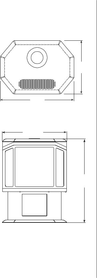
Dimensions
The gas line attaches to the gas valve at the lower left corner at the back of the stove. Test all gas connections for leaks with a gas leak test solution.
Top View
17”
(432mm)
23-1/2” (597mm)
Figure 1
Front View
23-1/2”
(597mm)
31-1/4” (794mm)
Figure 2
NOTE: DIAGRAMS & ILLUSTRATIONS ARE NOT TO SCALE.
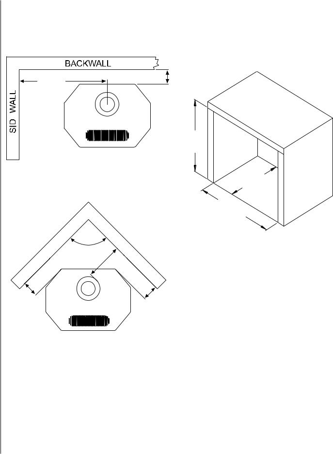
Clearances to Combustibles
Minimum clearances to combustible materials in inches (millimeters):
Parallel Installation
24-1/2” |
4” (102mm) |
(622mm) |
|
Min. |
|
12-1/2” 

 (318mm)
Min.
Alcove dimensions
The minimum width between the alcove side walls is 48” (1219mm). The minimum height of the alcove is 69” (753mm) and the maximum depth is 48” (1219mm).
Alcove Dimensions
69”
(753mm)
Min.
Figure 3
|
48” |
Corner Installation |
(1219mm) |
Max. |
48”
(1219mm)
Min.
90°
10-1/2” (267mm)
Min.
4-1/2” |
4-1/2” |
(114mm) |
(114mm) |
Min. |
Min. |
Figure 4
Floor Protection
A noncombustible hearth pad is not required. This stove may be installed on a combustible surface. Also, the floor beneath the stove must be stable, level, hard and strong enough to support the stove without a tipping hazard.
Figure 5
Pipe Clearances
All installations using a vertical termination cap must maintain one inch clearance between the direct vent pipe and combustibles. For horizontal runs of pipe, one inch of clearance to combustibles on the sides and bottom and two inches on the top of the pipe is required. See Page 16 for allowable pipe configurations.
NOTE: DIAGRAMS & ILLUSTRATIONS ARE NOT TO SCALE.
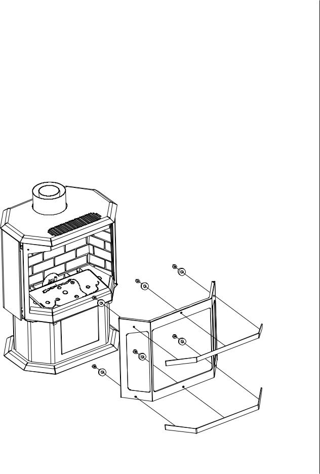
Installation
Trim Installation:
CAUTION: Always ensure that plated surfaces are clean and free of fingerprints before lighting stove. Fingerprints will leave permanent blemishes if left on plated surface when lit. When installation is complete, the trim should be gently cleaned with a soft cloth and either alcohol or glass cleaner. Do not overtighten nuts, overtightening can create visible dimples on the plated surface.
Packaging List: Trim pieces (2) - gold, brushed nickel, black nickel, or black, #6 nuts (6), #6 washers (6)
Tools Required: 5/16” nut driver or socket wrench
1.Remove the trim pieces and hardware from its packaging and ensure that all pieces are present before beginning installation. Take care not to scratch finished surfaces.
2.Open right side door by removing socket head cap screw located on the bottom of the side door near the front.
3.Open front door. Put trim in place by inserting trim studs into the corresponding holes in the door. The top piece of trim will only fit in one direction, but the bottom piece can be installed incorrectly. When placing the bottom piece of trim, make sure there is a small gap between the bottom of the trim piece and the bottom of the door. If the trim extends below the bottom of the door, the trim is on upside down.
4.Place one washer on each stud. Using a 5/16” nut driver, snug up the nuts on each piece of trim. Do not finish tightening nuts.
5.There should be approximately a 1/8” gap between the edge of the trim and the top and bottom edges of the door. Visually inspect the alignment of the trim and adjust if necessary.
6.Finish tightening nuts. CAUTION - DO NOT OVERTIGHTEN
NUTS!!!
Figure 6
NOTE: DIAGRAMS & ILLUSTRATIONS ARE NOT TO SCALE.

Firebox Setup
Burner Pan Diagram
Log Stands
1
2
3
Gas Ports
Air Deflector
4
Secondary Air Holes
Figure 7
Completed Firebox Setup
|
|
Figure 8 |
|
|
|
To ensure a proper burn leave a 1” space free of any |
Do not cover any secondary air holes or gas ports (see |
||
|
embers or rockwool directly in front of the air deflector |
Burner Pan Diagram above) behind this line. |
||
10 |
(see Burner Pan Diagram above). |
|
||
|
|
NOTE: DIAGRAMS & ILLUSTRATIONS ARE NOT TO SCALE. |
||
Brick Panel Installation
CAUTION: The brick panels are required for your appliance to function correctly and safely.
Packaging List: Rear brick panel (A), left brick panel (B), right brick panel (C), retaining brackets (D) - in flue restrictor bag
1.Remove the brick panels from the box and carefully unwrap them. The panels are fragile, so handle them with care. Remove the bag containing the brick retaining brackets
(D) and flue restrictors from the firebox.
D
4.Usingtheincludedscrews,installthebrickretainingbrackets
(D) above the left and right brick panels (B and C).
Figure 12
B A C
Figure 9
2.Install the rear brick panel (A) bottom first and stand it flush against the rear of the firebox ensuring the pilot cutout is at the bottom directly above the pilot.
Figure 10
3.Install the left panel (B) bottom first and stand flush against left wall of firebox. Repeat for right panel (C) against the right wall of firebox.
Figure 13
Figure 14
|
|
Figure 15 |
|
|
|
Figure 11 |
11 |
||||
NOTE: DIAGRAMS & ILLUSTRATIONS ARE NOT TO SCALE. |
|||||
|
|||||
|
|||||
 Loading...